

Carrier 50EN 480, 50EN 420, 50EH 415, 50EH 420, 50EH 480 Installation, Operation And Maintenance Instructions
...Page 1
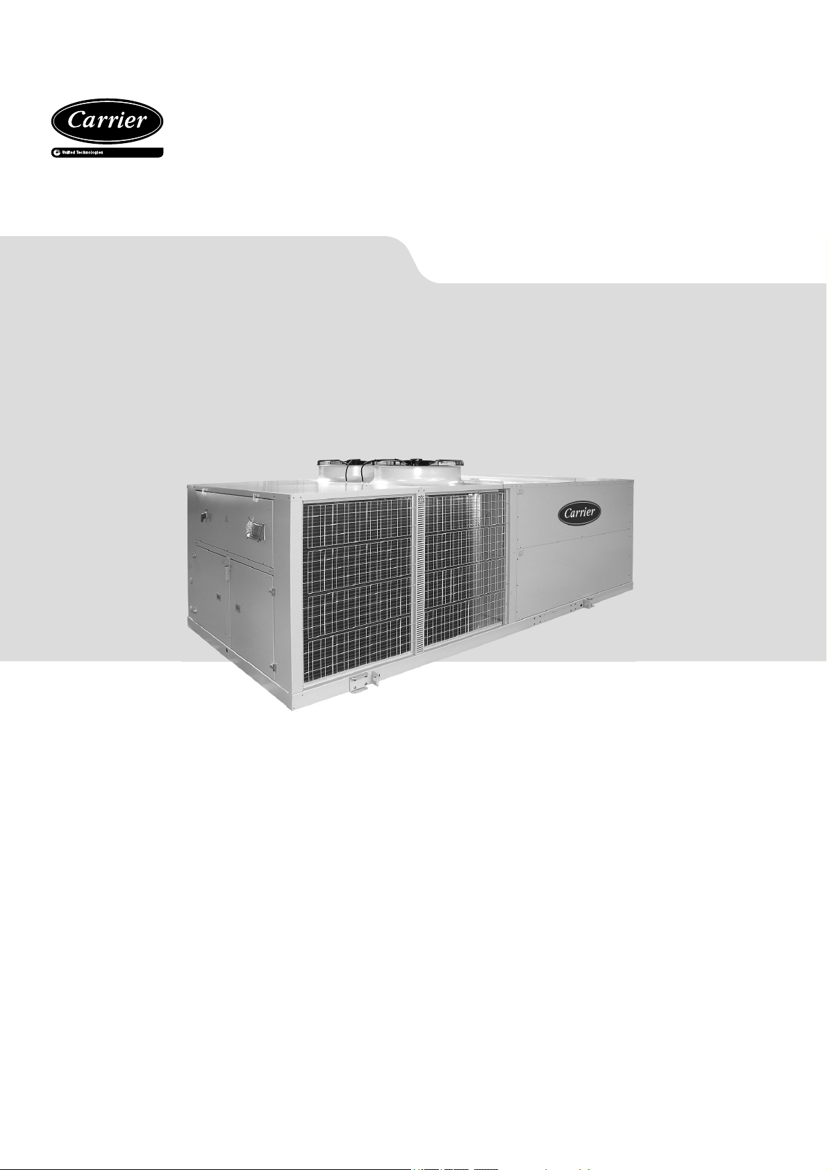
INSTALLATION, OPERATION AND
MAINTENANCE INSTRUCTIONS
Packaged rooftop units
and separated gas module option
50EN/EH 415-1200
Nominal cooling capacity 92.8 - 287.0 kW
Nominal heating capacity 99.3 - 290.7 kW
Translation of the original document 80049, 12.2018
Page 2

CONTENTS
1 - INTRODUCTION .................................................................................................................................................. 3
2 - UNIT IDENTIFICATION ....................................................................................................................................... 3
3 - POSSIBLE TYPES OF ASSEMBLIES ................................................................................................................. 4
4 - SAFETY ADVISE ................................................................................................................................................. 5
5 - OPERATION LIMITS............................................................................................................................................ 5
6 - TRANSPORT AND HANDLING ........................................................................................................................... 6
6.1 Centres of gravity ......................................................................................................................................... 7
6.2 Weight overview (kg) .................................................................................................................................... 8
7 - POSITIONING AND INSTALLATION .................................................................................................................. 9
7.1 Choice of location ......................................................................................................................................... 9
7.2 Anchorage for antivibrators ........................................................................................................................ 10
7.3 Recommended service clearance .............................................................................................................. 12
8 - ELECTRICAL CONNECTION ............................................................................................................................ 13
8.1 Installation norms ....................................................................................................................................... 13
8.2 Power supply .............................................................................................................................................. 13
8.3 Wire sizing .................................................................................................................................................. 13
8.4. CARRIERrtc electronic control .................................................................................................................. 13
8.5 Electric panel .............................................................................................................................................. 14
8.6 Location of sensors (2 circuits) ................................................................................................................... 15
9 - FANS AND AIR DUCTS ..................................................................................................................................... 17
9.1 Checks in the axial fans .............................................................................................................................. 17
9.2 Checks in the EC plug-fans ......................................................................................................................... 17
9.3. Checks in the centrifugal fans (optional) .................................................................................................... 17
9.4 Air ducts connections ................................................................................................................................. 18
10 - CONDENSATE DRAIN ....................................................................................................................................19
11 - SAFETY ELEMENTS ....................................................................................................................................... 20
12 - FACTORY OPTIONS AND ACCESSORIES .................................................................................................... 22
12.1 Filters ....................................................................................................................................................... 22
12.2 Hot water coil ........................................................................................................................................... 22
12.3 Electrical heaters ...................................................................................................................................... 23
12.4 Dampers hoods ........................................................................................................................................ 24
12.5 Stop-drop ................................................................................................................................................. 24
12.6 Rotary heat exchanger ............................................................................................................................. 25
12.7 Gas burner. ............................................................................................................................................... 26
12.8 Pre-assembly roofcurb ............................................................................................................................. 26
13 - COMMISSIONING ........................................................................................................................................... 27
13.1 Checks prior to commissioning ................................................................................................................ 27
13.2 Possible problems at commissioning ....................................................................................................... 28
13.3 Operational checks .................................................................................................................................. 28
14 - MAINTENANCE ............................................................................................................................................... 29
14.1 General recommendations ....................................................................................................................... 29
14.2 Servicing .................................................................................................................................................. 30
14.3 access to the main components ............................................................................................................... 30
15 - CONTROL AND ANALYSIS OF BREAKDOWNS ........................................................................................... 33
16 - FINAL SHUTDOWN ........................................................................................................................................ 34
16.1 Shutting down .......................................................................................................................................... 34
16.2 Recommendations for disassembly ......................................................................................................... 34
16.3 Fluids to be recovered for treatment ......................................................................................................... 34
16.4 Materials to be recovered for recycling ..................................................................................................... 34
16.5 Waste electrical and electronic equipment (WEEE) ................................................................................. 34
2
Page 3
1 - INTRODUCTION
The 50EN/EH range consist of autonomous and compact air-air
units of horizontal design, rooftop type.
They include inside all the components required for providing
the proper air conditioning to the installation.
● 50EN series: Units for cooling operation.
● 50EH series: Units for reversible heat pump operation.
The range of capacities of these units allows the air conditioning
of medium and large surface areas used for business or industry.
The unit is connected directly to an air distribution ductwork
without additional elements or equipment, pipes, cables, etc.
taking no fl oor space at all. This design reduces the cost of
installation, facilitates a quick connection and ensures reliable
operation.
After manufacturing, all units are charged with refrigerant
and are tested at the factory, verifying the correct operation
of all their components within the operating range for which
they are intended.
The units comply with European Directives:
● Machinery Directive 2006/42/EC (MD)
● Electromagnetic Compatibility Directive 2014/30/EU (EMC)
● Low Voltage Directive 2014/35/EU (LVD)
● Pressure Equipment Directive 2014/68/EU (Category 2) (PED)
● RoHS Directive 2011/65/EU (RoHS)
● Eco-design Directive 2009/125/EC (ECO-DESIGN)
● Energy Labelling Directive 2017/1369/EU (ECO-LABELLING)
● Harmonised Standard: EN 378-2:2012 (Refrigerating systems
and heat pumps - Safety and environmental requirements).
Technicians who install, commission, operate and service the
unit must possess the necessary training and certifi cations,
understand the instructions given in this manual and be familiar
with the specifi c technical characteristics of the installation site.
2 - UNIT IDENTIFICATION
Check the unit for any damage or missing components upon
delivery.
Check that the details on the label, the packing and the name
plate match the order.
If equipment has been damaged, or there is a shortfall in delivery,
notify accordingly.
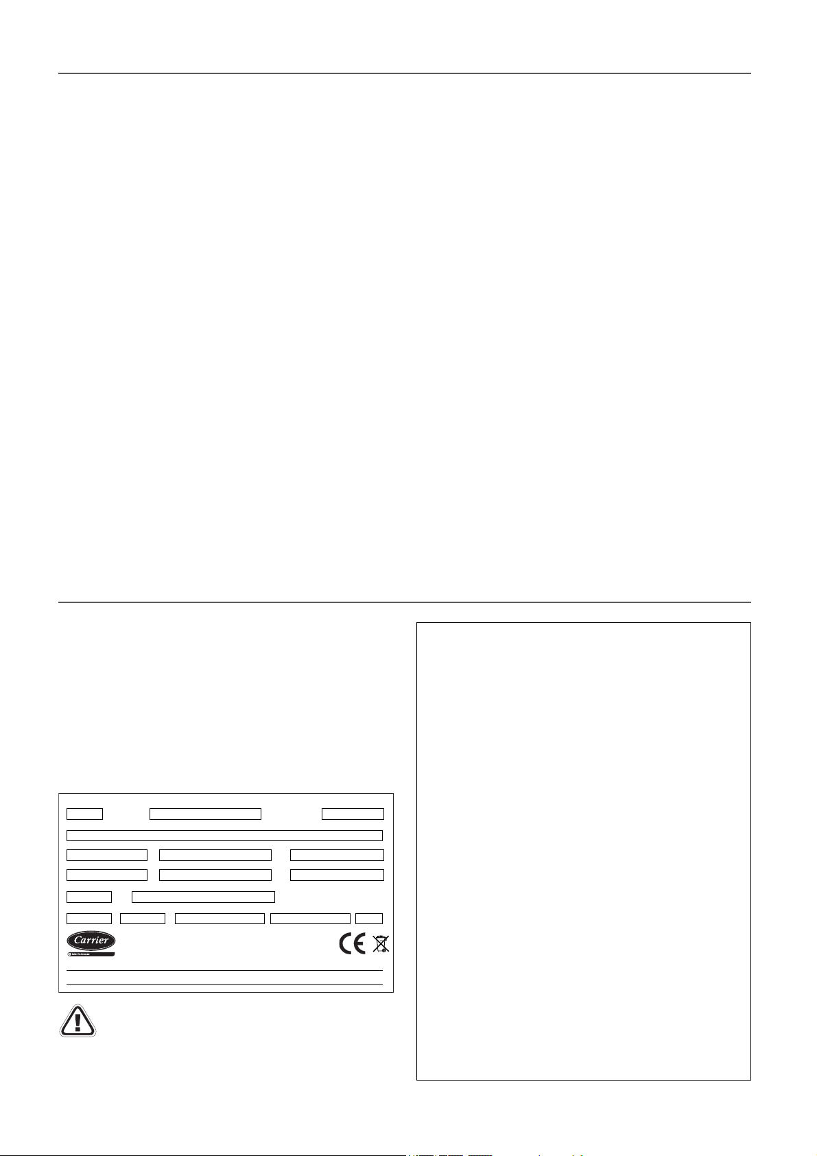
All units bear, legibly and indelibly, a name plate located in a
prime space, as appears in the attached image: Check that this
plate matches the correct model.
1
Producto\Product\Produit
Ref. Produit\Item Nbr
56 7
89 10
11 12
13 14 15 17
Contient des gaz à effet de serre fluorés \ Contains fluorinated greenhouse gases regulated by the Kyoto protocol
Contiene gases fluorados de efecto invernadero regulados por el protocolo de Kyoto
Important: The serial number must be used in all
correspondence regarding the unit.
Markings (name plate, punch marks, labels) must remain visible.
They must not be altered, removed or modifi ed.
Ref\Reference No Serie\serial Nbr.Año\An.Year
Refrig.KG (Fábrica\Factory\Usine)/Co2 Teq.Refrigerant
CARRIER SCS
Route de Thil
01122 Montluel-FRANCE
23
4
Max.Intensidad\Intensité\CurrentKit Elec.Tension\Voltage
16
Fabricante\Fabricant\Manufacturer:
Compañía Industrial de Aplicaciones Térmicas, S.A.
P. Ind. Llanos de Jarata s/n. 14550 Montilla-SPAIN
NoBoPeso\Poids\WeightPSmax(AP\HP) Temp. Max./ IPPSmax(BP\LP)
Legend
1
Year of manufacture
2
Commercial product name
3
Serial number
4
Description of the product
5
Purchase order number
6
Sales order number
7
Work order number
8
Power supply
9
Power output of the auxiliary electrical heaters kit (optional)
(kW)
10
Maximum absorbed current under full load (A) ( including
the electrical kit)
11
Type of refrigerant
12
Refrigerant content (kg) and Environment impact (CO
13
Maximum service pressure in the high pressure side
(R-410A = 42 bar)
14
Maximum service pressure in the low pressure side
(R-410A = 24 bar)
15
Maximum operating temperature (refer to “Opration limits”)
Maximum shipment and storage temperature: +50ºC
Electrical protection rating: IP54
16
Operation weight (kg) (empty weight + fl uid + refrigerant)
17
Notifi ed Body number for surveillance of the Pressure
Equipment Directive
Teq.)
2
3
Page 4
3 - POSSIBLE TYPES OF ASSEMBLIES
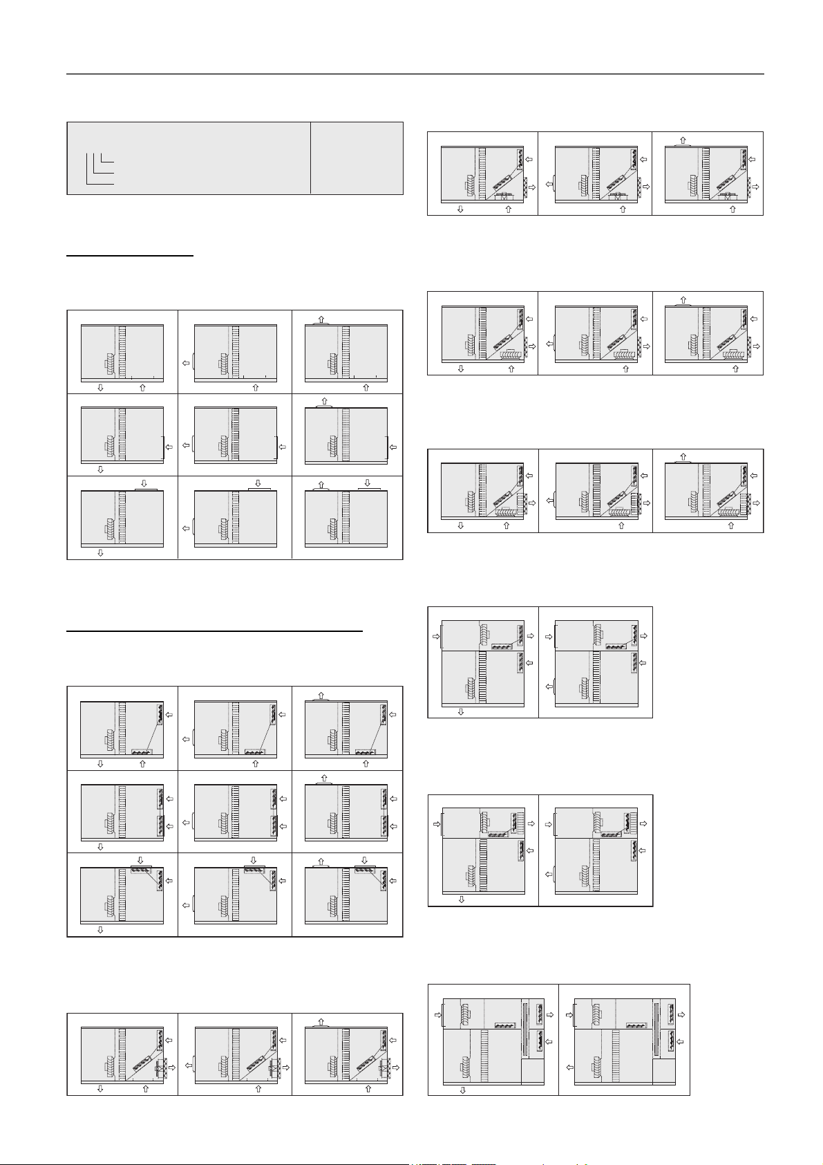
Depending on the indoor airfl ow direction
Mwxy
Assembly
Air supply (0 : standard, 1 : optional, 2 : optional)
Air return (0 : standard, 1 : optional, 2 : optional)
Type of assembly
Legend
I = Air supply
R = Air return
N = Fresh air inlet
E = Air extraction
Standard assembly
M0 assemblies: Change of supply and/or return air position
in the indoor circuit.
I
M002
R
M012
I
R
I
M022
R
R
I
I
M000
M010
M020
M001
I
R
R
M011
I
R
M021
R
R
MA assemblies: Axial return and air extraction fan (mixing
box of 3 dampers).
MA00
N
E
I
R
MC0 assemblies: Electronic lower EC plug-fan (mixing box
MA01
N
I
E
R
MA02
I
N
E
R
of 3 dampers).
MC00
N
E
I
R
MRC0 assemblies: Lower EC plug-fan (mixing box of 3
MC01
I
R
I
N
MC02
E
N
E
R
dampers) + cooling recovery circuit
MRC00
N
E
MRC01
N
I
E
I
MRC02
N
E
I
I
Assemblies with mixing box and free-cooling
MS assemblies: Fresh air intake with damper, interlocked
with return damper (mixing box of 2 dampers).
I
MS02
N
R
MS12
I
N
R
I
MS22
N
R
I
MS00
MS10
MS20
MS01
N
I
RI
R
MS11
N
I
R
R
N
MS21
R
I
I
R
R
MC1 assemblies: EC plug-fan or centrifugal fan in top box
(mixing box of 3 dampers).
MC10
R
N
I
E
R
N
MRC1 assemblies: EC plug-fan or centrifugal fan in top box
MC11
E
N
I
(mixing box of 3 dampers) + cooling recovery circuit.
N
R
N
MRC10
R
I
E
N
MRC11
R
I
E
N
R
I
ME assemblies: Axial air extraction fan (mixing box of 3
dampers).
ME00
N
ME01
I
E
RI
R
I
N
E
ME02
R
4
MWC1 assemblies (models 415 to 960): EC plug-fan in top
box (mixing box of 3 dampers) + rotary heat exchanger.
MWC10
R
N
E
I
E
R
N
MWC11
E
I
N
Page 5
4 - SAFETY ADVISE
To avoid any risk of accident during installation, commissioning
or maintenance, it is obligatory to take into consideration the
following specifi cations for the units: refrigerated circuits under
pressure, refrigerant presence, electrical voltage presence and
implantation place.
Because of all of this, only qualifi ed and experienced personnel
can perform maintenance tasks or unit repairs.
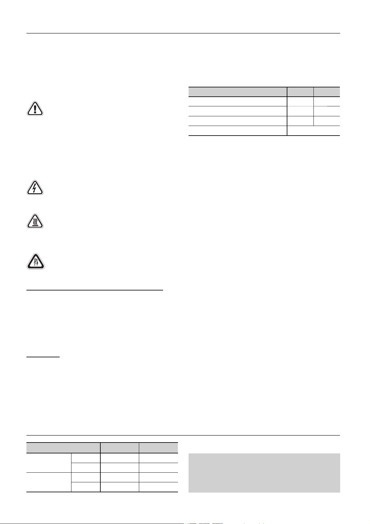
It is required to follow the recommendations and
instructions in this brochure, the labels, and the specifi c
instructions.
Compliance with the norms and regulations in eff ect is
mandatory. It is recommended to consult the competent
authorities regarding the applicable regulations for
users of units or components under pressure. The
characteristics of these units or components are
included on the plates of characteristics or in the
regulatory documentation provided with the product.
Caution: Before intervening in the unit, verify that the
main power to the unit is cut off . An electric shock can
cause personal damage. The main disconnect switch
is located in the unit’s electrical panel.
The compressor and line surfaces can reach
temperatures above 100ºC causing burns to the body.
In the same fashion, under certain conditions these
surfaces can reach very cold temperatures that can
cause freezing risks.
During any handling, maintenance or service operations,
the technicians involved must be equipped with safety
V-220005
gloves, glasses, shoes, insulating clothing, etc
Natural or propane gas leaks (optional burner)
● Do not operate electric switches or other objects which could
cause sparks.
● Improve the ventilation if located in a closed area.
● Close the gas supply valve.
● Ensure that there is no one in the vicinity of the leak and
request the intervention of installation staff .
Refrigerant
Important: These units contain R-410A, a fluorinated
greenhouse gas covered by the Kyoto protocol.
All interventions on the refrigerating circuit must be performed
in accordance with applicable legislation.
Within the European Union, it is necessary to observe regulation
(EU) No.517/2014, known as F-Gas, over Certain greenhouse
eff ect fl uoride gases.
Components of the R-410A R-32 R-125
Chemical formula
Weight ratio
Unitary global warming potential (GWP)
Global warming potential (GWP)
CH2F2 CHF2CF3
50% 50%
675 3.500
2.088
Ensure that refrigerant is never released to the atmosphere
when the equipment is installed, maintained or sent for disposal.
It is prohibited to deliberately release refrigerant into the
atmosphere. The operator must ensure that any refrigerant
recovered is recycled, regenerated or destroyed.
The operator is bound by the obligation to perform periodical
sealing tests on the refrigerating circuit according to the
regulation (EU) No.517/2014. Please, consult the frequency of
tests in chapter of “Maintenance”.
In case of a leak:
● Toxicity: According to EN 378-1, R-410A belongs to the A1/
A1 group, i.e. with high safety both in the mix and also in the
case of a leak.
● Although it is not toxic, in case of a leak to atmospheric
pressure the liquid phase evaporates. The resulting vapours
are still hazardous because they are heavier than air and
can force the latter out of the machine rooms. If refrigerant is
accidentally released, ventilate the room with fans.
● Although it is not fl ammable, keep them away from open
fl ames (e.g. cigarettes) as temperatures of over 300°C cause
their vapours to break down and form phosgene, hydrogen
fl uoride, hydrogen chloride and other toxic compounds. These
compounds may produce severe physiological consequences
if accidentally inhaled or swallowed.
● To detect leaks, an electronic leak detector, an ultraviolet lamp
or soapy water must be used . Flame detectors do not help.
● Immediately repair any refrigerant leak, using a recovery
unit specifi c for R-410A that avoids a possible mixture of
refrigerants and/or oils.
5 - OPERATION LIMITS
Inlet air conditions Cooling Heating
Indoor coil
Outdoor coil
Minimum
Maximum
Minimum
Maximum
13ºC WB 10ºC
24ºC WB 27ºC
12ºC -12ºC WB
48ºC 15ºC WB
With a condensation pressure control operating down to
-10ºC.
When the outdoor temperature is usually below 5ºC WB
it is recommended installing a support element.
5
Page 6
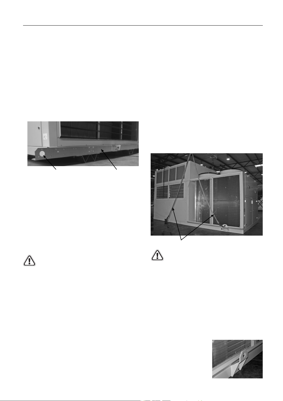
6 - TRANSPORT AND HANDLING
These machines must be unloaded and positioned by a specialist
handling company using the appropriate, standardised tools.
Before handling, check that the path leading to the installation
location is accessible and free from obstacles.
The unit must be handled with care to avoid transport damage.
Thus we recommend:
- Do not dispose of the pallet or the packaging materials until
the unit is in its fi nal location.
- For transport in a container, one must be selected that has
an easy load and unload to the installation location.
Optionally, the unit may have skids that allow the units to
be slid over the fl oor so that the container would be easily
removable (except with assemblies MC1, MWC1 and MRC1).
These skids make transport pallets unnecessary.
● Discharging to the same plane using skids (optional):
This method will be used only when it is possible to place the
transport box (trailer, maritime container, etc.) at the same
height as the discharging platform (for example, a dock).
To do so, each skid will be gripped by the points indicated in
the previus image, so that it can be pulled from the unit to be
extracted from the box.
Once the unit is discharged, it must be freed from the grips
and the skids so that the inserts available for the silent-blocks
can be accessed. Both are fi xed to the crossbar using M10
screws (hex. key 17).
● Discharge via crane:
A rocker arm, as well as approved cloth slings, both suitable for
the dimensions and weight of the unit, must be used in order
to carry out the work safely and without causing damage to the
units or to workers.
These slings will be hooked to the two grips located on each
crossbar. Make sure that the unit is protected from contact
with the hooks to prevent damage to the housing.
Gripping point
The unit can be discharged using a crane with a rocker arm
and cloth slings by using a forklift truck if it is done on the side
of the transport box. If the unit has transport skids at the same
height of the transport box, the unit can be discharged simply
by pulling on the skids at the points set out for them.
When using any of the three above methods, it is always
mandatory to grasp the unit by the points intended for that
purpose, as described in this chapter.
Any handling of the unit by other means or by gripping points
diff erent from those described here may be dangerous for both
the unit and the personnel who are carrying out the discharging
or transport work.
Always check the weight of the unit and verify that the
discharging method used is approved for handling
that weight.
● Discharge via forklift truck:
The unit is designed to be transported safely by using a forklift
truck. The forks of the forklift truck must come in on the side of
the unit, ensuring that the centre of gravity of the unit remains
within the forks, because a misbalance in the transport may
cause the unit to turn over and fall from the forklift truck.
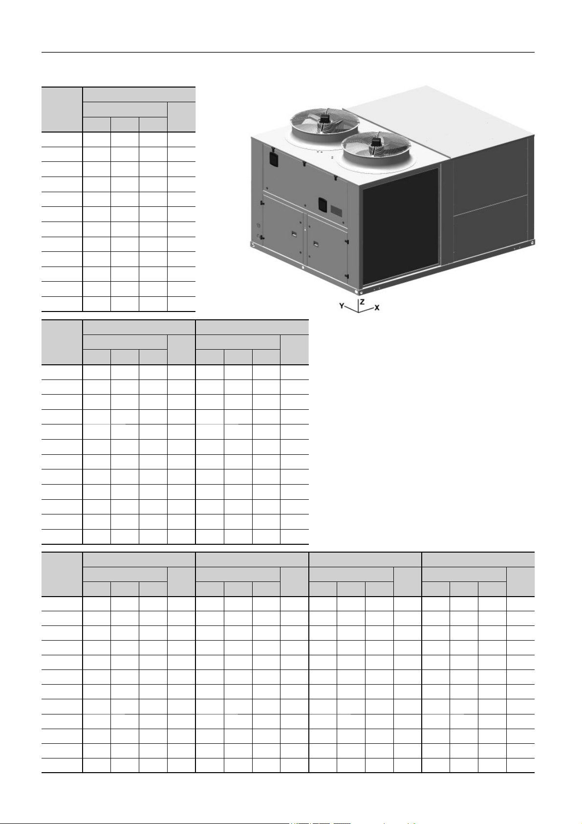
Note: please see the weight and the gravity centre coordinates
of each model stated in the following page.
The recommended length for the forks will be bigger than the
unit width, so that the entire weight-bearing structure of the
unit can be supported on the forklift truck. This also prevents
the possible introduction of the truck’s fork into functional parts
of the unit that may cause damage to the unit.
The standards and recommendations of the forklift truck
must also be respected with regards to the maximum load,
inclination of the fork carriage, elevation of the load for
transport, and, in particular, the maximum speed.
Skid
Cloth slings with rings
Do not raise any of the units by points outside of
those specifi ed here. In particular, do not raise them
by the traction points of the skids.
The unit must be lifted and fixed with care and without
inclination (maximum inclination 15º), since it could harm its
operation.
The centre of gravity is not necessarily in the middle of the unit
and the forces applied to the slings are not always identical.
Please consult the weight and the centre of gravity of each
model stated in the following page.
After the placing of the unit, it is recommended to remove the
grips as they can be a hindrance for maintenance. Put the
grips back in case of unit transport. The grips are fi xed to the
crossbar using M10 screws (hex. key 17).
Unit with condensates pan in the outdoor circuit:
With the optional condensates
pan in the outdoor circuit, the
units have 2 special grips
(in the outdoor unit), which
project 98 mm on the crossbar,
whereas they preserve the
original grips in the indoor unit.
6
Page 7
6 - TRANSPORT AND HANDLING
6.1 Centres of gravity
M0 assembly
50EN/EH
415
420
480
485
540
600
650
720
840
960
1100
1200
50EN/EH
415
420
480
485
540
600
650
720
840
960
1100
1200
Centre of gravity
X(mm) Y(mm) Z(mm)
1.449 1.069 810 1.703
2.135 1.056 667 1.926
1.435 1.057 783 1.726
2.107 1.057 665 1.951
2.097 1.060 654 1.950
2.063 1.062 643 1.999
2.135 1.025 783 2.213
2.041 1.028 740 2.264
2.075 1.020 772 2.390
2.081 1.024 764 2.487
2.933 1.097 763 2.998
2.895 1.094 742 3.111
Weight
(kg)
MS assembly MA / ME assemblies
Centre of gravity
X(mm) Y(mm) Z(mm) X(mm) Y(mm) Z(mm)
1.491 1.113 815 1.779 1.528 1.146 799 1.856
2.200 1.104 690 2.019 2.242 1.089 655 2.247
1.477 1.100 790 1.802 1.513 1.132 775 1.879
2.174 1.106 689 2.043 2.212 1.093 652 2.230
2.162 1.107 677 2.042 2.201 1.095 642 2.222
2.127 1.107 666 2.091 2.167 1.095 630 2.319
2.230 1.001 823 2.325 2.239 1.060 771 2.617
2.135 1.099 780 2.377 2.147 1.064 727 2.667
2.172 1.102 821 2.503 2.179 1.056 760 2.790
2.169 1.092 802 2.600 2.186 1.059 753 2.885
2.954 1.094 743 3.131 3.047 1.137 747 3.368
2.994 1.094 758 3.244 3.009 1.133 726 3.481
Weight
(kg)
Centre of gravity
Weight
(kg)
50EN/EH
415
420
480
485
540
600
650
720
840
960
1100
1200
MC0 assembly MRC0 assembly MC1 / MWC1 assemblies MRC1 assembly
Centre of gravity
X(mm) Y(mm) Z(mm) X(mm) Y(mm) Z(mm) X(mm) Y(mm) Z(mm) X(mm) Y(mm) Z(mm)
1.566 1.181 785 1.954 1.528 1.214 764 2.051 1.625 1.119 1.073 2.105 1.528 1.142 1.060 2.173
2.242 1.081 645 2.273 2.170 1.039 628 2.383 2.507 1.156 924 2.459 2.545 1.151 929 2.560
1.552 1.168 763 1.977 1.515 1.200 744 2.074 1.610 1.108 1.047 2.128 1.570 1.131 1.035 2.196
2.212 1.085 642 2.298 2.142 1.043 626 2.406 2.492 1.158 926 2.483 2.531 1.154 931 2.586
2.201 1.088 632 2.297 2.282 1.089 617 2.404 2.472 1.158 910 2.500 2.519 1.153 917 2.605
2.167 1.088 620 2.345 2.256 1.089 605 2.450 2.470 1.148 891 2.542 2.516 1.144 899 2.649
2.239 1.050 758 2.621 2.307 1.054 740 2.772 2.429 1.136 1.065 2.723 2.476 1.134 1.057 2.842
2.147 1.054 715 2.671 2.217 1.058 701 2.828 2.346 1.129 1.019 2.823 2.397 1.127 1.015 2.949
2.179 1.046 747 2.794 2.217 1.051 729 2.965 2.375 1.129 1.032 2.946 2.393 1.127 1.026 3.088
2.186 1.049 740 2.889 2.223 1.054 721 3.071 2.372 1.124 1.029 3.076 2.391 1.122 1.023 3.231
3.047 1.127 734 3.378 3.192 1.126 717 3.587 3.313 1.184 3.378 3.532 3.419 1.178 3.166 3.711
3.009 1.123 713 3.491 3.154 1.123 698 3.700 3.279 1.183 3.403 3.645 3.385 1.178 3.195 3.824
Weight
(kg)
Centre of gravity
Weight
(kg)
Centre of gravity
Weight
(kg)
Centre of gravity
Weight
(kg)
7
Page 8

6 - TRANSPORT AND HANDLING
6.2 Weight overview (kg)
Weight of the various assemblies (kg)
50EN/EH 415 420 480 485 540 600 650 720 840 960 1100 1200
M0 assembly (standard)
MS assembly
MA / ME assemblies
MC0 assembly
MRC0 assembly
MC1 / MWC1 assemblies
MRC1 assembly
Weight supplement from the main options (kg)
50EN/EH 415 420 480 485 540 600 650 720 840 960 1100 1200
Pre-assembly roofcurb
PCH065
PCH080
Gas
burner
module
Wheel
recovery
module
Water coil (empty)
Supply plug-fan
Supply centrifugal fan
Return plug-fan
Return centrifugal fan (MC1 / MRC1)
Insulation
M0 50mm
Opacimetric fi lters
PCH105
PCH130
PCH160
PCH210
Wheel 1500
Wheel 1800
Wheel 2000
High pressure
Low pressure
Extra low pressure
Extra extra low pressure
High pressure
Low pressure
M0
MC0 / MRC0 / MA / ME
MC1 / MRC1 / MWC1
MS
Burner module
Wheel recovery module
1.703 1.926 1.726 1.951 1.950 1.999 2.213 2.264 2.390 2.487 2.998 3.111
1.779 2.019 1.802 2.043 2.042 2.091 2.325 2.377 2.503 2.600 3.131 3.244
1.856 2.247 1.879 2.230 2.222 2.319 2.617 2.667 2.790 2.885 3.368 3.481
1.954 2.273 1.977 2.298 2.297 2.345 2.621 2.671 2.794 2.889 3.378 3.491
2.051 2.383 2.074 2.406 2.404 2.450 2.772 2.828 2.965 3.071 3.587 3.700
2.105 2.459 2.128 2.483 2.500 2.542 2.723 2.823 2.946 3.076 3.532 3.645
2.173 2.560 2.196 2.586 2.605 2.649 2.842 2.949 3.088 3.231 3.711 3.824
290 385 290 385 385 385 385 385 385 385 475 475
-- 414 -- 414 414 -- -- -- -- -- -- --
-- 440 -- 440 440 440 440 440 440 440 -- --
-- 468 -- 468 468 468 468 468 468 468 -- --
-- 504 -- 504 504 504 504 504 504 504 520 520
-- 555 -- 555 555 555 555 555 555 555 571 571
-- 600 -- 600 600 600 600 600 600 600 616 616
715 880 715 880 880 880 896 896 896 896 -- --
-- 901 -- 901 901 901 917 917 917 917 -- --
-- 928 -- 928 928 928 945 945 945 945 -- --
43 67 43 67 67 67 82 82 82 82 82 82
-- -- -- -- 132 104 41 41 65 65 40 40
-29 -29 -29 -29 -23 -16 -16 -16 -14 -14 -15 -15
-23 -23 -23 -23 -- -23 -23 -23 -23 -23 -40 -40
-- -- -- -- -- -- -- -- -- -- -51 -51
-105 -81 -105 -81 -68 -96 -120 -112 -113 -113 24 24
22 22 22 22 -- 33 33 44 44 44 -- --
-- -- -- -- -23 -23 -- -23 -23 -- -41 -41
-17 -16 -17 -16 -34 -27 -15 -44 2 2 96 96
297 319 297 319 319 319 361 361 361 361 404 404
228 245 228 245 245 245 272 272 272 272 302 302
311 325 311 325 325 325 368 368 368 368 406 406
262 282 262 282 282 282 316 316 316 316 353 353
-- 81 -- 81 81 81 108 108 108 108 124 124
14 17 14 17 17 17 17 17 17 17 -- --
87 84 87 84 84 84 116 116 116 116 137 137
Electrical heaters (kW)
Weight of module (kg)
8
27 36 45 54 72 90
19 24 29 34 48 58
Centrifugal fans (kW)
Weight of motor (kg)
0,75 1,1 1,5 2,2 3 4 5,5 7,5 11 15 18,5 22
10 13 16 21 24 27 40 48 75 94 124 141
Page 9
7 - POSITIONING AND INSTALLATION
7.1 Choice of location
When choosing the location, whatever may be the selected
fashion, the following precautions have to be taken into
consideration:
● It is mandatory to comply with norm EN 378-3 on Safety and
Environmental Requirements. Part 3: “In situ” installation and
protection to people.
● It is necessary to check that the structure supports the unit’s
weigh (please consult the weight in paragraph “ Weight
overview”).
● The area where the unit will be located must be perfectly
accessible for cleaning and maintenance operations (please
consult the “Recommended service clearance”). Leave
enough space for air circulation around the unit.
● Since the unit is designed to work outdoors, some specifi c
installation norms must be followed:
- The unit will be located on the roof of the premises. If it is
foreseen that it will work more on heating than on cooling, it
is preferable to direct the coil towards the sun. If little work
on heating is foreseen, choose North direction.
- Avoid placing obstacles in the air supply or return. No
obstacle may impede the air aspiration into the coils. Do not
fi x the outdoor coil side in the predominant wind direction.
- Do not install the unit in a closed enclosure or in conditions
that originate air recirculation.
- The chosen location must not fl ood and must be above the
average height the snow reaches in that region.
always in observation of the handling standards that have been
described, below is a proposed assembly sequence that may
facilitate the operation, keeping in mind that the sequence
performed in the installation shall be the one most suitable to th e
solution chosen for each particular case based on the existence
(or lack thereof) of brick frames, type of silent-blocks used, etc.
In the event of assembling directly on silent-blocks to the ground,
it is recommended that a template of the unit’s footprint with the
anchoring points of the silent-blocks be made, as described in
the paragraph “Preparation of the ground”.
With the help of the crane or the forklift truck, the unit will be
raised to a suffi cient height that the silent-blocks can be screwed
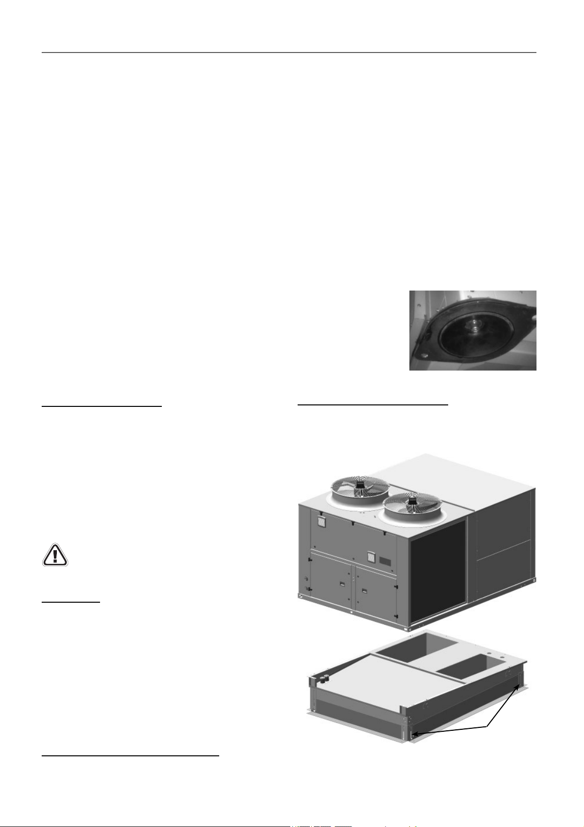
into its base. The 4 silent-blocks of the corners must remain
oblique and the interiors perpendicular to the unit.
M12 metric threads have been provided for their placement in
the supports indicated in the following section “Anchorage for
antivibrators”. A hex key 19 or Allen wrench 10 will be used for
this operation based on the type of screw used.
This image shows how
the silent-block option
that can be supplied for
this unit is fi xed to the unit.
Preparation of the ground
It is necessary to ensure that the surface where the unit is going
to be installed in completely fl at. Any defect in the preparation of
the unit support surface translates into stresses on the structure,
which may result in its deformation. The unit must be perfectly
level when installed.
These units can be installed on the fl oor or on a brick curb or steel
profi le. Based on the fi xing solution defi ned in the installation
project, it will be necessary to plan the placement in the base of
threaded rods in the expectation that the unit supports can be
fi xed later on. To do so, it is recommended that a template be
made with the heights corresponding to the fi xings.
Foresee appropriate damping devices in these fi xings
to ensure that noise and vibration transmission
is avoided (refer to the section “Anchorage for
antivibrators”).
Sound Level
These units are designed to work with a low acoustic level. In any
case, the following must be taken into account for the design of
the installation: the outdoor environment for acoustic radiation,
the type of building for the noise transmitted by air, the solid
elements for the transmission of vibrations.
To reduce transmission through solid surfaces to the maximum, it
is very advisable to install shock absorbers between the ground
or structure and the unit frame. If necessary, a study must be
commissioned to an acoustic technician.
Note: Sound levels can be found in the technical brochure of
this series.
Antivibrators assembly (silent-blocks)
Although the installer is the one who must decide on a case-bycase basis the best way to place the unit in the ultimate location,
Preassembly roofcurb (optional)
Optionally, standardised pre-assembly roofcurb made of
galvanised steel panelling with polyester paint and thermally
insulated with adjustable heights can be supplied.
Levelling
system
Important: All of the necessary information for the installation of
these roofcurbs is available in the specifi c instruction brochure
on roofcurbs, No. 12.62 (supplied with the roofcurb).
9
Page 10
7 - POSITIONING AND INSTALLATION
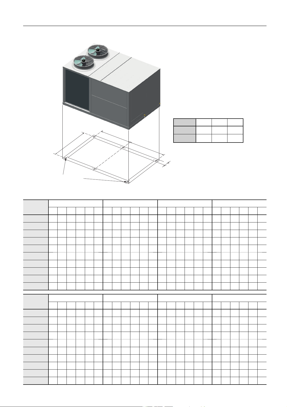
7.2 Anchorage for antivibrators
50EN/EH 415 to 960
R4
B
R1
R2
M12 (rivet nut)
A
R5
50EN/EH A (mm) B (mm) C (mm)
415 / 480
420 / 960
1.545 2.095 104
2.290 2.095 104
A
R6
C
R3
Reactions in the supports for the various assemblies (kg)
50EN/EH
415
420
480
485
540
600
650
720
840
960
50EN/EH
415
480
420
485
540
600
650
720
840
960
M0 Assembly MS Assembly MA Assembly ME Assembly
R1 R2 R3 R4 R5 R6 R1 R2 R3 R4 R5 R6 R1 R2 R3 R4 R5 R6 R1 R2 R3 R4 R5 R6
290 417 172 272 399 154 278 423 179 284 429 185 269 432 188 295 458 214 269 432 188 295 458 214
322 476 208 294 447 179 308 483 217 309 484 217 338 543 257 328 533 247 338 543 257 328 533 247
301 426 174 276 401 149 290 432 181 288 431 180 281 441 190 299 459 208 281 441 190 299 459 208
332 481 204 304 453 176 317 488 213 319 491 215 342 538 246 335 531 239 342 538 246 335 531 239
333 480 201 307 454 175 319 488 210 322 491 213 342 535 242 337 530 237 342 535 242 337 530 237
349 492 198 323 466 172 335 500 207 338 502 210 366 558 244 360 553 238 366 558 244 360 553 238
381 557 249 327 503 195 385 594 295 310 520 220 407 645 310 371 609 275 407 645 310 371 609 275
412 569 231 359 516 177 382 571 240 379 568 237 440 655 288 407 623 255 440 655 288 407 623 255
429 604 256 367 541 193 390 600 262 390 600 261 454 689 314 412 648 273 454 689 314 412 648 273
423 598 254 364 539 195 411 627 275 402 619 267 466 711 326 425 671 286 466 711 326 425 671 286
MC0 Assembly MRC0 Assembly MC1 / MWC1 Assemblies MRC1 Assembly
R1 R2 R3 R4 R5 R6 R1 R2 R3 R4 R5 R6 R1 R2 R3 R4 R5 R6 R1 R2 R3 R4 R5 R6
261 444 199 310 493 248 275 455 186 348 528 259 282 499 256 293 510 267 317 507 222 344 534 249
345 552 262 330 537 247 396 595 272 348 547 224 273 568 326 314 610 367 275 593 352 315 633 391
272 453 201 314 494 243 288 465 188 352 529 253 293 508 257 297 512 261 309 516 243 329 536 263
355 557 256 342 544 244 406 599 266 360 554 221 279 573 324 323 617 368 281 598 350 323 641 393
356 556 253 346 545 242 351 581 285 341 571 275 286 577 321 330 621 365 286 603 350 329 645 392
372 567 249 362 556 238 365 592 283 355 582 273 295 591 330 332 627 367 296 617 358 331 652 394
411 650 315 368 606 271 413 685 352 370 643 309 334 638 346 363 667 375 335 667 377 363 695 405
444 660 292 403 619 251 447 698 329 407 657 289 375 664 337 399 688 361 376 695 369 399 718 392
459 694 319 409 644 269 472 734 348 424 686 300 382 693 361 407 718 385 395 728 385 419 752 409
471 717 331 422 668 282 485 759 362 438 712 314 402 727 378 423 747 399 417 764 404 437 784 425
10
Page 11
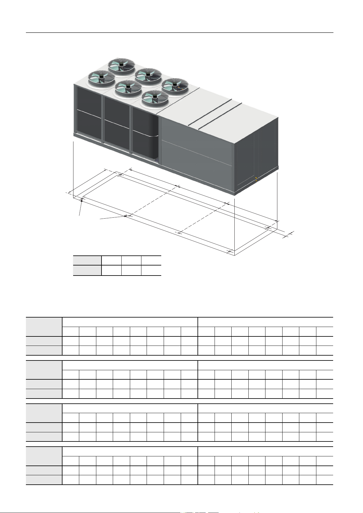
7 - POSITIONING AND INSTALLATION
7.2 Anchorage for antivibrators
50EN/EH 1100 and 1200
R5
A
B
R1
M12 (rivet nut)
50EN/EH A (mm) B (mm) C (mm)
1100 / 1200
Reactions in the supports for the various assemblies (kg)
50EN/EH
1100
1200
R1 R2 R3 R4 R5 R6 R7 R8 R1 R2 R3 R4 R5 R6 R7 R8
326 520 409 252 322 515 405 248 338 538 433 268 332 532 427 262
346 550 415 256 340 544 409 250 343 547 460 285 337 541 453 279
R2
2.027 2.095 104
M0 Assembly MS Assembly
R6
R3
A
R7
A
R8
C
R4
50EN/EH
1100
1200
50EN/EH
1100
1200
50EN/EH
1100
1200
MA Assembly ME Assembly
R1 R2 R3 R4 R5 R6 R7 R8 R1 R2 R3 R4 R5 R6 R7 R8
330 536 475 288 357 564 502 316 330 536 475 288 357 564 502 316
349 567 481 292 375 592 507 318 349 567 481 292 375 592 507 318
MC0 Assembly MRC0 Assembly
R1 R2 R3 R4 R5 R6 R7 R8 R1 R2 R3 R4 R5 R6 R7 R8
334 542 480 293 354 562 500 313 327 533 553 340 347 553 573 361
355 572 487 297 372 590 504 315 346 563 560 345 364 580 578 363
Montaje MC1 MRC1 Assembly
R1 R2 R3 R4 R5 R6 R7 R8 R1 R2 R3 R4 R5 R6 R7 R8
274 465 555 334 343 534 624 403 269 459 618 375 336 526 685 442
290 491 563 338 360 561 633 408 285 484 627 380 353 552 695 448
11
Page 12
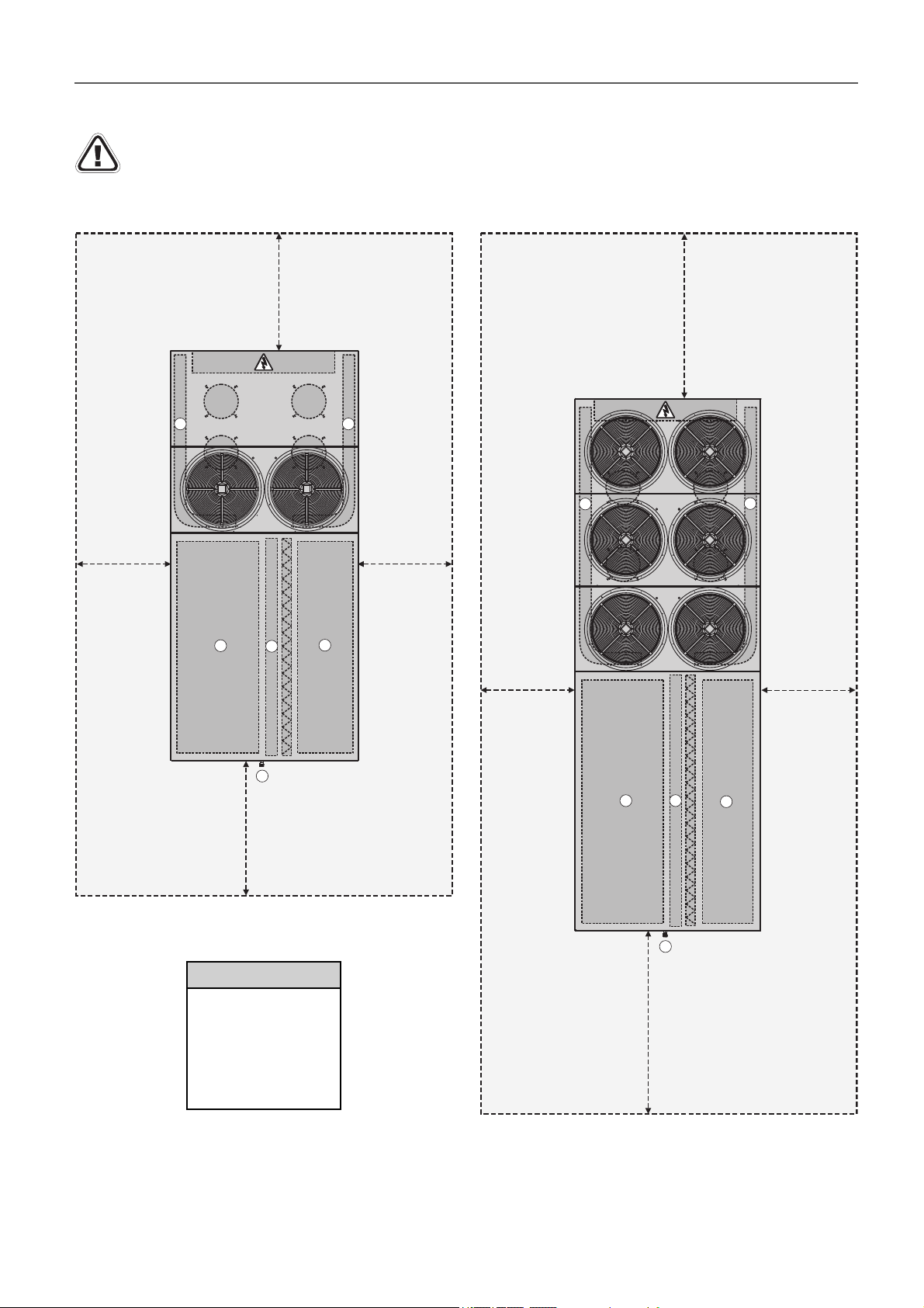
7 - POSITIONING AND INSTALLATION
7.3 Recommended service clearance
50EN/EH units are not designed to have overhead obstruction.
50EN/EH - 415, 420, 480, 485, 540, 600, 650, 720, 840 and 960
2000m m
2 2
1500m m 1500m m
3
1
4
50EN/EH - 1100 and 1200
2
3000m m
2
2500mm
LEGEND
Indoor air coil
Outdoor air coil
Air supply
Air return
Condensates outlet
1500m m 1500m m
5
3
1
5
4
3500mm
12
Page 13
8 - ELECTRICAL CONNECTION
8.1 Installation norms
Important: All connections in the site are the
responsibility of the installer. These connections are
always made as per the current regulation. Always refer
to the wiring diagram provided with the unit.
The installer must provide electrical circuit protections
according to the eff ective legislation.
V-220005
To prevent electrical shocks, make all electrical
connections before energizing the unit. Check that the
automatic switch is closed. Omitting this can cause
personal damage. Make the ground connection before
any other electrical connection.
8.2 Power supply
Verify that power supply agrees with the unit name plate and
that the voltage remains constant.
Warning: Operation of the unit with an incorrect supply voltage
or excessive phase imbalance constitutes misuse which will
invalidate the manufacturer’s warranty. If the phase imbalance
exceeds 2% for voltage, or 10% for current, contact your local
electricity supplier at once and ensure that the unit is not
switched on until corrective measures have been taken.
Voltage phase imbalance (%)
% imbalance =
Example:
On a 400 V - 3 ph - 50 Hz power supply, the individual phase
voltages were measured with the following values:
AB = 406 V; BC = 399 V; AC = 394 V
Average voltage = (406+399+394)/3=1199/3 = 399.7 i.e. 400 V
Calculate the maximum deviation from the 400 V
average:
(AB) = 406 - 400 = 6 -> % = 100 x 6 / 400=1.5
(BC) = 400 - 399 = 1 -> % = 100 x 1 / 400=0.25
(CA) = 400 - 394 = 6 -> % = 100 x 6 / 400=1.5
Important: It is the responsibility of the installer to protect the
unit from overvoltage coming from the mains or voltage spikes
caused by lightning. Depending on the geographic location
and the type of mains network (buried or overhead), a lightning
rod needs to be installed. Check the local electrical codes and
regulations. Failure to comply with the requirements of standards
in force in the country of installation will void the warranty.
100 x max. deviation from average voltage
average voltage
Moteur
Motor
8.3 Wire sizing
Wire sizing is the responsibility of the installer to suit the
characteristics of the installation site and comply with applicable
regulations.
To perform the electric installation of the unit (cable glands,
wire sizing and their calculations, protections, etc.), refer to the
information provided in:
● The technical brochure of this series.
● The name plate data.
● The wiring diagram included with the unit.
● Norms in eff ect that regulate the installation of air conditioning
units and electrical receivers in the country of installation.
Wiring must be selected based on:
● The maximum power input, taking into account all the options
it features (refer to the technical brochure and the name plate).
● The distance between the unit and its power source.
● The protection to be placed at the power source.
● Neutral operating conditions.
● The electrical connections (refer to the wiring diagram
provided with the unit).
● The temperature the wiring is exposed to;
● The fi tting method.
After wire sizing has been completed, the installer must verify the
appropriate means of connection and defi ne any modifi cations
necessary on site.
Power cable access routing
The power cables can be routed into the electrical box for the
units:
● Via the panel located under the electric panel.
● Via the base of the unit
It is important to check that the power cable bend radius is
compatible with the connection space available inside the
electric panel.
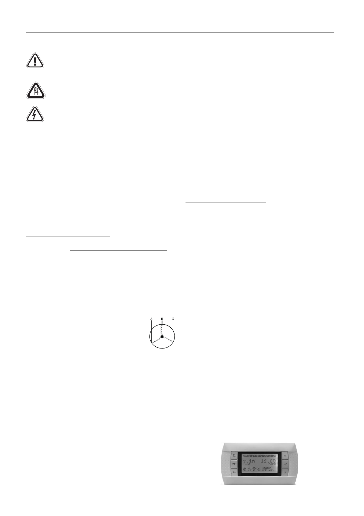
8.4. CARRIERrtc electronic control
The CARRIERrtc control is basically composed of a μPC
MEDIUM control plate, a pGD1 graphical terminal, a TCO user
terminal (optional), and sensors.
Please refer to this control brochure to obtain more detailed
information about its operation.
pGD1 terminal:
This terminal, installed in the electric panel of the machine,
allows for:
● The initial programming of the unit.
● The modifi cation of the operating parameters.
● Stopping/starting the unit.
● The selection of the operating mode.
● Setting the setpoints.
● The on-screen view of the controlled variables and the values
measured by the sensors.
● The on-screen view of the description of the active alarms
and the alarms log.
13
Page 14
8 - ELECTRICAL CONNECTION
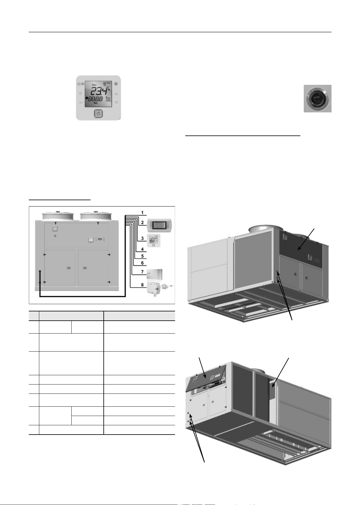
TCO user terminal (optional):
This terminal can be installed on the electric panel, instead of
pGD1 terminal. In this case, the remote connection of the pGD1
terminal is posible.
Optionally, these units can change the electronic control to
CARRIERrtc medium (available for models 415 to 720). This
control is fi tted with the TCO terminal as standard, and the pGD1
terminal as an option. Consult the technical brochure.
Note: for more detailed information on these controls, please
refer to their brochures.
Customer connection
8.5 Electric panel
All units include a fully wired electrical panel, with forced
ventilation.
The access door is insulated to prevent condensation. This door
has hinges + quarter-turn latches.
These latches of stainless steel have triangular
insert 8 mm (supplied wrench). The closing is
done by rotating 90º (anti-clockwise): it brings
the latch to the locked position.
Position of the electric panel in the units
● Models 650 to 1200 include two fully wired electric panels:
- a main panel to which there is an electrical power supply,
- an auxiliary panel in which the optional elements of the
indoor circuit are connected.
Note: all models have a plug of 230 Vac in the main electric
panel.
50EN/EH - 415, 420, 480, 485, 540 and 600
No. 50EN/EH 415 to 1200
Main power
1
supply
Remote connection of pGD1
2
terminal (by default installed
on the electrical cabinet)
Connection of TCO user
3
terminal on the electrical
cabinet (optional)
4 Remote off /on (optional) 2 wires
5 General fault signal (optional) 2 wires
Circulation pump signal for
6
HWC (antifreeze sec.) (opt.)
Ambient
7
probe
8 Air quality sensor (opt.) 3 wires
400 III (±10%)
NTC (std) 2 wires
RS485 (opt.)
3 wires + ground
telephone cable 6 wires standard
(RJ12 connector)
2 wires for power supply 230V + 1
shielded cable for communication
type AGW20 / 22 (1 braided pair
+ drainwire + shielding)
1 wire
5 wires
Electric power supply inputs
50EN/EH - 650, 720, 840, 960, 1100 and 1200
Main panel
Main panel
Auxiliary panel
In this case, it´s posible to install the TCO terminal on the electrical cabinet.
It’s necessary that the terminal uses the same power supply that the
control board.
Up to four RS485 ambient sensors can be connected in series on the
fi eld-bus of the control board.
14
Electric power supply inputs
Page 15
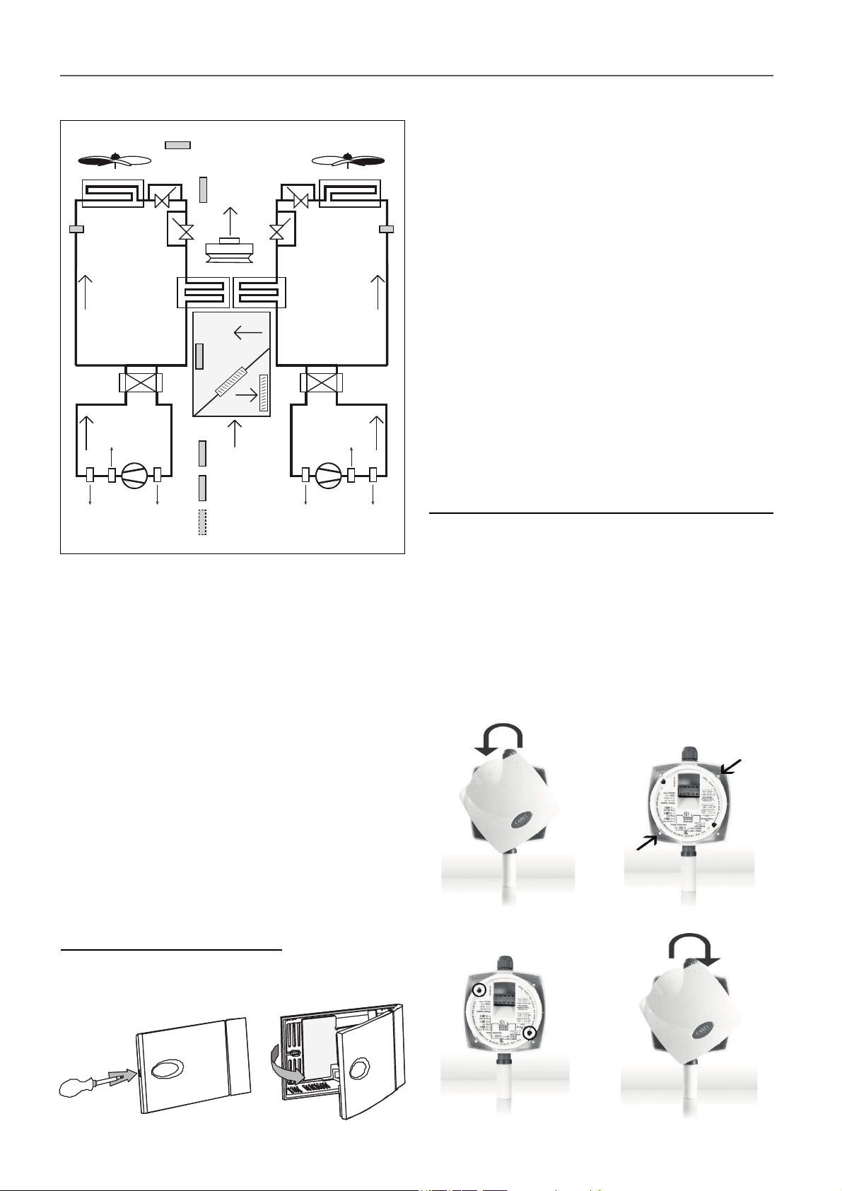
8 - ELECTRICAL CONNECTION
p
)
8.6 Location of sensors (2 circuits)
B2
Outdoor temperature probe
Outdoor fan
Outdoor coil
B7
Press. transducer
in the outdoor
coil cir. 1
Indoor coil
CIRCUIT 1 CIRCUIT 2
Reversing
valve
(heat pump)
Discharge T
klixon switch
Compressor
Low pressureHigh pressure
B3
Supply
air probe
Indoor fan
Fresh
air
B4
Mixing
probe
Extraction
B1
Return air probe
B5
Ambient air probe
B10
Air quality
robe (opt.
Note: If the unit needs the outdoor humidity probe (used with
enthalpic or thermoenthalpic free-cooling), this one will be
connected in B5 in the place of the NTC ambient probe. In this
case it is necessary to use a RS485 ambient temperature probe
connected on the Field-bus.
The outlet probe (B3) and the mixing probe (B4) can be replaced
by RS485 enthalpic probes for calculation of the cooling and
heating capacities (optional).
Outdoor fan
Outdoor coil
Press. transducer
Indoor coil
Compressor
Low pressure High pressure
B12
in the outdoor
coil cir. 2
Reversing
valve
(heat pump)
Discharge T
klixon switch
● Fasten the rear of the sensor case to the panel or the wall (for
fastening the case, use the screws supplied with the fastening
kit, paying attention to use the proper spacers, to not damage
the sensor’s electronics).
● This probe must be fastened to the panel or the wall of the
room to be conditioned, at ca. 1.5 m height.
● Close the sensor with the top cover by pressing lightly.
Electrical connection
● Make the electrical connection according to the unit
confi guration:
- NTC probe (B5 - connector J3) : with 2 x 1,5 mm
2
section
cable, within a maximum distance of 30 meters.
- 1 to 4 RS485 probes of temperature or temperature+
humidity (connector J10): with AWG20 section cable, single
braided pair preferably shielded with drain wire + Power
supply 24 Vac (2 wires).
Note: in the case of more than one probe, connection of the
probes in series, in the RS485 network. Please, refer to the
CARRIERrtc control manual.
Connection of the outdoor humidity probe (optional)
The outdoor humidity probe (optional on B5 - connector J3),
necessary for the enthalpic and thermo-enthalpic free-cooling,
must be installed on-site, on the hood of the fresh air intake.
● Open the case by turning the top cover anticlockwise (fi g1).
● Fasten the rear of the sensor case to the side panel of the
hood (use the screws supplied together with the probe) placing
the screws in the holes provided (fi g.2).
● Make sure that the screws that hold the board protective cover
are fastened tightly (fi g.3).
● Close the sensor by turning the cover clockwise (fi g.4).
8.7 Sensors connection by the costumer
The client must connect on-site the following probes:
● Ambient NTC (standard) or RS485 (optional).
● Air quality (optional).
● Outdoor humidity (optional).
These probes are supplied inside the main electric panel of the
50EN/EH unit.
Please refer to the wiring diagram and the CARRIERrtc
control brochure, both provided with the unit.
Connection of the ambient probe
● Open the case using a fl athead screwdriver in the slot, paying
extra care not to damage the electronic parts.
(fi g.1)
(fi g.2)
(fi g.3) (fi g.4)
15
Page 16
8 - ELECTRICAL CONNECTION
Then the electrical
connection of the probe
should be made.
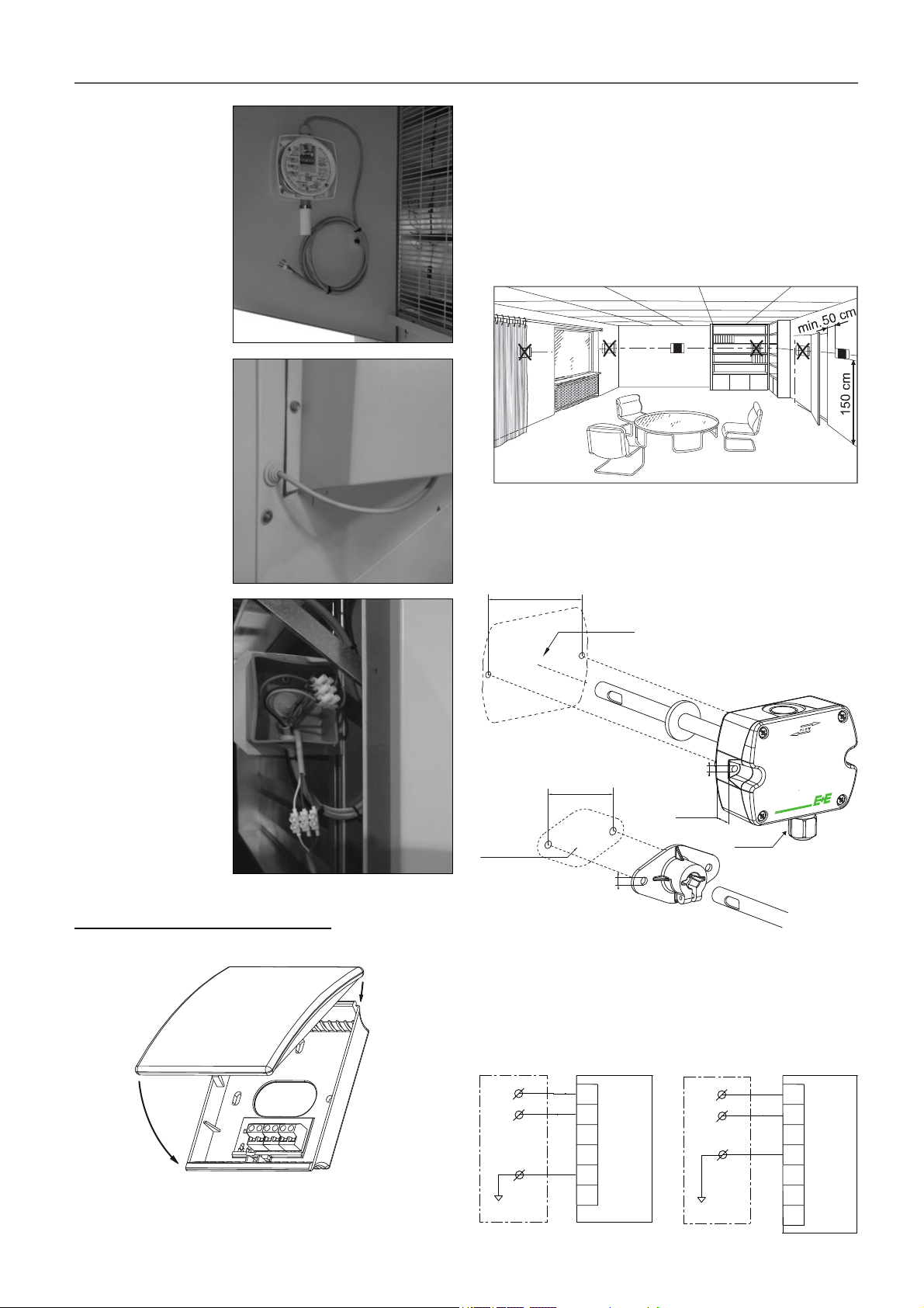
The installer only has to
insert the cable through
the feedthrough for
wiring it in the PVC box
located inside the unit,
next to the servomotor.
● It should never be mounted:
- On outside walls.
- In niches or behind curtains.
- Above or near heat sources or shelves.
- On walls covering heat sources such as a chimney.
- In the radiation range of heat sources and lighting bodies
e.g. spotlights.
- In areas exposed to direct solar radiation.
Duct-mounted
This version can be connected to the air duct in these two ways:
The position of the
terminal box depends
on the assembly
selected for the unit.
Connection of the air quality probe
Installation in the environment
● This probe must be fi xed to the interior wall of the room to be
conditioned, at ca. 1.5 m height in the room and at least 50
cm from the next wall.
±0.3
90
mm
±0.11
“
3.54
Ø > 13mm
Ø > 0.51“
5mm
0.2“
19mm
0.75“
M16x1,5
Ø > 16mm
Ø > 0.63“
60
2.36
±0.3
mm
±0.11
“
6mm
0.24“
Electrical connection
This CO
probe (S13) is confi gured as analogue output 4…20
2
mA (0..2000 ppm), in the analogue input B10 of the control
board (connector J18).
Recommended cable section : 1,5 mm
2.
Environment: Duct-mounted:
Electric
panel
B10 (J18)
22
21
23
S13
+V
1
2
GND
3
RH
4
T
5
CO2
6
GND
Electric
panel
22
21
23
B10 (J18)
1
2
3
4
5
6
7
S13
+V
GND
GND
CO2
NC
Tpassive
Tpassive
16
Page 17
9 - FANS AND AIR DUCTS
9.1 Checks in the axial fans
● Before commissioning, check the blade rotation direction and
that the axis turns without strokes nor vibrations.
● Once running, check the operation conditions: pressures,
fl ows and consumptions.
● With electronic fans (standard), check that they adapt their
rotational speed based on the condensation or evaporation
pressure.
Note: Optionally these units can be supplied with two-speed
fans. Models 840 to 1200 do not comply with ErP regulation
(only for countries outside the European Union).
● Closing mode:
First rotate 90º (anti-clockwise): closing brings
the latch to the locked position. The door
cannot be opened.
9.3. Checks in the centrifugal fans (optional)
If the unit is equipped with centrifugal fans for the supply and/
or return air:
● Before commissioning, check the blade rotation direction and
that the axis turns without strokes nor vibrations.
● Once running, check the operation conditions: pressures,
fl ows and consumptions.
● The overlapping of characteristic curves of the fan and the
room is very important, so that the fl ows and pressures
provided to the duct network are as required.
9.2 Checks in the EC plug-fans
● Before commissioning, check the blade rotation direction and
that the axis turns without strokes nor vibrations.
● Once running, check the operation conditions: pressures,
fl ows and consumptions.
● The coupling of characteristic curves of the fan and the room
is very important, so that the fl ows and pressures provided to
the duct network are as required.
● The variable-speed plug-fans, both supply and return, have a
fl ow control pressostat. This pressostat comes from the factory
adjusted to the indicated fl ow. However, the fl ow for diff erent
conditions can be readjusted on site from the pGD1 graphic
terminal (please refer to the CARRIERrtc control brochure).
Note: The centrifugal supply fans do not comply with ErP
regulation (only for countries outside the European Union).
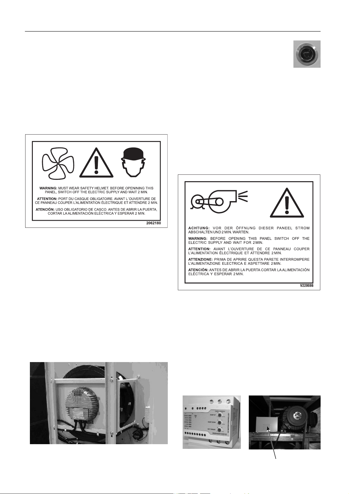
● Soft starter detail (optional):
The soft starter of the outlet fan extends the time to reach its
regular speed. This is mainly intended for installations with
fabric ducts however is always compulsory with motors with
an output of 15 kW and higher.
For motors up to 15 kW it is installed in the factory in the
relevant auxiliary or main electric panel (according to the
model). For larger motors it is installed next to the ventilation
group.
Motor output up to 15 kW Motor greater than 15 kW
Note: the access panel to the supply fan(s) is fi tted with hinges +
quarter-turn latches of stainless steel and triangular insert 8 mm.
Starter
17
Page 18
9 - FANS AND AIR DUCTS
Pulley and belt calibration
Attention: Before performing these operations, it is
necessary to verify that the unit is disconnected from
mains.
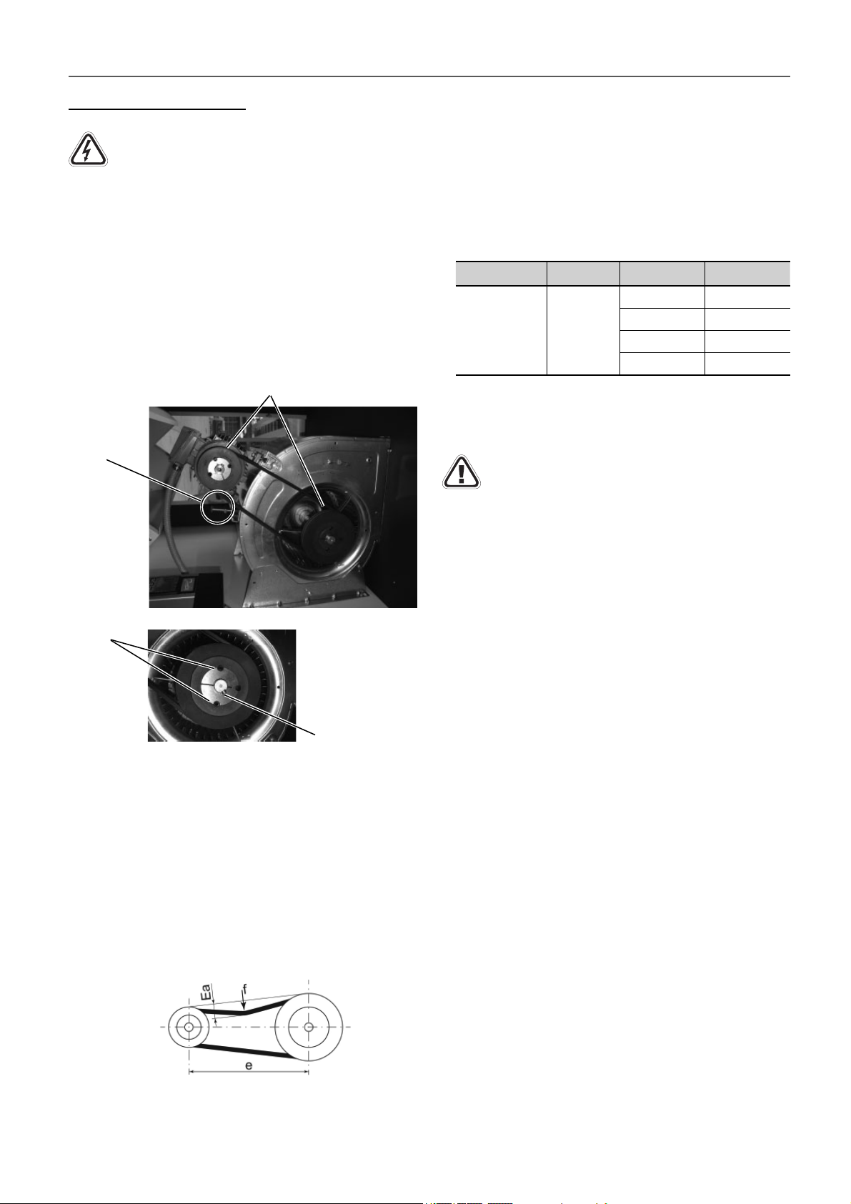
The centrifugal motorfans are coupled through pulleys and belts.
In these fans, the following must be taken into consideration:
Pulley alignment:
● The pulleys must be on the same plane, so it is important to
check them with the help of a ruler or a laser aligner.
● In case they are not aligned, remove the pulley screws, and
after removing the taper pin, the set of pulley and taper can
be slided over the axis (this action can be performed both in
the motor as well as in the fan).
Pulleys must stay on the same plane
Tensor
screw
- e = pulley centre distance in mm
- E = see table below for the value
- f = force applied
● At the centre of the centre distance “e”, apply a force “f”, as
determined in the table below, to each belt. Set the belt tension
to obtain the calculated defl ection “Ea”.
Belt type
SPZ 25
d (mm) E (mm)
f(N)
56 ≤ 71 2.45
< 71 ≤ 90 2.20
< 90 ≤ 125 2.05
125 1.90
Load to be applied per belt f (N)
Small pulley diameter (mm)
Belt deformation for a pulley centre distance of 100 mm - E (mm)
Important: During commissioning, the belt tension
must be checked after 48 hours of operation.
The belt tension must be checked in all cases and
before system start-up.
Pulley
screws
Taper pin
Belt tension:
After fi xing the pulleys on the same plane, the belt tension is
made by tightening the tensor screw.
Excessive tension on the belt can lead to premature wear on
the assembly. Insuffi cient belt tension can cause slippage,
overheating and premature wear of the belt.
It is essential to tension the belts using the “Defl ection test”
described below:
● The belt tension must be checked and corrected using a
suitable measuring instrument (tensiometer or dynamometer).
● “Ea” calculation:
- Ea = (e x E)/100 = deformation in mm for a pulley centre
distance of 100 mm
9.4 Air ducts connections
The air supply and return ducts must be calculated in accordance
with the nominal fl ow and the unit’s available pressure (refer to
the technical characteristics table).
The duct calculation and design must be made by qualifi ed
technical personnel.
It is advisable to take into consideration the following
recommendations:
● Curves in the fan supply outlet(s) must be avoided. It is
recommendable to have a straight section of duct measuring
approximately 1 metre. If it is not possible, they must be as
smooth as possible, using indoor defl ectors when the duct is
of large dimensions.
● When making the ducts, direction sharp changes must be
avoided since they can generate occasional pressure drops,
which aff ect the available pressure and the fl ow. The location
of discharge and aspiration grilles must be studied carefully to
avoid the air recirculation and the transmission and generation
of noises to the interior.
● Consideration should be given to the need to install fi lters
on the return ducts, taking into account any particles in
suspension existing which could settle inside the machine
(e.g. textile fi bres).
● Flexible connections must be made between the ducts and
the unit that avoid the noise and vibration transmission.
● No matter the type of ducts used, they must be isolated and
not be composed of materials that propagate fi re nor expel
toxic gases in the event of a fi re. The internal surfaces must
be smooth and should not pollute the air that circulates within
them. In any case, the eff ective legislation about this issue
must be respected.
18
Page 19
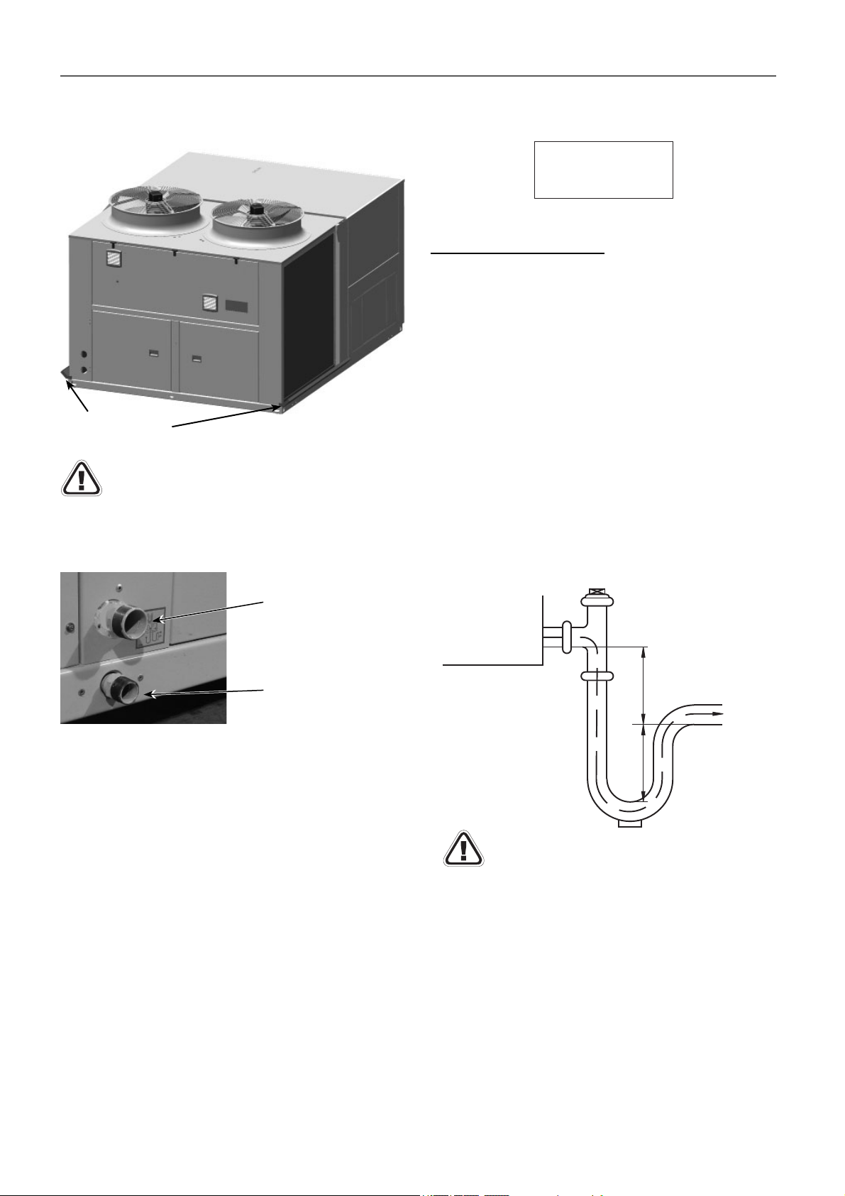
10 - CONDENSATE DRAIN
All models are equipped with a condensate drain pan in the
indoor circuit, with a bronze, gas threaded 1 1/4” M drain junction.
Outdoor circuit
pans (optional)
With outdoor temperatures which are lower than 0ºC
the necessary precautions must be taken to prevent the
water in the drain ducts from freezing.
In units where the outdoor condensates pan is optional, the
outdoor circuit drain (junction 1” M) is independent from the
indoor circuit drain. Do not connect both drains.
Important: the water drain pipe must be provided with a siphon
to avoid bad smell and water spills.
CONNECT SIPHON
METTRE SIPHON
PONER SIFON
Siphon installation norms
● Check that the condensate outlet is not clogged.
● Perform the assembly as per the scheme of the attached
starting diagram:
● Pan in overpressure:
It is installed to avoid the access through the drain piping of
bad smells.
● Pan in underpressure:
Besides the previous application, water must be sucked from
the pan:
- For the correct siphon design, the “A” height must be at
least twice that of the underpressure (mm.w.c) where the
condensate pan is placed.
- The drain piping must be slightly sloped to ease circulation
towards the drain.
- The original diameter of the piping must be respected. No
reduction can be made.
V220014
Indoor circuit
condensate
drain pan
Outdoor circuit
condensate drain
pan (optional)
Some options have their own pan with independent drain
junction, gas threaded:
● Cooling recovery circuit: 3/4” M in bronze.
● Rotary heat exchanger: 1” M in bronze.
● Gas burner: consult in the specifi c instruction brochure of
burners Nb 09.100 (supplied with the burner).
Condensates pan
in depression
Check the connection watertightness.
A
A
Siphon drain
Slight slope
5/1000
To drainage
19
Page 20
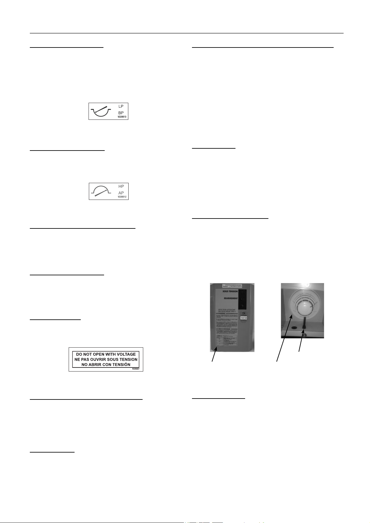
11 - SAFETY ELEMENTS
Low pressure pressostat
When connected to the compressor suction, it will stop its
operation when the pressure at that point goes down below the
tare value (caused by obstructions in the circuit, excessive dirt
in the fi lters, fan stop or ice formation in the evaporator).
This pressostat disconnects at 2 bar and is automatically
reactivated.
High pressure pressostat
Connected to the compressor discharge, it will stop its operation
when the pressure at that point reaches the setpoint. It
disconnects at 42 bar and it is automatically reactivated.
Magnetothermals for line protection
They are located at the beginning of the power lines for the
compressors and motor fan(s) to protect them.
Safety at the compressor
Temperature probe for the discharge from the compressor to
protect the unit with discharge temperatures greater than 135ºC.
Condensation and evaporation pressure control
This safety device, integrated in the control, enables managing
the outdoor fans when the units are working in cooling mode with
low outdoor temperatures (condensation control) or in heating
mode with high outdoor temperatures (evaporation control). This
aids the unit’s operation in all the seasons.
In the case of EC electronic fans, such as those that are found in
these units by default, speed control will be proportional based
on the average pressure measured by the pressure transducers
in the outdoor coils.
Anti-fi re safety
The electronic control can activate an anti-fi re safety device that
detains the unit when the return air surpasses a temperature
of 60°C (by default).
It cannot return to operation until the temperature has dropped
to below 40ºC.
Smoke detector (optional)
In accordance with standard NF S 61-961, this smoke detection
station uses a LED to indicate the installation status, and if the
probe detects the presence of smoke in the installation, it stops
the operation of the unit.
The station is installed in the factory in the main electric panel
or in the auxiliary electric panel (depending on the model). The
probe is placed on a pillar next to the supply fans.
Main door switch
By using a mechanical device, it impedes access to the electric
panel when the unit is with voltage.
Automatic switch in the control circuit
Magnetothermal switch that protects the operation circuit against
continuous surges as well as against high currents of short
duration (short circuits).
Defrost control
This safety device is intended to eliminate ice which could
accumulate in the outdoor coil when the unit is working in the
heating cycle. Defrosting is carried out by the control depending
on the value measured by the sensors on the outdoor coils and
the time set between defrosting operations.
Air inlet tube
Smoke detecting station Smoke detecting probe
Control of air fl ow
- The supply plug-fans (standard) adapt their speed to the
average fl ow measured by the diff erential pressure sensor
and the value set as a setpoint in the electronic control.
- For those units with centrifugal supply fans (optional), a
diff erential pressostat can be incorporated in order to measure
the variation in air fl ow. This pressostat allows the detection of
fan belt breakages, since the fan relay only detects operating
faults that have arisen in the motor. This pressostat is installed
in the factory in the main electric panel or in the auxiliary
electric panel (depending on the model). This safety device
is mandatory for units with electrical heaters and with gas
burners if the unit does not have the supply plug-fans.
20
Page 21
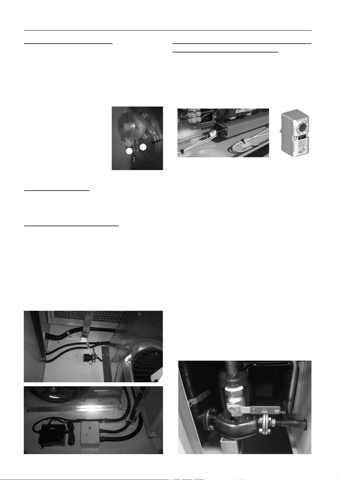
11 - SAFETY ELEMENTS
Clogged fi lter detector (optional)
Diff erential pressostat for detection of the fi lter clogging level.
The value for alarm signalling is set in factory, depending on
the fi lters selected for the unit.
The electronic control allows the settings selection for the
clogged fi lter alarm: only indication (by default) or unit stoppage.
Manual reset.
Pressure reading is done thanks to two intakes within the air
fl ow before and after the fi lter, such that a comparison is made
between the pressure of the inlet air
to the fi lter (positive) and the supply
air of the same to the other side of the
evaporating coil (negative).
This safety device is particularly
recommended with gas burner.
+
This pressostat is installed in the
factory in the main electric panel or in
the auxiliary electric panel (depending
on the model).
_
Remote alarm (optional)
CARRIERrtc control allows the management of a relay for
remote alarm signalling.
Refrigerant leak detector (optional)
The gas detector sensor is a device that signals leaks in
refrigerant.
When the loss of a certain concentration is detected, the sensor
sends the alarm to the control, which stops the unit and locally
activates a acoustic and visual signal.
This off ers the advantage of acting immediately to gas leaks,
guaranteeing the safety of persons who are in the proximity
thereof. Its installation complies with European regulations
F-GAS, EN378, and ASHRAE 15.
This sensor is installed next to the supply fan. In case of alarm,
it is reset manually.
Anti-freeze protection for low outdoor temperatures
(opcional equipment for GREAT COLD)
● Electrical heater for protecting the components of the electric
panel. This safety device is mandatory for an outdoor
temperature lower than -8°C WB. A reinforced electrical heater
is mandatory for a temperature lower than -16°C WB.
The electrical heater(s) is(are) activated when the thermostat
installed inside the electric panel detects that the temperature
drops below 5°C.
● Compressor with low-temperature protection using an
additional crankcase heater: mandatory for an outdoor
temperature lower than -8ºC WB.
Activation temperature: -8ºC WB.
● Dampers for the mixing box (optional) with springs for
automatic closing in the case of a cut in power. Mandatory
for an outdoor temperature lower than -8ºC WB.
Activation temperature: -8ºC WB.
● Electrical heater for anti-freeze protection of the mixing box
dampers (optional): mandatory for an outdoor temperature
lower than -12ºC WB.
Activation temperature: -12ºC WB.
● Hot water coil circuit (optional) with anti-freeze technology
based on the water temperature: mandatory for an outdoor
temperature lower than -20ºC WB.
This protection is made up of a circulation pump as well as
two probes inserted in the input and the output of the coil
Operation of the pump with GREAT COLD:
- Antifreeze protection: if the water temperature in the coil
drops below 4ºC, the control activates the pump and the
3-way valve opens to 100%. The pump stops when 7°C are
reached.
- Safety of minimum outdoor temperature: if the outdoor
temperature drops below 4ºC, the control activates the pump
and the 3-way valve opens to maintain, in the water coil,
a water outlet temperature of 10ºC in ON operating mode
and 15ºC in OFF operating mode.
21
Page 22
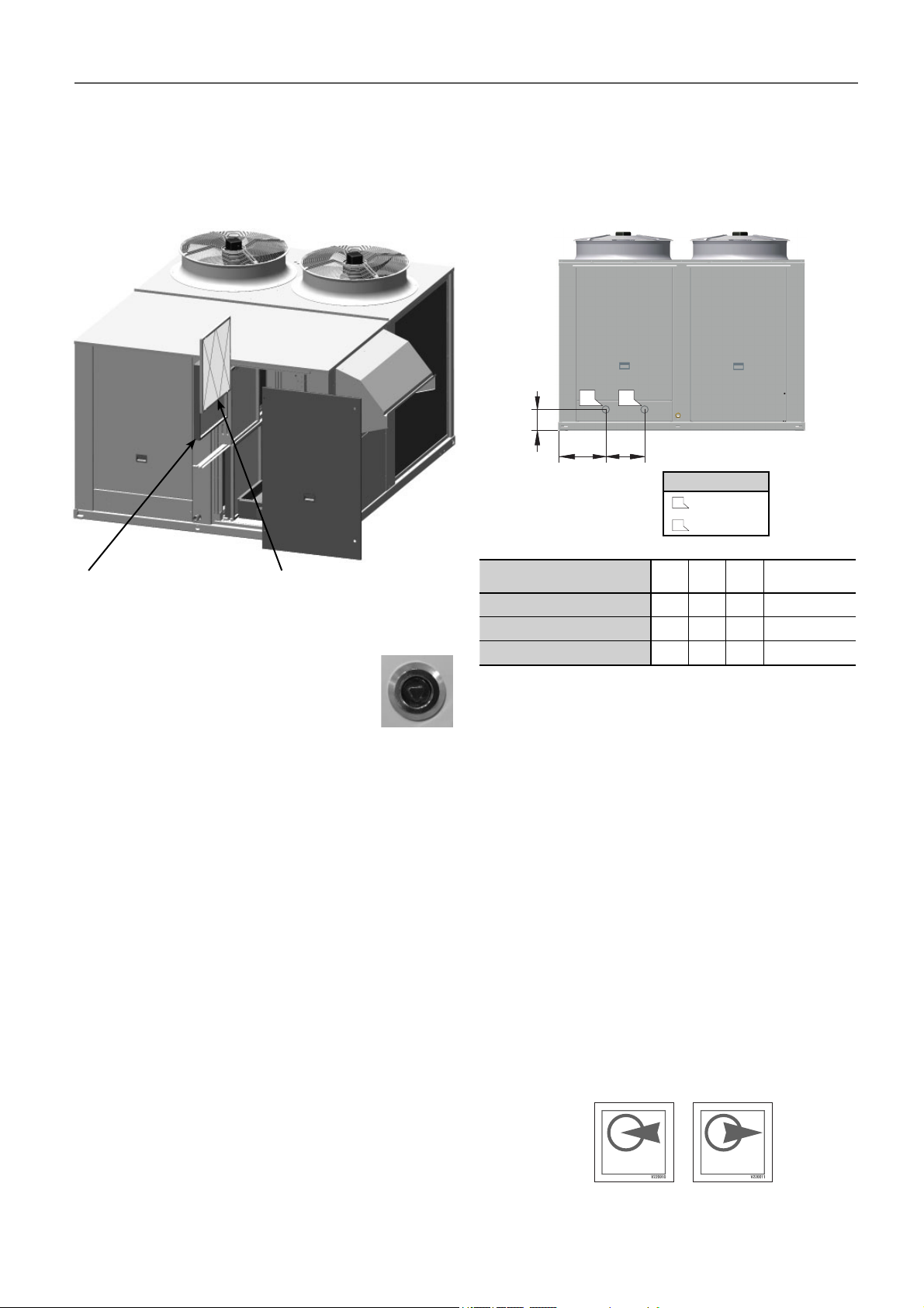
12 - FACTORY OPTIONS AND ACCESSORIES
12.1 Filters
All model types can substitute the fi ltering mesh that the units
include regularly with G4 rating, mounted on the same frames.
Creased opacimetric fi lters classifi ed M6 to F9, as well as double
stage F+F creased opacimetric fi lters, can also be added.
● Assembly inside the unit. The inlet/outlet connections of the
hot water coil are located inside the unit. The connection can
be established via the unit base using fl exible piping or via
the side panel.
In the diagram below the position of the sheet metal precuts
is shown on the side panel.
2
1
C
B
A
LEGEND
1
Water outlet
Water inlet
2
Creased opacimetric fi lters Gravimetric fi lters
Note: The access panel to the fi lters is fi tted with hinges +
quarter-turn latches of stainless steel and triangular insert 8 mm.
● Closing mode:
First rotate 90º (anti-clockwise): closing brings
the latch to the locked position. The door
cannot be opened.
12.2 Hot water coil
● Hot water coil with a three-way valve managed by the
electronic control of the unit. The water coil could be activated
in the following cases:
- As a support in HEATING mode, as the fi rst stage or
subsequently with the input of all the available compressors.
- As support in HEATING mode in accordance with the outlet
temperature.
- During the defrosting operation if selected as support.
- With the unit running or shut down if an anti-freeze alarm
is triggered.
- With the unit stopped when the outdoor temperature drops
below 4ºC. In this case the circulation pump of the water
circuit will be connected.
- As support in COOLING mode in accordance with the return
and the oultlet temperatures.
The pump of the water circuit has to be activated whenever
the 3-way valve is switched on. It is the installer’s responsibility
to connect the pump to the electronic control, except with the
factory-installed GREAT COLD option. Consult the electrical
scheme supplied with the unit.
Note: Refer to the operation mode of the pump with the
GREAT COLD option in the chapter “Safety elements”.
50EN/EH
415 / 420 / 480 / 485 / 540 / 600
650 / 720 / 840 / 960
1100 / 1200
A
(mm)B (mm)C (mm)
302 250 222 2”
302 250 222 2”
302 250 222 2 1/2”
Ø hydraulic
connections: I/O
● Coil fi lling:
- The coil fi lling must be made with the bleeder valve open
until water runs through it, which is when it is time to close it.
- Cut off the water supply and let the bubbles generated go
up to the highest coil point, which is the same as the bleeder
valve, and eliminate by opening the purger.
- Pour more water into the circuit and repeat the previous
steps.
- Activate the water pump (to be foreseen by the installer)
and repeat the previous steps until no air noises are heard
in the piping, which is when the fi lling of the installation will
have been fi nished successfully.
● In case of long unit stops, and forcibly if they happen in the
winter season, the coil must be emptied.
● To prevent the water from freezing, with this option the unit
always has an anti-freezing thermostat. Add glycol to the water
if necessary. With the GREAT COLD option, it is necessary
to consult for glycol percentages higher than 20%.
● The direction of the water fl ow must be correct and so the
following indications must be observed:
HOT WATERCOIL
BATTERIE D’APPOINT
BATERÍADE APOYO
HOT WATERCOIL
BATTERIE D’APPOINT
BATERÍADE APOYO
Note: The hot water coil is not compatible with the stop-drop in
the indoor air coil.
22
Page 23
12 - FACTORY OPTIONS AND ACCESSORIES
12.3 Electrical heaters
● The auxiliary electrical heaters are ready for operation in two
power stages. This heaters are managed by the electronic
control of the unit that can activate them in the following cases:
- As support in HEATING mode, following the input of all the
available compressors.
- In HEATING mode, instead of compressors.
- During the defrosting operation if selected as support.
- As support in COOLING mode in accordance with the return
and outlet temperatures.
● Assembly and connection inside the unit. The electrical heaters
acquired with the unit will be incorporated to it modifying the
electric panel in the factory, so that it is compatible with the
electronic control.
● The electrical heaters requested for units already shipped will
be sent in a kit, and the installer will need to assemble the
necessary elements for the operation of the unit to assemble
and for the compliance with the legal regulations that are
applied to the modifi ed unit in terms of safety.
Note: Consult the available capacities in the technical brochure.
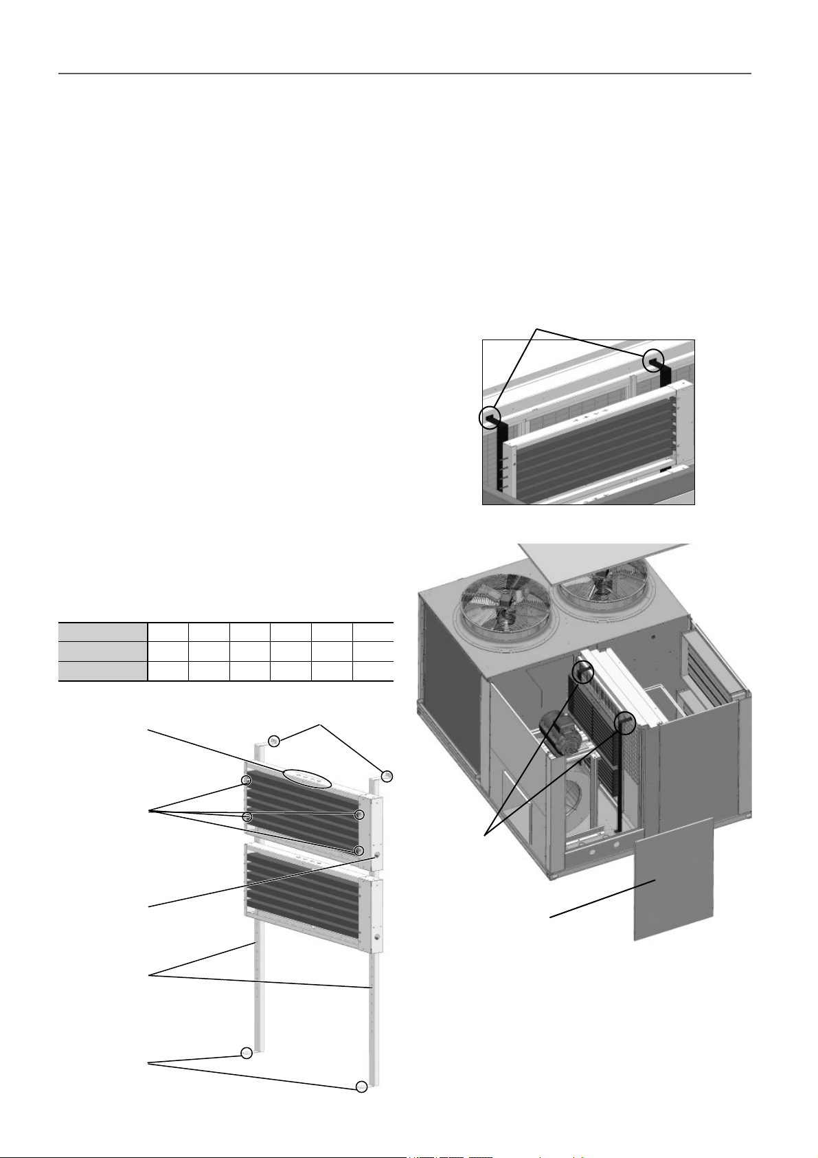
Kit assembly:
To attach these frames to the unit, four supports are provided.
In the case of 2 frames, screw each one of them to 2 supports
with the 4 Allen M4 screws included in the kit.
The height of the frame on the support will depend on the position
of the discharge, since it should never be behind the fan volute.
For example, in the following diagram, the frame location will
be valid for lower and side discharge.
Step 2: attach the supports with the frames linked inside the
unit. To that extent, drills have been made in the unit to which
the supports must be screwed.
Supports attached to the unit
When the frame with the electrical heaters is provided in a kit,
follow the steps below for connecting it:
Step 1: the resistors are sent divided into 1, 2 or 4 frames,
depending on the required power, as shown in the following
table:
Output (kW)
Stages (kW)
No. of frames
Safety thermistor
location
Holes for M4
screws for
attaching to the
unit
Electric power
supply outlet
27 36 45 54 72 90
9 + 18 18 + 18 18 + 27 27 + 27 36 + 36 45 + 45
122244
Holes for screws M4 for
attaching to the unit
Supports
attached to
the unit
Access panel
Supports for
attaching to the
unit
Holes for M4
screws for
attaching to the
unit
Step 3: Take the hoses with the electric power supplies to the
main electric panel of the unit. On the wiring diagram supplied
with the unit an illustration is included with the implantation in
the platen of all the components.
Important: The connection of the necessary elements for the
adequacy to the operation of the unit must be performed by the
installer. The kit is supplied with the required electric material:
thermistors, contactors, hoses, etc.
23
Page 24
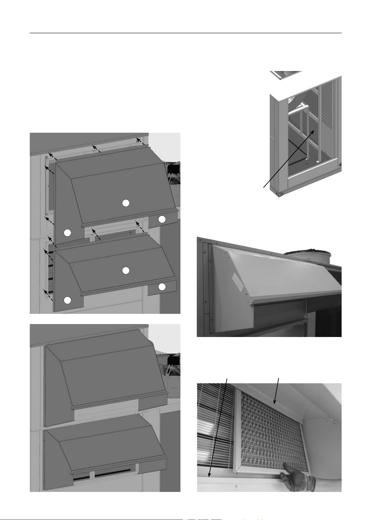
12 - FACTORY OPTIONS AND ACCESSORIES
12.4 Dampers hoods
The fresh air and exhaust air damper hoods (depending on the
assembly chosen) are supplied disassembled. The installer have
to assemble them on site, and then, attach them to the unit.
The three parts that make up the visor (1), (2) and (3) are joined
by self-tapping screws (supplied with the unit).
The upper grip of the hood must be inserted below the panel of
the upper box or the lid in order to prevent water from entering.
Each hood is attached to the unit with Allen M4 screws (supplied
with the unit).
1
3
2
12.5 Stop-drop
The stop-drop can be installed in the indoor air coil and on the
fresh air intake.
● Indoor air coil (available
for models 415 to 960 and
included in models 1100
and 1200): recommended
in cases where a high
moisture content in the air
is foreseen or when the air
fl ow is high.
Note: The stop-drop in
the indoor air coil is not
compatible with the hot
water coil.
This optional is easily
removable from the side of
the unit.
Stop-drop in
the indoor coil
● Fresh air intake: the frames with the stop-drop have to be
placed after the hood (both supplied separated from the unit).
1
3
2
The frames must be inserted behind the top fl ap of the hood,
and then, they must be dropped over the rail.
Top fl apRail
24
Page 25
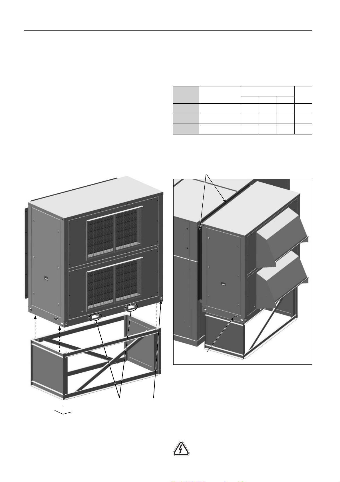
12 - FACTORY OPTIONS AND ACCESSORIES
12.6 Rotary heat exchanger
The rotary heat exchanger, available for models 415 to 960,
consists of a module attached to one side of the 50EN/EH unit
(MWC1 assembly).
● This module incorporates washable fi lters in the fresh air
intake and in the output of the extraction air. Optionally, they
can be replaced by G4 or G4 with low pressure drop.
● The MWC1 assembly can be supplied, in option, with a speed
drive for the wheel which avoids the risk of icing on the wheel
during the defrost operation.
Handling and transport
● Both the recovery module and its curb are supplied separately
from the machine. The curb must be fi xed to the module using
4 screws M8, in the points indicated in the following image.
● The module can be handled with a forklift truck. For this
purpose, the module base incorporates 2 guide rails in which
the truck’s fork will be inserted to prevent any sliding.
Weight and centre of gravity of module + curb:
The set of module + curb must be lifted and fi xed with care and
without inclination (maximum inclination 15º). Please consult
the coordinates of the centre of gravity and the weight in the
attached table.
50EN/EH
415 / 480
420 / 485
540 / 600
650 / 720
840 / 960
Wheel
confi guration
1500, Aluminium
Cross section: 1,7mm
1800, Aluminium
Cross section: 1,7mm
2000, Aluminium
Cross section: 1,7mm
Centre of gravity of
module + curb (mm)
XYZ
987 418 1594 751
1297 393 1163 901
1296 396 1438 945
Weight
Attachment of the recovery module to the machine:
The attachment is made using the profi les that incorporates the
module at the two sides and at the top. The module is secured
using M6 Allen screws (supplied with the unit).
Profi les for the attachment of the module
Z
Y
X
Guide rails
for forks
Lifting holes
for slings
● For the transport and lifting to the roof using a crane cloth
slings with rings will be used, with the appropriate resistance,
separated by a strut to avoid damaging the casing.
These slings will be hooked onto the four lifting holes
availables on the base of the module.
Condensate
drain 1”M
The installer must also place the damper hoods. To do this,
follow the steps described in paragraph 12.4.
Note: the access to the inside of the module can be found in the
chapter “Maintenance”.
Electrical connection to be made by the costumer:
For the electrical connection of the module, the cable located in
the interior of the 50EN/EH unit must be connected in the box
located inside the module.
Note: see the wiring diagram included with the unit for a more
detailed information about the wiring.
It is mandatory to make all electrical connections
before energizing the unit.
25
Page 26
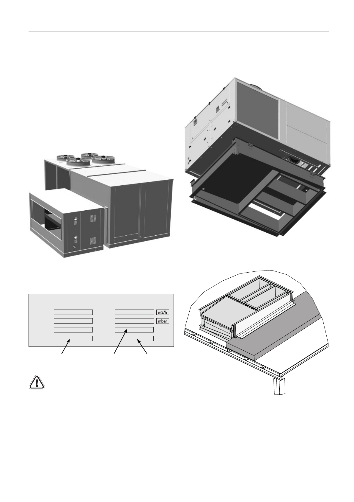
12 - FACTORY OPTIONS AND ACCESSORIES
12.7 Gas burner
● Natural gas or propane gas burner with proportional actuator
0-10V designed in accordance with the standards in force in
compliance with the Gas Directive 90/396 EEC.
EC certifi cation: 0694CP1457.
● The electronic control of the 50EN/EH unit will only be
managed by the burner connection as support for the heating
depending on ambient conditions. The control will also receive
from the burner a safety signal in the event of failure.
● The burner module is fi tted with a controller installed inside
as standard. This controller is used to manage, confi gure and
diagnose all the operating parameters and safeties in the
burner.
12.8 Pre-assembly roofcurb
The 50EN/EH unit can be attached to a standardised pre-
assembly roofcurb with adjustable height, built in galvanised
steel panelling with polyester paint and thermal insulation.
The burner module includes a name plate featuring the main
gas characteristics as well as the 50EN/EH unit serial number
on which it is to be mounted.
GAS INFORMATION
COUNTRY
GAS
CATEGORY
PIN
50EN/EH unit with
burner CE certifi cate No.
CONSUMPT.
PRESSURE
TYPE
WO
Burner
model
m3/h
mbar
50EN/EH unit
identifi cation No.
The serial number must be used in all communication
regarding the unit.
Important: All the necessary information about the
installation, commissioning and maintenance of the burner
module is available in the specifi c instruction brochure on
gas burner No. 09.100, as well as in the manufacturer’s
(APENGROUP) installation and maintenance brochure
for the burners in the PCH series (both supplied with the
burner).
The following image shows a detail of the installation of the
roofcurb on a roof. The levelling system uses angle pieces that
allow adjustments in the X and Y axes.
The roofcurb is supplied thermally isolated, the installer must
only do a sealing upsweep around the roofcurb to ensure that
water does not penetrate the roof.
Important: All the necessary information about the
installation of the roofcurb is available in the specifi c
instruction brochure on roofcurb No. 12.62 (supplied with
the roofcurb).
26
Page 27
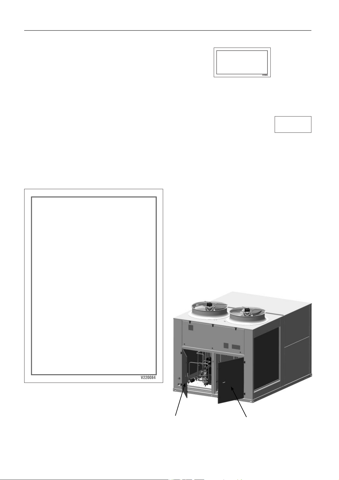
13 - COMMISSIONING
13.1 Checks prior to commissioning
● It is advisable to make a complete sketch of the installation
including the location of the unit and all the components used.
This will be very helpful for maintenance and repairs to the
installation.
● The following must be verifi ed:
- That the electrical power supply remains constant and that
it corresponds to that featured on the unit data plate.
- That the electric installation has been carried out according
to the electric wiring diagram provided with the unit (consult
the chapter on “Electrical connection”).
- The correct connection of the sensors supplied with the unit
(consult the chapter on “Electrical connection”).
- That they are no cables close to heat sources.
● Once the above verifi cations have been carried out, the control
circuit is supplied with voltage by the automatic control switch.
Attention: the compressor crankcase heater must be put
under voltage for 24 hours before starting the compressor.
WICHTIG: WIEDERBEHEIZUNG DER
OLWANNE
BEIDER ERSTEN INBETRIEBSETRUNZ ORDER NACH EINER
LANGEN STROMUNTER-BRECHUNG BRINGEN SIE DIE
MASCHINE UNTER SPANNUNG 24 STRUNDERLANG
BEVOR SIE DEN(DIE) KOMPRESSOR(EN) EINSCHALTEN
KOENNEN.
IMPORTANT: CRANKCASE HEATING
FOR THE FIRSTSTART OR AFTER ALONG TIME OUT OF
VOLTAGE PUT THE MACHINE ON LIVE 24 HOURS BEFORE
TO ALLOW THE COMPRESSOR(S) STARTING
IMPORTANT: SURCHAUFFE CARTER D’HUILE
AU PREMIER DÉMARRAGE OU APRÈS UNE ABSCENCE
DE COURANT PROLONGÉE, METTRE LA MACHINE SOUS
TENSION 24 HEURES AVANT D’AUTORISER LE
DÉMARRAGE DU(DES) COMPRESSEUR(S).
SCROLL COMPRESSOR.
CHECK SENSE OF ROTATION
COMPRESSEUR SCROLL.
VÉRIFIER LE SENS DE ROTATION
COMPRESOR SCROLL.
COMPROBAR SENTIDO DE GIRO
● Check the unit operation and verify the safety devices.
Control of the refrigerant charge
● Each unit is shipped with an exact charge
of refrigerant for proper operation.
● To make sure that the unit is fi lled with the correct charge of
refrigerant, check the values of overheating and subcooling,
circuit by circuit, with the system running at full capacity.
If the refrigerant charge is lower than required, the suction
pressure will drop and overheating on the compressor inlets
will be high. This can cause an interruption in operation due
to activation of the refrigerant charge safety device.
To adjust the refrigerant charge, a schrader type valve is built
into the unit on the liquid line for each circuit. This changing
valve is located inside the compressor box.
● Verify the absence of any leaks of the refrigerant. In case of
a leak:
- Completely drain the refrigerant charge using a specifi c
recovery machine for R-410A and repair the leak.
- Next, reload the refrigerant into the unit according to charge
data provided in a table of the chapter on “Maintenance”
and in the unit’s data plate.
- Add the refrigerant via the charging valve using the
appropriate equipment and tools, with the compressors
stopped, monitoring the pressures to control any anomaly.
R 410A
IMPORTANTE: RISCALDARE IL CARTER
DELL’OLIO
AL PRIMO AVVIAMENTO U DOPO UNA INTERRUZIONE
PROLUNGATA DELLA ALIMENTAZIONE ELETTRICA,
LASCIARE LA MACCINA SOTTO TENSIONE PER 24 ORE
PRIMA DI AUTORIZZARE L’AVVIAMENTO DEL(DEI)
COMPRESSORE(I).
IMPORTANTE: RECALENTAMIENTO DE
ACEITE DEL CÁRTER
ANTES DEL PRIMER ARRANQUE O DESPUÉS DE UNA
AUSENCIA DE CORRIENTE POR UN LARGO PERIODO DE
TIEMPO, CONVIENE QUE LA UNIDAD ESTÉ CONECTADA
UN MÍNIMO DE 24 HORAS.
Important: As a safety feature to ensure heating of the
crankcase heater, if there is a power cut lasting over 2 hours,
the compressors will be locked. The unit must be powered for
8 hours to unlock them. The pGD1 terminal unit display will
shows the time remaining until they can be unlocked.
● All the units are equipped with scroll type compressors and a
phase control relay. Verify that they rotate in the correct sense
and, if not, reverse the power wires.
Access to the compressors
enclosure of circuit 1 and
recovery circuit (optional)
Note: in units with 4 circuits:
access to the circutis 1 and 2
Models 415 and 480
Access to the compressors
enclosure of circuit 2
Note: in units with 4 circuits:
access to the circutis 3 and 4
27
Page 28
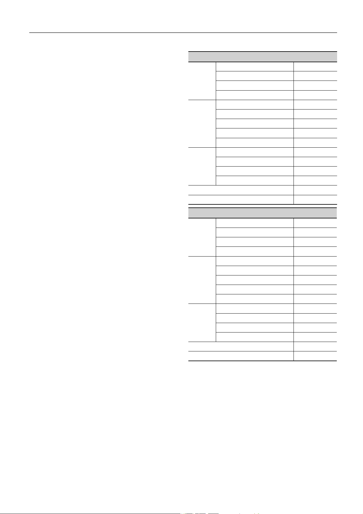
13 - COMMISSIONING
13.2 Possible problems at commissioning
All indications given in this manual must be respected and
complied with to guarantee a correct operation of the units.
Next, several possible operation problems are stated which
could happen if the conditions of the commissioning are not
appropriate.
● Air fl ow lack: very high diff erences between inlet and outlet
temperatures, originated by a high pressure drop in the ducts,
or by other causes that impede the correct circulation.
● Air recirculation in the unit, originated by some obstacle in the
air aspiration or outlet.
● Noise problems because of excessive air fl ow in the grille.
● Water overfl owing to the pan problems, originated by an
excessive fl ow, an incorrect siphon installation or because a
defective unit level.
● Refrigerant circuit humidity problem, because of an incorrect
vacuum realization.
13.3 Operational checks
Check the unit operation by verifying the electronic control and
the safety devices.
It is also recommendable to create a report, taking note of the
date, which includes the following information:
● the nominal voltage,
● current absorbed by the compressors, fans and other electrical
components,
● signifi cant temperatures in the cooling circuit (see attached
table),
● other aspects considered interesting such as alarms detected
by the electronic control of the unit.
The recording of these parameters whilst the unit is running
allows controlling the installation performance and it is the
best possible way to avoid breakdowns since the analysis of
these data makes early detection of anomalies possible or the
provision of the necessary means available to ensure that they
do not take place.
Operating readings
Cooling MODE
Suction pressure bar
Compressor
Air
condenser
Air
evaporator
Subcooling (2) - (3) ºC
Overheating (4) - (1) ºC
Heating MODE
Compressor
Air
evaporator
Air
condenser
Subcooling (2) - (3) ºC
Overheating (4) - (1) ºC
Suction temperature (1) ºC
Condensation pressure bar
Condensation temperature (2) ºC
Gas inlet temperature ºC
Liquid outlet temperature (3) ºC
Air inlet temperature ºC
Outdoor temperature ºC
Air outlet temperature ºC
Air inlet temperature ºC
Air outlet temperature ºC
Liquid inlet temperature ºC
Evaporation outlet temperature (4) ºC
Suction pressure bar
Suction temperature (1) ºC
Condensation pressure bar
Condensation temperature (2) ºC
Liquid inlet temperature ºC
Gas outlet temperature (4) ºC
Air inlet temperature ºC
Outdoor temperature ºC
Air outlet temperature ºC
Air inlet temperature ºC
Air outlet temperature ºC
Gas inlet temperature ºC
Liquid outlet temperature (3) ºC
28
Page 29
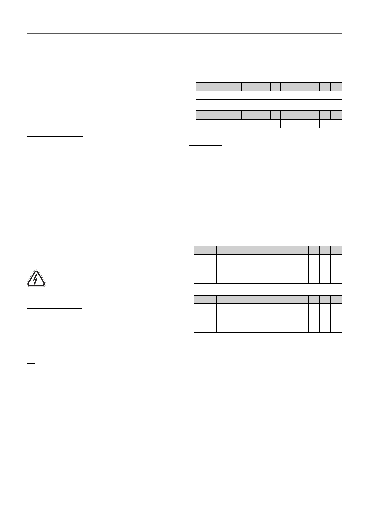
14 - MAINTENANCE
The minimal maintenance operations and their periodicity
will be made in accordance with national regulations.
All work on the unit’s electrical or refrigerant systems must
be carried out by a qualifi ed authorised technician. See the
standard EN 378-4.
It is advisable to sign a maintenance contract with the installer
or an approved maintenance company.
14.1 General recommendations
Safety instructions
● Technicians working on the unit must wear the necessary
safety gear (e.g. gloves, eye protection, insulating clothing,
safety shoes).
● Similarly, it is recommended that personnel working close
to sources of high noise emission wear ear defenders. The
ear defenders should in no way impede the wearing of other
protective equipment.
● The surfaces of the compressor and pipes may reach
temperatures of over 100°C and cause burns if touched.
Likewise, the surfaces of the compressor may in some cases
drop to freezing temperatures which can cause frostbite. It is
therefore important to take special care when carrying out
maintenance work.
● Do not climb on the machine; use a platform to work at the
necessary height.
● Do not climb on the copper refrigerant pipes.
Caution: Do not work on any electrical components
without fi rst turning off the main door switch in the
electric panel.
Preliminary advise
● Keep the unit clean.
● To avoid accidents and ensure proper ventilation of the coil,
keep the unit and the space around it clean and clear of clutter.
● Check the fouling level of the coil.
Oil
Oils for refrigeration units do not pose any health risks if they
are used in compliance with the precautions for use:
● Avoid unnecessary handling of components lubricated with
oil. Use protective creams.
● Oils are fl ammable and must be stored and handled with care.
Disposable rags or cloths used in cleaning must be kept away
from open fl ames and disposed of in the appropriate manner.
● Containers must be stored with their caps on. Avoid using oil
from an opened container stored under incorrect conditions.
● Check the oil level and aspect. In case of a colour change,
check the oil quality using a contamination test.
● In the case of the presence of acid, water or metallic particles,
replace the aff ected circuit oil, as well as the fi lter dryer.
● If all the oil must be emptied, replace it imperatively with new
oil of the same grade as the original oil which has been stored
in a hermetically sealed container until its time of use.
The oil type recommended for these units is:
Copeland 3MAF 32cST, Danfoss POE 160SZ, ICI Emkarate
RL 32CF, Mobil EAL Artic 22CC.
The following table indicates the required volume:
Main circuits:
50EN/EH 415 420 480 485 540 600 650 720 840 960 11001200
Volume (l)
Recovery circuit (optional):
50EN/EH 415 420 480 485 540 600 650 720 840 960 11001200
Volume (l)
4 x 3,3 4 x 6,2
3,0 3,3 4 6,2 6,2
Refrigerant
Only qualifi ed personnel must perform a periodic leak testing, in
accordance with the regulation (EC) No. 517/2014.
● The frequency of checks is no longer related to the refrigerant
charge but to its global warming potential:
Charge kg x GWP = t CO2e
Carbon dioxide equivalency (t CO2e) is a quantity that
describes, for a given mixture and amount of greenhouse
gas, the amount in tonnes of CO2 that would have the same
global warming potential (GWP).
The number of tonnes of CO2 equivalent (t CO2e) can be
consulted in the following table:
Main circuits:
50EN/EH 415 420 480 485 540 600 650 720 840 960 1100 1200
2 x
2 x
2 x
2 x
2 x
2 x
2 x
2 x
4 x
4 x
4 x
Charge
(kg)
Environ.
impact
(t CO2e)
Recovery circuit (optional):
50EN/EH 415 420 480 485 540 600 650 720 840 960 1100 1200
Charge
(kg)
Environ.
impact
(t CO2e)
17,0
17,0
14,5
17,0
21,0
21,5
26,5
26,0
14,5
14,5
71,0 71,0 60,6 71,0 87,7 89,8 110,7 108,6 121,1 121,1 119,4 129,5
8,0 8,5 8,2 9,0 10,0 10,0 10,0 10,0 9,5 9,5 10,5 10,5
16,7 17,7 17,1 18,8 20,9 20,9 20,9 20,9 19,8 19,8 21,9 21,9
● Operators shall ensure that the unit is checked for leaks ad
minima according to the following frequency:
• t CO2e < 5 ......... not subjected
• t CO2e 5 to 50 ... every year
• t CO2e 50 to 500 every 6 months
• t CO2e > 500 ...... every 3 months
● Where a leakage detection system has been installed the
frequency of checks is halved.
Note: These machines use R410A. It is essential that technicians
use equipment which is compatible with R410A with a working
pressure which is approximately 1.5 times higher than that of
units using R407C.
● Always remember that refrigeration systems contain
pressurised liquids and vapours. All necessary provisions
must be made when the system is partially opened: ensure
the part of the circuit concerned is not pressurised.
● Partial opening of the primary refrigerating circuit will
cause a certain quantity of refrigerant to be released into
the atmosphere. It is essential to keep the amount of lost
refrigerant as low as possible by pumping the charge and
isolating it in another part of the system.
14,3
4 x
15,5
29
Page 30
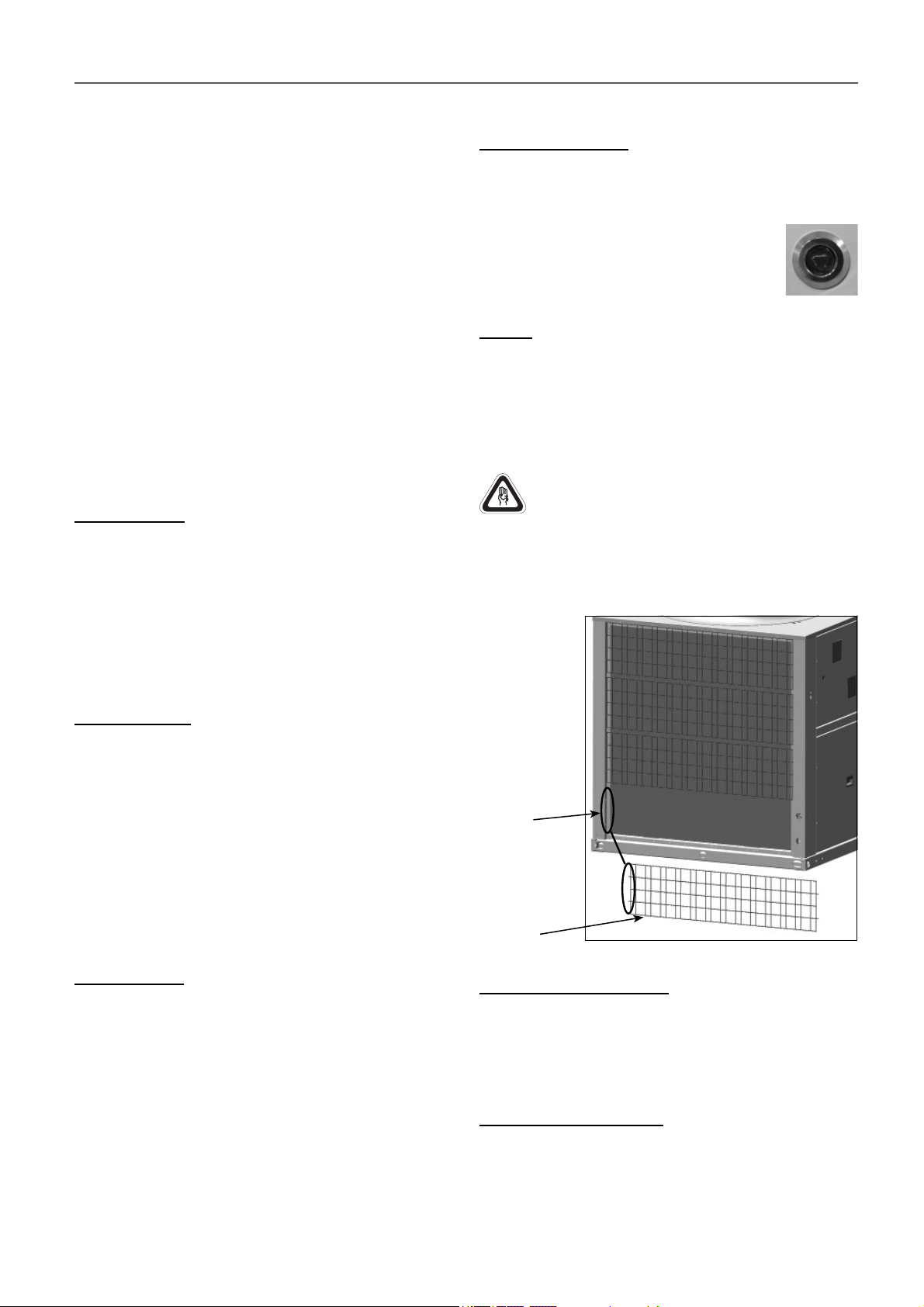
14 - MAINTENANCE
● The refrigerant and lubricating oil, and the low-temperature
liquid refrigerant in particular, may cause infl ammatory lesions
similar to burns if they come into contact with the skin or eyes.
Always wear protective eyewear, gloves and other protective
equipment when opening pipes or tanks liable to have liquids
in them.
● Store unused refrigerant in the appropriate containers and
limit the amounts stored in mechanical rooms.
● Cylinders and tanks of refrigerant must be handled with care
and signs warning users of the related poisoning, fi re and
explosion hazards must be clearly visible.
Refrigerant that reaches the end of its life must be collected
and recycled in accordance with applicable regulations.
14.2 Servicing
It’s recommended to note down the operating readings and
perform the following checks at least twice a year and mandatory
after each time a unit is started for seasonal use.
Weekly checks
With the unit running at full capacity, check the following values:
● LP compressor suction pressure and HP compressor
discharge pressure.
● The oil level and its appearance. If the colour changes, check
the quality.
● Also check whether the safety devices operate correctly.
● Check the entire system for traces of water or oil under or
around the unit and for any unusual noises.
14.3 access to the main components
Quarter-turn latches
The access panels to fi lters, supply fans, compressors and
electric panel are fi tted with hinges + quarter-turn latches. These
latches of stainless steel have triangular insert 8 mm.
● Closing mode:
First rotate 90º (anti-clockwise): closing brings
the latch to the locked position. The door
cannot be opened.
Air coil
● Check that the coil is free from dust and grease.
● Cleaning the accumulated dust on the coil can be performed
using a soft-bristled brush or a vacuum cleaner perpendicular
to the fi ns or with a low-pressure water cleaner. Grease can
be removed with water with degreaser. Do not put stress on
the fi ns as they could deform.
Use safety gloves for this task. Take care with the sharp
parts of the coil.
V-220005
Outdoor coil protective grille (optional)
All the models can include a protection grille for this coil. This
grille is fi xed by modules in the holes made for this goal in
the unit’s support.
Monthly checks
● Check all the values listed in the table “Operating readings“
on chapter 13.
● Check for corrosion on all metal surfaces (chassis, casing,
exchangers, electric panel, etc.).
● Make sure that the insulating foam is neither detached nor
torn.
● Check the coolants for any impurities which could cause
wearor corrosion in the exchanger.
● Check the circuits for leaks.
● Check whether the safety devices and the expansion valve(s)
operate correctly.
Annual checks
● Carry out the same inspections as during the monthly checks.
● Carry out an oil contamination test (every year or every 5000
hours). If acid, water or metal particles are found, replace
the oil in the circuit concerned and the dryer. Follow the
recommendations of paragraph 14.1.
● Check the electrical connections to ensure they are tight and
in good condition.
● Check the condition of the contacts and the current at full load
on all three phases.
● Check the electrical box for water seepage.
N.b.: The intervals for cleaning are given as a guide and should
be adapted to each unit.
Holes
Grille
module
Condensate drainage pan
● Check that the condensate pan is suffi ciently clean.
● Check that the drain is not clogged.
● Cleaning of the pan can be done with water and non-abrasive
detergent.
Centrifugal fan (optional)
● Verify that the turbine and the motor remain clean.
● Foresee having a spare belt set for the fans.
● The motors and the fans have bearings that have been
lubricated and sealed and, thus, do not need further lubrication
(except in the case of fans with a reinforced shaft).
30
Page 31
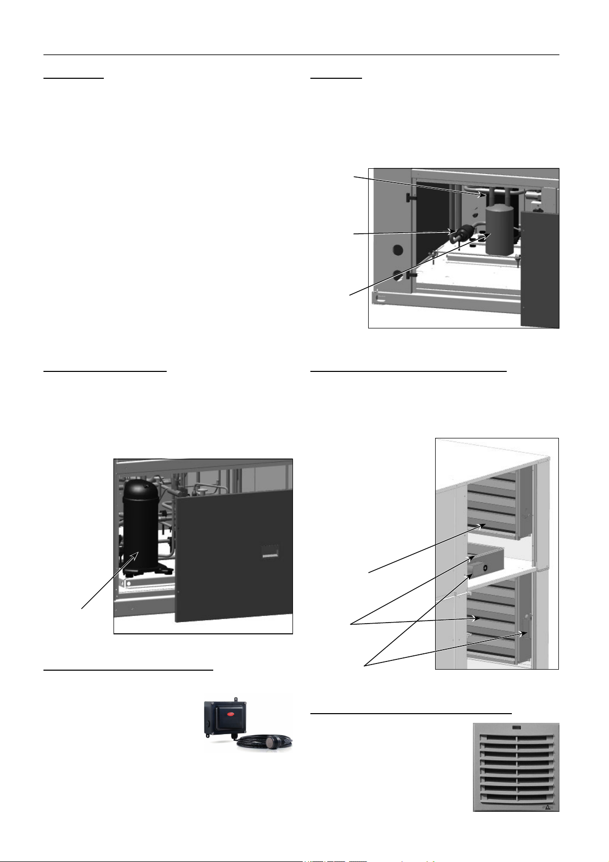
14 - MAINTENANCE
Compressor
In the case of compressor replacement:
● Disconnect the unit from power supply.
● Completely empty the refrigerant charge using a specifi c
recovery unit for R-410A
● Disconnect electrically the compressor.
● Carefully unsolder the suction and discharge piping.
● The compressor is fi xed onto the platform with 4 screws.
● Unscrew the fi xings.
● Place the new compressor and check that it has a suffi cient
oil charge.
Warning: when tightening the compressor screws, please
consult the maximum torque that can be applied.
If a torque wrench is not available,tighten them until they are
snug then tighten a further ¾ turn.
● Solder the suction and discharge piping.
● Connect the compressor in accordance with the wiring
diagram.
● Make vacuum and next, reload the gas into the unit according
to charge data provided in the table of paragraph 14.1
“General recommendations” and in the unit’s data plate.
Active recovery (optional)
Dryer fi lter
● The fi lter function is the preserve the cooling circuit clean and
without humidity, neutralizing the acids that can be found in
the cooling circuit.
● Measure the diff erence in the temperature of the pipes at the
dryer inlet and outlet.
● If necessary, replace.
Compressor
Filter drier
Particle
separator
Mixing boxes and free-cooling (optional)
● A cooling recovery circuit is optionally available for these units
(MRC0 and MRC1 assemblies). It is a complete circuit with
independent electronic control.
● The same recommendations for the maintenance of the
components of the main circuits must be followed for the
components of this circuit.
Recovery
circuit
compressor
Refrigerant leak detector (optional)
Maintenance:
● Annual testing: it is necessary
to carry out testing every year to
comply with the EN378 and F-GAS
regulations.
● Every 3 years: a taring test is
recommended.
● Every 5/6 years: it is recommended that the gas detection
element be replaced and calibration performed.
Note: Check the documentation attached to the leak detector
for taring and calibration testing.
In units with mixing box assemblies with motorised dampers it
is advisable to check the condition of the servomotors.
● Assemblies with 2 dampers-> 1 servo
● Assemblies with 3 dampers -> 2 servos
Note: The available
assemblies can be
consulted in chapter 3.
Damper locked
with the mixing
damper
Motorised
dampers
Servomotors
Air fi lters in the grids of the electric panel
● The appearance of the fi lters located
inside of the grids must be examined
periodically, because the clogged
fi lters impede good ventilation.
● Cleaning can be done with a
household vacuum cleaner. Replace
them regularly.
115 x 115 mm G2 fi lters.
31
Page 32
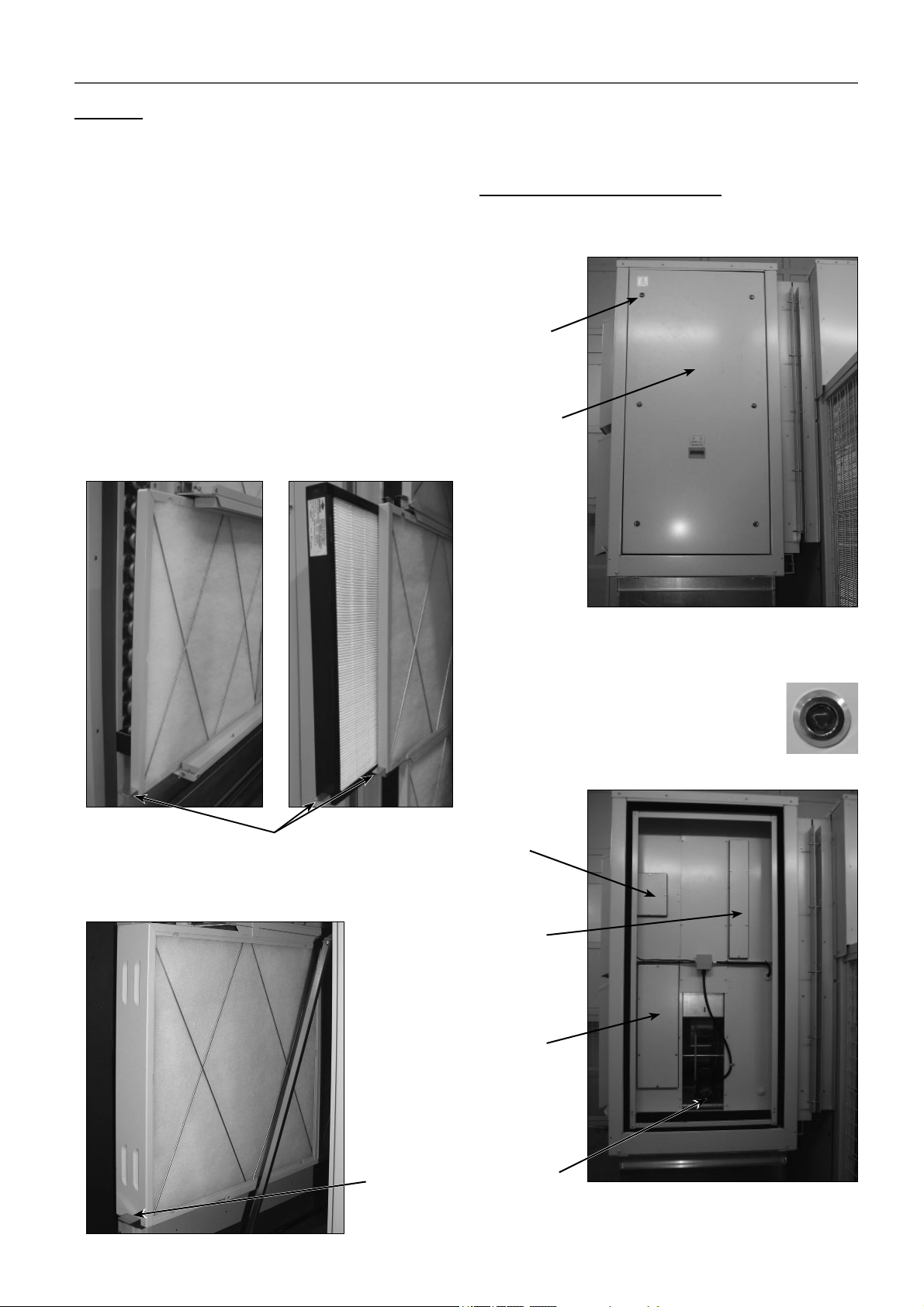
14 - MAINTENANCE
Air fi lters
● Depending on the installation conditions, the fi lter aspect must
be examined to defi ne the cleaning or replacing periodicity.
Spare parts should be planned for.
The pressure drop data are given on the technical catalogue.
Cleaning the fi lters is very important to maintain the required
available pressure of the unit.
On units with a clogged fi lter diff erential pressure switch, an
alarm is triggered on the electronic control when the factory-set
clogging threshold is exceeded depending on the combination
of fi lters selected.
● Gravimetric fi lters (G). Cleaning can be done with a household
vacuum cleaner. Replace them regularly.
● Creased opacimetric fi lters (F). It is necessary to replace them.
Filter removal:
● Filters G or G+F: the frames with each type of filters,
gravimetrics and opacimetric (if the unit has includes the
latter), are assembled over sheet steel profi les. By dragging
a tab, they slide along the corresponding rail.
Note: the access panel to the fi lters is fi tted with hinges + quarterturn latches of stainless steel and 8 mm triangular insert.
Rotary heat exchanger (optional)
By the right panel (viewed from the front), it is possible to access
inside of the recovery module to carry out the maintenance work.
Quarter-turn
latches
Access panel
to the recovery
module
Tabs in displacement
● Filters F+F: the frames with the set of filters F+F are
assembled over a sheet steel profi le. By dragging a tab, they
slide along the rail.
The removal side panels of the module incorporate stainless
steel quarter-turn latches with 8 mm triangular inserts.
● Closing mode:
First rotate 90º (anti-clockwise): closing brings
the latch to the locked position. The door
cannot be opened.
Acces to the
servomotor of
the extraction
damper
Access to
gravimetric
fi lters in the
extraction air
Access to
gravimetric
fi lters in the
fresh air and
to the damper
servomotor
32
Tabs in
displacement
Wheel motor
The procedure for extraction and cleaning of fi lters is equal to
that described in the previous section.
Page 33

15 - CONTROL AND ANALYSIS OF BREAKDOWNS
Symptom Cause Solution
Evaporation pressure very high in relation with
the air inlet
Very low condensation pressure a) Gas lack
Condensation pressure very high in relation to
the air outlet, high pressostat cutoff
Evaporation pressure too low (low pressure
safety cut-off )
Compressor does not start, does not make
noise (humming)
Compressor does not start, motor sounds
intermittently
Repeated compressor starts and stops a) Because of high pressure
The compressor makes a noise a) Loose attachment
Noisy operation a) Unit installed without antivibration protection a) Place base over shock absorbers
Cycle reversing is not carried out:
- No defrosting
- Does not change winter - summer cycles
Alarm or reading error in the humidity probe
(with enthalpic control)
a) Charge excess
b) High air temperature
c) Compressor suction not air tight
d) Cycle reversing valve in middle position
b) Compressor suction not air tight
c) Cycle reversing valve in middle position
d) Liquid circuit plugging
a) Insuffi cient air fl ow
b) Air inlet temperature very high
c) Dirty condenser (does not exchange)
d) Much refrigerant charge (fl ooded condenser)
e) The condenser fan is broken down
f) Air in the cooling circuit
a) Low fl ow in evaporator. Air recirculation
b) Frozen evaporator
c) Liquid line as diff erent temperatures at fi lter
inlet and outlet
d) Gas lack
e) Very low condensation pressure
f) Evaporator fan broken down
a) No power
b) The contacts of a control element are open
c) Timing of anti cycle short does not allow the
starting
d) Open contact
e) Contactor coil burnt
f) Indoor klixon open
a) Electrical power supply very low
b) Power cable disconnected
b) Control diff erential too short (short cycle)
c) Insuffi cient gas, cut-off because of low
pressure
d) Dirty or frosted evaporator
e) The evaporator fan does not work, cuts off the
low pressostat
f) Expansion valve damaged or clogged by
impurities (cuts off the low pressure safety)
g) Dehydrating fi lter clogged (cuts off the low
pressure safety)
b) Oil lack
c) Compressor noise
a) Electrical fault
b) Inversion valve coil defective
c) Defrost method not working
d) Cycle reversing valve in middle position
e) Control fault
a) Dirt in the humidity sensor a) Disassembly the probe encapsule.
a) Collect refrigerant
b) Verify overheating
c) Verify compressor state and replace
d) Check that the valve is not clogged. Replace
if necessary
a) Search for leaks, complete charge
b) Verify compressor state and replace
c) Check that the valve is not clogged. Replace
if necessary
d) Verify the dehydrating fi lter and expansion
valve
a) Verify the air circuits (fl ow, fi lter cleanliness...)
b) Verify the control thermostat readjustment
c) Clean it
d) Collect refrigerant
e) Repair
f) Make vacuum and charge
a) Verify the air circuits (fl ow, fi lter cleanliness...)
b) Verify defrost
c) Replace fi lter
d) Search for leaks, complete charge
e) Temperature of air or water in condenser very
low (air or water fl ow very high), adjust fl ow
f) Repair
a) Check diff erential, fuses
b) Verify the safety chain of the electronic control
c) Verify electronic control
d) Replace
e) Replace
f) Wait for reactivation, verify current absorbed
a) Control line voltage and locate voltage drop
b) Verify connections
a) Verify charge
b) Increase diff erential
c) Search for leak, reload unit
d) Clean, verify evaporator air circuit
e) Replace or repair
f) Replace, as well as fi lter
g) Replace
a) Fix
b) Add oil to recommended level
c) Replace
a) Locate and repair
b) Replace
c) Verify parameters
d) Tap with running compressor. Replace if
necessary
e) Locate and repair
Proceed to clean the sensor with some soft
cotton element and non-abrasive fl uid, without
pressing it.
Reassemble the casing, checking that the
cable is in contact externally with the metallic
mesh.
33
Page 34

16 - FINAL SHUTDOWN
16.1 Shutting down
Separate the units from their energy sources, allow them to cool
then drain them completely.
16.2 Recommendations for disassembly
Use the original lifting equipment.
Sort the components according to their material for recycling or
disposal, in accordance with regulations in force.
Check whether any part of the unit can be recycled for another
purpose
16.3 Fluids to be recovered for treatment
● Refrigerant
● Energy transfer fl uid: depending on the installation, water,
glycol/water mix.
● Compressor oil
16.4 Materials to be recovered for recycling
● Steel
● Copper
● Aluminium
● Plastics
● Polyurethane foam (insulation)
16.5 Waste electrical and electronic equipment
(WEEE)
At the end of its life, this equipment must be disassembled and
contaminated fl uids removed by professionals and processed
via approved channels for electrical and electronic equipment
(WEEE).
Important: In order to recycle these units follow the
stipulations of Directive 2012/19/EU on Waste electrical
and electronic equipment (WEEE).
34
Page 35

Page 36

CARRIER participates in the ECP programme for RT
Check ongoing validity of certifi cate:
www.eurovent-certifi cation.com
Order No.: 10049, 12.2018. Supersedes order No.: 10.2016 Manufactured for CARRIER in Spain.
Manufacturer reserves the right to change any product specifi cations without notice. Printed in the European Union.
 Loading...