

Carrier 50DPE014 User Manual
50DPE014
50DP016,020
HEATING & COOLING
Single-Package Cooling Units
Installation, Start-Up and Service Instructions
CONTENTS
Page
SAFETY CONSIDERATIONS
INSTALLATION
Step 1 — Provide Unit Support
..................................................
..............................
..........................
1
1-10
1
• ROOF CURB
• ALTERNATE UNIT SUPPORT
Step 2 — Rig and Place Unit
...............................
1
• POSITIONING
• ROOF MOUNT
Step 3 — Field Fabricate Ductwork
Step 4 — Make Unit Duct Connections
Step 5 — Trap Condensate Drain
Step 6 — Make Electrical Connections
...................
.............
.......................
..............
6
6
6
7
• FIELD POWER SUPPLY
• FIELD CONTROL WIRING
Step 7 — Make Outdoor Air Inlet
Adjustments
......................................................
7
• MANUAL OUTDOOR AIR DAMPER
• OPTIONAL ECONOMIZER
Step 8 — Install Outdoor Air Hood.................. 10
START-UP..........................................................10-13
SERVICE.............................................................14-16
SAFETY CONSIDERATIONS
Installation and servicing of air conditioning equip
ment can be hazardous due to system pressure and elec
trical components. Only trained and qualified service
personnel should install, repair or service air conditioning
equipment.
Untrained personnel can perform basic maintenance
functions of cleaning coils and filters and replacing
filters. All other operations should be performed by
trained service personnel. When working on air condi
tioning equipment, observe precautions in the literature,
tags and labels attached to the unit and other safety pre
cautions that may apply.
Follow all safety codes. Wear safety glasses and work
gloves. Use quenching cloth for unbrazing operations.
Have fire extinguishers available for all brazing
operations.
A WARNING
Before performing service or maintenance operations
on unit, turn off main power switch to unit. Electrical
shock could cause personal injury.
INSTALLATION
Step 1 — Provide Unit Support
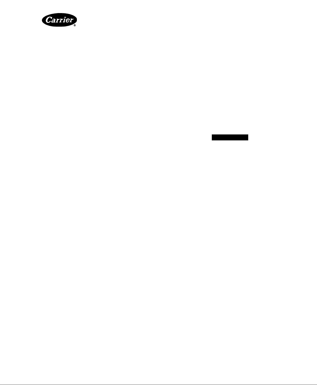
ROOF CURB — Assemble and install accessory roof
curb in accordance with instructions shipped with this
accessory. Accessory roof curb and information required
to field fabricate a roof curb are shown in Fig. 1 and 2.
Install insulation, cant strips, roofing and flashing as
shown. Ductwork can be installed to roof curb before unit.
is set in place. Curb should be level. Unit leveling toler
ance is ± 1/16 in. per linear ft in any direction. This is
necessary to permit unit drain to function properly. Refer
to Accessory Roof Curb Installation Instructions for
additional information as required.
ALTERNATE UNIT SUPPORT — When the curb
cannot be used, support unit with sleepers using unit curb
support area. If sleepers cannot be used, support long
sides of unit with a minimum of 3 equally spaced 4-in. x
4-in. pads on each side.
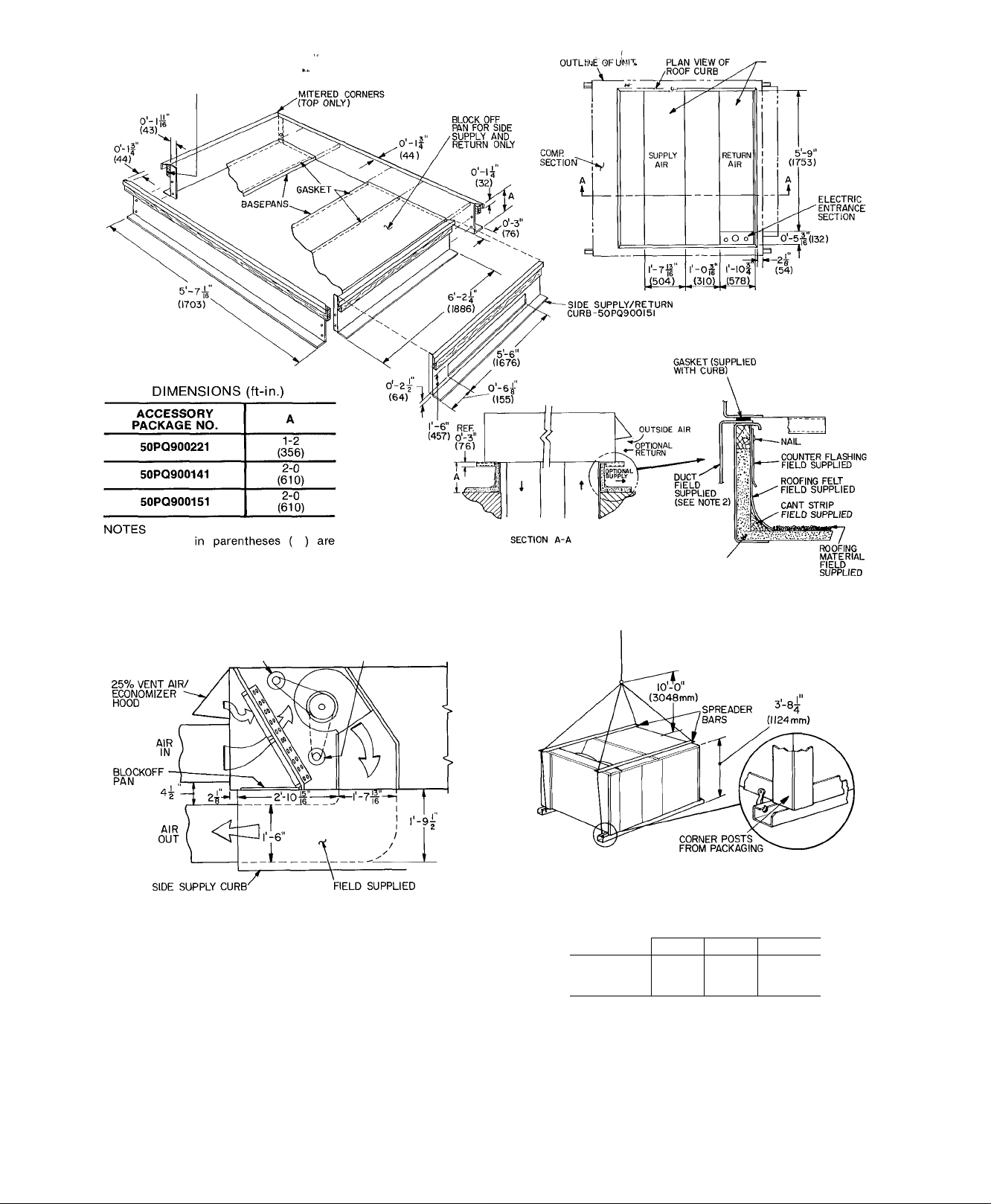
Step 2 — Rig and Place Unit — Inspect unit for
transportation damage. File any claim with transporta
tion agency. Do not drop unit, keep upright. Use spreader
bars over unit to prevent sling or cable damage. Rollers
may be used to move unit aeross a roof. Level by using
unit frame as a reference; leveling toleranee is ± 1/16 in.
per linear ft in any direction. See Fig. 3 for additional
information. Unit weight is shown in Table 1.
Four lifting holes are provided in ends of unit base rails
as shown in Fig. 3. Refer to rigging instructions on unit.
POSITIONING — Provide clearance around and above
unit for airflow, safety and service access (Fig. 4).
Manufacturer reserves the right to discontinue, or change at any time, specifications or designs without notice and without incurring obligations.
Book|l l4 PC111 Catalog No 565-104 PrintedinUSA Form 50DP-26SI Pg 1 7-88 Replaces: 50DP-25S1
Tab |1b|6b
NOM I^"x4"
(32) X (102)
TYP. 4 PLACES
ROOF OPENINGS
Dimensions
miilimeters.
Attach aii ductwork to roof curb
Fieid installation of sidewall insulation
is mandatory
Fig. 1 — Roof Curb Details
INDOOR AIR
FAN MOTOR
(50PQ900I5I)
INDOOR AIR
FAN MOTOR
50DP020
TRANSITION DUCT
Fig. 2 — Side Supply/Return Curb Details
Do not install unit in an indoor location. Do not locate
unit air inlets near exhaust vents or other sources of
contaminated air.
Although unit is weatherproof, guard against water
from higher level runoff and overhangs.
ROOF MOUNT — Check building codes for weight dis
tribution requirements. Unit weight is shown in Table 1.
INSULATION FIELD SUPPLIED
(SEE NOTE 3)
RIGGING WEIGHTS* (lb)
COIL FIN MATERIAL
MODEL
50DPE014 1880 1960
50DP016
50DP020
'Includes economizer weight
NOTE Rig by inserting hooks Into unit base rails as shown Main
tain a distance of 120 in (3048 mm) from top of unit to eyehook
Use corner post from packaging to protect coil of unit from
damage by rigging cable. Use bumper boards for spreader bars
OUTDOOR/INDOOR
AI/AI
1880 1960
2390
Cu/AI Cu/Cu
2520 2630
2040
2040
CAUTION!
All panels must be in place when rigging.
Fig. 3 — Rigging Details
©
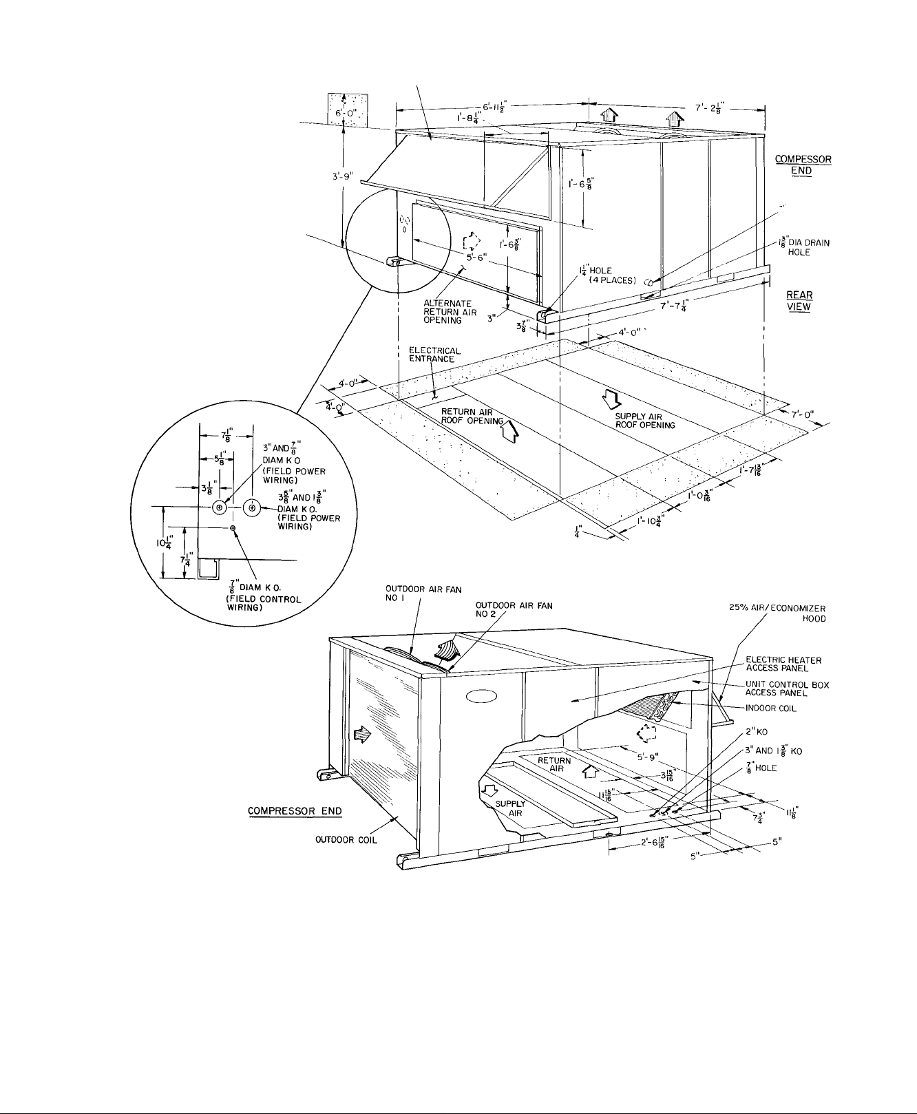
25% AIR OR ECONOMIZER HOOD
% FPT DRAIN
CONNECTION
INDOOR AIRFLOW
0
' OUTDOOR AIRFLOW
> ALTERNATE AIRFLOW
Fig- 4 — Physical Data and Dimensions
FRONT VIEW
I SPACE REQUIRED FOR
LLiia SERVICE AND AIRFLOW
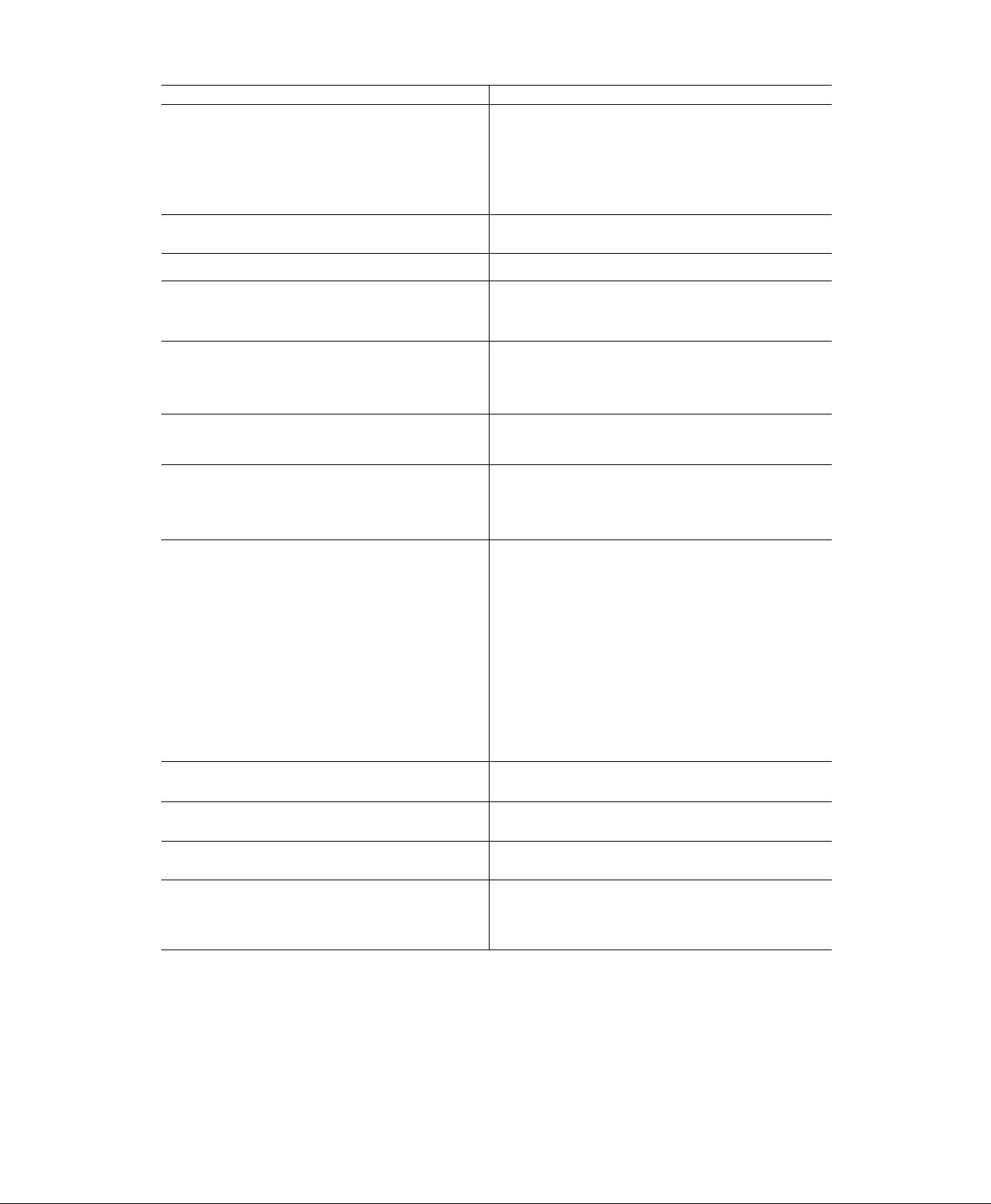
Table la — Physical Data — 50DPE014
UNIT SIZE
OPERATING WEIGHT (lb)
Unit (Outdoor Coil/Indoor Coil)
AI/AI
Al/Cu
Cu/Cu
Roof Curb
Economizer
Electric Heat
Alternate Motor and Drive
COMPRESSOR
Quantity 1
Oil (oz)
REFRIGERANT
Charge (lb) Sys 1*, Sys 2
REFRIGERANT METERING DEVICE
Upper Circuit
Quantity...Length...lD/OD (in.)
OUTDOOR COIL
Rows
Fins/in.
Aluminum
Copper
Total Face Area (sq ft)
OUTDOOR AIR FAN
Nominal Cfm
Quantity...Diameter (in.) 2 ..26
Motor Hp (1075 Rpm)
INDOOR COIL
Rows
Fins/in.
Aluminum
Copper
Total Face Area (sq ft)
INDOOR AIR FANf
Quantity...Size (in.)
Nominal Cfm
Max Allowable Rpm
Motor Pulley Pitch Diameter (in.) Std
Fan Pulley Pitch Diameter (in.)
Belt, Quantity...Type...Length (in.)
Speed Change per Full Turn Std 58
of Moveable Pulley Flange (Rpm) Opt
Moveable Pulley Max Full Turns
from Closed Position
Factory Setting — Full Turns Open
Factory Speed Setting (Rpm) Std
Motor Hp (Service Factor) Std
HIGH-PRESSURE SWITCH
Cutout (psig)
Reset (psig)
LOW-PRESSURE SWITCH (Liquid Line)
Cutout (psig)
Reset (psig)
Rpm Range Std
Opt 978-1265
Opt
Opt
Opt
Copper Tube, Aiuminum or Copper Plate Fins
Copper Tube, Aluminum or Copper Plate Fins
AIR INLET SCREENS
Economizer, Number...Size (in.)
INDOOR AIR FILTERS (Type)
10% Efficient — Disposable Fiberglass
50DPE014
Semi-Hermetic — 6 Cyiinders
Capiilary Tubes
6 25 0 055/0 125
6 25 0 055/0 125
6.25,0 055/0 125
Propeller Type, Direct Drive
Centrifugal, Belt Drive
2 20x25x1
1 20x20x1
1470
1550
1630
200
110
65
5
160
20 8
3
136
124
189
12,000
1
3
14.3
13 1
165
2 .10x10
5000
805-1093
1550
2 8-3.8
3 4-4.4
6.0
1. V. 43
57
3
920
1092
2 (1 15)
3 {1 15)
428
320
27
60
Number...Size (in.) 2. 20x20x2
'System 1 consists of upper portion of outdoor coii and iower portion of indoor coii
tUnits have adjustable standard and alternate drives
3 . 16x20x2
2 16x25x2
4
i
Table 1b — Physical Data — 50DP016,020
UNIT SIZE
OPERATING WEIGHT (lb)
Unit (Outdoor Coil/Indoor Coil)
AI/AI
Al/Cu
Cu/Cu
Roof Curb
Economizer
Electric Heat
COMPRESSOR Semi-Hermetic — 6 Cylinders
Quantity 1 2
Oil (oz)
REFRIGERANT
Charge (lb) Sys 1*, Sys 2
REFRIGERANT METERING DEVICE
Upper Circuit
Quantity...Length...ID/OD (in.)
Lower Circuit
Quantity...Length...ID/OD (in.) —
OUTDOOR COIL
Rows
Fins/in.
Aluminum
Copper
Total Face Area (sq ft)
OUTDOOR AIR FAN
Nominal Cfm
Number...Diameter (in.)
Motor Hp (1075 Rpm)
INDOOR COIL
Rows
Fins/in.
Aiuminum
Copper
Totai Face Area (sq ft)
INDOOR AIR FANf
Quantity...Size (in.)
Nominai Cfm
Rpm Range Std
Maximum Aliowable Rpm
Motor Puiiey Pitch Diameter (in.) Std
Fan Pulley Pitch Diameter (in.)
Belt, Quantity...Type...Length (in.)
Speed Change per Full Turn Std
of Moveable Pulley Flange (Rpm) Opt
Moveable Pulley Max Full Turns
from Closed Position
Factory Setting — Full Turns Open
Factory Speed Setting (Rpm) Std
Motor Hp (Service Factor) Std
HIGH-PRESSURE SWITCH
Cutout (psig)
Reset (psig)
Opt
Puiley A
Puiiey B
Opt
Pulley A
Pulley B
Opt
Pulley A
PulleO B
Opt
LOW-PRESSURE SWITCH (Liquid Line)
Reset (psig)
AIR INLET SCREENS
Economizer, Number...Size (in.)
INDOOR AIR FILTERS (Type)
Number...Size (in.)
50DP016
1470 1980
1550 2110
1630
160
R-22
21.2
6.40. 0.065/0 125
6..2 0.0 055/0.125
6.20 0 055/0 125
Copper Tubes, Aluminum or Copper Plate Fins
3
136
12.4
18.9
12,000
2 .26
1
Copper Tubes, Aluminum or Copper Plate Fins
3
143
13 1
16.5
2 ..10x10
6000
916-1186
1158-1428
— 848
—
1550
3 4-4 4
4 3-5 3
—
—
6.4
1. .V...45
54 —
55 —
3.5
970 —
1240
— 848
—
3 (1 15)
—
10% efficient — Disposable Fiberglass
2 20x20x2
3. 16x20x2
2. .16x25x2
Propeller Type, Direct Drive
200
110
65
Capillary Tubes
Centrifugal, Belt Drive
428
320
97
60
2. .20x25x1
1...20x20x1
13.25.0 055/0 125
13 .25 ..0 055/0.125
50DP020
2220
160 ea
R-22
17.0, 17.0
4
13.6
12.4
22.2
11,400
2. ,26
1
4
14.4
13.1
17.9
2 .12x12
7200
—
—
1060
1550
—
—
32
40
6.6
2 V..45
—
—
1060
5 (1 15)
—
4 20x20x2
4.. 16x20x2
c
•System 1 consists of upper portion of outdoor coil and lower
portion of indoor coil, except forsize020 which is intertwined
t016 unit has adjustable standard and alternate drives The 020
unit does not have an aiternate drive, but has 2 non-adjustable
pulieys Pulley A is instailed in unit, pulley B is shipped with unit
 Loading...