

Carrier 48XZN060130300, 48XZN060115300, 48XZN048130300, 48XZN048115300, 48XZN042090300 Installation Guide
...
Installation Instructions
NOTE: Read the entire instruction manual before starting the
installation.
NOTE: Installer: Make sure the Owner's Manual and Service
Instructions are left with the unit after installation.
TABLE OF CONTENTS
PAGE
SAFETY CONSIDERATIONS ......................... 1
INTRODUCTION ................................... 2
RECEIVING AND INSTALLATION ................. 2-13
Check Equipment .................................. 2
Identify Unit .................................... 2
Inspect Shipment ................................. 2
Provide Unit Support ............................... 2
Roof Curb ...................................... 2
Slab Mount ..................................... 2
Ground Mount .................................. 2
Field Fabricate Ductwork ............................ 2
Provide Clearances ................................. 2
Rig and Place Unit ................................. 4
Connect Condensate Drain ........................... 7
Install Flue Hood ................................... 7
Install Gas Piping ............................... 7-10
Install Duct Connections ............................ 10
Configuring Units for Downflow (Vertical)
Discharge ..................................... 10
Install Electrical Connections ........................ 11
High-Voltage Connections ........................ 11
Special Procedures for 208-V Operation .............. 12
Control Voltage Connections ....................... 12
Balance Point Setting Thermidistat or Hybrid Heat
Thermostat .................................... 12
Easy Select TM . .................................. 13
Transformer Protection ........................... 15
PRE-START-UP ................................... 15
START-UP ..................................... 16-19
Check for Refrigerant Leaks ......................... 16
Unit Sequence of Operation ......................... 16
Start-Up Heating and Make Adjustments ............... 17
Checking Heating Control ......................... 17
Start-Up Cooling and Make Adjustments ............. 18
Checking Cooling Control Operation ................ 19
MAINTENANCE ................................ 24-26
Air Filter ........................................ 24
Indoor Blower and Motor ........................... 24
Flue Gas Passageways .............................. 25
Combustion Air Blower ............................ 25
Limit Switch ..................................... 25
Burner Ignition ................................... 25
Main Burners .................................... 25
Outdoor Coil, Indoor Coil, & Condensate Drain Pan ...... 26
Outdoor Fan ..................................... 26
®
Turn to the Expertg
C99088
Fig. 1 - Unit 48XZ
Electrical Controls and Wiring ....................... 26
Refrigerant Circuit ................................. 27
Gas Input ........................................ 27
Indoor Airflow ................................... 27
Check Defrost Thermostat ........................... 27
Puron® Items .................................... 27
TROUBLESHOOTING .............................. 30
START-UP CHECKLIST ............................ 30
SAFETY CONSIDERATIONS
Improper installation, adjustment, alteration, service maintenance,
or use can cause explosion, fire, electrical shock, or other
conditions which may cause death, personal injury, or property
damage. Consult a qualified installer, service agency, or your
distributor or branch for information or assistance. The qualified
installer or agency must use factory-authorized kits or accessories
when modifying this product. Refer to the individual instructions
packaged with the kits or accessories when installing.
Follow all safety codes. Wear safety glasses, protective clothing,
and work gloves. Have a fire extinguisher available. Read these
instructions thoroughly and follow all warnings or cautions
included in literature and attached to the unit. consult local
building codes, the current editions of the National Fuel Gas Code
(NFGC) NFPA 54/ANSI Z223.1, and the National Electrical Code
(NEC) NFPA 70.
In Canada refer to the current editions of the National Standards of
Canada CAN/CSA-BI49.1 and .2 Natural Gas and Propane
Installation codes, and Canadian Electrical Code CSA C22.1

/
Recognize safety information. This is the safety-alert symbol /_.
When you see this symbol on the unit and in instructions or manu-
als, be alert to the potential for personal injury. Understand these
signal words: DANGER, WARNING, and CAUTION. These
words are used with the safety-alert symbol. DANGER identifies
the most serious hazards which will result in severe personal injury
or death. WARNING signifies hazards which could result in per-
sonal injury or death. CAUTION is used to identify unsafe practic-
es which may result in minor personal injury or product and prop-
erty damage. NOTE is used to highlight suggestions which will
result in enhanced installation, reliability, or operation.
ELECTRICALSHOCK HAZARD
Failure to follow this warning could result in personal
injury or death.
Before installing or servicing system, always turn off main
power to system. There may be more than one disconnect
switch. Turn off accessory heater power switch if
applicaMe.
FIRE, EXPLOSION, ELECTRICAL SHOCK AND
CARBON MONOXIDE POISONING HAZARD
Failure to follow this warning could result in personal
injury, death or property damage.
A qualified installer or agency must use only
factory-authorized kits or accessories when modifying this
product.
INTRODUCTION
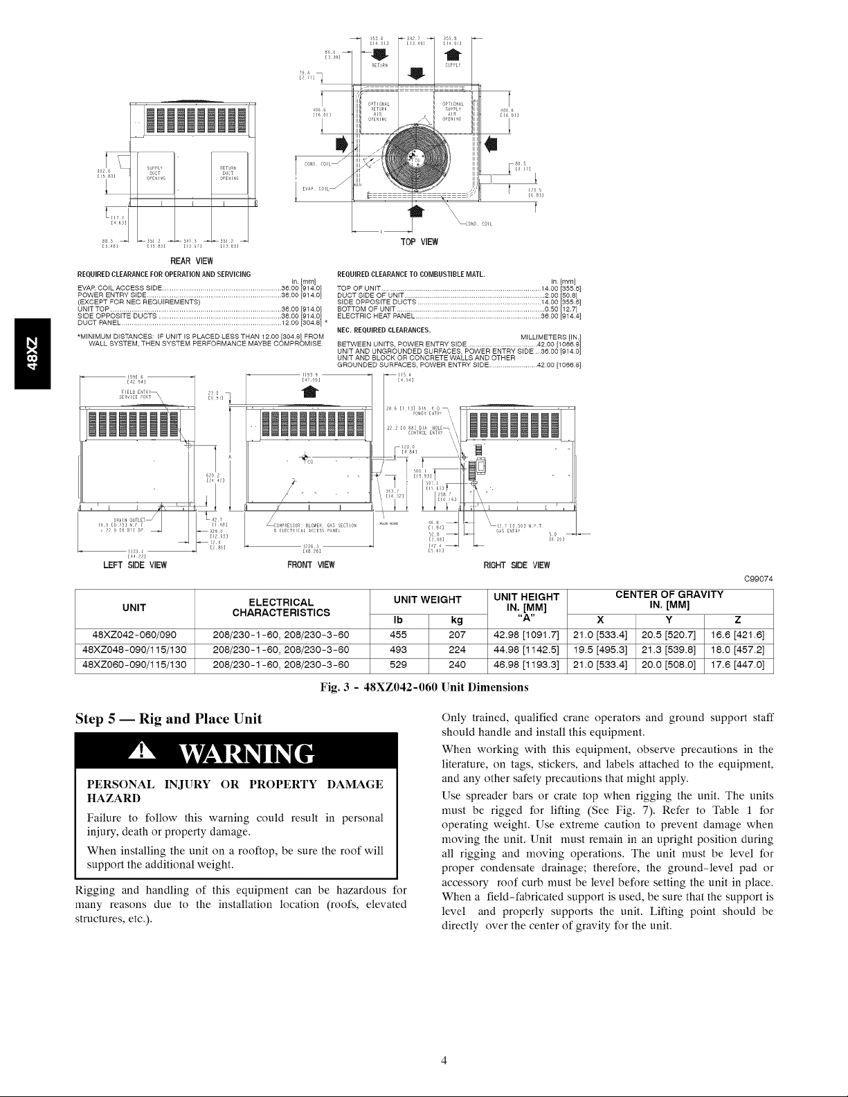
The 48XZ unit (see Fig. 1) is a fully self-contained, combination
Category I gas heating/electric cooling unit designed for outdoor
installation (See Fig. 2 and 3 for unit dimensions). All unit sizes
have return and discharge openings for both horizontal and
downflow configurations, and are factory shipped with all
downflow duct openings covered. Units may be installed either on
a rooftop, a cement slab, or directly on the ground, if local codes
permit (See Fig. 4 for roof curb dimensions).
Models with an N in the fifth position of the model number are
dedicated Low NOx units designed for California installations.
These models meet the California maximum oxides of nitrogen
(NOx) emissions requirements of 40 nanograms/joule or less as
shipped from the factory and must be installed in California Air
Quality Management Districts or any other regions in North
America where a Low NOx rule exists.
RECEIVING AND INSTALLATION
Step 1 -- Check Equipment
IDENTIFY UNIT
The unit model number and serial number are stamped on the unit
information plate. Check this information against shipping papers.
INSPECT SHIPMENT
Inspect for shipping damage while unit is still on shipping pallet. If
unit appears to be damaged or is torn loose from its anchorage,
have it examined by transportation inspectors before removal.
Forward claim papers directly to transportation company.
Manufacturer is not responsible for any damage incurred in transit.
Check all items against shipping list. Immediately notify the
nearest equipment distribution office if any item is missing. To
prevent loss or damage, leave all parts in original packages until
installation.
Step 2 -- Provide Unit Support
For hurricane tie downs, contact distributor for details and PE
(Professional Engineering) Certificate if required.
ROOF CURB
Install accessory roof curb in accordance with instructions shipped
with curb (See Fig. 4). Install insulation, cant strips, roofing, and
flashing. Ductwork must be attached to curb.
IMPORTANT: The gasketing of the unit to the roof curb is
critical for a water tight seal. Install gasketing material supplied
with the roof curb. Improperly applied gasketing also can result in
air leaks and poor unit performance.
Curb should be level to within 1/4 in. (6 mm). This is necessary for
unit drain to function properly. Refer to accessory roof curb
installation instructions for additional information as required.
SLAB MOUNT
Place the unit on a solid, level concrete pad that is a minimum of 4
in. (102 mm) thick with 2 in. (51 mm) above grade. The slab
should be flush on the compressor end of the unit (to allow
condensate drain installation) and should extend 2 in. (51 mm) on
the three remaining sides of the unit. Do not secure the unit to the
slab except when required by local codes.
GROUND MOUNT
The unit may be installed either on a slab or placed directly on the
ground, if local codes permit. Place the unit on level ground
prepared with gravel for condensate discharge.
Step 3 -- Field Fabricate Ductwork
Secure all ducts to roof curb and building structure on vertical
discharge units. Do not connect ductwork to unit. For horizontal
applications, unit is provided with flanges on the horizontal
openings. All ductwork should be secured to the flanges. Insulate
and weatherproof all external ductwork, joints, and roof openings
with counter flashing and mastic in accordance with applicable
codes.
Ducts passing through an unconditioned space must be insulated
and covered with a vapor barrier.
If a plenum return is used on a vertical unit, the return should be
ducted through the roof deck to comply with applicable fire codes.
A minimum clearance is not required around ductwork. Cabinet
return-air static shall not exceed -.25 IN. W.C..
Step 4 -- Provide Clearances
The required minimum operating and service clearances are shown
in Fig. 2 and 3. Adequate combustion, ventilation and condenser
air must be provided in accordance with section 9.3, Air for
Combustion and Ventilation, of the National Fuel Gas Code
NFPA54/ANSI Z223.1 or applicaMe provisions of local building
code. In Canada, follow sections 8.2, 8.3, or 8.5 of Can/CGA
(Canadian Gas Association) B149.1 Installation Codes or
applicaMe provisions of local building code.
IMPORTANT: Do not restrict outdoor airflow. An air restriction
at either the outdoor-air inlet or the fan discharge may be
detrimental to compressor life.
The condenser fan pulls air through the condenser coil and
discharges it through the top grille. Be sure that the fan discharge
does not recirculate to the condenser coil. Do not locate the unit in
either a corner or under an overhead obstruction. The minimum
clearance under a partial overhang (such as a normal house
overhang) is 48-in. (1219 mm) above the unit top. The maximum
horizontal extension of a partial overhang must not exceed 48-in.
(1219 mm).
Do not place the unit where water, ice, or snow from an overhang
or roof will damage or flood the unit. Do not install the unit on
carpeting or other combustible materials. The unit may be installed
on wood flooring or on Class A, B, or C roof covering materials.

O DUCT DUCT
83 ] OPEN INO OPEN I[_O
I SUPPLY [ RETURN
[317]
Y
153.3
[6041
4
I
[983] [21.67] [983]
REAR VIEW
REQ'D CLEARANCES FOR OPERATION AND SERVICING. in. (mm)
Evaporator coil access side .................. 36 (914)
Power entry side (except for NEC requirements) ......... 36 (914)
Unit top .......................... 48 (1219)
Side opposite ducts ..................... 36 (914)
Duct panel ........................ 12 (304.8)*
*Minimum distances: If unit is placed less than 12 in. (304.8 mm) from wall
system, then the system performance may be compromised.
LEGEND
CG - Center of Gravity
COND - Condenser
EVAP - Evaporator
NEC - National Electrical Code
REQ'D - Required
Note: Dimensions are in in. (mm)
[3144]
FIELD ENTRY
7_85
PORTS_\\
t
EVAP COIL •
REQ'D CLEARANCES TO COMBUSTIBLE MAT'L. in. (mm)
Top of unit ......................... 14 (355.6)
Duct side of unit ....................... 2 (50.8)
Side opposite ducts ..................... 14 (355.6)
Bottom of unit ....................... 0.50 (12.7)
Flue panel ......................... 36 (914.4)
NEC REQ'D CLEARANCES. in. (mm)
Between units, power entry side .............. 42 (1066.8)
Unit and ungrounded surfaces, power entry side ......... 36 (914)
Unit and block or concrete walls and other grounded
surfaces, control box side ................. 42 (1066.8)
[47.00]
1195.9 1
TOP VIEW
_116 3
[4.58]
286 [I 13]POWERD IA"ENTRY_
CONTROL ENTRY
[4.84]
S 123.0
3_13.8 456.2[17.961 3472
il
KO.
,_oIi_N_g__OgLETJI
_8Sl,O
48XZ024-040
48XZ030-040/060
48XZ036-060/090
[32721
LEFT SIDE VIEW
UNIT
L42 F
[1681
326.5
[12.851
_72.4
[285]
ELECTRICAL
CHARACTERISTICS
208/230 - 1-60
208/230 - 1-60
208/230-1-60, 208/230-3-60
[_8.281
FRONT VIEW
UNIT WEIGHT
Ib kg
365 166
365 166
403 183
Fig. 2 - 48XZ024-036 Unit Dimensions
UNIT HEIGHT
39.021991.1]
39.021991.1]
41.0211041.9]
\
IN.[MM]
"A"
FLUE HOOD
[I.841
[ROD]
[4811
50
[0.20]
RIGHT SIDE VIEW
C99017
CENTER OF GRAVITY
IN, [aM]
X Y Z
20.0 [508] 19.3 [489] 17.6 [447]
20.0 [508] 19.3 [489] 17.6 [447]
20.0 [508] 14.0 [355.6] 13.0 [330.2]
I
REAR VIEW
REQUIRED CLEARANCE FOR OPERATION AND SERVmClNO
EVAR COIL ACCESS SIDE .............................................................. 36.00 [914.0]
POWER ENTRY SIDE ...................................................................... 36.00 1914.0]
(EXCEPT FOR NEC REQUIREMENTS)
UNIT TOP ......................................................................................... 36.00 [914.0]
SIDE OPPOSITE DUCTS ................................................................ 36.00 [914.0]
DUCT PANEL ................................................................................... 12.00 [304.8] *
*MINIMUM DISTANCES: IF UNIT IS PLACED LESS THAN 12.00 [3048[ FROM
WALL SYSTEM, THEN SYSTEM PERFORMANCE MAYBE COMPROMISE.
IIZSI
E,H 22]
LEFTSIDEVIEW
UNIT
48XZ042-060/090
48XZ048-090/115/130
48XZ060-090/115/130
CHARACTERISTICS IN. [MM]
208/230-1-60, 208/230-3-60 455 207 42.98 [1091.7]
208/230-1-60, 208/230-3-60 493 224 44.98 [1142.5]
208/230-1-60, 208/230-3-60 529 240 46.98 [1193.3]
in. [ram]
1193 9 --
FRONT VIEW RIGHTSIDE VIEW
ELECTRICAL UNIT WEIGHT UNIT HEIGHT
TOP VIEW
REQUIRED CLEARANCE TO COMBUSTIBLE MATL
TOP OF UNIT ................................................................................... 1400 [355 6]
DUCT SIDE OF UNIT ......................................................................... 200 [50.8]
SIDE OPPOSITE DUCTS ................................................................ 1400 [355 6]
BOTTOM OF UNIT ............................................................................. 050 [12.7]
ELECTRIC HEAT PANEL ................................................................. 3600 [914 4]
NEC. REQUIRED CLEARANCES.
BETWEEN UNITS, POWER ENTRY SIDE .................................... 4200 [1066 8]
UNIT AND UNGROUNDED SURFACES, POWER ENTRY SIDE 36,00 [914 0]
UNIT AND BLOCK OR CONCRETE WALLS AND OTHER
GROUNDED SURFACES, POWER ENTRY SIDE ......................... 4200 [1066 8]
E454]
MILLIMETERS [IN.]
_....
HOLE
Ib kg "A"
Fig. 3 - 48XZ042-060 Unit Dimensions
in [mm]
CENTER OF GRAVITY
X Y
21.0 [533.4] 20.5 [520.7]
19.5 [495.3] 21.3 [539.8]
21.0 [533.4] 20.0 [508.0]
C99074
IN. [aM]
Z
16.6 [421.6]
18.0 [457.2]
17.6 [447.o]
Step 5 -- Rig and Place Unit
PERSONAL INJURY OR PROPERTY DAMAGE
HAZARD
Failure to follow this warning could result in personal
iniury, death or property damage.
When installing the unit on a rooftop, be sure the roof will
support the additional weight.
Rigging and handling of this equipment can be hazardous for
many reasons due to the installation location (roofs, elevated
structures, etc.).
Only trained, qualified crane operators and ground support staff
should handle and install this equipment.
When working with this equipment, observe precautions in the
literature, on tags, stickers, and labels attached to the equipment,
and any other safety precautions that might apply.
Use spreader bars or crate top when rigging the unit. The units
nmst be rigged for lifting (See Fig. 7). Refer to Table 1 for
operating weight. Use extreme caution to prevent damage when
moving the unit. Unit nmst remain in an upright position during
all rigging and moving operations. The unit nmst be level for
proper condensate drainage; therefore, the ground-level pad or
accessory roof curb nmst be level before setting the unit in place.
When a field-fabricated support is used, be sure that the support is
level and properly supports the unit. Lifting point should be
directly over the center of gravity for the unit.

ase _,
/ Screw-.._ q_
/
/ _ Wood nailer* \
I Flashing field II1_1 II \
/ supplied _ _JD_il_- Roofcurbq
II_ill j.q_lnsulation(fieldI
I Roofing mate_al II_ii_" II supphed)/
/ fi_'dsuPP'i_--II_itl IL /
_, /l_!;i!ll II_Duetwork /
\ IIfieldsupplied/
/ base
/ ,,So,ew_
/ ,,(NOTE A) -'t
*Gasketing .._
/ outerflange _-i_z _Woodnailer, _
I Flashing field II1_111
I supplied _ _ll_J_ Roofcurb*
I Roofing matei'al II_ supplied)
I|_su_ti°,n (f!?Id
/|_::JJl I _Ductwork t
"_/\/\/\/X/7 J
Roof Curb for Small Cabinet
Note A:When unit mounting screw is used
Rettrn opening
(BXC)
48XZ024-036 14 (356) 11 (279) 16-1/2 (419)
48XZ042-060 8 (203) 16-3/16 (411 ) 17-3/8 (441)
NOTES:
retainer bracket must also be used.
Supplyopening
(Bx C)
f
A
Sho_
Suppo4
Long
Suppo4
UNIT SIZE IN. (MM) IN. (MM) IN. (MM)
1. Roof curb must be set up for unit being installed.
2. Seal strip must be applied, as required, to unit being installed.
3. Roof curb is made of 1d-gauge steel.
4. Attach ductwork to curb (flanges of duct rest on curb).
5. Insulated panels: 1-in. (25 mm) thick fiberglass 1 lb (.47 kg) density.
d. When unit mounting screw is used (see Note A), a retainer bracket must be used as well. This bracket must also be used when required by code for hurricane or seismic
conditions. This bracket is available through Micrometl.
ODS CATALOG
NUMBER
CPRFCURB006A00
CPRFCURB007A00
CPRFCURB008A00
CPRFCURB009A00
A B C
8 (203) 11 (279) 16-1/2 (419)
14 (356) 16-3/16 (411) 17-3/8 (441)
Fig. 4 - Roof Curb Dimensions
Insulated Gasket around
deck pan outer edge
_/\/\/\/X/_ /
Roof Curb for Large Cabinet
Note A:When unit mounting screw is used
retainer bracket must also be used.
R/A
2 _Gasket around
duct
\,
28-3/4 (730)
28-3/4 (730)
40-1/4 (1022)
40-1/4 (1022)
C00076
D
IN. (MM)

1 2
f
Y
4 x 3
000070
CORNER WEIGHTS (SMALL CABINET)
Unit H
Total Weight 365 166 365 166 403 183 H
Corner Weight 1 73 33 73 33 81 37 H
Corner Weight 2 57 26 57 26 63 29 H
Corner Weight 3 88 40 88 40 97 44 H
Corner Weight 4 147 67 147 67 162 73 H
024 030 036 H
Ib kg Ib kg Ib kg H
Unit
Total Weight
Corner Weight 1
Corner Weight 2
Corner Weight 3
Corner Weight 4
CORNER WEIGHTS (LARGE CABINET)
042 048 060
Ib I kg Ib I kg Ib I kg
455 I 206 493 I 224
91 I 4t 99 I 45
71 I 32 77 I 35
110 I 50 119 I 54
183 I 83 198 I 90
Fig. 5 - 48XZ Corner Weights
.._A"/ _i
DUCTS
SEAL STRIP MUST BE IN
PLACE BEFORE PLACING
UNIT ON ROOF CURB
BASEPAN SLOT (BELOW HANDHOLDS)
BEFORE RIGGING
UNIT 48XZ in. mm in.
024 19.0 482.6 18.25
030 19.0 482.6 18.25
036 20.0 508.0 19.0
042 20.0 508.0 21.25
048 20.0 508.0 21.25
060 21.0 533.4 20.0
Ib kg
400 18t
423 192
471 2t4
548 249
575 261
595 270
Fig. 6 - Suggested Rigging
AMAXIMUM SHIPPING WEIGHT
529 I 240
106 I 48
82 I 37
128 I 58
213 I 97
C99015
B
mm
463.6
463.6
482.6
539.8
539.8
508.0
HOOK
HANDHOLD
FEED
C99067
Fig. 7 - Threading Belt

UNIT FALLING HAZARD
Failure to follow this warning could result in personal
iniury or death.
Never stand beneath rigged units or lift over people.
Dedicated low NOx models MUST be installed in California Air
Quality Management Districts where a Low NOx rule exists. These
models meet the California maximum oxides of nitrogen (NOx)
emissions requirements of 40 nanograms/joule or less as shipped
from the factory.
NOTE: Low NOx requirements apply only to natural gas
installations.
PERSONAL INJURY HAZARD
Failure to follow this warning could result in personal
iniury or death.
Never exceed 200 lb (91 kg) per bracket lifting force.
PERSONAL INJURY HAZARD
Failure to follow this warning could result in personal
injury/death.
Accessory lifting kit is only to be used with Small Packaged
units which have a composite unit base with molded rigging
holds.
Step 6 -- Connect Condensate Drain
NOTE: When installing condensate drain connection be sure to
comply with local codes and restrictions.
Model 48XZ disposes of condensate water through a 3/4 in. NPT
fitting which exits through the compressor access panel (See Fig. 2
and 3 for location).
Condensate water can be drained directly onto the roof in rooftop
installations (where permitted) or onto a gravel apron in
groundlevel installations. Install a field-supplied condensate trap
at end of condensate connection to ensure proper drainage. Make
sure that the outlet of the trap is at least 1 in. lower than the
drain-pan condensate connection to prevent the pan from
overflowing (See Fig. 8). Prime the trap with water. When using a
gravel apron, make sure it slopes away from the unit.
If the installation requires draining the condensate water away
from the unit, install a 2-in. (51 mm) trap at the condensate
connection to ensure proper drainage (See Fig. 8). Make sure that
the outlet of the trap is at least 1 in. lower than the drain-pan
condensate connection. This prevents the pan from overflowing.
Prime the trap with water. Connect a drain tube - using a minimum
of 3/4-in. PVC or 3/4-in. copper pipe (all field-supplied) - at the
outlet end of the 2-in. (51 mm) trap. Do not undersize the tube.
Pitch the drain tube downward at a slope of at least l-in. (25 mm)
for every 10 ft (3 m) of horizontal run. Be sure to check the drain
tube for leaks.
1"(25 mm) MIN.
TRAP
2" (51mm) MIN.
A08001
Fig. 8 - Condensate Trap
PERSONAL INJURY AND UNIT DAMAGE HAZARD
Failure to follow this warning could result in personal injury
or death and unit component damage.
The venting system is designed to ensure proper venting. The
flue hood assembly must be installed as indicated in this
section of the unit installation instructions.
Install the flue hood as follows:
1. This installation must conform with local building codes
and with the National Fuel Gas Code (NFGC),
NFPA54/ANSI Z223.1 (in Canada, CAN/CGA B149.1, and
B149.2). Refer to Provincial and local plumbing or
wastewater codes and other applicable local codes.
2. Remove flue hood from shipping location (inside the return
section of the blower compartment-See Fig. 9). Place vent
cap assembly over flue panel. Orient screw holes in vent cap
with holes in the flue panel.
3. Secure flue hood to flue panel by inserting a single screw on
the right side and the left side of the hood.
Step 8 -- Install Gas Piping
The gas supply pipe enters the unit through the access hole
provided. The gas connection to the unit is made to the 1/2-in.
FPT gas inlet on the manual shutoff or gas valve.
Install a gas supply line that runs to the heating section. Refer to
Table 2 and the NFGC for gas pipe sizing. Do not use cast-iron
pipe. It is recommended that a black iron pipe is used. Check the
local utility for recommendations concerning existing lines. Size
gas supply piping for 0.5 IN. W.C. maximum pressure drop. Never
use pipe smaller than the l/2-in. FPT gas inlet on the unit gas
valve.
When installing the gas supply line, observe local codes pertaining
to gas pipe installations. Refer to the NFGC NFPA54/ANSI
Z223.1 (in Canada, CAN/CGA B149.1 latest edition. In the
absence of local building codes, adhere to the following pertinent
recommendations:
1. Avoid low spots in long runs of pipe. Grade all pipe 1/4 in.
(6 mm) in every 15 ft (5 m) to prevent traps. Grade all
horizontal runs downward to risers. Use risers to connect to
heating section and to meter.
2. Protect all segments of piping system against physical and
thermal damage. Support all piping with appropriate straps,
hangers, etc. Use a minimum of one hanger every 6 ft (2 m).
For pipe sizes larger than 1/2 in., follow recommendations
of national codes.
3. Apply joint compound (pipe dope) sparingly and only to
male threads of joint when making pipe connections. Use
only pipe dope that is resistant to action of liquefied
petroleum gases as specified by local and/or national codes.
Never use Teflon tape.
Step 7 -- Install Flue Hood
The flue hood assembly is shipped in the return section of the
indoor blower compartment (See Fig. 10). Remove the return duct
cover to locate the assembly.
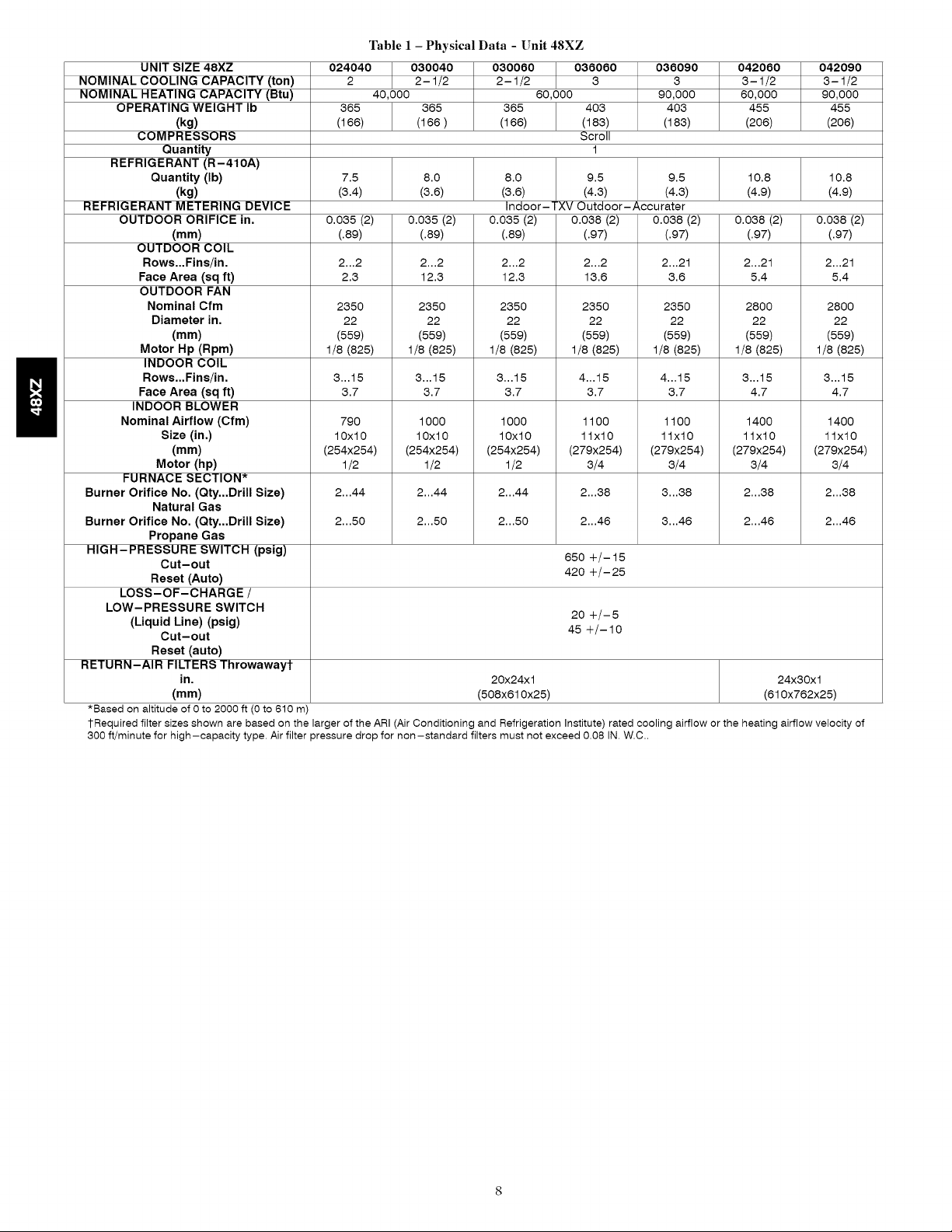
Table I - Physical Data - Unit 48XZ
UNIT SIZE 48XZ 024040 030040 030060 036060 036090 042060 042090
NOMINAL COOLING CAPACITY (ton) 2 2-1/2 2-1/2 3 3 3-1/2 3-1/2
NOMINAL HEATING CAPACITY (Btu) 40,000 80,000 90,000 80,000 90,000
OPERATING WEIGHT Ib 365 365 365 403 403 455 455
(kg) (166) (166 ) (166) (183) (183) (206) (206)
COMPRESSORS Scroll
Quantity 1
REFRIGERANT (R-410A)
Quantity (Ib) 7.5 8.0 8.0 9.5 9.5 10.8 10.8
(kg) (3.4) (3.8) (3.8) (4.3) (4.3) (4.9) (4.9)
REFRIGERANT METERING DEVICE Indoor-TXV Outdoor-Accurater
OUTDOOR ORIFICE in, 0.035 (2) 0.035 (2) 0.035 (2) 0.038 (2) 0.038 (2) 0.038 (2) 0.038 (2)
(mm) (.89) (.89) (.89) (.97) (.97) (.97) (.97)
OUTDOOR COIL
Rows.,,Fins/in, 2...2 2...2 2...2 2...2 2...21 2...21 2...21
Face Area (sq ft) 2.3 12.3 12.3 13.8 3.8 5.4 5.4
OUTDOOR FAN
Nominal Cfm 2350 2350 2350 2350 2350 2800 2800
Diameter in, 22 22 22 22 22 22 22
(mm) (559) (559) (559) (559) (559) (559) (559)
Motor Hp (Rpm) 1/8 (825) 1/8 (825) 1/8 (825) 1/8 (825) 1/8 (825) 1/8 (825) 1/8 (825)
INDOOR COIL
Rows.,,Fins/in, 3...15 3...15 3...15 4...15 4...15 3...15 3...15
Face Area (sq ft) 3.7 3.7 3.7 3.7 3.7 4.7 4.7
INDOOR BLOWER
Nominal Airflow (Cfm) 790 1000 1000 1100 1100 1400 1400
Size (in,) 10x10 10x10 10x10 1lx10 1lx10 1lx10 1lx10
(mm) (254x254) (254x254) (254x254) (279x254) (279x254) (279x254) (279x254)
Motor (hp) 1/2 1/2 1/2 3/4 3/4 3/4 3/4
FURNACE SECTION*
Burner Orifice No, (Qty,,,Drill Size) 2...44 2...44 2...44 2...38 3...38 2...38 2...38
Natural Gas
Burner Orifice No, (Qty,,,Drill Size) 2...50 2...50 2...50 2...48 3...48 2...48 2...48
Propane Gas
HIGH- PRESSURE SWITCH (psig) 850 +/- 15
Cut-out
Reset (Auto) 420 +/-25
LOSS-OF-CHARGE /
LOW-PRESSURE SWITCH 20 +/-5
(Liquid Line) (psig) 45 +/-10
Cut-out
Reset (auto)
RETURN-AIR FILTERS Throwawayt
in, 20x24xl 24x30xl
(mm) (508x810x25) (810x782x25)
*Based on altitude of 0 to 2000 ft (0 to 610 m)
1-Required filter sizes shown are based on the larger of the ARI (Air Conditioning and Refrigeration Institute) rated cooling airflow or the heating airflow velocity of
300 if/minute for high-capacity type. Air filter pressure drop for non-standard filters must not exceed 0.08 IN. W.C..

Table 1 - Physical Data - Unit 48XZ (Cont)
UNIT SIZE 48XZ 048090 048115 048130 060090 060115 060130
NOMINAL COOLING CAPACITY (ton) 4 4 4 5 5 5
NOMINAL HEATING CAPACITY (ton) 90,000 115,000 130,000 90,000 115,000 130,000
OPERATING WEIGHT Ib 493 493 493 529 529 529
(kg) (224) (224) (224) (240) (240) (240)
COMPRESSORS Scroll
Quantity 1
REFRIGERANT (R-410A)
Quantity Ib 11.5 11.5 11.5 14.0 14.0 14.0
(kg) (5.2) (5.2) (5.2) (8.4) (8.4) (8.4)
REFRIGERANT METERING DEVICE Indoor-TXV Outdoor-Accurater
OUTDOOR ORIFICE in, 0.038 (Left OD Coil) 0.046 (Right OD Coil) 0.042 (Left OD Coil) 0.052 (Right OD Coil)
(mm) (.97 Left OD Coil) (1.2 Right OD Coil) (1.1 Left OD Coil) (1.3 Right OD Coil)
OUTDOOR COIL
Rows,,,Fins/in, 2...21 2...21 2...21 2...21 I 2...21 2...21
Face Area (sq ft) 17.2 17.2 17.2 19.4 19.4 19.4
OUTDOOR FAN
Nominal Cfm 3300 3300 3300 3300 3300 3300
Diameter in, 22 22 22 22 22 22
(mm) (559) (559) (559) (559) (559) (559)
Motor Hp (Rpm) 1/4 (1100) 1/4 (1100) 1/4 (1100) 1/4 (1100) 1/4 (1100) 1/4 (1100)
INDOOR COIL
Rows,,,Fins/in, 4...15 4...15 4...15 4...15 4...15 4...15
Face Area (sq ft) 4.7 4.7 4.7 5.7 5.7 5.7
INDOOR BLOWER
Nominal Airflow (Cfm) 1450 1450 1450 1750 1750 1750
Size in. 1lx10 1lx10 1lx10 1lx10 1lx10 1lx10
(mm) (279x254) (279x254) (279x254) (279x254) (279x254) (279x254)
Motor (hp) 3/4 (1075) 3/4 (1075) 3/4 (1075) 1.0 (1040) 1.0 (1040) 1.0 (1040)
FURNACE SECTION*
Burner Orifice No. (Qty...Drill Size)
Natural Gas Burner Orifice No. 3...38 3...33 3...31 3...38 3...33 3...31
(Qty...Drill Size)
Propane Gas 3...48 3...42 3...41 3...48 3...42 3...41
HIGH- PRESSURE SWITCH (psig) 850 +/- 15
Cut-out Reset (Auto) 420 +/-25
LOSS-OF-CHARGE /
LOW-PRESSURE SWITCH
(Liquid Line) (psig) 20 +/-5
Cut-out Reset (auto) 45 +/- 10
RETURN-AIR FILTERS Throwawayt
in. 24x30xl
(mm) (810x762x25)
*Based on altitude of 0 to 2000ft (0to 610m).
1-Required filter sizes shown are based on the larger of the ARI (Air Conditioning and Refrigeration Institute) rated cooling airflow or the heating airflow velocity of
300 if/minute for high-capacity type. Air filter pressure drop for non-standard filters must not exceed 0.08 IN. W.C..
IN
Fig. 9 - Sediment Trap
TEE
4. Install sediment trap in riser leading to heating section (See
Fig. 9). This drip leg functions as a trap for dirt and
condensate.
5. Install an accessible, external, manual main shutoff valve in
gas supply pipe within 6 fl (2 m) of heating section.
6. Install ground-joint union close to heating section between
unit manual shutoff and external manual main shut-off
valve.
7. Pressure-test all gas piping in accordance with local and
national plumbing and gas codes before connecting piping
to unit.
NOTE: Pressure test the gas supply system after the gas supply
piping is connected to the gas valve. The supply piping nmst be
disconnected from the gas valve during the testing of the piping
systems when test pressure is in excess of 0,5 psig, Pressure test the
gas supply piping system at pressures equal to or less than 0,5 psig,
The unit heating section nmst be isolated from the gas piping
system by closing the external main manual shutoff valve and
slightly opening the ground-joint union.
C99020

Table2- MaximumGas Flow Capacity*
NOMINAL INTERNAL LENGTH OF PIPE, FT (M)I
IRON PIPE, DIAMETER 10 20 30 40 50 60 70 80 90 100 125 150 175 200
SIZE (IN.) (IN.) (3) (6) (9) (12) (15) (18) (21) (24) (27) (30) (38) (46) (53) (61)
1/2 .622 175 120 97 82 73 66 61 57 53 50 44 40 -- --
3/4 .824 360 250 200 170 151 138 125 118 110 103 93 84 77 72
1 1.049 680 465 375 320 285 260 240 220 205 195 175 160 145 135
1 1/4 1.380 1400 950 770 600 580 530 490 460 430 400 360 325 300 280
1 1/2 1.610 2100 1460 1180 990 900 810 750 690 650 620 550 500 460 430
* Capacity of pipe in cu ft of gas per hr for gas pressure of 0.5 psig or less. Pressure drop of 0.5-IN. W.C. (based on a 0.60 specific gravity gas). Refer to Table,
National Fire Protection Association NFPA 54.1 This length includes an ordinary number of fittings.
Table 3 - Heating Inputs
HEATING
INPUT (BTUH)*
40,000
60,000
90,000
115,000
130,000
* When a unit is converted to propane, different size orifices must be used. See separate, natural-to-propane conversion kit instructions.
1 Based on altitudes from sea level to 2000 ff above sea level. For altitudes above 2000 ff, reduce input rating 4 percent for each additional 1000 ff above sea level.
In Canada, from 2000 ff above sea level to 4500 ff above sea level, de-rate the unit 10 percent.
NUMBER OF
ORIFICES
2
2
3
3
3
GAS SUPPLY PRESSURE (IN. W.C.)
Natural Propanel-
Min
4.0
4.0
4.0
4.0
4.0
Max Min
13.0 4.0
13.0 4.0
13.0 4.0
13.0 4.0
13.0 4.0
Max
13.0
13.0
13.0
13.0
13.0
Table 4 - Air Delivery (Cfm) at Indicated Temperature Rise and Rated Heating Input
HEATING
INPUT
(BTUH)
40,000
60,000
90,000
115,000
130,000
20 25
(11) (14)
1500 1200
2250 1800
30 35 40 45 50 55 60 65 70
(17) (19) (22) (25) (28) (31) (33) (36) (39)
1000 857 750 667 600 545 500 -- --
1500 1286 1125 1000 900 818 750 692 --
2250 1929 1688 1500 1350 1227 1125 1038 964
-- 2464 2156 1917 1725 1568 1438 1327 1232
-- 2786 2438 2167 1950 1773 1625 1500 --
TEMPERATURE RISE °F (°C)
MANIPOLDq:rREssURE
(IN. W.C.)
Natural Propane1-
3.5 3.5
3.5 3.5
3.5 3.4
3.5 3.7
3.5 3.5
FIRE OR EXPLOSION HAZARD
Failure to follow this warning could result in personal iniury,
death and/or property damage.
-Connect gas pipe to unit using a backup wrench to avoid
damaging gas controls.
-Never purge a gas line into a combustion chamber. Never test
for gas leaks with an open flame. Use a commercially available
soap solution made specifically for the detection of leaks to
check all connections.
-Use proper length of pipe to avoid stress on gas control
manifold.
-If a flexible connector is required or allowed by authority
having jurisdiction, black iron pipe shall be installed at furnace
gas valve and extend a nfininmm of 2 in. (51 ram) outside
furnace casing.
-If codes allow a flexible connector, always use a new
connector, do not use a connector which has previously
serviced another gas appliance.
8. Check for gas leaks at the field-installed and
factoryinstalled gas lines after all piping connections have
been completed. Use a commercially available soap solution
made specifically for the detection of leaks.
Step 9 -- Install Duct Connections
The unit has duct flanges on the supply- and return-air openings
on the side and bottom of the unit. For downshot applications, the
ductwork connects to the roof curb (See Fig. 2 and 3 for
connection sizes and locations).
CONFIGURING UNITS FOR DOWNFLOW
_VERTICAL) DISCHARGE
ELECTRICALSHOCK HAZARD
Failure to follow this warning could result in personal iniury
or death.
Before installing or servicing system, always turn off main
power to system. There may be more than one disconnect
switch.
1. Open all electrical disconnects before starting any servace
work.
2. Remove horizontal (metal) duct covers to access vertical
(downflow) discharge duct knockouts in unit base.
3. Use a screwdriver and hammer to remove the panels in the
bottom of the unit base (See Fig. 10 & 11).
4. If unit ductwork is to be attached to vertical opening flanges
on the unit base (jackstand applications only), do so at this
time.
PROPERTY DAMAGE HAZARD
Failure to follow this caution may result in property damage.
Collect ALL screws that were removed. Do not leave screws
on rooftop as permanent damage to the roof may occur.
10

/
SUPPLY RETURN
DUCT DUCT
OPENING OPENING
C99011
Fig. 10 - Supply and Return Duct Opening
5. It is recommended that the base insulation around the
perimeter of the vertical return-air opening be secured to
the base with aluminum tape. Applicable local codes may
require aluminum tape to prevent exposed fiberglass.
6. ('over both horizontal duct openings with the provided
duct covers. Ensure opening is air- and watertight.
7. After completing unit conversion, perform all safety checks
and power up unit.
NOTE: The design and installation of the duct system must be in
accordance with the standards of the NFPA for installation of
nonresidence-type air conditioning and ventilating systems, NFPA
90A or residence-type, NFPA 90B; and/or local codes and
ordinances.
Adhere to the following criteria when selecting, sizing, and
installing the duct system:
1. Units are shipped for horizontal duct installation (by
removing duct covers).
2. Select and size ductwork, supply-air registers, and
return-air grilles according to American Society of Heating,
Refrigeration and Air Conditioning Engineers (ASHRAE)
recommendations.
3. Use flexible transition between rigid ductwork and unit to
prevent transmission of vibration. The transition may be
screwed or bolted to duct flanges. Use suitable gaskets to
ensure weather tight and airtight seal.
4. All units must have field-supplied filters or accessory filter
rack installed in the return-air side of the unit.
Recommended sizes for filters are shown in Table 1.
5. Size all ductwork for maximum required airflow (either
heating or cooling) for unit being installed. Avoid abrupt
duct size increases or decreases or performance may be
affected.
6. Adequately insulate and weatherproof all ductwork located
outdoors. Insulate ducts passing through unconditioned
space, and use vapor barrier in accordance with latest issue
of Sheet Metal and Air Conditioning Contractors National
Association (SMACNA) and Air Conditioning Contractors
of America (ACCA) minimum installation standards for
heating and air conditioning systems. Secure all ducts to
building structure.
7. Flash, weatherproof, and vibration-isolate all openings in
building structure in accordance with local codes and good
building practices.
Step 10 -- Install Electrical Connections
ELECTRICAL SHOCK HAZARD
Failure to follow this warning could result in personal iniury
or death.
The unit cabinet must have an uninterrupted, unbroken
electrical ground. This ground may consist of an electrical
wire connected to the unit ground screw in the control
compartment, or conduit approved for electrical ground when
installed in accordance with NEC, NFPA 70 (latest edition) (in
Canada, Canadian Electrical Code CSA C22.1) and local
electrical codes.
UNIT COMPONENT DAMAGE HAZARD
Failure to follow this caution could result in damage to the unit
being installed.
1. Make all electrical connections in accordance with NEC
NFPA 70 (latest edition) and local electrical codes
governing such wiring. In Canada, all electrical
connections must be in accordance with CSA standard
C22.1 Canadian Electrical Code Part 1 and applicable
local codes. Refer to unit wiring diagram.
2. Use only copper conductor for connections between
field-supplied electrical disconnect switch and unit. DO
NOT USE ALUMINUM WIRE.
3. Be sure that high-voltage power to unit is within
operating voltage range indicated on unit rating plate. On
3-phase units, ensure phases are balanced within 2
percent. Consult local power company for correction of
improper voltage and/or phase imbalance.
4. Insulate low-voltage wires for highest voltage contained
within conduit when low-voltage control wires are in
same conduit as high-voltage wires.
5. Do not damage internal components when drilling
through any panel to mount electrical hardware, conduit,
etc.
HIGH-VOLTAGE CONNECTIONS
The unit must have a separate electrical service with a
field-supplied, waterproof, disconnect switch mounted at, or
within sight from, the unit. Refer to the unit rating plate for
maximum fuse/circuit breaker size and minimum circuit amps
(ampacity) for wire sizing.
The field-supplied disconnect switch box may be mounted on the
unit over the high-voltage inlet hole when the standard power and
low-voltage entry points are used (See Fig. 2 and 3 for acceptable
location).
See unit wiring label and Fig. 11 for reference when making high
voltage connections. Proceed as follows to complete the high
voltage connections to the unit.
Single phase units:
1. Run the high-voltage (L1, L2) and ground leads into the
control box.
2. Connect ground lead to chassis ground connection.
3. Connect L1 to pressure lug connection 11 of the compressor
contactor.
4. Connect L2 to pressure lug connection 23 of the
compressor contactor.
11
 Loading...