

Carrier 48TF004-007 User Manual
Installation, Start-Up, and
Service Instructions
CONTENTS
Page
SAFETY CONSIDERATIONS
INSTALLATION
Step 1 — Provide Unit Support
•ROOF CURB
• SLAB MOUNT
Step 2 — Field Fabricate Ductwork
Step 3 — In stall Exte rnal Trap for Condensate
. . . . . . . . . . . . . . . . . . . . . . . . . . . . . . . . . . . . . . . . . . . 2
Drain
Step 4 — Rig and Place Unit
• POSITIONING
Step 5 — Install Flue Hood
Step 6 — Install Gas Piping
Step 7 — Make Electrical Connections
• FIELD POWER SUPPLY
• FIELD CONTROL WIRING
• HEA T ANTICIPATOR SETTINGS
Step 8 — Make Outdoor-Air Adjustments
and Install Outdoor-Air Hood
• MANUAL OUTDOOR-AIR DAMPER
• OPTIONAL DURABLADE ECONOMIZER
• OPTIONAL ECONOMI$ER
Step 9 — Adjust Evaporator-Fan Speed
• DIRECT-DRIVE MOTORS
• BELT-DRIVE MOTORS
ST ART-UP
SERVICE
TROUBLESHOOTING
START-UP CHECKLIST
. . . . . . . . . . . . . . . . . . . . . . . . . . . . . . . . 1-35
. . . . . . . . . . . . . . . . . . . . . . . . . . . . . . . . . . . . 36-38
. . . . . . . . . . . . . . . . . . . . . . . . . . . . . . . . . . . . . 38-43
. . . . . . . . . . . . . . . . . . . . . . . . . 44-49
SAFETY CONSIDERATIONS
Installation and servicing of air-conditioning equipment can
be hazardous due to system pressure and electrical components. Only trained and qualified service personnel should
install, repair, or service air-conditioning equipment.
Untrained personnel can perform basic maintenance functions of cleaning coils and filters and replacing filters. All other
operations should be performed by trained service personnel.
When working on air-conditioning equipment, observe precautions in the li terature, tag s and labels attached to t he unit, and
other safety precautions that apply.
Follow all safety codes. Wear safety glasses and work
gloves. Use quenching cloth for unbrazing operations. Have
fire extinguishers available for all brazing operations.
. . . . . . . . . . . . . . . . . . . . . . 1
. . . . . . . . . . . . . . . . . . . 1
. . . . . . . . . . . . . . . 2
. . . . . . . . . . . . . . . . . . . . . 2
. . . . . . . . . . . . . . . . . . . . . . . 4
. . . . . . . . . . . . . . . . . . . . . . 4
. . . . . . . . . . . 8
. . . . . . . . . . . . . . . . . . 11
. . . . . . . . . 19
. . . . . . . . . . . . . . . . . . . . . . . .CL-1
48TF004-007
Single-Package Rooftop
Heating/Cooling Units
Disconnect gas piping from unit when leak
testing at pressure greater than 1/2 psig.
Pressures greater than 1/2 psig will cause
gas valve damage resulting in hazardous
condition. If gas valve is subjected to pressure greater than
replaced before use. When pressure testing
field-supplied gas piping at pressures of
1
/2 psig or less, a unit connected to such
piping must be isolated by manually cl osing
the gas valve.
Before performing service or maintenance operations on
unit, turn off main power switch to unit and install a lockout tag. Electrical shock could cause personal injury.
INSTALLATION
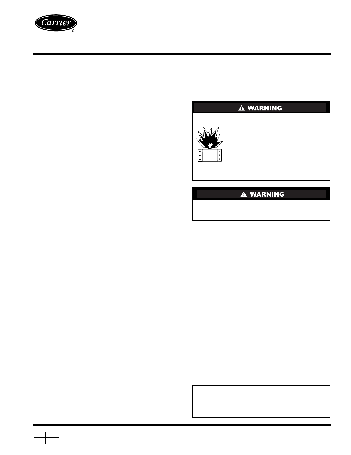
Unit is shipped in the vertical duct configuration. To convert
to horizontal configuration, remove screws from side duct
opening covers and remove covers. Using the same screws, install covers on vertical duct openings with the insulation-side
down. Seals around duct openings must be tight. See Fig. 1.
Confirm before installation of unit that voltage, amperage
and circuit protection requirements listed on unit data plate
agree with power supply provided.
Step 1 — Provide Unit Support
ROOF CURB — Assemb le and install accessor y roof cu rb in
accordance with instructions shipped with curb. See Fig. 2. Install insulation, cant strips, roofing felt, and counter flashing as
shown. Ductwork must be attached to curb, not to the unit. The
accessory thru-the-bottom power and gas connection package
must be installed before the unit is set on the roof curb. If field-
installed (thru-the-roof curb) gas connections are desired, use
factory-supplied
mount the thru-the-roof curb connection to the roof curb. Gas
connections and power connections to the unit must be field installed after the unit is installed on the roof curb.
If electric and control wiring is to be routed through the
basepan, attach the accessory thru-the-bottom service connections to the basepan in accordance with the accessory installation instructions.
3
/4-in. pipe coupling and gas plate assembly to
1
/2 psig, it must be
IMPORTANT: The gasketing of the unit to the roof curb
is critical for a watertight seal. Install gasket supplied
with the roof curb as shown in Fig. 2. Improperly
applied gasket can result in air leaks and poor unit
performance.
Manufacturer reserves the right to discontinue, or change at any time, specifications or designs without notice and without incurring obligations.
Book 1 4
Ta b 1 a 6 a
PC 111 Catalog No. 534-80000 Printed in U.S.A. Form 48TF-1SI Pg 1 8-00 Replaces: New
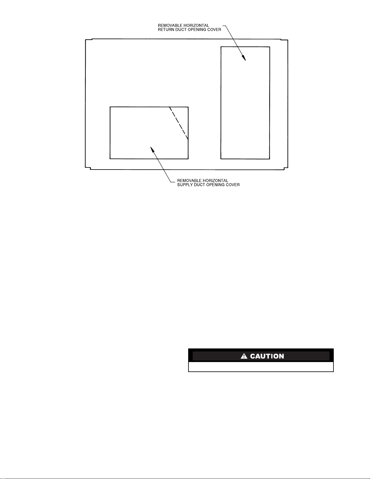
Fig. 1 — Horizontal Conversion Panels
Curb should be level. Unit leveling tolerances are shown in
Fig. 3. This is necessary for unit drain to function properly. Refer to Accessory Roof Curb Installation Instructions for additional information as required.
SLAB MOUNT (Horizontal Units Only) — Provide a level
concrete slab that extends a minimum of 6 in. beyond unit
cabinet. Install a gravel apron in front of condenser coil air inlet
to prevent grass and foliage from obstructing airflow .
NOTE: Horizontal units may be installed on a roof curb if
required.
Step 2 — Field Fabricate Ductwork —
Secure all
ducts to roof curb and building structure on vertical ducted
units. Do not connect ductwork to unit. For horizontal applica-
tions, field-supplied flanges should be attached to horizontal
duct openings and all ductwork should be secured to the
flanges. Insulate and weatherproof all external ductwork,
joints, and roof openings with counter flashing and mastic in
accordance with applicable codes.
Ducts passing through an unconditioned space must be in-
sulated and covered with a vapor barrier.
If a plenum return is used on a vertical unit, the return
should be ducted through the roof deck to comply with applicable fire codes.
A minimum clearance is not required around ductwork.
Cabinet return air static shall not exceed –.20 in. wg with
EconoMi$er, –.35 in. wg with Durablade economizer, or
–.45 in. wg without economizer.
These units are designed for a minimum continuous heating
return-air temperature of 50 F (dry bulb), or an intermittent operation down to 45 F (dry bulb), such as when used with a night
set-back thermostat.
Step 3 — Install External Trap for Condensate
Drain —
located on the bottom and side of the unit. Unit discharge connections do not determine the use of drain connections; either
drain connection can be used with vertical or horizontal
applications.
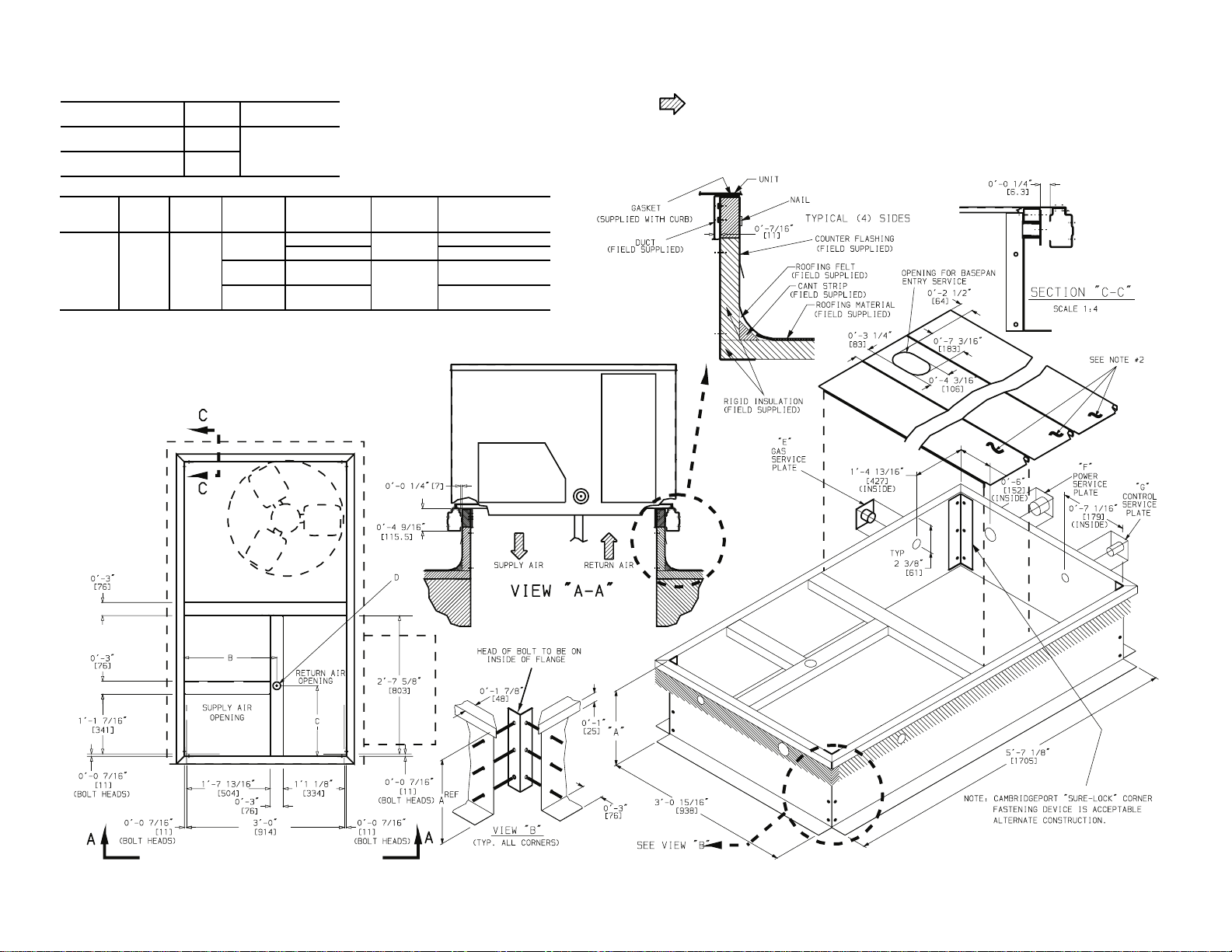
The unit’s 3/4-in. condensate drain connections are
When using the standard side drain connection, make sure
the plug (Red) in the alternate bottom connection is tight before
installing the unit.
To use the bottom drain connection for a roof curb installation, relocate the factory-installed plug (Red) from the bottom
connection to the side connection. See Fig. 4. The piping for
the condensate drain and external trap can be completed after
the unit is in place.
All units must have an external trap for condensate drainage. Install a trap at least 4-in. deep and protect agai nst freez eup. If drain line is installed downstream from the external trap,
pitch the line away from the unit at 1 in. per 10 ft of run. Do not
use a pipe size smaller than the unit connection (
Step 4 — Rig and Place Unit —
3
/4 in.).
Inspect unit for
transportation damage. File any claim with transportation
agency. Keep unit upright and do not drop. Spreader bars are
not required if top crating is left on unit. Rollers may be used to
move unit across a roof. Level by using unit frame as a reference. See Table 1 and Fig. 5 for additional information.
Lifting holes are provided in base rails as shown in Fig. 6.
Refer to rigging instructions on unit.
All panels must be in place when rigging.
POSI TION I NG — Maintain clearance around and above unit
to provide minimum distance from combustible materials,
proper airflow, and service access. See Fig. 6. A properly positioned unit will have the following clearances between unit and
roof curb:
1
/4-in. clearance between roof curb and base rails on
each side and duct end of unit; 1/4-in. clearance between roof
curb and condenser coil end of unit. (See Fig. 2, section C-C.)
Do not install unit in an indoor location. Do not locate unit
air inlets near exhaust vents or other sources of contaminated
air.
Be sure that unit is installed such that snow will not block
the combustion intake or flue outlet.
2
ROOF CURB
ACCESSORY
CRRFCURB001A00
CRRFCURB002A00
A UNIT SIZE
1′-2″
[356]
2′-0″
[610]
48TF004-007
NOTES:
1. Roof curb accessory is shipped disassembled.
2. Insulated panels.
3. Dimensions in [ ] are in millimeters.
4. Roof curb, galvanized steel.
5. Attach ductwork to curb (flanges of duct rest on curb).
6. Service clearance: 4 ft on each side.
7. Direction of airflow.
8. Connector packages CR BTMPWR001A00 and 002A00 a re for thru-thecurb connections. Packages CRBTMPWR003A00 and 004A00 are for
thru-the-bottom connections.
BC
11
1′-9
/16″
[551]
1′-4″
[406]
D AL T
DRAIN
HOLE
13/4″
[44.5]
“E”
GAS
3
/4″
[19] NPT
1
/2″
[12.7] NPT
3
/4″
[19] NPT
“F”
POWER
3
/4″ [19] NPT)
1
1
/4″ [31.7] CRBTMPWR002A00
3
/4″ [19] NPT
11/4″ [31.7] CRBTMPWR004A00
“G”
CONTROL
1
/2″
[12.7]
1
/2″
[12.7]
CONNECTOR
PKG. ACCY.
CRBTMPWR001A00
CRBTMPWR003A00
3
Fig. 2 — Roof Curb Dimensions
MAXIMUM ALLOWABLE
DIFFERENCE (in.)
A-B B-C A-C
0.5 1.0 1.0
Fig. 3 — Unit Leveling Tolerances
OTE: Drain plug is shown in factory-installed position.
Fig. 4 — Condensate Drain Connection
Unit may be installed directly on wood flooring or on
Class A, B, or C roof-covering material when roof curb is used.
Although unit is weatherproof, guard against water from
higher level runoff and overhangs.
Flue vent discharge must have a minimum horizontal clearance of 4 ft from electric and gas meters, gas regulators, and
gas relief equipment.
Minimum distance between unit and other electrically live
parts is 48 inches.
Flue gas can deteriorate building materials. Orient unit such
that flue gas will not affect building materials.
Adequate combustion-air space must be provided for proper
operation of this equipment. Be sure that installation complies
with all local codes and Section 5.3, Air for Combustion and
Ventilation, NFGC (National Fuel Gas Code), and ANSI
(American National Standards Institute) Z223.1, and NFPA
(National Fire Protection Association) 54 TIA-54-84-1.
In Canada, installation must be in accordance with the
CAN1-B149 installation codes for gas burning appliances.
After unit is in position, remove rigging skids and shipping
materials.
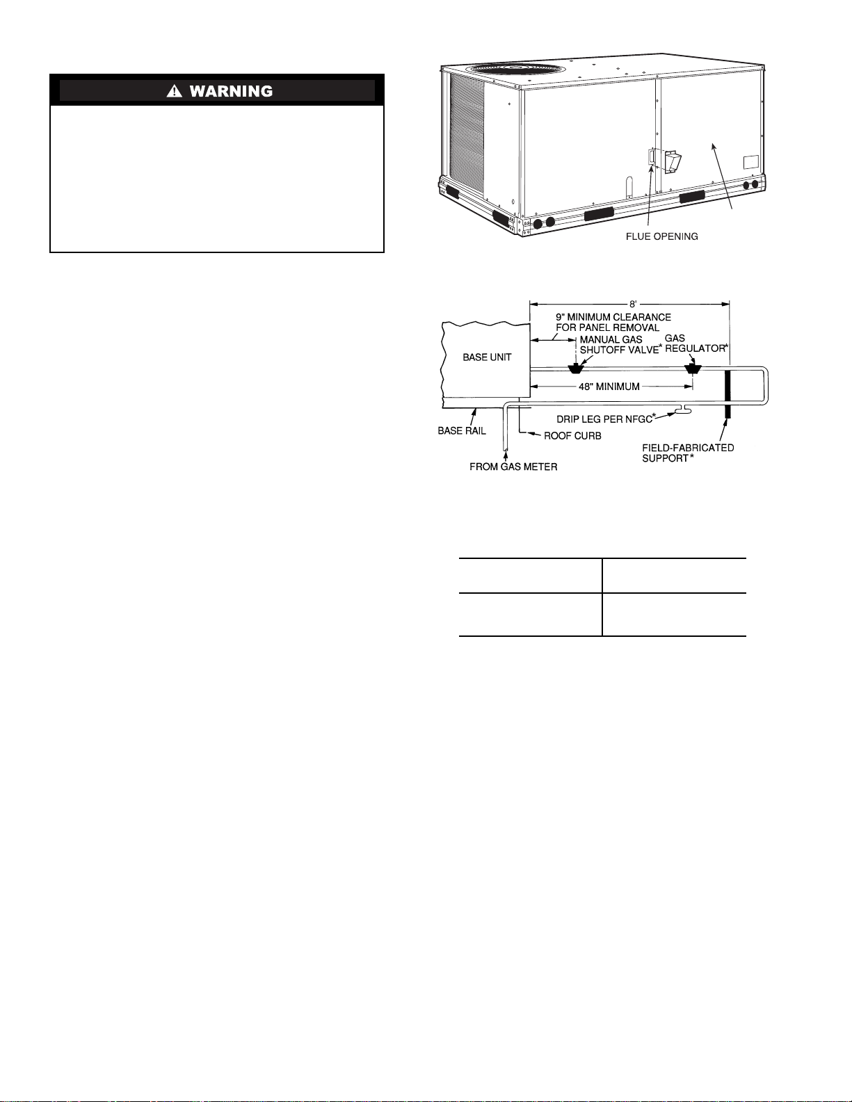
Step 5 — Install Flue Hood —
Flue hood is shipped
screwed to the basepan beside the burner compa rtment access
panel. Remove from shipping location and using screws provided, install flue hood and screen in location shown in Fig. 7.
Step 6 — Install Gas Piping —
Unit is equipped for
use with type of gas shown on nameplate. Refer to local building codes, or in the absence of local codes, to ANSI Z223.1 entitled National Fuel Gas Code. In Canada, installation must be
in accordance with the CAN1.B149.1 and CAN 1.B149.2 installation codes for gas burning appliances.
For natural gas applications, gas pressure at unit gas con-
nection must not be less than 4 in. wg or greater than
13.0 in. wg while unit is operating. On 48TF005,006,007 high
heat units, the gas pressure at unit gas connection must not be
less than 5 in. wg or greater than 13 in. wg while the unit is operating. For propane applications, the gas pressure must not
be less than 5 in. wg or greater than 13 in. wg at the unit
connection.
Size gas supply piping for 0.5 in. wg maximum pressure
drop. Do not use supply pipe smaller than unit gas connection.
Support gas piping as shown in the table in Fig. 8. For exam-
3
ple, a
/4-in. gas pipe must have one field-fabricated support
beam every 8 ft. Therefore, an 18-ft long gas pipe would have a
minimum of 2 support beams, a 48-ft long pipe would have a
minimum of 6 support beams.
See Fig. 8 for typical pipe guide and locations of external
manual main shutoff valve.
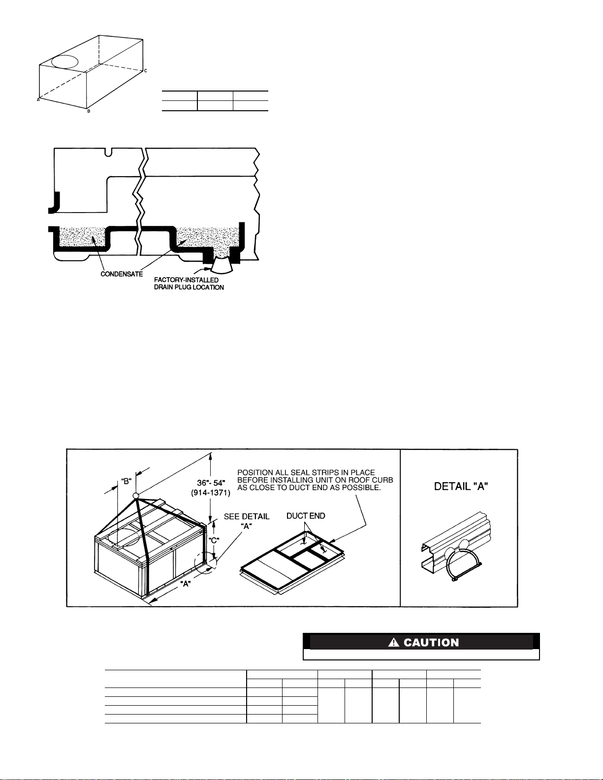
NOTES:
1. Dimensions in ( ) are in millimeters.
2. Hook rigging shackles thr ough holes in base rail, as shown in d etail “A.’
Holes in base rails are centered around the unit center of gravity. Use
wooden top skid when rigging to prevent rigging straps from damaging unit.
UNIT
48TFE,TFF,TFM,TFN004 510 231
48TFD,TFE,TFF ,TFL,TFM,TFN005 520 236
48TFD,TFE,TFF ,TFL,TFM,TFN006 540 245
48TFD,TFE,TFF007 615 279
MAX WEIGHT “A” “B” “C”
Lb Kg in. mm in. mm in. mm
Fig. 5 — Rigging Details
3. Unit weights do not include economizer. See Table 1 for economizer
weights.
All panels must be in place when rigging.
73.69 1872 37.50 953 33.35 845
4
Table 1 — Physical Data — 48TF004-007
UNIT SIZE 48TF E/F/M/N004 D/E/F/L/M/N005 D/E/F/L/M/N006 D/E/F007
NOMINAL CAPACITY (tons) 3456
OPERATING WEIGHT (lb)
Unit
Al/Al* 460 470 490 565
Al/Cu* 465 476 497 576
Cu/Cu* 468 482 505 587
Economizer
Durablade 34 34 34 34
EconoMi$er 47 47 47 47
Roof Curb† 115 115 115 115
COMPRESSOR Reciprocating
Quantity 1111
No. Cylinders (per Circuit) 2222
Oil (oz) 50 50 50 54
REFRIGERANT TYPE R-22
Expansion Device Acutrol™ Metering Device
Operating Charge (lb-oz)
Circuit 1 4-4 6-6 6-14 9-0
Circuit 2 ————
CONDENSER COIL Enhanced Copper Tubes, Aluminum Lanced Fins
Rows...Fins/in. 1...17 2...17 2...17 2...17
Total Face Area (sq ft) 8.36 8.36 10.42 10.42
CONDENSER FAN Propeller Type
Nominal Cfm 3500 4000 4000 4000
Quantity...Diameter (in.) 1...22.0 1...22.0 1...22.0 1...22.0
Motor Hp...Rpm
Watts Input (Total) 325 325 325 325
EVAPORATOR COIL Enhanced Copper Tubes, Aluminum Double-Wavy Fins
Rows...Fins/in. 2...15 2...15 3...15 4...15
Total Face Area (sq ft) 4.17 5.5 5.5 5.5
EVAPORATOR FAN Centrifugal Type
Quantity...Size (in.) Std 1...10 x 10 1...10 x 10 1...11 x 10 1...10 x 10
Type Drive Std Direct Direct Direct Belt
Nominal Cfm 1200 1600 2000 2400
Maximum Co ntinuous Bhp Std .34 .75 1.20 2.40
Motor Frame Size Std 48 48 48 56
Nominal Rpm High/Low Std 860/800 1075/970 1075/970 —
Fan Rpm Range Std — — — 1070-1460
Motor Bearing Type Ball Ball Ball Ball
Maximum Allowable Rpm 2100 2100 2100 2100
Motor Pulley Pitch Diameter Min/Max (in.) Std — — — 2.8/3.8
Nominal Motor Shaft Diameter (in.) Std
Fan Pulley Pitch Diameter (in.) Std ———4.5
Belt, Quantity...Type...Length (in.) Std — — — 1...A...40
Pulley Center Line Dis tance (in.) Std — — — 14.7-15.5
Speed Change per Full Turn of Std ———80
Movable Pulley Flange (rpm) Alt 48 70 80 —
Movable Pulley Maximum Full Turns Std ——— 5
From Closed Position Alt 555—
Factory Setting Std ——— 3
Factory Speed Setting (rpm) Std ———1225
Fan Shaft Diameter at Pulley (in.)
Alt 1...10 x 10 1...10 x 10 1...10 x 10 —
High-Static 1...10 x 10 1...10 x 10 1...11 x 10 1...10 x 10
Alt Belt Belt Belt —
High-Static Belt Belt Belt Belt
Alt 1.00 1.00 1.30/2.40** —
High-Static 2.40 2.40 2.90 2.90
Alt 48 48 56 —
High-Static 56 56 56 56
Alt 1620 1620 1725 —
High-Static 1725 1725 1725 1725
Alt 760-1000 835-1185 900-1300 —
High-Static 1075-1455 1075-1455 1300-168 5 1300-1685
Alt 1.9/2.9 1.9/2.9 2.4/3.4 —
High-Static 2.8/3.8 2.8/3.8 3.4/4.4 3.4/4.4
Alt
High-Static
Alt 4.5 4.0 4.5 —
High-Static 4.5 4.5 4.5 4.5
Alt 1...A...34 1...A...34 1...A...39 —
High-Static 1...A...39 1...A...39 1...A...40 1...A...40
Alt 10.0-12.4 10.0-12.4 14.7-15.5 —
High-Static 10.0-12.4 10.0-12.4 14.7-15.5 14.7-15.5
High-Static 65 65 60 60
High-Static 6655
Alt 333—
High-Static 3
Alt 856 975 1060 —
High-Static 1233 1233 1396 1396
LEGEND
Al — Aluminum
Bhp — Brake Horsepower
Cu — Copper
*Evaporator coil fin material/co ndenser coil fin material. Cont act your local
representative for details about coated fins.
†Weight of 14-in. roof curb.
**Single phase/three-phase.
1
/4...1100
1
/
1
/
5
/
1
5
/
1
/4...1100
1
31/
/
2
1
/
2
5
/
8
2
5
/
8
2
2
8
/
2
8
††Rollout switch lockout is manually reset by interrupting power to unit or
resetting thermostat.
|| Single- phase unit s have a single-st age gas valve. The heating in put values
are as follows:
48TFF004, 115,000 Btuh
48TFF005, 150,000 Btuh
48TFF006, 150,000 Btuh
1
/4...1100
1
/
5
/
5
/
31/
5
/
2
8
8
2
8
NOTE: High-static motor not available on single-phase units.
Scroll
1
/4...1100
5
/
—
5
/
31/
5
/
8
8
2
8
5
Table 1 — Physical Data — 48TF004-007 (cont)
UNIT SIZE 48TF E/F/M/N004 D/E/F/L/M/N005 D/E/F/L/M/N006 D/E/F007
FURNACE SECTION
Rollout Switch Cutout
Temp (F)†† 195 195 195 195
Burner Orifice Diameter
(in. ...drill size)
Natural Gas Std TFD — .113...33 .113...33 .113...33
Liquid Propane Alt TFD — .089...43 .089...43 .089...43
Thermostat Heat Anticipator
Setting (amps)
208/230 v and 575 Stage 1 .14 .14 .14 .14
460 v Stage 1 .14 .14 .14 .14
Gas Input (B tuh)|| Stage 1 TFD — 72,000 72,000 72,000
Efficiency (Steady
State) (%) 80 80 80 80
Temperature Rise Range TFD — 25-55 25-55 25-55
Manifold Pressure (in. wg)
Natural Gas Std 3.5 3.5 3.5 3.5
Liquid Propane Alt 3.5 3.5 3.5 3.5
Gas Valve Quantity 1111
Gas Valve Pressure Range
Psig 0.180-0.487 0.180-0.487 0.180-0.487 0.180-0.487
in. wg 5.0-13.5 5.0-13.5 5.0-13.5 5.0-13.5
Field Gas Connection
Size (in.)
HIGH-PRESSURE SWITCH (psig)
Standard Com p ressor 450 ± 50 500 ± 50
Internal Relief (Differential)
Cutout 428 428
Reset (Auto.) 320 320
LOSS-OF-CHARGE (LOWPRESSURE SWITCH) (psig)
Cutout
Reset (Auto.) 22 ± 7
FREEZE PROTECTION
THERMOSTAT (F)
Opens 30 ± 5
Closes 45 ± 5
OUTDOOR-AIR INLET SCREENS Cleanable
Quantity...Size (in.) 1...20 x 24 x 1
RETURN-AIR FILTERS Throwaway
Quantity...Size (in.) 2...16 x 25 x 2
Stage 2 .14 .14 .14 .14
Stage 2 .14 .14 .14 .14
Stage 2
(3-phase units)
LEGEND
Al — Aluminum
Bhp — Brake Horsepower
Cu — Copper
*Evaporator coil fin material/co ndenser coil fin material. Cont act your local
representative for details about coated fins.
†Weight of 14-in. roof curb.
**Single phase/three-phase.
TFE .113...33 .113...33 .113...33 .113...33
TFF .113...33 .129...30 .129...30 .129...30
TFL — .102...38 .102...38 —
TFM .102...38 .102...38 .102...38 —
TFN .102...38 .116...32 .116...32 —
TFE .089...43 .089...43 .089...43 .089...43
TFF .089...43 .102...38 .102...38 .102...38
TFL — .082...45 .082...45 —
TFM .082...45 .082...45 .082...45 —
TFN .082...45 .089...43 .089...43 —
TFE 72,000 115,000 115,00 0 115,000
TFF 82,000 120 ,000 120,000 120,000
TFL — 60,000 60,000 —
TFM 60,000 90,000 90,000 —
TFN 90,000 120,000 120,000 —
TFF 115,000 150,000 150,000 150,000
TFE 25-55 35-65 35-65 35-65
TFF 55-85 50-80 50-80 50-80
TFL — 20-50 20-50 —
TFM 20-50 30-60 30-60 —
TFN 30-60 40-70 40-70 —
1
/
2
1
/
2
1
/
2
1
/
2
7 ± 3
††Rollout switch lockout is manually reset by interrupting power to unit or
resetting thermostat.
|| Single-phase units have a single-stage gas valve. The heating input values
are as follows:
48TFF004, 115,000 Btuh
48TFF005, 150,000 Btuh
48TFF006, 150,000 Btuh
NOTE: High-static motor not available on single-phase units.
6
STD UNIT
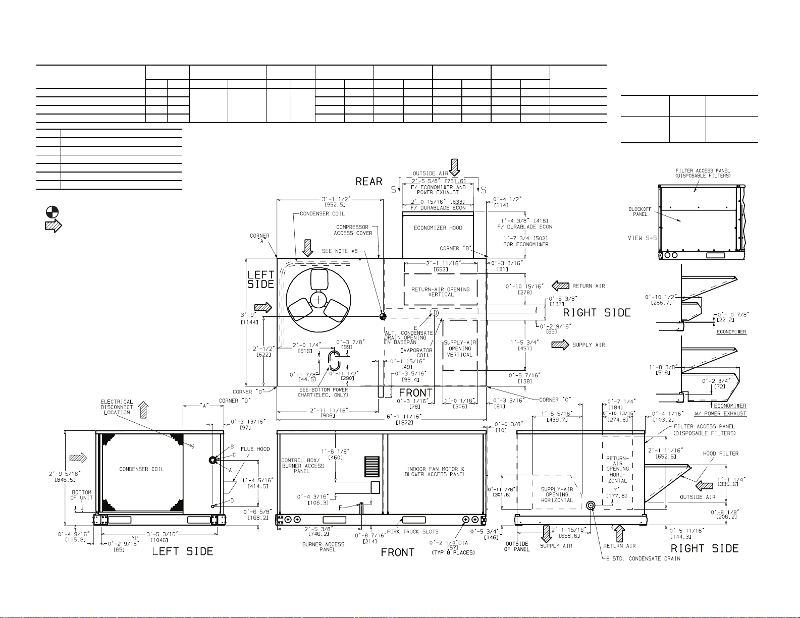
UNIT
48TFN,TFM,TFF,TFE004
48TFN,TFM,TFL,TFF,TFE,TFD005
48TFN,TFM,TFL,TFF,TFE,TFD006
48TFF,TFE,TFD007
CONNECTION SIZES
3
1
/
Dia. [35] Field Power Supply Hole
A
B
C
D
E
F
NOTES:
1. Dimen s ions in [ ] are in millimeters.
″
8
2″ Dia. [51] Power Supply Knockout
1
/
2
Dia. [64] Power Supply Knockout
″
2
7
/
Dia. [22] Field Control Wiring Hole
″
8
3
/
-14 NPT Condensate Drain
″
4
1
/
-14 NPT Gas Connection
″
2
WEIGHT
Lbs Kg Lbs Kg Lbs Kg Lbs Kg Lbs Kg Lbs Kg Lbs Kg
460 209
470 213 142 64.4 106 48.1 162 73.5 60 27.2 1′-10
490 222 150 68.0 115 52.2 160 72.6 65 29.5 1′-0
565 256 165 74.8 136 61.7 200 90.7 64 29.0 1′-0
2. Center of Gravity.
3. Direction of Airflow.
4. On vertical discharge units, ductwork to be attached to accessory
roof curb only. For horizontal discharge units, field-supplied flanges
should be attached to horizontal discharge openings, and all ductwork should be attached to the flanges.
5. Minimum clearance (local codes or jurisdiction may prevail):
a. Between unit, flue side and combustible surfaces, 36 inches.
b. Bottom of unit to combustible surfaces (when not using curb)
1 inch. Bottom of base rail to combustible surfaces (when not
using curb) 0 inches.
c. C ondenser coil for proper airflow, 36 in. one side, 12 in. the other.
The side getting the greater clearance is optional.
d. Overhead, 60 in. to assure proper condenser fan operation.
e. Between units, control box side, 42 in. per NEC (National Electri-
7
cal Code).
f. Between unit and ungrounded surfaces, control box side, 36 in.
per NEC.
g. Between unit and block or concrete walls and other grounded sur-
faces, control box side, 42 in. per NEC.
h. Horizontal supply and return end, 0 inches.
6. With the exception of the clearance for the condenser coil and combustion side as stated in Note 5a, b, and c, a removable fence or barricade requires no clearance.
7. Units may be installed on combustible floors made from wood or
Class A, B, or C roof covering material if set on base rail.
8. The vertical center of gravity is 1′-6″ [457] up from the bottom of the
base rail.
DURABLADE
ECONOMIZER WEIGHT
ECONOMI$ER
WEIGHT
34 15.4 47 21.3
(A)
CORNER WEIGHT
(B)
CORNER WEIGHT
(C)
CORNER WEIGHT
(D)
CORNER WEIGHT
140 63.5 105 47.6 159 72.1 56 25.4 1′-10
“A”
PANEL
LENGTH
3
/
[568.0]
″
8
3
/
[568.0]
″
8
3
/
[315.0]
″
8
3
/
[315.0]
″
8
BOTTOM POWER CHART,
THESE HOLES REQ’D FOR USE
WITH ACCESSORY PACKAGES —
CRBTMPWR001A00, 3A00 (
THREADED
CONDUIT
SIZE
1
″
/
2
3
″
/
4
1
″
FPT
/
2
WIRE
USE
24 V
Power 1
Gas 1
1
/2″, 3/4″)
REQ’D HOLE
SIZES
(Max.)
7
/
″
8
1
/
8
1
/
4
[22.2]
[28.4]
″
[31.8]
″
Fig. 6 — Base Unit Dimensions
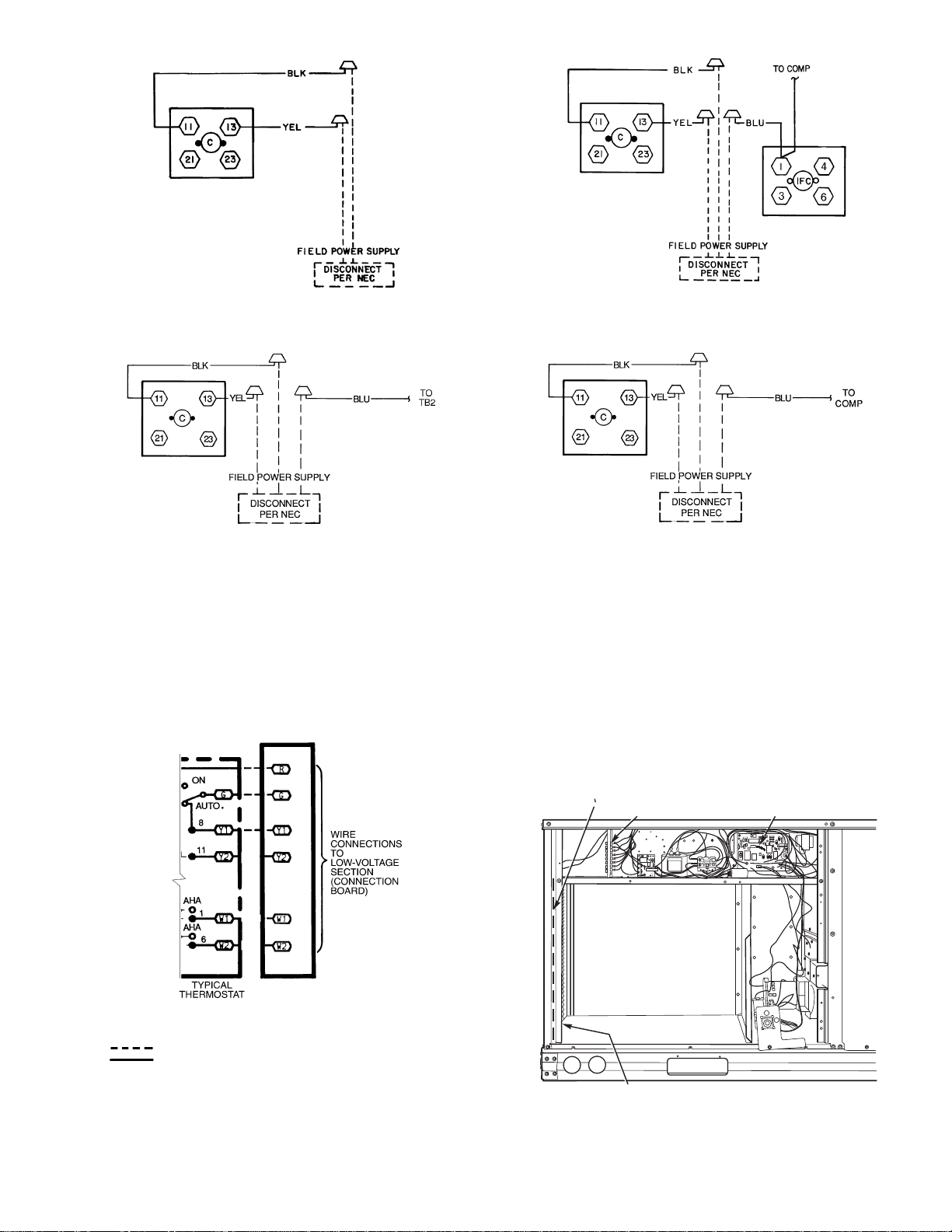
Step 7 — Make Electrical Connections
BLOWER
ACCESS
PANEL
LEGEND
NFGC —
National Fuel Gas Code
*Field supplied.
NOTE: Follow all local codes.
SPACING OF SUPPORTS
Fig. 8 — Gas Piping Guide (With Accessory
Thru-the-Curb Service Connections)
STEEL PIPE
NOMINAL DIAMETER
(in.)
X
DIMENSIONS
(feet)
1
/
2
6
3
/4 or 1
8
11/4 or larger
10
Fig. 7 — Flue Hood Details
Unit cabinet must have an uninterrupted, unbroken electrical ground to minimize the possibility of personal injury if
an electrical fault should occur. This ground may consist of
electrical wire connected to unit ground lug in control compartment, or conduit approved for electrical ground when
installed in accordance with NEC (National Electrical
Code), ANSI/NFPA, latest edition, and local electrical
codes. Do not use gas piping as an electrical ground. Fail-
ure to follow this warning could result in the installer being
liable for personal injury of others.
FIELD POWER SUPPLY — All units except 208/230-v
units are factory wired for the voltage shown on the nameplate.
If the 208/230-v unit is to be connected to a 208-v power supply, the transformer must be rewired by moving the black wire
with the
nection and moving to the 200-volt
primary side of the transformer.
tails are provided for field wire connections. Use factorysupplied splices or UL (Underwriters’ Laboratories) approved
copper/aluminum connector .
requirements.
Install field wiring as follows:
within voltage range indicated on unit nameplate (see Table 2).
On 3-phase units, voltages between phases must be balanced
within 2% and the current within 10%. Use the formula shown
in the legend for Table 2, Note 2 to determine the percent of
voltage imbalance. Operation on improper line voltage or excessive phase imbalance constitutes abuse and may cause damage to electrical components. Such operation would invalidate
any applicable Carrier warranty.
FIELD CO NTROL WIRING — Install a Carrier-approved
accessory thermostat assembly according to installation
instructions included with the acc essory. Locate thermostat assembly on a solid wall in the conditioned space to sense ave rage temperature in accordanc e with thermostat ins tallation instructions. Connect thermostat wires to terminal board.
wire from subbase terminals through connector on unit to lowvoltage connections (shown in Fig. 10).
NOTE: For wire runs up 50 ft, use no. 18 AWG (American
Wire Gage) insulated wire (35 C minimum). For 50 to 75 ft,
use no. 16 AWG insulated wire (35 C minimum). For over
75 ft, use no. 14 AWG insulated wire (35 C minimum). All
wire larger than no. 18 AWG cannot be directly connected to
1
/4-in. female space connector from the 230-volt con-
1
/4-in. male terminal on the
Refer to unit label diagram for additional information. Pig-
When installing units, provide a disconnect per the NEC.
All field wiring must comply with NEC and local
1. Install conduit through side panel openings. For units
without electric heat, install conduit between disconnect
and control box.
2. Install power lines to terminal connections as shown in
Fig. 9.
Voltage to compressor terminals during operation must be
Route thermostat cable or equivalent single leads of colored
the thermostat and will require a junction box and splice at the
thermostat.
Pass the control wires through the hole provided in the corner post; then feed wires through the raceway built into the
corner post to the 24-v barrier located on the left side of the
control box. See Fig. 11. The raceway provides the UL required clearance between high- and low-voltage wiring.
HEAT ANTICIPATOR SETTINGS — Set heat anticipator
settings at .14 amp for the first stage and .14 amp for secondstage heating, when available.
8
RACEWAY LOW VOLTAGE
CONNECTIONS
INTEGRATED GAS UNIT
CONTROLLER (IGC)
HOLE IN END PANEL (HIDDEN)
208/230-1-60
208/230-3-60
460-3-60
(SIZE 007 ONLY)
LEGEND
C—
COMP —
NEC —
TB —
575-3-60
(SIZE 007 ONLY)
Contactor
Compressor
National Electrical Code
Terminal Block
208/230-3-60
575-3-60, 460-3-60
(SIZES 004-006)
Fig. 9 — Power Wiring Connections
AHA —
NOTES:
1. Connect Y2 when unit is equipped with an economizer.
2. Connect W2 when unit is equipped with two stages of heat.
Adjustable Heat Anticipator
Field Wiring
Factory Wiring
Fig. 10 — Low-Voltage Connections
LEGEND
Fig. 11 — Field Control Wiring Raceway
9
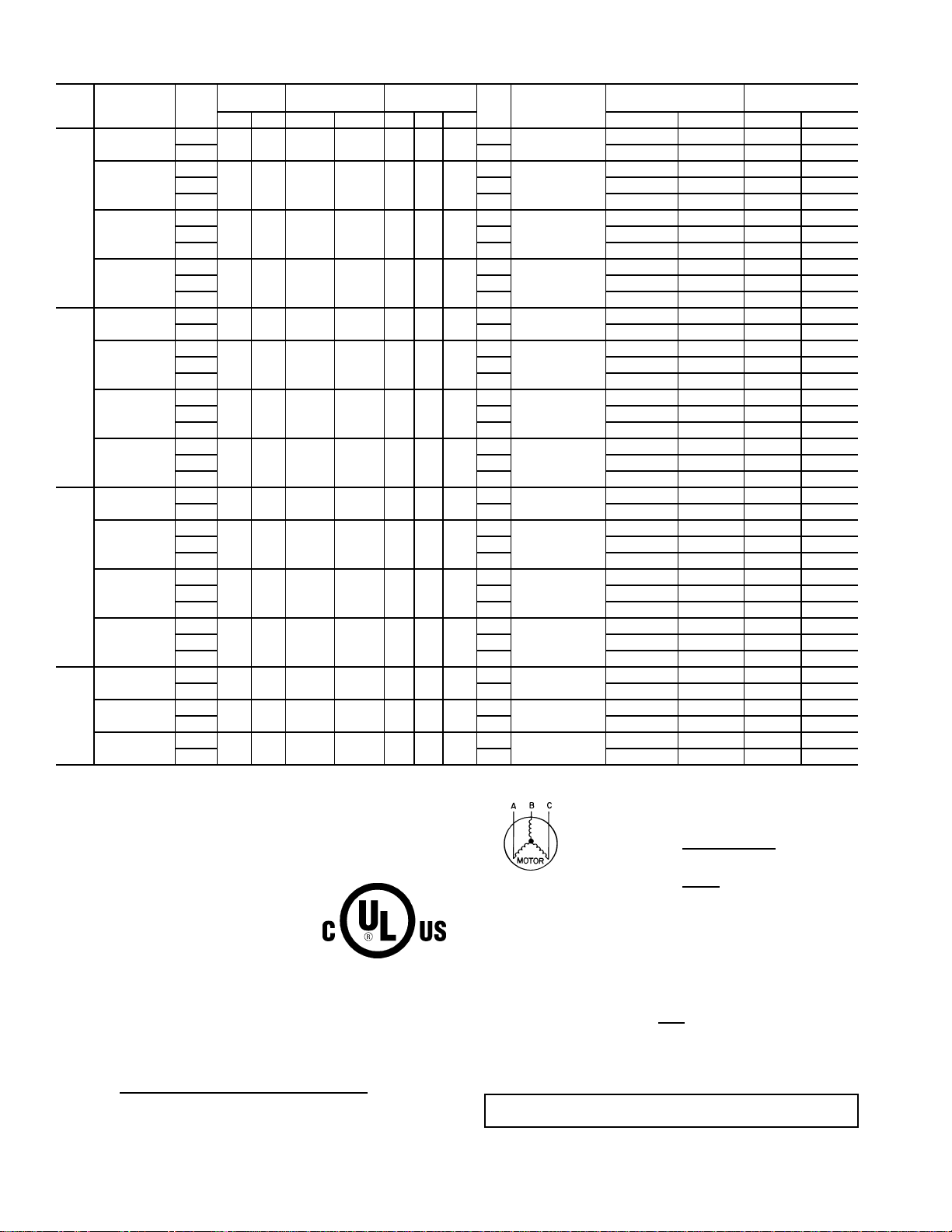
Table 2 — Electrical Data
UNIT
48TF
NOMINAL
V-Ph-Hz
208/230-1-60
VOLTAGE
IFM
TYPE
RANGE
Min Max RLA LRA Qty Hp FLA MCA MOCP† FLA LRA
Std
187 254 16.2 96.0 1
Alt 4.9 26.6/26.6 35/35 26/26 111/111
COMPRESSOR
(ea)
Std
208/230-3-60
187 254 10.2 75.0 1
Alt 4.9 19.1/19.1 25/25 19/19 90/90
High 5.2 19.4/19.4 25/25 19/19 109/109
004
460-3-60
Std
Alt 2.1 8.4 15 8 48/48
414 508 4.4 40.0 1
High 2.6 8.9 15 9 57/57
Std
575-3-60
Alt 2.1 6.9 15 8 37
518 632 3.7 31.0 1
High 2.6 7.3 15 7 45
208/230-1-60
Std
187 254 23.3 118.0 1
Alt 4.9 35.4/35.4 45/45 34/34 133/133
Std
208/230-3-60
187 254 15.4 90.0 1
Alt 4.9 25.6/25.6 30/30 25/25 105/105
High 5.2 25.9/25.9 30/30 25/25 124/124
005
460-3-60
Std
Alt 2.1 13.3 20 13 53
414 508 8.3 45.0 1
High 2.6 13.8 20 13 62
Std
575-3-60
Alt 2.1 10.3 15 11 42
518 632 6.4 36.0 1
High 2.6 10.7 15 10 50
208/230-1-60
Std
187 254 28.8 147 1
Alt 6.6 44.0/44.0 60/60 42/42 184/184
Std
208/230-3-60
187 254 16.3 114 1
Alt 5.2 26.6/26.6 35/35 26/26 148/148
High 7.5 28.9/28.9 35/35 29/29 174/174
006
460-3-60
Std
Alt 2.6 12.7 15 12 81
414 508 7.4 64 1
High 3.4 13.5 20 13 94
Std
575-3-60
Alt 3.0 10.5 15 10 66
518 632 6.2 62 1
High 3.4 12.6 15 11 76
Std
187 254 23.6 146 1
High 7.5 32.5/32.5 40/40 32/32 205/205
Std
414 508 10.6 73 1
High 3.4 16.1 20 16 103
Std
518 632 8.5 58.4 1
High 3.4 12.9 20 14 82
007
208/230-3-60
460-3-60
575-3-60
LEGEND
FLA — Full Load Amps
HACR — Heating, Air Conditioning and Refrigeration
IFM — Indoor (Evaporator) Fan Motor
LRA — Locked Rotor Amps
MCA — Minimum Circuit Amps
MOCP — Maximum Overcurrent Protection
NEC — National Electrical Code
OFM — Outdoor (Condenser) Fan Motor
RLA — Rated Load Amps
*Used to determine minimum disconnect per NEC.
†Fuse or HACR circuit breaker.
NOTES:
1. In compliance with NEC requirements for multimotor and combination
load equipment (refer to NEC Articles 430 and 440), the overcurrent
protective device for th e uni t sha ll be f use o r HA CR br eak er. Canadian
units may be fuse or circuit breaker.
2.
Unbalanced 3-Phase Supply Voltage
Never operate a motor where a phase imbalance in supply voltage is
greater than 2%.
of voltage imbalance.
Use the following formula to determine the percent
% Voltage Imbalance
= 100 x
max voltage dev i ation from average voltage
average voltage
OFM
(ea)
1
/41.4
1
/41.4
1
/40.8
1
/40.8
1
/41.4
1
/41.4
1
/40.8
1
/40.8
1
/41.4
1
/41.4
1
/40.8
1
/40.8
1
/41.4
1
/40.6
1
/40.6
IFM
FLA
3.5
3.5
COMBUSTION
FAN MOTOR
FLA
.6
POWER
SUPPLY
24.5/24.5 30/30 23/23 106/106
17.7/17.7 25/25 17/17 85/85
DISCONNECT
SIZE*
.6
1.3
7.6 15 7 48/48
.3
1.3
6.3 15 7 35
.3
3.5
3.5
.6
34.0/34.0 40/40 32/32 129/129
24.2/24.2 30/30 23/23 101/101
.6
1.8
13.0 20 13 51
.3
1.8
10.1 15 10 41
.3
5.9
5.9
.6
43.3/43.3 60/60 42/42 161/161
27.3/27.3 35/35 29/29 128/128
.6
3.1
13.2 20 13 72
.3
3.1
10.9 15 11 58
.3
5.2
2.6
2.6
.6
.3
.3
30.2/30.2 35/35 29/29 180/180
15.4 20 15 90
12.3 15 13 72
Example: Supply voltage is 460-3-60.
AB = 452 v
BC = 464 v
AC = 455 v
Average Voltage =
Determi ne maximum deviation from average volt ag e.
(AB) 457 – 452 = 5 v
(BC) 464 – 457 = 7 v
(AC) 457 – 455 = 2 v
452 + 464 + 455
1371
=
3
= 457
3
Maximum deviation is 7 v.
Determine percent of voltage imbalance.
% Voltage Imbalance = 100 x
7
457
= 1.53%
This amount of phase imbalance is satis f act ory as it is below t he maximum allowable 2%.
IMPORTANT:
than 2%, contact your loca l electric utility company immediately.
If the supply voltage phase imbalance is more
10
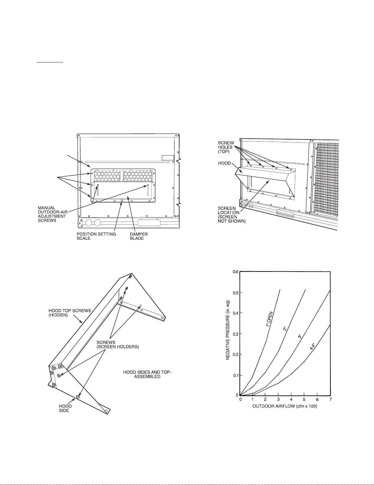
Step 8 — Make Outdoor-Air Adjustments and
Fig. 14 — Outdoor-Air Damper with
Hood Att ached
Fig. 15 — Position Setting
Install Outdoor-Air Hood
MANUAL OUTDOOR-AIR DAMPER — The outdoor-air
hood and screen are attached to the basepan at the bottom of
the unit for shipping.
Assembly:
1. Determine quantity of ventilation required for building.
Record amount for use in Step 8.
2. Remove and save outdoor air opening panel and screws.
See Fig. 12.
3. Separate hood and screen from basepan by removing the
4 screws securing them. Save all screws.
4. Replace evaporator coil access panel.
OUTDOOR
AIR OPENING
PANEL
3 SCREWS
(SIDE)
5. Place hood on front of outdoor air opening panel. See
Fig. 13 for hood details. Secure top of hood with the
4 screws removed in Step 3. See Fig. 14.
6. Remove and save 6 screws (3 on each side) from sides of
the manual outdoor-air damper.
7. Align screw holes on hood with screw holes on side of
manual outdoor-air damper. See Fig. 13 and 14. Secure
hood with 6 screws from Step 6.
8. Adjust minimum position setting of the damper blade by
adjusting the manual outdoor-air adjustment screws on
the front of the damper blade. See Fig. 12. Slide blade
vertically until it is in the appropriate position determined
by Fig. 15. Tighten screws.
9. Remove and save screws currently on sides of hood. Insert screen. Secure screen to hood using the screws. See
Fig. 14.
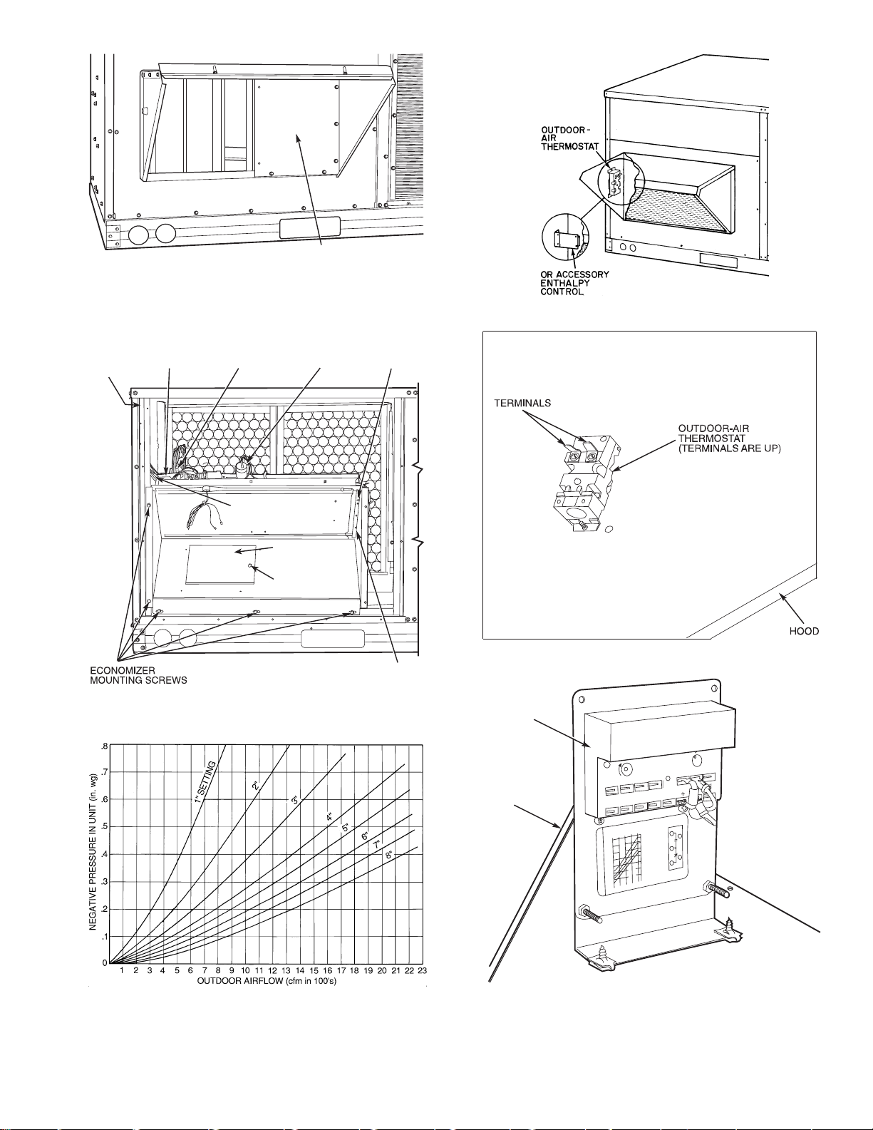
Fig. 12 — Damper Panel with Manual Outdoor-Air
Damper Installed
Fig. 13 — Outdoor-Air Hood Details
11
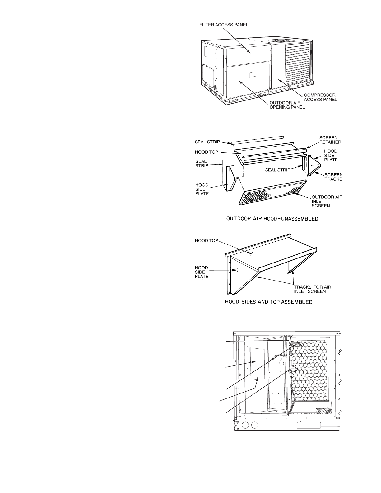
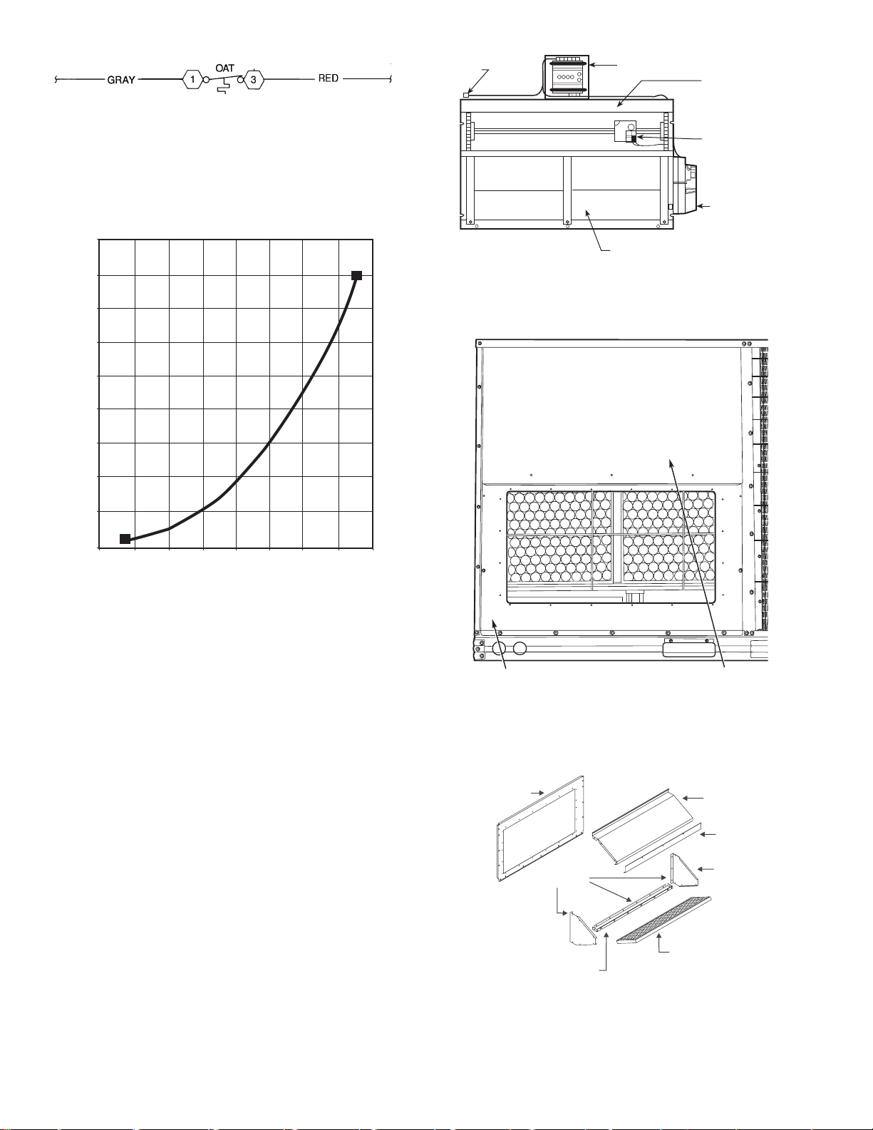
OPTIONAL DURABLADE ECONOMIZER — The op-
Fig. 16 — Typical Access Panel Locations
Fig. 17 — Outdoor-Air Hood Details
Fig. 18 — Horizontal Durablade Economizer
Installation
tional economizer hood assembly is packaged and shipped in
the filter section. Damper blades and control boards are installed at the factory and the economizer is shipped in the vertical discharge position.
NOTE: Horizontal discharge block-off plate is shipped with
the air hood package. If unit is to be used for vertical discharge
application, discard this plate.
Assembly:
1. Determine if ventilation air is required in building. If so,
determine minimum amount to be supplied by each unit
and record quantity of ventilation air needed for use in
Step 6.
2. Remove filter access panel by raising panel and swinging
panel outward. Panel is now disengaged from track and
can be removed. No tools are required to remove filter
access panel. Remove outdoor-air opening panel. Save
panels and screws. See Fig. 16. Remove optional
outdoor-air damper hood package from filter section.
3. Assemble outdoor-air hood top and side plates as shown
in Fig. 17. Install seal strips on hood top and sides. Put
aside screen retainer and screws for later assembly. Do
not attach hood to unit at this time.
4. To convert to horizontal discharge application:
a. Rotate economizer 90 degrees until the
economizer motor faces the condenser section
(see Fig. 18).
b. Rotate the barometric relief damper hinge
90 degrees. Barometric relief damper should open
vertically to operate properly.
c. Install horizontal discharge block-off plate over
the opening on the access panel. (Block-off plate
MUST be installed before installing hood assembly.) See Fig. 19.
5. Insert economizer plug into economizer harness. Remove
tape from barometric relief damper. See Fig. 20.
6. If ventilation air is not required, proceed to St ep 7. If ventilation air is required, determine minimum position setting for required airflow. See Fig. 21. Adjust minimum
position setting by adjusting the screws on the position
setting bracket. Slide bracket until the top screw is in the
position determined by Fig. 21. Tighten screws.
7. Remove tape from outdoor-air thermostat (OAT). Fasten
OAT to inside of hood using screws and speed c lips provided. See Fig. 22. Make sure OAT terminals are positioned up.
8. Replace outdoor-air opening panel using screws from
Step 2. Replace filter a ccess panel. Ensure the filter ac cess panel slides along the tracks and is securely engaged.
9. Fasten hood top and side plate assembly (Fig. 17) to
outdoor-air opening panel with screws provided.
10. Place knob supplied with economizer on OAT. See
Fig. 22. Set for 3° F below indoor room thermostat setting. If accessory enthalpy control (EC) is used in place of
OAT, see instructions shipped with EC for installation
and adjustment. See Fig. 22.
11. Connect OAT per Fig. 23.
12. Slide outdoor-air inlet screen into screen track on hood
side plate. While holding screen in place, fasten screen retainer to hood using screws provided.
NOTE: Refer to Fig. 24 for economizer barometric relief
damper characteristics.
ECONOMIZER
CONTROL
BOARD
BAROMETRIC
RELIEF
DAMPER
ECONOMIZER
PLUG
SHIPPING
SCREW
ECONOMIZER
MOTOR
12
BLOCK-OFF PLATE
MINIMUM
POSITION
OPEN
3
1
T
P
P1
T1
4
2
5
S
S
O
D
C
TR
B
REV.B
198818A
%
H
U
M
I
D
I
T
Y
90
70
60
30
10
D
C
B
A
60
65
70
75
55
50
85
80
DAMPER
DAMPER
CLOSED
OPEN
OUTDOOR TEMP
.
°
F
REV
.
97-3672
CW–SETPOINTS–CCW
CONT
A
CTS SHO
WN IN HIGH ENTHALPY
RUSH
AT 24V
AC
3 mA
MIN. A
T 1
1 VDC
CONT
ACT RA
TINGS: 1.5A
RUN, 3.5A IN
OR UNPOWERED ST
A
TE
1
2
3
TR
TR1
24V
AC
ENTHALPY CONTROL
ENTHALPY
CONTROL
HOOD
Fig. 22 — Outdoor-Air Thermostat/
Enthalpy Control Installation
Fig. 19 — Horizontal Discharge Block-Off Plate
U-SHAPED
HOLE
(NOT
SHOWN)
ECONOMIZER
CONTROL
BOARD
ECONOMIZER
PLUG
WIRING
HARNESS
BAROMETRIC
RELIEF DAMPER
SHIPPING
SCREW
ECONOMIZER
MOTOR
POSITION SETTING
BRACKET
TOP
SCREW
Fig. 20 — Durablade Economizer Installed in Unit
EXAMPLE:
Given —Negative Pressure. . . . . . . . . . . . . . . . . . . . . . .0.2 in. wg
Determine — Setting = 5 in.
Outdoor Air . . . . . . . . . . . . . . . . . . . . . . . . . . . . . 900 cfm
Fig. 21 — Durablade Economizer
Minimum Position Setting
13
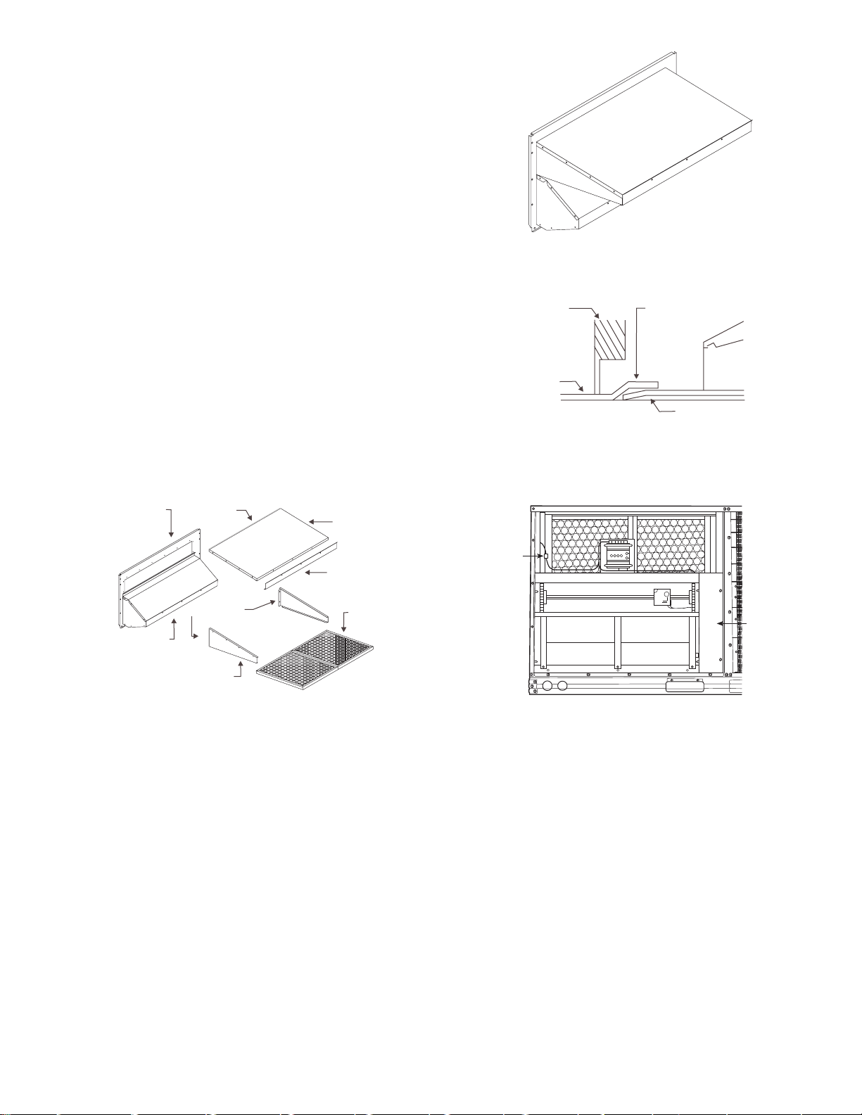
OUTDOOR AIR
OPENING PANEL
SEAL STRIP
EXHAUST AIR SCREEN
EXHAUST AIR
HOOD TOP
SCREEN
RETAINER
EXHAUST AIR
HOOD SIDES
EXHAUST AIR
BOTTOM BRACKET
Fig. 26 — Typical Access Panel Locations
Fig. 27 — Exhaust Air Hood Assembly
LEGEND
Outdoor-Air Thermostat
OAT —
NOTE: See unit wiring diagram for details.
Fig. 23 — Wiring Connections for
Outdoor-Air Thermostat
ECONOMI$ER
PLUG
CONTROLLER
GEAR-DRIVEN
DAMPER
OUTDOOR AIR
TEMPERATURE
SENSOR
ACTUATOR
0.90
0.80
0.70
0.60
0.50
0.40
0.30
PRESSURE DROP (in. wg)
0.20
0.10
0.00
200 300 400
100
CFM
Fig. 24 — Durablade Economizer
Barometric Relief Damper Characteristics
OPTIONAL ECONOMI$ER — See Fig. 25 for EconoMi$er
component locations.
1. To remove the existing unit filter access panel, raise the
panel and swing the bottom outward. The panel is now
disengaged from the track and can be removed. Remove
the indoor coil access panel and discard. See Fig. 26.
If installing an optional Power Exhaust Assembly, refer to
the EconoMi$er Power Exhaust Installation Instructions.
Controller should be mounted in vertical position as
shown in Fig. 25.
2. Assemble the hood assembly as follows:
Remove the EconoMi$er hood from its packaging. Re-
move shipping brackets holding hood package to
EconoMi$er. Locate the outdoor-air opening panel. See
Fig. 27. Remove hood assembly shipping brackets located on the back (sloped) side of the EconoMi$er assembly.
These brackets are used to retain the hood assembly during shipping only.
3. Installs the
side panels and the bottom bracket. Assemble the exhaust
1
/8 x 3/4-in. seal strip on the exhaust air hood
air hood to the outdoor-air opening panel as shown in
Fig. 27, using the screws provided. Do not attach hood
assembly to unit at this time.
4. Install the
top and side panels. Assemble the outdoor-air hood to the
outdoor-air opening panel as shown in Fig. 28, using the
screws provided. Do not attach hood assembly to the uni t
1
/8 x 3/4-in. seal strip on the outdoor-air hood
at this time.
500 600
700
800
BAROMETRIC RELIEF DAMPERS
Fig. 25 — EconoMi$er Component Locations
OUTDOOR-AIR
OPENING PANEL
FILTER ACCESS
PANEL
14
5. Slide the outdoor-air inlet screens into the screen track on
ECONOMI$ER
ECONOMI$ER REAR
FLANGE
UNIT BASE
UNIT FILTER
RACK
ECONOMI$ER CLIP
HVAC UNIT
WIRING
HARNESS
OUTDOOR
AIR
BLOCK-OFF
PLATE
Fig. 29 — Completed Hood Assembly
Fig. 30 — Rear EconoMi$er Flange Installation
Fig. 31 — EconoMi$er Installed
the hood side panels. While holding the screens in place,
fasten the screen retainer to the hood using the screws
provided. Repeat the process for the barometric exhaust
air screen. Do not attach completed (Fig. 29) hood as-
sembly to unit at this time .
6. Slide the EconoMi$er assembly into the rooftop uni t. S ee
Fig. 30 and 31.
NOTE: Be sure to engage rear EconoMi$er flange under
tabs in return-air opening of the unit base. See Fig. 30.
7. Install the outdoor-air block-off plate, then secure the
EconoMi$er with the screws provided. See Fig. 31.
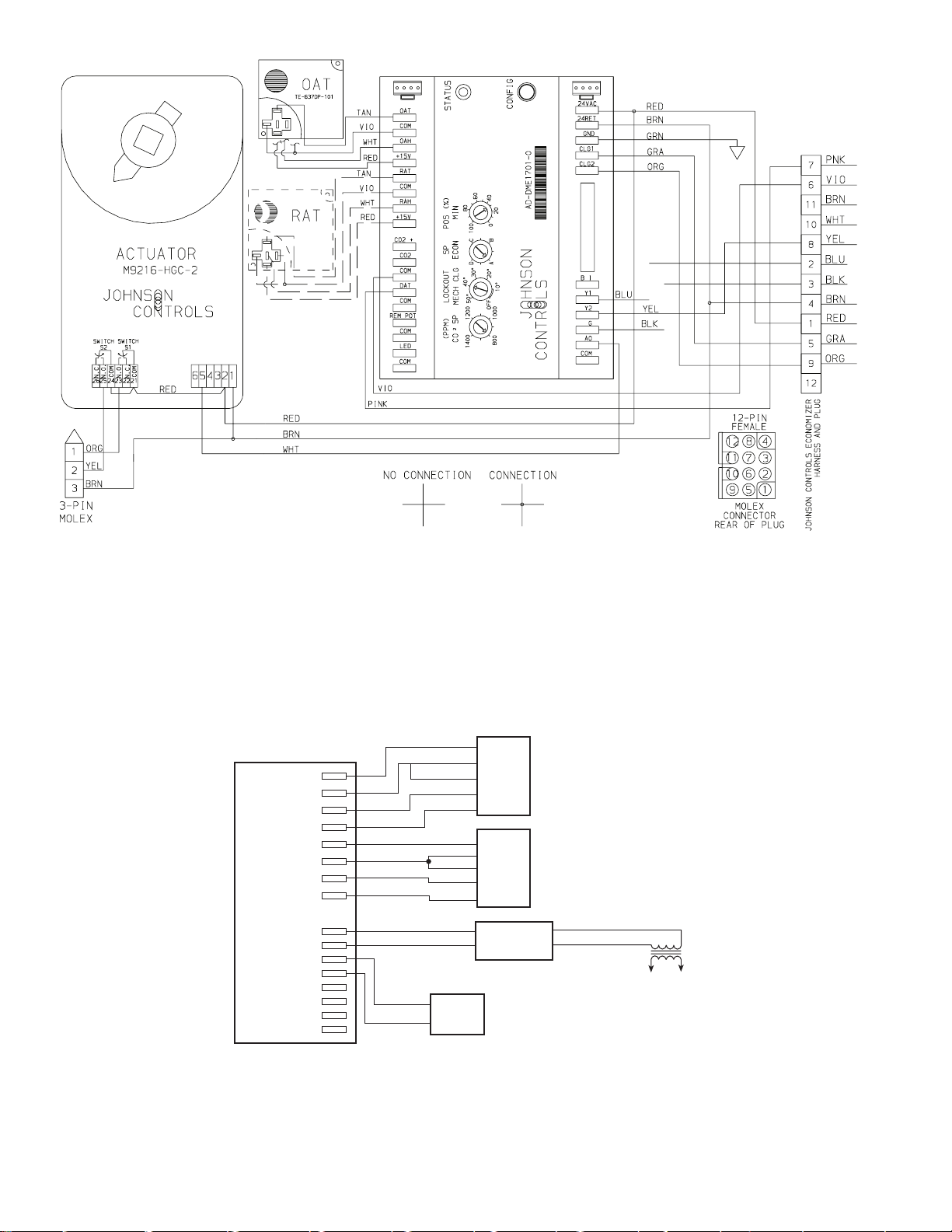
8. Remove and discard the 12-pin jumper pl ug from the unit
wiring harness located in the upper left corner and insert
the EconoMi$er plug into the unit wiring harness. Refer
to wiring diagram Fig. 32 and 33. Also refer to Fig. 34 if
installing an accessory power exhaust.
9. Install the complete hood assembly on the unit and secure
using the screws provided.
10. Remove the indoor fan motor access panel. See Fig. 35.
11. Mount the supply-air temperature sensor to the lower left
portion of the indoor blower housing with the two (2)
screws provided (see Fig. 36). Connect the violet and
pink wires to the corresponding connections on the
supply-air temperature sensor. Replace the indoor fan
motor access panel.
OUTDOOR AIR
OPENING
PANEL
ASSEMBLED
EXHAUST HOOD
SEAL STRIP
SEAL STRIP
OUTDOOR AIR
HOOD SIDES
Fig. 28 — Outdoor-Air Hood Assembly
OUTDOOR AIR
HOOD TOP
SCREEN
RETAINER
OUTDOOR AIR
INLET
SCREENS
15
OAT —
RAT —
LEGEND
Outdoor-Air Tem perature
Return-Air T emper ature
Fig. 32 — EconoMi$er Wiring
ECONOMI$ER
CONTROLLER
OAT
COM
OAH
-15 V
RAT
COM
RAH
+15 V
(+)
CO
2
COM
CO
2
DAT
COM
REM POT
COM
LED
COM
BROWN
VIOLET
WHITE
RED
BROWN
VIOLET
WHITE
RED
SUPPLY AIR
TEMPERATURE SENSOR
PINK
VIOLET
TEMP
TEMP
TEMP
TEMP
COM
OUT
PWR
TEMP
TEMP
COM
OUT
PWR
CO
SENSOR
2
V+
COM VAC
OUTDOOR
AIR
SENSOR
RETURN
AIR
SENSOR
24
Fig. 33 — EconoMi$er Sensor Wiring
16
 Loading...