


48SS-3SB
48SS018, 024, 030, 036, 042, 048 & 060
STANDARD-EFFICIENCY
COMBINATION GAS HEATING/
ELECTRIC COOLING UNITS
— PERFORMANCE DATA
— CERTIFIED DIMENSION PRINT
— CERTIFIED ROOF CURB
DIMENSION PRINT
R 1997 Carrier Corporation • Syracuse, New York 13221
Form 48SS-3SB Supersedes 48SS-2SB Printed in U.S.A. 5-97 Catalog No. 514-847
Date: Supersedes:
48SS018, 024, 030, 036, 042, 048 & 060
STANDARD-EFFICIENCY
COMBINATION GAS HEATING/
ELECTRIC COOLING UNITS
48SS
JOB DATA: LOCATION:
BUYER: BUYER P.O. # CARRIER #
UNIT NUMBER: MODEL NUMBER:
PERFORMANCE DATA CERTIFIED BY: DATE:
DESCRIPTION
48SS units are standard-efficiency, one-piece gas heating electric cooling units,
pre-wired and pre-charged at the factory.
48SS units are convertible discharge units that can be used for either horizontal or down discharge installations.
ARI 210 ARI 270
FEATURES
Standard one-year warranty.
Five-year Extended Protection Plan for the compressor.
Ten-year non-prorated warranty on heat exchanger.
Units are ‘‘Rated in accordance with ARI Standard No. 270 and
210/240.’’
Standard unit as factory assembled is design certified and listed by
UL and CSA.
Low temperature cooling operation standard to 40 F (4 C).
Hermetic compressor with internal linebreak and overload protec-
tion, self lubricating. Scroll compressors on 4 and 5 ton sizes.
Crankcase heater is standard on 024-042 3-phase units. (Not re-
quired on 018, 048 and 060 units.)
Indoor and outdoor coils constructed of aluminum fins mechan-
ically bonded to seamless copper tubes.
48SS units have single-stage cooling and heating.
Foil-faced cleanable insulation.
Sloped non-corrosive condensate drain pan.
Single-point gas connection.
Alternate electrical connections on opposite sides of unit.
Disconnect in accordance with NEC, must be field-supplied and
installed.
Multi-speed, direct drive indoor fan motor.
Weatherized cabinets. Heavy duty phosphated zinc-coated pre-
painted steel. Capable of withstanding 500-hour salt spray.
24-volt control circuit.
Heating controls include a direct spark ignition with flame
rectification. Fan switch, overtemperature switch, and flame rollout switch also included.
Induced-draft with hall effect sensor (to prove proper inducer draft
motor operation).
Alumaguard™ coated ‘‘Super-S’’ four-pass heat exchanger.
Integrated gas control board provides anti-cycle protection for gas
heat operation.
Base rail standard on all 3-phase units.
Rev.:
-3SB
PERFORMANCE DATA
Operating Weight lb (unit); lb (curb)
COOLING
Net Total Capacity
Net Sensible Capacity
Compressor Power Input
kW @ °F
Btuh
Btuh
Outdoor-Air Temperature
Indoor Entering Air db
°F wb °F
SEER/EER
ELECTRICAL DATA
Power Supply to Unit Volts Phase Hz.
Minimum Circuit Amps
ACCESSORIES AND OPTIONS
FACTORY-INSTALLED OPTIONS
M Commercial Grade Base Rail
M Dedicated Downshot/Base Rail
FIELD-INSTALLED ACCESSORIES
M 30% Open Manual Fresh Air Damper
M Roof Curb:
M 89 Height
M 119 Height
M 149 Height
M One-in. Filter Rack
M Crankcase Heater — Single Phase Only
(Required with 0° Low Ambient)
CFM Ext. Static Pressure in. wg
Indoor Fan Motor
Hp Rpm Bhp
HEATING
Input
Output
AFUE
%
Maximum Overcurrent Protection
FIELD-INSTALLED ACCESSORIES (cont)
M Programmable Electronic Thermostat
M Thermostat and Subbase
M 0° Low Ambient
M Time Guardt II
M L.P. Conversion Kit
M Controls Upgrade Kit (High and
Low-Pressure Switch)
M External Condensate Trap
M Natural Gas High-Altitude Kit (2000-5000 ft
Above Sea Level)
Btuh
Btuh
2
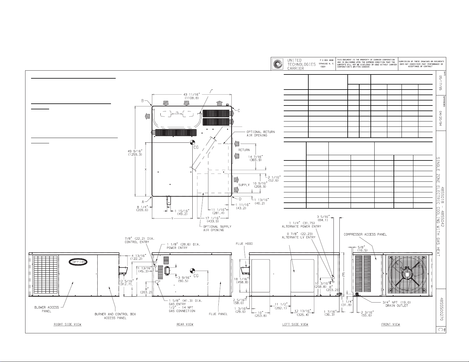
CERTIFIED DIMENSION PRINT
REQ’D CLEARANCES FOR SERVICING — in. (mm)
Duct Panel ........................0
Unit Top .....................36(914.4)
Side Opposite Ducts ..............36(914.4)
Compressor Access ..............36(914.4)
(Except for NEC requirements)
REQ’D CLEARANCES TO COMBUSTIBLE MAT’L
— in. (mm)
Maximum Extension of Overhangs ......48(1219.2)
Unit Top .....................14(355.6)
Duct Side of Unit .................2(50.8)
Side Opposite Ducts ..............14(355.6)
Bottom of Unit ......................0
Flue Panel ...................36(914.4)
NEC (National Electrical Code) REQ’D CLEARANCES
— in. (mm)
Between Units, Control Box Side .......42(1066.8)
Unit and Ungrounded Surfaces,
Control Box Side ...............36(914.4)
Unit and Block or Concrete Walls and Other
Grounded Surfaces, Control Box Side . . . 42 (1066.8)
NOTE: Clearances must be maintained to prevent recirculation of air from outdoor fan discharge.
OUTDOOR COIL
INDOOR COIL
UNIT
48SS
ELECTRICAL
CHARACTERISTICS
UNIT
WEIGHT
lbkgABCD
CORNER WEIGHT
(lb/kg)
018040 208/230-1-60 272 123 81/37 62/28 76/35 53/24
024040 208/230-1-60 303 138 97/44 43/20 123/56 40/18
024060 208/230-1-60 315 143 100/45 46/21 126/57 43/20
030040 208/230-1-60 320 145 100/45 47/21 126/57 47/21
030060/080 208/230-1-60 324 147 94/43 63/29 115/52 52/24
036060/080 208/230-1-60 336 153 86/39 76/35 111/50 63/29
036100/120 208/230-1-60 348 158 89/40 79/36 114/52 66/30
042060/080 208/230-1-60 375 170 95/43 86/39 119/54 75/34
042100/120 208/230-1-60 387 176 98/45 89/40 122/55 78/35
UNIT
48SS
018040 24.12/612.8 16
024040 24.12/612.8 16
024060 24.12/612.8 16
030040 24.12/612.8 16
030060/080 24.12/612.8 16
036060/080 24.12/612.8 16
036100/120 24.12/612.8 16
042060/080 28.12/714.2 20
042100/120 28.12/714.2 20
INDOOR COIL ACCESS
UNIT
HEIGHT
(in./mm)
EFGXYZ
DIMENSION
(in./mm)
9
⁄16/420.7 1815⁄16/481.0 25.07/637 20.59/523 10.85/276
9
⁄16/420.7 1815⁄16/481.0 27.07/688 23.35/693 10.85/276
9
⁄16/420.7 1815⁄16/481.0 26.98/685 23.27/591 10.85/276
9
⁄16/420.7 1815⁄16/481.0 26.71/678 23.46/596 10.85/276
9
⁄16/420.7 1815⁄16/481.0 27.15/689 22.36/568 10.85/276
9
⁄16/420.7 1815⁄16/481.0 27.50/698 22.48/571 10.85/276
9
⁄16/420.7 1815⁄16/481.0 27.40/696 22.44/570 10.85/276
9
⁄16/522.3 2215⁄16/582.6 27.01/686 22.44/570 12.65/321
9
⁄16/522.3 2215⁄16/582.6 26.94/684 22.44/570 12.65/321
CENTER OF GRAVITY
(in./mm)
3

4
CERTIFIED DIMENSION PRINT
REQ’D CLEARANCES FOR SERVICING
— in. (mm)
Duct Panel ...................0
Unit Top ................36(914.4)
Side Opposite Ducts .........36(914.4)
Compressor Access ..........36(914.4)
(Except for NEC requirements)
REQ’D CLEARANCES TO COMBUSTIBLE
MAT’L — in. (mm)
Maximum Extension of
Overhangs .............48(1219.2)
Unit Top ................14(355.6)
Duct Side of Unit .............2(50.8)
Side Opposite Ducts .........14(355.6)
Bottom of Unit ..................0
Flue Panel ...............36(914.4)
NEC (National Electrical Code) REQ’D
CLEARANCES — in. (mm)
Between Units, Control Box
Side .................42(1066.8)
Unit and Ungrounded Surfaces,
Control Box Side ...........36(914.4)
Unit and Block or Concrete Walls and
Other Grounded Surfaces,
Control Box Side ..........42(1066.8)
NOTE: Clearances must be maintained to prevent recirculation of air from outdoor fan discharge, with the exception
of the outdoor coil as stated. A removable fence or barricade requires no clearance.
OUTDOOR COIL
INDOOR COIL
UNIT
48SS
018040 208/230-1-60 296 135 87/40 68/31 82/37 59/27
024040 208/230-1-60 327 149 103/47 49/22 129/59 46/21
024060 208/230-1-60 339 155 106/48 52/24 132/60 49/22
030040 208/230-1-60, 208/230-3-60 344 157 106/48 53/24 132/60 53/24
030060/080 208/230-1-60, 208/230-3-60 356 162 102/46 71/32 123/56 60/27
036060/080
036100/120
042060/080
042100/120
UNIT
48SS
018040 27.43/696.7 19
024040 27.43/696.7 19
024060 27.43/696.7 19
030040 27.43/696.7 19
030060/080 27.43/696.7 19
036060/080 27.43/696.7 19
036100/120 27.43/696.7 19
042060/080 31.43/798.3 23
042100/120 31.43/798.3 23
INDOOR COIL ACCESS
ELECTRICAL
CHARACTERISTICS
208/230-1-60, 208/230-3-60,
460-3-60, 575-3-60
208/230-1-60, 208/230-3-60,
460-3-60, 575-3-60
208/230-1-60, 208/230-3-60,
460-3-60
208/230-1-60, 208/230-3-60
460-3-60
UNIT
HEIGHT
(in./mm)
EFGXY Z
7
⁄8/504.8 221⁄4/565.4 25.04/636.0 22.72/577.0 13.16/334.3
7
⁄8/504.8 221⁄4/565.4 26.90/683.3 20.17/512.3 13.16/334.3
7
⁄8/504.8 221⁄4/565.4 26.82/681.2 20.22/513.6 13.16/334.3
7
⁄8/504.8 221⁄4/565.4 26.57/674.9 20.05/509.3 13.16/334.3
7
⁄8/504.8 221⁄4/565.4 26.93/684.0 21.08/535.4 13.16/334.3
7
⁄8/504.8 221⁄4/565.4 27.31/693.7 20.97/532.6 13.16/334.3
7
⁄8/504.8 221⁄4/565.4 27.23/691.6 20.99/533.1 13.16/334.3
7
⁄8/606.4 261⁄4/666.8 26.87/682.5 20.99/533.1 14.96/380.0
7
⁄8/606.4 261⁄4/666.8 26.81/681.0 21.01/533.7 14.96/380.0
UNIT WEIGHT CORNER WEIGHT (lb/kg)
lbkgABCD
360 164 92/42 82/37 117/53 69/31
372 169 95/43 85/39 120/55 72/33
399 181 101/46 92/42 125/57 81/37
411 187 104/47 95/43 128/58 84/38
DIMENSION
(in./mm)
CENTER OF GRAVITY
(in./mm)

CERTIFIED DIMENSION PRINT
REQ’D CLEARANCES FOR SERVICING — in. (mm)
Duct Panel ........................0
Unit Top .....................36(914.4)
Side Opposite Ducts ..............36(914.4)
Compressor Access ..............36(914.4)
(Except for NEC requirements)
REQ’D CLEARANCES TO COMBUSTIBLE MAT’L
— in. (mm)
Maximum Extension of Overhangs ......48(1219.2)
Unit Top .....................14(355.6)
Duct Side of Unit .................2(50.8)
Side Opposite Ducts ..............14(355.6)
Bottom of Unit ......................0
Flue Panel ...................36(914.4)
NEC (National Electrical Code) REQ’D CLEARANCES
— in. (mm)
Between Units, Control Box Side .......42(1066.8)
Unit and Ungrounded Surfaces,
Control Box Side ...............36(914.4)
Unit and Block or Concrete Walls and Other
Grounded Surfaces, Control Box Side . . . 42 (1066.8)
NOTE: Clearances must be maintained to prevent recirculation of air from outdoor fan discharge.
OUTDOOR COIL
INDOOR COIL
UNIT
48SS
048080 208/230-1-60 414 188 107/49 83/38 158/72 66/30
048100/120/140 208/230-1-60 426 193 110/50 86/39 159/72 71/32
060080 208/230-1-60 453 206 117/53 93/42 167/76 76/35
060100/120/140 208/230-1-60 465 211 120/55 96/44 167/76 82/37
UNIT
48SS
048080 28.76/731 23.46/596 15.35/390
048100/120/140 28.42/722 23.42/595 15.35/390
060080 28.36/720 23.27/591 15.35/390
060100/120/140 27.95/710 23.23/590 15.35/390
INDOOR COIL ACCESS
ELECTRICAL
CHARACTERISTICS
UNIT
WEIGHT
lbkgABCD
CENTER OF GRAVITY
XYZ
CORNER WEIGHT
(in./mm)
(lb/kg)
5

6
CERTIFIED DIMENSION PRINT
REQ’D CLEARANCES FOR SERVICING
— in. (mm)
Duct Panel .................0
Unit Top..............36(914.4)
Side Opposite Ducts .......36(914.4)
Compressor Access .......36(914.4)
(Except for NEC requirements)
REQ’D CLEARANCES TO COMBUSTIBLE
MAT’L — in. (mm)
Maximum Extension of
Overhangs ...........48(1219.2)
Unit Top..............14(355.6)
Duct Side of Unit ..........2(50.8)
Side Opposite Ducts .......14(355.6)
Bottom of Unit ...............0
Flue Panel ............36(914.4)
NOTE: Clearances must be maintained to prevent
recirculation of air from outdoor fan discharge.
OUTDOOR COIL
INDOOR COIL
UNIT
48SS
048080
048100/120/140
060080
060100/120/140
UNIT
48SS
048080 28.54/724.9 20.00/508.0 17.66/448
048100/120/140 28.22/716.8 20.05/509.3 17.66/448
060080 28.18/715.8 20.19/512.8 17.66/448
060100/120/140 27.79/705.9 20.23/513.8 17.66/448
NEC (National Electrical Code) REQ’D CLEARANCES — in. (mm)
Between Units, Control Box Side ............................42(1066.8)
Unit and Ungrounded Surfaces, Control Box Side ....................36(914.4)
Unit and Block or Concrete Walls and Other
Grounded Surfaces, Control Box Side .........................42(1066.8)
INDOOR COIL ACCESS
ELECTRICAL
CHARACTERISTICS
208/230-1-60, 208/230-3-60,
460-3-60, 575-3-60
208/230-1-60, 208/230-3-60,
460-3-60, 575-3-60
208/230-1-60, 208/230-3-60,
460-3-60, 575-3-60
208/230-1-60, 208/230-3-60,
460-3-60, 575-3-60
XYZ
UNIT
WEIGHT
lb kg A B C D
438 199 113/51 89/40 164/75 72/33
450 205 116/53 92/42 165/75 77/35
477 217 123/56 99/45 173/79 82/37
489 222 126/57 102/46 173/79 88/40
CENTER OF GRAVITY
(in./mm)
CORNER WEIGHT
(lb/kg)

CERTIFIED ROOF CURB DIMENSION PRINT
NOTES:
1. Roof curb must be set up for unit being installed.
2. Seal strip must be applied as required for unit being installed.
3. Dimensions in [ ] are in millimeters.
4. Roof curb is made of 16 gage steel.
5. Attach ductwork to curb (flanges of duct rest on curb).
6. Service clearance 4 ft on each side.
7. Direction of airflow.
8. Insulated Panels: 1-in. thick fiberglass 1 lb density.
PART NUMBER CURB
CPRFCURB001A00
CPRFCURB002A00 11[279]
CPRFCURB003A00 14 [356]
FLAT
‘‘A’’
(in./mm)
8 [203]
7

 Loading...