

Page 1

48NLT, NMT, NET, NHT AND NVT 018-060
HEATING & COOLING
Packaged Heating/Cooling Units
Installation, Start-Up and Service Instructions
CONTENTS
Page
SAFETY CONSIDERATIONS
General
Job Data ..................................
RECEIVING AND INSTALLATION
Step 1 — Check Equipment
• IDENTIFY MACHINE
• INSPECT SHIPMENT
Step 2 — Provide Unit Support
• ROOF CURB
• SLAB MOUNT
Step 3 — Provide Ciearances .................................4
Step 4 — Rig and Place Unit....................................4
Step 5 — Connect Condensate Drain
Step 6 - instali Venting
Step 7 - Instail Gas Piping
Step 8 — Instail Duct Connections
Step 9 - Instail Electrical Connections
• HIGH VOLTAGE CONNECTIONS
• SPECIAL PROCEDURES FOR 208-V
• CONTROL VOLTAGE CONNECTIONS
• HEAT ANTICIPATOR SETTING
• TRANSFORMER CIRCUIT PROTECTION
PRE-START-UP
START-UP
MAINTENANCE
NOTE TO INSTALLER — Before the installation, READ
THESE INSTRUCTIONS CAREFULLY AND COM
PLETELY. Also, make sure the User’s Manual and Re
placement Guide are left with the unit after installation.
...................................
....................
............................
...............................
.....................
......................................
.................................
.....................
.............
OPERATION
..........
SAFETY CONSIDERATIONS
Installation and servicing of air conditioning equipment
can be hazardous due to system pressure and electrical com
ponents. Only trained and qualified personnel should in
stall, repair or service air conditioning equipment.
Untrained personnel can perform basic maintenance func
tions of cleaning coils and filters. All other operations should
be performed by trained service personnel. When working
on air conditioning equipment, observe precautions in the
literature, tags and labels attached to the unit and other safety
precautions that may apply.
Follow all safety codes. Wear safety glasses and work
gloves. Use quenching cloth for unbrazing operations. Have
fire extinguisher available for all brazing operations.
A WARNING
Improper installation, adjustment, alteration, service, main
tenance or use can cause carbon monoxide poisoning, fire
or an explosion which can result in personal injury or
unit damage. Consult a qualified installer, service agency
or gas supplier for information or assistance. The quali
fied installer or agency must use only factory-authorized
kits or accessories when modifying this product.
. 1
. 1
. 1
1-10
. 1
4
5
6
6
7
8
10,11
11-20
20-26
________
Fig. 1 - Model 48NLT, NMT, NET, NHT and NVT
A WARNING
Before performing service or maintenance operations
on unit, turn off unit main power switch. Electrical shock
could cause personal injury.
General - The 48NLT, NMT, NET, NHT and NVT
units are fully self-contained, combination gas heating/
cooling units designed for outdoor installation. See Fig. 1.
The units are shipped in a vertical configuration and may
be installed either on a rooftop or converted to horizontal
configuration when placed on a ground-level cement slab.
Job Data — Necessary information consists of:
machine location drawings, piping drawings, field wiring
diagrams and rigging guide.
RECEIVING AND INSTALLATION
Step 1 — Check Equipment
IDENTIFY MACHINE — The machine model number and
serial number are stamped on machine identification plate.
Check this information against shipping papers and job data.
INSPECT SHIPMENT — Inspect for shipping damage while
machine is still on shipping pallet. If machine appears to be
damaged or is torn loose from its anchorage, have it exam
ined by transportation inspectors before removal. Forward
claim papers directly to transportation company. Manufac
turer is not responsible for any damage incurred in transit.
Check all items against shipping list. Immediately notify
the nearest Carrier Air Conditioning office if any item is
missing.
To prevent loss or damage, leave all parts in original pack
ages until installation.
Manufacturer reserves the right to discontinue, or change at any time, specifications or designs without notice and without incurring obiigations.
Book|1 |4 PC 111 Catalog No 564-920 Printed in U.S,A. Form 48NT-20SI Pg 1 11-91 Replaces: 48NT-19SI
Tab la la
Page 2
RIGHT SIDE VIEW
LEFT SIDE VIEW
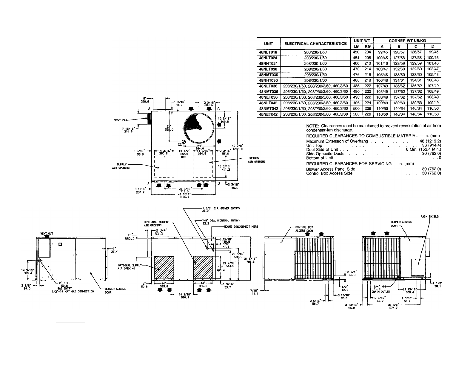
Fig. 2 — 48 Dimensional Drawing, Sizes NLT018 — NET042
Page 3
UNIT
48NHT036
48NVT036
48NHT042
48NVT042
48NLT048
48NMT048
48NHT048
48NVT048
48NLT060
48NMT060
48NHT060
48NVT060
ELECTRICAL CHARACTERISTICS
208/230/1/60, 208/230/3/60, 460/3/60
208/230/1/60, 208/230/3/60, 460/3/60
208/230/1/60, 208/230/3/60, 460/3/60 550
208/230/1/60, 208/230/3/60. 460/3/60
208/230/1/60, 208/230/3/60, 460/3/60
208/230/1/60, 208/230/3/60, 460/3/60
208/230/1/60, 208/230/3/60, 460/3/60
208/230/1/60, 208/230/3/60, 460/3/60,
208/230/1/60, 208/230/3/60, 460/3/60
208/230/1/60, 208/230/3/60, 460/3/60
208/230/1/60, 208/230/3/60, 460/3/60 616 280 139/63
208/230/1/60, 208/230/3/60, 460/3/60 616
NOTE. Clearances must be maintained to prevent recirculation of air from
condenser-fan discharge.
REQUIRED CLEARANCES TO COMBUSTIBLE MATERIAL - in. (mm)
Maximum Extension of Overhang 48(1219.2)
Unit Top ........................... ■ .36(914.4)
Duct Side of Unit . .... 6 Min. (152.4 Min.)
Side Opposite Ducts .30 (762.0)
Bottom of Unit. .... .0
REQUIRED CLEARANCES FOR SERVICING - in. (mm)
Blower Access Panel Side ... . 30 (762.0)
Control Box Access Side . . 30 (762.0)
UNIT WT
LB
530
536 243 119/54 148/67
556
574
580 263 130/59
586 265 131/59 161/73
586
604
610
A B
KG
241 117/53 147/67
249 122/55 152/69
252
124/56 153/69
261 128/58
265
131/59
274
136/62 165/75
277
138/63 166/75
280
139/63
CORNER WT LB/KG
158/72
159/72
161/73
168/76
168/76
C
148/67 118/54
149/68 120/54
153/69
154/70 125/57
159/72
160/73
162/73
162/73
166/75
167/76
169/77
169/77
D
123/56
129/59
131/59
132/60
132/60
137/62
139/63
140/64
140/64
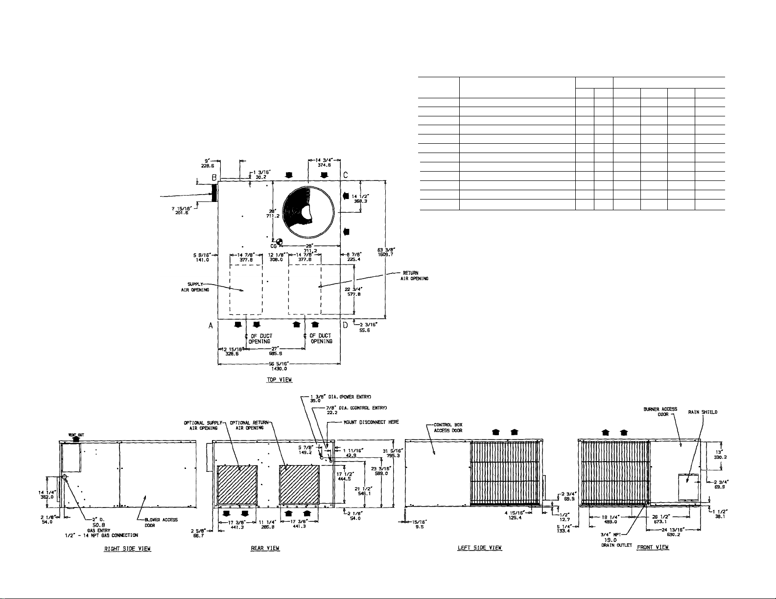
Fig. 3 — 48 Dimensional Drawing, Sizes NHT036 — NVT060
Page 4
Table 1 — Physical Data
UNIT SIZE 48
NOMINAL CAPACITY (ton)
OPERATING WEIGHT (lb)
COMPRESSORS
Quantity
REFRIGERANT*
REFRIGERANT METERING DEVICE
CONDENSER COIL
Rows
FIns/in.
CONDENSER FAN
Nominal Airflow (Cfm)
Nominal Speed (Rpm)
Quantlty...Dlameter (in.)
Motor Hp (single-phase)
EVAPORATOR COIL
Rows
Fins/ln.
EVAPORATOR FAN
Nominal Cfm
Nominal Speed (Rpm)
Diameter x Width (in.)
Motor Hp (single-phase)
FURNACE SECTION
Burner Orifice No. (Qty...drlll size)
Burner Orifice No. (Qty...drlll size)
Pilot Orifice Diameter (in. ...drill size)
Pilot Orifice Diameter (In.)
RETURN-AIR FILTERS (sq ln.)t
Disposable
Cleanable
•Operating charge is iisted on unit namepiate
tRequired fieid-suppiied fliter areas are based on the iarger of the ARi-rated (Air Conditioning & Refrigeration institute) cooling airflow or the heating
airflow at a velocity of 300 ft/min for disposable type or 450 ft/min for high-capacity type Air filter pressure drop must not exceed 0.08 in wg
••Single-phase units
ttThree-phase units
(three-phase)
(three-phase)
Natural Gas
Propane Gas
Natural Gas
Propane Gas
NLT018 NLT024
IV2
450
1
20 20
600 800
2 44
2. 55 2 55
288
192
NHT024
2
454
10 X 8
2 44 3 44 2. 44 3 44
NLT030
460 470 476
2000
825
V10
'/3
-
3 55 2 55 3 55
NMT030 NHT030
2V2
Reciprocating Hermetic. 3500 Rpm
1000
528
352 416
AcouRater® Piston
niR 77
NLT036
480
R-22
1 20
3
14
1100
4 44
4 55 3 .55 4 55
NMT036
486
2
2500
1100
V4
1/4
1200
V2
V2
3 44 4 44 4 42 5.44
624 720
NET036 NHT036
490
10 X 10
3
490
4 54 5 55 6 55
530
Vio
Va
3/4
480
%
2500**
3000tt
825**
lioott
1200
NVT036
536
6 .44
i
Step 2 - Provide Unit Support
ROOF CURB — Install accessory roof curb in accordance
with instructions shipped with curb. Install insulation, cant
strips, roofing and flashing. Ductwork must be attached to
curb.
IMPORTANT: The gasketing of the unit to the roof
curb is critical for water integrity. Install gasketing
material supplied with the roof curb. Improperly ap
plied gasketing also can result in air leaks and poor
unit performance.
Curb should be level to within */4 inch. This is necessary
for unit drain to function properly. Refer to Accessory Roof
Curb Installation Instructions for additional information as
required.
SLAB MOUNT — Place the unit on a solid, level concrete
pad that is a minimum of 4-in. thick with 2-in. above grade.
The slab should extend approximately 2-in. beyond the cas
ing on all 4 sides of the unit. Install a gravel apron in front
of condenser-air inlets to prevent obstruction of airflow by
grass or shrubs. Do not secure the unit to the slab except
when required by local codes.
Step 3 — Provide Clearances — The required min
imum operating and service clearances are shown in Fig. 2
and 3. Adequate combustion, ventilation and condenser air
must be provided.
The condenser fan discharges through the top of the unit.
Be sure that the fan discharge does not recirculate to the
condenser coil. Do not locate the unit in either a corner or
under an overhead obstruction. The minimum clearance
under a partial overhang (such as a normal house overhang)
is 48-in. above the unit top. The maximum horizontal ex
tension of a partial overhang must not exceed 48 inches.
A CAUTION
Do not restrict condenser airflow. An air restriction at
either the outdoor-air inlet (the entire surface of the out
door coil) or the fan discharge can be detrimental to
compressor life.
Do not place the unit where water, ice or snow from an
overhang or roof will damage or flood the unit. Do not in
stall the unit on carpeting, tile or other combustible mate
rials. The unit may be installed on wood flooring or on Class
A, B or C roof covering materials.
Step 4 — Rig and Place Unit — Use spreader bars
and crate top when rigging the unit. The units must be rigged
for lifting as shown in Fig. 4. Refer to Fig. 4 for rigging
weight and Table 1 for operating weight. Use extreme cau
tion to prevent damage when moving the unit. Unit must
remain in an upright position during all rigging and mov
ing operations. The unit must be level for proper conden
sate drainage; therefore, the ground-level pad or accessory
roof-mounting curb must be level before setting the unit in
place. When a field-fabricated support is used, be sure that
the support is level and properly supports the unit.
A CAUTION
When installing the unit on a rooftop, be sure the roof
will support the additional weight. Refer to Fig. 4 for
corner weight information.
Page 5
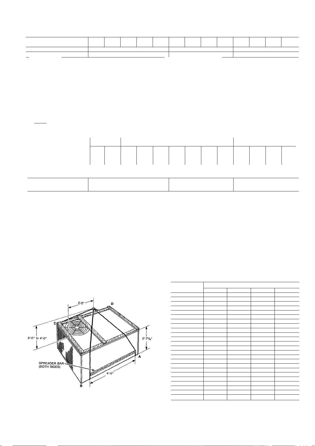
Table 1 — Physical Data (cent)
NLT
UNIT SIZE 48
NOMINAL CAPACITY (ton)
OPERATING WEIGHT (lb) 496 500 500
COMPRESSORS
Quantity______
REFRIGERANT*
REFRIGERANT METERING
DEVICE
CONDENSER COIL
Rows
FIns/ln.
CONDENSER FAN
Nominal Airflow (Cfm)
Nominal Speed (Rpm)
Quantlty...Dlameter (In.)
Motor Hp (single-phase)
EVAPORATOR COIL
Rows
Fins/ln.
EVAPORATOR FAN
Nominal Cfm
Nominal Speed (Rpm)
Diameter x Width (In.)
Motor Hp (single-phase)
FURNACE SECTION
Burner Orifice No.
Burner Orifice No.
Pilot Orifice Diameter
Pilot Orifice Diameter (In.)
RETURN-AIR FILTERS (sq ln.)t
Disposable 720
Cleanable 480
•Operating charge is iisted on unit namepiate
tRequired fieid-suppiied fiiter areas are based on the iarger of the ARi-rated (Air Conditioning & Refrigeration institute) cooling airflow or the heating airflow at a velocity of 300 ft/min
for disposable type or 450 ft/min for high-capacity type. Air filter pressure drop must not exceed 0 08 in wg
(three-phase)
_________
(three-phase)
(Qty...drlll size) Natural Gas
(Qty...drill size) Propane Gas
(In. ...drill size) Natural Gas
Propane Gas
3 44
3 55
NMT
042
2500 3000 3500
V2 3/4
’/2 3/4
4. 44
4 55 4 54 5 55
042
NET
042
3Vz
4 42 5 44
NHT
NVT
042
550
6 44
6. 55 3 .55 4 55 5 55 6 54 3 55
NLT
042
556 574 580
Reciprocating Hermetic, 3500 Rpm
3 44 4 44 5 44 6 42 3 44
NMT
048
R-22
AocuRater® Piston
018 77
NHT
048
048
4
586 586
1
2
20
009
816
544 640
NVT
048
NLT
060
604
NMT
4 44 5 44
4 55 5 55
060
610
5
2000
960
NHT
060
616
NVT
060
616
I 3450
6 42
6 54
Step 5 — Connect Condensate Drain
NOTE: When installing condensate drain connection be sure
to comply with local codes and restrictions.
The unit disposes of condensate water through a %-in.
NPT drain fitting. See Fig. 2 and 3 for location.
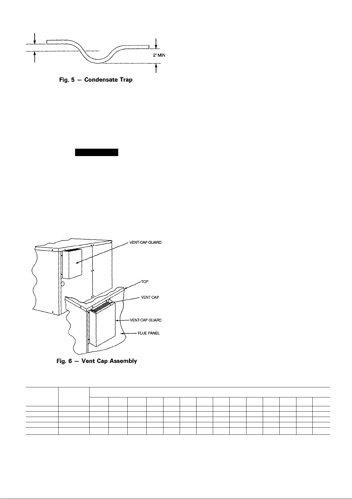
Install a 2-in. trap at the drain fitting to ensure proper
drainage. See Fig. 5. Make sure the outlet of the trap is at
least one-in. lower than the unit drain pan connection to
Fig. 4 - Suggested Rigging
prevent the pan from overflowing. Prime the trap with
water.
If the installation requires draining the condensate water
away from the unit, connect a drain tube using a minimum
of %-in. OD copper tubing, y4-in. galvanized pipe or %-in.
plastic pipe. Do not undersize the tube. Pitch the drain tube
downward at a slope of at least one inch in every 10 ft of
horizontal run. Be sure to check the drain tube for leaks.
UNIT 48
NLT018
NLT024 100
NHT024
NLT030 103 132 132 103
NMT030 105 133 133 105
NHT030 106 134 134 106
NLT036
NMT036 108
NET036 108 137 137 108
NHT036 117 147 148 118
NVT036 119 148 149 120
NLT042 109 139 139 109
NMT042
NET042 110 140 140 110
NHT042 117
NVT042
NLT048 128
NMT048
NHT048
NVT048
NLT060
NMT060
NHT060
NVT060
A
99
101
107
110 140
124
130 159 160 131
131
131
136 165 166 137
138 166 167
139 168 169
139 168 169 140
CORNER WT (LB)
B C D
126 126 99
127
129 129 101
136 136
137 137
147 147 117
153
158 159 129
161
161
127
140
154
162
162
100
107
108
110
125
132
132
139
140
Page 6
r MIN
Condensate water can be drained directly onto the roof in
rooftop installations (where permitted) or onto a gravel apron
in ground-level installations. When using a gravel apron,
make sure it slopes away from the unit.
Step 6 — Install Venting — The vent cap assembly
is shipped in the burner compartment. Remove the access
door to locate the assembly.
A CAUTION
The venting system is designed to ensure proper vent
ing. The vent cap assembly must be installed as indi
cated in this section of the unit Installation Instructions.
NOTE; Screw holes in the flue assembly and the unit flue
panel are not symmetrically located. Make sure they are
oriented properly when installing these components.
Refer to Fig. 6 and install the vent cap as follows:
1. Place vent cap assembly over flue panel. Orient screw
holes in vent cap with holes in flue panel.
2. Secure vent cap in place by inserting the single screw on
the right side of vent cap.
3. Place the vent cap guard over the vent cap. Orient holes
in vent cap guard with holes in vent cap and flue panel.
4. Secure the entire assembly with the remaining 2 screws
on the left side of vent cap and vent-cap guard
assembly.
Step 7 — Install Gas Piping — The gas supply pipe
enters the unit through the access hole provided. The gas
connection to the unit is made to the Vi-in. FPT gas inlet on
the manual shutoff or gas valve.
Install a separate gas supply line that runs directly from
the meter to the heating section. Refer to Table 2 and the
National Fuel Gas Code (NFGC) for gas pipe sizing. Do
not use cast-iron pipe. It is recommended that black iron
pipe is used. Check the local utility for recommendations
concerning existing lines. Choose a supply pipe that is large
enough to keep the pressure loss as low as practical. Never
use pipe smaller than the ‘A-in. FPT gas inlet on the unit
gas valve.
For natural gas applications, the gas pressure at unit gas
connection must not be less than 5 in. wg or greater than
13 in. wg while the unit is operating. For propane applica
tions, the gas pressure must not be less than 11 in. wg or
greater than 13 in. wg at the unit connection.
When installing the gas supply line, observe local codes
pertaining to gas pipe installations. Refer to the NFGC ANSI
(American National Standards Institute) Z223.1-1988 NFPA
(National Fire Protection Association) 54-1988 (in Canada,
CAN/CGA [Canadian Gas Association] B 149.1, (2)-M86).
In the absence of local building codes, adhere to the fol
lowing pertinent recommendations:
1. Avoid low spots in long runs of pipe. Grade all pipe
V4 inch in every 15 ft to prevent traps. Grade all hori
zontal runs downward to risers. Use risers to connect to
heating section and to meter.
2. Protect all segments of piping system against physical
and thermal damage. Support all piping with appropri
ate straps, hangers, etc. Use a minimum of one hanger
every 6 ft. For pipe sizes larger than Уг in., follow rec
ommendations of national codes.
3. Apply joint compound (pipe dope) sparingly and only to
male threads of joint when making pipe connections. Use
only pipe dope that is resistant to action of liquefied
petroleum gases as specified by local and/or national codes.
Never use Teflon tape.
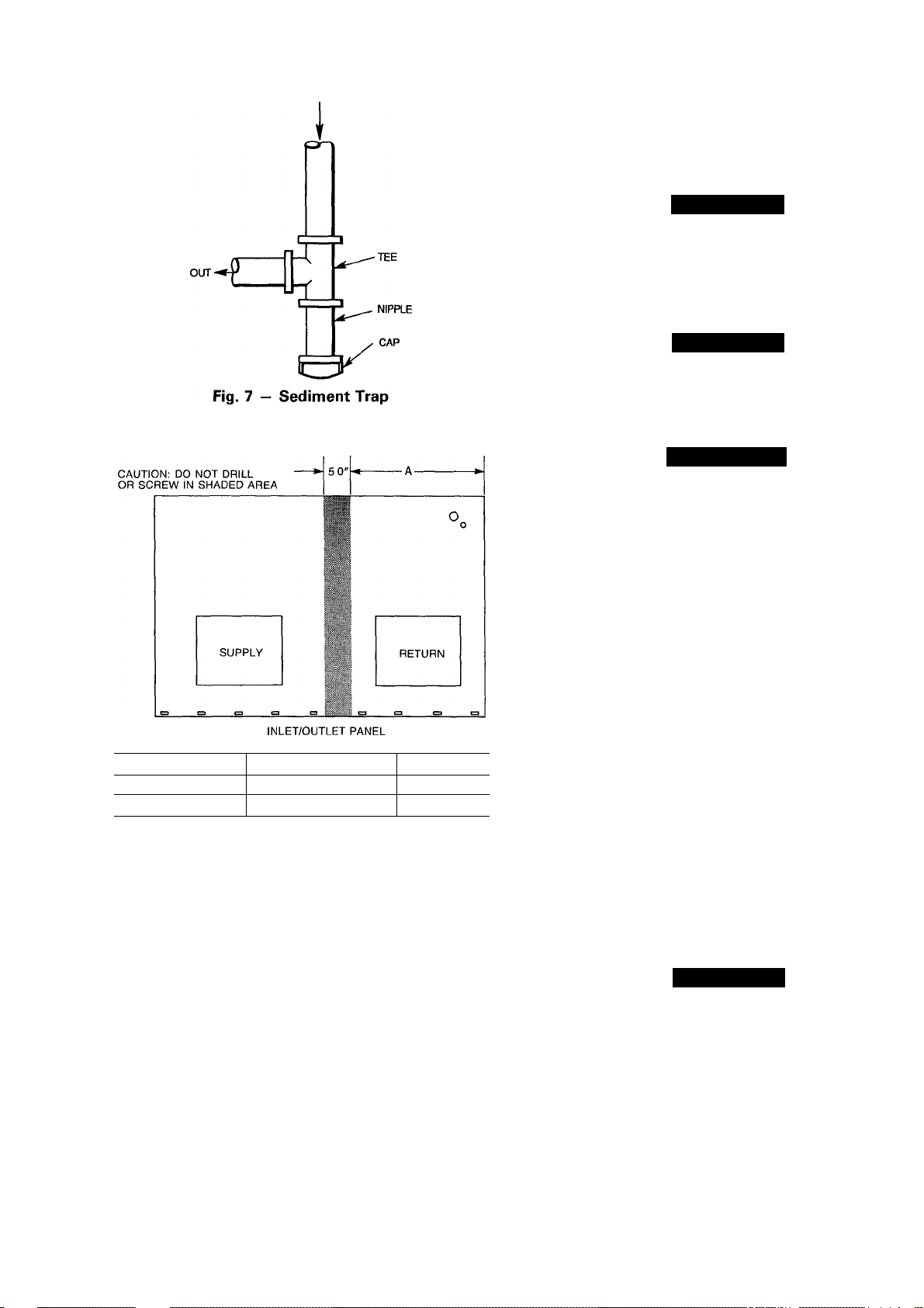
4. Install sediment trap in riser leading to heating section.
This drip leg functions as a trap for dirt and condensate.
Install trap where condensate cannot freeze. Install this
sediment trap by connecting a piping tee to riser leading
to heating section, so that straight-through section of tee
is vertical. See Fig. 7. Then, connect capped nipple into
lower end of tee. Extend capped nipple below level of
gas controls.
Table 2 — Maximum Gas Glow Capacity*
NOMINAL
IRON PIPE,
SIZE
(in.)
V2
%
1 1.049
VA 1.380
VA
‘Capacity of pipe in cu ft of gas per hr for gas pressure of 0 5 psig or less. Pressure drop of 0.5 in. wg
(based on a 0.60 specific gravity gas) Refer to Table C-4, NFPA 54-1984
fThls length includes an ordinary number of fittings
INTERNAL
DIAMETER
(In.)
.622 175 120
.824 360 250
1.610
10 20 30 40 50
680
1400 950
2100
97
465 375 320 285 260 240
1460
200
770 600 580
1180 990
82 73
170
151
900 810
LENGTH OF PIPE, FTf
60 70 80
61 57 53 50
66
125 118
138
530 490 460 430
220
750 690 650 620
90 100 125 150
110 103 93
205 195 175
400 360 325
44
160 145
550 500
175
—
40
84 77
300
460
200
—
72
135
280
430
Page 7
IN
testing of the piping systems when test pressure in excess
of 0.5 psig. Pressure test the gas supply piping system at
pressures equal to or less than 0.5 psig. The unit heating
section must be isolated from the gas piping system by clos
ing the external main manual shutoff valve and slightly open
ing the ground-joint union.
A CAUTION
Unstable operation may occur when the gas valve and
manifold assembly are forced out of position while con
necting improperly-routed rigid gas piping to the gas
valve. Use a backup wrench when making connection
to avoid strain on, or distortion of, the gas control
piping.
A CAUTION
If a flexible conductor is required or allowed by the au
thority having jurisdiction, black iron pipe shall be in
stalled at the gas valve and shall extend a minimum of
2 in. outside the unit casing.
A WARNING
Never use a match or other open flame when checking
for gas leaks. Never purge gas line into combustion
chamber. Failure to follow this warning could result in
an explosion causing personal injury or death.
Size
Small Cabinet
Large Cabinet NHT036-NVT060 25V2 in.
NLT018-NET042 20V2 in.
"A"
Fig. 8 — Location of Coii Area Not to be Drilled
5. Install an accessible, external, manual main shutoff valve
in gas supply pipe within 6 ft of heating section.
6. Install ground-joint union close to heating section be
tween unit manual shutoff and external manual main shut
off valve.
7. Pressure-test all gas piping in accordance with local and
national plumbing and gas codes before connecting pip
ing to unit.
NOTE; Pressure test the gas supply system after the gas
supply piping is connected to the gas valve. The supply
piping must be disconnected from the gas valve during the
8. Check for gas leaks at the field-installed and factoryinstalled gas lines after all piping connections have been
completed. Use soap-and-water solution (or method spec
ified by local codes and/or regulations).
Step 8 — Install Duct Connections — The unit
has duct flanges on the supply- and return-air openings on
the side and bottom of the unit. See Fig. 2 and 3 for con
nection sizes and locations.
NOTE: The design and installation of the duct system must
be in accordance with the standards of the NFPA for instal
lation of nonresidence-type air conditioning and ventilating
systems, NFPA No. 90A orresidence-type, NFPA No. 90B;
and/or local codes and residence-type, NFPA No. 90B; and/
or local codes and ordinances.
Adhere to the following criteria when selecting, sizing
and installing the duct system;
1. The unit is shipped in vertical configuration. To convert
unit to horizontal application, remove side duct covers,
save screws and install the covers on bottom duct
openings.
2. Select and size ductwork, supply-air registers and returnair grilles according to ASHRAE (American Society of
Heating, Refrigeration and Air Conditioning Engineers)
recommendations.
A CAUTION
When drilling the duct-system fastening holes into the
side of the unit instead of the unit duct flanges, use ex
treme care to avoid puncturing the coil or coil tubes.
See Fig. 8.
Page 8
3. Use flexible transition between rigid ductwork and unit
to prevent transmission of vibration. The transition may
be screwed or bolted to duct flanges. Use suitable gas
kets to ensure weather- and airtight seal.
4. Install external, field-supplied air filter(s) in return-air
ductwork where it is easily accessible for service. Rec
ommended filter sizes are shown in Table 1,
5. Size all ductwork for maximum required airflow (either
heating or cooling) for unit being installed. Avoid abrupt
duct size increases or decreases.
6. Adequately insulate and weatherproof all ductwork lo
cated outdoors. Insulate ducts passing through uncondi
tioned space, and use vapor barrier in accordance with
latest issue of SMACNA (Sheet Metal and Air Condi
tioning Contractors National Association) and ACCA (Air
Conditioning Contractors of America) minimum instal
lation standards for heating and air conditioning sys
tems. Secure all ducts to building structure,
7. Flash, weatherproof and vibration-isolate all openings
in building structure in accordance with local codes and
good building practices.
Step 9 — Install Electrical Connections
A WARNING
The unit cabinet must have an uninterrupted, unbroken
electrical ground to minimize the possibility of per
sonal injury if an electrical fault should occur. This ground
may consist of an electrical wire connected to the unit
ground lug in the control compartment, or conduit ap
proved for electrical ground when installed in accor
dance with NEC (National Electrical Code) ANSI/
NFPA (latest edition) (in Canada, Canadian Electrical
Code CSA C22.1) and local electrical codes. Do not
use gas piping as an electrical ground. Failure to ad
here to this warning could result in personal injury or
death.
A CAUTION
Failure to follow these precautions could result in dam
age to the unit being installed:
1. Make all electrical connections in accordance with NEC
ANSI/NFPA (latest edition) and local electrical codes
governing such wiring. In Canada, all electrical connec
tions must be in accordance with CSA Standard C22.1
Canadian Electrical Code Part 1 and applicable local codes.
Refer to unit wiring diagram.
2. Use only copper conductor for connections between field-
supplied electrical disconnect switch and unit. DO NOT
USE ALUMINUM WIRE.
3. Be sure that high-voltage power to unit is within oper
ating voltage range indicated on unit rating plate. On 3phase units, ensure that phases are balanced within 2%.
Consult local power company for correction of im
proper voltage and/or phase balance.
4. Insulate low-voltage wires for highest voltage contained
within conduit when low-voltage control wires are run
in same conduit as high-voltage wires.
5. Do not damage internal components when drilling through
any panel to mount electrical hardware, conduit, etc.
HIGH-VOLTAGE CONNECTIONS - The unit must have
a separate electrical service with a field-supplied, water
proof, fused disconnect switch mounted at, or within sight
from, the unit. Refer to the unit rating plate for maximum
fuse/circuit breaker size and minimum circuit amps (ampac
ity) for wire sizing. See Table 3 for electrical data.
The field-supplied disconnect switch box may be mounted
on the unit over the high-voltage inlet hole in the control
corner panel. See Fig. 2 and 3.
Proceed as follows to complete the high-voltage connec
tions to the unit;
1. Connect ground lead to chassis ground connection when
using separate ground wire.
2. Run high-voltage leads into unit control box and con
nect to contactor. See unit wiring label, and Fig. 9.
A CAUTION
TRANSFORMER CONTAINS AUTO
RESET OVERCURRENT PROTECTOR.
IT MAY RESET WITHOUT WARNING
STARTING HEATING OR COOLING
SECTION OF THIS PRODUCT.
DISCONNECT POWER PRIOR TO
SERVICING.
THIS COMPARTMENT MUST BE
CLOSED EXCEPT WHEN SERVICING.
316056-201 REV A
Fig. 9 — Transformer Label
Page 9
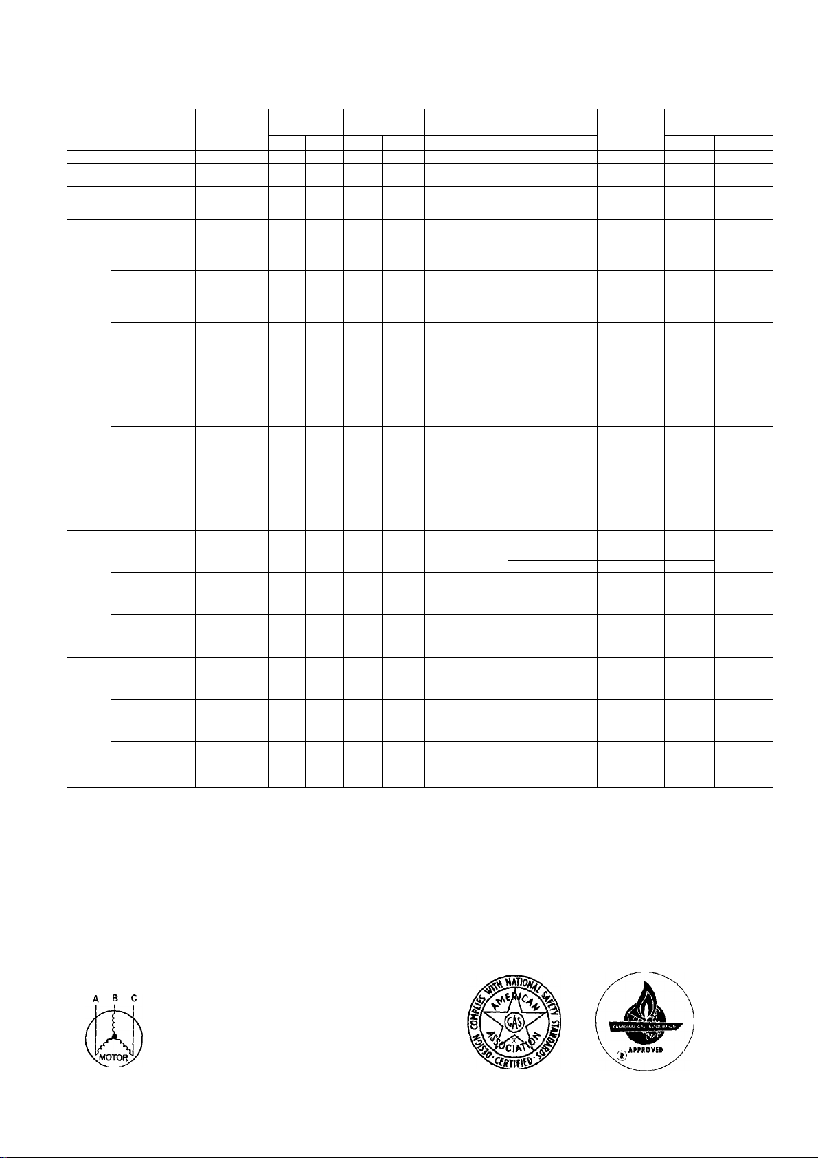
Table 3 — Electrical Data
UNIT
SIZE
01B
024
030
036
042
048
060
AWG
FLA
LRA
MCA
MOCP
NEC
RLA
NOTES:
1
In compliance with NEC requirements for multimotor and combination load
and equipment (refer to NEC Articles 430 and 440), the overcurrent pro
tective device for the unit shall be fuse or HACR breaker
Unbalanced 3-Phase Supply Voltage
Never operate a motor where a phase imbalance in supply voltage is greater
than 2% Use the following formula to determine the % voltage imbalance.
% Voltage Imbalance
_ y max voltage deviation from average voltage
NOMINAL
V-PH-HZ
208/230-1-60
208/230-1-60
208/230-1-60
208/230-1-60
208/230-3-60
460-3-60
208/230-1-60
208/230-3-60
460-3-60
208/230-1-60
208/230-3-60
460-3-60
208/230-1-60
208/230-3-60
460-3-60
American Wire Gage
Full Load Amps
Locked Rotor Amps
Minimum Circuit Amps
Maximum Overcurrent Protection
National Electrical Code
Rated Load Amps
Example: Supply voltage is 460-3-60
MODEL NO.
48
NLT018 187 253 82 49 0
NLT024
NHT024
NLT030
NMT030
NHT030
NLT036
NMT036
NET036
NHT036
NVT036
NLT036
NMT036
NET036
NHT036
NVT036
NLT036
NMT036
NET036
NHT036
NVT036
NLT042
NMT042
NET042
NHT042
NVT042
NLT042
NMT042
NET042
NHT042
NVT042
NLT042
NMT042
NET042
NHT042
NVT042
NLT048
NMT048
NHT048
NVT048
NLT048
NMT048
NHT048
NVT048
NLT048
NMT048
NHT048
NVT048
NLT060
NMT060
NHT060
NVT060
NLT060
NMT060
NHT060
NVT060
NLT060
NMT060
NHT060
NVT060
average voltage
AB = 452 volts
BC = 464 volts
AC = 455 volts
Average Voltage
VOLTAGE
RANGE
Min Max RLA
187 253
187 253 14.3
187
187
414
187
187
414 506 77 41 0 1 2
187 253 26 5
187 253 16.8
187
187 253 30 7
187
414 506 104 55 0 1 2
452 + 464 -r 455
3
1371
—JT— =457
11.6
11.6
253 21 1
14.7
253
506 7 1
23.9 95.4 1 5
253
15.3
253
253
253
82
21 4
COMPR
LRA
61 0
61.0
86.0 08
100 0 1 5
67.0
34 0
82 0
1140
84 0
42 0 1 2
135 0
130 0 22
CONDENSER-
FAN MOTOR
FLA
08
08
1 9
1.9
1.9
22
22
1.2
1.9
1 9
1 9
2.2
2.2
2.1
22
2 1
Determine maximum deviation from average voltage.
(AB) 457 - 452 =5 volts
(BC) 464 - 457 =7 volts
(AC) 457 - 455 =2 volts
Maximum deviation is 7 volts.
Determine % voltage imbalance
% Voltage Imbalance =100 x
This amount of phase imbalance is satisfactory as it is below the maximum
allowable 2%
IMPORTANT: If the supply voltage phase imbalance is more than 2%,
contact your local electric utility company immediately
EVAPORATOR-
FAN MOTOR
FLA
2.5
2.5 12 17 1 25
25
25
3.0
30
3.0
45
45
45
30
30
45
45
45
1 5
1 5
23
23
23
3.0
3.0
45
45
4.5
30
3.0
45
4.5
4.5
1 5
1 5
23
23
2.3
4.5
45
4.5
62
45
45
4.5
62
23
23
2.3
32
62 6 46 7
6.2
32 12 17.4 25
AWG MIN
WIRE SIZE
7
"457
14
10
8
10
14
8
10
14
8
6
10
14
8
= 1.53%
POWER SUPPLY
MCA
13 6 20
21 2
21.2
21 7
30.9
30 9
32.4
32 4
32.4
23.3
23 3
24 8
25 1
25 1
11 6
11 6
124
124
12.4
34 3
34 3
35 9
35.9
35 9
24 0
24.0
25 5
25.8
25 8
123
12.3
13 1
13.1
13 1
39 7
39 7
39.7
41 4
27.7
27 7
27 7
29 4
13.8
138
138
147
35 5 50
MOCP
30
40
30
15
50
35
35
40
40
40
20
60
40
20
60
Page 10

SPECIAL PROCEDURES FOR 208-V OPERATION
Á WARNING
Make sure that the power supply to the unit is switched
OFF before making any wiring changes. Electrical shock
can cause personal injury or death.
1. Disconnect the orange transformer-primary lead from the
contactor. See unit wiring label.
2. Remove the tape and cover from the terminal on the end
of the red transformer-primary lead.
3. Save the cover.
4. Connect the red lead to the contactor terminal from which
the orange lead was disconnected.
5. Using the cover removed from the red lead, insulate the
loose terminal on the orange lead.
6. Wrap the cover with electrical tape so that the metal ter
minal cannot be seen.
Indoor blower motor speeds should be changed for 208-v
operation. In the unit control box, change motor leads on
the printed circuit board so that high speed is used for cool
ing and medium speed is used for heating. Do not change
blower speed setting for 460-v rated units. Refer to StartUp, Indoor Airflow and Airflow Adjustments section.
CONTROL VOLTAGE CONNECTIONS - Locate the room
thermostat on an inside wall in the space to be conditioned,
where it will not be subjected to either a cooling or heating
source or direct exposure to sunlight. Mount the thermostat
4 to 5 ft above the floor.
Use no. 18 American Wire Gage (AWG) color-coded,
insulated (35 C minimum) wires to make the control volt
age connections between the thermostat and the unit. If the
thermostat is located more than 100 ft from the unit (as
measured along the control voltage wires), use no. 16 AWG
color-coded, insulated (35 C minimum) wires.
A grommeted, control voltage inlet hole is located in the
panel adjacent to the control access panel. Run the lowvoltage leads from the thermostat, through the inlet hole,
and to the control voltage terminals through a hole in the
bottom of the unit control box. Pass control voltage leads
through wire ties located under unit control box. Connect
the thermostat leads to the terminals as shown in Fig. 10.
HEAT ANTICIPATOR SETTING - The room thermostat
heat anticipator must be adjusted properly to ensure proper
heating performance. Set the heat anticipator, using an
THERMOSTAT (TYPICAL)
-TERMINAL BOARD
I I I
¿)(y)¿(¿
(U);j~
(L2)i^
(Q)- —
CONTROL BOX
FIELD CONTROL-VOLTAGE WIRING
FIELD HIGH-VOLTAGE WIRING
rh
GND
3-PHASE
UNITS ONLY
Fig. 10 — High- and Control-Voltage Connections
-CONTACTOR TERMINALS
(SEE UNIT WIRING LABEL)
V-*cnKr-—
FIELD SUPPLIED
FUSED DISCONNECT
POWER
SUPPLY
ammeter between the W and R terminals to determine the
exact required setting.
NOTE: For thermostat selection purposes, use 0.6 amp for
the approximate required setting.
Failure to make a proper heat anticipator adjustment will
result in improper operation, discomfort to the occupants
of the conditioned space and inefficient energy utilization;
however, the required setting may be changed slightly
to provide a greater degree of comfort for a particular
installation.
TRANSFORMER CIRCUIT PROTECTION - The unit
transformer contains an auto, reset overcurrent protector for
control circuit protection. If this device trips, it may reset
without warning, starting the heating or cooling section of
this product. Use caution when servicing; if overcurrent
protector continues to trip, there is a problem in the lowvoltage electrical circuit, such as an electrical short, ground
or transformer overload. Disconnect power, correct the con
dition, and check for normal unit operation.
PRE-START-UP
A WARNING
Failure to observe the following warnings could result
in serious personal injury:
1. Follow recognized safety practices and wear protec
tive goggles when checking or servicing refrigerant
system.
2. Do not operate compressor or provide any electric
power to unit unless compressor terminal cover is
in place and secured.
3. Do not remove compressor terminal cover until all
electrical sources are disconnected.
4. Relieve all pressure from system before touching or
disturbing anything inside terminal box if refriger
ant leak is suspected around compressor terminals.
5. Never attempt to repair soldered connection while
refrigerant system is under pressure.
6. Do not use torch to remove any component. System
contains oil and refrigerant under pressure. To re
move a component, wear protective goggles and pro
ceed as follows:
a. Shut off gas supply and then electrical power to
unit.
b. Relieve all pressure from system using both high-
and low-pressure ports.
c. Cut component connecting tubing with tubing cut
ter and remove component from unit.
d. Carefully unsweat remaining tubing stubs when
necessary. Oil can ignite when exposed to torch
flame.
Proceed as follows to inspect and prepare the unit for ini
tial start-up:
1. Remove alt access panels.
2. Read and follow instructions on all WARNING, CAU
TION and INFORMATION labels attached to, or shipped
with, unit.
Make the following inspections:
a. Inspect for shipping and handling damages such as
broken lines, loose parts, disconnected wires, etc.
b. Inspect for oil at all refrigerant tubing connections
and on unit base. Detecting oil generally indicates
10
Page 11

ф
a refrigerant leak. Leak-test all refrigerant tubing con
nections using electronic leak detector, or liquidsoap solution. If a refrigerant leak is detected, see
Start-Up, Check for Refrigerant Leaks section.
c. Inspect all field- and factory-wiring connections. Be
sure that connections are completed and tight.
d. Inspect coil fins. If damaged during shipping and han
dling, carefully straighten fins with a fin comb.
3. Verify the following conditions:
A WARNING
Do not purge gas supply into the combustion cham
ber. Do not use a match or other open flame to
check for gas leaks. Failure to follow this warning
could result in an explosion causing personal injury
or death.
a. Make sure that gas supply has been purged, and that
all gas piping has been checked for leaks.
b. Make sure that outdoor-fan blade is correctly posi
tioned in fan orifice. Blades should clear fan motor
by no more than V4 inch.
c. Make sure that air filter(s) is in place.
d. Make sure that condensate drain pan and trap are filled
with water to ensure proper drainage.
e. Make sure that all tools and miscellaneous loose parts
have been removed.
START-UP
Check for Refrigerant Leaks — Proceed as follows
to locate and repair a refrigerant leak and to charge the unit;
1. Locate leak and make sure that refrigerant system pres
sure has been relieved.
2. Repair leak following accepted practices.
NOTE; Install a filter drier whenever the system has been
opened for repair.
3. Add a small charge of R-22 refrigerant vapor to system
and leak-test unit.
4. Evacuate refrigerant system if additional leaks are not
found.
5. Charge unit with R-22 refrigerant, using a volumetric-
charging cylinder or accurate scale. Refer to unit rating
plate for required charge. Be sure to add extra refrig
erant to compensate for internal volume of filter drier.
Start-Up Heating Section and Make
Adjustments
A CAUTION
Complete the required procedures given in Start-Up sec
tion before starting the unit.
Do not jumper any safety devices when operating the unit.
Make sure that burner orifices are aligned properly. Un
stable operation may occur when the burner orifices in the
manifold are misaligned.
NOTE: When installing a unit in extremely cold climate
areas, a run-in period for the inducer motor is recom
mended. After the unit is installed, disconnect the red wire
from terminal 2 at the ignition control (IGN) and jumper
terminals R-W at the control voltage terminal board. The
inducer motor should run but the burner will not ignite. Al
low inducer motor to run for 4 to 5 hours. Reconnect red
wire to terminal 2 at IGN and remove R-W jumper at the-
control voltage terminal board. Proceed as follows to com
plete heating section start-up.
Follow the lighting instructions on the heating section op
eration label (located inside the burner access door) to start
the heating section.
When lighting the unit for the first time, perform the
following:
If the gas supply pipe was not purged before connecting
the unit, it will be full of air. It is recommended that the
ground joint union be loosened, and the supply line be al
lowed to purge until the odor of gas is detected. Never purge
gas lines into a combustion chamber. Immediately upon de
tection of gas odor, retighten the union. Allow 5 minutes to
elapse, then light unit using the following steps.
CHECK HEATING CONTROL - Start and check the unit
for proper heating control operation as follows: (See fur
nace lighting instructions located inside burner access panel.)
1. Place the room thermostat SYSTEM switch in the HEAT
position and the fan switch in the AUTO, position.
2. Set the heating temperature control of the thermostat above
room temperature.
3. Observe that after built-in time delays, the pilot auto
matically lights, the burners light and the blower motor
starts.
4. Observe that the burners and pilot go out, and that after
a built-in delay the blower motor stops when the heating
control setting of the thermostat is satisfied.
NOTE: The 060-size 460-v models are equipped with a 3phase blower motor. Check blower wheel for correct rota
tion as indicated by arrow on blower housing. If blower
wheel rotates in opposite direction, reverse any 2 blower
motor leads or any 2 line voltage leads. Recheck blower
wheel rotation if necessary to reverse leads.
CHECK GAS INPUT — Check gas input and manifold pres
sure after unit start-up. (See Table 4.) If adjustment is re
quired, proceed as follows.
The rated gas inputs shown in Table 4 are for altitudes
from sea level up to 2000 ft above sea level. These inputs
are based on natural gas with a heating value of 1050 Btu/
ft^ at 0.65 specific gravity, or propane gas with a heating
value of 2500 Btu/fr at 1.5 specific gravity. For elevations
above 2000 ft, reduce input 4% for each 1000 ft above sea
level. When the gas supply being used has a different heat
ing value or specific gravity, refer to national and local codes,
or contact your Distributor or Branch to determine the re
quired orifice size.
A CAUTION
These units are designed to consume the rated gas in
puts using the fixed orifices at specified manifold pres
sures as shown in Table 4. DO NOT REDRILL THE
ORIFICES UNDER ANY CIRCUMSTANCES.
ADJUST GAS INPUT — The gas input to the unit is de
termined by measuring the gas flow at the meter or by mea
suring the manifold pressure. Measuring the gas flow at the
meter is recommended for natural gas units. The manifold
pressure must be measured to determine the input of pro
pane gas units.
Measure Gas Flow (Natural Gas Units') — Minor adjust
ment to the gas flow can be made by changing the manifold
pressure. The manifold pressure must be maintained be
tween 3.2 and 3.8 in. wg. If larger adjustments are
required, change main burner orifices following the recom
mendations of national and local codes.
11
Page 12

Table 4 — Rated Gas Inputs
UNIT 48
NLT018,024,030
NLT036,042; NHT024; NMT030 3 50
NLT048,060; NMT036,042; NHT030
NET036,042
NMT048,060; NHT036.042
NHT048,060; NVT036,042
NVT048,060
‘When a 48N unit is converted to propane, the unit must be modified. See kit instructions.
tBased on altitudes from sea level up to 2000 ft above sea level. For altitudes above 2000 ft, reduce
Input rating 4% for each 1000 ft above sea level In Canada, from 2000 ft above sea level to 4500 ft
above sea level, derate the unit 10%.
NUMBER
OF
ORIFICES
GAS SUPPLY PRESSURE
Min Max Min Max
2 5.0
4
4 5.0 136 11 0 13.6
5 5.0 13.6
6 5.0 13.6 11.0 13.6
6 50 13.6 11.0
5.0 13.6
NOTE; All other appliances that use the same meter must
be turned off when gas flow is measured at the meter.
Proceed as follows:
1. Turn off gas supply to unit.
2. Remove pipe plug on outlet of gas valve, then connect
manometer at this point. Turn on gas to unit.
3. Record number of seconds for gas meter test dial to make
(in. wg)
Natural Propane
13.6
13.6 11.0 13.6 3.5
13 6 35
11 0
11.0 13.6 3.5
11.0 13.6 3.5 10.5
136 3.5 10.5
Measure Manifold Pressure (Propane Units') — The main
burner orifices on a propane gas unit are sized for the unit
rated input when the manifold pressure is 10.5 in. wg.
unit:
1. Turn off gas to unit.
2. Remove pipe plug on outlet of gas valve, then connect
one revolution.
4. Divide number of seconds in Step 3 into 3600 (number
of seconds in one hour).
3. Turn on gas to unit.
4. Remove cover screw over regulator adjustment screw
5. Multiply result of Step 4 by the number of cu ft shown
for one revolution of test dial to obtain cu ft of gas flow
5. Adjust regulator adjustment screw for a manifold pres
per hour.
6. Multiply result of Step 5 by Btu heating value of gas to
obtain total measured input in Btuh. Compare this value
with heating input shown in Table 4. (Consult the local
gas supplier if the heating value of gas is not known.)
6. Replace cover screw.
7. Turn off gas to unit. Remove manometer from pressure
Example: Assume that the size of test dial is one cu ft, one
revolution takes 30 seconds, and the heating value of the
gas is 1050 Btu/ft^. Proceed as follows:
1. 30 seconds to complete one revolution.
2. 3600 30 = 120.
3. 120 X 1 = 120 ft^ of gas flow/hr.
4. 120 X 1050 = 126,000 Btuh input.
If the desired gas input is 125,000 Btuh, only a minor
change in the manifold pressure is required.
Observe manifold pressure and proceed as follows to
adjust gas input;
1. Remove cover screw over regulator adjustment screw
on gas valve.
2. Turn regulator adjustment screw clockwise to increase
gas input, or turn regulator adjustment screw counter
clockwise to decrease input. Manifold pressure must be
between 3.2 and 3.8 in. wg.
CHECK BURNER FLAME — Observe the unit heating
operation, and watch the burner flames through the obser
vation port to see if they are light blue and soft in appear
ance, and that the flames are approximately the same for
each burner. See Fig. 11.
BLOWER HEAT-RELAY OPERATION - Blower relay
PCI (see the unit wiring diagram) is located in the control
box and adjusts to permit either longer or shorter “off” cy
cles. The “on” cycle is factory set for one minute on tim
ing. The adjusting dial on the relay (see Fig. 12) is factory
set at the minimum position to provide optimum perfor
mance for most installations. On unusual installations, the
length of time the blower remains on may need to be
increased. To increase blower operation time, rotate the ad
justing dial counterclockwise. To decrease blower opera
tion time, rotate dial clockwise.
AIRFLOW AND TEMPERATURE RISE - The heating
MANIFOLD
PRESSURE
(in. wg)
Natural
3.5 10.5
35 10.5
Proceed as follows to adjust gas input on a propane gas
manometer at this point.
on gas valve.
sure reading of 10.5 in. wg. Turn adjusting screw clock
wise to increase manifold pressure, or turn adjusting screw
counterclockwise to decrease manifold pressure.
tap. Replace pipe plug on gas valve, then turn on gas to
unit. Check for leaks.
section for each size unit is designed and approved for heat
A WARNING
Unsafe operation of the unit may result if manifold
pressure is outside this range. Personal injury or unit
damage may result.
ing operation within the temperature-rise range stamped on
the unit rating plate.
Table 5 shows the approved temperature-rise range for
each unit, and the air delivery cfm at various temperature
rises. The heating operation airflow must produce a tem
3. Replace cover screw cap on gas valve.
4. Turn off gas supply to unit. Remove manometer from
pressure tap. Replace pipe plug on gas valve. Turn on
perature rise that falls within the approved range.
Refer to Indoor Airflow and Airflow Adjustments sec
tion to adjust heating airflow when required.
gas to unit. Check for leaks.
NATURAL GAS
Orifice
Propane
10.5 44 40,000
10.5 44 60,000
105 44
Heating
Orili
Size
(Btuh)t
42 96,000
44 100,000
44 120,000
42 144,000
PROPANE*
Input
80,000 55
Orifice
Drill
Size
55
55
55
54
54
55
Heating
Input
(Btuh)t
40,000
60,000
80,000
96,000
100,000
120,000
144,000
12
Page 13

PILOT FLAME BURNER FLAME
fl
will close the IFR2 relay 60 seconds after the burners are
ignited and the blower motor (IFM) will start. When the
thermostat is satisfied, the R and W circuit is opened and
power is removed from the PC2 inducer control and the ig
nition module (IGN), which causes the MV to close in
stantly and the IM is deenergized. The electronic timer PCI
will keep the IFM running an additional 60 to 90 seconds.
Then the blower stops and the unit is on standby until an
other call for heat.
NOTE; If the main limit switch opens due to the unit over
heating, the IFM is turned on through the electronic board.
NOTE: When the unit is initially powered, IER2 will close
and run the IFM for the duration of the off-delay cycle (60
to 90 seconds).
If the pilot fails to light within a 120-second trial for ig
nition period from the initial call for heat, the IGN will go
into a Retry mode after a period of approximately 5 min
utes (following the 2-minute trial for ignition period). If the
pilot again fails to light, IGN will go into Retry mode; this
cycle will be repeated until the pilot light ignites. If the pi
lot flame has been established but then extinguishes, the
IGN will immediately reset as if it were the initial call for
heat. If this occurs more than 3 times, the IGN will lock
out the system, and the diagnostic LED (located on the IGN)
will flash. To reset, open the R-W thermostat circuit for 30
seconds and reclose. If the diagnostic LED glows con
stantly, replace control.
LIMIT SWITCHES — Normally closed limit switch LS com
pletes the control circuit through the thermostat R circuit.
See Fig. 13 and 14. Should the leaving-air temperature rise
above the maximum allowable temperature, the limit switch
opens and the R control circuit “breaks.” Any interruption
in the R control circuit instantly closes the gas valve and
stops gas flow to the burners and pilot. The IFM continues
to run until the LS resets.
SAFETY CHECK OF LIMIT CONTROL - The control
shuts off the gas supply and energizes the circulating-air
blower motor if the furnace overheats.
The recommended method of checking this limit control
is to gradually block off the return air after the furnace has
been operating for a period of at least 5 minutes. As soon
as the limit control functions, the return-air opening should
be unblocked to permit normal air circulation. By using this
method to check the limit control, it can be established that
the limit is functioning properly and the furnace will “fail
safe” if there is a restricted circulating air supply or motor
failure. If the limit control does not function during this
test, the cause must be determined and corrected.
HEATING SEQUENCE OF OPERATION - See Fig. 13
for single-phase operation and Fig. 14 for 3-phase opera
tion. Room thermostat calls for heat, closing circuit be
tween R and W 24-V control circuit terminals. (Power to
the R terminal is supplied through LS and ALS safety
switches.) The PC2 inducer control board is energized through
the normally closed set of contacts of pressure switches (CPS),
which starts the inducer motor (IM). The IM comes up to
speed, and the vacuum in the collector box increases, open
ing the normally closed and closing the normally open
contacts of the pressure switch (PS), energizing the circuit
to the ignition control (IGN) and the pilot valve (PV). If
theflame sensor proves the presence of the pilot flame, the
t
internal switching of the ignition control deenergizes the
spark generator and energizes the main gas valve (MV) and
the IFR2 electronic timer. Gas flows to the main burners
and is ignited by the pilot flame. The PCI electronic timer
When the air temperature at the limit switch drops to the
low-temperature setting of the limit switch, the switch closes
and completes the R control circuit. The electric-spark ig
nition system cycles and the unit returns to normal heating
operation.
BLOWER AUXILIARY LIMIT SWITCH - Blower aux
iliary limit switch ALSl is a temperature-actuated auto, re
set switch and is connected in series with the limit switch
LS. The function of the switch is to prevent abnormal blower
compartment temperatures. The switch is mounted on the
blower housing. When the temperature at the auxiliary switch
reaches the maximum allowable temperature, the R control
circuit “breaks”, closing the gas valve and stopping gas
flow to the burners and pilot. The switch will automatically
reset when the blower compartment temperature returns to
normal. The IFM continues to run until ALSl resets.
ROLLOUT AUXILIARY LIMIT SWITCH - Rollout aux
iliary limit switch ALS2 is a temperature-actuated manual
reset switch connected in series with limit switch LS and
blower auxiliary limit switch ALSl. The function of the
switch is to close the main gas valve in the event of flame
rollout. The switch is located above the main burners. When
the temperature at the auxiliary switch reaches the maxi
mum allowable temperature, the R control circuit trips, clos
ing the gas valve and stopping gas flow to the burners and
pilot. To reset the switch, push in the red button. If the
switch cycles again, shut down the unit and call for service.
The IFM continues to run until ALS2 is reset.
13
Page 14

r
SIN6LE STA6E HEAT K SIN6LE STAGE COOL
THERMOSTAT CTYPJ
■@-RED-
BUC
KED -
ORN -
TRAN
BRN —
^ ®©<£>
® PCI ®
® I—I I—3 ®
<!> 0 <»> 0 0
♦-0
r^Pi'
IGN o
PS
ALS1 ALS2 C -
CAP. -
1,2
COMP
EG
GV
IFM
IFR1
IFR2
IM
IR
IGN
LS
NOTES:
1. 230-v operation as shown. For 208-v operation, reverse red and orn leads of transformer.
2. Symbols are an electrical representation only.
3. If any of the original wire, as supplied, must be replaced, use minimum 105° C wiring
4. Use copper wire only for field power supply leads.
5. Compressor and fan motors provided with inherent thermal protection.
Auxiliary Limit Switch (SPST)
NC (Blower)
Auxiliary Limit Switch (SPST)
NC (Rollout)
Contactor
Capacitors (Run)
Compressor
Equipment Ground
Gas Valve
Indoor Fan Motor
Indoor Fan Relay
(SPOT) NO (Cooling)
Indoor Fan Relay
(SPST) NO (Heating)
Inducer Motor
Inducer Relay (DPST) NO
Ignitor
Limit Switch (SPST) NC
material.
LEGEND
MV
OFM
P
PCI
PC2
PI
PS
PV
ST
TRANS
Mam Valve
Outdoor Fan Motor
Pilot (Flame Sensing)
Printed Circuit Board (Blower)
Printed Circuit Board (Inducer)
Pilot Ignitor
Pressure Switch (SPOT) NC
Pilot Valve
Start Thermistor (024-042 only)
Transformer
Field High-Voltage Wiring
Factory High-Voltage Wiring
Factory Low-Voltage Wiring
Field Low-Voltage Wiring
Marked Connection
e
Unmarked Connection
o
internally Connected or
^ Wirenut
SO
o
Fig. 13 — Typical Single-Phase Wiring Diagram
Page 15

FIELD L3
POWER L2
SUPPLY
BLK-
^5—
{j^ I—@
©
ilHl—®
■ RSI ORN -
BRN
TRAN
SIN6LE 5TA6E HEAT S SIN6LE STA6E COOL
TfCRMOSTAT CTYPJ
EG
CAPI
1 Co o)
^ CAP2
ICOMPOWB^T arrangement“
ALS1
ALS2
C
CAP. 1,2
CCH
COMP
EG
GV
IPM
IFR1
IFR2
IM
IR
IQN
LS
NOTES:
1. 230-v operation as shown. For 208-v operation, reverse red and orn leads of transformer.
2. Symbols are an electnca) representation only.
3. If any of the original wire, as supplied, must be replaced, use minimum 105'^C wiring
material.
4. Use copper wire only for field power supply leads.
5. Compressor and fan motors provided with inherent thermal protection.
6. Three-phase motors protected under primary single-phase conditions.
Auxiliary Limit Switch (SPST)
NC (Blower)
Auxiliary Limit Switch (SPST)
NC (Rollout)
Contactor
Capacitors (Run)
Crankcase Heater
Compressor
Equipment Ground
Gas Valve
Indoor Fan Motor
Indoor Fan Relay
(SPOT) NO (Cooling)
Indoor Fan Relay
(SPST) NO (Heating)
Inducer Motor
Inducer Relay (DPST) NO
Ignitor
Limit Switch (SPST) NC
LEGEND
MV
OFM
p
PC1
PC2
PI
PS
PV
TRANS
Mam Valve
Outdoor Fan Motor
Pilot (Flame Sensing)
Printed Circuit Board (Blower)
Printed Circuit Board (Inducer)
Pilot Ignitor
Pressure Switch (SPOT) NC
Pilot Valve
Transformer
Field High-Voltage Wiring
Factory High-Voltage Wiring
Factory Low-Voltage Wiring
Field Low-Voltage Wiring
Marked Connection
©
Unmarked Connection
O
Internally Connected or
Wirenut
Fig. 14 — Typical 3-Phase Wiring Diagram
Page 16

Start-Up Cooling Section and Make
Adjustments
A CAUTION
Complete the required procedures given in the Pre-StartUp section before starting the unit.
Do not jumper any safety devices when operating
the unit.
Do not operate the compressor when the outdoor tem
perature is below 55 F (unless accessory low-temperature
kit is installed).
Do not rapid-cycle the compressor. Allow 5 minutes
between “on” cycles to prevent compressor damage.
CHECKING COOLING CONTROL OPERATION - Start
and check the unit for proper cooling control operation as
follows:
1. Place room thermostat SYSTEM switch in OFF posi
tion. Observe that blower motor starts when FAN switch
is placed in ON position and shuts down when FAN switch
is placed in AUTO, position.
2. Place SYSTEM switch in COOL position and FAN switch
in AUTO, position. Set cooling control below room tem
perature. Observe that compressor, condenser fan and
evaporator blower motors start. Observe that cooling
cycle shuts down when control setting is satisfied. The
blower motor has an off delay of approximately one minute
on shutdown.
3. When using an auto.-changeover room thermostat, place
both SYSTEM and FAN switches in AUTO, positions.
Observe that unit operates in heating mode when tem
perature control is set to “call for heating” (above room
temperature) and operates in cooling mode when tem
perature control is set to “call for cooling” (below room
temperature).
CHECKING AND ADJUSTING REFRIGERANT CHARGE
— The refrigerant system is fully charged with R-22 refrig
erant, tested and factory-sealed.
NOTE: Adjustment of the refrigerant charge is not required
unless the unit is suspected of not having the proper R-22
charge. Eor all applications, the correct R-22 charge for the
best performance is the charge that results in a suction gas
superheat of 5 F at the compressor inlet when the unit is
operating at the ARI rating conditions of 95 F dry-bulb (db)
outdoor and 80 F db/67 F wet-bulb (wb) indoor.
A superheat charging label is attached to the outside of
the compressor access door. The label includes a “Super
heat Charging Table” and a “Required Suction-Tube Tem
perature (F)” chart.
An accurate superheat thermocouple- or thermistor-type
thermometer, a sling psychrometer and a gage manifold are
required when using the superheat charging method for eval
uating the unit charge. Do not use mercury or small dial-
type thermometers because they are not adequate for this
type of measurement.
A CAUTION
When evaluating the refrigerant charge, an indicated
adjustment to the specified factory charge must always
be very minimal. If a substantial adjustment is indi
cated, an abnormal condition exists somewhere in the
cooling system, such as insufficient airflow across
either coil or both coils.
Proceed as follows:
1. Remove caps from lowfittings.
and high-pressure service
2. Using hoses with valve core depressors, attach low- and
high-pressure gage hoses to low- and high-pressure ser
vice fittings, respectively.
3. Start unit in cooling mode and let unit run until system
pressures stabilize.
4. Measure and record the following.
a. Outdoor ambient-air temperature (F db).
b. Evaporator inlet-air temperature (F wb).
c. Suction-tube temperature (F) at low-side service
fitting.
d. Suction (low-side) pressure (psig).
5. Using “Superheat Charging Table,” compare outdoorair temperature (F db) with evaporator inlet-air temper
ature (F wb) to determine desired system operating su
perheat temperature. See Table 6.
6. Using “Required Suction-Tube (F)” table, compare de
sired superheat temperature with suction (low-side)
operating pressure (psig) to determine proper suctiontube temperature. See Table 7.
7. Compare actual suction-tube temperature with proper
suction-tube temperature. Using a tolerance of ± 3 F,
add refrigerant if actual temperature is more than 3 F
higher than proper suction-tube temperature, or remove
refrigerant if actual temperature is more than 3 F lower
than required suction-tube temperature.
NOTE: If the problem causing the inaccurate readings is a
refrigerant leak, refer to Start-Up, Check for Refrigerant
Leaks section.
INDOOR AIRFLOW AND AIRFLOW ADJUSTMENTS
A CAUTION
For cooling operation, the recommended airflow is 350
to 450 cfm per each 12,000 Btuh of rated cooling ca
pacity. For heating operation, the airflow must pro
duce a temperature rise that falls within the range stamped
on the unit rating plate.
Direct-drive blower motors are factory connected to de
liver the proper heating and cooling airflows at normal ex
ternal static pressures (medium speed cooling, low speed
heating for 230-v units) and high speed cooling (units with
460-V have medium speed cooling and high speed heating).
For 208-v operation on 208/230-v rated direct drive units,
interchange motor leads to high speed for cooling and
medium speed for heating operation.
Table 5 shows the temperature rise at various airflow rates.
Tables 8 and 9 show both heating and cooling airflows at
various external static pressures. Refer to these tables to
determine the airflow for the system being installed.
NOTE: Be sure that all supply- and return-air grilles are
open, free from obstructions and adjusted properly.
A WARNING
Disconnect electrical power to the unit before changing
blower speed. (Be sure to turn off gas supply before
disconnecting electrical power.) Electrical shock can cause
personal injury or death.
A CAUTION
Do not change the blower-motor lead connections on
460-V units from the factory setting. Damage to unit
may result.
i
16
Page 17

Table 5 — Air Delivery (Cfm) at Indicated Temperature Rise and Rated Heating input
NOMINAL SIZE
NLT018,024,030
NHT024; NMT030
f
NLT036,042
NHT030; NMT036,042
NLT048
NLT060
NET036,042
NHT036,042; NMT048
NMT060
NVT036,042; NHT048 120,000
NHT060
NVT048,060
NOTE: Dashed areas of the table do not fall In the approved temperature rise range of the unit
HEATING
INPUT (Btuh)
40,000
60,000
60,000 - 80,000 - - - - - 1316
80,000 80,000
96,000 - - - 100,000
100,000
120,000 - - - 2539
144,000
20
- -
- - - - - 987 888
2370
2962 2370
- - - 2116
- -
- - - - - -
- - - -
30
25
987
1481 1269
1975 1693 1481
1975 1693 1481
2469
2116
UNIT TEMPERATURE RISE (T)
40 45
35
740 658
846
1111
1777
1851 1646
1851 1646 1481
2222 1975 1777
-
1316 1185
1316 1185
1580
2370 2133 1939 1777 1641
50 55
592 538
987
888
1185 1077
1422 1292 1185 1096
1481 1346 1234 1139
1777
60 65
493
808 740 683 634
740
808
987
1077
1346 1234
1616
1616
- - - - -
- - - - - -
1367
1481
1367
1481
70 75
-
- - 592 -
- - - -
911
846 790 -
1015 - -
- - -
- - - 1269
1185 1111
- - -
1523 1422
80
-
Table 6 — Superheat Charging Table*
TEMP (F)
55 9
60
65
70
75
80
85
90
95
100
105
110
115
50
—
— - —
— — - — -
52
12 14 17
7 10 12
- - 7
- - - - 5
- - - - - - 8 11 15 19
- - - - - - - 6
- - - - - - - - 8 12 15
- - - - - - - -
- - - - - - - - - 6
- - - - -
54 56 58
15
10 13 16 19
6
10 13 16
6 9 12
20
18
60 62
23 26
21 24
21 24 27
19 21
15
12 15
8
- - -
64
29 32 35
27 30 33 35
18
5
66
24
21 24 28
18 21 25
9 13 16 21
10 14
5 9 13
- -
68 70
37
30
27
33 36
30
22
18 22
11
72
40
38
33 36 39
31 34 37
28
26 30
24 27
20
17
15 20
8
14
74 76
42 45
40 43
38 41
31
25 29
23
22 26
18 23
35
33
31
27
25
•Superheat at suction service valve.
NOTE: Do not attempt to charge system under these conditions; refrigerant slugging may occur
Table 7 — Required Suction-Tube Temperature (F)*
TEMP (F)
61.5 64.2 67.1 70.0
0 35
2 37
4 39
6
8
10
12
41 43 45
43 45 47 49
45 47
47
14 49 51 53 55
16
51 53 55
16 53
20 55
22
57
24 59 61
26 61 63 65
28
30
32
34
63 65 67
65 67 69
67 69 71
69
36 71 73
38 73 75
40
•Temperature at suction service valve
75 77 79 81
37 39
39 41 43 45 47 49
41
49 51 53
55 57 59 61
57
59 61 63
71 73 75
43 45
49
59 61
63
75
77
41 43
47
51 53
57 59 61
65
67
69 71
71 73 75
73 75
77
79
73.0 76.0 79.2
47
49
51 53 55
55
57 59
63 65 67
65
67 69 71
69 71 73
77 79 81 83 85
79
81
83
45
49 51
51 53
55 57
57
63
67
73
77
81 83 85
83
85
47
59
61
63 65 67
65 67
69 71
75 77
77
79 81 83
85
87
49 51
51 53
53 55
55 57
57
59
61
63 65
69 71
73
75 77
79
87 89
89 91
82.4
85.7
59
61
63
69
73
75
79
81
87
17
Page 18

Table 8 — Dry Coil Air Delivery (Cfm)*
at Indicated External Static Pressure and Voltage
— Horizontal Discharge (Without Filter)
48
V-PH-HZ
NLT018, NLT024,
NHT024
208/230-1-60
NLT030, NMT030
208/230-1-60
NHT030, NLT036
NMT036, NLT042
NMT042
208/230-1-60
208/230-3-60,
460-3-60tt
NET036, 042
208/230-1-60
208/230-3-60
460-3-60tt
NHT036, NVT036
NHT042, NVT042
208/230-1-60
208/230-3-60
460-3-60tt
NLT048, NMT048
NHT048
208/230-1-60
208/230-3-60
460-3-60tt
NVT048
208/230-1-60
208/230-3-60
460-3-60tt
NLT060, NMT060
NHT060, NVT060
208/230-1-60
208/230-3-60
460-3-60tt
*Air delivery values are without air filter and are for dry coil. See Table 10 for wet coil pressure drop.
Deduct field-supplied air filter pressure drop and wet coil pressure drop to obtain external static
pressure available for ducting.
tFactory blower-motor speed setting for heating operation.
‘'Factory blower-motor speed setting for cooling operation.
ttDo not change blower speed settings for units with 460-v (high speed only).
NOTE: Do not operate the unit at a cooling airflow that is less than 350 cfm per each 12,000 Btuh of
rated cooling capacity. Evaporator coil icing may occur at airflows below this point. Water blow-off may
occur at airflows above 450 cfm per 12,000 Btuh of rated cooling capacity
MOTOR
SPEED
Lowf,
Med“
HI
Lowf,
Med“
Hi
Lowf,
Med“
Hi
Lowf,
Med“
Hi
Lowf,
Med“
Hi
Lowf,
Med“
Hi
Lowf,
Med“
Hi
Lowf,
Med“
Hi
in. wg
Watts
Cfm
Watts 511 483 464 440
Cfm
Watts 519
Cfm 1184 1163
Watts 620
Cfm 1443
Watts
Cfm
Watts 670
Cfm 1765 1705 1621 1521 1383
Watts
Cfm
Watts
Cfm
Watts 740 700
Cfm 1913 1820
Watts 790 760 720 690
Cfm 2032
Watts 770 730 690 650
Cfm 1945 1880
Watts 850
Cfm 2138
Watts
Cfm 1931 1901 1862 1813
Watts 1220 1165
Cfm 2376 2311 2244
Watts 1125
Cfm 2184 2125
Watts
Cfm 2380
0.0 0.1
451
1185 1129
1370
560 544 527 505
1515 1452
873 847 814 785 758
1717
1075 1030
2119
985 950
1220 1175
427
1291 1221 1142 1063
507
602
1414
650
1690 1645 1597 1550
2062
1942
810
2045
1055
2307
208 V
0.2 0.3
407 383
1088
1150
1376 1329 1279
1389 1308
2063
1026 979
492
1134 1105
581 559
631
995 960
1995 1913
660
1645 1544
1736
1844 1759 1636
1708 1611
1796
770 730
1943 1846
915
1080
1130
2170
1015 980
2000 1938
1125 1080
2262 2165
0.4 0.5
365 348
420
477 455 431 569
532 493 670
482 461
1227
602 573
930
1863 1793 2135 2066 1998
615 580
650 610
610 575 810 765 730
690
1738
890 860
1768 1703 2183 2125
1035 995
2083
940
1040
2095
0.0
501 477
922
1256 1195
402
1003 1442 1359
1064
1197
1105
542
1254 1857 1795 1708
734 987
1496 1979 1922 1859
900 1121 1087 1046
540 755 725 680
1428
1514
1508 2061 1970 1892 1813
655
1624
2003 2511
1880 2285 2225 2163 2106
1005
2024
561 533 514
1248
1519
610
1597 1530
720 701
1976 1909
850
2086
890 855
2178
820
1095
1300
905
1205 1125
1300 1250
2487
230 V or 460 V
0.1
0.2
0.3
457
1148
1081
1285 1202
557 542
1226 1211 1194 1164
652 631 609 582
1489 1449 1399
593 575 500
1464 1378 1293
680 653 625
1603 1457
911
945
1802
1017 981
1931 1858
1714 1603
1806
820 780
1983 1883
2081
1055 1010
1265 1220
2431
2412 2335 2260 2179
1782 1665
820 780 750
1941 1869 1769
2071 2005 1931 1854
1180 1120
2271 2168
2359
1095 1060 1030
1210 1165 1130 1085
0.4
433
415
1031
490
470
1119
527
505
1347
524
877 850
1734
650 610
750 715
695
655
1704
975 935
2045
0.5
398
971
452
1056
481
1120
543
1261
494
1164
594
1321
809
1667
952
1795
575
1495
675
1545
610
1580
715
1650
890
1085
2087
990
1980
2110
The heating and/or cooling airflow of 208/230-v directdrive blower motors can be changed by changing the lead
connections of the blower motor. The motor leads are colorcoded as follows:
black =high speed
blue = medium speed
red =low speed
NOTE: For all 208/230-v direct-drive units, the red motor
lead connected to the heat relay (L) on PCI blower control
determines the heating speed and resulting airflow, and the
blue motor lead connected to the cooling relay (H) on PCI
blower control determines the cooling speed and resulting
airflow. See the unit wiring label.
To change the heating and/or cooling speed of a directdrive motor, connect the appropriate color-coded lead at blower
motor connector to speed-tap desired. (See unit wiring
label.)
When installing a 208- or 230-v direct-drive unit that is
factory connected for heating and cooling speeds that are
not the same, and the same speed for both heating and cool
ing is required for a particular application, disconnect red
lead at terminal L of heat relay and connect to terminal MI
on PCI blower control. Connect a field-supplied jumper be
tween terminal L on heat relay and terminal H of cooling
relay. Connect blue lead at blower motor to appropriate speed
tap.
18
Page 19

Table 9 - Dry Coil Air Delivery (Cfm)*
at Indicated External Static Pressure and Voltage
— Vertical Discharge (Without Filter)
48
V-PH-HZ
NLT018, NLT024
NHT024
208/230-1-60
NLT030, NI\/1T030
208/230-1-60
NHT030, NLT036
NMT036, NLT042
NMT042
208/230-1-60
208/230-3-60
460-3-60tt
NET036, NET042
208/230-1-60
208/230-1-60
460-3-60tt
NHT036, NVT036
NHT042, NVT042
208/230-1-60
208/230-3-60
460-3-60tt
NLT048, NHT048
NMT048
208/230-1-60
208/230-3-60
460-3-60tt
NVT048
208/230-1-60
208/230-3-60
460-3-60tt
NLT060, NMT060
NHT060, NVT060
208/230-1-60
208/230-3-60
460-3-60tt
MOTOR
SPEED
Lowf,
Med* **
Hi
Lowf,
Med**
Hi
Lowf,
Med**
Hi
Lowf,
Med**
Hi
Lowf,
Med**
Hi
Lowf,
Med**
Hi
Lowf,
Med**
Hi
Lowf,
Med**
Hi
in. wg 0.0 0.1
Watts 451 417
Cfm
Watts 491
Cfm
Watts 509 497
Cfm 1155
Watts 600 582
Cfm 1411 1362
Watts
Cfm 1494
Watts 651
Cfm
Watts
Cfm
Watts
Cfm
Watts
Cfm 1797
Watts 750 715
Cfm 1885
Watts 710
Cfm
Watts 785 750
Cfm 1957 1873
Watts
Cfm
Watts
Cfm
Watts 1095 1025
Cfm
Watts 1190 1145
Cfm 2325 2255
1308 1234
1683 1615
1653 1611
1895 1839
1833 1768
1878 1821
1130
2199 2134
2125 2165
1102
1138
1138
522
1430
833
945 915
680
1709
1779
965
1097
463 454 420 400
504
631
792
645
680
915
208 V
0.2
1045
1162
1120
1326
1358
1536
1569
1803
1620
1704
1700
1786
1767
1026
2095
2005
1095
2187 2120
0.3 0.4
373 355 338 491
397
996 942 889 1196 1161
1084 1020 951
467 445 421
482
1104
561
1249
485
1273
610
1440
765
1518
890
1740 1029 1532 1971 1899 1830 1762 1673
610
680
1608
650
1599 1505 1390
720
1699 1598 1495 1997 1907 1817 1713 1618
875
1716 1654 1584 2060 1996
985
1073 1031 1218 1200
539 512 473 650 632
1195 1133 1493 1457 1412
663 440
1174 1058 1574 1507
575 540 517 695 680 658
1274
725 700 650 880 850 810 790
1473
865
580 545 510 705 670 640 595 570
1547 1448 1315 1855 1707 1684 1574
650 615 585 795 765 735 700 670
1507 1404 1906 1821 1722
600 570 520 740 705 665 635 600
685 650 610 835 805 770 735 705
840 800 770
985 970
1960 2060 1799 2280 2213 2168 2019 1921 1856
950 910
1887
1950
1050 1010 975 1280 1230 1190 1140 Ilio 1065
2050 1975 2437 2365 2390
1153 1763 1700 1619
1373 1805 1748 1692 1650 1582
805 770 1005
1830 2225 2170 2110 2050
0.0 0.1 0.2 0.3 0.4
0.5
382 541
1379
559
422
915
875 1175 1095 1065
600 573 555 523 491 470
1918
1025 985 935
1200
230 V or 460 V
467 447 423
1101
494 470 450 432
513
1301 1225 1143 1075 1002
532
547
1182
611
1431
965
935 900 865 820
1849
1165
1752
1921
1120
0.5
405 388
1050 993 932
517 495 471
1165
1358
1341 1237 1115
1492 1343
1623 1533 1410
1670 1561 1442
1075 1030 995
2220
1132
1088
589 562
1274
624
590 563
745
1498 1361
900 870 830
1075
1030 995
1030 1000 960
1987
2145
523
1218
1215
710
1475
1568
535
640
560
670
1506
1930
2075
*Air delivery values are without air filter and are for dry coil. See Table 10 for wet coil pressure drop
Deduct field-supplied air filter pressure drop and wet coil pressure drop to obtain external static
pressure available for ducting.
tFactory blower-motor speed setting for heating operation.
"Factory blower-motor speed setting for cooling operation.
tfDo not change blower speed settings for units with 460-v (high speed only).
NOTE: Do not operate the unit at a cooling airflow that is less than 350 cfm per each 12,000 Btuh of
rated cooling capacity. Evapoprator coil icing may occur at airflows below this point. Water blow-off
may occur at airflows above 450 cfm per 12,000 Btuh of rated cooling capacity
UNIT CONTROLS —All compressors have the following
internal-protection controls:
1. High-Pressure Relief Valve — This valve opens when
the pressure differential between the low and high side
becomes excessive.
2. Compressor Overload — This overload interrupts power
to the compressor when either the current or internal tem
perature become excessive, and automatically resets when
the internal temperature drops to a safe level.
This overload may require up to 60 minutes (or longer)
to reset; therefore, if the internal overload is suspected of
being open, disconnect the electrical power to the unit and
check the circuit through the overload with an ohmmeter or
continuity tester.
COOLING SEQUENCE OF OPERATION
NOTE; Although the actual unit wiring may vary slightly
from that shown in Fig. 13 and 14, the sequence of opera
tion will not be affected.
With the room thermostat SYSTEM switch in the COOL
position and the FAN switch in the AUTO, position, the
cooling sequence of operation is as follows:
When the room temperature rises to a point that is slightly
above the cooling control setting of the thermostat, the ther
mostat completes the circuit between thermostat terminal R
19
Page 20

to terminals Y and G. These completed circuits through the
thermostat connect contactor coil C (through unit wire Y)
and relay coil IFRl (through unit wire G) across the 24-v
secondary of transformer TRAN.
The normally open contacts of energized contactor C close
and complete the circuit through compressor motor COMP
and condenser fan motor OFM. Both motors start instantly.
The set of normally open contacts of energized relay IFRl
close and complete the circuit through evaporator blower
motor IFM. The blower motor starts instantly.
NOTE: The cooling cycle remains “on” until the room tem
perature drops to point that is slightly below the cooling
control setting of the room thermostat. At this point, the
thermostat “breaks” the circuit between thermostat termi
nal R to terminals Y and G. These open circuits de
energize contactor coil C and relay coil IFRl. The condenser
and compressor motors stop. After a 45-second delay, the
blower motor stops. The unit is in a “standby” condition,
waiting for the next “call for cooling” from the room
thermostat.
Table 10 - Wet Coil Pressure Drop
MODEL
018,024
030
036,042
048
060
AIRFLOW
(cfm)
600
700
800
900
900
1000
1200
1000
1200
1400
1600
1400
1600
1800
1700
1900
2100
2300
WET COIL PD
(In. wg)
038
.044
.052
062
.042
.050
.064
.038
.050
.064
.080
050
.060
.072
.100
.120
.140
.160
MAINTENANCE
To ensure continuing high performance, and to minimize
the possibility of premature equipment failure, periodic main
tenance must be performed on this equipment. This com
bination heating/cooling unit should be inspected at least
once each year by a qualified service person. To trouble
shoot heating or cooling of units, refer to Tables 11 and 12.
NOTE TO EQWPMENT OWNER: Consult your local Dealer
about the availability of a maintenance contract.
A WARNING
The ability to properly perform maintenance on this equip
ment requires certain expertise, mechanical skills, tools
and equipment. If you do not possess these, do not at
tempt to perform any maintenance on this equipment,
other than those procedures recommended in the Us
er’s Manual. FAILURE TO HEED THIS WARNING
COULD RESULT IN SERIOUS PERSONAL
INJURY AND POSSIBLE DAMAGE TO THIS
EQUIPMENT.
The minimum maintenance requirements for this equip
ment are as follows:
1. Inspect air filter(s) each month. Clean or replace when
necessary.
2. Inspect cooling coil, drain pan and condensate drain each
cooling season for cleanliness. Clean when necessary.
3. Inspect blower motor and wheel for cleanliness and check
lubrication each heating and cooling season. Clean and
lubricate (if required) when necessary.
4. Check electrical connections for tightness and controls
for proper operation each heating and cooling season.
Service when necessary.
5. Check and inspect heating section before each heating
season. Clean and adjust when necessary.
6. Check and clean vent screen if needed.
A warning
Failure to follow these warnings could result in serious
personal injury:
1. Turn off gas supply, then turn off electrical power
to the unit before performing any maintenance or
service on the unit.
2. Use extreme caution when removing panels and parts.
As with any mechanical equipment, personal injury
can result from sharp edges, etc.
3. Never place anything combustible either on, or in
contact with, the unit.
4. Should overheating occur, or the gas supply fail to
shut off, shut off the external main manual gas valve
to the unit, then shut off the electrical supply.
I
20
I
Page 21

Table 11 — Heating Troubleshooting Chart
#
#
SYMPTOM
IGN locked out.
Pilot will not light.
Burners will not ignite.
Inadequate heating.
Poor flame
characteristics.
CAUSE
LED flashing
LED glowing continuously
No spark at electrode
Spark shorting out to main burner Realign electrode tip away from main burner but maintain
No gas at pilot burner Clean pilot orifice.
Water in gas line
No power to furnace
No 24-v power supply to control circuit
Miswired or ioose connections
Dirty pilot — yellow flame Clean pilot orifice.
Pilot burning improperly — sharp blue flame Replace pilot.
Burned-out heat anticipator in thermostat
No gas at main burners
Broken thermostat wire
Dirty air filter
Gas input to furnace too low
Unit undersized tor application
Restricted airflow
Blower speed too low Use faster speed tap
Limit switch cycles main burners
Incomplete combustion results in;
Aldehyde odors, CO, sooting flame —
floating flame
Look for problems external to the ignitor module.
Replace IGN control.
Check air gap between electrode tip and pilot target
Gap should be as shown in Fig. 15.
Readjust as necessary.
Clean moisture or dirt accumulation on electrode ceramic with
cloth.
Cracked ceramic — replace pilot electrode assembly
Check for loose or broken wiring at and between electronic
control head and electrode Replace wire or tighten connection
as necessary.
Check fuses or circuit breaker to ensure voltage to unit.
Check for 24 v between TH and COM. If you read 24 v and
above steps have been completed, replace electronic ignition
control.
spark gap to pilot burner. See Fig. 15.
Check inlet pressure to gas value. Recommended operating
pressure 7-in. wg natural gas, 11-in. wg LP gas; 0.5 psig (13.6in. wg) max. pressure
Check for 24 v between terminals PV and COM If you read 24
V and above steps have been completed, replace gas valve.
Drain — install water trap.
Check power supply, fuses, wiring or circuit breaker.
Check transformer — replace if necessary.
Check all wiring and wirenut connections.
Replace thermostat.
1. Check for 24 v between terminals MV and COM on control
head If you read 24 v, replace gas valve portion of control
head/gas valve assembly.
2. If 24 V is not present, check flame sensor for cracked ce
ramic insulator or shorted sensor cable.
Run continuity check to locate break.
Clean or replace filter as necessary.
Check gas pressure at manifold. Clock gas meter for input. If
loo low, increase manifold pressure, or replace with correct
orifices.
Replace with proper unit — or add additional unit
Clean or replace filter — or remove any restriction.
Check temperature rise.
Dirty air filters — clean or replace.
Registers closed, restricted ductwork — open or remove
restriction.
Check temperature rise.
Check heat anticipator setting on thermostat — readjust.
Check all screws around flue outlets and burner compartment
— tighten.
LACK OF COMBUSTION AIR.
Cracked heat exchanger — replace.
Overfired furnace — reduce input, or change orifices.
Check vent for restriction — clean as required
Check orifice for burner alignment.
REMEDY
GR — Ground
LP — Liquid Propane
21
Page 22

Table 12 — Cooling Troubleshooting Chart
SYMPTOM
Cpmpressor and condenser fan will not
start.
Compressor will not
start but condenser
fan runs.
Compressor cycles
(other than normally
satisfying thermostat).
Compressor operates
continuously.
Excessive head pres-
sure.
Head pressure too low.
Excessive suction
pressure.
Suction pressure too
low.
CAUSE REMEDY
Power failure Call power company
Fuse blown or circuit breaker tripped Replace fuse or reset circuit breaker.
Defective thermostat, contactor, transformer or
control
relay
Insufficient line voltage Determine cause and correct.
Incorrect or faulty wiring Check wiring diagram and rewire correctly.
Thermostat setting too high
Faulty wiring or loose connections in compres
sor circuit
Compressor motor burner out, seized or internal
overload open
Defective run/start capacitor, overload, start re
lay
One leg of 3-phase power dead Replace fuse or reset circuit breaker.
Refrigerant overcharge or undercharge Blow refrigerant, evacuate system and recharge to nameplate.
Defective compressor Replace and determine cause
Insufficient line voltage Determine cause and correct
Blocked condenser
Defective run/start capacitor, overload or start
relay
Defective thermostat
Faulty condenser fan motor or capacitor Replace.
Restriction in refrigerant system
Dirty air filter Replace filter.
Unit undersized for load Decrease load or increase unit size.
Thermostat set too low Reset thermostat.
Low refrigerant charge Locate leak, repair and recharge.
Leaking valves in compressor
Air in system Blow refrigerant, evacuate system and recharge.
Condenser coil dirty or restricted
Dirty air filter
Dirty condenser coil Clean coil.
Refrigerant overcharged Purge excess refrigerant.
Air in system Blow refrigerant, evacuate system and recharge.
Condenser air restricted or air short-cycling
Low refrigerant charge
Compressor valves leaking
Restriction in liquid tube Remove restriction.
High heat load Check for source and eliminate.
Compressor valves leaking
Refrigerant overcharged Purge excess refrigerant.
Dirty air filter
Low refrigerant charge
Metering device or low side restricted
Insufficient evaporator airfiow Increase air quantity. Check filter — replace if
Temperature too low in conditioned area
Outdoor ambient below 55 F Install low-ambient kit.
Field-installed filter-drier restricted Replace.
Replace component.
Lower thermostat setting below room temperature
Check wiring and repair or replace.
Determine cause. Replace compresor.
Determine cause and replace.
Determine cause.
Determine cause and correct.
Determine cause and replace.
Replace thermostat.
Locate restriction and remove.
Replace compressor.
Clean coil or remove restriction.
Replace filter.
Determine cause and correct.
Check for leaks, repair and recharge.
Replace compressor
Replace compressor
Replace filter
Check for leaks, repair and recharge.
Remove source of restriction.
necessary.
Reset thermostat.
i
i
22
Page 23

i
Air Filter
A CAUTION
Never operate the unit without a suitable air filter in
the return-air duct system. Always replace the filter with
the same dimensional size and type as originally
installed. See Table 1 for recommended filter sizes.
Inspect air filter(s) at least once each month and replace
(disposable-type) or clean (cleanable-type) at least twice dur
ing each heating and cooling season or whenever the
filter(s) becomes clogged with dust and lint.
Replace filters with the same dimensional size and type
as originally provided, when necessary.
Unit Top Removal
A CAUTION
Condenser fan and motor are fastened to the unit top.
When removing the top, use extreme care to not pull
the fan motor leads loose.
NOTE; When performing maintenance or service proce
dures that require removal of the unit top, be sure to per
form all of the routine maintenance procedures that require
top removal, including: inspection of the heat exchanger
area, coil inspection and cleaning, and condensate drain pan
inspection and cleaning.
Only qualified service personnel should perform mainte
nance and service procedures that require unit top removal.
Refer to the following top removal procedures;
1. Turn off gas supply, then turn off electric power to unit.
2. Remove all screws that secure unit top, including screws
around 4 sides and those on top that screw into internal
divider panels. Save all screws.
3. Tape all side panels at each seam near unit top. Use tape
strips that are at least 5-in. long to prevent sides from
falling when top is removed.
4. Lift top from unit carefully. Set top on edge and make
sure that top is supported by unit side that is opposite
duct (or plenum) side. Use extreme care to prevent dam
age to the fan blades, motor and insulation.
5. Carefully replace and secure unit top to unit, using screws
removed in Step 2, when maintenance and/or service pro
cedures are completed. (Be sure to use original screws
that have rubber washers to seal out water when secur
ing top to internal divider panels.)
Evaporator Blower and Motor
NOTE: Motors without oilers are prelubricated. Do not at
tempt to lubricate these motors.
For longer life, operating economy and continuing effi
ciency, clean accumulated dirt and grease from the blower
wheel and motor annually.
Lubricate the motor every 5 years if the motor is used
intermittently (thermostat FAN switch in AUTO, position).
or every 2 years if the motor is used continuously (thermo
stat FAN switch in ON position).
A WARNING
Turn off the gas supply, then disconnect and tag elec
trical power to the unit before cleaning and lubricating
the blower motor and wheel. Failure to adhere to this
warning could cause personal injury or death.
To clean and lubricate the blower motor and wheel for
direct-drive models;
1. Remove and disassemble blower assembly as follows:
a. Remove blower access door.
b. Disconnect blower-motor leads from their termina
tion points at motor. Disconnect yellow lead from
control box at capacitor. Disconnect auxiliary limitswitch leads at switch.
c. Remove blower assembly from unit. Be careful not
to tear insulation in blower compartment.
d. Ensure proper reassembly by marking blower wheel
and motor in relation to blower housing before dis
assembly.
e. Loosen setscrew(s) that secures wheel to motor shaft,
remove screws that secure motor mount brackets to
housing and slide motor and motor mount out of
housing.
2. Lubricate motor as follows;
a. Thoroughly clean all accumulations of dirt or grease
from motor housing.
b. Remove dust caps or plugs from oil ports located at
each end of motor.
c. Use a good grade of SAE 20 nondetergent motor oil
and put one teaspoon (5 cc, Vie oz., or 16 to 25 drops)
in each oil port.
d. Allow time for oil to be absorbed by each bearing,
then wipe excess oil from motor housing.
e. Replace dust caps or plugs in oil ports.
3. Remove and clean blower wheel as follows:
a. Ensure proper reassembly by marking wheel orienta
tion and cutoff plate location.
b. Remove screws holding cut-off plate, and remove plate
from housing.
c. Lift wheel from housing. When handling and/or clean
ing blower wheel, be sure not to disturb balance weights
(clips) on blower wheel vanes.
d. Remove caked-on dirt from wheel and housing with
a brush. Remove lint and/or dirt accumulations from
wheel and housing with vacuum cleaner, using soft
brush attachment. Remove grease and oil with mild
solvent.
e. Reassemble wheel and cut-off plate into housing.
f. Reassemble motor into housing. Be sure setscrews
are tightened on motor shaft flats and not on round
part of shaft.
23
Page 24

Heating Section — Ensure dependable and efficient
heating operation by inspecting the heating section before
each heating season, and cleaning when necessary.
Proceed as follows to inspect and clean heating section:
1. Turn off gas and power to unit.
2. Remove burner access door.
3. Disconnect 2 wires from inducer motor.
4. Remove complete inducer assembly from unit.
5. Remove screws that secure collector box to heat ex
changer, exposing flue openings.
6. Remove flue choke.
7. Clean heat exchanger cells using field-provided small
wire brush, steel spring cable, reversible electric drill
and vacuum cleaner.
To assemble wire brush and steel spring cable:
NOTE: The items below can be purchased at a local
hardware store.
a. Use 4 ft of Vi in. diameter high-grade steel spring
cable (commonly known as drain cleanout or RotoRooter cable).
b. Use Vi-in. diameter wire brush (commonly known
as 25-caliber rifle cleaning bmsh).
c. Insert twisted wire end of brush into end of spring
cable; crimp tight with crimping tool or strike with
ball-peen hammer. Tightness is very important.
d. Remove metal sleeve from wire brush to allow proper
brush action.
To clean each heat exchanger cell:
a. Attach variable-speed reversible drill to end of spring
cable (end opposite brush).
b. Insert brush end of cable into upper opening of cell
and slowly rotate with drill. Do not force
cable. Gradually insert at least 3 ft of cable into 2
upper passes of cell.
c. Work cable in and out of cell 3 or 4 times to obtain
sufficient cleaning. Do not pull cable with great force.
Reverse drill and gradually work cable out.
d. Remove burner assembly.
e. Insert brush end of cable in lower opening of cell
and proceed to clean in same manner.
f. Repeat above procedures until each cell in unit is
cleaned.
g. Using vacuum cleaner, remove residue from each
cell.
h. Using vacuum cleaner with soft brush attachment,
clean burner assembly.
i. Reinstall burner assembly.
8. After cleaning, check sealant and gaskets to make sure
that they have not been damaged. If new sealants or
gaskets are needed, contact your Distributor.
9. Reinstall flue choke. Be sure all screws are in and are
tight.
10. Clean and replace flue collector assembly, making sure
all screws are secure.
11. Replace inducer assembly.
12. Reconnect the 2 wires to inducer motor.
13. Replace burner access door.
14. Turn on power and gas.
15. Set thermostat and check unit for proper operation.
Pilot — Inspect the pilot and clean (when necessary) at
the beginning of each heating season. Remove the accumu
lation of soot and carbon from the pilot. The pilot flame
must be high enough for proper contact with the flame sen
sor. Pilot flame must also come in contact with the pilot
hood (target) for proper operation. If the pilot flame ap
pears too hard (lifting and blowing) or too soft (unstable),
check inlet gas pressure for proper value. (See Table 4.)
The spark electrode must be located so the spark travels
through a combustible mixture of gas; if necessary, readjust
the electrode as shown in Fig. 15; be certain to maintain the
Vs-in. spark gap.
TARGET
Fig. 15 — Position of Electrode to Pilot
Condenser Coil, Evaporator Coil and Conden
sate Drain Pan — Inspect the condenser coil, evapo
rator coil and condensate drain pan at least once each year.
Proper inspection and cleaning requires the removal of the
unit top. See Unit Top Removal section.
The coils are easily cleaned when dry; therefore, inspect
and clean the coils either before or after each cooling sea
son. Remove all obstructions, including weeds and shrubs,
that interfere with the airflow, through the condenser coil.
Straighten bent fins with a fin comb. If coated with dirt or
lint, clean the coils with a vacuum cleaner, using the soft
brush attachment. Be careful not to bend the fins. If coated
with oil or grease, clean the coils with a mild detergentand-water solution. Rinse coils with clear water, using a
garden hose. Be careful not to splash water on motors, in
sulation, wiring or air filter(s). For best results, spray con
denser coil fins from inside to outside the unit. On units
with an outer and inner condenser coil, be sure to clean be
tween the coils. Be sure to flush all dirt and debris from the
unit base.
Inspect the drain pan and condensate drain line when in
specting the coils. Clean the drain pan and condensate drain
by removing all foreign matter from the pan. Flush the pan
and drain tube with clear water. Do not splash water on the
insulation, motor, wiring or air filter(s). If the drain tube is
restricted, clear it with a “plumbers snake” or similar probe
device.
i
24
Page 25

Condenser Fan
A CAUTION
Keep the condenser fan free from all obstructions to
ensure proper cooling operation. Never place articles
on top of the unit. Damage to unit may result.
Remove control and compressor access panels. Inspect
the fan blades for cracks or bends each year. Make sure
__________
that blades clear the motor by no more than % inch. If the
blade assembly has slipped down the motor shaft, adjust
the fan position on the motor shaft by loosening the set-
screw(s), then moving the blade assembly up. Be sure that
the setscrew(s) is on the flat(s) of the motor shaft before
tightening.
Electrical Controls and Wiring - Inspect and check
the electrical controls and wiring annually. Be sure to turn
off the gas supply, and then the electrical power to the unit.
Remove the control, blower and compressor compart
ment access panels to locate all the electrical controls and
wiring. Check all electrical connections for tightness. Tighten
all screw connections. If any smoky or burned connections
are noticed, disassemble the connection, clean all the parts,
restrip the wire end and reassemble the connection properly
and securely.
After inspecting the electrical controls and wiring, re
place all the panels. Start the unit, and observe at least one
complete heating cycle and one complete cooling cycle to
ensure proper operation. If discrepancies are observed in
either or both operating cycles, or if a suspected malfunc
tion has occurred, check each electrical component with the
proper electrical instrumentation. Refer to the unit wiring
label when making these checkouts.
NOTE: Refer to the heating and/or cooling sequence of op
f
eration in this publication as an aid in determining proper
control operation.
Refrigerant Circuit — Inspect all refrigerant tubing con
nections and the unit base for oil accumulations annually.
Detecting oil generally indicates a refrigerant leak.
If oil is detected or if low cooling performance is sus
pected, leak-test all refrigerant tubing using an electronic
leak-detector, or liquid-soap solution. If a refrigerant leak
is detected, refer to Start-Up, Check for Refrigerant Leaks
section.
If no refrigerant leaks are found and low cooling perfor
mance is suspected, refer to Checking and Adjusting Re
frigerant Charge section.
Gas Input — The gas input does not require checking
unless improper heating performance is suspected. If a prob
lem exists, refer to Start-Up section.
Evaporator Airflow — The heating and/or cooling air
flow does not require checking unless improper perfor
mance is suspected. If a problem exists, be sure that all
supply- and return-air grilles are open and free from ob
structions, and that the air filter is clean. When necessary,
refer to Indoor Airflow and Airflow Adjustment section to
check the system airflow.
Metering Device Servicing - See Fig. 16 for me
tering device components. The piston has a refrigerant me
tering orifice through it. The retainer forms a sealing sur
face for liquid line flare connection. To check, clean or replace
piston:
1. Shut off power to unit.
2. Remove refrigerant from unit using approved refrigerant
removal methods from both high- and low-service port
connections.
3. Remove liquid line flare connections from metering
device.
4. Note position of arrow on metering device body with
respect to unit.
5. Pull retainer out of body. Be careful not to scratch flare
sealing surface. If retainer does not pull out easily, care
fully use locking pliers to remove retainer. Replace
scratched or damaged retainer.
6. Slide piston out by inserting a small, soft wire through
metering hole (18-gage thermostat wire). See that me
tering hole, sealing surface around piston cones and fluted
portion of piston are not damaged.
7. Use the chart on the unit access panel to determine proper
arrangement and size of piston. See Table 13 for piston
sizes.
8. Clean piston refrigerant-metering orifice.
9. Replace retainer 0-ring (part no. 99CC501052).
Liquid Line Strainer — The liquid line strainer (t<
protect metering device) is made of wire mesh and locate«
in the liquid line on inlet side. Strainer is pressed into th
line. Remove strainer by threading a no, 10 sheet-metal scre\
into strainer and pulling the screw with pliers.
FLARE NUT
STRAINER
RETAINER
COOLING
Fig. 16 — Metering Device Components
25
Page 26

Table 13 — Piston Sizes
UNIT 48
NLT018
NLT024
PISTON IDENTIFICATION
59
63
NHT024 63
NLT030 73
NMT030 73
NHT030 73
NET036 80
NLT036 80
NMT036 80
NHT036 80
NVT036
NET042
NLT042
NMT042
NHT042
NVT042
NLT048
NMT048
NHT048
NVT048
NLT060
NMT060
NHT060
NVT060
80
82
82
82
84
84
86
86
86
86
101
101
101
101
26
Page 27

i
Copyright 1991 Carrier Corporation
B^DokM |4 PC 111 Catalog No. 564-920 Printed in U.S.A Form 48NT-20SI Pg 28 11-91 Replaces: 48NT-19SI
Tab hah a
Manufacturer reservea the right to discontinue, or change at any time, specifications or designs without notice and without incurring obligations.
 Loading...