

Page 1
48LJE/LJF004
48L J D/L J E/L J F005-007
HEATING & COOLING
Single-Package Rooftop Heating/Cooling Units
Installation, Start-Up, and Service Instructions
CONTENTS
Page
SAFETY CONSIDERATIONS ...
INSTALLATION .......................................................1
Step 1 — Provide Unit Support
• ROOF CURB
• SLAB MOUNT
Step 2 — Field Fabricate Ductwork .........................
Step 3 — Install External Trap for
Condensate Drain ..................................................
Step 4 — Rig and Place Unit ....................................
• POSITIONING
Step 5 — Install Flue Hood........................................
Step 6 — Install Gas Piping
Step 7 — Make Electrical Connections
• FIELD POWER SUPPLY
• FIELD CONTROL WIRING
• HEAT ANTICIPATOR SETTINGS
Step 8 - Make Outdoor-Air Adjustments and
Install Outdoor-Air Hood
• MANUAL OUTDOOR-AIR DAMPER
• TWO-POSITION DAMPER
• OPTIONAL ECONOMIZER
Step 9 — Adjust Evaporator-Fan Speed..................13
• DIRECT DRIVE MOTORS
• BELT DRIVE MOTORS
START-UP
................
................................
.....................................
...................
.......................................
SERVICE ..................
TROUBLESHOOTING
19
1
10
20,21
21-25
26-31
SAFETY CONSIDERATIONS
Installation and servicing of air-conditioning equipment
can be hazardous due to system pressure and electrical com
ponents. Only trained and qualified service personnel should
install, repair, or service air-conditioning equipment.
Untrained personnel can perform basic maintenance func
tions of cleaning coils and filters and replacing filters. All
other operations should be performed by trained service per
sonnel. When working on air-conditioning equipment, ob
serve precautions in the literature, tags and labels attached
to the unit, and other safety precautions that apply.
Follow all safety codes. Wear safety glasses and work
gloves. Use quenching cloth for unbrazing operations. Have
fire extinguishers available for all brazing operations.
A WARNING
Disconnect gas piping from unit when leak
testing at pressure greater than V2 psig. Pres
sures greater than ’/2 psig will cause gas valve
damage resulting in hazardous condition. If
gas valve is subjected to pressure greater than
■ /2 psig, it must be replaced before use. When
pressure testing field-supplied gas piping at
i
pressures of V2 psig or less, a unit connected
to such piping must be isolated by manually
closing the gas valve(s).
Before performing service or maintenance operations
on unit, turn off main power switch to unit. Electrical
shock could cause personal injury.
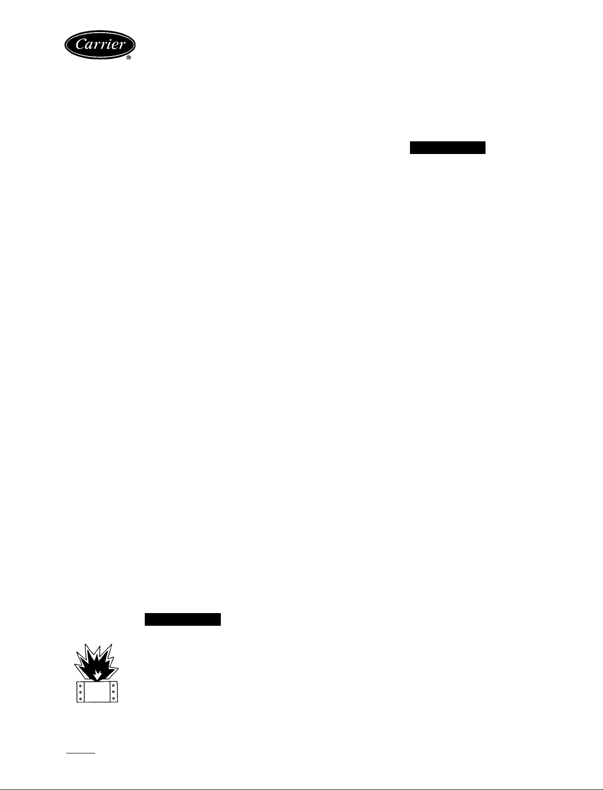
Unit is shipped in the vertical discharge configuration.
To convert to horizontal configuration, remove screws from
side duct opening covers and remove covers. Using the same
screws, install covers on vertical duct openings with the
insulation-side down. Seals around duct openings must be
tight. See Fig. 1.
IMPORTANT: An external filter kit MUST be used
or the filters MUST be field-installed outside the unit
on horizontal discharge applications with optional econ
omizer. Otherwise, the economizer must be partially
removed to access the filters. The area of the fieldinstalled filters should be equal to the area of the factoryinstalled filters.
Step 1 — Provide Unit Support
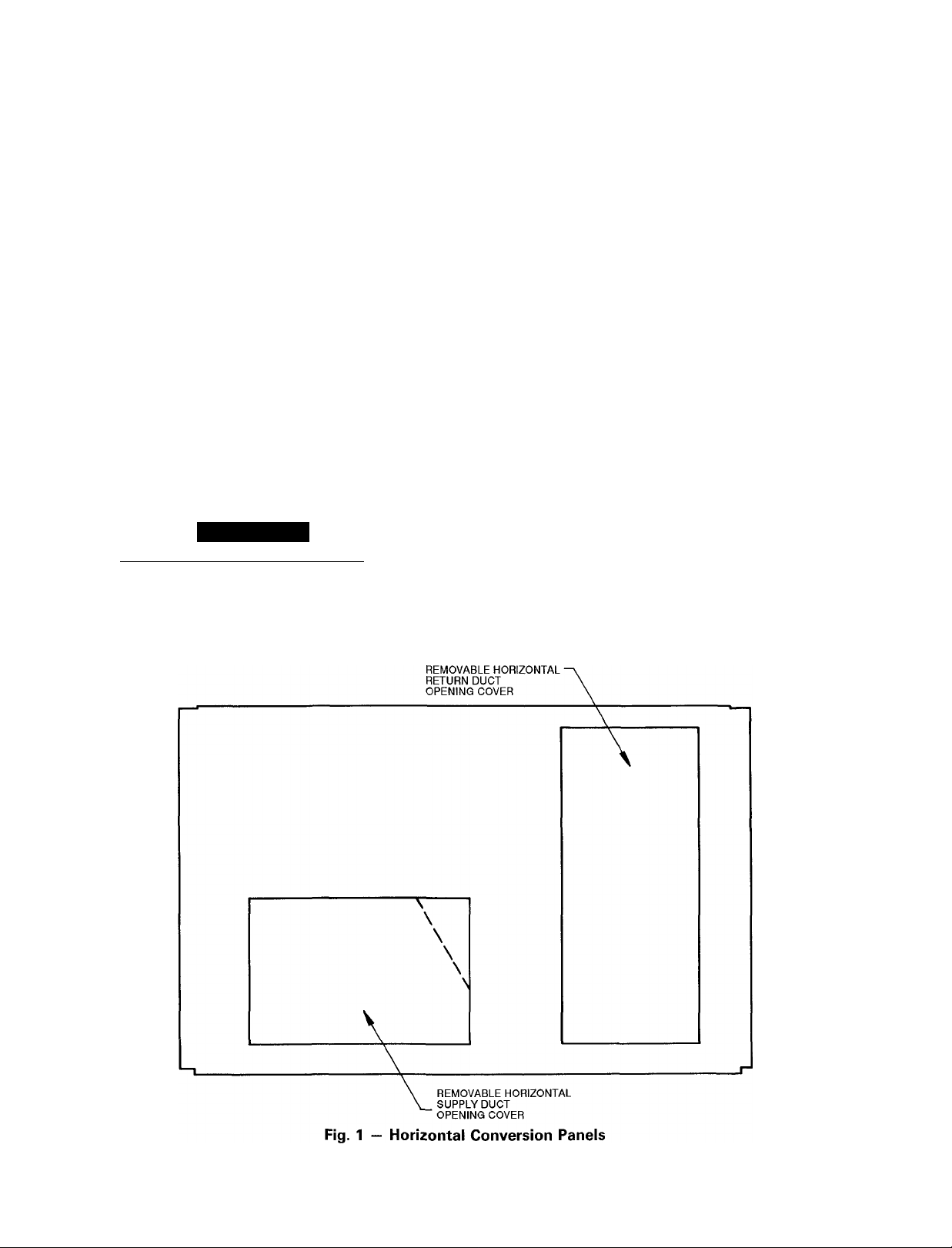
ROOF CURB — Assemble and install accessory roof curb
in accordance with instructions shipped with curb. See
Fig. 2. Install insulation, cant strips, roofing felt, and counter
flashing as shown. Ductwork must be attached to curb, not
to the unit. If gas, electric power, or control power is to be
routed through the curb, attach the accessory thm-the-curb
service connection plates to the roof curb in accordance with
the accessory installation instmctions. Connection plates must
be installed before unit can be set on roof curb.
IMPORTANT: The gasketing of the unit to the roof
curb is critical for a watertight seal. Install gasket sup
plied with the roof curb as shown in Fig. 2. Improp
erly applied gasket can result in air leaks and poor
unit performance.
Curb should be level. Unit leveling tolerances are shown
in Fig. 3. This is necessary for unit drain to function prop
erly. Refer to Accessory Roof Curb Installation Instruc
tions for additional information as required.
SLAB MOUNT (Horizontal Units Only) — Provide a level
concrete slab that extends a minimum of 6 in. beyond unit
cabinet. Install a gravel apron in front of condenser coil air
inlet to prevent grass and foliage from obstructing airflow.
NOTE: Horizontal units may be installed on a roof curb if
required.
Step 2 — Field Fabricate Ductwork — Secure all
ducts to roof curb and building structure on vertical units.
Do not connect ductwork to unit. For horizontal applica
tions, field-supplied flanges should be attached to horizon
tal discharge openings and all ductwork should be secured
to the flanges. Insulate and weatherproof all external duct
work, joints, and roof openings with counter flashing andmastic in accordance with applicable codes.
A WARNING
INSTALLATION
Book|1 |4 PC 111 Catalog No. 564-987 Printed in U S A Form 48LJ-7SI Pg 1 4-93 Replaces: 48LJ-5SI
Tab la 6a
Manufacturer reserves the right to discontinue, or change at any time, specifications or designs without notice and without incurring obiigations.
Page 2
Ducts passing through an unconditioned space must be
insulated and covered with a vapor barrier.
If a plenum return is used on a vertical unit, the return
should be ducted through the roof deck to comply with ap
plicable fire codes.
A minimum clearance is not required around ductwork.
Cabinet return air static shall not exceed —.35 in. wg with
economizer or — .45 in. wg without economizer.
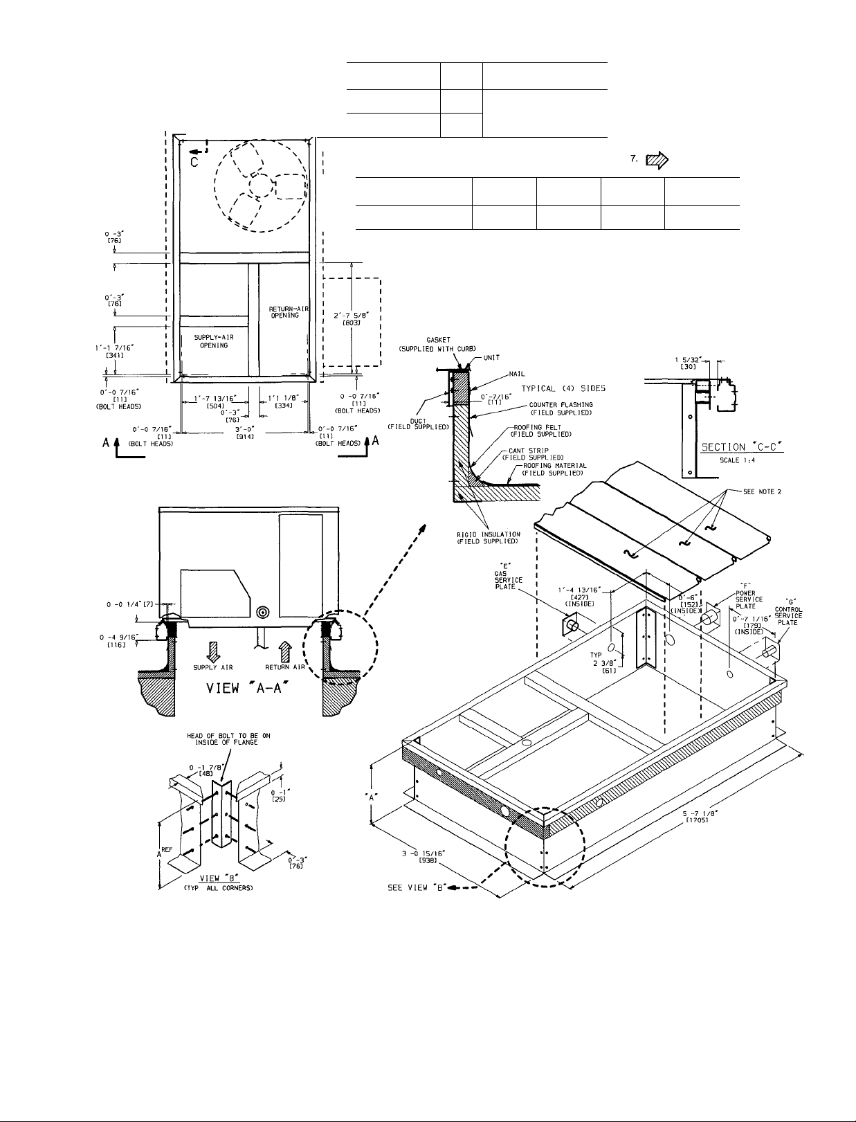
Step 3 — Install External Trap for Condensate
Drain — All units must have an external trap added for
condensate drainage. A y4-in. NPT connection is located
on the side of the unit. Use a trap at least 4-in. deep and
protect against freeze-up.
If drain line is run to a drain, pitch line away from unit at
1 in. per 10 ft of run. Do not use a pipe size smaller than
the unit connection. See Fig. 4 for more details.
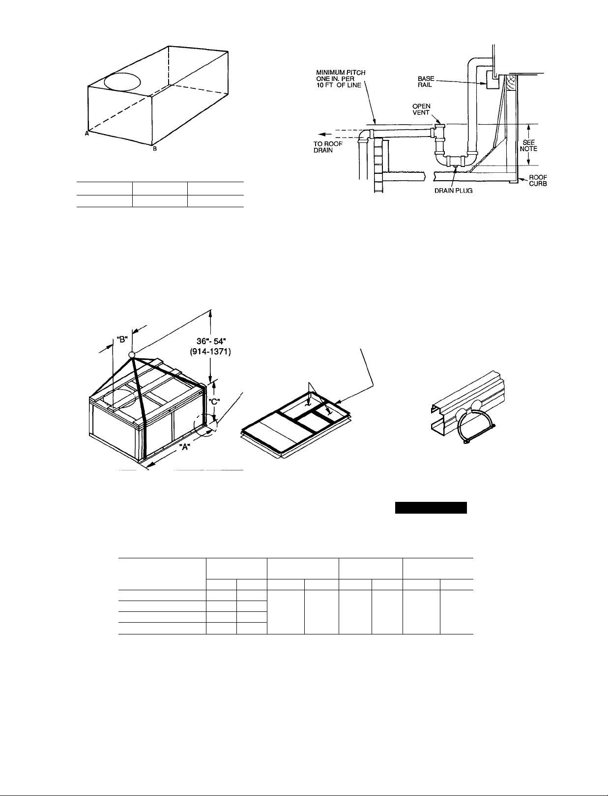
Step 4 — Rig and Place Unit — Inspect unit for
transportation damage. File any claim with transportation
agency. Keep unit upright and do not drop. Spreader bars
are not required if top crating is left on unit. Rollers may be
used to move unit across a roof. Level by using unit frame
as a reference. See Table 1 and Fig. 5 for additional infor
mation. Operating weight is shown in Table 1 and Fig. 5.
Lifting holes are provided in base rails as shown in
Fig. 6. Refer to rigging instructions on unit.
A CAUTION
I
______
POSITIONING — Maintain clearance around and above
unit to provide minimum distance from combustible mate
rials, proper airflow, and service access. See Fig. 6. A prop
All panels must be in place when rigging.
_________
erly positioned unit will have the following clearances
between unit and roof curb: 'A-in. clearance between roof
curb and base rails on each side and front of unit; U/32-in.
clearance between roof curb and rear of unit. (See Fig. 2,
section C-C.)
Do not install unit in an indoor location. Do not locate
unit air inlets near exhaust vents or other sources of con
taminated air.
Be sure that unit is installed such that snow will not block
the combustion intake or flue outlet.
Unit may be installed directly on wood flooring or on
Class A, B, or C roof-covering material when roof curb is
used.
Although unit is weatherproof, guard against water from
higher level runoff and overhangs.
Locate mechanical draft system flue assembly at least
48 in. from any opening through which combustion prod
ucts could enter the building, and at least 48 in. from an
adjacent building. When unit is located adjacent to public
walkways, flue assembly must be at least 7 ft above grade.
Flue vent discharge must have a minimum horizontal clear
ance of 4 ft from electric and gas meters, gas regulators,
and gas relief equipment.
Flue gas can deteriorate building materials. Orient unit
such that flue gas will not affect building materials.
Adequate combustion-air space must be provided for proper
operation of this equipment. Be sure that installation
complies with all local codes and Section 5.3, Air for Com
bustion and Ventilation, NFGC (National Fuel Gas Code),
|
ANSI (American National Standards Institute) Z223.1-
1984 and addendum Z223.la-1987. In Canada, instal
lation must be in accordance with the CAN LB 149.1 and
CAN1.B149.2 installation codes for gas burning
appliances.
Page 3
c
—!J------------------
—1
-------------------
ROOF CURB
ACCESSORY
50DJ900771
- 1
50DJ900781
A
1 '-2”
[356]
2"-0'
[610]
UNIT SIZE
48LJE/LJF004
48UD/LJE/UF005-007
NOTES:
1. Roof curb accessory is shipped
unassembled
2. Insulated panels.
3 Dimensions in [ ] are in millimeters
4. Roof Curb: galvanized steel
5 Attach ductwork to curb (Flanges of
duct rest on curb.)
6 Service clearance is 4 ft on each side.
Direction of airflow
UNIT SIZE
48LJE/LJF004
48LJD/LJE/LJF005-007
“E”
GAS
%" [19] NPT
“F”
POWER
%" [19] NPT 3/4" [19] NPT
“G”
CONTROL
CONNECTOR
PKG ACY
50DJ900791
Fig. 2 — Roof Curb Dimensions
Page 4
MAXIMUM ALLOWABLE
DIFFERENCE (in.)
/■
A-B
0.5 1.0 1.0
B-C
A-C
Fig. 3 — Unit Leveling Tolerances
NOTE: Trap should be deep enough to offset maximum unit static
difference, A 4-in. trap is recommended.
PLACE ALL SEAL STRIPS
IN PLACE BEFORE PLACING
UNIT ON ROOF CURB.
SEE DETAIL DUCT END
"A"
Fig. 4 — External Trap Condensate Drain
DETAIL "A"
NOTES:
1. Dimensions in ( ) are in miilimeters
2 Hook rigging shackles through holes in base rail, as shown in de
tail “A.” Holes in base rails are centered around the unit center of
gravity Use wooden top skid when rigging to prevent rigging straps
from damaging unit
MAX
UNIT
48LJE/LJF004 530 240
48LJD/LJE/LJF005 540 245
48LJD/LJE/LJF006
48LJD/LJE/LJF007 615 279
WEIGHT
Lb
560 254
Kg
Fig. 5 — Rigging Details
3 Unit weights do not include economizer. See Table 1 for
A B
in.
73.69
mm
1872
economizer weights.
All panels must be in place when rigging.
in.
35.5
mm in.
902
A CAUTION
C
mm
32.52 826
Page 5
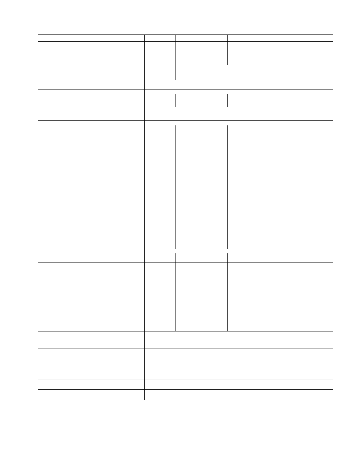
Table 1 — Physical Data
BASE UNIT 48
NOMINAL CAPACITY (tons)
OPERATING WEIGHT (lb)
Unit
Economizer
Roof Curb
COMPRESSOR
Quantity
Oil (oz)
REFRIGERANT TYPE
Operating Charge (Ib-oz) 6-0
CONDENSER FAN Propeiier Type
Quantity...Diameter (in.) 1 ..26.0
Nominal Cfm
Motor Hp...Rpm
CONDENSER COIL
Rows...Fins/in.
Total Face Area (sq ft)
EVAPORATOR FAN
Size (in.)
Type Drive
Nominal Cfm
Maximum Continuous Bhp
Motor Frame
Nominal Rpm High/Low
Fan Rpm Range
Motor Bearing Type
Maximum Fan Rpm
Motor Pulley Pitch Diameter A/B (in.)
Fan Pulley Pitch Diameter (in.)
Belt — Type...Length (in.)
Pulley Center Line Distance (in.)
Speed Change Per Full Turn of
Moveable Pulley Flange (rpm)
Movable Pulley Maximum Full Turns
From Closed Position
Factory Setting — Full Turns Open
Factory Speed Setting (rpm)
Fan Shaft Diameter at Pulley (in.) —
EVAPORATOR COIL
Rows...Fins/in.
Total Face Area (sq ft)
FURNACE SECTION
Burner Orifice Diameter (in. ...drill size)*
Natural Gas — Std
Liquid Propane — Alt
Thermostat Heat Anticipator Setting (amps)
208/230/460 V
First Stage
Second Stage
Gas Input
First Stage
Second Stage
Efficiency (Steady State) (%)
Temperature Rise Range
Manifold Pressure (in. wg)
Natural Gas — Std
Liquid Propane — Alt
Field Gas Connection Size (in.)
HIGH-PRESSURE SWITCH (psig)t
Standard Compressor Internal Relief
Cutout
Reset (Auto.)
LOSS-OF-CHARGE/LOW-PRESSURE SWITCHf
(liquid Line) (psig)
Cutout
Reset (Auto.)
FREEZE PROTECTION THERMOSTATf
Opens (F)
Closes (F)
OUTDOOR-AIR INLET SCREENS
Qty...Size (in.)
RETURN-AIR FILTERS
Qty...Size (in.)
Std
Alt Direct
Std
Alt 81
Std
Alt 48
Std
Ait 1080/970
Std
Alt
Std
Alt
Std
Alt
Std
Alt
Std
Alt
Std
Alt
Std
Alt
Std — —
Alt
std — —
Alt
LJE/LJF004
3
530
34
115
Reciprocating
1
55
4600
Уз 850
1.. 17
12 25
10 X 10
Direct
1200
34
48
860/845
—
—
Baii
2100
—
—
— —
—
—
—
—
—
— —
—
—
—
—
—
2. 15 2.. 15
4 17 55 55
113 33
089 43
.14
-/14
74,000/82,000
-/115,000
80
25-55/55-85
35
3.5
.5
LEGEND
Bhp — Brake Horsepower
*The 48LJD005-007 and 48LJE004 (74,000 Btuh) units have 2 burners The 48LJE005-007 and 48LJF004 (115,000 Btuh) units and
the 48LJF005-007 (150,000 Btuh) units have 3 burners
flndioates a FlOP (Factory-instalied Option) that requires a control kit.
LJD/LJE/LJF005
4
540
34
115 115
LJD/LJE/LJF006
560 615
Scroil
1 1
55
7-6 8-3 9-12
1 ..26.0 1...26.0
4600
Уз...850
Enhanced Copper Tubes, Aiuminum Lanced Fins
2.. 17
12.25
10 X 10
Direct
Beit
1600
.81
1 20
48
56
1080/970
—
_
970-1310
Bali
2100
—
1 9/2 9
3.5
— A 39
A 31
—
14 7-15 5
68
—
5
3
1110
5/8 У2
Enhanced Copper Tubes, Aluminum Doubie Wavy Fins, Acutroi'“ Feed Device
113. 33/113 33/129 30 113. 33/113 33/129. 30
.089.. 43/089 .43/.102 .38 089 43/089 43/102 38
.14 14
-/-/14
74,000/115,000/120,000 74,000/115,000/120,000
-/-/150,000
80 80
25-55/35-65/50-80
35
3.5
.5
R-22
Centrifugai Type
-/-/150,000
25-55/35-65/50-80
625
428
320
7 ± 3
22 ± 7
30 ± 5
45 ± 5
Cieanabie
1
..20 X 24 X 1
Throwaway
2.. 16 X 25 X 2
4100
У3...850 Уз . 850
2.. 17 2.. 17
12.25
10 X 10
Beit
2000
1 80
900-1300
Baii Bail
2100
2 4/3 4
14 7-15.5
1060 1230
3.. 15 4...15
-/-/14
5 6
34 34
115
Reciprocating
LJD/LJE/LJF007
70 65
1 . 26.0
4i00
12.25
10 X 10
— —
—
56
—
—
—
—
—
4.5 45
— —
— —
— —
80
—
5
_
3 3
— —
Beit
2400
2 40
1070-1460
2100
2.8/3.8
A 39
14 7-15 5
—
113 33/113 33/.129.30
089 43/089 43/102 38
-/-/14
74,000/115,000/120,000
-/-/150,000
25-55/35-65/50-80
35
3.5 3.5
.5 .5
—
56
—
—
—
—
79
—
—
Ув
5.5
3.5
1
—
5
14
80
Page 6
STD UNIT
UNIT
48LJE/LJF004 530
48LJD/LJE/UF005 540
48UD/UE/UF006
48UD/UE/UF007 615 279
WEIGHT
Lb
560
Kg
240
245
254
ECONOMIZER
WEIGHT
Lb
Kg
34
15.4
34 15.4
34 154 110
34 154 120
CORNER
WEIGHT (A)
Lb
Kg
104
47.2 97
106 48 1
49.9
54.4
CORNER
WEIGHT (B)
Lb
Kg
44.0
98 44.5
102 46 3
112 50.8
RIGHT SIDE
'Indicates horizontal center of gravity
flndicates vertical center of gravity
NOTES:
1. Dimensions in [ ] are in millimeters.
Center of Gravity.
3 Direction of airflow
4. On vertical discharge units, ductwork is to be
attached to accessoiy roof curb only. For hor
izontal discharge units, field-supplied flanges
should be attached to horizontal discharge
openings and all ductwork should be at
tached to the flanges.
5 Minimum clearances are as follows (local codes
or jurisdiction may prevail):
NOTE: When installing these units, use the
maximum clearance stated for your application
a Between unit, flue side, and combustible
surfaces, 36 inches. (Minimum clearance
to combustibles, flue side, is 18 in for units
with accessory flue discharge deflector.)
b. Bottom to combustible surfaces (when not
using curb), 0 in. for LJD,LJE units and
1 in. for LJF units.
c. Condenser coil for proper airflow, 36-in one
side, 12 in the other The side getting the
greater clearance is optional
d. Overhead, 60 in to assure proper con
denser fan operation
e. Horizontal supply and return end, 0 inches
f Between units, control box side, 42 in per
NEC (National Electrical Code),
g Between unit and ungrounded surfaces, con
trol box side, 36 in. per NEC.
h. Between unit and block or concrete walls
and other grounded surfaces, control box
side, 42 in. per NEC.
6. With the exception of the clearance for the
condenser coil and combustion side, as stated
in Notes 5a, b, and c, a removable fence or
barricade requires no clearance
7 Units may be instailed on combustible floors
made from wood or class A, B, or C roof cov
ering material
UNIT
48LJE/LJF004
48LJD/LJE/LJF005 162
48LJD/LJE/LJF006 168
48LJD/LJE/LJF007
WEIGHT (C)
Lb
159
185
FRONT
CORNER
Kg
72.1 171
73.5 174 78.9
76.2
83.9 198
CORNER
WEIGHT (D)
Lb
77.6
81.6
180
89.8
Kg
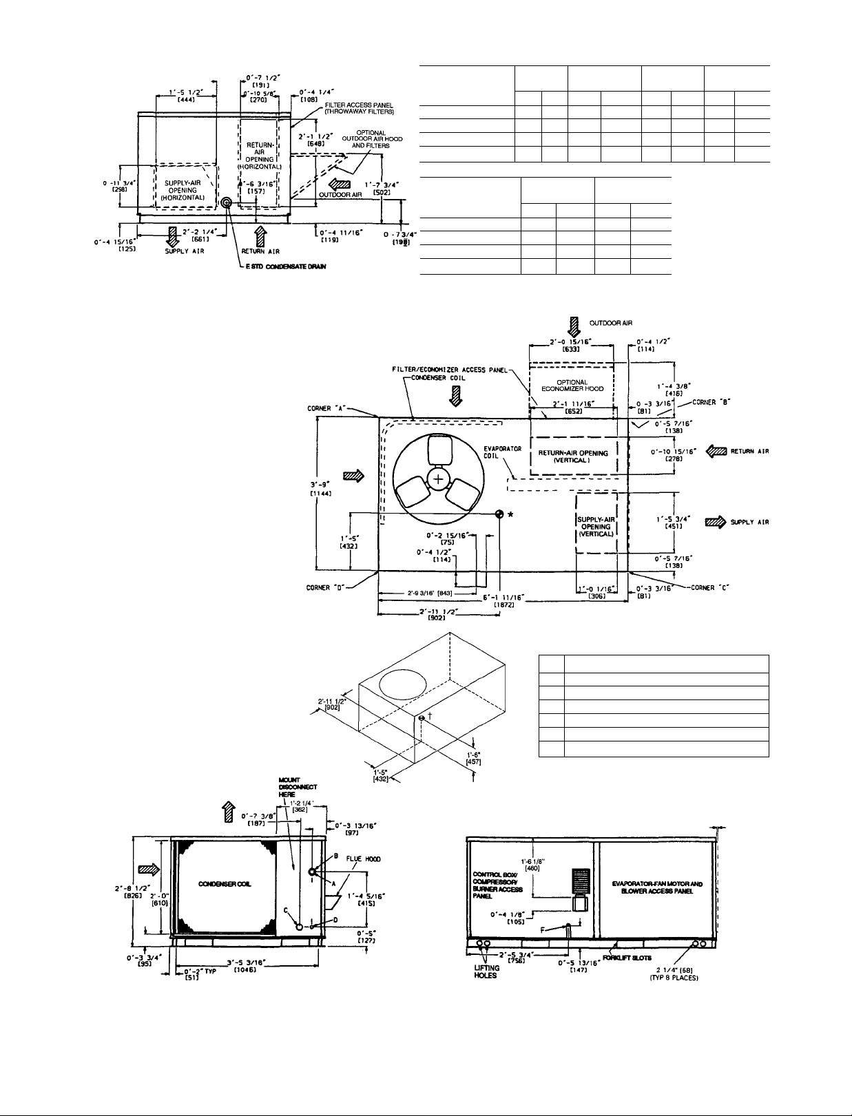
Connection Sizes
1%" Dia [351 Field Power Supply Hole
A
2" Dia [50.51 Power Supply Knockout
B
2¥i6" Dia [551 Charging-Port Hole
c
%" [221 Field Control Wiring Hole
D
%" Condensate Drain
E
V2"-14 NPT Gas Connection
F
LEFT SIDE
Fig. 6 — Base Unit Dimensions
FRONT
O'-O 3/B
r’OJ
L
Page 7
i'
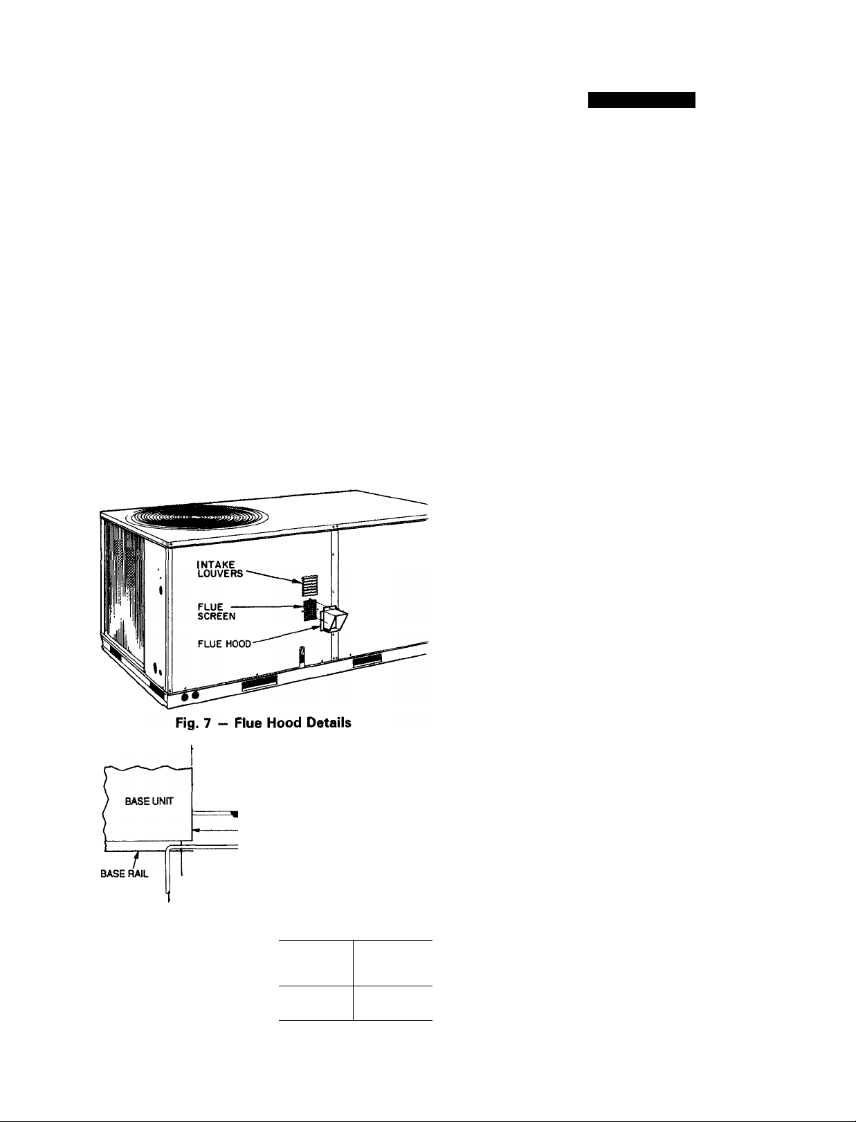
Step 5 — Install Flue Hood — Flue hood and screen
are shipped screwed to the burner compartment access panel.
Remove from shipping location and using screws provided,
install flue hood and screen in location shown in Fig. 7.
Step 6 — Install Gas Piping — Unit is equipped for
use with type of gas shown on nameplate. Refer to local
building codes, or in the absence of local codes, to ANSI
Z223.1-1984 and addendum Z223-1A-1987 entitled Na
tional Fuel Gas Code. In Canada, installation must be in
accordance with the CANl.B 149.1 and CAN1.B149.2 in
stallation codes for gas burning appliances.
For natural gas applications, gas pressure at unit gas con
nection must not be less than 4 in. wg or greater than
13.0 in. wg while unit is operating. On 48LJ005,006,007
high heat units, the gas pressure at unit gas connection must
not be less than 5 in. wg or greater than 13 in. wg while the
unit is operating. For propane applications, the gas pressure
must not be less than 5 in. wg or greater than 13 in. wg at
the unit connection.
Size gas supply piping for 0.5 in. wg maximum pressure
drop. Do not use supply pipe smaller than unit gas connec
tion. Support gas piping as shown in the table in Fig. 8. For
example, a %-in. gas pipe must have one field-fabricated
support beam every 8 ft. Therefore, an 18-ft long gas pipe
would have a minimum of 2 support beams, a 48-ft long
pipe would have a minimum of 6 support beams.
See Fig. 8 for typical pipe guide and locations of exter
nal manual main shutoff valve.
9” MINIMUM CLEARANCE
FOR PANEL REMOVAL
MANUAL GAS GAS
I SHUTOFF VALVE* REGUUTOR*
48" MINIMUM -
DRIP LEG PER NFGC
ROOF CURB
FROM GAS METER
LEGEND
NFGC — National Fuel Gas Code
"Field supplied.
NOTE: Follow all local codes
FIELD-FABRICATED*
SUPPORT
SPACING OF SUPPORTS
STEEL PIPE
NOMINAL
DIAMETER
(In.)
%
*/4 or 1 8
1’/4 or larger 10
Fig. 8 — Gas Piping Guide (With Accessory
Thru-the-Curb Service Connections)
7
X
DIMENSIONS
(feet)
6
Step 7 — Make Electrical Connections
A WARNING
Unit cabinet must have an uninterrupted, unbroken elec
trical ground to minimize the possibility of personal in
jury if an electrical fault should occur. This ground may
consist of electrical wire connected to unit ground lug
in control compartment, or conduit approved for elec
trical ground when installed in accordance with NEC
(National Electrical Code), ANSI/NFPA (National Fire
Protection Association), latest edition, and local elec
trical codes. Do not use gas piping as an electrical ground.
Failure to follow this warning could result in the in
staller being liable for personal injury of others.
FIELD POWER SUPPLY - All units except 208/230-v
units are factory wired for the voltage shown on the name
plate. If the 208/230-v unit is to be connected to a 208-v
power supply, the transformer must be rewired by moving
the black wire from the 230-v orange wire on the trans
former and connecting it to the 200-v red wire from
the transformer. The end of the orange wire must then be
insulated.
Refer to unit label diagram for additional information.
Wiring leads are provided for field service. Use copper con
ductors only when splice connectors are used.
When installing units, provide a disconnect per NEC.
All field wiring must comply with NEC and local require
ments. In Canada, electrical connections must be in accor
dance with CSA (Canadian Standards Association) C22.1
Canadian Electrical Code Part 1.
Install conduit through side panel openings indicated in
Fig. 6. Route power lines through connector to terminal
connections as shown in Fig. 9.
Voltage to compressor terminals during operation must
be within voltage range indicated on unit nameplate (also
see Table 2). On 3-phase units, voltages between phases
must be balanced within 2% and the current within 10%.
Use the formula shown in the legend for Table 2, Note 2 to
determine the percent voltage imbalance. Operation on im
proper line voltage or excessive phase imbalance consti
tutes abuse and may cause damage to electrical components.
Such operation would invalidate any applicable Carrier
warranty.
FIELD CONTROL WIRING - Install a Carrier-approved
accessory thermostat assembly according to installation in
structions included with the accessory. Locate thermostat
assembly on a solid wall in the conditioned space to sense
average temperature in accordance with thermostat instal
lation instmctions. Connect thermostat wires to terminal board.
Route thermostat cable or equivalent single leads of col
ored wire from subbase terminals through connector on unit
to low-voltage connections (shown in Fig. 10).
Connect thermostat wires to matching screw terminals of
low-voltage connection board. See Fig. 10.
NOTE; For wire runs up 50 ft, use no. 18 AWG (American
Wire Gage) insulated wire (35 C minimum). For 50 to
75 ft, use no. 16 AWG insulated wire (35 C minimum).
For over 75 ft, use no. 14 AWG insulated wire (35 C min
imum). All wire larger than no. 18 AWG cannot be directly
connected to the thermostat and will require a junction box
and splice at the thermostat.
Pass the control wires through the hole provided in the
end panel; then feed wires through the raceway built into
the comer post to the 24-v barrier located on the left side of
the control box. See Fig. 11. The barrier provides the UL
(Underwriters’ Laboratories) required clearance between highand low-voltage wiring.
Page 8
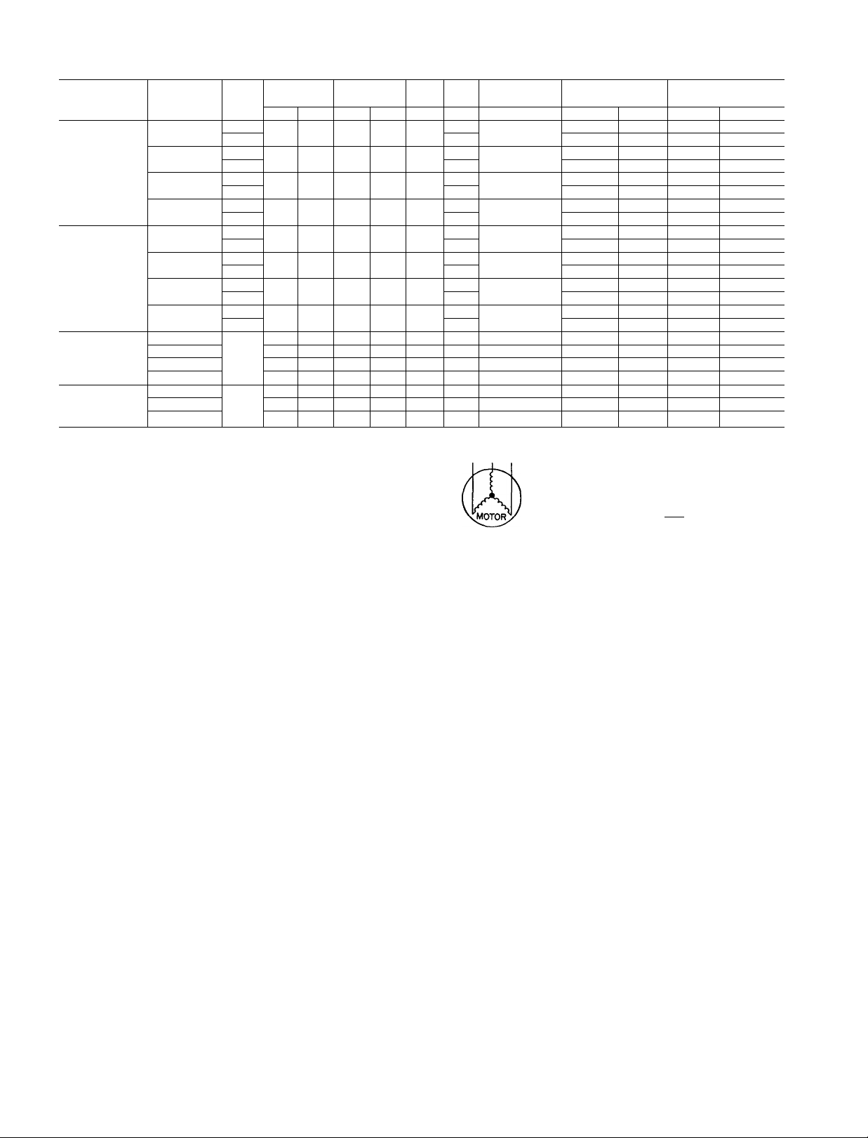
Table 2 — Electrical Data
VOLTAGE
UNIT
48LJE/LJF004
(3 Tons)
48LJD/LJE/LJF
005
(4 Tons)
48LJD/LJE/LJF
006
(5 Tons)
48LJD/LJE/LJF
007
(6 Tons)
IMPORTANT: Optional, alternate evaporator-fan motor and drive are not
available for 48LJ006,007 units. Contact your local Carrier representative
for more information about field-installed motors
COMPR
FLA
HACR
IFM
LRA
MCA
MOCP
OFM
RLA
*Fuse or HACR circuit breaker
NOTES:
1. In compliance with NEC (National Electrical Code) requirements for multi
motor and combination load equipment (refer to NEC Articles 430 and 440),
the overcurrent protective device for the unit shali be fuse or HACR breaker
Canadian Standards Association (CSA) units may be fuse or circuit breaker
2 Unbalanced 3-Phase Supply Voltage
Never operate a motor where a phase imbalanoe in supply voltage is greater
than 2% Use the following formula to determine the percent voltage im
balance.
% Voltage Imbalance
100 X
NOMINAL
V-PH-HZ
208/230-1-60
208/230-3-60
460-3-60
575-3-60
208/230-1-60
208/230-3-60
460-3-60
575-3-60
230-1-60
208/230-3-60
460-3-60
575-3-60
208/230-3-60
460-3-60
575-3-60
LEGEND
Compressor
Full Load Amps
Heating, Air Conditioning and Refrigeration
Indoor (Evaporator) Fan Motor
Locked Rotor Amps
Minimum Circuit Amps
Maximum Overcurrent Protection
Outdoor (Condenser) Fan Motor
Rated Load Amps
max voltage deviation from average voltage
average voltage
IFM
TYPE
Std
Alt 3.8 28.1/28 1
Std
Alt 38
Std
Alt 1.9 105
Std
Alt
Std
Alt 57 38.6/38 6
Std
Alt
Std
Alt 2.8 13.5
Std
Alt
Std
Std
RANGE
Min Max RLA
187 254 179
187 254 11 2
414
508
632 45
518
187 254 24 8
187 254 157
414
508 78
632 55
518
187 254 27.8
187
254
414 508 96
518 632 83
187 254 21 9
414 508
518 632 96
COMPR
(each)
6 1
19.2
104
OFM
LRA FLA FLA FLA
93 1 9
80 1 9
40 1 0
29 1 9
127 1 9
99 1.9
50 1 0
40 1.9
135 1 9 85 .57
105 1 9
55 1 0
45 1 9
142 1 9 5.8 57 35.1/35.1
72
1 0
58 5 1 9
11 0
FAN MOTOR
2.8
28
1 5
2.8
38 7.9
38
3.8
5.7 27 2/27.2
1 9
38
5.7 9.9
8.5 .57
4.5
85
2.6
Example: Supply voltage is 460-3-60.
ABC BC = 464v
NOTE: The 575-v units are CSA only
Determine maximum deviation from average voltage
(AB) 457 - 452 = 5 V
(BC) 464 - 457 = 7 V
(AC) 457 - 455 = 2 V
Maximum deviation is 7 v.
Determine % voltage imbalance
% Voltage Imbalance = 100 x
This amount of phase imbalance is satisfactory as it is below the maximum
allowable 2%
IMPORTANT: If the supply voltage phase imbalance is more than 2%,
contact your local electric utility company immediately
57
.57
30
57
57
57
.30
57
30
.57
30
57
COMBUSTION
IFM
POWER SUPPLY
MCA
27 1/27 1
18 7/18.7 25/25 18/18
19 7/19.7
101
7.5
36 7/36.7
25 3/25.3
126
9.2
45 2 60
34.4/34.4 40/40 34/34
17.5
14.5
16.6
172
AB = 452V
AC = 455V
Average Voltage
-----------
= 1 53%
DISCONNECT SIZE
MOCP* FLA
35/35
35/35 27/27
25/25 19/19
15
15 10
15 7
15
45/45
45/45 37/37
30/30 25/25 113/113
35/35 27/27 116/116
15
26/26
10
8
35/35
12
20 13
15
15
9
10
44 164
20 17 81
20 14
40/40 34/34 188/188
20 16
20 17 81
452 4- 464 4- 455
_ 1371
3
= 457
7
457
LRA
105/105
107/107
92/92
94/94
46
46
34
34
141/141
144/144
56
58
45
47
134/134
57
95
Page 9
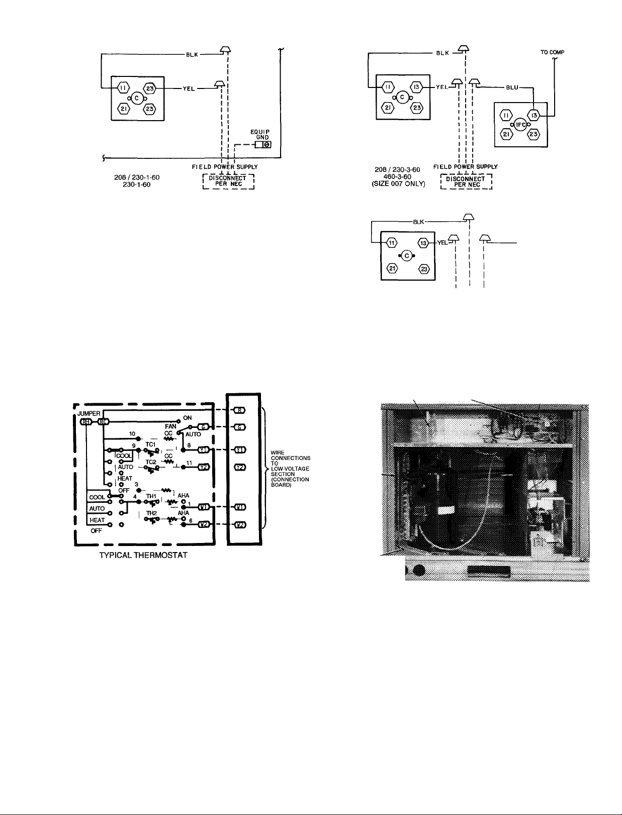
c
COMP
EQUIP
GND
IFC
NEC
LEGEND
Contactor
Compressor
Equipment
Ground
Indoor (Evaporator) Fan Contactor
National Electrical Code
TO
c
Fig. 9 — Power Wiring Connections
LEGEND
AHA
CC
TC
NOTE: Connect Y2 when unit is equipped with an economizer.
Adjustable Heat
Anticipator
Cooling Compensator
Thermostat-Cooling
TH — Thermostat-Heating
---------
Field Wiring
----------
Factory Wiring
Fig. 10 - Low-Voitage Connections
208 / 230-3-60
460-3-60
(SIZES 004-006)
575-3-60
(SIZES 004-007)
CONNECTION BOARD LED
RACEWAY
HOLE
IN
END
PANEL--(HIDDENV
LED — Light-Emitting Diode
FIELD POWER SUPPLY
Fig. 11 — Fieid Control Wiring Raceway
DISCONNECT
PER NEC
INTEGRATED GAS UNIT
CONTROLLER (IGC)
Page 10
HEAT ANTICIPATOR SETTINGS - Set heat anticipator
settings at. 14 amp for the first stage and . 14 amp for secondstage heating, when available.
Step 8 - Make Outdoor-Air Adjustments and Install Outdoor-Air Hood
MANUAL OUTDOOR-AIR DAMPER - The outdoor-air
hood and screen are attached to the basepan at the bottom
of the unit for shipping.
Assembly:
1. Determine quantity of ventilation required for building.
Record amount for use in Step 8.
2. Remove and save evaporator coil access panel and screws.
See Fig. 12.
3. Separate hood and screen from basepan by removing the
4 screws securing them. Save all screws.
EVAPORATOR
COIL ACCESS ?
PANEL \
SCREWS
(SIDE) “
4. Replace evaporator coil access panel.
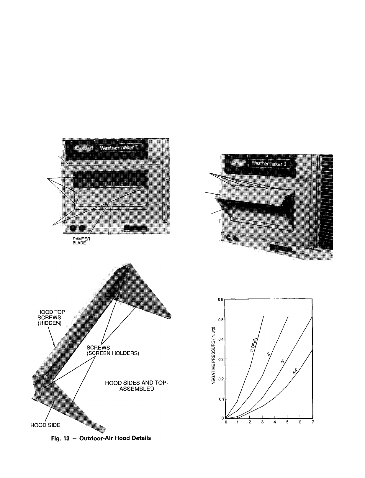
5. Place hood on front of evaporator coil access panel. See
Fig. 13 for hood details. Secure top of hood with the 4
screws removed in Step 3. See Fig. 14.
6. Remove and save 6 screws (3 on each side) from sides
of the manual outdoor-air damper.
7. Align screw holes on hood with screw holes on side of
manual outdoor-air damper. See Fig. 13 and 14. Secure
hood with 6 screws from Step 6.
8. Adjust minimum position setting of the damper blade by
adjusting the manual outdoor air adjustment screws on
the front of the damper blade. See Fig. 12. Slide blade
vertically until it is in the appropriate position deter
mined by Fig. 15. Tighten screws.
9. Remove and save screws currently on sides of hood. In
sert screen. Secure screen to hood using the screws. See
Fig. 14.
SCREW
HOLES
(TOP)
HOOD
MANUAL
OUTDOOR-AIR »
ADJUSTMENT
SCREWS
POSITION
SETTING SCALE
Fig. 12 — Damper Panel with Manual Outdoor-Air
Damper Installed
HOOD
SCREEN
LOCATION
(SCREEN NO
SHOWN)
Fig. 14
Outdoor-Air Damper with Hood
Attached
OUTDOOR AIRFLOW (cfm x 100)
Fig. 15 - Position Setting
10
Page 11

TWO-POSITION DAMPER - The outdoor-air hood and
screen are attached to the basepan at the bottom of the unit.
Assembly:
1. Determine quantity of ventilation air required for build
ing. Record amount of air for use in Step 9.
2. Remove and save evaporator coil access panel and screws.
See Fig. 16.
3. Separate hood from basepan by removing the 4 screws
securing the hood. Save screws.
4. Insert two-position damper plug from wiring harness
(supplied with the unit) into the wiring harness (sup
plied with the two-position damper).
5. Replace evaporator coil access panel.
6. Place hood on front of evaporator coil access panel.
See Fig. 13 for hood details. Secure top of hood with
the 4 screws removed in Step 3. See Fig. 14.
EVAPORATOR
COIL ACCESS
PANEL
SCREW
HOLES
(SIDE)
EVAPORATOR
COIL ACCESS
PANEL
BLOCK-OFF
PANEL
------
'
mm
Fig. 17 — Access Panel Location
i
OUTDOOR-AIR
ADJUSTMENT
SCREWS
POSITION
SETTING SCALE
Fig. 16 — Damper Panel with Two-Position
Damper Installed
7. Remove and save 6 screws (3 on each side) from sides
of the two-position damper.
8. Align screw holes on hood with screw holes on side of
two-position damper. See Fig. 13 and 14. Secure hood
with 6 screws from Step 7.
9. Determine two-position damper setting by using
Fig. 15. Set the damper panel position using the air ad
justment screws. See Fig. 16. Tighten screws.
10. Remove and save 4 screws currently on sides of hood.
Insert screen. Secure screen to hood using the 4 screws.
See Fig. 14.
OPTIONAL ECONOMIZER — The economizer hood as
sembly is packaged and shipped in the filter section. Damper
blades are installed at the factory and the economizer is shipped
in the vertical position.
Assembly:
1. Determine quantity of ventilation air required for build
ing. Record amount of air for use in Step 8.
2. Remove evaporator coil access panel (see Fig. 17). Save
panel and screws.
3. Assemble outdoor-air hood top and side plates as shown
in Fig. 18. Install seal strips on hood top and sides. Put
aside screen retainer and screws for later assembly. Do
not attach hood to unit at this time.
4. The block-off panel should be removed from the evap
orator coil access panel and discarded. Save screws.
See Fig. 17.
HOOD SIDES AND TOP ASSEMBLED
Fig. 18 — Outdoor-Air Hood Details
5. Remove screws securing barometric relief damper, if
desired. See Fig. 19.
6. To convert to horizontal discharge application:
a. Remove filters from filter track.
IMPORTANT: Filters must be installed outside the
unit on horizontal discharge applications with econo
mizer. Otherwise, economizer must be partially re
moved to access the filters. The area of the fieldinstalled filters should be equal to the area of the factoryinstalled filters.
Rotate economizer 90 degrees until economizer mo
b.
tor faces condenser section (see Fig. 20). If neces
sary, disassemble economizer to replace filter.
Rotate barometric relief damper 90 degrees so that it
c.
opens and closes vertically.
11
Page 12

d. Install horizontal discharge block-off plate over
opening on the access panel. Block-off plate
MUST be installed before installing hood assembly
(see Fig. 21).
NOTE: Install spacers at the same time as the hori
zontal block-off plate using same screws. The spac
ers are used to cover gaps between the economizer
assembly and the unit.
ECONOMIZER
WIRE
HARNESS
PLUGS
BAROMETRI!
RELIEF
DAMPER^
Fig. 19 — Economizer Installed in Unit
BLOCK-OFF PLATE
Fig. 21 — Horizontal Discharge Block-Off Plate
7. Insert economizer plug from the wiring harness (sup
plied with the unit) into the wiring harness plug (sup
plied with the economizer). See Fig. 19.
8. Determine economizer damper position setting (see
Fig. 22). Adjust damper setting by adjusting screws on
the position setting bracket (see Fig. 23). Slide posi
tion setting bracket until top screw (see Fig. 23) is in
the position determined by Fig. 22. Tighten screws.
9. Install evaporator coil access panel with screws saved
from Step 2.
10. Fasten hood top and side plate assembly to unit with
screws saved from the block-off panel removal (see
Fig. 18).
11. Remove tape from outdoor-air thermostat (OAT). Fas
ten OAT to inside of hood using screws and speed clips
provided (see Fig. 24). Make sure OAT terminals are
up.
12. Place knob, supplied with economizer, on OAT. Set it
for 3 F below indoor room thermostat setting. If ac
cessory solid-state enthalpy control (EC) is used in
stead of the OAT, see instructions shipped with EC for
installation and adjustment (see Fig. 24).
13. Connect OAT per Fig. 25.
14. Slide outdoor-air inlet screens into screen track on hood
side plates. While holding screens in place, fasten screen
retainer to hood using screws provided.
15. Turn on base unit power.
BAROMETRIC
RELIEF DAMPER
Fig. 20 — Horizontal Economizer Installation
(90 Degree Rotation)
12
Page 13

Example:
Given —
Return-Air Negative Static Pressure .........................0 2 in wg
Outdoor Air
Determine —
Setting = 5
Fig. 22 — Economizer Damper Minimum Position Setting
Fig. 23 - Minimum Position Damper Setting
OUTDOOR AIRFLOW (cfm x 100)
......................................................
Step 9 — Adjust Evaporator-Fan Speed — Ad
just evaporator-fan speed to meet jobsite conditions.
Table 3 shows fan rpm at motor pulley settings. Refer to
Tables 4-15 to determine fan speed settings.
DIRECT DRIVE MOTORS — The evaporator-fan motor
factory speed setting is shown on label diagram affixed to
base unit. If other than factory setting is desired, refer to
label diagram for motor reconnection.
BELT DRIVE MOTORS — Ean motor pulleys are factory
set for speed shown in Table 1.
NOTE: Before adjusting fan speed, make sure the new fan
speed will provide an air temperature rise range as shown
in Table 1.
To change fan speed:
1. Shut off unit power supply.
2. Loosen belt by loosening fan motor mounting nuts. See
Fig. 26.
3. Loosen movable pulley flange setscrew (see Fig. 27).
4. Screw movable flange toward fixed flange to increase
speed and away from fixed flange to decrease speed. In
creasing fan speed increases load on motor. Do not ex
ceed maximum speed specified in Table 1.
5. Set movable flange at nearest key way of pulley hub and
tighten setscrew. (See Table 1 for speed change for each
full turn of pulley flange.)
900 cfm
13
Page 14

OR ACCESSORY
ENTHALPY
CONTROL
GRAY
---------------
OAT
---------------------------------------
Fig. 25 — Wiring Connections for
Outdoor-Air Thermostat
■i\fcTOR MOUNTffviS
ieiATe NUTSJ
ASSvAvA'A'Mv.
ORANGE-
HOOD.
"ERMWALS
bUTOObR-AiRTHERMOStATl
(TERMiNAl-S ARE UP) ,; |
iii
Fig. 24 — Outdoor-Air Thermostat/
Enthalpy Control Installation
\
HOOD
Fig. 26 - Belt Drive Motor Mounting
Fig. 27 — Evaporator-Fan Pulley Adjustment
To align fan and motor pulleys:
1. Loosen fan pulley setscrews.
2. Slide fan pulley along fan shaft.
3. Make angular alignment by loosening motor from
mounting.
To adjust belt tension:
1. Loosen fan motor mounting nuts.
2. Slide motor mounting plate away from fan scroll for proper
belt tension ('/2-in. deflection with one finger).
3. Tighten motor mounting nuts.
4. Adjust bolt and tighten nut to secure motor in fixed
position.
14
Page 15

Table 3 — Fan Rpm at Motor Pulley Settings
UNIT
48LJD/LJE
005* 1310
006
007 1460
0
1300
'Indicates alternate motor.
Table 4 — Fan Performance, 48LJE/LJF004 Vertical
AIRFLOW
(Cfm)
900
1000
1100
1200
1300
1400
1500
LEGEND
Bhp — Brake Horsepower
ESP — External Static Pressure
NOTE: Values Include losses for filters, unit casing, and wet coils.
MOTOR PULLEY TURNS OPEN
Va 1
1285 1245
1260 1220
1420 1380
IVa
1210
1180
1340
2
2Va
1175 1140
1140
1100
1300
1265
3
1110
1060
1230
3Va
1075
1020
1190
Discharge Units; Standard Motor (Direct)
LOW SPEED HIGH SPEED
208
ESP
0 46 0.17
0.44
0.40
0 32
0.28 0.24
0.22
0 16 0 27 0 18
230, 460, 575 208
Bhp
0.20 0.45
0.21
0.23
ESP Bhp
0 48 0.19 0.49 0.21 0.51
0.42 0.24
0 37 0.25
0 32 0.26
0.26 0 25
ESP
0.22
0.47 0.23 0.48
0.44 0.25 0.45
0.38 0.27 0.40
0.32 0.29 0.34
0.28
0.26 0.30 0.28
0.33
0.20 0.31 0.21
Bhp
4
1005 970
1040
980 940 900
1110
1150
230, 460, 575
ESP
Bhp
0.25
0.27
0.29
0.31
0.32
0.33
0.34
4Va
5
1070
Table 5 — Fan Performance, 48LJE/LJF004 — Vertical
Discharge Units; Alternate Motor (Direct)
AIRFLOW
(Cfm)
900
1000
1100
1200
1300
1400
1500
ESP Bhp ESP
0.77
0.70 0 38
0.25 0.53 0 33
LEGEND
Bhp — Brake Horsepower
ESP — External Static Pressure
NOTE: Values include losses for filters, unit casing, and wet coils.
LOW SPEED HIGH SPEED
208 230, 460, 575 208 230, 460, 575
0.83 0 38 0.97 0.48 1.09 0.60
0.36
0.62
0 53 0.44 0.58
0 44
0.35 0.50
0 75
0 66 0.45 0.80 0 53 0.92
0.41
0 48 0.50
0 42
Bhp
0 41
0 48 0.72 0.56 0 84 0 65
0.50 0.64 0.60 0.75 0.68
0.54
0.58 0.47 0.65
Bhp
ESP
0.89 0 51 1.01
0.63 0 67 0 69
0.56
ESP
0.58
Bhp
0.62
0 64
0 72
15
Page 16

Table 6 — Fan Performance, 48LJD/LJE/LJF005 Vertical Discharge
Units; Standard Motor (Direct)
AIRFLOW
(Cfm)
1200
1300
1400
1500
1600
1700
1800
1900
2000
Bhp — Brake Horsepower
ESP — External Static Pressure
NOTE: Values include losses for filters, unit casing, and wet coils.
0.53
LEGEND
LOW SPEED
208
ESP Bhp
0.44
0 44
0,48
0.35
0.50
0.25
0 53 0 33
0.16 0 57
0.09
0 58
0 00
0.61
_
—
—
—
230, 460, 575
ESP
0 58
0.50
0 42
0 24
0 15
0 06
Bhp ESP Bhp ESP
0 48
0.50
0.54 0 56 0 63
0.58
0 60
0 63
0 65
— —
— —
HIGH SPEED
0.56
0.60
0 65
0 69
0 73
230, 460, 575
Bhp
0.84
0.75 0.68
0.67 0.69
0.58 0 72
0 50 0.74
0 40
0.32
0.24
0 65
0.76
0.78
0.79
208
0 72
0 64
0.47
0 38 0 68
0 30
0.22 0 71
0.12
0.03 0.74 0.15 0.81
Table 7 — Fan Performance, 48LJD/LJE/LJF005 Vertical Discharge Units; Alternate Motor (Belt)
AIRFLOW
(Cfm)
1200 701 0.22 758
1300
1400
1500 836
1600
1700 925 0.55 981
1800
1900 1011
2000 1058 0 81 1100
Bhp — Brake Horsepower
NOTES:
1. Boldface indicates field-supplied drive required. (See Note 5.)
2 indicates field-supplied motor and drive required
3 Maximum usable bhp is 1.2. Extensive motor and electrical test
ing on these units ensures that the full horsepower range of the
0.1
Rpm Bhp Rpm Bhp
747
0.27 800 0.34
792
0.33
0.39
0.47
881
964
0.63
0.73
LEGEND
02
0.28
847
0.40
897
0.46
0.54
945
0.61
1024
0.72
1068 0.79
0.85
1 0.3 1
Rpm Bhp
834
865
901 0.47
947 0.55
983
1020 0.68
1084 0 75
1120
1160
EXTERNAL STATIC PRESSURE (in. wg)
1 0.4
Rpm Bhp
0.35 914 0.42
0.41
945 0.52
960 0.56
1000 0.61 1132
0 62
1065 0.67 1172
1103 0 72 1202 0 88
1140 0.82
0.82
1172
0 90
1237
1 0.6 1
Rpm
1012
1050
1091
1230
0 91 1256
1 20
Bhp
0 56
0 62
0.67
0 72
0.77
0 97
1,18
motor can be utilized with confidence Using your fan motors up
to the horsepower ratings shown will not result in nuisance
tripping or premature motor failure. Unit warranty will not be affected.
Values include losses for filters, unit casing, and wet coils
Alternate motor drive range: 970 to 1310 rpm. All other rpms re
quire field-supplied drive
Use of field-supplied motor may affect wire sizing Contact Car
rier representative to verify.
1 0.7 1 08
Bhp Rpm
Rpm
1056 0.59 1098
0 63 1132 0 68
1090
1130 0.70
1170
1207 0.86 1238
1243
1268
,.1,13:3
1310
1165
0.75 1205
0 98 1270 1 1.05 1350 1.16
1 07
1300!
Bhp Rpm Bhp
0.62 1180 0 68 1255 0.76
0.72 1242 0.82
0 82 1275 0 91 1330 0.98
0 92 1310 1.05 1350 1.08
1.15
L 1.0
____
1212 0.72
1 1-2
1
Rpm Bhp
1280 0 78
1310 0.89
1372 1.19
16
Page 17

Table 8 — Fan Performance, 48LJD/LJE/LJF006 Vertical Discharge Units; Standard Motor (Belt)
AIRFLOW
(Cfm)
1500
1600
1700
1800
1900
2000
2100
2200
2300
2400
2500
LEGEND
Bhp — Brake Horsepower
NOTES:
1 Boldface indicates fieid-suppiied drive required. (See Note 6)
2. indicates field-supplied motor and drive required.
3 Maximum usable bhp is 1.8 Extensive motor and electrical test
ing on these units ensures that the full horsepower range of the
0.1
Bhp Rpm
Rpm
0.37
750
0.44
794
0.52 884 0.58
839
885 0.61
0.72
932
979 0 83 1008
1026 0.96 1051 1 01
1074 1.10 1095
1 25
1122
1 42
1170
1.61 1231
1218
808
846
924
965
1140
1185
0.2
Bhp
0.43
0.50
0.67
0.77
0 88
1.15
1.30
1.46
1 64
EXTERNAL STATIC PRESSURE (in. wg)
Table 9 — Fan Performance, 48LJD/LJE/LJF007 Vertical Discharge Units; Standard Motor (Belt)
motor can be utilized with confidence Using your fan motors up
to the horsepower ratings shown will not result in nuisance trip
ping or premature motor failure. Unit warranty will not be af
fected.
4. Values include losses for filters, unit casing, and wet coils
5 Use of a field-supplied motor may affect wire sizing. Contact Car
rier representative to verify.
6 Standard motor drive range is 900 to 1300 rpm. All other rpms
require field-supplied drive.
LEGEND
Bhp — Brake Horsepower
NOTES:
1 Boldface indicates field-supplied drive required (See Note 6)
indicates field-supplied motor and drive required.
Maximum usable bhp is 2 4 Extensive motor and electrical test
ing on these units ensures that the full horsepower range of the
motor can be utilized with confidence Using your fan motors up
to the horsepower ratings shown will not result in nuisance trip
ping or premature motor failure. Unit warranty will not be
affected.
4 Values include losses for filters, unit casing, and wet coils.
5 Use of a field-supplied motor may affect wire sizing Contact Car
rier representative to verify.
6. Standard motor drive range is 1070 to 1460 rpm. All other rpms
require field-supplied drive.
17
Page 18

Table 10 — Fan Performance, 48LJE/LJF004 Horizontal
Discharge Units; Standard Motor (Direct)
AIRFLOW
(Cfm)
900
1000
1100
1200
1300
1400
1500
LEGEND
Bhp — Brake Horsepower
ESP — External Static Pressure
NOTE: Values include losses for filters, unit casing, and wet coils
LOW SPEED
208
ESP
0 53
0.48 0.20
0.43 0.21
0 36
0 28 0.24
0.20 0.26 0.24
0 11
230, 460, 575
Bhp
ESP Bhp ESP Bhp ESP
0.17
0 55
0.51 0.22
0.45 0.24 0.52 0.25
0.23 0.40 0 25
0.32 0 26 0 38 0.29
0 27
0.14
0.19
0 28 0.31 0.30
0 33
HIGH SPEED
208
0.63 0 21
0.57
0.23
0 47
0.27
0.21
0.31
230, 460, 575
0.64 0.25
0.60
0.54 0 29
0 47 0.31
0 41
0 32 0.33
0.22 0.34
Table 11 — Fan Performance, 48LJE/LJF004 Horizontal
Discharge Units; Alternate Motor (Direct)
AIRFLOW
(Cfm)
900
1000
1100
1200
1300
1400
1500
Bhp — Brake Horsepower
ESP — External Static Pressure
NOTE; Vaiues include losses for filters, unit casing, and wet coils.
0 96 0.38 1 04 0.42
0.88 0.41 0.94 0 44
0.62 0.50
LEGEND
LOW SPEED HIGH SPEED
208
ESP
1.05 0.36 1 12
0 78 0.44
0 70 0.48
0 52 0.53
230, 460, 575 208
Bhp
ESP Bhp ESP Bhp ESP
0 39 1.17
1.09 0 49
0.54
1 00
0.78 0.63
0.69
0 85 0.48 0.92 0.56 1.01
0 76 0.50 0.84 0 60
0.68
0.59 0.58
230, 460, 575
0.47 1.26
0.52 1 08
0 65
1.17 0 60
0.94
0.87
0 78
Bhp
0.27
0.32
Bhp
0 58
0.63
0 65
0 68
0 69
0 72
Table 12 — Fan Performance, 48LJD/LJE/LJF005 — Horizontal
Discharge Units; Standard Motor (Direct)
AIRFLOW
(Cfm)
1200 0 78
1300
1400
1500
1600
1700
1800
1900
2000
LEGEND
Bhp — Brake Horsepower
ESP — External Static Pressure
NOTE; Values include losses for filters, unit casing, and wet coils.
LOW SPEED HIGH SPEED
208
ESP
0.70 0.48 0.76 0.50 0 84 0.60
0 62
0 52
0.44 0.57
0.34
0.22
0.10 0.63
—
230, 460, 575 208 230, 460, 575
Bhp
ESP
0 44
0.85 0.48 0.92 0 56 1.01
0 50 0.68 0.54 0.78 0 63
0 53 0.59 0.58 0.69 0 65 0 78
0.50 0.60 0 61 0.68 0.70
0 58 0.40 0.63 0 53 0.69
0.61
0 30
0 20 0 68
— 0.09
Bhp ESP Bhp
0 65 0.45
0.69
0.71 0.54 0 78
0 37 0 73 0.48
0 74
0 29
ESP
0.94 0.68
0.87 0.69
0.62 0.76
0.39
Bhp
0.65
0.72
0.74
0 79
0 81
18
Page 19

Table 13 — Fan Performance, 48LJD/LJE/LJF005 Horizontal Discharge Units; Alternate Motor (Belt)
AlHhLUW
(Cfm)
1300
1400
1500
1600 836 0.39
1700
1800
1900
2000 1011 0.73
2100
Bhp — Brake Horsepower
NOTES;
1. Boldface indicates field-supplied drive required (See Note 5 )
2- indicates field-supplied motor and drive required
3 Maximum usable bhp is 1.2. Extensive motor and drive testing
on these units ensures that the full horsepower range of the
0.1
Rpm Bhp Rpm
701 0.22 758 0.28 834
747 0.27 800 0.34 865 0.41
792
0.33
881 0.47 945
925
0.55
964
0.63
1058
0.81
LEGEND
0.2
Bhp Rpm Bhp
847
0.40
897
0.46
0.54
981 0 61 1020 0.68
1024 0 72
1068
0 79
1100 0.85
0.3
901 0.47
947
983
1084
1120
1160 0 90 1237
EXTERNAL STATIC PRESSURE (in. wg)
0.4 0.6
Rpm Bhp Rpm Bhp
0.35
0.55
0 62
0 75
0.82
914 0.42
0.52
945
960
0.56 1091 0.67
1000
0 61 1132 0 72
1065 0 67
1103 0.72
1140 0 82
1172
0.91
1.20
0.56
1012
0.62 1090
1050
1172 0.77
1202 0.88 1243 0.98
1230 0 97 1268
1256.
1.18 1310 . 1.13is
motor can be utilized with confidence. Using your fan motors up
to the horsepower ratings shown will not result in nuisance trip
ping or premature motor failure Unit warranty will not be
affected
Values include losses for filters, unit casing, and wet coils.
Alternate motor drive range: 970 to 1310 rpm. All other rpms re
quire field-supplied drive.
Use of field-supplied motor may affect wire sizing. Contact Car
rier representative to verify
0.7
Rpm Bhp
1056 0 59
0 63
1130 0 70
1170 0 75
1207 0.86
1.07 :::1300:;
0.8
Bhp
Rpm
0 62
1098
1132 0.68 1212
0.72 1242 0.82
1165
0 82
1205
0.92 1310 1.05 1350 1.08
1238
1270 1.05 1350
icis;:
1.0 1.2
Rpm Bhp Rpm Bhp
1180 0 68 1255 0.76
0.72
1275 0.91 1330 0.98
1.16 1372 1,19
1280
0 78
1310 0 89
Table 14 — Fan Performance, 48LJD/LJE/LJF006 Horizontal Discharge Units; Standard Motor (Belt)
AIRFLOW
(Cfm)
1500
1600
1700
1800
1900
2000
2100
2200
2300
2400
(
2500
Bhp — Brake Horsepower
NOTES:
1. Boldface indicates field-supplied drive required (See Note 6.)
2. indicates field-supplied motor and drive required
3. Maximum usable bhp is 1.8 Extensive motor and electrical test
ing on these units ensures that the full horsepower range of
0.1
Bhp Rpm Bhp
Rpm
720 0.34 776 0.39
760 0.40
801 0.47 853 0.54
842 0.55
883 0.64 931 0 72
0 74 970 0.82
924
965
0.85
1007
0.97
1049 1.10 1090 1.19
1090 1 24 1131
1132 1.39
LEGEND
0.2
814
0.46
891 0.62
1010 0.93
1050 1 06 1128
1.34
1172
1.49
0.4
Rpm
886 0.53
915
950
985
1019
1054
1090 1.09
1166 1 36
1204 1.51
1243
EXTERNAL STATIC PRESSURE (in. wg)
0.6 0.8
Bhp
Rpm Bhp Rpm Bhp
0 59
0 68
0.77
0.87
0 97
1 22
1.68
the motor can be utilized with confidence. Using your fan motors
up to the horsepower ratings shown will not result in nuisance
tripping or premature motor failure. Unit warranty will not be
affected.
Values include losses for filters, unit casing, and wet coils.
Use of a field-supplied motor may affect wire sizing. Contact Car
rier representative to verify
Motor drive range is 900 to 1300 rpm All other rpms require fieldsupplied drive.
1.0 1.2
Rpm
1142
1165 1 04 1240 1.22
1190 1.14
1221
1252
1283 1.51 1346
1315
Rpm Bhp
Bhp
0.96 1207 1.11
1266 1.33
1287 1.42
1.26
1.38 1315
1.65
1.55
1 69
1.4
Rpm Bhp
1245 1 20
1.37
1296
1331 1.50
1358 1.63
1388 , 1,74
1.6
Rpm Bhp
Table 15 — Fan Performance, 48LJD/LJE/LJF007 Horizontal Discharge Units; Standard Motor (Belt)
AIRFLOW
(Cfm)
1800
1900
2000
2100
2200
2300
2400
2500
2600
2700
2800
2900
3000
Bhp — Brake Horsepower
NOTES:
1. Bpldfacd indicates field-supplied drive required. (See Note 6.)
2. indicates field-supplied motor and drive required.
3 Maximum usable bhp is 2.4. Extensive motor and electrical test
ing on these units ensures that the full horsepower range of
Rpm
852
894
936
978
1021
1064
1107
1150
1193
1237
1280
1324
1368
LEGEND
0.1
Bhp Rpm Bhp Rpm Bhp Rpm Bhp Rpm Bhp Rpm Bhp Rpm Bhp
0.55
0.64
0.74
0.85
0.97
1.10
1 24
1.39
1.56
1 74
1.94
2 15
2.37
0.2
0.4
EXTERNAL STATIC PRESSURE (in. wg)
0.6 0.8
1.0 1.2
the motor can be utilized with confidence Using your fan motors
up to the horsepower ratings shown will not result in nuisance
tripping or premature motor failure. Unit warranty will not be
affected.
4. Values include losses for filters, unit casing, and wet coils
5. Use of a field-supplied motor may affect wire sizing. Contact Car
rier representative to verify.
6 Motor drive range is 1070 to 1460 rpm All other rpms require
field-supplied drive.
19
1.4
Rpm Bhp
1371 1.69
1396 1 81
1422 1.94
1452
2.08
ZS4
1483
1.6
Rpm Bhp
1433 1 90
1450 2.03
1485 2.16
1510 2.31
Page 20

START-UP
IMPORTANT: Energize crankcase heater 24 hours prior
to base unit start-up to remove absorbed refrigerant
from oil to prevent damage to compressor. Heater is
energized as long as there is power to the unit.
Unit Preparation — Make sure that unit has been in
stalled in accordance with these installation instructions and
applicable codes.
Return-Air Filters — Make sure correct filters are in
stalled in filter tracks. See Table 1. Do not operate unit
without return-air filters.
Compressor Mounting — Compressors are inter
nally spring mounted. Do not loosen or remove compressor
holddown bolts.
Internal Wiring — Check all electrical connections in
unit control boxes. Tighten as required.
Refrigerant Service Ports — Each unit system has
3 Schrader-type service gage ports: one on the suction line,
one on the liquid line, and one on the compressor discharge
line. Be sure that caps on the ports are tight. One Schradertype valve is located under both the high-pressure switch
and the low-pressure switch.
Cooling — Set space thermostat to OFF position. To start
unit, turn on main power supply. Set system selector switch
at COOL position and fan switch at AUTO, position. Ad
just thermostat to a setting below room temperature. Com
pressor starts on closure of contactor.
Check unit charge. Refer to Service, Refrigerant Charge
section, page 22.
Reset thermostat at a position above room temperature.
Compressor will shut off. Evaporator fan will shut off after
30 second delay.
TO SHUT OFF UNIT — Set system selector switch at OFF
position. Resetting thermostat at a position above room tem
perature shuts unit off temporarily until space temperature
exceeds thermostat setting.
Main Burners — Main burners are factory set and should
require no adjustment.
TO CHECK ignition of main burners and heating controls,
move thermostat set point above room temperature and ver
ify that the burners light and evaporator fan is energized.
After ensuring that the unit continues to heat the building,
lower the thermostat setting below room temperature and
verify that the burners and evaporator fan turn off. (Fan
will turn off only if fan selector switch is in the AUTO,
position.)
Refer to Table 16 for the correct orifice to use at high
altitudes.
Heating
1. Purge gas supply line of air by opening union ahead of
gas valve. If gas odor is detected, tighten union and wait
5 minutes before proceeding.
2. Turn on electrical supply and manual gas valve.
3. Set system switch selector at HEAT position and fan
switch at AUTO, or ON position. Set heating tempera
ture lever above room temperature.
4. The induced draft motor will start.
5. After a call for heating, the main burners should light
within 5 seconds. If the burner does not light, then there
is a 22 second delay before another 5-second try. If the
burner still does not light, the time delay is repeated. If
the burner does not light within 15 minutes, there is a
lockout. To reset the control, break the 24 v power to
Wl.
6. The evaporator-fan motor will turn on 45 seconds after
the burners are ignited.
7. The evaporator-fan motor will turn off 45 seconds after
thermostat temperature is satisfied.
8. Adjust airflow to obtain a temperature rise within the
range specified on the unit nameplate.
NOTE: The default value for the evaporator-fan motor ON
and OFF delay is 45 seconds. The Integrated Gas Unit Con
troller (IGC) modifies this value when abnormal limit switch
cycles occur. Based upon unit operating conditions, the ON
delay can be reduced to 0 seconds and the OFF delay can
be extended to 180 seconds.
Table 16 — Altitude Compensation*
74,000 AND 115,000
BTUH NOMINAL
ELEVATION
(ft)
0-2,000 33
2,000
3,000 35
4,000
5,000 36
6,000
7,000
8,000 38
9,000
10,000
11,000
12,000
13,000
14,000
*As the height above sea level increases, there is less oxygen per
cubic foot of air Therefore, heat input rate should be reduced at
higher altitudes.
fOrifices available through your Carrier distributor
INPUT
Natural
Gas
Orifice
Sizet
34 43 30
36
37 45 34 43
37
39
41 48 38 45
43 48 39
44 49
44 49
45 50 42 47
Liquid
Propane
Orifice
Sizet
43 30 38
44 31 40
44 32 41
44
45
46 36
47 37 44
150,000 BTUH
NOMINAL INPUT
Natural
Gas
Orifice
Sizet
33
35
40
41 47
Liquid
Propane
Orifice
Sizet
39
42
43
44
45
46
TO SHUT OFF UNIT — Set system selector switch at OFF
position. Resetting heating selector lever below room tem
perature will temporarily shut unit off until space tempera
ture falls below thermostat setting.
Safety Relief — A soft solder joint at the suction ser
vice Schrader port provides pressure relief under abnormal
temperature and pressure conditions (i.e., fire in building).
Ventilation (Continuous Fan) — Set fan and sys
tem selector switches at ON and OFF positions, respec
tively. Evaporator fan operates continuously to provide constant
air circulation. When the evaporator-fan selector switch is
turned to the OFF position, there is a 30 second delay be
fore the fan turns off.
Operating Sequence
COOLING, UNITS WITHOUT ECONOMIZER - When
thermostat calls for cooling, terminals G and Y1 are ener
gized, and the indoor (evaporator) fan motor (IFM), com
pressor, and outdoor (condenser) fan motor (OFM) start.
The OFM runs continuously while the unit is in cooling.
When the thermostat is satisfied, C is deenergized and the
compressor and OFM shut off. After a 30 second delay, the
IFM shuts off. If the thermostat fan selector switch is in the
ON position, the evaporator motor will run continuously.
20
Page 21

HEATING, UNITS WITHOUT ECONOMIZER - When
the thermostat calls for heating, terminal W1 is energized.
To prevent thermostat short-cycling, the unit is locked into
the Heating mode for at least 1 minute when W1 is ener
gized. The induced-draft motor is energized and the burner
ignition sequence begins. The indoor (evaporator) fan mo
tor (IFM) is energized 45 seconds after a flame is ignited.
On units equipped for two stages of heat, when additional
heat is needed, W2 is energized and the high-fire solenoid
on the main gas valve (MGV) is energized. When the ther
mostat is satisfied and W1 is deenergized, the IFM stops
after a 45 second time-off delay.
COOLING, UNITS WITH ECONOMIZER - When the
outdoor-air temperature is above the outdoor-air thermostat
(OAT) setting and the room thermostat calls for cooling,
compressor contactor is energized to start compressor and
the outdoor (condenser) fan motor (OFM). The indoor (evap
orator) fan motor (IFM) is energized and the economizer
damper moves to the minimum position. After the thermo
stat is satisfied, there is a 30 second delay before the evap
orator fan turns off. The damper then moves to the fully
closed position. When using continuous fan, the damper
moves to the minimum position.
When the outdoor-air temperature is below the OAT set
ting and the thermostat calls for cooling, the economizer
damper moves to the minimum position. If the supply-air
temperature is above 57 F, the damper continuous to open
until it reaches the fully open position or until the supplyair temperature drops below 52 F.
When the supply-air temperature falls between 57 F and
52 F, the damper will remain at an intermediate open po
sition. If the supply-air temperature falls below 52 F, the
damper will modulate closed until it reaches the minimum
position or until the supply-air temperature is above 52 F.
When the thermostat is satisfied, the damper moves to the
fully closed position when using AUTO, fan or to the min
imum position when using continuous fan.
If the outdoor air alone cannot satisfy the cooling require
ments of the conditioned space, economizer cooling is in
tegrated with mechanical cooling, providing two stages of
cooling. Compressor and the condenser fan will be ener
gized and the position of the economizer damper will be
determined by the supply-air temperature. When the sec
ond stage of cooling is satisfied, the compressor and OFM
will be deenergized. The damper position will be deter
mined by the supply-air temperature. When the first stage
of cooling is satisfied, there is a 30 second delay before the
evaporator fan shuts off. The damper then moves to the
fully closed position. When using a continuous fan, the damper
moves to the minimum position.
HEATING, UNITS WITH ECONOMIZER - When the
thermostat calls for heating, terminal W1 is energized. To
prevent thermostat short-cycling, the unit is locked into the
Heating mode for at least 1 minute when W1 is energized.
The induced-draft motor is energized and the burner igni
tion sequence begins. The indoor (evaporator) fan motor
(IFM) is energized 45 seconds after a flame is ignited and
the damper moves to the minimum position. On units equipped
for two stages of heat, when additional heat is needed, W2
energized and the high-fire solenoid on the main gas valve
(MGV) is energized. When the thermostat is satisfied and
W1 is deenergized, the IFM stops after a 45 second time-
off delay. The economizer damper then moves to the fully
closed position. When using continuous fan, the damper
will remain in the minimum position.
SERVICE
 CAUTION
When servicing unit, shut off all electrical power to
unit to avoid shock hazard or injury from rotating parts.
Cleaning — Inspect unit interior at the beginning of heat
ing and cooling season and as operating conditions require.
EVAPORATOR COIL
1. Turn unit power off. Remove evaporator coil access panel.
2. If economizer is installed, remove economizer by dis
connecting Molex plug and removing economizer mount
ing screws. Refer to accessory economizer installation
instructions or Optional Economizer section on page 11
for more details.
3. Slide filters out of unit.
4. Clean coil using a commercial coil cleaner or dish
washer detergent in a pressurized spray canister. Wash
both sides of coil and flush with clean water. For
best results, backflush toward return-air section to
remove foreign material. Flush condensate pan after
completion.
5. Reinstall economizer and filters.
6. Reconnect wiring.
7. Replace access panels.
CONDENSER COIL — Inspect coil monthly. Clean con
denser coil annually, and as required by location and out
door air conditions.
One-Row Coils — Wash coil with commercial coil cleaner.
It is not necessary to remove top panel.
2-Row Coils
Clean coil as follows:
1. Turn off unit power.
2. Remove top panel screws on condenser end of unit.
3. Remove condenser coil comer post. See Fig. 28. To hold
top panel open, place coil comer post between top panel
and center post. See Fig. 29.
4. Remove screws securing coil to center post.
5. Remove fastener holding coil sections together at return
end of condenser coil. Carefully separate the outer
coil section 3 to 4 in. from the inner coil section. See
Fig. 30.
6. Use a water hose or other suitable equipment to flush
down between the 2 coil sections to remove dirt and de
bris. Clean the outer surfaces with a stiff brush in the
normal manner.
7. Secure inner and outer coil rows together with a fieldsupplied fastener.
8. Reposition the outer coil section and remove the coil
comer post from between the top panel and center post.
Reinstall the coil comer post and replace all screws.
CONDENSATE DRAIN — Check and clean each year at
start of cooling season. In winter, keep drain dry or protect
against freeze-up.
FILTERS — Clean or replace at start of each heating and
cooling season, or more often if operating conditions re
quire it. Replacement filters must be same dimensions as
original filters.
OUTDOOR-AIR INLET SCREENS - Clean screens with
steam or hot water and a mild detergent. Do not use dis
posable filters in place of screens.
21
Page 22

Lubrication
COMPRESSORS — Each compressor is charged with the
correct amount of oil at the factory.
FAN MOTOR BEARINGS — Fan motor bearings are of
the permanently lubricated type. No further lubrication is
required. No lubrication of condenser or evaporator fan mo
tors is required.
Manual Outdoor-Air Damper — if outdoor-air damper
blade adjustment is required, see Manual Outdoor-Air Damper
section on page 10.
COIL CORNER
CENTER BAFFLE
TOP PANEL
Two-Position Damper —
Refer to Two-Position
Damper section on page 11.
Economizer Adjustment — Refer to Optional Econ
omizer section on page 11.
Condenser-Fan Adjustment (Fig. 31) — Shut off
unit power supply. Remove condenser-fan assembly (grille,
motor, motor cover, and fan) and loosen fan hub setscrews.
Adjust fan height as shown in Fig. 31. Tighten setscrews
and replace condenser-fan assembly.
Refrigerant Charge — Amount of refrigerant charge
is listed on unit nameplate (also refer to Table 1). Refer to
Carrier GTAC2-5 Charging, Recovery, Recycling, and Rec
lamation training manual and the following procedures.
Unit panels must be in place when unit is operating dur
ing charging procedure.
NO CHARGE — Use standard evacuating techniques. Af
ter evacuating system, weigh in the specified amount of re
frigerant. (Refer to Table 1.)
TOP VIEW
TOP PANEL
Fig. 31 — Condenser-Fan Adjustment
22
Page 23

LOW CHARGE COOLING — Using Cooling Charging
Charts, Fig. 32-35, vary refrigerant until the conditions of
the appropriate chart are met. Note the charging charts are
different from type normally used. Charts are based on charg
ing the units to the correct superheat for the various oper
ating conditions. Accurate pressure gage and temperature
sensing device are required. Connect the pressure gage to
the service port on the suction line. Mount the temperature
sensing device on the suction line and insulate it so that
outdoor ambient temperature does not affect the reading.
Indoor-air cfm must be within the normal operating range
of the unit.
TO USE COOLING CHARGING CHART - Take the out
door ambient temperature and read the suction pressure gage.
Refer to chart to determine what suction temperature should
be. If suction temperature is high, add refrigerant. If suc
tion temperature is low, carefully reclaim some of the charge.
Recheck the suction pressure as charge is adjusted.
Example; (Fig. 33)
Outdoor Temperature........................................................85F
Suction Pressure
Suction Temperature should be
...........................................................
.......................................
70 psig
46 F
(Suction Temperature may vary 5 F.)
If Chargemaster® charging device is used, temperature
and pressure readings must be accomplished using the charg
ing chart.
6B9
1 111
M 1 M M
ourooofl TEM P
F C
621
115 46
105 41
J552
S
o
=¡483
«
^345
2
O
§276
n
207
<s>
№
ft
upO
s
pi
§50
<n
' -1 4 I'o ife 2'l 2'?
--
£
?
?
0 B
0
S
JCTiON L
0 ^
NE TEMPE
0 7
F)
RATURE (
SUCTION LINE TEMPERATURE CC)
95 35
85 29
75 24
65 18
55 13
45 7
0 £
Fig. 32 — Cooling Charging Chart, 48LJE/LJF004
0
Fig. 34 — Cooling Charging Chart, 48LJD/LJE/LJF006
SUCTION LINE TEMPERATURE CF)
SUCTION LINE TEMPERATURE CC)
30 40 SO BO
' -I ¡1 I'o I's
SO
73
h
2'l
Fig. 33 — Cooling Charging Chart, 48LJD/LJE/LJF005
Fig. 35 — Cooling Charging Chart, 48LJD/LJE/LJF007
23
Page 24

Flue Gas Passageways — To inspect the flue col
lector box and upper areas of the heat exchanger:
1. Remove the combustion blower wheel and motor assem
bly according to directions in Combustion-Air Blower
section below.
2. Remove the 3 screws holding the blower housing to the
flue cover.
3. Remove the flue cover to inspect the heat exchanger.
4. Clean all surfaces as required using a wire brush.
Combustion-Air Blower — Clean periodically to as
sure proper airflow and heating efficiency. Inspect blower
wheel eveiy fall and periodically during heating season. For
the first heating season, inspect blower wheel bimonthly to
determine proper cleaning frequency.
To inspect blower wheel, remove draft hood and screen.
Shine a flashlight into opening to inspect wheel. If cleaning
is required, remove motor and wheel as follows:
1. Slide burner access panel out.
2. Remove the 2 screws which hold the heat shield in place,
and remove heat shield.
3. Remove the 7 screws that attach induced-draft motor mount
ing plate to blower housing (Fig. 36).
4. Slide the motor and blower wheel assembly out of the
blower housing. The blower wheel can be cleaned at
this point. If additional cleaning is required, continue
with Steps 5 and 6.
5. To remove blower from the motor shaft, remove 2 set
screws.
6. To remove motor, remove the 4 screws that hold the
motor to mounting plate. Remove the motor cooling fan
by removing one setscrew. Then remove nuts that hold
motor to mounting plate.
7. To reinstall, reverse the procedure outlined above.
error code can be observed through the viewport. During
servicing refer to the label on the control box cover or Ta
ble 17 for an explanation of LED error code descriptions.
If lockout occurs, unit may be reset by interrupting power
supply to unit for at least 5 seconds.
Table 17 — LED Error Code Description*
LEO INDICATION
ON
OFF
1
Flasht
2 Flashes
3 Flashes
4 Flashes
5 Flashes
6 Flashes
7 Flashes
8 Flashes
LED — Light-Emitting Diode
*A 3 second pause exists between LED error code flashes, if more
than one error code exists, all applicable codes will be displayed in
numerical sequence
flndicates a code that is not an error. The unit will continue to op
erate when this code is displayed.
IMPORTANT: Refer to Troubleshooting Tables 19-22 for addi
tional information.
ERROR CODE DESCRIPTION
Normal Operation
Hardware Failure
Evaporator Fan On/Off Delay Modified
Limit Switch Fault
Flame Sense Fault
4 Consecutive Limit Switch Faults
Ignition Lockout Fault
Induced-Draft Motor Fault
Rollout Switch Fault
Internal Control Fault
Main Burners — At the beginning of each heating sea
son, inspect for deterioration or blockage due to corrosion
or other causes. Observe the main burner flames and ad
just, if necessary.
ROLLOUT
SWITCH'
^ FLUE
EXHAUST
BLOWER
HOUSING
GAS
VALVE
Fig. 36 — Burner Section Details
Limit Switch — Remove blower access panel (Fig. 6).
Limit switch is located on the fan deck.
Burner Ignition — Unit is equipped with a direct spark
ignition 100% lockout system. Integrated Gas Unit Control
ler (IGC) is located in the control box (Fig. 11). IGC con
tains a self-diagnostic LED (light-emitting diode). A single
LED on the IGC provides a visual display of operational or
sequential problems when the power supply is uninter
rupted. When a break in power occurs, the IGC will be re
set (resulting in a loss of fault history) and the indoor
(evaporator) fan ON/OFF times will be reset. The LED
 CAUTION
When working on gas train, do not hit or plug orifice
spuds.
REMOVAL OF GAS TRAIN (Fig. 36 and 37)
Shut off manual gas valve.
1.
Shut off power to unit.
2.
3.
Remove compressor access panel (not shown).
Slide out burner section side panel (not shown).
4.
Remove heat shield.
5.
Disconnect gas piping at unit gas valve.
6.
Remove wires connected to gas valve. Mark each wire.
7.
Remove induced-draft motor, ignitor, and sensor
8.
wires at the Integrated Gas Unit Controller (IGC) (see
Fig. 11).
Remove the 2 screws that attach the burner rack to the
vestibule plate.
10.
Remove the gas valve bracket.
Slide the burner tray out of the unit (Fig. 37).
11.
To reinstall, reverse the procedure outlined above.
12.
CLEANING AND ADJUSTMENT
1. Remove burner rack from unit as described in Removal
of Gas Train section, above.
2. Inspect burners; if dirty, remove burners from rack.
3. Using a soft brush clean burners and cross-over port as
required.
4. Adjust spark gap. See Fig. 38.
5. Reinstall burners on rack.
6. Reinstall burner rack as described in Replacement of Gas
Train section, above.
Replacement Parts — A complete list of replace
ment parts may be obtained from any Carrier distributor
upon request.
24
Page 25

OCtr r\CTAII «r'H
LOW HEAT
SPARK GAP .125" TO .140"
MEDIUM AND HIGH HEAT
DETAIL ”C”
Fig. 38 -Spark Adjustment
25
Page 26

TROUBLESHOOTING
Table 18 — LED Error Code Service Analysis
PROBLEM
Hardware failure.
(LED OFF)
Limit switch fauit.
(LED 2 fiashes)
Fiame sense fauit.
(LED 3 fiashes)
4 consecutive iimit
switch trips.
(LED 4 fiashes)
Ignition lockout.
(LED 5 flashes)
Induced-draft motor
fault.
(LED 6 flashes)
Rollout switch fault.
(LED 7 flashes)
Internal control fault.
(LED 8 flashes)
IMPORTANT; Refer to Table 19 — Heating Service Analysis for
additional troubleshooting analysis.
LEGEND
IGC — Integrated Gas Unit Controller
LED — Light-Emitting Diode
Loss of power to control module (IGC).
High temperature iimit switch is open. Check the operation of the indoor (evaporator) fan mo
The IGC sensed flame that should not be present Reset unit. If problem persists, repiace controi board
Inadequate airflow to unit.
Unit unsuccessfully attempted ignition for 15 minutes. Check ignitor and flame sensor electrode spacing, gaps,
iGC does not sense that induced-draft motor is
operating.
Rollout switch has opened.
Microprocessor has sensed an error in the software or
hardware.
CAUSE
REMEDY
Check 5 amp fuse on IGC, power to unit, 24 v circuit
breaker, and transformer. Units without a 24 v circuit
breaker have an internai overload in the 24 v trans
former if the overload trips, aliow 10 minutes for auto
matic reset.
tor. Ensure that the suppiy-air temperature rise is in ac
cordance with the range on the unit namepiate.
Check operation of indoor (evaporator) fan motor and
that suppiy-air temperature rise agrees with range on
unit nameplate information.
etc. Ensure that flame sense and ignition wires are prop
erly terminated. Verify that unit is obtaining proper
amount of gas.
Check for proper voltage. If motor Is operating, check
the speed sensor plug/IGC Terminal J2 connection.
Proper connection: PIN 1 — White, PIN 2 — Red, PIN 3
— Black.
Rollout switch will automatically reset, but IGC will con
tinue to lockout unit. Check gas valve operation. Ensure
that induced-draft blower wheel is properly secured to
motor shaft. Reset unit at unit disconnect.
If error code Is not cleared by resetting unit power, re
place the IGC.
26
Page 27

Table 19 - Heating Service Analysis
PROBLEM
Burners will not
ignite.
Inadequate heating.
Poor flame
characteristics.
Burners will not turn
off.
CAUSE
Misaligned spark electrodes.
No gas at main burners.
Check flame ignition and sensor electrode positioning.
Adjust as needed.
Check gas line for air, purge as necessary. After purging
gas line of air, allow gas to dissipate for at least 5 min
REMEDY
utes before attempting to relight unit.
Check gas valve.
Water in gas line. Drain water and install drip leg to trap water.
No power to furnace. Check power supply, fuses, wiring, and circuit breaker.
No 24 V power supply to control circuit.
Check transformer. Transformers with internal overcur
rent protection require a cool down period before
resetting.
Miswired or loose connections.
Burned-out heat anticipator in thermostat.
Broken thermostat wires.
Dirty air filter.
Gas input to unit too low.
Unit undersized for application.
Check all wiring and wire nut connections.
Replace thermostat.
Run continuity check. Replace wires, if necessary.
Clean or replace filter as necessary.
Check gas pressure at manifold. Clock gas meter for
input, if too low, increase manifold pressure, or replace
with correct orifices.
Replace with proper unit or add additional unit.
Restricted airflow. Clean filter, replace filter, or remove any restrictions.
Blower speed too low.
Limit switch cycles main burners.
Too much outdoor air.
Use high speed tap, increase fan speed, or install op
tional blower, as suitable tor individual units.
Check rotation of blower, thermostat heat anticipator set
tings, and temperature rise of unit. Adjust as needed.
Adjust minimum position.
Check economizer operation.
Incomplete combustion (lack of combustion air)
results in:
Aldehyde odors, CO, sooting flame, or floating flame.
Check all screws around flue outlets and burner com
partment. Tighten as necessary.
Cracked heat exchanger.
Overfired unit — reduce input, change orifices, or adjust
gas line or manifold pressure.
Check vent for restriction. Clean as necessary.
Check orifice to burner alignment.
Unit is locked into Heating Mode for a one minute
minimum.
Wait until mandatory one minute time period has
elapsed or reset power to unit.
27
Page 28

Table 20 — Cooling Service Analysis
PROBLEM
Compressor and condenser fan will not
start.
Compressor will not
start but condenser
fan runs.
Compressor cycles
(other than normally
satisfying
thermostat).
Compressor operates
continuously.
Excessive head
pressure.
Head pressure too
low.
Excessive suction
pressure.
Suction pressure too
low.
Evaporator fan will
not shut off.
CAUSE
REMEDY
Power failure. Call power company.
Fuse blown or circuit breaker tripped.
Defective thermostat, contactor, transformer, or control
relay
Replace fuse or reset circuit breaker.
Replace component.
Insufficient line voltage. Determine cause and correct.
Incorrect or faulty wiring
Thermostat setting too high
Faulty wiring or loose connections in compressor circuit
Compressor motor burned out, seized, or internal over
load open
Defective run/start capacitor, overload, start relay.
One leg of three-phase power dead.
Refrigerant overcharge or undercharge.
Check wiring diagram and rewire correctly.
Low thermostat setting below room temperature.
Check wiring and repair or replace.
Determine cause. Replace compressor
Determine cause and replace.
Replace fuse or reset circuit breaker. Determine cause.
Reclaim refrigerant, evacuate system, and recharge to
nameplate.
Defective compressor.
Replace and determine cause
Insufficient line voltage Determine cause and correct.
Blocked condenser.
Determine cause and correct.
Defective run/start capacitor, overload, or start relay. Determine cause and replace.
Defective thermostat. Replace thermostat.
Faulty condenser-fan motor or capacitor.
Restriction in refrigerant system
Replace.
Locate restriction and remove.
Dirty air filter Replace filter.
Unit undersized for load.
Decrease load or increase unit size.
Thermostat set too low. Reset thermostat.
Low refrigerant charge Locate leak; repair and recharge.
Leaking valves in compressor Replace compressor.
Air in system.
Reclaim refrigerant, evacuate system, and recharge.
Condenser coil dirty or restricted Clean coil or remove restriction.
Dirty air filter. Replace filter.
Dirty condenser coil Clean coil
Refrigerant overcharged.
Air in system.
Condenser air restricted or air short-cycling
Low refrigerant charge
Reclaim excess refrigerant.
Reclaim refrigerant, evacuate system, and recharge.
Determine cause and correct.
Check for leaks; repair and recharge.
Compressor valves leaking. Replace compressor.
Restriction in liquid tube. Remove restriction
High head load. Check for source and eliminate
Compressor valves leaking Replace compressor.
Refrigerant overcharged.
Dirty air filter
Low refrigerant charge.
Metering device or low side restricted.
Insufficient evaporator airflow.
Temperature too low in conditioned area
Outdoor ambient below 25 F.
Time off delay not finished
Reclaim excess refrigerant.
Replace filter.
Check for leaks; repair and recharge
Remove source of restriction.
Increase air quantity. Check filter and replace If
necessary.
Reset thermostat.
Install low-ambient kit
Wait for 30-second off delay.
28
Page 29

Table 21 — Economizer Service Analysis
PROBLEM
Damper does not
open.
Evaporator fan not on.
No power to economizer motor.
Economizer motor failure If there is 24 vac power at the motor terminals, but motor is not oper
Economizer opera
tion limited to mini
mum position.
OAT or EC set too high.
Check wiring of economizer relay packs
Check SAT
Damper does not
Incorrect wiring or wiring defects.
close.
Check SAT
Economizer motor failure. If there is 24 vac power at motor terminals, but motor is not operating,
LEGEND
EC — Enthalpy Control
OAT — Outdoor-Air Thermostat
SAT — Supply-Air Thermostat
CAUSE
REMEDY
Check wiring between G on connection board and indoor fan
contactor
1. Check that SW3 is making proper contact with the damper blade,
2. Check continuity across R1 coil. If not connected, replace relay
R1.
3. Check diode D1. If diode is not functioning properly, replace D1.
4 Check wiring in economizer relay pack (See unit label
diagram.)
ating, replace motor
1 Set at correct temperature (3 F below indoor space temperature).
2. Check OAT or EC by setting set point above outdoor temperature
or humidity level. If switch does not close, replace OAT or EC.
1 Check continuity across relay R2 coil. If not connected, replace R2
relay.
2. Check continuity across relay R3 coil If not connected, replace R3
relay.
If supply-air temperature is over 57 F, switch T2 should be closed. If
not, replace SAT.
1. Check switch 2 and 4. If non-operational, replace.
2. Check diode D2. If diode D2 is not functioning properly, replace.
3. Check wiring on economizer and on economizer relay pack (see
unit label diagram).
If supply air thermostat is below 52 F, switch T1 should be closed If
not, replace SAT.
replace motor.
Legend for Fig. 39 — Typical Component Arrangement
and Fig. 40 — Typical Wiring Schematic
IMPORTANT: Refer to unit wiring label for actual unit wiring.
AHA — Adjustable Heat Anticipator
C — Contactor, Compressor
CAP — Capacitor
CC — Cooling Compensator
CH — Crankcase Heater
COMP — Compressor Motor
D — Diode
EC — Enthalpy Control
ECON — Economizer
EPS — Emergency Power Supply
EQUIP — Equipment
ER — Economizer Relay
FPT — Freeze-Up Protection Thermostat
GND — Ground
HPS — High-Pressure Switch
HS — Hall Effect Sensor
I — Ignitor
IDM — Induced-Draft Motor
IFC — Indoor-Fan Contactor
IFM — Indoor-Fan Motor
IGC — Integrated Gas Unit Controller
LED — Light-Emitting Diode
LPS — Low-Pressure Switch
LS — Limit Switch
MGV — Main Gas Valve
MTR — Motor
OAT — Outdoor-Air Thermostat
OFM — Outdoor-Fan Motor
P — Plug
PL — Plug Assembly
QT — Quadruple Terminal
R — Relay
NOTES
If any of the original wire furnished must be replaced, it must be re
1
placed with Type 90 C wire or its equivaient
Number(s) indicates the line location of contacts A bracket over 2
numbers signifies single-pole, double-throw contacts. An underlined
number signifies a normally closed contact. Plain numbers (no lines)
signifies a normally open contact
RS — Rollout Switch
SAT — Supply-Air Thermostat
SEN — Sensor
SW1 — Switch Fully Open
SW2 — Switch Fully Closed
SW3 — Switch Min. Vent Position
SW4 — Switch Max Vent Position
TO — Thermostat-Cooling
TH — Thermostat-Heating
TRAN — Transformer
Field Splice
______
Marked Wire
Terminal (Marked)
O Terminal (Unmarked)
I X I Terminal Block
9 Splice
<( y* Splice (Marked)
----------
Factory Wiring
----------
Field Control Wiring
—— — — Field Power Wiring
---------
Accessory or Optional Wiring
To indicate common potential only;
not to represent wiring
Three-phase motors are protected under primary single phasing con
ditions
Thermostat: HH07AT170, 172, 174 and P272-2783
Subbase: HH93AZ176, 178 and P272-1882, 1883
Set heat anticipator at 14 amp For units with 2 stages of heating, set
stage 2 anticipator at 14 amp.
Use copper conductors only.
29
Page 30

u>
o
COMPONENT ARRANGEMENT
Fig. 39 — Typical Component Arrangement
Page 31

ISÜii 1 ü a
ai ai
ai
J
ООН- Э o_j a 2S
Ш ui X ^ ri É .. ,
a oc Л S ^
^ l 0 e n ? B
ms
I . • I
^ - ' Î9tΰ^
ini rf'
êipjlr
i
Il Ал
31
Page 32

V 0 PNIC VHT YEL BLU BLK RED GRA
------
-GRA- t-BLK-0^^b-BLK-*-BLK—O^^BLK—«-0tU-O^.C-j
• HPS FPT IPS .
OPTIONAL
---------------------------------
• GRA^^ I, D^' ■ OKN-
BLU-
N—y iru
BRN—TT^ TRAN
N—Tcl TRAN
pY6'Y^'Y<3^
s"'
<l>i^_sP1LnuhI
6-Y3'Y‘'Y'']
------------
BLU
------------
YEL
s"'
------------
-------------
p*Y"Y?]
PL6-R
FOR STD UNIT
Page 33

c
Copyright 1993 Carrier Corporation
Manufacturer reserves the right to discontinue, or change at any time, specifications or designs without notice and without incurring obligations.
Book|1 |4 PC 111 Catalog No 564-987 Printed in U S A Form 48U-7SI Pg 32 4-93 Replaces: 48LJ-5SI
Tab la 6a
 Loading...