

Carrier 48LC 05, 48LC 08, 48LC 06, 48LC 07, 48LC 09 Controls, Start-up, Operation And Troubleshooting
...Page 1
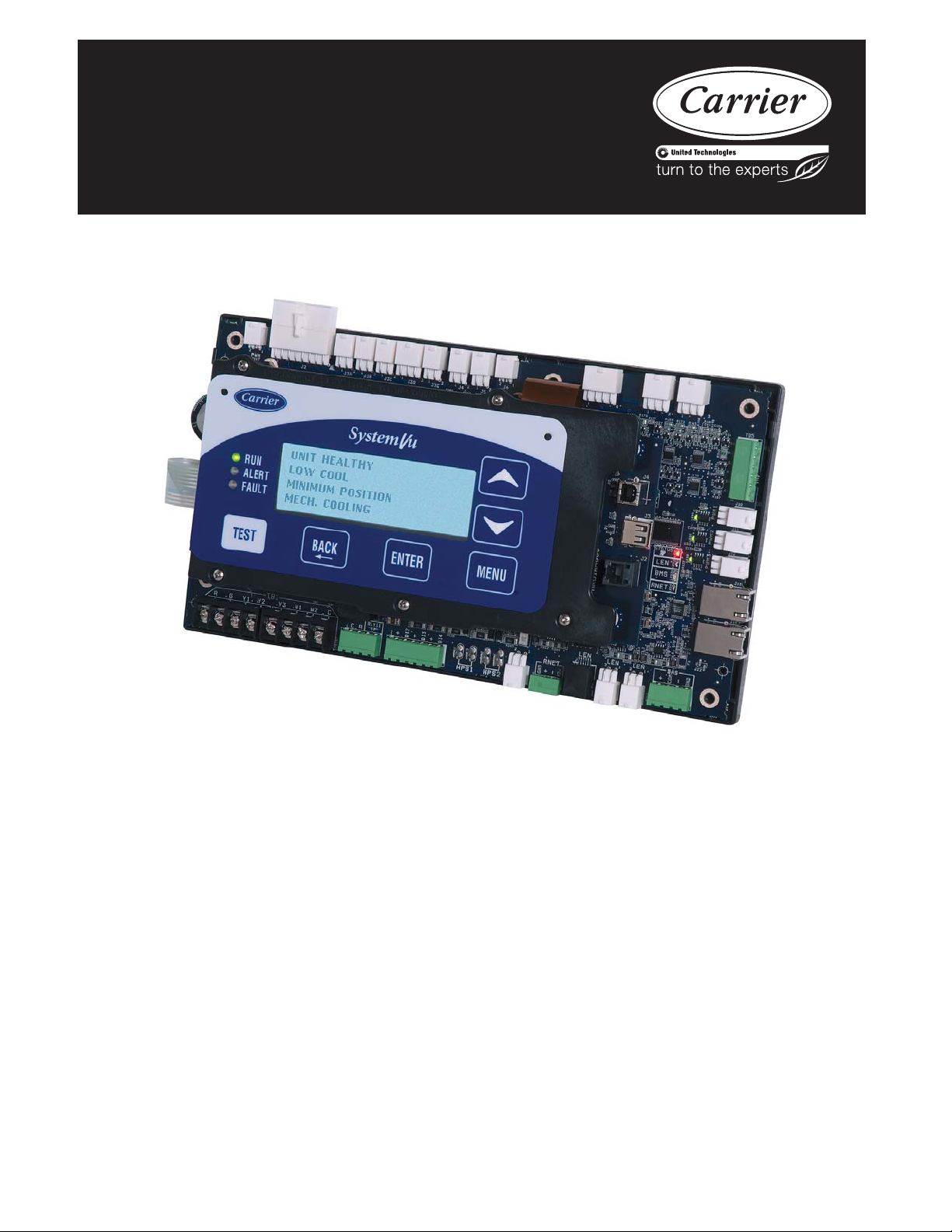
48/50LC 04--- 26
Single Package Rooftop Units
with SystemVu™ Controls Version 2.X
and Puronr (R---410A) Refrigerant
Controls, Start-- Up, Operation
and Troubleshooti ng
IMPORTANT: This literature covers 48/50LC 04--26 models with SystemVu controls version 2.X (factory--installed option).
TABLE OF CONTENTS
Page
SAFETY CONSIDERATIONS 2.........................
GENERAL 3.........................................
Conventions Used in This Manual 3......................
BASIC CONTROL USAGE 3...........................
SystemVu Control 3..................................
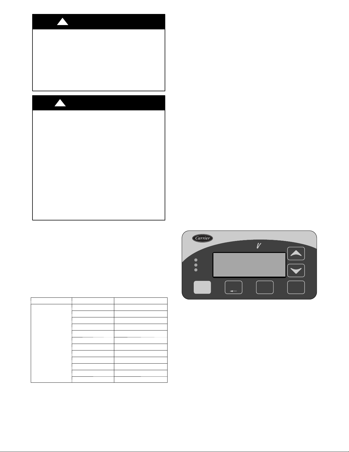
SystemVu Interface 3.................................
Accessory Navigatort Display 4........................
System Pilott andTouchPilott Devices 5................
CCN Tables and Display 5.............................
START--UP 6.........................................
Unit Preparation 6....................................
Refrigerant Service Ports 6.............................
Crankcase Heater 6...................................
Compressor Rotation 6................................
Power Supply 6.....................................
Internal Wiring 6.....................................
Evaporator Fan 6....................................
Condenser Fans and Motors 7...........................
Return--Air Filters 7..................................
Outdoor--Air Inlet Screens 7............................
Accessory Installation 7...............................
Gas Heat (48LC) 8...................................
CONTROLS QUICK SET--UP 9.........................
Control Set Point and Confirmation Log 9.................
Initial Startup 9......................................
Thermostat Control 9.................................
Space Temperature Sensor Control -- Direct Wired
(T--55 or T--56 or T--59) 9.............................
Space Humidistat Control 9............................
Relative Humidity Sensor Control 9......................
CCN Communication 10..............................
CCN Linkage Control 10..............................
System Pilott -- Communication Space Sensor 10..........
Accessories 10......................................
1
C150173
Page 2
Programming Operating Schedules 10....................
SERVICE TEST 11....................................
Independent Outputs 11...............................
Fan Test 11.........................................
Cooling Test 11.....................................
Heating Test 11......................................
Automatic Test 12....................................
THIRD PARTY CONTROL 12..........................
Cooling/Heating Control 12............................
Dehumidification Control 12...........................
Remote Occupancy 12................................
Remote Shutdown 12.................................
Alarm Output 12.....................................
Economizer Damper Control 12.........................
CONTROLS OPERATION 12...........................
Display Configuration 12..............................
Unit Configuration 13.................................
General Operation 13.................................
Demand Determination 14.............................
Occupancy Determination 15...........................
Indoor Fan Operation 16...............................
Cooling Operation 17.................................
Optional Humidi--MiZer
Indoor Fan Based Dehumidification 22...................
Heating Operation 22.................................
Supply Air Tempering 24..............................
Economizer Operation 24..............................
Power Exhaust 26....................................
Indoor Air Quality (IAQ) 26............................
Pre--occupancy Purge 27...............................
Temperature Compensated Start 27.......................
Linkage 28.........................................
Carrier Comfort Network
BACnet Network Operation 28.........................
Alarm Handling 28...................................
TROUBLESHOOTING 28..............................
Complete Unit Stoppage 29............................
Restart Procedure 29..................................
Faults and Alerts 29..................................
Control Module Communication 36......................
Communication Failures 36............................
Cooling Troubleshooting 37............................
Humidi--MiZer System Troubleshooting 38................
Economizer Troubleshooting 40.........................
Heating Troubleshooting 41............................
Phase Protection 44..................................
Thermistor Troubleshooting 44.........................
Sensor Trim 44......................................
Transducer Troubleshooting 44.........................
R
Dehumidification System 19......
R
(CCN) Operation 28............
MAJOR SYSTEM COMPONENTS 49....................
General 49.........................................
Main Base Board (MBB) 55............................
Input--Output Board (IOB) 57..........................
Integrated Gas Control (IGC) Board 58...................
Protective Devices 59.................................
Space Mounted Sensors 59.............................
Variable Frequency Drive (VFD) 61......................
LC 04 -- 06 Variable Frequency Drive (ABB VFD) 61.......
LC 07 --26 Variable Frequency Drive (Danfoss VFD) 65.....
Carrier Comfort Network
APPENDIX A: SystemVut Controller Display 76...........
APPENDIX B: SystemVu Controller Text Point Reference 97...
APPENDIX C: Navigatort Display 98....................
APPENDIX D: SystemVu Controller CCN Tables 117.........
APPENDIX E: BACnet Points List 142....................
CONTROL SET POINT AND CONFIGURATION L OG 153...
UNIT S TART--UP CHECKLIST 163......................
R
(CCN) Interface 74.............
SAFETY CONSIDERATIONS
Installation and servicing of air-conditioning equipment can be
hazardous due to system pressure and electrical components. Only
trained and qualified service personnel should install, repair, or
service air-conditioning equipment. Untrained personnel can
perform the basic maintenance functions of replacing filters.
Trained service personnel should perform all other operations.
When working on air-conditioning equipment, observe precautions in
the literature, tags and labels attached to the unit, and other safety
precautions that may apply. Follow all safety codes. Wear safety
glasses and work gloves. Use quenchi ng cloth for unbrazing
operations. Have fire exti ngui shers availa ble for all brazing operations.
Follow all safety codes. Wear safety glasses and work gloves. Have
fire extinguisher available. Read these instructions thoroughly and
follow all warnings or cautions attached to the unit. Consult local
building codes and National Electrical Code (NEC) for special
requirements.
Recognize safety information. This is the safety-- alert symbol
When you see this symbol on the unit and in instructions or
manuals, be alert to the potential for personal injury.
Understa nd the signal words DANGER, WARNING, and CAUTION.
These words are used with the safet y--aler t symbol. DANGER
identifies the most serious hazards which will result in severe personal
injury or death. WARNING signifies a hazard which could result in
personal injury or death. CAUTION is used to identify unsafe
practices which may result in minor personal injury or product a nd
property damage. NOTE is used to highlight suggesti ons which will
result in enhanced installation, reliability, or operation.
!
WARNING
ELECTRICAL SHOCK HAZARD
Failure to follow this warning could cause personal injury
or death.
Before performing service or maintenance operations on
unit, turn off main power switch to unit and install lockout
tag. Ensure electrical service to rooftop unit agrees with
voltage and amperage listed on the unit rating plate.
.
2
Page 3
!
CAUTION
UNIT DAMAGE HAZARD
Failure to follow this caution may cause equipment
damage.
This unit uses a microprocessor--based electronic control
system. Do not use jumpers or other tools to short out
components or to bypass or otherwise depart from
recommended procedures. Any short--to--ground of the
control board or accompanying wiring may destroy the
electronic modules or electrical components.
!
WARNING
FIRE, EXPLOSION HAZARD
Failure to follow this warning could result in personal
injury, death and/or property damage.
Improper installation, adjustment, alteration, service, or
maintenance can cause property damage, personal injury, or
loss of life. Refer to the User’s Information Manual
provided with this unit for more details.
Do not store or use gasoline or other flammable vapors and
liquids in the vicinity of this or any other appliance. What
to do if you smell gas:
1. DO NOT try to light any appliance.
2. DO NOT touch any electrical switch, or use any phone in
your building.
3. IMMEDIATELY call your gas supplier from a neighbor’s
phone. Follow the gas supplier’s instructions.
4. If you cannot reach your gas supplier, call the fire
department.
GENERAL
This publication contains Start--Up, Controls, Operation, Service,
and Troubleshooting information for the 48/50LC rooftop units
equipped with the factory--installed optional SystemVut controls
(version 2.X or higher) and use Puronr (R--410A) refrigerant. The
specific base unit installation instructions, service manual and/or
wiring label diagram may also be required in conjunction with this
book as a guide to a specific unit on the roof. All units in Table 1
are Staged Air Volume (SAVt) units that allow for stand--alone or
network operation.
Table 1 – Rooftop Units
MODEL SIZE NOMINAL TONS
04 3
05 4
06 5
07 6
08 7.5
48/50LC
Conventions Used in This Manual
The following conventions for discussing configuration points for
the local display (SystemVu controller or Navigatort accessory)
will be used in this manual.
Menu paths will be written with the main menu name first, then
any menus or sub menus, each separated by an arrow symbol ()
09 8.5
12 10
14 12.5
17 15
20 17.5
24 20
26 23
and will also be shown in bold and italics. As an example, the
General sub menu which is located in the Setting main menu under
Unit Configuration menu would be written as SETTINGS
UNIT CONFIGURATIONSGENERAL.
This path name will show the user how to navigate through the
local display to reach the desired menu. The user scrolls through
the Menus using the up and down keys. The arrow symbol in the
path name represents pressing ENTER to move into the next level
of the menu structure.
Point names are referenced in in parentheses and bold and italics as
would be shown on the local display.
CCN point names are also referenced for users configuring the
unit with C C N software instead of the lo cal display. S ee
Appendix A at the end of this manual.
BASIC CONTROL USAGE
SystemVu Control (factory--installed option)
The SystemVu control is a comprehensive unit-management
system. The control system is easy to access, configure, diagnose
and troubleshoot.
The SystemVu control system is fully communicating and
cable-ready for connection to the Carrier Comfort Network
(CCN), Carrier i--Vu, and Third Party BACnet* building
management systems. The control provides high-speed
communications for remote monitoring via the Internet. Multiple
units can be linked together (and to other Direct Digital Control
(DDC) equipped units) using a 3-wire communication bus.
The SystemVu control system is easy to access through the use of a
integrated display module. A computer is not required for start-up.
Access to control menus is simplified by the ability to quickly
select from 7 main menu items. An expanded readout provides
detailed explanations of control information. Only six buttons are
required to maneuver through the entire controls menu. The
display readout is designed to be visible even in bright sunlight.
System u
RUN
ALERT
FAULT
TESTTEST
SystemVu Interface
This integrated device is the keypad interface used to access the
control information, read sensor values, and test the unit. The
interface is located in the main control box and is standard on all
units. The interface is a 6 --key, 4x30 character, LCD (liquid--crystal
display) display module. The interface also contains Status LEDs.
(See Fig. 1.) The interface is easy to operate using 6 buttons and
themainmenustructuresshowninFig.2.
Through the SystemVu interface, the user can access all of the
inputs and outputs to check on their values and status, configure
operating parameters, and evaluate the current decision status for
operating modes. The control also includes an alarm history which
can be accessed from the display. The user can access a built--in test
routine that can be used at start--up commissioning and
troubleshooting.
* BACnet is a registered trademark of ASHRAE (American Society of
Heating, Refrigerating and Air ---Conditioning Engineers).
BACK ENTER MENU
C14319
Fig. 1 -- SystemVu Interface
3
Page 4
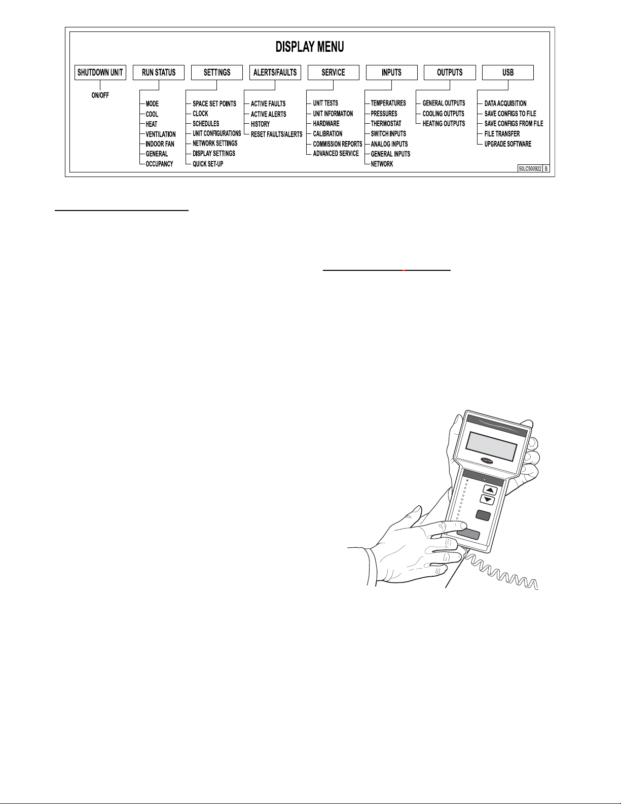
Fig. 2 -- SystemVut -- Main Menu Structures
SystemVu Interface Operation
Units are shipped from the factory with the SystemVu interface
FIOP, located in the main control box. (See Fig. 1.) In addition, the
interface has up and down arrow keys, BACK, ENTER, MENU,
and TEST keys. These keys are used to navigate through the
different levels of the menu structure. All discussions and examples
in this document will be based on the SystemVu display except in
the Navigatort display section. See the Accessory Navigator
Display section starting on page 4 for further details and Table 2
for the Navigator menu structure and usage.
The six keys are used to navigate through the display structure,
which is organized in a tiered menu structure. If the buttons have
not been used for a period, the display will default to a standby
screen intended to provide a quick overall look at the system. To
show the top-- level display, press any key first to turn the display
backlight on, and then press the MENU key. Then use the up and
down arrow keys to scroll through the top --level menus. These are
showninFig.2andlistedinAppendixA.
When a specific menu or sub--menu is located, push the ENTER
key to enter the menu. Depending on the menu, there may be
additional tiers. Continue to use the up and down keys and the
ENTER key until the desired display item is found. At any time,
the user can move back a menu level by pressing the BACK key.
Once an item has been selected the display will flash showing the
item, followed by the item value and then followed by the item
units (if any). Pressing the TEST button at any time will jump the
display to the test menu. Pressing the MENU button any time will
jump the display to the main menu.
Items in the Configuration and Service Test menus are password
protected. The display will prompt the enter password screen when
required. Use the ENTER, BACK, and arrow keys to enter the four
digits of the password. The default user password is 1111.
Pressing the BACK and ENTER keys simultaneously will show an
expanded text description screen on the display indicating the full
meaning of each display point. To put the screen in standby, hold
down the BACK key for 5 seconds.
Some points can be force d from the System Vut interface. To force a
variable, follow the same process as editing a configuration
parameter. A forced variable, regardless where the force has come
from will be displayed with a lower case “f” following its value.
For example, if ECON CMD POSITION is forced, the display
shows “80%f”, where the “f” is to signify a force on the point.
Remove the force by selecting the point that is forced with the key
ENTER and then pressing the up and down arrow keys
simultaneously. Pressing ENTER and BACK on a forced item will
display the expanded description for that item including the force
level that is currently applied. Depending on the type of unit
(48LC or 50LC), factory--installed options and field--installed
accessories, some of the items in the various menus may not apply.
a48--- 9373
Accessory Navigatort Display
The accessory hand-held Navigator display can be used with the
48/50LC units. (See Fig. 3.) The Navigator display is plugged into
the LEN (local equipment network) port on either the SystemVu
display or the Main Base Board (MBB).
Navigator Display Operation
The Navigator display has up and down arrow keys, an ESCAPE
key and an ENTER key. These keys are used to navigate through
the different levels of the display structure.
The four keys are used to navigate through the display structure,
which is organized in a tiered mode structure. If the buttons have
not been used for a period, the display will default to the AUTO
VIEW display category as shown under the RUN STATUS
category. To show the top-level display, press the ESCAPE key
until a blank display is shown. Then use the up and down arrow
keys to scroll through the top-level categories. These are listed in
Appendix C and will be indicated on the Navigator display by the
LED next to each mode listed on the face of the display.
C
o
m
f
o
r
t
L
N
in
A
V
I
k
G
A
T
O
T
IM
E
W
L
W
S
E
T
M
O
Ru
n Sta
S
e
rv
ice
T
em
p
era
P
res
s
ure
S
e
tpo
in
ts
In
pu
ts
O
utp
uts
C
on
fig
u
ra
tion
T
im
e C
lo
ck
O
p
er
ating
M
od
es
A
la
rm
s
E
N
T
E
R
Fig. 3 -- Accessory Navigator Display
When a spe cific mode or sub-mode is locate d, push the ENTER key
to e nt er the mode. De pending on t he mode, there may be additional
tier s. Continue to use the up and down ke ys and the ENTER keys
until the desire d display item is found. At any time, the user can move
back a mode level by pre ssing the ESCAPE key. Once an i tem has
been selected the display will flash showing the item, followed by the
item value and then followed by the item units (if any).
Items in the Configuration and Service Test modes are password
protected. The display will flash PASS and WORD when required.
Use the ENTER and arrow keys to enter the four digits of the
password. The default password is 1111.
R
E
1
2
T
.
5
8
5
4
T
.
6
°
F
4
4
P
.1
°
F
4
4
.
0
°
F
D
E
Ala
rm
Sta
tus
tu
s
Te
s
t
ture
s
s
E
S
C
C06321
4
Page 5
RUN
STAT US
Auto View of
Run Status
(VIEW)
Cooling
Status
(COOL)
Heating
Status
(HEAT)
Vent ilat ion
Status
(VENT)
Indoor Fan
Status
(I.FAN)
General
Status
(GEN)
Occupancy
Data
(OCC)
Run Hours
&Cycles
(RUN)
Assigned I/O
Channels
(A.IO)
Vers io ns
(VERS)
SERVICE
TEST
Service T est
Mode
(TEST)
T es t Independent
Outputs
(INDP)
Te s t F a n s
(FANS)
Test Cooling
(COOL)
Te s t H e a t i n g
(HEAT)
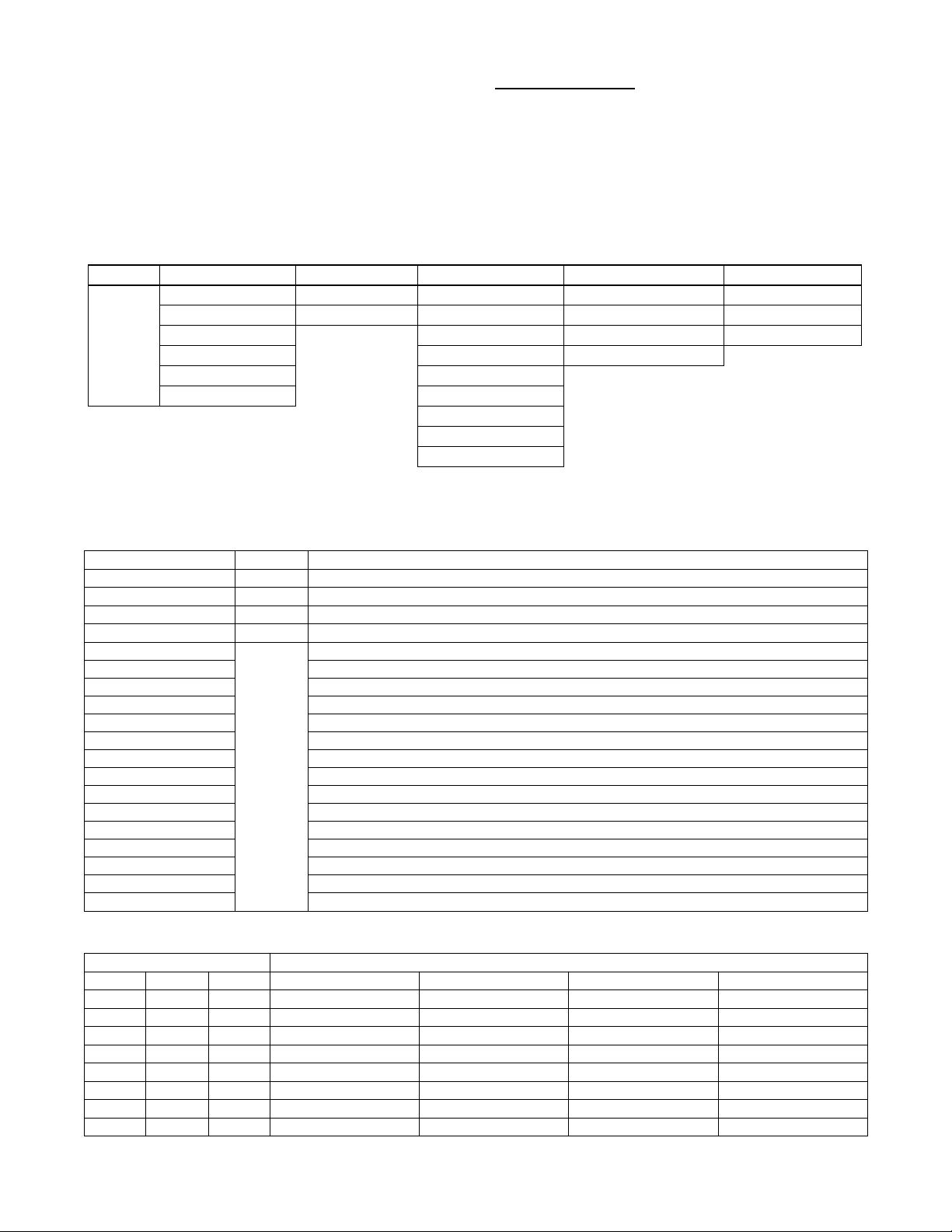
Table 2 – Navigator Mode and Menu Display Structure
TEMPERATURES PRESSURES
SET-
POINTS
Te m p
Demand
Config
(T .DMD)
Demand
Limit Config
(DMD.C)
INPUTS OUTPUTS CONFIGURATION TIMECLOCK
Thermostat
Inputs
(STAT)
Switch
Inputs
(SW)
Analog
Inputs
(AIS)
General
Inputs
(GEN)
Network
(NET)
Hardware
Inputs
(HW)
User
Measured
Data
(DATA)
General
Outputs
(GEN)
Cooling
Outputs
(COOL)
Heating
Outputs
(HEAT)
General Unit
Config
(GEN)
DI Config
(DIS)
Analog Input
Config
(AIS)
Cooling Configs
(COOL)
Outdoor Fans
Config
(ODF)
Heating Config
(HEAT)
Indoor Fan
Config
(I.FAN)
Economizer
Config
(ECON)
Air Quality
Config
(AIR.Q)
Alarm Relay
Config.
(ALM.O)
Calibration
(CAL)
Building Net
Config
(NET)
User Display
Config
(DISP)
Daylight
Savings
Config
(DST)
Schedules
Adjust
(SCHD)
Holiday
Adjustment
(HLDY)
OPERATING
MODES
Demand Limit
Status
(DMD.S)
ALARMS
Curr Active
Alarm
(CURR)
History
(HIST)
Reset All
Current
Alarms
(R.CUR )
Alarm Reset
History
(R.HIS)
Pressing the ESC and ENTER keys simultaneously will display an
expanded text description across the display indicating the full
meaning of each display point. Pressing the ESCAPE and ENTER
keys when the display is blank (MODE LED level) will return the
display to its default menu of rotating AUTO VIEW display items.
In addition, the password will need to be entered again before
changes can be made.
Changing item values or testing outputs is accomplished in the
same manner. Locate and display the desired item. If the display is
in rotating auto-view, press the ENTER key to stop the display at
the desired item. Press the ENTER key again so that the item value
flashes. Use the arrow keys to change the value of state of an item
and press the ENTER key to accept it. Press the ESCAPE key and
the item, value or units display will resume. Repeat the process as
required for other items.
There are some points that can be forced from the Navigator
display. If the user needs to force a variable, follow the same
process as when editing a configuration parameter. A forced
variable, regardless where the force has come from will be
displayed with a blinking “f” on a Navigator display following its
value. For example, if economizer commanded position (EC.CP) is
forced, the Navigatort display shows “80f”, where the “f” is
blinking to signify a force on the point. Remove the force by
selecting the point that is forced with the key ENTER and then
pressing the up and down arrow keys simultaneously.
Depending on the type of unit (48LC or 50LC), factory-installed
options and field-installed accessories, some of the items in the
various Mode categories may not apply.
See Table 2 and Appendix C for full Navigator display menu
layout.
System Pilott and Touch Pilott Devices
The System Pilot device (33PILOT-01) and T ouch Pilot device
(33CNTPILOT) can be used as CCN communication
user--interfaces. These devices can be put on the CCN bus and
addressed to communicate with any other device on the network.
Unlike the SystemVut display and Navigator display, these pilots
read the unit’s CCN tables and its CCN points can be monitored,
forced, or configured. The Pilot devices can be used to install and
commission a 3Vt zoning system, linkage compatible air source,
universal controller, and all other devices operating o n the Carrier
communicating network.
Additionally, the System Pilot device can serve as a wall-mounted
temperature sensor for space temperature measurement. Occupants
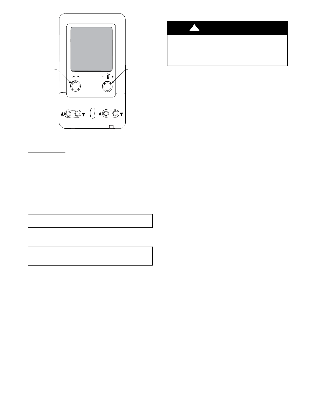
can use the System Pilot device to change set points. See Fig. 4 for
System Pilot device details.
CCN Tables and Display
In addition to the unit--mounted SystemVut display, the user can
also access the same information through the CCN tables by using
the service tool or other CCN programs/devices. The variable
names used for the CCN tables and the SystemVu display menus
may be different and more items may be displayed in the CCN
tables. Details on the CCN tables are included in Appendix D.
5
Page 6
NAVIGATE/
/
EXIT
SCROLL
Fig. 4 -- System Pilott User Interface
+
-
PAGE
MODIFY
SELECT
C06322
Force Hierarchy
There is a hierarchy in SystemVu controls with regards to forcing a
point. Programs and devices write a force at different priority
levels. A higher level (smaller number, 1 being the highest) will
override a lower level force. The SystemVu controller uses a
Control Force at level 7. The Navigatort device writes a Service
Force which is level 3. System Pilott and Touch Pilott devices
write Supervisor Forces at level 4. Network programs can be set to
write different level priority forces.
NOTE: In the case of a control power reset, any force in effect at
the time of power reset will be cleared.
IMPORTANT: All further discussions and examples in this
document will be based on the SystemVut controller.
START-UP
IMPORTANT: Do not attempt to start unit, even momentarily,
until all items on the Start--Up Checklist (see page 163) and the
following steps have been read/completed.
Unit Preparation
Check that unit has been installed in accordance with these
installation instructions and all applicable codes.
Refrigerant Service Ports
The refrigerant system has a total of 3 Schrader-type service gauge
ports per circuit. One port is located on the suction line, one on the
compressor discharge line, and one on the liquid line. Be sure that
caps on the ports are tight.
Crankca se Heater
The compressor is equipped with a crankcase heater. There is a control
function used to turn the crankcase heate rs on and off when the
compre ssor is not r unni ng. This is a configurable value for which t he
factory default value is set to 65_F . If the ambie nt is above the select ed
value the control will preve nt the crankca se heater from turning on.
IMPORTANT: Unit power must be on for 24 hours prior to
start--up to allow the crankcase heater to run. Otherwise, damage to
the compressor may result.
Compressor Rotation
!
CAUTION
UNIT DAMAGE HAZARD
Failure to follow this caution may result in unit damage.
Improper wiring will cause compressor stoppage and alarm.
Correct wiring by switching leads as indicated below.
On 3-phase units, it is impor tant to be cer tain the compressors are
rotating in the proper dire ction. To determine whether or not
compre ssors are rot ating in the prope r directi on, use a phase-rot ation
mete r on the uni t input power to che c k for L1-L2-L3 or cloc kwise
rotation or use the Service Te st mode to ener gize a c ompressor. If the
compre ssor is rotati ng in the wrong direction, the controls will stop the
compressor and display alarm for “Circ ui t A Reverse Rotati on”.
NOTE: Indoor or outdoor fan rotation direction may not indicate
proper input power phase sequence, as some 3-phase units use
single-phase fan motors.
To correct the wrong compressor rotation direction, perform the
following procedure:
1. Turn off power to the unit and lock out the power.
2. Switch any two of the incoming unit power leads.
3. Turn on power to the unit.
4. Verify corrected compressor rotation.
Power Supply
All 208/230-v units are factory wired for 230-v power supply. If
the 208/230-v unit is to be connected to a 208-v power supply, the
transformers must be rewired by moving the wire from the
230-volt connection and moving to the 200-volt terminal on the
primary side of the transformer. Refer to unit label diagram for
additional information.
Internal Wiring
Check all electrical connections in unit control boxes; tighten as
required.
Evaporator Fan
The evaporator fan should be checked and may need to be adjusted
for specific applications. The unit will have a belt drive motor
powered by a Variable Frequency Drive (VFD). Refer to the unit
product data for Fan Performance tables and physical data.
The fan belt and variable pulleys are fact ory installed and set, but may
need to be adjusted for specific applications. Check the fan to ensure
its rotation is in the proper direction before adjusting performance. T o
alter fan performance, first adj ust the pulley sett ings to provide the
application’s full load design air flow when running at the IDF
Maximum Fan Speed (MAXIMUM IDF SPEED). The unit
operating speeds can then be adjusted with Free Cooling IDF Speed
(FREE COOL IDF SPEED), High Cooling IDF Speed (HIGH
COOL IDF SPEED), Medium Cooling IDF Speed (MED COOL
IDF SPEED), Low Cooling IDF Speed (LOW COOL IDF
SPEED), Heating IDF Speed (HEATI NG IDF SPEED),and
V entilation Only IDF Speed (VENT IDF SPEED). Set the indoor fan
pulley to the greate r appli cation design point CFM for heating or
cooling and e qual t o 100% fan speed. Adjust the Heating Fan Spe ed
and High Cooling Fan Speed so that the CFM is not lower than the
minimum CFM allowed in the product data. If the exact CFM cannot
be set by the half turn pulley settings then adjust the IDF Maximum
Fan Speed (MAXIMUM IDF SPEED) to fine tune the CFM to the
application requirements. The VFD’s settings should not be used for
adjusting fan performance. Specif ic VFD i nformation can be found in
the major components secti on.
6
Page 7
IMPORTANT: The IDF Maximum Fan Speed (MAXIMUM
IDF SPEED) RPM must not produce a supply CFM that is
lower than the minimum CFM allowed in the product data for
heating and cooling.
Condenser Fans and Motors
Condenser fans and motors are factory set.
Return--Air Filters
Check that correct filters are installed in filter tracks (see Physical
Data table in unit Product Data). Do not operate unit without
return-air filters. Determine the filter change run time (DIRTY
FILTER TIME) to be set in the quick setup configurations menu.
Outdoor--Air Inlet Screens
Outdoor-air inlet screens must be in place before operating unit.
Accessory Installation
Check to make sure that all accessories including space thermostats
and sensors have been installed and wired as required by the
instructions and unit wiring diagrams.
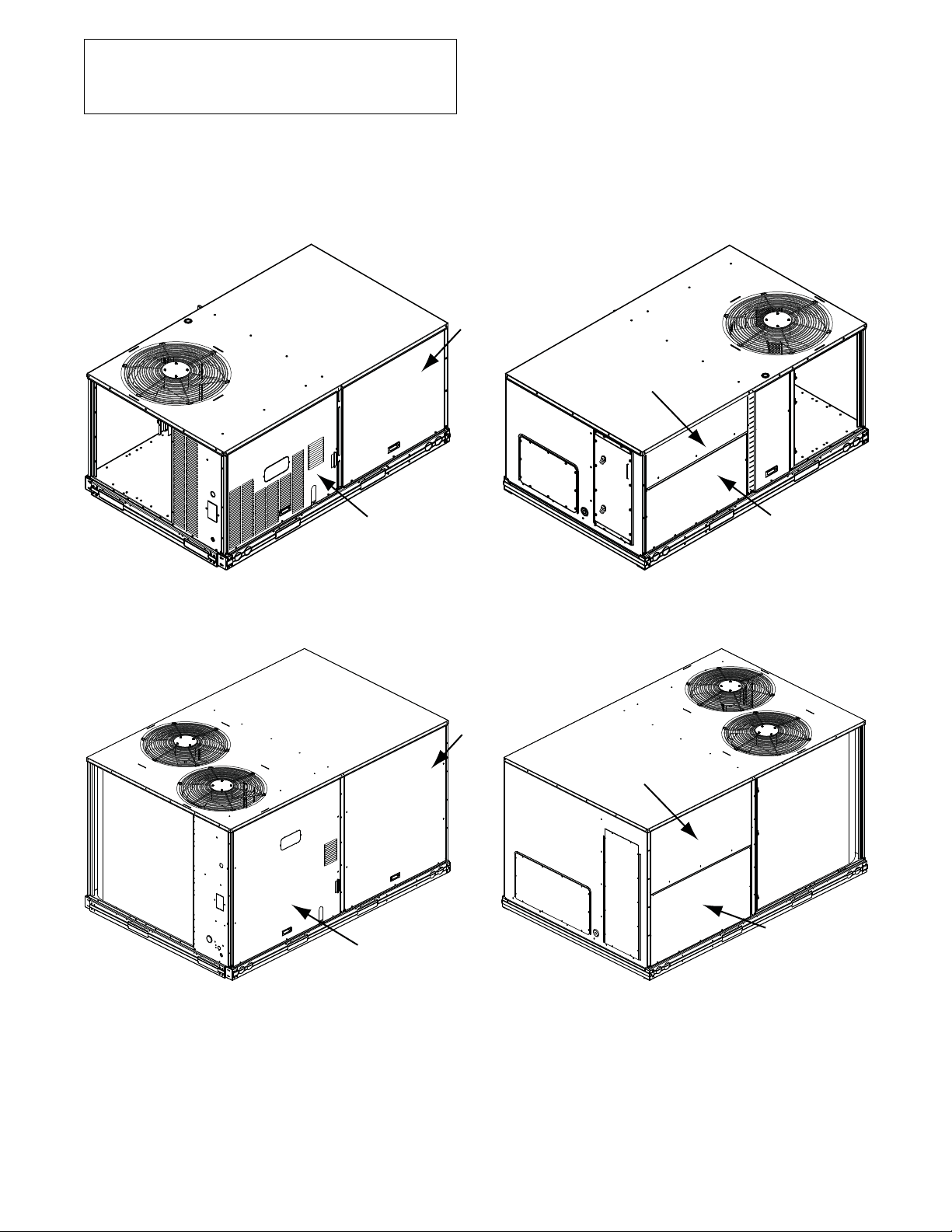
INDOOR
BLOWER
ACCESS
PAN EL
FILTER
ACCESS PANEL
CONTROL BOX
AND GAS SECTION
ACCESS PANEL
UNIT BACKUNIT FRONT
Fig. 5 -- 48/50LC Size 04--06 Units, Panel and Filter Locations (48LC*04 Unit Shown)
INDOOR
BLOWER
ACCESS
PAN EL
FILTER
ACCESS PANEL
CONTROL BOX
AND GAS SECTION
ACCESS PANEL
UNIT BACKUNIT FRONT
Fig. 6 -- 48/50LC Size 07 Units, Panel and Filter Locations (48LC*07 Unit Shown)
INDOOR COIL
ACCESS PANEL
a48--- 9937
INDOOR COIL
ACCESS PANEL
C14321
7
Page 8
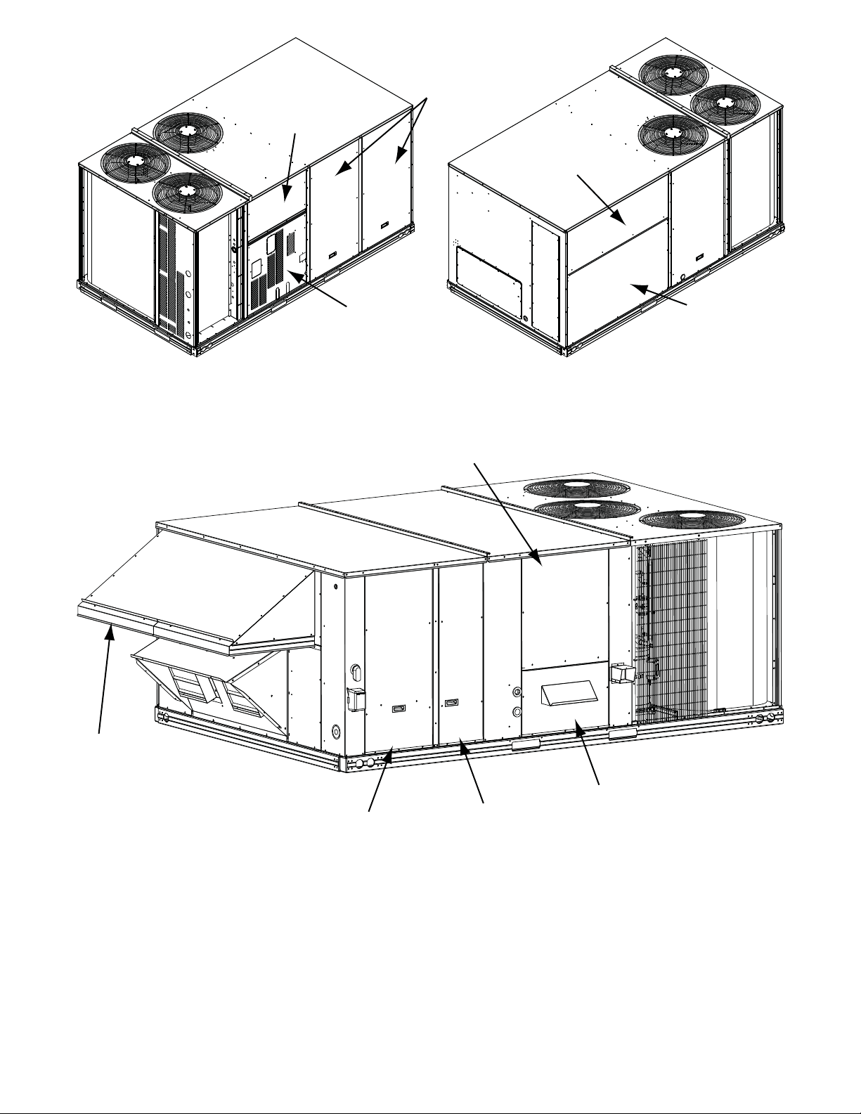
CONTROL BOX
ACCESS PANEL
INDOOR
BLOWER
ACCESS
PANELS
FILTER
ACCESS PANEL
GAS SECTION
ACCESS PANEL
UNIT BACKUNIT FRONT
Fig. 7 -- 48/50LC Size 08--12 Units, Panel and Filter Locations (48LC*09 Unit Shown)
INDOOR BLOWER
ACCESS PANEL
INDOOR COIL
ACCESS PANEL
C14322
OUTDOOR AIR
SCREEN
(HIDDEN)
CONTROL BOX
ACCESS PANEL
Fig. 8 -- 48/50LC Size 14--26 Units, Panel and Filter Locations (48LC*14 Unit Shown)
Gas Heat (48LC)
Inspect the gas heat section of the unit. Verify the number of
burners match the number of heat exchanger openings and the
burner assembly is properly aligned. If the orifices were changed
out for elevation or Liquid Propane purposes, verify proper
installation. Visually inspect other components in heat section.
GAS SECTION
FILTER AND
INDOOR COIL
ACCESS PANEL
ACCESS PANEL
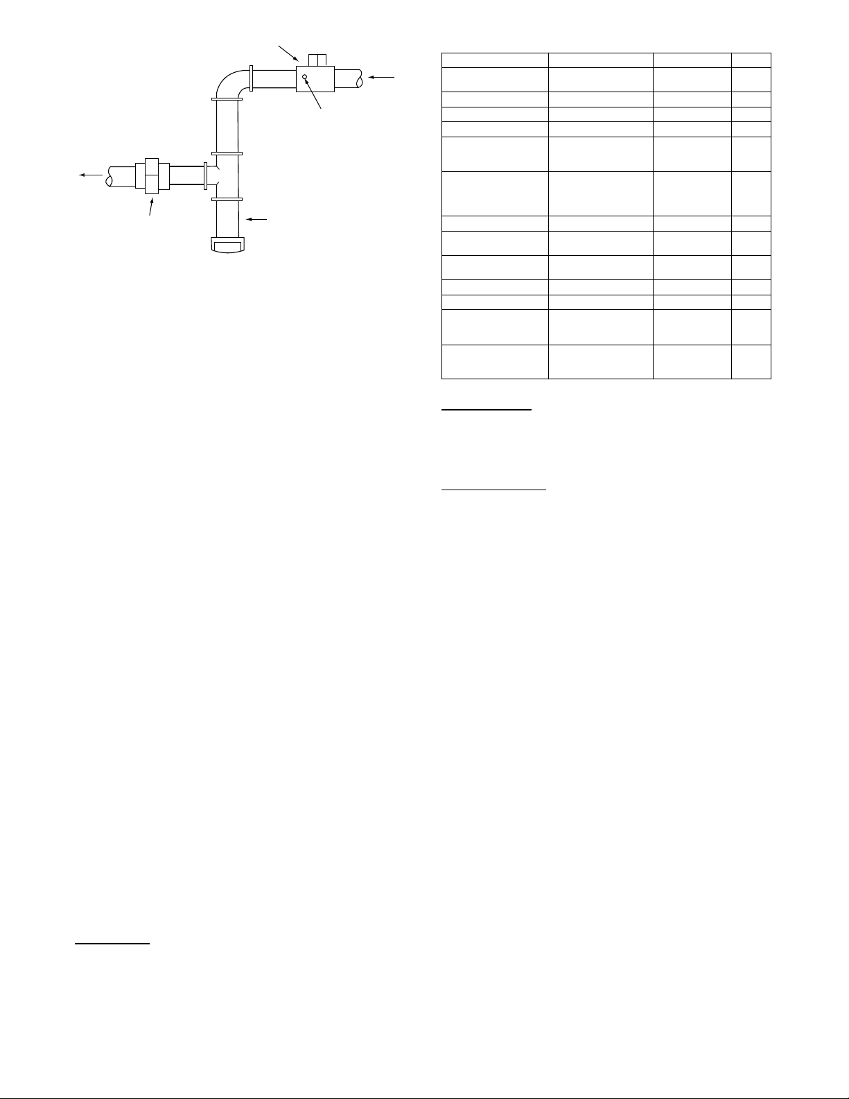
Verify gas pressures before turning on heat as follows:
1. Close the field-supplied manual gas shut off valve, located
external to the unit.
2. Connect a pressur e gauge to the supply gas pressur e tap,
located on the fie ld-supplied manual gas shut off val ve (see
Fig. 9).
8
C11475
Page 9
MANUAL GAS SHUT OFF VALVE
Y
(FIELD SUPPLIED)
GAS
SUPPL
SUPPLY GAS
PRESSURE TAP
(1/8˝ NPT PLUG)
TO
UNIT
UNION
SEDIMENT TRAP
a48--- 9382
Fig. 9 -- Field Gas Piping
3. Connect a pressure gauge to the manifold pressure tap on
the burner assembly located inside the unit.
4. Open the field- supplied manual gas shut off valve. Enter
Service Test mode by setting TEST MODE to “ON” using the
SystemVut controller interface. Use the Service Test feature
to set HEAT 1 TEST to ON (fi rst stage of heat ) using the
SystemVu controller interface.
5. After the unit has run for several minutes, verify the supply
gas pressure is adequate per the base unit installation instructions. If not, adjust accordingly.
NOTE: Supply gas pressure must not exceed 13.0--in. wg.
6. Set HEAT 1 TEST to OFF using the SystemVu controller
interface.
7. Exit Service Test mode by setting TEST MODE to “OFF”
using the SystemVu controller interface.
CONTROLS QUICK SET--UP
The following information will provide a quick guide to setting up
and configuring the 48/50LC seri es units with SystemVu control s.
Unit controls are pre- configured at the factory for factory-i nstalled
options. Field-installed accessories will require configuration at
start-up. Initial System Startup is recommended for initial start--up.
Additionally , specifi c job r equireme nt s may require changes to defaul t
configuration values. See Appendix A and other sect ions of these
instr uctions for more de tails. Refe r to the Major Sys t em Compone nts
or accessory installation instructions for specific wiring detail.
Control Set Point and Configuration Log
During start up, accessory installation, and equipment service set
points and/or configuration changes might have to be made. When
setting set points or configuration settings, documentation is
recommend. The Control Set Point and Configuration Log starting
on page 153 should be filled out and left with the unit at all times,
a copy should also be provided to the equipment owner. A USB
jump drive can be used to back up the unit’s configurations. Refer
to the USB Operation section for details.
Initial Startup
Initial Startup refers to the first time this particular unit has a startup
performed. The SystemVu controller will continually display the
Initial Startup prompt until it is completed. To complete the initial
startup you must complete the Quick Setup, Network Setup, and
the System Auto Test.
Quick Setup
This a list of common adjusted configurations set during startup.
These are common accessories, and control means. Set the list in
Table 3. After setting these per the specific unit set the QUICK
SET CHKLIST point to done.
Table 3 – Quick Setup Menu Items
SystemVu™ Display Expanded Name Range Default
QUICK SETUP CONFIG QUICK SETUP
TIME Clock Hour and Minute HH:MM
DATE Current Date MM/DD/YYYY
STARTUP DELAY Unit S tartup Delay 10 to 600 30
UNIT CONTR OL TYPE Unit Control Type 0=TSTAT,
THERMOSTAT TYPE Thermostat Hardware
DIRTY FILTER TIME Change Filter Timer 0to9999 600
VENT IDF SPEED Venti lation Only IDF
HEATINGSTAGQTY Number of Heating
ECON INSTALLED? Economizer Instal l ed? No/Yes No*
FREECOOL MAX OAT Free Cooling Max OAT 0to90 65
FIRE SHUTDOWN SW Fire Shutdown Switc h 0=No Switch,
QUICK SET CHKLIST QUICK SETUP
* These defaults change based on the Unit model number.
CONFIG MENU
Type
Speed
Stages
CHECKLIST
1=SPACE SEN,
2=RAT SEN
0=CONV 2C2H,
1=DIGI 2C2H,
2=CONV 3C2H,
3=DIGI 3C2H
0to100 67*
1to2 2*
1=N/Open
2=N/Close
0=Undone,
1=View,
2=Done
0
2
0*
0
Network Setup
This is a shortcut to the Network Settings submenu. In this sub
menu are the specific network settings required to get the network
piece up and running. After setting these per the specific unit set
the NETWORK CHKLIST point to done.
System Auto Test
Turning this to Start will run enable test mode and execute the System
Auto Test. After the auto test has completed, set this to done.
Thermostat Control
Wire accessory thermostat to the corresponding R, Y1, Y2, Y3,
W1, W2, and G terminals on the Main Base board.
The Unit Control Type configuration, (UNIT CONTROL TYPE)
default value is for thermostat (0) so there is no need to configure
this item.
The Thermostat Hardware Type, (THERMOSTAT TYPE) selects
the unit response to the thermostat inputs above.
NOTE: May not be compatible with heat anticipator thermostats.
Space Temperature Sensor Control -- Direct Wired
(T--55 or T--56 or T--59)
Wire accessory space temperature sensor(s) to the T-55 terminals
on the field connection terminal board located at the unit control
box. Refer to Space Mounted Sensors section (page 59) for
additional information.
The Unit Control Type configuration, (UNIT CONTROL TYPE)
must be set to Space Sensor (1).
Space Humidistat Control
For units with the factory--installed Humidi--MiZerRsystem
option, the humidistat input is provided with quick connects. The
Space Humidity Switch configuration, SETTINGS UNIT
CONFIGURATIONS SWITCH INPUTS CONFIGS
HUMSTAT CHANNEL identifies the normally open or normally
closed status of this input at HIGH humidity.
Relative Humidity Sensor Control
For units with the factory--installed Humidi--MiZer system option,
the humidity sensor input is provided with quick connects. The
sensor can be used instead of a humidistat. The RH Sensor
configuration, SETTINGS UNIT CONFIGURATIONS
ANALOG INPUTS CONFIGS SPRH SENSOR CHANNEL,
identifies the point on the MBB (Main Base board) or the IOB
(Input Output board) the sensor was wired into.
9
Page 10

CCN Communication
First configure the building protocol SETTINGS NETWORK
SETTINGS BAS PROTOCOL to CCN (default is 0 = NONE).
Configure the following under the CCN menu (SETTINGS
NETWORK SETTINGS CCN).
CCN ELEMENT # -- D e f a u l t i s 1
BUS NUMBER -- D e f a u l t i s 0
CCN BAUDRATE -- Default is 2 = 38400
CCN Linkage Control
The CCN communication must be properly configured for the
48/50LC units and all other devices. Linkage configuration is
automatically done by the supervisory CCN Linkage device.
The unit control type configuration, (UNIT CONTROL TYPE)
must be set to space sensor (1).
Installation of an accessory supply air temperature (SAT) sensor in
the supply duct is recommended for Linkage applications. A SAT
measurement is valid for heating mode display, while the
factory-standard internal SAT is not valid for heating due to its
location upstream of the heating section. When installing the
supply duct SAT, the heating mode display is enabled by setting
the SAT heat mode sensing configuration (SAT DURING HEAT?)
to Enable.
System Pilott -- Communication Space Sensor
Install the System Pilot device and connect the CCN communication
bus from it to the unit’s CCN connect i on on TB4 -- BAS connector of
the Main Base Board (MBB). Configure the unit’s CCN
communic ation element number, bus number, and ba ud rate. Refer to
the System Pilot’s installation instructions for configuring it to be used
as a space temperature and attaching it to a unit.
Accessories
Below are quick configuration settings for field--installed
accessories. When factory--installed as options the points will
already be configured. See the Space Mounted Sensors section
(page 59), third party control, control connection tables, and CCN
or Display parameter tables for any accessories not mentioned
below and refer to installation manual of the accessory.
Economizer
When an economizer is field--installed, the unit must be configured
for it by setting SETTINGSUNIT CONFIGURATIONS
ECONOMIZER ECON INSTALLED? to YES. The default
settings for the other economizer configurations should be
satisfactory. If they need to be changed, additional information
about these configuration settings can be found in the Economizer
section.
Power Exhaust
When power exhaust is field--installed, the unit must be
configu red for it by setting SETTINGSUNIT
CONFIGURATIONSECONOMIZER POWER EXHAUST
CONFIGS PE1 RELAY CHANNEL to the channel the
accessory was wired into. The default settings for the other power
exhaust configurations should be satisfactory. If they need to be
changed, additional information about these configurations can be
found in the Power Exhaust section.
Electric Heat
When electric heat is field--installed, the number of electric heat stages
must be configured by setting SETTINGS UNIT
CONFIGURATI ONS HEATING HEATING STAGE QTY
per the installed heater.
Fire Shutdown
When Fire Shutdown or Smoke Detector sensors are
field--installed, the unit must be configured for it by setting
SETTINGS UNIT CONFIGURATIONS SWITCH INPUTS
CONFIGS FIRE SHUTDOWN SW to normally open (0) or
normally closed (1).
Outdoor Enthalpy
When an Outdoor Enthalpy sensor is field-- installed, the unit must
be configured for it by setting SETTINGS UNIT
CONFIGURATI ONS ANALOG INPUTS CONFI GS OARH
SENSOR CHAN to the channel number the sensor was wired into.
IAQ Sensor
When a CO2sensor is field--installed, the unit must be
configu red fo r it by setting SETTINGS UNIT
CONFIGURATIONS ANALOG INPUT CONFIGS IAQ
SENSOR CHAN selects the unit response to this input. Default
conversion to 0 to 2000 ppm.
OAQ Sensor
When an Outdoor Air Quality sensor is field--installed, the unit
must be configured for it by setting SETTINGS UNIT
CONFIGURATIONS ANALOG INPUT CONFIGS OAQ
SENSOR CHAN. Default conversion to 0 to 2000 ppm.
Filter Status
When a Filter Status sensor is field--installed, the unit must be
configured for it by setting SETTINGSUNIT
CONFIGURATIONSSWITCH INPUT CONFIGS FILTER
SW CHANNEL to normally open (0) or normally closed (1).
Programming Operating Schedules
When the building automation system you have the SystemVut
controller configured for (BAS Protocol Select) is None (0) or
CCN (1) the SystemVu controller can follow a standard CCN
occupancy table. The occupancy can be modified from any CCN
tool or from the local display.
OCCUPANCY SCHEDULE — For flexibility of scheduling, the
occupancy programming is broken into eight separate periods. For
each period the schedule contains the following fields: Day of
Week, Occupied From, and Occupied To.
DAY OF WEEK — The day of week configuration consists of
eight fields corresponding to the seven days of the week and a
holiday field in the following order: Monday, Tuesday,
Wednesday, Thursday, Friday, Saturday, Sunday, and Holiday. If a
1 is configured in the corresponding place for a certain day of the
week, the related “Occupied from” and “Occupied to” times for
that period will take ef fect on that day of the week. If a 1 is placed
in the holiday field, the related times will take effect on a day
configured as a holiday. A zero means the schedule period will not
apply to that day.
Day of week: Range 0 or 1
Default Values 0 for all of the periods.
OCCUPIED FROM — This field is used to configure the hour and
minute, in 24 hour clock, that the mode for the controller will
switchtooccupied.
Occupied From: Units Hours:Minutes
Range 00:00 to 24:00
(Minutes 00 to 59)
Default Value 00:00
OCCUPIED TO — This field is used to configure the hour and
minute, in 24 hour clock, that the mode for the controller switches
from occupied to unoccupied.
Occupied To: Units Hours:Minutes
Range 00:00 to 24:00
(Minutes 00 to 59)
Default Value 00:00
When the building automation system configured to (BAS
PROTOCOL) is BACnet, the occupancy and holiday information
will be reset to defaults in preparation for receiving a BACnet
occupancy object. While participating on a BACnet network these
configurations cannot be changed at the local interface or with
CCN tools. All scheduling is done from the BACnet interface
designated to provide schedules.
10
Page 11
SERVICE TEST
The Ser vi ce Test f unction can be used to verify proper operation of
compre ssors, heating sta ges, indoor f an, outdoor fa ns ,
Humidi--MiZer
crankcase heaters, and the alarm relay. Use of Service Test is
recommended at initial system start up and during troubleshooting.
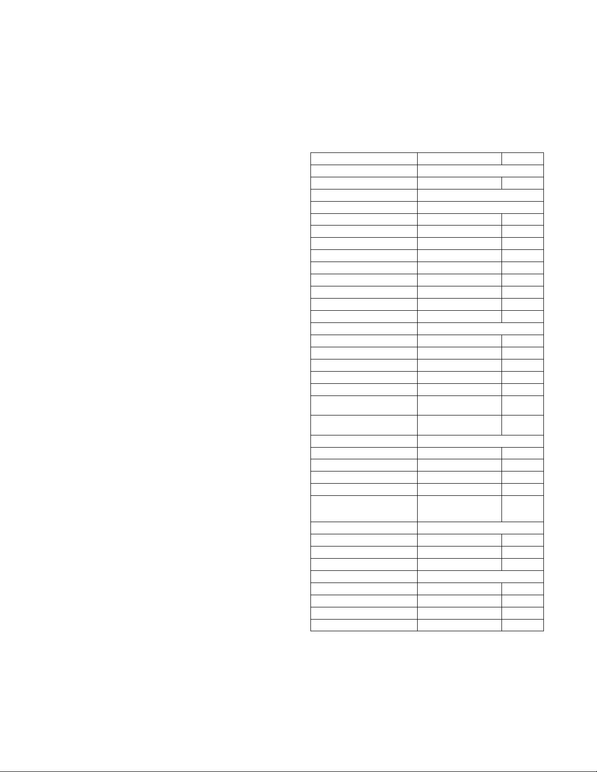
(See Table 4 for point deta i ls)
Service T est mode has the following changes from normal opera t ion:
S Outdoor air temperature limits for cooling circuits, economizer,
and heating are ignored.
S Normal compressor time guards and other staging delays are
reduced to one minute or less.
S Circuit strike out time is reduced to 1 minute instead of 15 minutes .
S It may take up to 30 seconds to actually enter test mode after
activating the command.
Press the TEST button on the SystemVut interface anytime to
access the Test menu. Service Test mode can only be turned
ON/OFF at the unit display. Once turned ON, other entries may be
made with the display or through CCN. To turn Service Test mode
on, change the value of TEST MODE to ON. To turn service test
mode off, change the value of TEST MODE to OFF. Service Test
mode will be automatically turned off based on keypad inactivity
and the Service Mode Test Time out (TEST MODE TIMEOUT).
NOTE: Service Test mode may be password protected. Refer to
Basic Control Usage section for more information. Depending on
the unit model, factory--installed options, and field--installed
accessories, some of the Service Test functions may not apply.
Independent Outputs
The INDEPENDENTS submenu is used to change output status for
the economize r, Humidi--MiZer system valves, power exhaust stages,
crankcase heaters, the alarm relay, as well as perform a compressor
bump test. These independent outputs can operate simultaneously with
other Servic e T est modes. All outputs return to normal operation when
Service Test is tur ned off . The compr essor bump tests c annot be run
while running cooling tests a nd will automa ticall y turn off after one
minute.
Fan Test
The FAN TE S T S submenu is used to change speed for the indoor
fan and outdoor fans. The outdoor fan speeds can be controlled
individual or all together with the ALL ODF SPD TEST.The
outdoor fan and indoor fan transition type points inform the test
routine how to handle the fans while running the cooling or
heating tests. Automatic will automatically transition the fans as the
cooling or heating tests change. While the Manual transition will
only run the fans as set by the test points.
Cooling Test
The COOL submenu is used to change output status for the
individual compressors and Humidi--MiZer system operation. The
HEAT submenu service test outputs are reset to OFF for the
cooling service test. Indoor fans and outdoor fans are controlled
normally to maintain proper unit operation when set for automatic
transition. The IDF SPEED TEST and ALL ODFSPD TEST can
be changed as needed for testing. These fans points show the
requested speed not actual speed. All normal cooling faults and
alerts are functional.
R
system operat ion, power exha ust fans, economizer,
Heating Test
The HEAT submenu is used to change output status for the
individual heat stages, gas or electric. The COOL service test
outputs are reset to OFF for the heating service test. Indoor fan is
controlled normally to maintain proper unit operation when set for
automatic transition. The IDF SPEED TEST can be changed as
needed for testing and shows the requested speed not actual speed.
All normal heating faults and alerts are functional.
NOTE: When the IGC fan on command (IGC FAN REQUEST)
is active the fan may run when not expected.
Table 4 – Test Mode Unit Test Directory
Display Menu/ Sub Menu / Name Expanded Name Values
UNIT TESTS Unit Tests Menu
TEST MODE ServiceTestModeEnable Off/On
SERVICE TEST Service Test Menu
INDEPENDENT S INDEPENDENT TEST MENU
ECON POS TEST Economizer Position Test 0 to 100
BUMP COMP A1 TEST Compressor Bump A1 Test Off/On
BUMP COMP A2 TEST Compressor Bump A2 Test Off/On
LIQ DIVERT A TEST Liquid Divert A Test Off/On
REHEAT A TEST Reheat A Test Off/On
CCH RELAY 1 TEST Crankcas e Heater 1 test Off/On
ALARM RELAY TEST Alarm Output Relay T e s t Off/On
PE1 RELAY TEST Power Ex haust 1 Test Off/On
PE2 RELAY TEST Power Ex haust 2 Test Off/On
FAN TEST S Indoor and Outdoor Fan tests
IDF SPEED TEST Indoor Fan Speed Test 0 to 100
ALL ODF SPD TEST System ODF speed test 0 to 2000
ODF 1 SPEED TEST Outdoor Fan 1 speed test 0 to 2000
ODF 2 SPEED TEST Outdoor Fan 2 speed test 0 to 2000
ODF 3 SPEED TEST Outdoor Fan 3 speed test 0 to 2000
IDF TRANSITION IDF Test T ransition Type Automatic /
ODF TRANSITION ODF T est T ransition Type Automatic/
COOL Coolin g Status Menu
COOL A1 TEST Cooling W/Comp.A1 Test Off/On
COOL A2 TEST Cooling W/Comp.A2 Test Off/On
IDF SPEED TEST Indoor Fan Speed Test 0 to 100
ALL ODF SPD TEST System ODF speed test 0 to 2000
HUMIDIMIZER TEST H umi d i --- M i Z e rRsystem test 0=off
HEAT Heating Status Menu
HEAT 1 TEST Heating Stage 1 Test Off/On
HEAT 2 TEST Heating Stage 2 Test Off/On
IDF SPEED TEST Indoor Fan Speed Test 0 to 100
AUTOMATIC TEST Autom atic Tes t Menu
AUTO INDP TEST AUTO INDEPENDENT TEST Ye s /N o
AUTO COOL TEST RUN AUTO COOLING TEST Yes /No
AUTO HEAT TEST RUN AUTO HEATING TEST Yes/ No
AUTO SYSTEM TEST RUN AUTO SYSTEM TEST Yes/ No
Manual
Manual
1 = Subcool
2=Reheat
11
Page 12
Automatic Test
The AUTOMATIC TEST submenu i s u sed to execu te all the
applicable tests to the system auto m atically. These in clude
independent component, cooling, heating, and a system one.
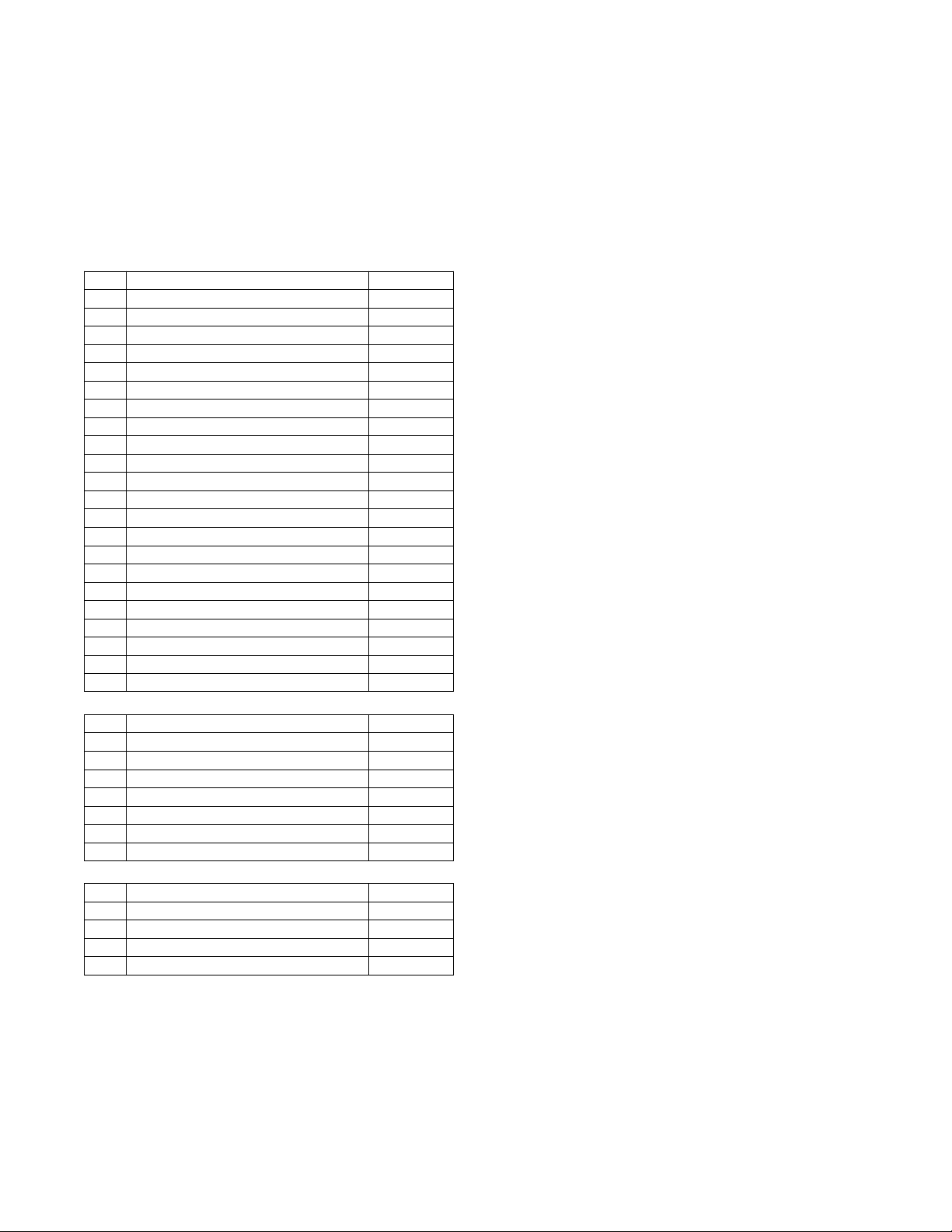
Table 5 shows the steps taken during the independent, cooling,
and heating autom atic tests. Th e Hold time represents the time at
which that control waits before moving on to the next step.
The AUTO SYSTEM TEST will execute the independent auto
test, then the cooling auto test, then the heating auto test. At the end
of the system auto test a prompt will ask if you want to enter
measured data and complete a service report.
Table 5 – Independent, Cooling, and Heating Automatic Tests
AUTO INDP TEST
Step Action Hold (Sec)
1 Turn on Crankcase Heater Relay 0
2 Set ODF1 to the High Cool Speed 30
3 Set ODF1 to the Minimum Speed 30
4 Tu r n O D F 1 o f f 5
5 Set ODF2 to the High Cool Speed 30
6 Set ODF2 to the Minimum Speed 30
7 Tu r n O D 2 1 o f f 5
8 Set ODF3 to the High Cool Speed 30
9 Set ODF3 to the Minimum Speed 30
10 Tu r n O D F 3 o ff 5
11 Set IDF speed to 100% 30
12 Set Economizer Damper to 100% 60
13 Tu r n o n pow e r e x h a u st 1 10
14 Tu r n o n pow e r e x h a u st 2 10
15 SetEconomizerDamperto0% 60
16 Turn off power exhaust 2 10
17 Turn off power exhaust 1 10
18 Set IDF to the ventilation speed 30
19 Turn on alarm relay 10
20 Turn off alarm relay 10
21 Set IDF to 0% speed 30
22 Turn off Crankcase Heater relay 0
AUTO COOL TEST
Step Action Hold (Sec)
1 Set ODF auto transition 0
2 Set IDF auto transition 0
3 Turn on Cool A1 test 60
4 Turn off Cool A1 test 30
5 Turn on Cool A2 test 60
6 Turn on Cool A1 and Cool A2 tests 30
7 Turn off Cool A1 and Cool A2 tests 60
AUTO HEAT TEST
Step Action Hold (Sec)
1 Set IDF auto transition 0
2 Turn on H e a t 1 t e st 60
3 Turn on H e a t 2 t e st 60
4 TurnoffHeat1andHeat2tests 20
THIRD PARTY CONTROL
Third party controls may interface with the unit SystemVut
controller through the connections described below. See other
sections of these instructions for more information on the related
unit control and configurations.
Cooling/Heating Control
The thermostat inputs are provided on TB1 of the board. The
Unit Control Type configuration, UNIT CONTROL TYPE,
must be 0 (Tstat) to recognize the below inputs. Terminal R is
the 24--VAC source for the following:
Y1 = first stage cooling
Y2 = second stage cooling
Y3 = third stage cooling
W1 = first stage heating
W2 = second stage heating
G = Indoor fan
Dehumidification Control
On Humidi--MiZerRsystem units the HUMIDISTAT and SPRH leads
are provided with quick connects . The Space Humidity Switch
configuration, SETTINGSUNIT CONFIGURATIONS
SWITCH INPUTS CONFIGSHUMSTA T CHANNEL
identifies the normally open or normally closed status of t his i nput at
HIGH humidity. The RH Sensor configurati on, SETTINGS UNI T
CONFIGURATI ONSANALOG INPUTS CONFIGS SPRH
SENSOR CHANNEL, identifie s the poi nt on the MBB (Main Base
board) or the IOB (Input Output board) the sensor was wired into.
Remote Occupancy
The remote occupancy input can be provided on one of the
configurable inputs, most commonly TB3. The Remote
Occupancy Switch configuration, REMOTE OCC TYPE,
identifies the normally open or normally closed status of this input
when unoccupied. The Remote Occupancy Channel configuration,
REMOTE OCC CHAN, identifies the discrete input (DI) assigned
for this function.
Remote Shutdown
The remote shutdown input is provided for unit shutdown in response
to switch input confi gured most commonly on TB3. The Remote
Shutdown Switch configurati on, REM. SHUTDOWN TYPE,
identifies the normally open or normally closed status of this input
when there is no shutdown command. The Remote Shutdown
Channel configura tion, REM. SHUTDOWN CHAN, identifies the
discrete input (DI) assi gned for this function.
Alarm Output
The alarm output is provided on as a configurable relay, most
commonly on TB2, to indicate when a current alarm is active. The
output will be 24 --VAC if a current alarm exists. The Alarm Relay
Channel configuration, ALM RELY CHANNEL, identifies the
discrete output (DO) assigned for this function.
Economizer Damper Control
For units with the economizer option or accessory, the damper
position can be directly controlled through the IAQ sensor input.
The IAQ Analog Input configuration, IAQ LEVEL CONTROL
will have to set to 2 (CTL MINP). When IA.CF = 2, an external 4
to 20 mA source is used to move the damper 0% to 100% directly.
CONTROLS OPERATION
Display Configuration
The SETTINGSDISPLAY SETTINGS submenu is used to
configure the local display settings.
METRIC DISPLAY
This variable is used to change the display from English units to
Metric units.
LANGUAGE
This variable is used to change the language of the SystemVu
display. At this time, only English is available.
CONTRAST ADJUST
This is used to adjust the contrast of the SystemVu display.
12
Page 13
PASSWORD ENABLE?
This variabl e enabl es or disable s the use of a user passw ord. The
passw ord is used to rest r ict use of the control to change configurations.
VIEW USER PASSWORD
This menu allows the user to view the user password. The
password must be entered or disabled to view it.
CHANGE USER PASSWORD
This menu allows the user to change the user password. The
password must be entered or disabled to change it.
Unit Configuration
Many configurations that indicate what factory options and/or field
accessories are installed and other common operation variables are
included in SETTINGSUNIT CONFIGURATION submenu.
Some of these configurations will be set in the factory for the
factory-- installed options (FIOPs). Field installed accessories and
custom control functions will require configuration changes. The
SETTINGSUNIT CONFIGURATIONGENERAL submenu
contains the following control configurations. Refer to other
specific sections for other configurations.
STARTUP DELAY
This configuration sets the control start-up delay after the power is
interrupted. This can be used to stagger the start-up of multiple
units.
UNIT CONTROL TYPE
This configuration defines if temperature control is based on
thermostat inputs or space temperature sensor input. TSTAT value
is when then unit determines cooling and heating demand by the
state of G, Y1, Y2, W1, and W2 inputs from a space thermostat.
This value is the factory default. SPACE SEN value is when the
unit determines cooling and heating demand based on the space
temperature and the appropriate set point. RAT SEN value is when
the unit determines cooling and heating demand based on the
return air temperature and the appropriate set point. SPACE SEN
or RAT SEN are also used as Linkage configuration.
THERMOSTAT TYPE
This configuration applies only if Unit Control Type is Thermostat.
The value determines how the inputs are interpreted. See the
specific operation sections for more information. The following
descriptions define what each value means.
0 = CONV 2C2H – Conventional Thermostat 2 stage cool and
2 stage heat.
1 = DIGI 2C2H – Digita l Thermos t at 2 stage cool and 2 stage heat.
2 = CONV 3C2H – Conventional Thermostat 3 stage cool and
2 stage heat. This is the default setting.
3 = DIGI 3C2H – Digital Thermostat 3 stage cool and 2 stage heat.
ADAPTIVE TSTAT
This configuration applies only if the Unit control type is
Thermostat. When this is YES the control will use Adaptive
Control for cooling and heating staging. When this is set to NO the
control will use the Traditional Thermostat Control, however
during integrated cooling Adaptive is always used.
DIRTY FILTER TIME
This configuration defines the life of the installed filter. A timer
will count down from this number while the indoor fan is running.
At the expiration of this timer, an alert will be activated to indicate
a filter change is required.
TEST MODE TIMEOUT
This configuration defines the time at which a test mode test has
not changed state will automatically disable test mode. This
configuration will disable the timeout when set to 0 (Disabled).
CCH MAX TEMP
This configuration defines the temperature threshold for which the
crankcase heater is no longer required to heat the compressor shell.
STD BARO PRESSURE
This configuration is used to specify the job locati on’s standard
barometer pressure reading. This will feed the BAROMETRIC
PRESS when a network is not writing to it. This should be used to
account for job site eleva t ion if enthalpy calcula t ions are being used.
LINK STAGEUP TIME
This configuration sets the cooling and heating stage up time
during linkage operation.
Configurable Switches and Analog sensors
The SystemV ut contr ol ler has optional confi gurable inputs. These
consist of five physical board switc h inputs (discrete inputs) and three
physical board analog inputs. There are more funct ions allowe d for
configuration than ther e are inputs. Each function will have a
configuration for which input c hannel it is ass i gned to. Eac h switch
function wi ll also have a s witch type configurat ion which defines that
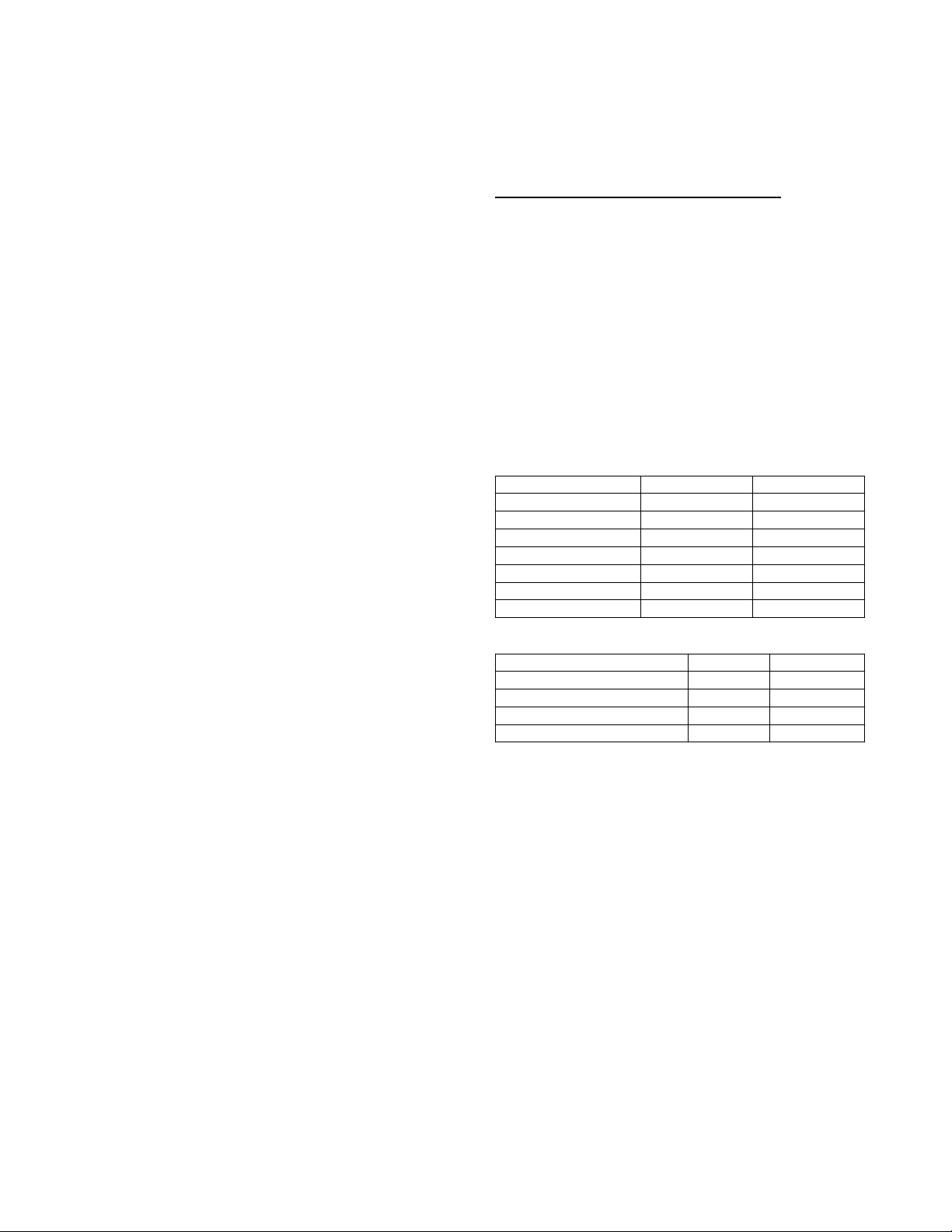
switches normal state. Table 6 shows the configurabl e functions and
what their normal and active states are. Ta ble 7 shows the configurable
analog input f unctions. The switch configurati ons can be found in the
SETTINGSUNIT CONFIGURATIONSSWITCH INPUT
CONFIGS sub--menu. The a nalog input configurati ons can be found
in the SETTINGUNIT CONFIGURATIONSSWITCH INPUT
CONFIGS sub--menu. The configurable input assignment can be
viewed in the SERVICEHARDWAREASSI GNED
INPUTS/OUTPUTS sub--menu.
Table 6 – Configurable Switch Input Functions
Function Description Normal State Active State
Humidistat OFF ON
Condensate Overflow LOW HIGH
Filter Status Switch CLEAN DIRTY
Remote Occupancy UNOCC OCCUPIED
Remote Shutdown RUN SHUTDOWN
General Status Switch GOOD ALARM
Enthalpy Switch Input LOW HIGH
Table 7 – Configurable Analog Input Functions
Function Description Sensor Type Sensor Values
Space Air Relative Humidity Sensor 0 --- 2 0 m A %RH
Return Air Relative Humidity Sensor 0 --- 20mA %RH
Indoor Air CO2Sensor 0 --- 20m A PPM
Outside Air CO2Sensor 0 --- 2 0 m A CFM
General Operation
48/50LC units can provide cooling, dehumidification, heating, and
ventilation. The operating mode (MODE) shows the highest level
of operation of the unit at any given time. The operating sub--mode
(SUB--MODE) shows the detail operation occurring while under a
specific mode. Fig. 10 shows the MODE and SUB--MODE values.
Each unit will operate under one of three basic types of control,
thermostat, space temperature sensor, or return air temperature
sensor. There are many inputs, configurations, safety factors, and
conditions that ultimately control the unit. Refer to the specific
operation sections for detail on a specific unit operation. The
control will set the demand based on these types of control and
conditions, which then drives the operating mode.
When thermostat control is enabled (UNIT CONTROL TYPE),
the unit will operate based on discrete input commands (G, Y1,
Y2, Y3, W1, and W2) and there is a one minute time delay
between modes and when re--entering a mode. The G command
calls for ventilation, the Y1, Y2, and Y3 commands call for
cooling, and the W1 & W2 commands call for heating. Thermostat
Control Type (THERMOSTAT TYPE) affects how cooling
operates based on Y1, Y2, and Y3 commands and if
cooling/heating stage time guards are applied.
When space temperature sensor control in enabled (UNIT
CONTROL TYPE), the unit will try to maintain the Space
Temperature (SPACE TEMPERATURE) between the effective
13
Page 14
cool and heat setpoints (EFF COOL SETPOINT and EFF HEAT
SETPOINT). However, to minimize unnecessary cool to heat and
heat to cool changes, there is a 10 minute delay after the last stage
turns off before the control will switch modes. Linkage operation
overrides the mode changeover delay to 15 seconds. The cooling
and heating Mode Select Time guards (COOL MODE T.GUARD
and HEAT MODE T.GUARD) show the remaining time before
allowing the respective mode to be entered.
Demand Determination
Based on the unit control type (UNIT CONTROL TYPE),alarm
overall demand of the unit. Table 8 shows the possible system
demands with their priority level and summary description.
Thermostat Demand
When the unit control type is configured for thermostat (UNIT
CONTROL TYPE = TSTAT) the level 5 demand in Table 8 will be
determined by thermostat inputs and the Thermostat Type
configuration (THERMOSTAT TYPE) as shown in the tables
below. Table 9 shows the cooling thermostat inputs and how they
map to the system demand. Table 10 shows the heating thermostat
inputs and how they map to the system demand.
conditions, and user interaction, the control will determine an
MODE OFF VENT COOL HEAT TEST
STARTING UP MODE TIMEGUARD ECON FREE COOLING HEATING MANUAL TEST
SUB-
MODE
IDLE - NO DEMAND
MODE TIMEGUARD MECH. COOLING
UNIT DISABLED ECON/MECH COOLING
URGENT SHUTDOWN DEHUMIDIFICATION
SAFETY CONTROL DEHUM/MECH COOL
SUPPLY FAN ON UNOCC. FREE COOL
DEHUM PREVENTED
COOLING PREVENTED
SHUTTING COOL OFF
OUTSIDE AIR TEMPERING
HEATING PREVENTED
SHUTTING HEAT OFF
AUTO TEST
SHUTTING TEST OFF
Fig. 10 -- Modes and Sub--Modes
a48--- 9374
Table 8 – Demand List and Priority
DEMAND Priority Description
EMERGENCY 1 An emergency condition occurs which requires a unit shutdown
SAFETY FAULT 2 A safety diagnostic requires the unit to run in safety mode.
SERVICE TEST 3 User request test mode
SHUTDOWN 4 A minor or user condition requires the unit to shutdown
NO DEMAND
FAN ONLY O nly circulation or ventilation is requested form the building
DEHUM A dehumidification load is present in the building
LOW COOL A low cooling load is presen t in the building
MED COOL A medium cooling load is present in the building
HIGH COOL A high coolin g load is presen t in the building
LOW COOL & DEHUM A low cooling and dehumidification load is present in the buil ding
MED COOL & DEHUM A medium cool ing and dehumidification load is present in the building
HIGH COOL & DEHUM A high cooling and dehumidification load is present in the buil ding
UFC LOW COOL A low cooling load is present in the building due to the unoccupied free cooling algorithm
UFC MED COOL A medium cooling load is present in the building due to the unoccupied free cooling algorithm
UFC HIGH COOL A high cooling load is present in the building due to the unoccupied free cooling algorithm
LOW HEAT A low heating load is present in the building
HIGH HEAT A high heating load is present in the bu ilding
SUPPLY AIR TEMPERING Due to outside air, supply air is uncomfortably cool during ventilation
5
There is no comfort demand from the building
Table 9 – Thermostat Cooling System Demands
Thermostat Inputs THERMOSTAT TYPE
Y1 Y2 Y3 CONV 2C2H** CONV 3C2H DIGI 2C2H* DIGI 3C2H
0 0 0 No Cool No Cool No Cool No Cool
0 0 1 No Cool Alert & Low Cool No Cool High Cool
0 1 0 Alert & Low Cool Alert & L ow Cool Medium Cool Medium Cool
0 1 1 Alert & Low Cool Alert & Med Cool Medium Cool High Cool
1 0 0 Low Cool Low Cool Low Cool Low Cool
1 0 1 Low Cool Alert & Med Cool Low Cool High Cool
1 1 0 High Cool Medium Cool High Cool Medium Cool
1 1 1 High Cool High Cool High Cool High Cool
*Y3isignored
** Set the LOW COOL COMP as needed, and Y3 is ignored
14
Page 15
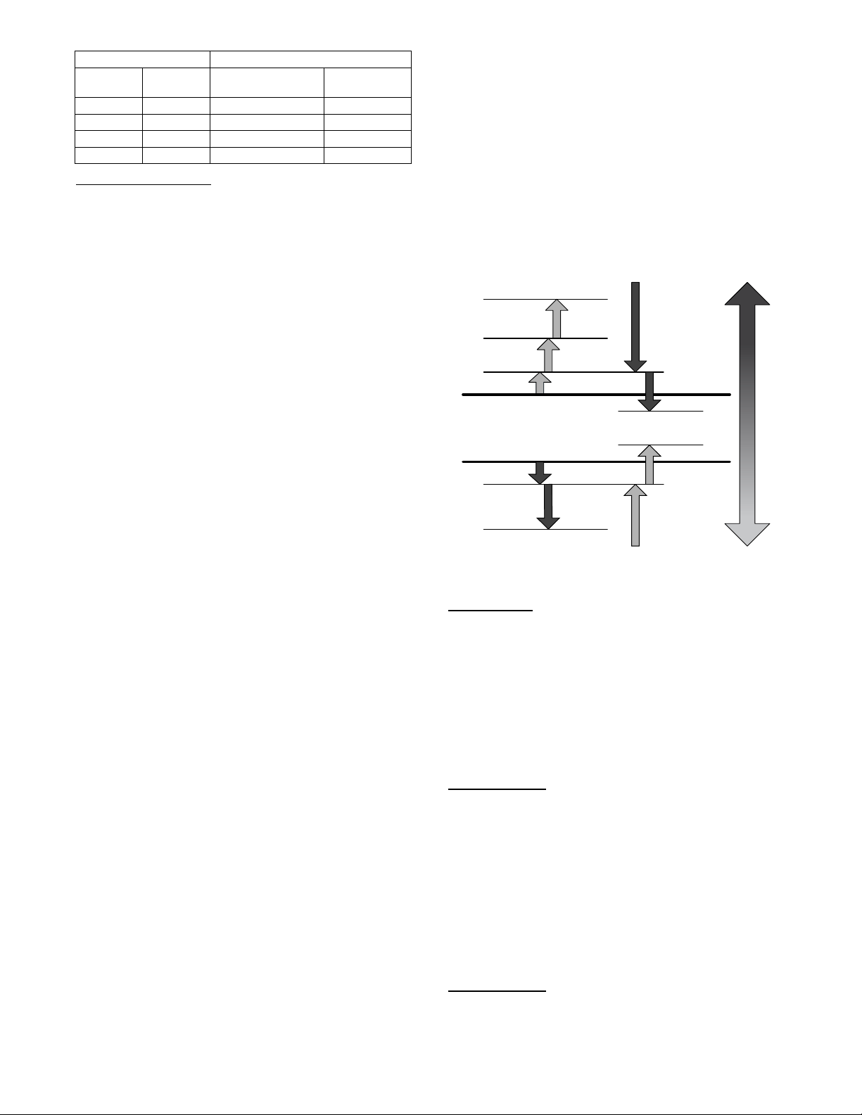
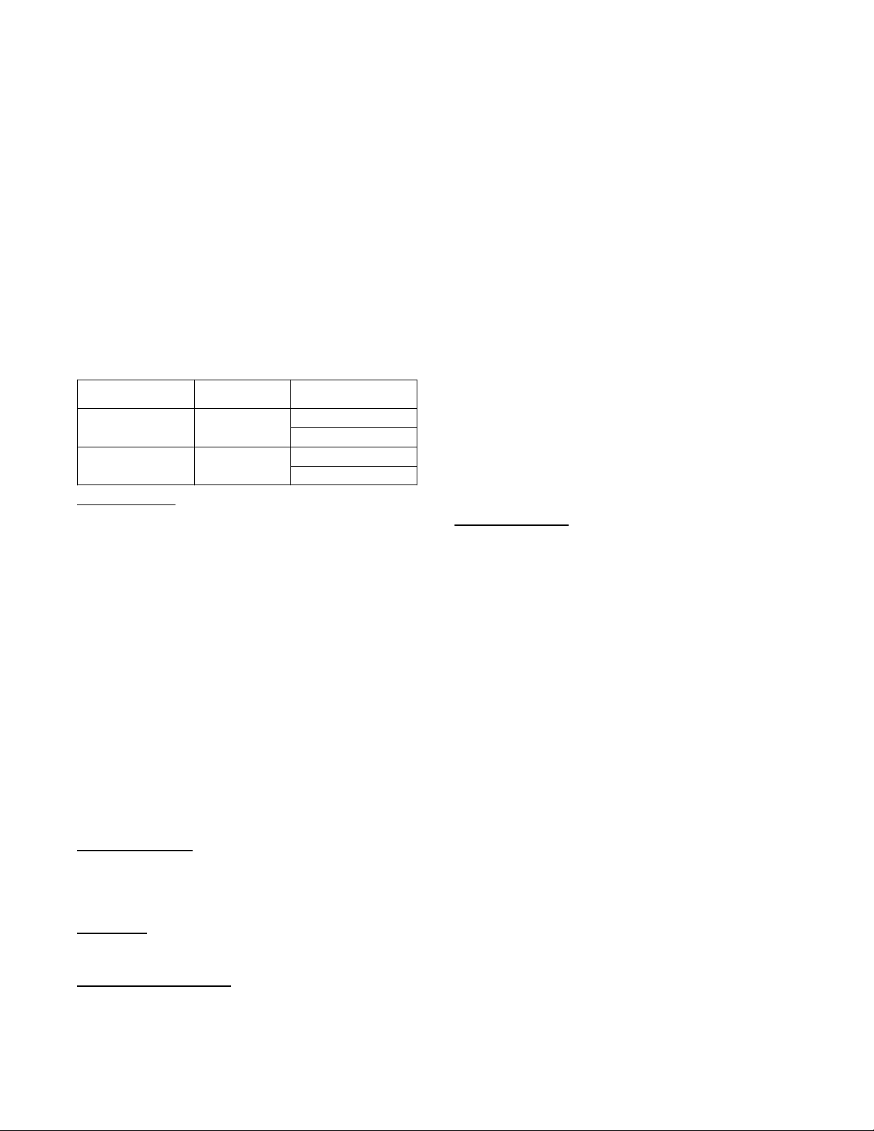
Table 10 – Thermostat Heating System Demands
Thermostat Input THERMOSTAT TYPE
W1 W2
0 0 No Heat No Heat
0 1 Alert & Low Heat High Heat
1 0 Low Heat Low Heat
1 1 High Heat High Heat
CONV 2C2H
CONV 3C2H
DIGI 2C2H
DIGI 3C2H
Space Sensor Demand
When the unit control type is configured for space sensor (UNIT
CONTROL TYPE = SPACE SEN) the level 5 demand in Table 8
will be determined by the space sensor inputs and setpoints as
described below. The Effective Demand Temperature (DEMAND
CTRL TEMP) represents the temperature which the control is
using to control the space. This would come from the space sensor,
building network, linkage, or the return air sensor.
Setpoint Determination
Setpoints are used to control the unit. The Cool Setpoint in Effect
(EFF COOL SETPOINT) and the Heat Setpoint in Effect (EFF
HEAT SETPOINT) are the points in which the unit is controlling
to at a specific time. These points are read only points and change
according to occupancy, the offset slider status, and network writes.
The setpoint configurations are in the SETTINGSSPACE SET
POINTS submenu.
If the building is in occupied mode, the Occupied Cool Setpoint
(OCC COOL SETPOINT) and the Occupied Heat Setpoint (OCC
HEAT SETPOINT) are active. When the building is in
unoccupied mode, the Unoccupied Cool Setpoint (UNOCC COOL
SETPNT) and the Unoccupied Heat Setpoint (UNOCC HEAT
SETPNT) are active. The heating and cooling set points are also
separated by a Heat--Cool Set Point Gap (HEAT-COOL SP GAP)
that is user configurable from 2 to 10 degrees F. This parameter
will not allow the setpoints to be set too close together, it will
change the last setpoint adjusted if it is set within the GAP.
When the space sensor has a setpoint slider adjustment, the cool
and heat setpoints (occupied) can be offset by sliding the bar from
one side to the other. The SPT Offset Range (+/--) (SPT SLIDER
RANGE) sets the total positive or negative degrees that can be
added to the setpoints. With the slider in the middle, no offset is
applied. Moving the slider to the “COOL” side will subtract from
each setpoint, and sliding it to the “WARM” side will add to the
setpoints. The slider offset being applied at any given time is
displayed as Space Temperature Offset (SLIDER OFFSET VAL).
Temperature Demand
Space sensor staging control is an adaptive anticipation control that
weighs the actual space demand against the trend of that demand.
The control tries to anticipate the change in the space because of its
current stage status. This anticipation is based on the demand
trends. These trends will show the control how the space is reacting
to the current running conditions and help it decide when to
change the actual demand of the system. The following points are
in the RUN STATUSMODE submenu:
COOLING DEMAND — This is the difference between the Cool
Setpoint in Effect (EFF COOL SETPOINT) and the Effective
Demand Temperature (DEMAND CTRL TEMP) representing the
demand of the space for cooling.
COOL DEMAND TREND — This is the rate of change of the
cooling demand in degrees per minute, representing how the space
is changing its demand for cooling.
HEATING DEMAND — This is the difference between the Heat
Setpoint in Effect (EFF HEAT SETPOINT) and the Effective
Demand Temperature (DEMAND CTRL TEMP) representing the
demand of the space for cooling.
HEAT DEMAND TREND — This is the rate of change of the
heating demand in degrees per minute, representing how the space
is changing its demand for cooling.
In general the system demand will increase based on the demand
compared to the demand switch states in Fig. 11. The demand
cannot increase until Time guard 1 (DEMAND TIMEGUARD1)
expires. The LCON and LHON thresholds will also cause the
system demand to be reduced. When the demand hits the off switch
stages the system demand will be set to NO DEMAND. These
switch stages are in the SETTINGSSET POINTS
TEMP
DEMAND CONFIG submenu.
The cooling and heating demand level up configurations (COOL
DMD LEVEL UP and HEAT DMD LEVEL UP) will restrict a
system demand increase if the demand trend is less than the level
up configuration. These level up configurations will also increase
the system demand if the demand trend is greater than it for greater
than the T ime guard 2 (DEMAND TIMEGUARD2).
The system demand will increase if it has remained at the same
state for greater than Time Guard 3 (DEMAND TIMEGUARD3).
HCON
MCON
LCON
Cool Setpoint
Heat Setpoint
LHON
HHON
Decrease
Demand
LCOF
LHOF
Decrease
Demand
SPACE TEMP
C14323
Fig. 11 -- Space Sensor System Demand Switch States
RA T Demand
When the unit control type is configured for return air sensor
(UNIT CONTROL TYPE = RAT SEN) the level 5 demand in
Table 8 will be determined the same as space sensor but using the
return air temperature (RETURN AIR TEMP) instead of the space
temperature (SPACE TEMPERATURE).
Occupancy Determination
The building’s occupancy is affected by a number of different
factors. Occupancy affects the unit set points and the operation of
the economizer. The factors affecting occupancy are listed below
from highest to lowest priority.
Level 1 Priority
Level 1 classification is a force/write to occupancy and can occur
two ways. Listed in order of priority: force on OCCUPIED, and a
Linkage write. The CCN point OCCUPIED is forced via an
external device such as a ComfortIDt controller or a service tool:
when OCCUPIED is forced to YES, the unit is considered
occupied, when OCCUPIED is forced to NO, the unit is
considered unoccupied. If the unit is being controlled by Linkage,
the occupancy is communicated and mapped to OCCUPIED as an
input. Linkage does not force the point only write to it, therefore a
force applied to OCCUPIED will override it.
If OCCUPIED is not being forced or written to, proceed to the
level 2 priority.
Level 2 Priority
Level 2 is considered occupant interaction, and consists of Timed
Override and Remote Occupancy Switch. A timed override button
press will override a remote occupancy switch if both are installed
for operation.
15
Page 16
While using the programmed schedule, occupancy can be
temporarily switched from unoccupied to occupied by pressing the
override button for approximately 3 seconds on the T--55, T --56, or
T--59 space temperature sensor. The length of the override period
when pressing the override button is determined by the Override
Time Limit (TIMED OVR LENGTH). The hours remaining in
override is displayed as Timed Override Hours (TIMED OVR
HOURS). This point can also be changed from the local display or
network to set or change the override period length.
Remote Occupancy Switch (REMOTE OCC SWITCH) can be
forced or configured for operation based on an actual switch. The
physical switch should be configured to either Normally Open or
Normally Closed when the user would like to control the
occupancy with an external switch. This switch is field--supplied
(24v, single pole, single throw [SPST]). There are two possible
configurations for the remote occupancy switch:
1. (REMOTE OCC TYPE = 0) Normally Open Switch
1. (REMOTE OCC TYPE = 1) Normally Closed Switch
If the switch is configured to No Switch (REMOTE OCC CHAN =
None), the switch input value will be ignored and software will
proceed to level 3 priority. For each type of switch, the appropriate
configuration and states are listed in the table below.
TYPE OF SWITCH
Occupied when Closed
or Unoccupied when
Open
Occupied when Open or
Unoccup ied when
Closed
SWITCH
CONFIGURATION
Normal Open (0)
Normal Closed (1)
STATE OF SWITCH AND
STATE OF OCCUPANCY
Open and Unoccupied
Closed and Occupied
Open and Occupied
Closed and Unoccupied
Level 3 Priority
The following occupancy options are determined by the state of
Occupancy Schedule Number (SCHEDULE NUMBER) and the
Global Schedule Broadcast (BROADCAST SCHEDL?).
1. (SCHEDULE NUMBER = 0) The unit is always
considered occupied and the programmed schedule is
ignored. This is the factory default.
2. (SCHEDULE NUMBER = 1 - 64) Follow the local
programmed schedule. Schedules 1 to 64 are local within
the controller. The unit can only store one local schedule
and therefore changing this number only changes the title of
the schedule table.
3. (SCHEDULE NUMBER = 65- 99) Follow the global
programmed schedule. If the unit is configured as a Global
Schedule Broadcaster (BROADCAST SCHEDL? = YES),
the unit will follow the
unit s programmed schedule and
broadcast the schedule so that other devices programmed to
follow this schedule number can receive the schedule. If the
unit is not programmed as a Global Schedule Broadcaster
(BROADCAST SCHEDL? = NO), the unit will receive
broadcasted schedules from a unit programmed to broadcast
this schedule number.
Humidity Demand
When the unit is configured for either a Humidistat input
(HUMSTAT CHANNEL) or Space Humidity Sensor (SPRH
SENS CHANNEL) the level 5 demand in Table 8 will include a
determination of dehumidification demand.
Humidistat
When receiving an active input from the Humidistat
(HUMIDISTAT), dehumidification will be demanded.
Space Relative Humidity
On units with a relative humidity sensor, when the received value
of space relative humidity (SPRH LEVEL) has exceed the
humidity set point (SPRH SET POINT), dehumidification will be
demanded. This demand will remain until the space relative
humidity has fallen below the humidity set point by more than the
humidity set point deadband (SPRH DEADBAND). This would
come from the space humidity sensor, or building network.
Indoor Fan Operation
These units use the Staged Air Volume (SAV) method of controlling
the supply fan for a typical constant volume rooftop unit. This control
method employs a variable frequency drive (VFD) to operate the
supply fan at different speeds in order to achie ve energy savings
through reduce d fan power. This method is specifi cally not concer ned
with controlling static pressure in the supply duct, but rather with
setting different fan speeds for different operating condit i ons, suc h as
ventilation mode or part--load mechanical cooling.
The SAV function is NOT a Variable Air Volume (VAV) function.
The fan adapts its speed to one of eight based on mode and current
state to satisfy a demand. The eight speeds consist of off (0%) and
seven configurable values. The seven configurable fan speeds are:
Maximum Speed (MAXIMUM IDF SPEED), Ventilation (VENT
IDF SPEED), Heating (HEATING IDF SPD), Free Cool (FREE
COOL IDF SPD), Mechanical Low Cooling (LOW COOL IDF
SPD), Mechanical Medium Cooling (MED COOL IDF SPD),and
Mechanical High Cooling (HIGH COOL IDF SPD),TheVFDis
powered direct from the distribution block or circuit breaker (CB)
and is always on with power applied unless the CB is tripped.
When the thermostat or space sensor control conditions require the
fan on, the VFD will then ramp to desired speed. Fan speed is
always calculated by evaluating the current applicable conditions.
Each fan speed condition is evaluated independently, and the
highest fan speed is used. For example, if a cooling call occurs
during Ventilation mode, the unit mode will transition to cooling
but the fan speed is set to the higher of the two (VENT IDF
SPEED or LOW COOL IDF SPD). Refer to the speed
configurations below for when the fan will run at them.
Direct Drive Units
Alternately, 48/50LC04--06 units can have either a direct drive
Electronic Commutated Motor (ECM) fan system or a belt drive
motor powered by a Variable Frequency Drive (VFD). And
IDFTYPE=1 indicates a unit with VFD, while an IDFTYPE=2
indicates a direct drive system. Refer to the unit product data for
Fan Performance tables and physical data. On direct drive units, the
ECM has 5 speed taps to allow a range of fan performance. The
control has 3 output wires to connect to 3 different taps. From the
factory the low and high speed wires are connected to the first and
second speed taps, respectively. The ventilation speed tap is
disconnected. The speed taps increase the speed the higher the tap
number, so the first tap is the lowest speed and tap 5 is the highest
speed. If the low and high speed wires are moved to higher taps,
the ventilation speed wire can be wired into the motor. To activate
the use of the ventilation speed wire, the Number of Speeds
(SETTINGSUNIT CONFIGURATIONSINDOOR FAN
NUMFSPDS) configuration must be set to 3.
The Commanded Fan Speed (OUTPUTSINDOOR
FANF ANSPEED) repr esents the controls commanded speed for
the fan at any given time. This commanded speed is determined by
the unit’s curr ent HVAC mode and the unit control type. For gas
heating units, the IGC fan request output (InputsGEN. IIGC.F) is
monitored by the control. This can result in additional modification of
fan delays or other operation due to safety functions of the IGC
control. See the Gas Heating operation section for more details. If
configured for IAQ fan ope ration, the fan may be tur ned on to satisfy
air quality demands. See the Indoor Air Quality section if using IAQ
(indoor air quality) accessory sensors. The fan can run under
therm ostat or spa ce sensor control and will re main on if com pressors
or heat rela ys are ever stuck on. If Shut Down on IDF Failure is
enabled (SHUTDOWN IDF FAIL = Yes) , the fan and unit will be
shutdown wi thout del ay on fan a larm conditions. Fan off delays are
honored when exiting specific HVAC modes. The Fan-- off Delay
delays are as follows: Cooling (COOL FANOFF DELAY), and
Heating (HEAT F ANOFF DELAY).
16
Page 17

Indoor (Supply) Fan Maximum Speed
(MAXIMUM IDF SPEED)
Max speed is the highest fan speed allowed. This is typically 100%
when pulleys are set to deliver design CFM to the space per job
requirement. Most safety conditions for the unit will override the
fan speed to this to help protect the unit.
Ventilation Indoor Fan Speed (VENT IDF SPEED)
This configuration defines the fan speed used in Ventilation
(fan--only) mode. Ventilation mode is when the supply fan is
running, but there is no demand for heating or cooling. In
thermostat mode, this is with just a G call. In space sensor control,
this is when the unit is Occupied mode and the indoor fan is
configured to always run while occupied (OCCUPIED FAN?).If
the indoor fan is configured for intermittent fan (OCCUPIED
FAN? = No), the Mode will be off instead of Ventilation and the
fan will not run unless a heating or cooling mode is needed. During
the unoccupied period, the fan will always operate intermittently.
The economizer damper will adjust its position based on how far
away this speed is from max speed for ventilation.
IMPORTANT: It is important that the ventilation rate is checked after
setting this speed to verify that the unit can properly ventilate the space
per requireme nt s. Adjusting this configur ation or the economiz er
minimum setting curve should be performed to meet job requirements.
Heating Indoor Fan Speed (HEATING IDF SPD)
This configuration defines the fan speed used when in heating
mode and running heat. On units equipped with Gas heat (UNIT
TYPE OF HEAT), this heat speed will be delayed on based on the
IGC’s fan on call (IGC FAN REQUEST). Once the IGC request
the fan the fan will run what this heating speed configuration is set
for until heating is ended. On units configured for Electric heat
(UNIT TYPE OF HEAT) and configured for Preheat without the
fan (PREHEAT W/O IDF), this heat speed will be delayed on
based on the Preheat fan delay time (PREHEAT FAN DELAY).
Once this preheat time has expired or not configured for preheat,
the fan will run at this heat speed while heat is on.
Free Cooling Indoor Fan Speed (FREE COOL IDF SPD)
This configuration defines the initial fan speed used when in Free
Cooling. Refer to the Economizer Controls Operation section for
details on free cooling. The fan will stay at this configured speed
whenever only the damper is being used for free cooling. If the
damper is at 100% for 5 minutes the fan will ramp to the high
cooling speed. It is locked there until the actual damper position
falls below 75% at which time it will ramp back down to this
configured speed.
Low Cooling Indoor Fan Speed (LOW COOL IDF SPD)
This configuration defines the fan speed used when only one stage
mechanical cooling is being performed.
Medium Cooling Indoor Fan Speed (MED COOL IDF SPD)
This configuration defines the fan speed used when only second
stage mechanical cooling is being performed.
High Cooling Indoor Fan Speed (HIGH COOL IDF SPD)
This configuration defines the fan speed used when third (full load)
stage mechanical cooling is being performed. When performing
integrated cooling with the economizer this speed will be used. When
only free cooling with a high cool demand, this spee d will be used.
Cooling Operation
The 48/50LC unit’s cooling operation consists of: demand and
mode determination, staging request to satisfy the demand, and
handling a request with the unit’s resources. These resources can
include compressors, Humidi--MiZer
fan speed based on options. This section covers mechanical
cooling. For economizer free cooling, refer to the Economizer
Operation section (starting on page 24).
For Humidi--MiZer system operation, refer to the Optional
Humidi--MiZer Dehumidification System section (see page 19).
R
system, an economizer, and
Cooling Mode Control
The cooling HV A C mode (OPERATING MODE) has 9 different
operating sub modes (SUBMODE): ECON FREE COOLING,
UNOCC. FREE COOL, MECH. COOLING, ECON/MECH
COOLING, DEHUMIDIFICATION, DEHUM/MECH COOLING,
DEHUM PREVENTED, COOLING PREVENTED, and
SHUTTING COOL OFF. These are all part of a general cooling
mode and rese mble the specific type of cool ing that is being
performed at any given time. All types of cooling are still performed
under the general cooling function, and the expanded text i s for user
reference only.
For the unit to enter cooling mode, three things must be true: the
indoor fan must be ok t o use, the mode c hangeover time guard must
be expired, and there must be a cooli ng or dehumidification demand
(Y1, Y2, Y3, space cool demand, or humidity demand). The unit will
rema in in cooling for at least one minute or until any of the above
conditions turn false. The cool ing mode does not offici ally e nd until
the compress or is off and the fan off delay has expired.
Cooling Staging Control
Once the unit is in a cooling mode, determine what the demand is
and how to satisfy it. If an economizer is installed and can be used
for cooling (OK TO USE FREE COOLING? = Yes), the unit will
use it first (see economizer section for its operation). If the
economizer cannot be used or additional cooling is needed, a
mechanical cooling check is performed. OK to use Compressors?
(OK TO USE COMPS?) will be set to yes when the outdoor
temperature (OUTDOOR AIR TEMP) is above the Circuit A
Lockout temperature (CIR.A LOCKOUT OAT) and the Circuit A
is not locked out for diagnostic reasons (CIRCUIT A LOCKOUT).
Based on the unit control configuration, requested cooling stages
(REQ. COOL STAGES) will be determined then passed to
compressor control to actually add the cooling stages.
There are two ways of requesting stages when thermostat control is
enabled, Traditional thermostat control or adaptive control.
Traditional thermostat control is used if set for non--adaptive
thermostat (ADAPTIVE TSTAT = NO) and the unit cannot use the
economizer for free cooling. If set for adaptive thermostat
(ADAPTIVE TSTAT = YES) or any time the economizer is
available for free cooling, the unit will use adaptive control for
staging.
When configured for Space sensor or RAT control (UNIT
CONTOL TYPE) the unit will use adaptive control for staging.
With either staging method there are two supply air temperature
limits that apply, one restricts more cooling stages and the other
will remove cooling stages. If at any time the Supply--Air
Temperature (SUPPLY AIR TEMP) falls below the Minimum
Supply Air Temperature Upper Level (UPPER MIN SAT),the
requested stages will not be allowed to increase. If at any time the
SAT falls below the Minimum Supply Air Temperature Lower
Level (LOWER MIN SAT), the requested stages will be reduced
by one. If these SAT limits are configured so that they are too close
together, the last stage might cycle rapidly, slowed only by its
minimum on and off-- time requirements.
Adaptive Control
Stage timers and Supply air trend apply when determining the
request for stages. The first request (REQ. COOL STAGES =1)
comes immediately when starting the staging process. The Cool
Stage Increase Time (COOL STAGEUP TIME) has to expire and
the Supply-- Air Trend (SUPPLY AIR TREND) has to be above
the cooling supply air trend level (COOL SATTREND LEV)
before another stage can be added. Requested stages will only be
allowed to increase as the actual system demand allows
(DEMAND). A “LOW COOL” demand will only allow one
requested stage, “MED COOL” two stages, and “HIGH COOL” 3
stages. The requested stages will be reduced if the cooling demand
is lowered or dropped completely, or if the supply air falls below
the lower level (LOWER MIN SAT).
17
Page 18
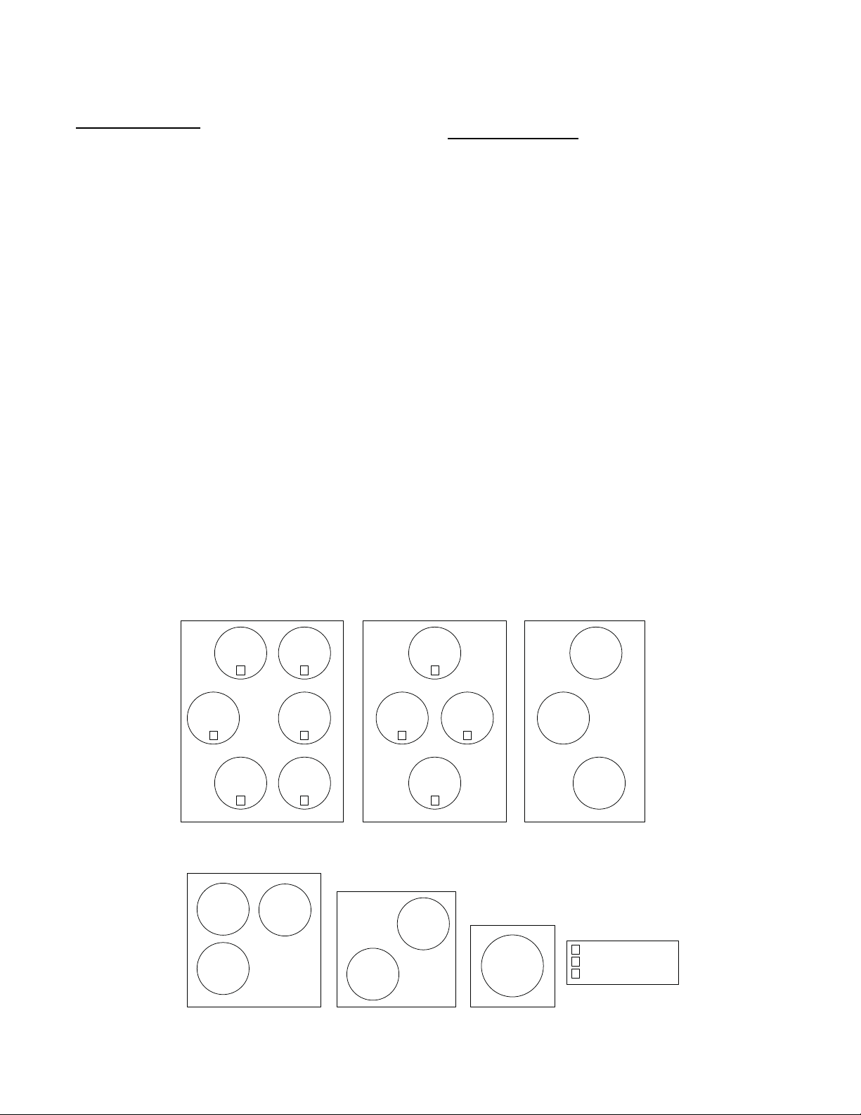
Traditional Thermostat Control
Stage timers and Supply a ir trend do not apply when determini ng the
request for stages. Request staging will follow the therm ostat input s
directly. “LOW COOL” will request one stage. “MED COOL” will
request two stages. “HIGH COOL” will reques t 3 stages.
Compressor Control
The compres sor control works hand and hand with the staging
control. As the staging c ontrol request stages, the c om pressor control
determines what is available or running and tries to provide stages for
what is requested. The availability of the compressors depends on time
guards, circuit diagnostics, a nd outdoor te mperature. The low cooling
compressor (LOW COOL COMP) informs the control which
compressor is desired for a low cooling demand.
IMPORTANT: When LOW COOL COMP is set to 2 the unit will
operate as a 2 stage unit where the larger compressor is stage one
and both compressors are stage 2.
There are time guards to protect the compressor, Compressor Min On
Time (COMP MIN ON TIME) and Compressor Min Off Time
(COMP MIN OFF TIME) apply before the compressors can be
turned back on or turned off. Time guard A1 (COMP A1
TIMEGUARD) and Timeguard A2 (COMP A2 TIMEGUARD)
display the time the compressors have before they can transition state.
Circuit diagnostic tests are performed during operation which may
or may not allow the compressors to be used. The availability of
the compressors is shown as Compressor A1 Available (COMP A1
AVAILABLE) and Compressor A2 Available (COMP A2
AVAILABLE). The lockout status of the compressors is shown as
Compressor A1 Lockout (COMP A1 LOCKOUT) and
Compressor A2 Lockout (COMP A2 LOCKOUT). The actual
stages running at any given time is displayed as Actual Cooling
Stages (ACTIVE COOL STAGE) :0 (Off), 1 (Compressor A1 On
only), 2 (Compressor A2 On only), and 3 (both compressors are
on). Individual compressor output state is shown as
(COMPRESSOR A1)and(COMPRESSOR A2).
Any t ime the out door ambie nt falls be low the low cooling minimum
outdoor tempera t ure (LOW COOL MIN OAT), the low cooling
lockout will be active (LOW COOL LOCKOUT) preventing
compre ssor A1 f r om running by itself. Any tim e the outdoor ambient
falls below the medium cooling minimum outdoor temperature (MED
COOL MIN OAT), the medium cooling lockout will be active (MED
COOL LOCKOUT) preventi ng com pressor A1 a nd com pressor A2
from running by themselves.
Outdoor Fan Control
Outdoor fans can be controlled by one of two methods: normal
operation of discrete speed based on the cooling being performed,
or low ambient operation that varies the outdoor airflow to control
saturated discharge temperature within an acceptable range. This is
implemented using multi--speed motors. The system outdoor fan
speed (COMMANDED ODF SPD) represents the commanded
speed of all outdoor fan motors as a complete system. The number
of outdoor fans in the system is determined by the Number of
outdoor fan outputs (ODF SIGNAL QTY).
IMPORTANT: The number of outdoor fans will not always match
the number of outdoor fan outputs (ODF SIGNAL QTY).Fig.12
shows how the outdoor fans are mapped with the outdoor fan
outputs.
NOTE: Factory default configurations account for these model
differences and should not be changed. The default configurations
have been qualified over a large range of conditions and are
provided in case a field replacement of a control board occurs and
the settings need to be checked or manually configured. Outdoor
fan operation is further described below to assist in
troubleshooting.
Typical Operation
When OAT is above low ambient temperature (LOW AMBIENT
TEMP), the ODFs will run at 4 dis crete speeds, off, Low Cool Speed
(ODF LOW COOL SPD), Medium Cool Speed (ODF MED COOL
SPD), and High Cool Speed (ODF HIGH COOL SPD),
corresponding to the 4 discr ete cooling stage of the compre s sors
(ACTIVE COOL STAGE): 0 (Off), 1 (Compressor A1 On only), 2
(Compre ssor A2 On only), and 3 (both compressors are on).
48/50LC 24-26 48/50LC 17-20 48/50 LC14
OFM3
1
OFM2
OFM1
1
Control Box Side
OFM5
2
OFM6
33
OFM4
2
OFM3
1
OFM1
1
OFM4
2
OFM2
OFM2
2
Control Box Side Control Box Side
48/50LC 08-12
48/50LC 07
OFM2
OFM3
Control Box Side
OFM1
OFM2
OFM1
Control Box Side
48/50LC 04-06
OFM
Control Box Side
Fig. 12 -- Outdoor Fan Motor Arrangement
OFM3
OFM1
Indicates the Outdoor
1
Fan Signal from the
2
board. Otherwise the
3
motor and signal match.
a48--- 9938
18
Page 19
Low Ambient Operation
Low ambient operation will be used when either of the 2
conditions is met: 1) OAT is less than low ambient temperature
(LOW AMBIENT TEMP) –5_F or 2) OAT is less than low
ambient temperature (LOW AMBIENT TEMP) –2.5_Fandthe
Saturated Discharge Temperature (CIR.A DIS. TEMP) is less than
92_F. The low ambient ODF control will manipulate ODF speed to
keep the discharge temp above 95_F. As OAT continues to drop,
ODF speed will continue to decrease, at certain point, the low
ambient control may decide to turn off ODFs and only control the
speed of the rest of the outdoor fans. If the discharge temp keeps on
decreasing, it may reach a point that all ODF fans will be turned
off. The ODFs will be turned on starting from the highest number
first, meaning the ODF1 will be the last one to shut off. The ODFs
are protected with a 45 second run time and a 60 second off time.
See Fig. 12 for the ODF arrangement. The lowest speed allowed to
run any ODF is determined by the outdoor fan Minimum Speed
Configuration (ODF MINIMUM SPEED).
NOTE: During ODF cycling all fans that are commanded on will
be at the same speed and the ones off will be at zero speed. The
motors will not be allowed to run different speeds at the same time.
When OAT ris es above low ambi ent te mperature (LOW AMBIENT
TEMP), ODF control will transition from low ambient to normal
operation. A period (5 min) is allowed for the ODF speed to ramp
from current position to one of the 4 discrete speed settings.
IMPORTANT: The low ambient temperature (LOW AMBIENT
TEMP) is default to 66 degrees and should not be changed unless
directed by authorized Carrier Personnel.
Optional Humidi--MiZerRDehumidificat ion System
Units with the factory--installed Humidi--MiZer system option are
capable of providing multiple modes of improved
dehumidification as a variation of the normal cooling cycle. The
Humidi--MiZer system option includes additional valves in the
liquid line and discharge line of each refrigerant circuit, a reheat
coil downstream of the evaporator, and variable--speed control of all
the outdoor fans . The Humidi--MiZer system equipped configurati on
is factory set to Yes for Humidi--MiZer system equipped units
(HUMIDIMIZER OK = YES). This enables Humidi--MiZer system
operating modes and service test.
Humidi--MiZer system operation requires the installa tion and
configuration of a relat ive humidi ty swit ch input or a space relative
humidity sensor . The HU M I D I S TAT and SPRH lea ds are provided
with quick connects. The Space Humidity Switch configuration,
SETTINGS UNIT CONFIGURATIONS SWITCH INPUTS
CONFIGS HUMSTAT CHANNEL identifies the normally open
or norma lly closed stat us of this input at hi gh hum i dity. The Space
RH Sensor configur ation, SETTINGS UNIT
CONFIGURATI ONS ANALOG INPUTS CONFI GS SPRH
SENS CHANNEL, identifi es to the channel number the sensor is
wired into.
Dehumidification Demand
When using a humidistat or switch input, the demand for
dehumidification is seen as Space Humidity Switch
(INPUTSSWITCH INPUTSHUMIDISTA T) bei ng Low or
High. A l ow value means hum i dity leve l i s good and a high value
means that dehumidification is needed.
When using an SPRH sensor, the demand is based on the Space
Humidity Sensor (INPUTSANALOG INPUTSSPRH) value
compared to the Space RH Setpoint (SETTINGSSPACE
SETPOINTSSPRH SETPOINT). If the Space Humidit y Se ns or
(SPRH) value is above the Space RH Setpoint (SPRH Setpoint), then
dehumidificati on is needed. If the Space Humidi t y Sensor (SPRH)
value is below the Space RH Setpoint (SPRH Setpoint) minus the
Space RH Deadband (SETTINGSUNIT CONFIGURATIONS
COOLINGSPRH DEADBAND), then dehumidification is no
longer needed.
NOTE: When there is a dehumidification demand, the economizer
damper position is limited to its minimum damper position.
Humidi--MiZer System Modes
With Humidi--MiZer system units there are two additional HVAC
modes available for the user: Dehumidification and Dehum/Mech
Cooling. Selection of the Dehum/Mech Cooling mode is
determined by the dehumidification demand and the cooling
demand. Table 11 shows the corresponding circuit mode and
output status for the different demand combinations.
Normal Cooling
For 48/50LC07--26 units, refrigerant flows from the outdoor
condenser through the de--energized 3--Way Liquid Diverter Valve
(LDV) to the expansion device bypassing the reheat condenser
coil. The Reheat Discharge Valve (RDV) is closed. (See Fig. 14.)
T abl e 11 – Humidi--MiZer System Control Modes -- Si zes 07--26
DEMAND AND MODE OUTPUTS 48/50LC 07---26 Valves
Space
Humidity
Low No Off Off Off
Low Yes Cool On Off
High Yes
High No Dehum On On
Circuit
Cooling
Demand
— – No power Off Off
Circuit
Mode
Dehum/Mech
Cooling
Circuit
Compressor
On On
LDV Valve
3 --- w a y
RDV Valve
2 --- w a y
Off
(closed)
Off
(closed)
Off
(closed)
Off
(closed)
On
(open)
For 48/50LC04--06 units, refrigerant flows from the outdoor
condenser and is diverted at the energized Reheat Liquid Valve
(RLV) and flows through the de--energized Cooling Liquid Valve
(CLV) to the expansion device bypassing the reheat condenser coil.
The RDV is closed.
Table 12 – Humidi--MiZer System Control Modes -- Sizes 04--06
DEMAND AND MODE OUTPUTS 48/50LC 04 - -- 06 Valves
Space
Humidity
Low No Off Off
Low Ye s Cool On
High Yes
High No Dehum On
Circuit
Cooling
Demand
— –
Circuit
Mode
No
power
Dehum/
Mech
Cooling
Circuit
Compresso r
Off
On
RDL
Valve
Off
(closed)
Off
(closed)
Off
(closed)
Off
(closed)
On
(open)
RLV
Valve
(open)
(open)
(closed)
(open)On(closed)
(open)On(closed)
CLV
Valve
Off
Off
Off
Off
Off
Off
(open)
Off
(open)
Off
(open)
Dehum/Mech Cooling (Subcooling Mode)
This mode increases latent heat removal and decreases sensible
cooling compared to normal cooling. For 48/50LC07--26 units,
refrigerant flows from the outdoor condenser, through the
energized 3--Way Liquid Diverter Valve (LDV) and through the
reheat condenser coil to the expansion device. The Reheat
Discharge Valve (RDV) is closed. (See Fig. 16.)
For 48/50LC04--06 units, refrigerant flows from the outdoor
condenser through the de--energized Reheat Liquid Valve (RLV)
and through the reheat condenser coil to the expansion device. The
Reheat Discharge Valve (RDV) and Cooling Liquid (CLV) are
closed. (See Fig. 15.)
19
Page 20
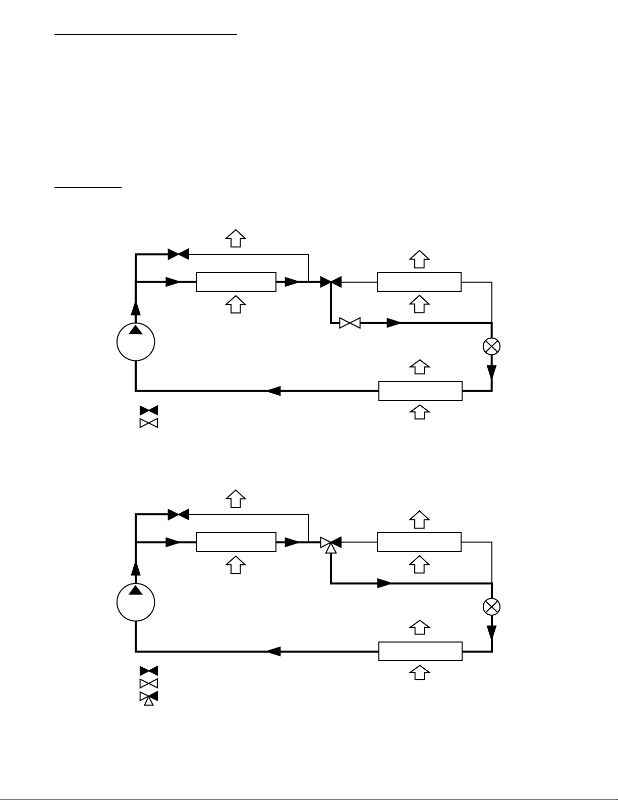
Dehumidification (Hot Gas Reheat Mode)
This mode provides maximum latent cooling with little to no
sensible capacity. This mode can operate to provide
dehumidification when there is no cooling demand. For
48/50LC07--26 the refrigerant flows from the outdoor condenser,
through the energized 3--Way Liquid Diverter Valve (LDV) and
through the reheat condenser coil to the expansion device. (See
Fig. 18.) For 48/50LC04--06 units, The refrigerants flows from the
outdoor condenser, through the de--energized RLV and through the
reheat condenser coil to the expansion device. The Cooling Lquid
Valve (CLV) is closed. For 48/50LC04--26 units the Reheat
Discharge Valve (RDV) is open which provides some compressor
discharge gas to the reheat condenser to further increase the reheat
of the evaporator air stream. (See Fig. 17.)
Reheat Control
When there is only a cooling demand, the unit will operate in
normal cooling mode. When there is only dehumidification
demand, the unit will operate in Dehumidification mode (Hot Gas
Reheat). When there is both cooling demand and dehumidification
demand, the unit will operate in Dehum/Mech Cooling mode
(Subcooling). During Dehumidification and Dehum/Mech cooling
mode, the unit will run all cooling stages. When the Outside Air
Temperature is above 80_F, the Outdoor Fans will run at maximum
fan speed. When the Outside Air Temperature is below 80_F, t he
Outdoor Fans will modulate to maintain Saturated Discharge
Temperature setpoint LA DEHUM LEV 1, LA DEHUM LEV 2
and LA DEHUM LEV, (SETTINGSUNIT
CONFIGURATIONSCOOLINGLOW AMBIENT. The unit
can be restricted from reheat operation by the outside temperature
HUMZ LOCKOUT OAT (SETTINGSUNIT
CONFIGURATIONS > COOLINGHUMZLOCKOUT OAT)
sets the lowest outside temperature the unit is allowed to run reheat
control (Default = 40_F).
RDV
VALVE
COMPRESSOR
= CLOSED VALVE
= OPEN VALVE
CONDENSER COIL
OUTDOOR AIR
RLV
VALVE
CLV
VALVE
INDOOR SUPPLY
HUMIDI-MIZER COIL
EVAPORATOR COIL
INDOOR RETURN
Fig. 13 -- Normal Cooling Mode – Humidi--MiZer System 48/50LC 04--06
RDV
VALVE
3-WAY
VALVE
CONDENSER COIL
INDOOR SUPPLY
HUMIDI-MIZER COIL
AIR
AIR
AIR
EXPANSION
VALVE
(TXV)
C14121
OUTDOOR AIR
COMPRESSOR
EVAPORATOR COIL
= CLOSED VALVE
= OPEN VALVE
= 3-WAY VALVE
INDOOR RETURN
Fig. 14 -- Normal Cooling Mode – Humidi--MiZer System 48/50LC 07--26
20
EXPANSION
VALVE
(TXV)
AIR
C14114
Page 21
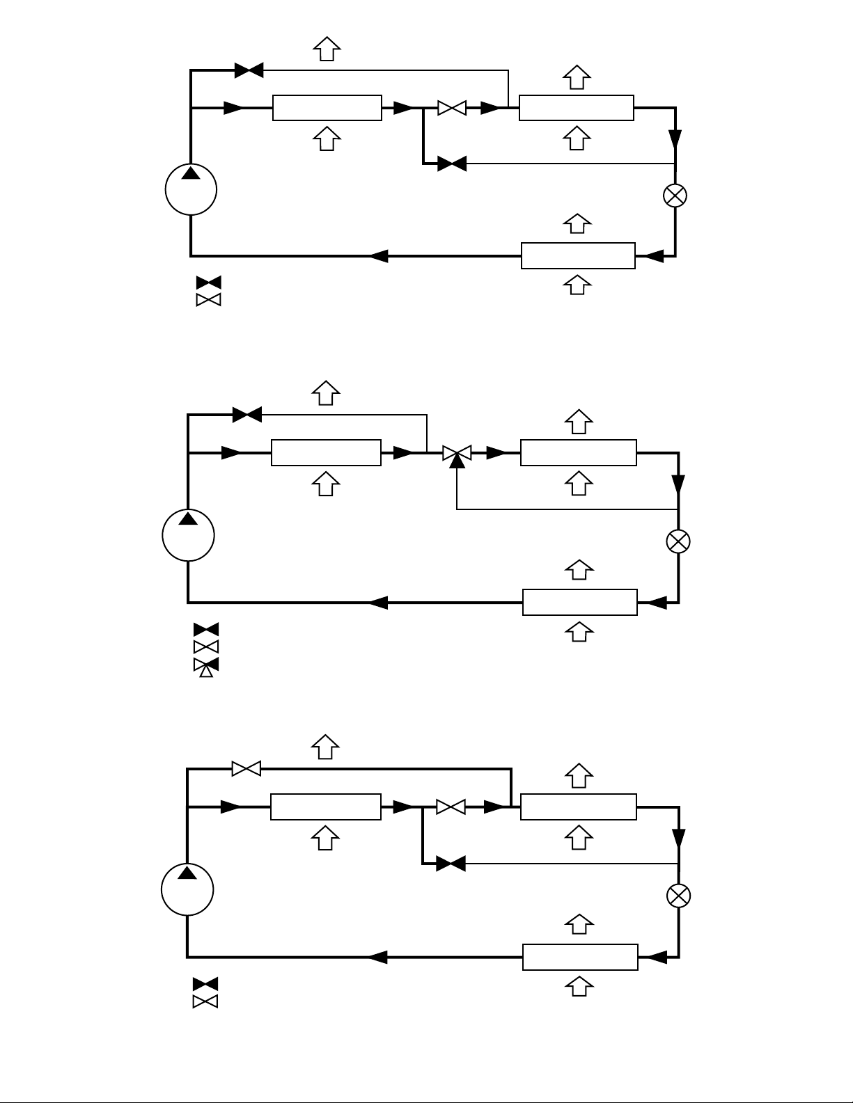
RDV
VALVE
INDOOR SUPPLY
AIR
HUMIDI-MIZER COIL
EVAPORATOR COIL
INDOOR RETURN
COMPRESSOR
= CLOSED VALVE
= OPEN VALVE
CONDENSER COIL
OUTDOOR AIR
RLV
VALVE
CLV
VALVE
Fig. 15 -- Subcooling Mode – Humidi--MiZerRSystem 48/50LC 04--06
RDV
VALVE
COMPRESSOR
CONDENSER COIL
OUTDOOR AIR
3-WAY
VALVE
INDOOR SUPPLY
HUMIDI-MIZER COIL
AIR
AIR
EXPANSION
VALVE
(TXV)
EXPANSION
VALVE
(TXV)
C14122
EVAPORATOR COIL
= CLOSED VALVE
= OPEN VALVE
= 3-WAY VALVE
INDOOR RETURN
Fig. 16 -- Subcooling Mode – Humidi--MiZerRSystem 48/50LC 07--26
RDV
VALVE
COMPRESSOR
= CLOSED VALVE
= OPEN VALVE
CONDENSER COIL
OUTDOOR AIR
RLV
VALVE
CLV
VALVE
INDOOR SUPPLY
HUMIDI-MIZER COIL
EVAPORATOR COIL
INDOOR RETURN
Fig. 17 -- Hot Gas Reheat Mode – Humidi--MiZer System 48/50LC 04--06
21
AIR
AIR
AIR
EXPANSION
VALVE
(TXV)
C14115
C14123
Page 22
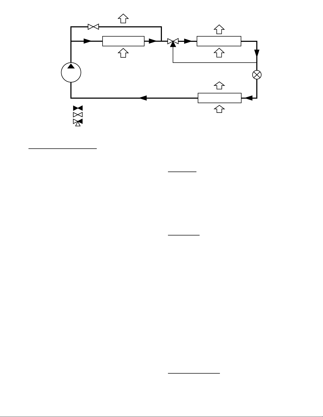
RDV
VALVE
CONDENSER COIL
OUTDOOR AIR
COMPRESSOR
= CLOSED VALVE
= OPEN VALVE
= 3-WAY VALVE
Fig. 18 -- Hot Gas Reheat Mode – Humidi--MiZer System 48/50LC 07--26
Reheat Mode Diagnostic Help
The status of reheat mode sensor inputs may be viewed within the
display INPUTS menu. The status of reheat mode outputs may be
viewed within the display OUTPUTS or RUN STATUSMODE
menu. Additional diagnostic help, including status of circuit reheat
temperature limit lockouts may be viewed within the
Humidi--MiZer sub --menu of the cooling mode diagnostic table at
RUN STATUSCOOLDEHUM. The Service Test mode may
be used to force the system to operate Dehumidification mode (Hot
Gas Reheat) and Dehum/Mech Cooling mode (Subcooling), or to
independently operate the reheat valve control outputs.
The following forced operating states are available service test
operations for a Humidi--MiZer system equipped unit:
SERVICE TEST COOL TEST HUMIDIMIZER TEST
LEVEL
A value of “0” sets reheat control test to “Off.”
SERVICE TEST COOL TEST HUMIDIMIZER TEST
LEVEL
A value of “1” sets Humidi-- MiZer control test to “Dehum/Mech
Cooling mode (Subcooling).”
SERVICE TEST COOL TEST HUMIDIMIZER TEST
LEVEL
A value of “2” sets Humidi--MiZer test to “Dehumidification mode
(Hot Gas Reheat).”
SERVICE TEST INDEPENDENTS LIQ DIVERT A TEST
A value of “On” will turn on the 3--Way Liquid Diverter V alve
(LDV).
SERVICE TEST INDEPENDENTS REHEAT A TEST
A value of “On” will turn on the Reheat Discharge Valve (RDV).
Indoor Fan Based Dehumidification
Belt Drive units that are not factory configured for Humidi--Mizer
operation can be set for improved dehumidification operation
UNIT
UNIT
through fan based humidification (FBD), SETTINGS
CONFIGURATIONS
COOLINGFBD TYPE. Units are
factory defaulted to FBD TYPE = 0 which means that any dehum
demand is ignored. There are two fan based dehumidification
options, Max Comfort (FBD TYPE = 1)andMax
Dehumidification (FBD TYPE = 2). Fan based dehumidification
requires the installation and configuration of either a space relative
humidity sensor or a relative humidity switch input. The Space
Humidity Switch configuration, SETTINGS
CONFIGURATIONS
SWITCH INPUTS CONFIGS
HUMSTAT CHANNEL identifies the normally open or normally
closed status of this input at HIGH humidity. The RH Sensor
INDOOR SUPPLY
AIR
3-WAY
VALVE
HUMIDI-MIZER COIL
EXPANSION
VALVE
(TXV)
EVAPORATOR COIL
INDOOR RETURN
AIR
C14116
configuration, SETTINGS
UNIT CONFIGURATIONS
ANALOG INPUTS CONFIGSSPRH SENSOR CHANNEL,
identifies the point on the MBB (Main Base board) or the IOB
(Input Output board) the sensor was wired into.
Max Dehum
When the FBD Type is set to (2) Max Dehum, the control will try to
satisfy the dehumidification demand. When the unit receives a dehum
demand a PID c ontrol a lgorithm will modula te the indoor fan while
the compressor is running to maintain minimum suction tem perature
(FBDH_SST). With a Y1 and dehum demand, t he unit wil l run the
compre ssor unloaded (48/50LC04--06) or will run the A1 compress or
only (48/50LC07--26). With a Y2 and de hum demand, the unit will
run with the compressor at full load (48/50LC04--06) or will run with
the A2 compressor only (48/50LC07--26). Wit h a Y3 and dehum
demand (48/50LC07--26 only), the unit will run both compre ssors.
Max Comfort
When the FBD Type is set to (1) Max Comfort, the control will try
to satisfy the dehumidification demand and minimize cold air
dump. When the unit receives a dehum demand a PID control
algorithm will modulate the indoor fan while the compressor is
running to maintain the minimum FBD supply air comfort set
point (FBDH_SAT) while also maintaining the minimum suction
temperature (FBDH_SST). With a Y1 and dehum demand, the unit
will run the compressor unloaded (48/50LC04--06) or will run the
A1 compressor only (48/50LC07--26). With a Y2 and dehum
demand, the unit will run with the compressor at full load
(48/50LC04--06) or will run with the A2 compressor only
(48/50LC07--26). With a Y3 and dehum demand (48/50LC07--26
only), the unit will run both compressors.
Heating Operation
The 48/50LC unit’s heating operation consists of: demand and
mode determination, staging request to satisfy the demand, and
handling a request with the unit’s resources. These resources can be
gas heat or electric heat. This section covers both gas heat units and
electric heat units. The Type of Heat Installed (UNIT TYPE OF
HEAT) configuration will be factory set to 1 for gas units and 0 for
electric heat units. The unit enters a heating mode based on a
demand, decides how to satisfy the demand, executes its plan, and
then leaves the heating mode.
Heating Mode Control
The heating HVAC mode (OPERATING MODE) has 3 different
operating sub modes (SUBMODE): HEATING, HEATING
PREVENTED, and SHUTTING HEAT OFF. These are all part of
a general heating mode and resemble the action heat mode is taking
22
Page 23

at any given time. All types of heating are still performed under the
general heating function, and the expanded text is for user
reference only.
For the unit to be allowed to enter the heat mode, three things must be
true: the indoor fan must be ok to use, the mode change over time
guard must be expired, and there must be a heating demand. The unit
will remain in heating for at least one minute and until the demand is
dropped or if any of the above conditions are false. The heating mode
does not officially end until all heat stages are off, the fan off delay has
expired, and the IGC fan request is dropped.
Supply--Air Temperature Sensor (SAT) Heat Mode
The SAT Heat Mode Sensi ng (SAT DURING HEAT?) informs the
unit that the supply ai r sensor has bee n reloca t ed downstream of the
heat section. This configur ation affe cts the Supply Air Te m pe rature
(SUPPLY AIR TEMP) value displayed as listed below.
When SAT DURING HEAT? is disabled, the Supply Air
Temperature (SUPPLY AIR TEMP) value on the SystemVut
display and the network will hold a zero when heat outputs come
ON and for 5 minutes after. The default SAT sensor location is at
the fan inlet, upstream of the heat section.
When SAT DURING HEAT? is enabled, the Supply Air Te mperature
(SUPPLY AIR TEMP) sensor reading is displayed at the SystemVu
controller and network during heating mode. This setting should only
be used if the original SAT sensor wires are removed from the Main
Base Board (MBB) and replaced by an accessory SA T sensor located
in the supply duct downstream of the heat section.
Heating Staging Control
Once the unit is in a heating mode, it determines what the demand
is and how to satisfy it. Requested Heating Stages (REQ. HEAT
STAGES) will be determined then passed to heat control to
actually add the heating stages. To request stages the number of
heat stages (HEATING STAGE QTY) must be greater than zero.
As a gas unit this will be set in the factory, however 50LC units
may have heat installed as accessories. If the Outdoor Air
Temperature (OUTDOOR AIR TEMP) is greater than the Heating
Lockout Temp (HEAT LOCKOUT OAT), all the heat stages will
be locked out (HEAT LOCKOUT).
There are two ways of requesting stages when thermostat control is
enabled, traditional thermostat control or adaptive control.
Traditional thermostat control is used if set for non--adaptive
thermostat (ADAPTIVE TSTAT = NO). If set for adapti ve thermostat
(ADAPTIVE TSTAT = YES), the unit will use adaptive control for
staging. When configured for space sensor or RAT control (UNIT
CONTOL TYPE) the unit will use adaptive control for staging.
With either staging method there are then two supply air
temperature limits, the Maximum SAT Lower Level (LOWER
MAX SAT) the Maximum SAT Upper Level (UPPER MAX SAT).
Any time the supply air temperature rises above lower level the
heat staging will be limited to what is currently on and no
additional stages will be added until the supply air temperature falls
back below the lower level. If the supply air temperature rises
above the upper level, then heating will be reduced by removing
one stage. That stage will not be added again until the Supply Air
Temperature falls below the lower level. If the supply air
temperature stays above the upper level, then another stage will be
removed. If the upper and lower levels are configured so that they
are close together, the last stage of heat might cycle rapidly, slowed
only by its minimum on and off-- time requirements.
Adaptive Control
Stage timers and Supply air trend apply when determining the
request for stages. The first request (REQ. HEAT STAGES =1)
comes immediately when starting the staging process. The Heat
Stage Increase Time (HEAT STAGEUP TIME) has to expire and
the Supply-- Air Trend (SUPPLY AIR TREND) has to be above
the Heating supply air trend level (HEAT SATTREND LEV)
before another stage can be added. Requested stages will only be
allowed to increase as the actual system demand allows
(DEMAND). A “LOW HEAT” will only allow one requested stage
and “HIGH HEAT” 2 stages. The requested stages will be reduced
if the heating demand is lowered or dropped completely, or if the
supply air falls below the lower level (LOWER MIN SAT).
Traditional Thermostat Control
Stage timers and Supply air trend do not apply when determining
the request for stages. Request staging will follow the thermostat
inputs directly. “LOW HEAT” will request one stage. “HIGH
HEAT” will request 2 stages.
Heat Relay Control
The he at relay contr ol is re sponsible for ene rgizing or de--energi zing
the heat stage relays and works hand and hand with the staging
control. As the stagi ng control requests stages , the hea t relay control
determines what actual heat relays are available or energized and tries
to provide stages for what is requested. The availability of heat relays
depends on the heat instal led, how many stages, and time guards. The
Number of Heat Stages (H EATING STAGE QTY) configuration tells
the control how many heat relays can be used. Heat Stage 1Timeguar d
(HEAT 1 TIMEGUARD) and Heat Stage 2 Timeguard (HEAT 2
TIMEGUARD) display the time a respective heat relay has before it
can change state. The available stages at a ny given t ime are displayed
as heat 1 available and heat 2 availabl e (HEAT 1 A VAILABLE and
HEAT 2 AVAI LABLE) . The actual heat relays on at any given time
are displayed as Actual Heating Stages (ACTVE HEAT STAGE) .
Heat Stage 1 Relay (HEAT 1 RELAY) and Heat Stage 2 Relay
(HEA T 2 RELAY) are displayed on when the respective relay is
energized. There are time guards to pr otect f r om short cycling, Heat
Minimum On Time (HEA T MIN ON) and Heat Minimum Off Time
(HEAT MIN OFF) apply before a heat relay can be turned back on
or turned off.
Integrated Gas Controller (IGC)
The heat staging is de termine d as describe d above and the Integrat ed
Gas Controller (IGC) initiates the gas heat module start--up. The
Integrated Gas Controller (IGC) minimum on-- time of 1 minute will
be followed even if Heat Minimum On Tim e ( HEAT MIN ON) is
lower and during Service Test. If the IGC temperature limit switch
opens within 10 minutes of the end of the gas heat cycle, the next fan
off delay wi ll be extended by 15 seconds . The maximum delay is 3
minutes. Once modified by t he IGC, the fan off delay will not change
back to the configured Fan--off Delay, Gas Heat (HEAT FANOFF
DELAY) unless power is reset to the control. A light emitting diode
(LED) is provide d on the IGC to indicate status . During normal
operation the LED is continuously on. See the Trouble shooting
section if the LED is off or fla shing. The IGC is located behind the
gas section access panel door.
When the control energizes Heat Stage 1 Relay (HEA T 1 RELAY),
power is sent to the W terminal on the IGC board. A check is made to
ensure that the rollout switch and limit switch are closed. The
induced --draft motor is then energized, and when speed is proven with
the Flue Gas Pressure switch on the motor, the ignition activation
period begins. The burners will ignite within 5 se conds. If the burners
do not light, there is a 22--second delay before another 5--second
attempt. If the burners still do not light, this sequence is repeated for
15 minutes. After the 15 minutes have elapsed, if the burners still have
not lit, heating is locked out. The control will reset when the request
for heat is temporarily removed. When ignition occurs the IGC board
will continue to monitor the condition of the rollout switch, limit
switches, the Flue Gas Pressure switch, as well as the flame sensor. If
the unit is controlle d through a room thermosta t or space sensor set for
auto--fan, 45 seconds after ignition occurs the indoor--fan motor will
be energized (and the outdoor--air dampers wil l open to their
minimum position). If for some rea son the over temperature limit
opens prior to the st art of the indoor fan bl ow er, on the next atte mpt,
the 45--second delay will be shortened to 5 sec onds less than t he time
from initiation of heat to when the limit tripped. Gas will not be
interrupted to the burners and heat ing will continue. Onc e modifie d,
the fan on delay will not change back to 45 se conds unl ess power is
reset to the control. When the control energizes Heat Stage 2 Relay
23
Page 24

(HEA T 2 RELAY), power is supplied to the sec ond stage of the main
gas valve. If both s tage 1 and stage 2 of the gas valve close, gas will
be turned off to the main burners.
Supply Air Tempering
Supply Air Tempering control operates the gas or electric heat to
maintain a minimum supply air temperature during conditions
where very cold outdoor air causes the supply air temperature to
fall below the configured Supply Air Tempering Setpoint. This
occurs during periods where DCV is active and increasing the
amount of outdoor air or in cases where the system is operating at
very low airflow and the calculated economizer position has
increased to maintain a constant ventilation rate.
The user can enable/disable Supply Air Tempering.
The following conditions must be true for the supply air tempering
algorithm to operate:
S The SA Tempering is set to Yes (OKTOSATEMPER=YES)
S The indoor fan is on
S The System Mode is in Vent (Ventilation or Supply Fan Only) or
IAQ Override.
S The Outdoor Air Temperature < Minimum Cooling SAT 48_F.
S Heat type is gas or electric and Number Of Heat Stages > 0
If all the above are true, the SystemVut controller will monitor the
SAT sensor value and operate the first stage of heat to temper the
supply air as required in order to maintain the configured SA
Tempering Setpoint
Economizer Operation
The Economizer is used for ventilation, and cooling. If the Indoor
fan is not on, the economizer will not operate. If an economizer is
installed, then Economizer Installed (ECON INSTALLED = YES)
should be set to YES. The unit produces a 4 --20mA signal which is
then changed to a 2--10V signal with a 500 ohm resistor, which can
control the economizer actuator. The economizer output signal is
displayed by the Economizer Commanded Position (ECON CMD
POSITION). The actuator’s built--in 2 to 10VDC feedback signal
is read in as an analog input to know the actual position which is
displayed as Economizer Actual Position (ECON ACT
POSITION).
Minimum Ventilation
The economizer will open to allow ventilation when the indoor fan
is turned on and the unit is in the occupied state. The economizer
damper position at any given time for ventilation is displayed as
the Min Position in Effect (EFFECTIVE MIN POS).This
minimum position can be effected by the indoor fan speed (F.SPD)
and indoor air quality. To maintain a constant airflow through the
economizer, as the indoor fan speed decreases or increases the
damper minimum position will increase or decrease, respectively.
This relationship curve is shown in Fig. 19.
NOTE: The software point names are used in Fig. 19 as to not
clutter the graph. These points are not individually set and
therefore only visible from a network for troubleshooting.
These units can also be equipped with optional CO
additional indoor air quality control. When unit is equipped with a
return duct CO
CO
sensor the Economizer minimum position vs. fan speed curve
2
will be recalculated based on the CO
outside air as shown in Fig. 19. When performing Demand
Controlled Ventilation, the damper’s Min Position in Effect
(EFFECTIVE MIN POS) will operate in the shaded area of Fig.
19 based on the IAQ Level (IAQ) and the Commanded Fan Speed
(IDF SPEED OUTPUT). See the Indoor Air Quality (IAQ)
section for more details on Demand Controlled Ventilation (DCV).
The damper position curve can be field adjusted per application if
needed.
sensor or return duct CO2sensor and outside air
2
level of the return and/or
2
sensors for
2
1. Activate test mode to control the fan and dampers to
achieve the correct numbers.
2. Set the fan speed for the maximum amount needed for
design CFM requirements. This should also be the IDF
maximum Fan speed (MAXIMUM IDF SPEED).
3. Open the damper to the position which satisfies the highest
ventilation requirement running maximum fan speed, and
then set the Economizer minimum at maximum fan speed
(MIN POS @ MAX FAN) to this damper position.
4. Set the fan speed to a realistic operating speed in the upper
range, and then set the User Minimum Position Speed 1
(MIN POS SPEED 1) equal to that speed. This should be
somewhere in the 80% range.
5. Open the damper to the position which satisfies the highest
ventilation requirement running speed 1 fan speed, and then
set the User Minimum Position Damper Position 1 (MIN
POS DAMP 1) to this damper position.
6. Set the fan speed to a realistic operating speed in the mid-range, and then set the User Minimum Position Speed 2
(MIN POS SPEED 2) equal to that speed. This should be
somewhere in the 60% range.
7. Open the damper to the position which satisfies the highest
ventilation requirement running speed 2 fan speed, and then
set the User Minimum Position Damper Position 2 (MIN
POS DAMP 2) to this damper position.
8. Set the fan speed to a realistic operating speed in the low-range, and then set the User Minimum Position Speed 3
(MIN POS SPEED 3) equal to that speed. This should be
lowest fan speed in planned operating range.
9. Open the damper to the position which satisfies the highest
ventilation requirement running speed 3 fan speed, and then
set the User Minimum Position Damper Position 3 (MIN
POS DAMP 3) to this damper position.
The shape of the curves in Fig. 19 are determined by the
configuration parameters: User Minimum Position Speed 1 (MIN
POS SPEED 1), User Minimum Position Damper Position 1
(MIN POS DAMP 1), User Minimum Position Speed 2 (MIN
POS SPEED 2), User Minimum Position Damper Position 2
(MIN POS DAMP 2), User Minimum Position Speed 3 (MIN
POS SPEED 3), User Minimum Position Damper Position 3
(MIN POS DAMP 3), and Economizer minimum at maximum fan
speed (MIN POS @ MAX FAN). These configurations are preset
at the factory of default purposes. The Economizer minimum at
maximum fan speed (MIN POS @ MAX FAN) should be changed
based on the air balance of the unit for proper ventilation.
The user adjustable points discussed above are defaulted to zero
from the factory which forces the control to use a set of default
points. The default points should not be left for permanent
operation, as it may cause inadequate ventilation. Economizer
minimum at maximum fan speed (MIN POS @ MAX FAN) and at
least one set of user points User Minimum Position Speed 1 (MIN
POS SPEED 1) and User Minimum Position Damper Position 1
(MIN POS DAMP 1) should be used to create a linear curve to
cover the broad scope of fan operation.
Free Cooling
The economizer will be e nabled for cooling (OK T O FREE COOL?
=Yes)if the suppl y air temperat ure se nsor r eading i s valid, there are
no applied lockouts, and economize r is operationa l. Economizer
Operational (ECON OPERATIONAL?) indicat es if an economizer is
installed (ECON INST ALLED?) and feedback indicates it is
operational. The three economizer lockouts that determi ne if free
cooling should be used to help with cooling a r e: Dry Bul b Lockout
(DRY BULB LOCKOUT), Enthalpy Lockout (ENTHALPY
LOCKOUT), and Unoccupied Free Cooling Lockout (UFC
LOCKOUT?). Any one of these lockouts will disable economizer free
cooling. See below for how each lockout occurs.
24
Page 25
Econo Max
Position
(DAMPMAX)
(AQP_SPD3,
AQP_POS3)
(MP_SPD3,
MP_POS3)
:
Key
Minimum Position Curve
IAQ Minimum Position Curve
IAQ Purge Position Curve
(AQP_SPD2,
AQP_POS2)
(AQP_SPD1,
AQP-POS1)
IAQPMAX
(AQ_SPD3,
AQ_POS3)
Damper Position
10%
(AQ_SPD2,
AQ_POS2)
Indoor Fan Speed
Fig. 19 -- Minimum Damper Position Curves
When the ec onom izer is available for free cooling (OK TO FREE
COOL? = Yes) a nd the compr ession is not on, the da mper wil l start
opening from the damper’s minimum Position in Effect
(EFFECTIVE MIN POS) based on the supply air temperature
(SUPPLY AIR TEMP) to provide free cooling. A low cooling
demand (DEMAND = LOW COOL) will utilize the Low Free
Cooling SAT Setpoint (LOW COOL SAT SP) as the Free Cooling
Setpoint (FREECOOL SA T SP) to control the economizer. A
medium or high cooling demand (DEMAND = MED COOL or
HIGH COOL) will utilize the High Free Cooling SAT Setpoint
(HIGH COOL SAT SP) as the Free Cooling Se tpoint (FREECOOL
SAT SP) to control the economizer.
During free cooling the fan will start at the dedicated free cooling
speed (FREE COOL IDF SPD). After the economizer (ECON
CMD POSITION) reaches 100% (or Max) for 5 minutes, the fan
will be changed to the High Cool Speed (HIGH COOL IDF
SPD). When a high cooling demand (DEMAND = HIGH COOL)
is active the control will use the High Cool Speed (HIGH COOL
IDF SPD). The compressor will be allowed for use after the fan
and economizer are 100% (or Max) for 5 minutes. Once
compression is turned on the economizer and fan will remain at
100% until the call for cooling is removed or until the unit is no
longer allowed to free cool (OK TO FREE COOL = No).
Dry Bulb Lockout
Dry Bulb Lockout (DRY BULB LOCKOUT) occurs when any of
the following are true:
S The Outdoor Air Temperature (OUTDOOR AIR TEMP) is invalid.
S When Differential Dry Bulb Control is disabled (DIFF DRY
BULB CTL = Disable) and the Outdoor Air Temperature
(OUTDOOR AIR TEMP) is greater than the configured Free
Cooling Maximum Temperature (FREE COOL MAX OAT) or
less than the configured Free Cooling Minimum Temperature
(FREE COOL MIN OAT).
S When Differential Dry Bulb Control is enabled (DIFF DRY
BULB CTL = Enable) and the return air temperature (RETURN
(MP_SPD2,
MP_POS2)
(AQ_SPD1,
AQ_POS1)
(MP_SPD1,
MP_POS1)
MINP_
IAQMINP
Maximum Speed
(SPEEDMAX)
MAX
C14326
AIR TEMP) plus the Differential Dry Bulb deadband (DIFF
DB DEADBAND) is lower than the outdoor air temperature
(OUTDOOR AIR TEMP).
Enthalpy Lockout
The control uses the Outdoor Air Temperature (OUTDOOR AIR
TEMP), Outdoor Relative Humidity (OARH LEVEL),and
Barometric Pressure (BAROMETRIC PRESS) to calculate the
Outdoor Enthalpy (OUTDOOR ENTHALPY). The control uses
the Return Air Temperature (RETURN AIR TEMP),Return
Relative Humidity (RARH LEVEL), and Barometric Pressure
(BAROMETRIC PRESS) to calculate the Return Enthalpy
(RETURN ENTHALPY). Enthalpy Lockout (ENTHALPY
LOCKOUT) occurs when any of the following are true:
S When Differential Enthalpy Control is disabled (DIFF
ENTHALPY CTL = Disable) and the outdoor enthalpy
(OUTDOOR ENTHALPY) is greater than the Maximum
Outdoor Enthalpy limit (ENTHALPY HI LIMIT).
S When Differential Dry Bulb Control is enabled (DIFF DRY
BULB CTL = Enable) and the outdoor enthalpy (OUTDOOR
ENTHALPY) is greater than the return enthalpy (RETURN
ENTHALPY). The Differential Enthalpy deadband
(ENTHALPY DEADBAND) is use in the case of unlocking the
Enthalpy lockout (ENTHALPY LOCKOUT).
S The Enthalpy switch input (ENTHALPY SWITCH) is reading
high.
Unoccupied Free Cooling Lockout
Unoccupied Free Cooling loc kout (UFC LOCKOUT?) occurs when
the unit is in t he unoccupied period (OCCUPIED NOW? = No) and
the Outdoor Air Temperature (OUTDOOR AIR TEMP) is less than
the Unoccupied Free Cooling low tempe r ature (UFC LOW TEMP).
25
Page 26
Unoccupied Free Cooling
The unoccupied free cooling algorithm attempts to maintain the
building space half way between the Oc cupied Cool Set Point (OCC
COOL SETPOINT) and Occupied Heat Set Point (OCC HEAT
SETPOINT) using only the e conomizer when the conditions in the
building and the outdoors are suitable, during unoccupie d periods .
Three different points define this algorit hm : Unoccupied Free Cooling
configuration (WHEN T O UNOCC FC) , Free Cooling Preoccupancy
Time configur a tion (UFC PREOCC TIME), and Free cooling allowed
(OK TO FREE COOL?).
WHEN TO UNOCC FC = 0(Disabled)
Free Cooling will only occur if the space exceeds the unoccupied
setpoints.
WHEN TO UNOCC FC = 1 (Preoccupancy)
Unoccupied free cooling can only occur when the time until the
next occupied period is less than the Unoccupied Free Cool
Pre--Occupancy Time (UFC PREOCC TIME) in minutes.
WHEN TO UNOCC FC = 2 (Unoccupied)
Unoccupied free cooling can occur throughout the entire
unoccupied period. The space temperature must be higher then the
mid--point between the occupied cooling and heating setpoints.
Power Exhaust
Power Exhaust is a function used to assist in the building exhaust
air if the barometric relief damper is not enough. It can be one or
two motors which can be controlled independently to provide 2
stages of exhaust. These two power exhaust stages are controlled
by relays on the Main Base board, and therefore need to be
configured on relay channels. To assign the channels set the PE1
RELAY CHANNEL and PE2 RELAY CHANNEL as needed.
NOTE: Factory installed power exhaust is only one channel and is
on Relay 06.
When a power exhaust 1 relay channel is configured, the control
will create a PE1 curve, example shown in Fig. 20. This curve is
created by applying the difference of the power exhaust stage 1 at
maximum fan speed (PE1 POS @ MAX SPD) and the Economizer
minimum at maximum fan speed (MIN POS @ MAX FAN) in
relationship to the minimum position curve. When a power exhaust
2 relay channel is configured, the control will create a PE2 curve,
example shown in Fig. 20. This curve is created by applying the
difference of the power exhaust stage 2 at maximum fan speed
(PE2 POS @ MAX SPD) and the Economizer minimum at
maximum fan speed (MIN POS @ MAX FAN) in relationship to
the minimum position curve.
Power exhaust 1 (PE1 RELAY) and power exhaust 2 (PE2
RELAY) are controlled using their respective curves as a threshold.
When the operating point of the Commanded Fan Speed (IDF
SPEED OUTPUT) and Economizer Commanded Position
(ECON CMD POSITION) is above the power exhaust 1 curve,
the Power exhaust 1 (PE1 RELAY) will be turned on. When the
operating point falls below the curve minus the power exhaust turn
off deadband (PE OFF DEADBAND) the Power exhaust 1 (PE1
RELAY) will be turned off. Power exhaust 2 operates the same as
Power exhaust 1 except using the PE2 curve.
Indoor Air Quality (IAQ)
Indoor air quality is typically measured using a CO2sensor whose
measurements are displayed in parts per million (ppm). Outdoor air
quality may be measured with a CO
differential demand ventilation control. The factory--installed
indoor air quality CO
sensor is mounted in the return section. A
2
field--installed indoor air quality CO
the return or in the occupied space. The indoor air quality modes of
operation can be affected by the IAQ Analog Input Config
(ANALOG IAQ CTRL) and other related and limit configurations
as described below.
sensor for indoor--outdoor
2
sensor may be mounted in
2
Econo Max
Position
(DAMPMAX)
Damper Position
(PE2_SPD3,
PE2_POS3)
(PE1_SPD3,
PE1_POS3)
(MP_SPD3,
MP_POS3)
Key:
Minimum Position Curve
Power Exhaust 1Curve
Power Exhaust 2 Curve
PE2_POS2)
(PE1_SPD2,
PE1_POS2)
(MP_SPD2,
MP_POS2)
2(PE2_SPD2,
(PE2_SPD1,
PE2_POS1)
PE2PMAX
(PE1_SPD1,
PE1_POS1)
PE1PMAX
(MP_SPD1,
MP_POS1)
MINP_MAX
10%
Indoor Fan Speed
Fig. 20 -- Power Exhaust Operation Curves
26
Maximum Speed
(SPEEDMAX)
C14327
Page 27
IAQ (Analog Input)
When IAQ assigned channel (IAQ SENSOR CHAN) is set for an
analog input that input channel will be mapped to the Indoor Air
Quality (IAQ LEVEL). The control is configured for indoor air
quality sensors which provide 4 to 20 mA signal for 0 to 2000 ppm
. If the sensor being used has a different range, the ppm
CO
2
display range must be reconfigured by entering new values for the
IAQ Sensor Value at 4mA (IAQ PPM @ 4MA) and IAQ Sensor
Value at 20mA (IAQ PPM @ 20MA).
ANALOG IAQ CTRL =0(NoIAQ)
This signifies that there is no IAQ sensor installed. The economizer
damper will operate based on the minimum position curve.
ANALOG IAQ CTRL = 1 (DCV)
During Demand Controlled Ventilation (DCV), the damper
modulates on or between two ventilation curves depending upon
the difference between the Indoor Air Quality (IAQ LEVEL) and
the Outdoor Air Quality (OAQ LEVEL). The lower of these two
curves is referred to as the IAQ Minimum Position Curve, and the
higher curve is the Minimum Position curve discussed in the
Minimum Ventilation section under Economizer Operation. Refer
to that section on how the minimum Position curve is created. See
Example Curves in Fig 19.
The IAQ Minimum Position curve is created by applying the
difference of the IAQ position at maximum fan speed (IAQ POS @
MAX SPD) and the Economizer minimum at maximum fan speed
(MIN POS @ MAX FAN) in relationship to the minimum position
curve. The IAQ position at maximum fan speed (IAQ POS @
MAX SPD) should be set to an economizer position that brings in
enough fresh air to remove contaminates and CO
sources other than people. The Economizer minimum at maximum
fan speed (MIN POS @ MAX FAN) should be set to an
economizer position that brings in fresh air to remove contaminates
and CO
generated by all sources including people when the
2
indoor fan is operating at the IDF Maximum Fan Speed
(MAXIMUM IDF SPEED). The Economizer minimum at
maximum fan speed (MIN POS @ MAX FAN) value is the design
value for maximum occupancy.
The economizer Min Position in Effect (EFFECTIVE MIN POS)
will follow the IAQ Minimum Position curve while the Indoor Air
Quality level (IAQ LEVEL) is less than the Outdoor Air Quality
Level (OAQ LEVEL). The control will begin to open the damper
more than the IAQ Minimum Position curve when the IAQ level
begins to exceed the OAQ level by a configurable amount. This
amount is referred to as AQ Differential Low (LOW AIR.Q
DIFF). When the differential between IAQ and OAQ reaches AQ
Differential High (HIGH AIR.Q DIFF), the economizer Min
Position in Effect (EFFECTIVE MIN POS) will follow the
Minimum Position Curve. When the IAQ/OAQ differential is
between AQ Differential Low (LOW AIR.Q DIFF) and AQ
Differential High (HIGH AIR.Q DIFF), the control will modulate
the damper between the IAQ Minimum Position Curve and the
Minimum Position Curve in a linear manner as shown as the
shaded area in Fig. 19. As a simple example Fig. 21 shows the Min
Position in Effect (EFFECTIVE MIN POS) relationship while the
Commanded Fan Speed (ECON CMD POSITION) is held at the
maximum speed.
ANALOG IAQ CTRL = 2 (Override IAQ)
Override IAQ is reserved for a future release.
ANALOG IAQ CTRL = 3 (Control Minimum Position)
An external 4 to 20 mA source is used to set the Min Position in
Effect (EFFECTIVE MIN POS). The 4mA signal corresponds to
0% and the 20 mA signal corresponds to 100%. In this mode,
configuration such as Economizer minimum at maximum fan
speed (MIN POS @ MAX FAN), IAQ position at maximum fan
speed (IAQ POS @ MAX SPD) and the economizer minimum
position and DCV minimum position curves in Fig. 19 and Fig. 21
are not used. If the indoor fan is not operating, the economizer
generated by
2
position will be zero. The actual damper position may exceed the
economizer Min Position in Effect (EFFECTIVE MIN POS) to
provide economizer cooling.
MIN POS @
MAX FAN
VENTILATION FOR PEOPLE
IAQ POS @
MAX FAN
INCREASING VENTILATION
VENTILATION FOR SOURCES
100 700 INSIDE/OUTSIDE CO
LOW AIR.Q DIFF HIGH AIR.Q FIFF
DIFFERENTIAL
C14328
Fig. 21 -- Example
Outdoor Air Quality (Analog Input)
The default for the Outdoor Air Quality (OAQ LEVEL) is 400
ppm CO
when the OAQ sensor is not assigned an input channel.
2
When OAQ Assigned channel (OAQ SENSOR CHAN) is set for
an analog input that input channel will be mapped to the Outdoor
Air Quality (OAQ LEVEL). The outdoor air quality sensor
provides a 4 to 20 mA signal corresponding to 0 to 2000 ppm
. If a field supplied sensor has a different range, the ppm
CO
2
display range must be reconfigured by entering new values for the
OAQ Sensor Value at 4mA (OAQ PPM @ 4MA) and OAQ Sensor
Value at 20mA (OAQ PPM @ 20MA).
Pre--occupancy Purge
The control has the option for a pre--occupancy purge to refresh the
air in the space prior to occupancy. This feature is enabled by
setting PREOCC PURGE ENBL to Yes. This function is also
referred to as the IAQ purge function.
The IAQ Purge will operate under the following conditions:
S Purge is enabled
S the unit is in the unoccupied state
S Current Time is valid
S Next Occupied Time is valid
S time is one hour prior to next occupied period
S the OAT is greater than the lockout (PREOCC LOW LIMIT)
The IAQ Purge Position curve is created by applying the difference
of the IAQ purge position at maximum fan speed (PURGE POS @
MAX) and the Economizer minimum at maximum fan speed (MIN
POS @ MAX FAN) in relationship to the minimum position curve.
The IAQ purge position at maximum fan speed (PURGE POS @
MAX) should be set to an economizer position that brings in
enough fresh air over an hour period to remove contaminates and
during the unoccupied period. When the preoccupancy purge
CO
2
function is active (IN PREOCC PURGE?), the economizer Min
Position in Effect (EFFECTIVE MIN POS) will follow the IAQ
Purge Position curve.
Temperature Compensated Start
Space control set points are usually set to 2 different levels for
unoccupied period and occupied period. Unoccupied set points
saves energy, while occupied set points provide occupant comfort.
The time period it takes for the RTU to bring the space from its
current condition in unoccupied mode to its occupied set point is
2
27
Page 28
referred to as start bias time, or bias time. The algorithm to
calculate this bias time is called Temperature Compensated Start.
This is required for ASHRAE 90.1 compliance. When temperature
compensated start is running (TCS ACTIVE?) the control uses the
occupied set points to control the space.
When Temperature compensated start is enabled (ADAPTIVE
TCS?), no other configuration parameters are needed for this
algorithm, because the algorithm will automatically adjust the Bias
Time based on the data collected during the period of last time
optimal start. The inputs to the calculation algorithm includes space
temperature, unoccupied set points, occupied set points, outdoor air
temperature, and supply air temperature. Bias time is changed
dynamically per RTU operation.
When Temperature compensated start is disabled (ADAPTIVE
TCS?), the control will use the User Temperature compensated
Start bias time (USER TCS BIASTIME) in determining when to
start controlling to the occupied set points. If the User Temperature
compensated Start bias time (USER TCS BIASTIME) is set to
zero, the control will switch to the occupied setpoints at the time of
occupancy.
Linkage
The SystemVut controller will support 3Vt, VAV a n d V V T
zoning system on a CCN system or Open VVT and VA V systems
on a BACnet MS/TP System. All that is required is to configure
the Open or 3V Master zone to use the SystemVu rooftop unit as
its airsource. The SystemVu control will need to be configured for
the proper network protocol (BAS PROTOCOL) and set for Space
Sensor Control (UNIT CTRL TYPE). The SystemVu controller
will reply to the zoning system and change its operating parameters
to meet the demand of the zoning system. Status of this process can
be viewed in the airside linkage tab of the property pages in the
R
application or by viewing the linkage maintenance table
i--Vu
with a CCN tool.
Carrier Comfort NetworkR(CCN) Operation
The SystemVu controller can be configured to connect to a CCN
system. The SystemVu controller has one RS--485 BMS port that
can be configured from the local display for BACnet or CCN. The
BMS configuration parameters can be found in the
SETTINGSNETWORK SETTINGS submenu. The first
configuration is the BMS system for CCN systems change this
configuration from BACnet to CCN then set the CCN BAUD rate,
the bus and element number and you will be able to find the
controller with any CCN tool then upload the CCN tables in the
controller for use by the tool.
BACnet Network Operation
The SystemVut controller is ready to connect to BACnet. The
SystemVu controll er has one RS--485 BMS port that can be
configur ed from the local display for BACnet or CCN. The default
setting is BACnet and the Default BACnet Baud rate is 76800. These
setting are found on the SETTINGSNETWORK SETTINGS sub
menu of the local display. There are four other settings for i--Vu
compatibility and for setting the device ID and MAC address of the
control ler . See the table below for assistance.
Before connecting to the BACnet system determine the system
requirements and use the following guide to configure the BACnet
settings. Then power the controller down, connect to the BACnet
MS/TP network and you are ready to discover your controller.
For i-- Vu
already set with the defaults from the factory ready to connect to
this type of system; just set the MAC address of the controller from
0 to 99 and then power down and connect to the network. The
router will find and send the network number to the controller and
the controller will set it device ID with the network base appended
by the Mac address.
For i-- Vu and other BACnet systems when it is required to send the
device ID to the controller change the ALC/i--Vu auto ID scheme to
no and set the MAC address from 0 to 99 like before. Then connect to
R
systems with auto addressing desired the controller is
the network and write the device ID to the controller at the MAC
address you set. The controller will accept and retain the device ID
written to the device Id property of the object ID.
T o manuall y set the device ID from the local display set the BACnet
auto/manual to manua l. This allows use of the full range of 1 to 127
for the MAC address and set the device ID in the BACnet ID
selection of the local display. It can only be set from the local display
and will not accept a write to the device ID property in the object ID.
BACnet ID
Auto/Manual
Manual ON or OFF
Auto OFF
Auto ON
I --- V u A u t o
Scheme
How Device is derived
Local display BACnet Id- -- BACNet
Writes not allowed
Device Id Prefix + Mac - -- BAC net
writes allowed
Device Id Prefix + MAC (prefix updated by color cache) - -- BAC net writes
not allowed
MAC
range
0 --- 1 27
0 --- 9 9
0 --- 9 9
Alarm Handling
There are a variety of different alerts and faults in the system, the term
alarm is used to reference alerts and faults. Alerts are indicated by
R
AXXX (where XXX is the alert number) on the display and generally
signify a warning of some sort or the im properly functioning circuit
can resta rt wi thout human interact i on. If an fault occurs, indicated by
FXXX (where XXX is the fault number), a major functi on of t he unit
is inoperable or the damaged circui t will genera l ly not restart without
an alarm reset via the display or CCN.
The response of the control system to various alerts and faults depends
on the seriousness of the particular alert or fault. In the mildest case, an
alert doe s not af fect the operation of the unit in any manner. An alert
can also cause a “strike.” A “striking” alert will cause the circuit to
shut down for 15 minutes. This feature reduces the likelihood of fals e
alarms caus i ng a properly working system to be shut down incorr ectly.
If three stri kes occur before the circuit has an opportunit y to show that
it can function properly, the circuit will strike out, causing the
shutdown fault for that particular circ uit. Once activated, the shutdown
fault can only be cleared via an alarm reset.
However, circ uits with strikes wil l be given an opportunity to res et
their strike counter to zero. As discussed above, a strike typic ally
causes t he circuit to s hut down. Fifteen minutes later, that ci r cuit will
once again be allowe d to run. If the “troubl ed” circuit runs
continuously for a user defined time (SETTINGSUNIT
CONFIGURATI ONSCOOLINGSTRI KE CLEAR TI ME) with
no detect able problems the strike counter will be reset to zero. Default
value is 5 minutes.
Alarm Relay Output
The ala rm relay output is a configur able normal ly open 24--VAC
output defa ulted to rela y 11 on the Main Base Board (MBB) TB2
connector. Selection of which alerts and faults will result in closing of
the alarm relay may be set in the Alarm Relay Configurat i on
(SETTINGS UNIT CONFIGURATIONSALARM RELAY).
Setting a configuration to YES will result in the alarm output relay to
energize when that particular condition is in an alarm state. Setting a
configuration to NO will result in no ac tion by the alarm output relay
for that particular conditi on.
NOTE: An accessory filter switch can be used along with the
alarm relay output function to indicate dirty filter service need. See
the Troubleshooting section for more information on viewing,
diagnosing, and clearing alerts and alarms.
TROUBLESHOOTING
The SystemVut display shows actual operat ing conditions of the unit
while it i s running. If there are alarms or there have been alarms, they
will be displayed in either the active faults, active alerts, or the history
alarm list (see Table 13 starting on page 34). Service Test mode allows
proper operation of the compres sors, fans, and other components to be
checked while the unit is not opera t ing. See Service Test (on page 11).
28
Page 29

Complete Unit Stoppage
There are several conditions that can cause a complete unit
stoppage, including:
S A fault is active which causes the unit to shut down.
S Cooling and heating loads are satisfied.
S Programmed occupancy schedule.
S General power failure.
S Tripped 24-volt transformer circuit breakers.
S Blown fuse or circuit breakers
S Unit is turned off through the network.
Restart Procedure
Before attempting to restart the machine, check the faults and alerts
list to determine the cause of the shut down. If the shutdown fault
for a particular control function has occurred, determine and
correct the cause before allowing the unit to run under its own
control again. When there is problem, the unit should be diagnosed
in Service Test mode. The faults must be reset before the control
function can operate in either Normal mode or Service Test mode.
Faults and Alerts
Viewing and Clearing Unit Alarms
Presence of active alarms will be indicated on the SystemVu
display by the Alarm Status lights. When alerts are active the
yellow “ALERT” light will be lit. When faults are active the red
“FAULT” light will be lit. When the unit is operational, then green
“RUN” light will be lit. The SystemVu controller standby screen
will be updated with the active alarms for easy access. Presence of
active alarms may also be signaled on the Alarm Output terminals.
Each alarm may also be broadcast on the CCN network. Active
alarms and past alarm history can be reviewed and cleared via the
local display or a network device. The following menu locations
are used for the local display:
ACTIVE FAULTS -- Displays the list of active faults in order of
occurrence.
ACTIVE ALERTS -- Displays the list of active alerts in order of
occurrence.
HISTORY -- Displays the list of active and previously active faults
and alerts in order of occurrence with time and date.
RESET FAULTS/ALERTS --User command to manually reset
faults and alerts.
Each alarm can have up to 3 data points stamped along with date
and time to assist in troubleshooting. Pressing ENTER on the
alarm or expanded screen will provide these data points.
Diagnostic Alarm Codes and Possible Causes
Fault F010 – MBB LOW VOLTAGE
This fault occurs when the MBB supply voltages falls below 17
volts AC. When this occurs the control will shut down the unit.
This will automatically clear when the supply voltage rises above
19 volts AC. The cause of this fault is usually a brownout
condition, low supply voltage, or supply power missing a phase.
Fault F011 – MBB REFERENCE VOLTAGE
This fault occurs when the MBB internal microprocessor’s DC
reference voltages is out of range. When this occurs the control will
shut down the unit. This will automatically clear when the DC
reference voltage goes back in range. The cause of this fault is
usually a MBB failure or supply voltage out of range.
Alert A012 – MBB ZERO CROSSING
This fault occurs when the MBB supply voltage frequency is out of
range. When this occurs the control will issue an alert. This will
automatically clear when the supply voltage goes back in range.
The cause of this fault is usually a MBB failure or supply voltage
frequencytohighortolow.
Fault F013 – MBB FUSE 2 OPEN
This fault occurs when the MBB’s internal fuse number 2 exceeds
threshold temperature. When this occurs the control will shut down
the unit. This will automatically clear when the fuse temperature
gets back in range. The cause of this fault is usually a switch input
has a wiring error (short) or the switch pulled too much current.
Discrete input number 2, Fire Shutdown input, and the IGC fan
request are connected to fuse 2.
Fault F014 – MBB FUSE 3 OPEN
This fault occurs when the MBB’s internal fuse number 3 exceeds
threshold temperature. When this occurs the control will shut down
the unit. This will automatically clear when the fuse temperature
gets back in range. The cause of this fault is usually a switch input
has a wiring error (short) or the switch pulled too much current.
Configurable discrete input numbers 12, 13, and 14 are connected
to fuse 3.
Alert A015 – MBB RNET VOLTAGE RANGE
This fault occurs when the MBB’s Rnet 12 volt output is out of
range. When this occurs the control will issue an alert, and any
accessory connected to the Rnet plug may not operate properly.
This will automatically clear when the voltage goes back in range.
The cause of this fault is usually a MBB failure or supply voltage
out of range.
Alert A016 – MBB 24VDC RANGE
This fault occurs when the MBB’s 24vdc output falls below 17
volts DC. When this occurs the control will put the Analog Input
number’s 6, 7, and 8 into error state. This will automatically clear
when the voltage rises above 19 volts DC. The cause of this fault is
usually a MBB failure or supply voltage out of range.
Alert A017 – MBB 5VDC RANGE
This fault occurs when the MBB’s 5vdc output falls below 4.5
volts DC. When this occurs the control will put the Transducer
inputs into error state. This will automatically clear when the
voltage rises above 4.5 volts DC. The cause of this fault is usually
a MBB failure or supply voltage out of range.
Fault F018 – MBB EEPROM FAILURE
The unit will completely shut down. The serial EEPROM chip on
the MBB which stores the unit’s configuration is not responding.
Recovery is automatic but MBB board replacement may be
necessary. Cycling the power to the control should be tried before
board replacement.
Alert A019 – MBB CLOCK FAILURE
The alert occurs when the RTC clock chip on the MBB is not
responding. Time and date functions will not operate, such as local
occupancy schedules. The unit will default to 24/7 unoccupied
mode. Recovery is automatic but MBB board replacement may be
necessary. Cycling power to the control and reconfiguring the time
and date should be tried before board replacement.
Fault F020 – SOFTWARE ERROR
The unit will completely shut down. The software on the MBB is
not responding. Recovery is automatic if the software is able to
reset the board but software change may be necessary. Cycling the
power to the control should be tried before board replacement.
Alert A099 -- COMM LOSS WITH SIOB
This alert occurs when there has been a loss of communication
with the IO Board on the LEN bus. Any sensor inputs from the
board will be ignored and outputs will no longer be controlled.
Alert A100 – SAT SENSOR FAILURE
This alert occurs when the fan supply temperature sensor is in an
error state. Economizer cooling cannot occur while this alert is
active. The unit will not be able to honor SAT limits. This alert
resets automatically. The cause of the alert is usually a faulty
thermistor, a shorted or open thermistor caused by a wiring error,
or a loose connection.
Alert A101 – FST SENSOR RANGE
This alert occurs when the fan supply temperature sensor is outside
the range –40_F to 245_F (–40_Cto116_C). This alert resets
automatically. The cause of the alert is usually a faulty thermistor, a
29
Page 30

shorted or open thermistor caused by a wiring error, or a loose
connection.
Alert A102 – FST OPEN SENSOR
This alert occurs when the fan supply temperature sensor reads as
an open circuit. This alert resets automatically. The cause of the
alert is usually a faulty thermistor or an open thermistor caused by
a wiring error, or a loose connection.
Alert A103 – FST SHORTED SENSOR
This alert occurs when the fan supply temperature sensor reads as a
short circuit. This alert resets automatically. The cause of the alert is
usually a faulty thermistor or a shorted thermistor caused by a
wiring error, or a loose connection.
Alert A104 – OAT SENSOR RANGE
This alert occurs when the outdoor air temperature is outside the
range –40_F to 245_F (–40_Cto116_C). All ambient temperature
lockout limits for cooling and heating are ignored. All cooling
control logic will assume OAT is high. For economizer equipped
units, the economizer will not operate to provide cooling. The
economizer will still operate for ventilation. The control will use
normal operation for outdoor fan control. For units with CCH
crankcase heat relay control, the crankcase heat relay will be turned
on if any compressor is off. This alert resets automatically. The
cause of the alert is usually a faulty thermistor, a shorted or open
thermistor caused by a wiring error, or a loose connection.
Alert A105 – OAT OPEN SENSOR
See Alert A104
Alert A106 – OAT SHORTED SENSOR
See Alert A104
Alert A107 -- RAT SENSOR RANGE
This alert occurs when the return air temperature is outside the
range –40_F to 245_F (–40_Cto116_C). Differential dry bulb
crossover control can not occur. Free cooling can only be
controlled by the OAT and enthalpy switch. The economizer
mechanically disconnected alert will not be diagnosed. This alert
resets automatically. The cause of the alert is usually a faulty
thermistor, a shorted or open thermistor caused by a wiring error,
or a loose connection.
Alert A108 – RAT OPEN SENSOR
See Alert A107
Alert A109 – RAT SHORTED SENSOR
See Alert A107
Alert A110 – SPT SENSOR RANGE
This alert occurs when the temperature is outside the range –40_F
to 245_F (–40_Cto116_C). Cooling and heating will not operate.
For economizer equipped units, the economizer will still operate
for ventilation. This alert resets automatically. The cause of the
alert is usually a faulty thermistor in the T--55, T --56, or T--58
device, a shorted or open thermistor caused by a wiring error, or a
loose connection.
Alert A111 – SPT OPEN SENSOR
See Alert A110
Alert A112 – SPT SHORTED SENSOR
See Alert A110
Alert A130 – CIR.A SSP SENSOR RANGE
This alert occurs when the pressure is outside the range --6.7 to 420
psig. A circuit cannot run when this alert is active. The cause of the
alert is usually a faulty transducer, faulty 5--v power supply, or a
loose connection. Use the transducer voltage drop table to
determine where the error is introduced.
Alert A131 – CIR.A SSP OPEN SENSOR
See Alert A130
Alert A132 – CIR.A SSP SHORT SENSOR
See Alert A130
Alert A133 – CIR.A SDP SENSOR RANGE
This alert occurs when the pressure is outside the range 14.5 to 667
psig. A circuit cannot run when this alert is active. The cause of the
alert is usually a faulty transducer, faulty 5--v power supply, or a
loose connection. Use the transducer voltage drop table to
determine where the error is introduced.
Alert A134 – CIR.A SDP OPEN SENSOR
See Alert A130
Alert A135 – CIR.A SDP SHORT SENSOR
See Alert A130
Alert 150 -- OACFM OPEN SENSOR
This alert occurs when the Outdoor Air CFM sensor input is 0 mA
and the sensor is configured and installed. Check sensor and
wiring. This alert clears automatically.
Alert 151 -- OACFM SHORTED SENSOR
This alert occurs when the Outdoor Air CFM sensor input shorted
and the sensor is configured as installed. Check sensor and wiring.
This alert clears automatically.
Alert A160 – OARH OPEN SENSOR
This alert occurs when the Outdoor Air Relative Humidity sensor
input is 0 mA and the sensor is configured as installed. Outside Air
Enthalpy cannot be calculated therefore no enthalpy crossover can
be used and only dry bulb will be used in determining free cooling.
Check sensor and wiring. This alert clears automatically.
Alert A161 – OARH SHORTED SENSOR
This alert occurs when the Outdoor Air Relative Humidity sensor
input shorted and the sensor is configured as installed. Outside Air
Enthalpy cannot be calculated therefore no enthalpy crossover can
be used and only dry bulb will be used in determining free cooling.
Check sensor and wiring. This alert clears automatically.
Alert A162 – RARH OPEN SENSOR
This alert occurs when the Return Air Relative Humidity sensor
input is 0 mA and the sensor is configured as installed. Return Air
Enthalpy cannot be calculated therefore no differential enthalpy
crossover can be used. Dry bulb and single enthalpy will be used in
determining free cooling. Check sensor and wiring. This alert
clears automatically.
Alert A163 – RARH SHORTED SENSOR
This alert occurs when the Return Air Relative Humidity sensor
input shorted and the sensor is configured as installed. Return Air
Enthalpy cannot be calculated therefore no differential enthalpy
crossover can be used. Dry bulb and single enthalpy will be used in
determining free cooling. Check sensor and wiring. This alert
clears automatically.
Alert A164 -- IAQ OPEN SENSOR
This alert occurs when the IAQ input is 0 mA and the sensor is
configured as installed. IAQ operation will be disabled. Check
sensor and wiring. This alert clears automatically.
Alert A165 -- IAQ SHORTED SENSOR
This alert occurs when the IAQ input is shorted and the sensor is
configured as installed. IAQ operation will be disabled. Check
sensor and wiring. This alert clears automatically.
Alert A166 -- OAQ OPEN SENSOR
This alert occurs when the OAQ input is 0 mA and the sensor is
configured as installed. OAQ operation will be disabled. Check
sensor and wiring. This alert clears automatically.
Alert A167 -- OAQ S HORTED SENSOR
This alert occurs when the OAQ input is shorted and the sensor is
configured as installed. OAQ operation will be disabled. Check
sensor and wiring. This alert clears automatically.
30
Page 31

Alert A168 -- SPACE RELATIVE HUMIDITY OPEN SENSOR
This alert occurs when the SPRH input is 0 mA and the sensor is
configured as installed. Check sensor and wiring. This alert clears
automatically.
Alert A169 -- SPACE HUMIDITY SHORTED SENSOR
This alert occurs when the SPRH input is shorted and the sensor is
configured as installed. Check sensor and wiring. This alert clears
automatically.
Alert A170 – ECON FEEDBACK RANGE
This alert occurs when the Economizer analog feedback signal is
outside the range of 1.3vdc to 10.3vdc and the feedback is
configured to use. A short is 10.5vdc and an open circuit is less
than 0.1vdc. Economizer diagnostics operation will be disabled.
This is usually caused by a wiring problem, actuator failure, or the
wrong actuator. Investigate using the Low Voltage Schematic;
make sure the feedback signal from the actuator is correct. This
alert clears automatically.
Alert A171 – ECON FEEDBACK OPEN
See Alert A170
Alert A172 – ECON FEEDBACK SHORTED
See Alert A170
Alert A190 – TSTAT HEAT/COOL CALLS
This alert occurs in Thermostat mode when Y1, Y2, or Y3 is
energized simultaneously with W1 or W2. Verify thermostat and
thermostat wiring. The software will enter either the cooling or
heating mode depending upon which input turned on first. This
alert resets automatically when Y1, Y2, and Y3 are not on
simultaneously with W1 and W2.
Alert A191 – TSTAT IMPROPER COOL
This alert occurs in Thermostat mode when Y2 or Y3 is energized
and Y1 is not. Verify thermostat and thermostat wiring. When this
occurs the control will treat the inputs as a number instead of
specific input. Example a Y2 and Y3 would mean 2 cooling inputs
so the control would treat that as is a Y1 and Y2 was active. This
alert resets automatically when Y1 is turned On.
Alert A192 – TSTAT IMPROPER HEAT
This alert occurs in Thermostat mode when W2 is energized and
W1 is not. Verify thermostat and thermostat wiring. When W2
turns On, the software will behave as if W1 and W2 are both On.
When W2 turns Off, the software will behave as if W1 and W2 are
both Of f. This alert resets automatically when W1 is turned On.
Fault F200 – FIRE SHUTDOWN
This fault occurs when the fire shutdown input is either open or
closed depending upon its configuration. This fault is usually
caused by an auxiliary device that is trying to shut down the unit,
e.g., smoke detector. This will cause a unit shutdown condition.
Verify that the configuration is set correct, verify the wiring and
auxiliary device. This fault resets automatically.
Fault F201 – CONDENSATE OVERFLOW
This fault occurs when the COFS input is either open or closed
depending upon its configuration. This fault is usually caused by
water reaching a high level in the drain pan. This will cause a
cooling lockout. Verify that the configuration is set correct, verify
the wiring and auxiliary device. This fault resets automatically.
Alert A203 – DIRTY FILTER
This alert occurs when the Filter Status switch senses a plugged
filter for 5 continuous seconds after the indoor fan has been
running for 10 seconds or if the fan has run for longer than the
change filter time. Because the Dirty Air Filter switch can be
configured normally opened or closed, the switch might be open or
closed. Verify that the configurations are set correct, verify the
wiring and filter status switch. The hose should be connected to the
low side of the switch. The alert resets automatically if it was
tripped due to the filter switch. If the alert is tripped because of the
timer, it will need to be reset after the filter has been replaced or
inspected. Rest the time with the RESET FILTER TIME point is
located under RUN STATUS GENERAL or INPUTS
GENERAL INPUTS.
Fault F204 – REMOTE SHUTDOWN
This fault occurs when the remote shutdown input is either open or
closed depending upon its configuration and configured to set a
fault. This fault is usually caused by an auxiliary emergency device
that is trying to shut down the unit. This will cause a unit shutdown
condition. Verify that the configuration is set correct, verify the
wiring and auxiliary device. This fault resets automatically.
Alert A210 – GENERAL STATUS
This alert occurs when the general status input is either open or
closed depending upon its configuration and configured to set a
alert. This alert is usually caused by an auxiliary switch device that
is trying to send a warning about the unit. Verify that the
configuration is set correct, verify the wiring and auxiliary device.
This alert resets automatically.
Fault F211 – GENERAL STATUS
This fault occurs when the general status input is either open or
closed depending upon its configuration and configured to set a
fault. This fault is usually caused by an auxiliary switch device that
is trying to shut down the unit. This will cause a unit shutdown
condition. Verify that the configuration is set correct, verify the
wiring and auxiliary device. This fault resets automatically.
Fault F310 – CIRA DOWN DUE TO FAIL
This fault occurs when both compressors on circuit A have 3
strikes. Investigate the alerts that caused the strikes to occur, and
correct or test as needed. Manual alarm reset or power cycle is
required to rest this fault.
Fault F311 – CIRA LOW CHARGE
This alert occurs when the compressors are off and both the
discharge and suction pressure are less than the low charge level
(LOW CHARGE LEVEL
) and OAT is greater than the low charge
limit (NO LOW CHARGE OAT). The cause of the alert is usually
low refrigerant pressure or faulty pressure transducers. This alert
only occurs when the compressor is OFF because the low
refrigerant pressure alert will handle this situation when the
compressor is operating. Manual alarm reset or power cycle is
required to rest this fault.
Alert A312 – CIR.A UNEXPECTED OFF
These alerts occur when the suction pressure raises the configured
amount and the pressure ratio drop the configured amount both in
a 10 second window during compressor operation. When this
occurs, the control turns off the compressors and logs a strike for
which compressor that was on. This alerts reset automatically. The
possible causes are: high--pressure switch (HPS) open (The HPS is
wired in series with compressor relays on the MBB), compressor
internal protection is open, or a wiring error (a wiring error might
not allow the compressor to start).
Alert A313 – CIR.A HIGH DISCHARGE
This alert occurs when the discharge pressure is greater than the
configured CIR.A SDP LIMIT amount. This alert resets
automatically when the pressure falls 20 psig below the threshold.
When running both compressors the control will remove A1 and
add a strike to it. The control will also set the ODFs to the high
cool speed. The cause of the alert is usually an overcharged system,
high outdoor ambient temperature coupled with dirty outdoor coil,
plugged filter drier, or ODF speeds being set too low .
Alert A314 – CIR.A HPS TRIP
This alert occurs when the discharge high pressure switch opens.
This alert resets automatically when the pressure falls below the
switch threshold and the switch closes for 3 minutes. The control
will add a strike for which ever compressors were on. The control
will also set the ODFs to the high cool speed. The cause of the alert
is usually an overcharged system, high outdoor ambient
31
Page 32

temperature coupled with dirty outdoor coil, plugged filter drier, or
ODF speeds being set too low .
Alert A315 – CIR.A LOW DISCHARGE
This alert occurs when the discharge pressure is less than the OAT
plus the configured LOW DISCHARGE LEV amount. This alert
resets automatically. The control will add a strike for which ever
compressors were on. The cause of the alert is usually an
undercharged system, low outdoor ambient temperature coupled
with dirty outdoor coil, plugged filter drier, or ODF speeds being
set too high.
Alert A316 – CIR.A LOW SUCTION
This alert occurs when the compressor is operating and the
evaporating temperature (converted from the suction pressure) is
less than configured low suction control levels, LOW SUC
LEVEL 1, LOW SUC LEVEL2,orLOW SUC LEVEL3.The
circuit SST value must be less than LOW SUC LEVEL 1 (for 5
minutes), LOW SUC LEVEL 2 (for 4 minutes), or LOW SUC
LEVEL 3 (for 3 minutes when using the economizer and 1.5
minutes when not using the economizer) for the alert to occur.
When the outdoor temperature is less than 40_F, the above values
are reduced 1_F for every 2_F OAT is below 40_F. All the above
timers will reset if the suction temperature rises above LOW SUC
OK TEMP for 1 minute. This alert causes a strike for the respective
circuit. This alert will activate when the coil becomes frosted.
However, during the 15--minute reset period, the coils will thaw
and strike should clear and restart if there is nothing else wrong
with the circuit. The alert resets automatically. The cause of the
alert is usually low refrigerant charge, dirty filters, evaporator fan
operating backwards, loose or broken belt, plugged filter drier,
faulty transducer, excessively cold return air, or stuck open
economizer when the ambient temperature is low.
Alert A317 – CIR.A LOW DISCHARGE
This alert occurs when the Circuit A pressure ratio is less than the
configured MIN PRESSURE RATIO amount. This alert resets
automatically. The control will add a strike for which ever
compressors were on. The cause of the alert is usually an
undercharged system, low outdoor ambient temperature coupled
with dirty outdoor coil, plugged filter drier, or ODF speeds being
set too high.
Fault F318 – COMPRESSOR STUCK ON
This alert occurs when the Suction pressure does not raise the
minimum suction amount (CIR.A MIN SUC.P ) and the ratio did
not fall at least the off pressure ratio (OFF P.RATIO). When this
occurs, the control turns off all of the compressors, and enters a
safety shutdown condition. The possible causes are a welded
contactor or frozen compressor relay on MBB. Manual alarm reset
or power cycle is required to rest this fault.
FaultF319–C.A1DOWNDUETOFAIL
This fault occurs when compressor A1 has 3 strikes. Investigate the
alerts that caused the strikes to occur, and correct or test as needed.
Manual alarm reset or power cycle is required to rest this fault.
Alert A320 – C.A1 REVERSE ROTATION
This alert occurs when 10 seconds after the compressor turns on,
the suction rose and the discharge pressure dropped. This alert
causes a strike for the compressor. The alert resets automatically.
The cause of the alert is usually compressor wiring causing reverse
rotation or a faulty compressor.
Alert A321 – C.A1 FAIL TO PRESSURE
This alert occurs when 10 seconds after the compressor turns on,
the suction did not drop more that suction amount (CIR.A MIN
SUC.P) and discharge pressure did not rise more than discharge
amount (CIR.A MIN DIS.P). This alert causes a strike for the
compressor. The alert resets automatically. The cause of the alert is
usually compressor wiring causing reverse rotation or a faulty
compressor.
FaultF322–C.A2DOWNDUETOFAIL
This fault occurs when compressor A2 has 3 strikes. Investigate the
alerts that caused the strikes to occur, and correct or test as needed.
Manual alarm reset or power cycle is required to rest this fault.
Alert A323 – C.A2 REVERSE ROTATION
This alert occurs when 10 seconds after the compressor turns on,
the suction rose and the discharge pressure dropped. This alert
causes a strike for the compressor. The alert resets automatically.
The cause of the alert is usually compressor wiring causing reverse
rotation or a faulty compressor.
Alert A324 – C.A2 FAIL TO PRESSURE
This alert occurs when 10 seconds after the compressor turns on,
the suction did not drop more that suction amount (CIR.A MIN
SUC.P) and discharge pressure did not rise more than discharge
amount (CIR.A MIN DIS.P). This alert causes a strike for the
compressor. The alert resets automatically. The cause of the alert is
usually compressor wiring causing reverse rotation or a faulty
compressor.
Alert A410 – IGC IGNITION FAILURE
This alert occurs when the IGC fan request does not activate 15
minutes after turning heat 1 on when configured for Gas Heat. The
control will lockout all the heat stages. This alert will automatically
reset after the IGC fan request occurs. The cause of this alert is
usually faulty wiring of the IGC, no gas flow, or wrong
configuration.
Fault F411 – ROLLOUT WITHOUT HEAT
This fault occurs when the IGC fan request activates and the heat
has been off for at least 3 minutes when configured for Gas Heat.
The control will enter the safety shutdown condition. This alert
will automatically reset after the IGC fan request turns off for 10
minutes. The cause of this alert is usually faulty wiring of the IGC,
or rollout switch trip without a heat call.
Fault F4 1 2 – RUN AWAY H E AT
This fault occurs when the SAT rises above the maximum SAT.
The control will enter the safety shutdown condition. This alert
will automatically reset after if configured to and the SAT falls 50
degrees below the maximum SAT. The cause of this alert is usually
heat stuck on causing high SAT, or low air flow.
Alert A510 – INDOOR FAN STATUS
This alert occurs when the unit is configured not to shut down on
fan status and either the fan is requested off and the fan speed
feedback does not reach zero in the VFD deceleration time or the
fan is requested greater than zero and the fan speed feedback does
not reach that speed in the VFD acceleration time. This alert will
reset automatically. The cause of this alert is usually belt broke,
motor failure, or configuration error.
Fault F511 – IDF OFF WHEN COMMAND ON
This fault occurs when the unit is configured to shut down on fan
status and the fan is requested greater than zero and the fan speed
feedback does not reach that speed in the VFD acceleration time.
The cause of this alert is usually Fan stuck on, or Configuration
incorrect. Manual alarm reset or power cycle is required to rest this
fault.
Fault F512 – IDF ON WHEN COMMAND OFF
This fault occurs when the unit is configured to shut down on fan
status and the fan is requested off and the fan speed feedback does
not reach zero in the VFD deceleration time. The cause of this alert
is usually tripped circuit breaker, broken belt, bad indoor fan
motor, or configuration incorrect. Manual alarm reset or power
cycle is required to rest this fault.
Fault F600 – IDF VFD COMMUNICATION
This fault occurs when the indoor fan VFD and the SystemVut
control are not communicat ing properly. This will cause a unit
shutdown, and will autom atically rese t when communi cation is
properly restored. The cause of this is usually a break in the
32
Page 33

communic ation connection, noise on the LEN bus, wiring error, or a
configuration error. Verify VFD confi gurations are set per the latest
literature.
Fault F601 – IDF VFD UNEXPECTED
This fault occurs when the indoor fan VFD informs the SystemVu
control that it has an active fault. This will cause a unit shutdown,
and will automatically reset when the VFD fault is cleared but
likely will require a manual reset to reset the VFD. Refer to the
VFD section or literature for details on the specific VFD fault.
Verify VFD configurations are set per the latest literature.
Fault F602 – IDF VFD LOCKOUT
This fault occurs when the indoor fan VFD informs the SystemVu
control that it has an active lockout fault. This will cause a unit
shutdown, and requires a power cycle to reset the VFD. Refer to
the VFD section or literature for details on the specific VFD fault.
Verify VFD configurations are set per the latest literature.
Alert A603 – IDF VFD IN HAND
This alert o ccurs when the indoor fan VFD informs the SystemVu
control that it is no longer in auto control and in either hand or off
mode. This can only be done with the accessory VFD keypad. This
will automatically reset when the VFD is placed back into auto
mode for the VFD keypad. Refer to the VFD section or literature
for details on the specific VFD fault. Verify VFD configurations
are set per the latest literature.
Fault F604 – IDF VFD IN HAND
This fault occurs when the indoor fan VFD informs the SystemVu
control that it is no longer in auto control and in either hand or off
mode. This can only be done with the accessory VFD keypad. This
will cause a unit shutdown, and will automatically reset when the
VFD is placed back into auto mode for the VFD keypad. Refer to
the VFD section or literature for details on the specific VFD fault.
Verify VFD configurations are set per the latest literature.
Alert A605 – IDF VFD THERMAL WARNING
This fault occurs when the indoor fan VFD informs the SystemVu
control that it has an active warning. This will cause an IDF speed
reduction of 10%, and will automatically reset when the VFD alert
is cleared. Refer to the VFD section or literature for details on the
specific VFD fault. Verify VFD configurations are set per the latest
literature.
Alert A606 – IDF VFD VOLTAGE WARNING
See alert A605
Alert A607 – IDF VFD CURRENT LIMIT
See alert A605
Alert A608 – IDF VFD WARNING
See alert A605
Fault F611 – IDF VFD EARTH FAULT
See fault F601
Fault F612 – IDF VFD CTLWORD LOSS
See fault F601
Fault F613 – IDF VFD OVER CURRENT
See fault F601
Fault F614 – IDF VFD MOTOR OVER TEMP
See fault F601
Fault F615 – IDF VFD OVERLOAD
See fault F601
Fault F616 – IDF VFD UNDER VOLTAGE
See fault F601
Fault F617 – IDF VFD OVER VOLTAGE
See fault F601
Fault F618 – IDF VFD SHORT CIRCUIT
See fault F601
Fault F619 – IDF VFD MAIN PHASE LOSS
See fault F601
Fault F620 – IDF VFD PHASE U LOSS
See fault F601
Fault F621 – IDF VFD PHASE V LOSS
See fault F601
Fault F622 – IDF VFD PHASE W LOSS
See fault F601
Fault F623 – IDF VFD CONTROL VOLTAGE
See fault F601
Fault F624 – IDF VFD SUPPLY VDD
See fault F601
Alert A700 – ECON NOT MODULATING
This alert occurs when the economizer feedback is enabled and the
actual speed does reach the commanded speed in the economizer
travel time configuration value. This alert will automatically reset
when the actual position does reach the commanded position. This
is usually caused by installation of the wrong actuator, no
economizer gear motion, or actuator direction control switch
(CCW, CW) wrong. Check damper blades, gears, and actuator.
This alert will usually be accompanied by another descriptive
informational alert.
Alert A701 – ECON STUCK CLOSED
See alert A700
Alert A702 – ECON STUCK OPEN
See alert A700
Alert A703 – IDF MECH DISCONNECTED
This alert occurs when the Alert A700 is not active yet the control
determines that the economizer changes are not aligning with the
temperature changes. This will require a manual reset to ensure the
economizer is inspected. This is usually caused by the actuator not
properly secured to the damper shaft.
Alert A710 – ECON NOT COOLING
See alert A700
Alert A711 – ECON IMPROPER COOLING
See alert A700
Alert A712 – EXCESSIVE OUTDOOR AIR
See alert A700
33
Page 34
Table13–SystemVut Controller Alarm Codes
FAULT OR ALER T
F010--- MBB LOW VOLTAGE Unit Shutdown Automatic Brownout condition, lo w supply voltage, supply po wer missing a phase.
F011 --- MBB REFERENCE VOLTAGE Unit Shutdown Automatic MBB failure or supply voltage low
A012--- MBB ZERO CROSSING Alert Generated Automatic MBB failure or supply voltage frequency to high or too low.
F013--- MBB FUSE 2 OPEN Unit Shutdown Automatic A switch input has a wiring error or the switch pulled too much current.
F014--- MBB FUSE 3 OPEN Unit Shutdown Automatic A switch input has a wiring error or the switch pulled too much current.
A015 - -- MBB RNET VOLTAGE RANGE Alert Generated Automatic MBB failure or supply voltage low
A016--- MBB 24VDC RANGE 4- --20mA inputs will be in error Automatic MBB failure or supply voltage low
A017--- MBB 5VDC RANGE Transducer inputs will be in error Automatic MBB failure or supply voltage low
F018--- MBB EEPROM FAILURE Unit Shutdown Automatic Software failure or MBB failure
A019--- MBB CLOCK FAILURE No time, date, and schedule
A099--- COMM LOSS WITH SIOB ON LEN
BUS
F020--- SOFTWARE ERROR Unit Shutdown Automatic Corrupt Software or software failure
A100 - -- SAT SENSOR ERROR No free cooling, and no SAT
A101--- FST SENSOR RANGE Alert Generated Automatic Faulty or incorrect thermistor caused by improper ohm reading
A102--- FST OPEN SENSOR Alert Generated Automatic Missing or open thermist or caused by wiring error or loo se connect ion.
A103--- FST SHORTED SENSOR Alert Generated Automatic Fault y or shorted thermistor caused by wiring error or loose connection.
A104--- OAT SENSOR RANGE No free cooling, no low
A105--- OAT OPEN SENSOR No free cooling, no low
A106--- OAT SHORTED SENSOR No free cooling, no low
A107--- RAT SENSOR RANGE No differential DB crossover Automatic Faulty or incorrect thermistor caused by improper ohm reading
A108--- RAT OPEN SENSOR No differential DB crossover Automatic Missing or open thermistor caused by wiring error or loose connection.
A109--- RAT SHORTED SENSOR No differential DB crossover Automatic Fault y or shorted thermistor caused by wiring error o r loose connection.
A110 - -- SPT SENSOR RANGE No heating or cooling Automatic Faulty or incorrect thermistor caused by improper ohm reading
A111 - -- SPT OPEN SENSOR No heating or cooling Automatic Missing or open thermistor caused by wiring error or loose connection.
A112 - -- SPT SH ORTED SENSOR No heating or cooling Automatic Faulty or shorted thermist or caused by wiring error or loose connection.
A130 - -- CIR.A SSP SENSOR RANGE Shutdown Circuit A Automatic Faulty transducer, faulty 5 - -- V power supply, or loose connection
A131 - -- CIR.A SSP OPEN SENSOR Shutdown Circuit A Automatic Faulty t ransducer, faulty 5--- V power supply, or loose connection
A132 - -- CIR.A SSP SHORT SENSOR Shutdown Circuit A Automatic Faulty tra nsducer, faulty 5 --- V po wer supply, or loose connection
A133--- CIR.A SDP SENSOR RANGE Shutdown Circuit A Automatic Faulty t ransducer, faulty 5--- V power supply, or loose connection
A134--- CIR.A SDP OPEN SENSOR Shutdow n Circuit A Automatic Faulty transducer, faulty 5 --- V power supply, or loose connection
A135 - -- CIR.A SDP SHORT SENSOR Shutdown Circuit A Automatic Faulty transducer, faulty 5--- V power supply, o r loose connection
A150--- OUTDOOR AIRFLOW IN CFM OPEN
SENSOR
A151--- OUTDOOR AIRFLOW IN CFM
SHORTED SENSOR
A160--- OARH OPEN SENSOR No Enthalpy crossover Automatic Bad sensor, bad wiring, or sensor configured incorrectly.
A161--- OARH SHORTED SENSOR No Enthalpy crossover Automatic Bad sensor, bad wiring, or sensor configured incorrectly.
A162--- RARH OPEN SENSOR No Differential Enthalpy
A163--- RARH SHORTED SENSOR No Differential Enthalpy
A164--- IAQ OPEN SENSOR No IAQ Opera tions Automatic Bad sensor, bad wiring, or sensor configured incorrectly.
A165--- IAQ SHORTED SENSOR No IAQ Operations Automatic Bad sensor, bad wiring, or sensor configured incorrectly.
A166--- OAQ OPEN SENSOR No OAQ Operations Automatic Bad sensor, bad wiring, or sensor configured incorrectly.
A167--- OAQ SHORTED SENSOR No O AQ Operations Automatic Bad sensor, bad wiring, or sensor configured incorrectly.
A168--- SPACE RELATIVE HUMIDITY OPEN
SENSOR
A169--- SPACE RELATIVE HUMIDITY
SHORTED SENSOR
A170--- ECON FEEDBACK RANGE No economizer diagnostics Automatic Wiring problem with actuator, or configuration error
A171--- ECON FEEDBACK OPEN No economizer diagnostics Automatic Wiring problem with actuator, or co nfiguration error
A172--- ECON FEEDBACK SHORTED No economizer diagnostics Automatic Wiring problem with actuator, or co nfiguration error
A190 -- -TSTAT HEAT/COOL CALLS Run unit in mode activated first Automatic Bad Thermostat or Thermostat Wiring
A191--- TSTAT IMPROPER COOL Run cooling per number of
A192--- TSTAT IMPROPER HEAT Run heating per number of
F200--- FIRE SHUTDOWN Unit Shutdown Automatic Smoke detected by smoke detector
F201 --- CONDENSATE OVERFLOW Cooling Shutdown Automatic Da in pan plugged, sensor error, or configuration error
A203--- DIRTY FILTER Alert Generated Automatic DirtyFilterorfiltertimerexpired
F204--- REMOTE SHUTDOWN Unit Shutdown Automatic Remote activation of the shutdown switch
ACTION TAKEN BY
CONTROL
operation
Loss of communication with IO
from SIOB board
limit protection
ambient operation
ambient operation
ambient operation
No OACFM Operations Automatic Wiring problem, or configuration error
No OACFM Operations Automatic Wiring problem, or configuration error
crossover
crossover
No dehumidifying Automatic Bad sensor, bad w iring, sensor configured incorrectly, loss of co mmunication
No dehumidifying Automatic Bad sensor, bad w iring, sensor configured incorrectly, loss of co mmunication
active inputs
active inputs
RESET
METHOD
Automatic Software failure or MBB failure
Automatic Wiring problem between MBB and SIOB
Automatic Faulty, shorted, or open thermistor caused by wiring erro r or loose connection.
Automatic Faulty or incorrect thermistor caused by improper ohm reading
Automatic Missing or open thermist or caused by wiring error or loo se connect ion.
Automatic Faulty or shorted thermistor caused by wiring error o r loose connection.
Automatic Bad sensor, bad wiring, or sensor configured incorrectly.
Automatic Bad sensor, bad wiring, or sensor configured incorrectly.
to SIOB.
to SIOB.
Automatic Bad Thermostat or Thermostat Wiring
Automatic Bad Thermostat or Thermostat Wiring
PROBABLE CAUSE
34
Page 35
Table 13 — SystemVut Controller Alarm Codes (cont)
FAULT OR ALER T
A210--- GENERAL STATUS Alert Generated Automatic General Swit ch activation or wrong configuration
F211--- GENERAL STATUS Unit Shutdo wn Automatic General Switch activation or wrong configuration
F310 --- CIRA DOWN DUE TO FAIL Shutdown Circuit A Manual Compressors have 3 strikes or has been locked out by another alarm
F311--- CIRA LOW CHARGE Shutdown Circuit A Manual Low refrigerant or faulty pressure transducer
A312--- CIR.A UNEXPECTED OFF Strike for active compressors Automatic Compressor failure, transducer fa ilure, or nuisance operating conditio ns
A313--- CIR.A HIGH DISCHARGE Unload compression and up
A314--- CIR.A HPS TRIP Add compressor strikes Automatic An overcharged system, high outdoor ambient temperature coupled with
A315--- CIR.A LOW DISCHARGE Add compressor strikes Automatic An unde rcharged system, low outdoor ambient temperature coupled with
A316--- CIR.A LOW SUCTION Add compressor strike s Automatic Low refrigerant cha rge, dirt y filters, evaporator fan turning backwards, loose
A317--- CIR.A PRESSURE RATIO Add compressor strikes Automatic Low refrigerant charge, plugged filter drier, faulty transducer, the ambient
F318--- COMPRESSOR STUCK ON Unit in Safety Shutdown Manual WeldedcontactororfrozencompressorrelayonMBB
F319 --- C.A1 DOWN DUE TO FAIL Lockout Compressor A1 Manual Compressor A1 has 3 strikes or has been locked out by another alarm
A320--- C.A1 REVERSE ROTATION Add Strike for compressor A1 Automatic Wiring causing reverse rotation or faulty compressor
A321--- C.A1 FAIL TO PRESSURE Add Strike for compressor A1 Automatic Wiring causing reverse rotation or faulty compressor
F322 --- C.A2 DOWN DUE TO FAIL Lockout Compressor A2 Manual Compressor A2 has 3 strikes or has been locked out by another alarm
A323--- C.A2 REVERSE ROTATION Add Strike for compressor A2 Automatic Wiring causing reverse rotation or faulty compressor
A324--- C.A2 FAIL TO PRESSURE Add Strike for compressor A2 Automatic Wiring causing reverse rotation or faulty compressor
A410--- IGC IGNITION FAILURE Lockout Heat Automatic Faulty wiring of the IGC, no ga s flow, or wro ng configuration
F411---ROLLOUT WITHOUT HEAT Unit in Safety Shutdown Automatic Faulty wiring of the IGC, or rollout switch trip without a heat call
F412--- RUN AWAY HEAT Unit in Safety Shutdown Automatic Heat stuck on causing high SAT, or low air flow
A510--- INDOOR FAN STATUS Alert Generated Automatic Belt broke, motor failure, or configuration error.
F511--- IDF OFF WHEN COMMAND ON Unit Shutdown Manual Fan stuck on, or Configuration incorrect.
F512---IDFONWHENCOMMANDOFF Unit Shutdown Manual Tripped Circuit Breaker. Broken belt. Bad indoor fan motor. Configuration
F600 --- IDF VFD COMMUNICATION Unit Shutdown Automatic Communicatio n failure, noise on the bus, wiring error, or configuration error.
F601 --- IDF VFD UNEXPECTED Unit Shutdown Automatic VFD fault, refer to VFD section
F602--- IDF VFD LOCKOUT Unit Shutdown Pow er Cycle VFD locked it self out
A603--- IDF VFD IN HAND Alert Generated Automatic VFD keypad used to put the VFD in hand or off mode
F604--- IDF VFD IN HAND Unit Shutdow n Automatic VFD keypad used to put the VFD in hand or off mode
A605 - -- IDF VFD THERMAL WARNING IDF speed reduced Automatic Motor improper size, motor overload, or configuration errors
A606--- IDF VFD VOLTAGE WARNING IDF speed reduced Automatic Motor improper size, motor overload, or configuration errors
A607--- IDF VFD CURRENT LIMIT IDF speed reduced Automatic Motor improper size, motor overload, or configuration errors
A608--- IDF VFD WARNING IDF speed reduced Automatic Motor improper size, motor overload, or configuration errors
F611--- IDF VFD EARTH FAULT Unit Shutdown Automatic VFD fault, refer to VFD section
F612--- IDF VFD CTL WORD LOSS Unit Shutdo wn Automatic VFD fault, refer to VFD section
F613--- IDF VFD OVER CURRENT Unit Shutdown Automatic VFD fault, refer to VFD section
F614---IDFVFDMOTOROVERTEMP Unit Shutdown Automatic VFD fault, refer to VFD section
F615--- IDF VFD OVERLOAD Unit Shut down Automatic VFD fault, refer to VFD section
F616--- IDF VFD UNDER VOLTAGE Unit Shutdown Automatic VFD fault, refer to VFD section
F617--- IDF VFD OVER VOLTAGE Unit Shutdown Automatic VFD fault, refer to VFD section
F618--- IDF VFD SHORT CIRCUIT Unit Shut down Automatic VFD fault, refer to VFD section
F619--- IDF VFD MAIN PHASE LOSS Unit Shutdown Automatic VFD fault, refer to VFD section
F620--- IDF VFD PHASE U LOSS Unit Shut down Automatic VFD fault, refer to VFD section
F621--- IDF VFD PHASE V LOSS Unit Shutdown Automatic VFD fault, refer to VFD section
F622--- IDF VFD PHASE W LOSS Unit Shutdown Automatic VFD fault, refer to VFD section
F623--- IDF VFD CONTROL VOLTAGE Unit Shutdown Automatic VFD fault, refer to VFD section
F624--- IDF VFD SUPPLY VDD Unit Shutdown Automatic VFD fault, refer to VFD section
A700--- ECON NOT MODULATING Alert Generated Automatic No economizer motion. Check damper blades, gears, and actuator. Actuator
A701 - -- ECON STUCK CLOSED Alert Generated Automatic No economizer motion. Check damper blades, gears, and actuator. Actuator
A702--- ECON STUCK OPEN Alert Generated Automatic No economizer motion. Check damper blades, gears, and actuator. Actuator
A703--- ECON MECH DISCONNECTED Alert Generated Manual No economizer motion. Check damper blades, gears, and actuator. Actuator
A710--- ECON NOT COOLING Alert Generated Automatic No economizer motion. Check damper blades, gears, and actuator. Actuator
A711--- ECON IMPROPER COOLING Alert Generated Automatic No economizer motion. Check damper blades, gears, and actuator. Actuator
A712--- EXCESSIVE OUTDOOR AIR Alert Generated Automatic No economizer motion. Check damper blades, gears, and actuator. Actuator
ACTION TAKEN BY
CONTROL
ODF to High cool speed
RESET
METHOD
Automatic An overcharged system, high outdoor ambient temperature coupled with
dirty outdoor coil, plugged filter drier, or ODF speeds being set too low.
dirty outdoor coil, plugged filter drier, or ODF speeds being set too low.
dirty outdoor coil, plugged filter drier, or ODF speeds being set too high
or broken fan belt, plugged filter drier, faulty transducer, excessively cold
return air, or stuck open economizer when the ambient temperature is low.
temperature is low and the ODFs are running too fa st.
incorrect.
direction control switch (CCW, CW) wrong.
direction control switch (CCW, CW) wrong.
direction control switch (CCW, CW) wrong.
direction control switch (CCW, CW) wrong.
direction control switch (CCW, CW) wrong.
direction control switch (CCW, CW) wrong.
direction control switch (CCW, CW) wrong.
PROBABLE CAUSE
35
Page 36
Control Module Communication
Red LED
Proper operation of the MBB control board can be visually
checked by looking at the red status LED. When operating
correctly, the red status LED should blink at a rate of once every 2
seconds. If the red LED is not blinking, verify that correct power is
being supplied. A blinking red LED at the rate of once per second
means that software is not loaded on the board. Also, be sure that
the board is supplied with the current software. If necessary, reload
current software. A board LED that is lit continuously should be
replaced.
Green LED
The MBB has one green LED. The Local Equipment Network
(LEN) LED should always be blinking whenever power is on. If
LEN LED is not blinking, check LEN connections for potential
communication errors (MBB J15, J16, J17, and on the Display J2).
Communication between modules is accomplished by a 3--wire
sensor bus. These 3 wires run in parallel from module to module.
The MBB J17 and Display J2 connectors provide both power and
communication directly at the connector for accessories like the
Table 14 – Communication Resistances
(LEN) Resistance between Pins /
Device
MBB 19.92 KΩ 10.63 KΩ 9.51 KΩ 19.92 KΩ 10.63 KΩ 9.51 KΩ 2.25 KΩ 1KΩ 3.3 KΩ
Pins
1to3
Connector
Pins
1to2
Pins
2to3
(BAS) Resistance between Pins /
Pins
1to3
Navigatort display. The MBB J15 connector provides a LEN
interface to the indoor fan VFD.
Yellow LED
The MBB has one yellow LED which is used to indicate Building
Automated System (BAS) communication activity. The LED will
blink when the MBB transmits a message on the bus.
Communication Failures
If the Indoor Fan VFD or Navigator display Communication
Failure or the green or yellow LED’s do not flash on the boards
then the problem could be the communication chip on one of the
control boards (MBB). Use an ohm meter to measure the resistance
on the communication pins of the boards to determine if the board
is bad. If the reading is less then half the value indicated in Table
14, then the board needs to be replaced.
IMPORTANT: The resistive values should be read when the
board is powered off, the unit is locked out, and board
connectors are disconnected.
Connector
Pins
1to2
Pins
2to3
(RNET) Resistance between Pins /
Pins
GND to +
Connector
Pins
GND to -
Pins
+to-
36
Page 37
Cooling Troubleshooting
Use the Sy stemVut Display or a CCN device to view the cooling
status display and the cooling diagnostic display (see Appendices)
for information on the cooling operation. Check the current alarms
and alarm history for any cooling alarm codes and correct any
causes. (See Table 13.) Verify any unique control configurations
per installed site requirements or accessories.
Table 15 – Cooling Service Analysis
PROBLEM CAUSE REMEDY
Compressor and Fan Will Not
Start.
CompressorCycles(otherthan
normally satisfying thermostat).
Compressor Operates
Continuously.
Excessive Condenser Pressures.
Condenser Fans Not Operating. No Power to contactors. Fuse blown or plug at motor loose.
Excessive Suction Pressure.
Suction P ressure Too Low.
LEGEND
TXV --- Thermostatic Expansion Valve
Power failure. Call power company.
Fuse blown or circuit breaker tripped. Replace fuse or reset circuit breaker.
Disconnect off. Power disconnect.
Compressor time guard to prevent short cycling. Check using SystemVu Display.
Thermostat or occupancy schedule set point not
calling for Cooling.
Outdoor temperature too low. Check Compressor Lockout Temperature using
Active alarm. Check active alarms using SystemVu Scrolling
Insufficient line voltage. Determine cause and correct.
Active alarm. Check active alarms using SystemVu Scrolling
Unit undersized for load. Decrease load or increase size of unit.
Thermostat or occupancy schedule set point too low. Resetthermostatorschedulesetpoint.
Dirty air filters. Replace filters.
Low refrigerant charge. Check pressure, locate leak, repair, evacuate, and
Condenser coil dirty or restricted. Clean coil or remove restriction.
Dirty condenser coil. Clean coil.
Refrigerant overcharge. Recover excess refrigerant.
Faulty TXV. 1. Check TXV bulb mounting and secure tightly to
Condenser air restricted or air short cycling. Determine cause and correct.
Restrictioninliquidtube. Remove restriction.
High heat load. Check for sources and eliminate
Faulty TXV. 1. Check TXV bulb mounting and secure tightly to
Refrigerant overcharged. Recover excess refrigerant.
Dirty air filters. Replace air filters.
Low refrigerant charge. Check pressure, locate leak, repair, evacuate, and
Faulty TXV. 1. Check TXV bulb mounting and secure tightly to
Insufficient evaporator airflow. Check belt tension. Check for other restrictions.
Temperature too low in conditioned area (low
return-air temperature).
If alarms conditions are corrected and cleared, operation of the
compressors and fans may be verified by using the Service Test
mode. (See Table 4.) See Table 15 for general cooling service
analysis.
Check using SystemVu Display.
SystemVu Display.
Marquee.
Marquee.
recharge.
suction line and insulate.
2. Replace TXV (and filter drier) if stuck open or
closed.
suction line and insulate.
2. Replace TXV (and filter drier) if stuck open or
closed.
recharge.
suction line and insulate.
2. Replace TXV (and filter drier) if stuck open or
closed.
Reset thermostat or occupancy schedule.
37
Page 38
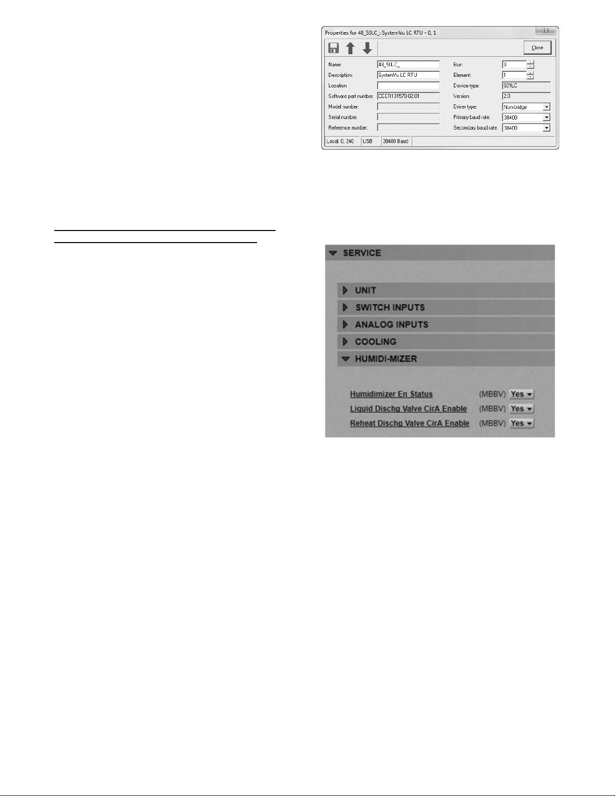
Humidi-- MiZerRSystem Troubleshooting
Use the SystemVut control display or a CCN device to view the
cooling status display and the cooling diagnostic display. See
Optional Humidi--MiZer Dehumidification System starting on
page 19 for information on the cooling operation and the related
Humidi--MiZer system operation. Check the current alarms and
alarm history for any cooling alarm codes and correct any causes
(see Table 13 on page 34). Verify any unique control
configurations per installed site requirements or accessories.
If alarm conditions are corrected and cleared, operation of the
compressors, fans, and Humidi-MiZer system valves may be
verified by using the Service Test mode (see Table 4 on page 11).
In addition to general cooling service analysis (T able 15 on page
37), see Table 16 (on page 39) for general Humidi-MiZer system
service analysis.
NOTE: Wiring, operation, and charge are different on a
Humidi-MiZer system unit compared to a standard unit.
Activating Humidi--MiZer System Operation After
Field Replacement of a SystemVu
Humidi--MiZer system operation is enabled as part of the factory
configuration of the unit. When field replacement of a SystemVu
controller is required, the replacement controller must be
field--configured to control the Humidi--MiZer system option.
Field activation of the Humidi--MiZer system requires use of
Network System Tool Five and either i--Vu
Tools 6.5 (field assistant tool).
NOTE: The i--Vu software or i-- Vu Tools must be version 6.5 or
later. Earlier versions do not support the SystemVu controller.
Connect the computer with the required software to the installed
replacement SystemVu controller. Using Network System Tool
Five, navigate to the Properties screen (see Fig. 22). Enter the
Serial number from the unit nameplate into the Serial number field.
t Controller
R
6.5 software or i--Vu
a48--- 9930
Fig. 22 -- Network System Tools Five Properties Page
Next launch either the i--Vu 6.5 software or the i--Vu Tools 6.5
field assistant and navigate to the Properties page (see Fig. 23). Go
to the Service section and locate HUMIDI--MIZER. Set the
following selections to Yes: Humidimizer En Status, Liquid Dischg
Valve CirA Enable, and Reheat Dischg Valve CirA Enable.
Fig. 23 -- i--Vu Properties Page -- Service Section
a48--- 9940
38
Page 39
PROBLEM CAUSE REMEDY
Subcooling Reheat Mode
Will Not Activate.
Hot Gas Reheat Mode
Will Not Activate.
No Dehumidification Demand.
IOB Operation.
L D V ( 3 --- W a y ) Va l v e O p e r a t i o n .
RDV Valve Operation.
(NOTE: Normally Closed
When De-energized)
Low Sensible Capacity in Normal Cool
or Subcooling Reheat Modes.
Low Suction Pressure and High
Superheat During Normal Cool Mode.
RDV Valve Cycling On/Off.
LEGEND
IOB --- I n p u t --- Ou t p u t B oa r d
LDV --- L i q u i d D i v e r t e r Va l v e
RDV --- Reheat Discharge Valve
RH --- Relative Humidity
Table 16 – Humidi--MiZer System Service Analysis
General cooling mode problem. See Cooling Service Analysis (Table 15).
No dehumidification demand. See No Dehumidification Demand, below.
IOB operation. See IOB Operation, below.
Circuit LDV valve problem. SeeLDVValveOperation,below.
General cooling mode problem. See Cooling Service Analysis (Table 15).
No dehumidification demand. See No Dehumidification Demand, below.
IOB operation. See IOB Operation, below.
Circuit LDV valve problem. SeeLDV(3---Way)ValveOperation,below.
Circuit RDV valve is not open. SeeRDVValveOperation,below.
Outdoor temperature too low.
Relative humidity setpoint is
too low — Humidistat
Relative humidity setpoint is
too low — RH sensor.
Software configuration error
for accessory humidistat.
Software configuration error
for acce ssory humidity sensor.
No humidity signal. Check wiring. Check humidistat or humidity sensor.
Communication loss to Input--- Output Board.
No power to output terminals. Check wiring.
Relay outputs do not change state. Replace faulty IOB.
No 24V signal to input terminals.
Solenoid coil burnout.
Stuck valve. Replace valve. Replace filter drier.
No 24V signal to input terminals.
Solenoid coil burnout.
Stuck valve. Replace valve. Replace filter drier.
RDV valve open or leaking. SeeRDVValveOperation,above.
General cooling mode problem. See Cooling Service Analysis (Table 15).
RDV valve open or leaking. SeeRDVValveOperation,above.
Hot Gas Reheat mode low suction pressure limit.
Check Reheat Circuit Limit Temperatures
Unit ConfigurationsCoolingHumz Lockout OAT
Check/reduce setting on accessory humidistat.
Check Space RH Setpoints (SetpointsSPRH)
Check Space Humidity Switch (SETTINGSUNIT CONFIGURATIONS
SWITCH INPUTS CONFIGSHUMSTAT CHANNEL)
Check RH Sensor (SETTINGSUNIT CONFIGURATIONSANALOG
INPUTS CONFIGSSPRH SENSOR CHANNEL)
Check wiring connections. Alert A099 --- COMM LOSS WITH SIOB
Check using ServiceLIQ DIVERT A TEST
Check IOB relay output.
Check Wiring.
Check transformer and circuit beaker or fuses.
Check continuous over-voltage is less than 10%.
Check under-voltage is less than 15%.
Check for missing coil assembly parts.
Check for damaged valve enclosing tube.
Check using ServiceRDV A TEST
Check IOB relay output.
Check wiring.
Check transformer and circuit breaker or fuses.
Check continuous over-voltage is less than 10%.
Check under-voltage is less than 15%.
Check for missing coil assembly parts.
Check for damaged valve enclosing tube.
Normal Operation During Mixe d Circuit Subcooling and Hot Gas Re heat
Modes at Lower Outdoor Temperatures.
39
Page 40
Economizer Troubleshooting
Use the SystemVut Display to view the economizer status. Check
the current alerts and faults and the alarm history for economizer
specific alerts or any relevant faults or alerts and correct those
issues. Use test mode to troubleshoot by ramping the economizer
up and down with and without the indoor fan and power exhaust
fan on. Inspect the mechanical economizer for actuator, gear, or
blade damage. Ensure the actuator is mounted with the correct
spring return (close damper when no power applied to unit).
Ensure there is a 500 ohm resister across the actuator as the
4--20mA output signal must be converted to 2--10V.
Table 17 – Economizer Service Analysis
PROBLEM POSSIBLE CAUSE REMEDY
Damper Does Not Move. Indoor Fan is off.
Actuator is unplugged at mot or or at
economizer board.
Unit is not configured for economizer. Configure unit for economizer per the
Outdoor-air temperature is above economizer
high temperature lockout.
Outdoor-air temperature is below economizer low
temperature lockout.
Communication loss to economizer board. Check wiring conn ection s.
Damper is jammed. Identify the obstruction and safely remove.
Economizer Operation is Limited
to Minimum Position.
Economizer Position is Less
Than Minimum Position.
Economizer Does Not Return
to Minimum Position.
Damper Does Not Close on
Power Loss.
Economizer is Not at Configured
Minimum Position
LEGEND
CCN --- Carrier Comfort Network
IAQ --- I n d oo r Ai r Qu a l i t y
Minimum position is set incorrectly. Adjust minimum position setting.
Outdoor-air temperature is above economizer
high temperature lockout.
Outdoor-air temperature is below economizer
low temperature lockout.
Enthalpy or differential dry bulb are preventing free
cooling.
Outdoor-air thermistor is faulty. Replace outdoor-air thermistor.
Low suction pressure problem with a compressor. Economizer is operating correctly, identify
IAQ is controlling minimum damper position. Adjust the IAQ settings if incorrect,
Unit is in Unoccupied mode. Adjust unit occupied schedule if incorrect,
Unit is operating under free cooling. Economizer is operating correctly.
Damper is jammed or spring return is backwards. Identify the obstruction and safely remove.
Unit is operating under free cooling or a force is
applied to the commanded position.
R
The Economizer alerts can be summarized as a failure to modulate
the damper blades. This can be due to the actuator not being
properly connected to the damper, or because the actuator’s
feedback signal is indicating that damper is not performing as
commanded. The mechanical disconnect diagnostic will run when
conditions are appropriate to determine proper air temperature
changes. This uses the OAT, RAT, and SAT to tell if the damper is
mixing the outdoor air with the return air. The other alerts inform
where the damper is stuck relative to the commanded position.
Check for proper thermostat connection.
Unit is not configured for continuous fan
operation and the thermostat is not calling for
heating or cooling.
Unit is in Unoccupied mode and there is no
call for heating or cooling.
Tripped circuit breaker.
No power to the unit.
Unit is off via CCN comman d.
Check wiring connections.
instructions.
Adjust the high temperature lockout setting
if it is incorrect, otherwise, economizer is
operating correctly.
Adjust the low temperature lockout setting
if it is incorrect, otherwise, economizer is
operating correctly.
Adjust the high temperature lockout setting
if it is incorrect, otherwise, economizer is
operating correctly.
Adjust the low temperature lockout setting if it is
incorrect, otherwise, economizer is operating
correctly.
Check enthalpy and return air compared to
outside air temperature.
compressor problem.
otherwise, the economizer is operating correctly.
otherwise, economizer is operating correctly.
Economizer is operating correctly.
40
Page 41
Heating Troubleshooting
Use the unit SystemVut Display or a CCN device to view the
heating status display and the heating diagnostic display (see
Appendices) for information on the heating operation. Check the
current alarms and alarm history for any heating alarm codes and
correct any causes. (See Table 13.) Verify any unique control
configurations per installed site requirements or accessories. If
alarms conditions are corrected and cleared, operation of the heat
stages and indoor fan may be verified by using the Service Test
mode. (See Table 4.)
Table 18 – Gas Heating Service Analysis
PROBLEM CAUSE REMEDY
Heat Will Not Turn On. Unit is NOT configured for heat. Check heating configurations using the SystemVu Display
Active alarm. Check active alarms using SystemVu Display and the IGC flash
No power to unit. Check power supply, fuses, wiring, and circuit breakers.
No power to IGC (Integrated Gas Control). Check fuses and plugs.
Heaters off due to time guard to prevent short
Burners Will Not Ignite.
Inadequate Heating.
Poor Flame
Characteristics.
Burners Will Not Turn Off.
cycling.
Thermostat or occupancy schedule set point not
calling for Cooling.
No gas at main burners. Check gas line for air and purge as necessary. After purging gas
Water in gas line. Drain water and in stall drip.
Dirty air filters. Replace air filters.
Gas input too low. Check gas pressure at manifold. Refer to gas valve adjustment.
Thermostat or occupancy schedule set point only
calling for W1.
Unit undersized for load. Decrease load or increase of size of unit.
Restricted airflow. Remove restriction. Check SAT compared to the SAT heating
Too much outdoor air. Check economizer position and configuration. Adjust minimum
Limitswitchcyclesmainburners. Check rotation of blower, thermostat heat anticipator settings,
Incomplete combustion (lack of combustion air)
results in: Aldehyde odors, CO, sooting flame, or
floating flame.
Unit is in Minimum on-time. Check using SystemVu Display and the IGC flash codes.
Unit running in Service Test mode. Check using SystemVu Display.
Main gas valve stuck. Turn off gas supply and unit power. Replace gas valve.
Gas Heat (48LC Units)
See Table 18 for general gas heating service analysis. See Fig. 24
for service analysis of the IGC board logic. Check the status LED
on the IGC board for any flashing alarm codes and correct any
causes. (See Table 19.)
Electric Heat (50LC Units)
See Table 20 for electric heating service analysis.
codes.
Check using SystemVu Display and the IGC flash codes.
Check using SystemVu Display.
line of air , allow gas to dissipate for at least 5 minutes before
attempting to re-light unit.
Allow time for W2 to energize or adjust setpoints.
limits.
position using SystemVu Display.
and temperature rise of unit. Adjust as needed.
Check all screws around flue outlets and burner compartment .
Tighten as necessary.
Cracked heat exchanger, replace.
Unit is over-fired, reduce input. Adjust gas line or manifold
pressure.
Check vent for restriction. Clean as necessary.
Check orifice to burner alignment.
41
Page 42
1 FLASH - INDOOR FAN DELAY
MODIFIED (HEATING)
2 FLASHES - OPENING OF LIMIT
5 FLASHES - IGNITION LOCKOUT
SWITCH
3 FLASHES - FLAME SENSOR
INDICATES FLAME WITH
CLOSED GAS VALVE
4 FLASHES - LIMIT SWITCH
CYCLED 4 TIMES ON SINGLE
CALL FOR HEAT
(No ignition within 15 minutes)
6 FLASHES - INDUCED DRAFT
MOTOR FAULT
(No signal from the Flue Gas
Pressure Switch or 60 seconds)
7 FLASHES - OPENING OF
ROLLOUT SWITCH
8 FLASHES - HARDWARE OR
SOFTWARE FAULT
9 FLASHES - SOFTWARE
LOCKOUT
FLASHING
LED is
ON
CALL FOR
COMBUSTION RELAY ENERGIZES INDUCED DRAFT MOTOR (IDM) THROUGH
IF IDM IS TURNING AT CORRECT SPEED (AT LEAST 2400 RPM), FLUE GAS
PRESSUE SWITCH SENDS CORRECT SIGNAL TO TERMINAL ‘J1’ ON IGC
IF LIMIT SWITCH AND ROLLOUT
SWITCH ARE CLOSED, IGC SAFETY
LOGIC WILL INITIATE IGNITION
OFF
HEATING
‘W1’ FROM BASE CONTROL BOARD ENERGIZES ‘W’
ON IGC - 1 MINUTE LOCK-ON
COMBUSTION RELAY ON IGC IN ENERGIZED
TERMINAL ′CM′ ON IGC
SEQUENCE
24 VOLTS
BETWEEN
F1 AND C
1. BLOWN 5 AMP FUSE
2. DEFECTIVE 24V TRANS.
3. BROKEN WIRE
4. NO POWER TO UNIT
YES
No
DEFECTIVE
IGC BOARD
No
LEGEND
IDM – Induced-Draft Motor
IGC – Integrated Gas Unit Controller
IGC SAFETY LOGIC WILL SHUT
OFF GAS VALVE AND SPARK
20 SECOND PURGE OF HEAT
EXCHANGER
IS THIS THE
33RD RETRY? (OR 15
MINUTES)
Yes
IGNITION LOCKOUT
(5 FLASHES OF LED)
IGC HIGH VOLTAGE
TRANSFORMER CREATES A
10,000 VOLT SPARK FOR 5
SECONDS
No
AFTER 45 SECONDS (OR LESS IF THE TIMING
HAS BEEN REDUCED DUE TO LIMIT SWITCH
TRIPS) IGC WILL ENERGIZE BLOWER RELAY
IDM STOPS, SAFETY LOGIC SHUTS OFF GAS VALVE
IGC SAFETY LOGIC OPENS GAS
DOES IGC DETECT
.2 MICROAMPS FOR 2
SECONDS
Yes
DID LIMIT
SWITCH OPEN BEFORE THE 45
SECONDS (OR THE MODIFIED
TIME) HAS TIMED OUT?
No
NORMAL HEATING OPERATION
HEATING DEMAND SATISFIED
VALVE FOR 5 SECONDS
Yes
SUBTRACT 5 SECONDS FROM
INDOOR FAN ON TIME DELAY
NOTE: Thermostat Fan Switch in the
“AUTO” position.
(DELAY EXTENDED BY 5 SECONDS FOR EACH LIMIT SWITCH TRIP
45 SECOND BLOWER SHUTOFF DELAY
MAXIMUM DELAY: 3 MINUTES)
Fig. 24 -- IGC Service Analysis Logic
42
a48--- 9375
Page 43
Table 19 – IGC Board LED Alarm Codes
LED
FLASH
DESCRIPTION
CODE
On Normal Operation
Off Hardware Failure No gas heating.
1Flash Indoor Fan On/Off Delay
Modified
2Flashes Limit Switch Fault Gas valve and igniter Off.
3Flashes Flame Sense Fault Indoor fan and inducer On. Flame sense normal.
4Flashes Four Consecutive Limit
Switch Fault
5Flashes Ignition Fault No gas heating. Heat call (W) Off.
6Flashes Induced Draft Motor
Fault
7Flashes Rollout Switch Lockout Gas valve and igniter Off.
8Flashes Internal Control Lockout No gas heating. Power reset. IGC has sensed internal hardware or software error. If
9Flashes Temporary Software
LEGEND
IGC - -- Integrated Gas Unit Control
LED --- L i g h t --- E m i t t i n g D i o d e
Lockout
ACTION TAKEN BY
CONTROL
RESET METHOD PROBABLE CAUSE
— — —
—
5 seconds subtracted from
On delay.
5 seconds added to Off
delay (3 min max).
Indoor fan and inducer On.
No gas heating. Heat call (W) Off.
If heat off: no gas heating.
If heat on: gas valve Off
and inducer On.
Indoor fan and inducer On.
No gas heating. 1 hour auto reset, or
Power reset. High temperature limit switch opens during heat
Limit switch closed, or
heat call (W) Off.
Power reset for LED
reset.
Power reset for LED
reset.
Power reset for LED
reset.
Inducer sense normal, or
heat call (W) Off.
Power reset. Rollout switch has opened. Check gas valve
power reset.
NOTES:
1. Ther e is a 3 --- second pause between alarm code displays.
2. If more than one alarm code exists, all applicable alarm codes will be
displayed in numerical sequence.
3. Alarm codes on the IGC will be lost if power to the unit is interrupted.
Loss of power to the IGC. Check 5 amp fuse on IGC,
power to unit, 24V circuit breaker, transformer, and
wiring to the IGC.
exchanger warm-up period before fan-on delay
expires.
High temperature limit switch opens within
10 minutes of heat call (W) Off.
See Limit Switch Fault.
High temperature limit switch is open. Check the
operation of th e indoor (evaporator) fan motor.
Ensure that the supply-air temperature rise is within
the range on the unit nameplate. Check wiring and
limit switch operation.
TheIGCsensedaflamewhenthegasvalveshould
be closed. Check wiring, flame sensor, and gas valve
operation.
4 consecutive limit switch faults within a single call for
heat. See Limit Switch Fault.
Unit unsuccessful ly attempted ignition for 15 minutes.
Check igniter and flame sensor electrode spacing, gaps,
etc. Check flame sense and igniter wiring. Check gas
valve operation and gas supply.
Inducer sense On when heat call Off, or inducer
sense Off when heat call On. Check wiring, voltage,
and operation of IGC motor. Check speed sensor
wiring to IGC.
operation. Check induced-draft blower wheel is
properly secured to motor shaft.
fault is not cleared by resetting 24 v power, replace
the IGC.
Electrical interference is disrupting the IGC software.
PROBLEM CAUSE REMEDY
Heat Will Not Turn On.
Inadequate Heating.
Heat Will Not Turn Off.
Table 20 – Electric Heat Service Analysis
Active alarm. Check active alarms using SystemVu™ Display.
Unit is NOT configured for heat. Check heating configurations using the SystemVu Display
No power to unit. Check power supply, fuses, wiring, and circuit breakers.
Unit is in minimum heat off-time, or minimum cool-heat
changeover time.
Thermostat or occupancy schedule setpoint not
calling for heating.
Heat forced off in Service Test mode. Check usin g SystemVu Display. Turn Service Test mode off.
No 24 VAC at heater contactor.
Open temperature limit switch on heater. Check minimum airflow. Check limit switch when it is cool,
Dirty air filters. Replace air filters.
Thermostat or occupancy schedule setpoint only
calling for W1.
Heat undersized for load. Decrease load or increase size of heater.
Restricted airflow Remove restriction. Check SAT compared to the SAT
Too much outdoor air. Check economizer position and configuration. Adjust
Limit switch cycles heaters. Check rotation of blower and minimum airflow.
Bad heater elements. Power off unit and remove high voltage wires. Check
Unit is in minimum heat on-time. Ch eck using SystemVu Display.
Thermostat or occupancy schedule setpoint still
calling for heating.
Heat forced on in Service Test mode. Check using SystemVu Display. Turn Service Test mode off.
Heater contactor failed. Power off unit. Check contactor and replace if closed.
Check using SystemVu Display.
Check using SystemVu Display.
Check transformer and circuit breaker.
Check auto-reset limit switches on heater.
Check manual-reset limit switch (LS) on indoor fan housing.
replace if open.
Allow time for W2 to energize or adjust setpoints.
heating limits.
minimum position.
resistance of element, replace if open.
Check using SystemVu Display.
43
Page 44
Phase Protection
The phase loss protection option will monitor the three-phase electrical
system to provide phase revers al and phase loss protection.
Phase Reversal Protection
If the control senses an incorrect phase relationship, the relay (K1)
will be de-energized (opening its contact). If the phase relationship
is correct, the relay will be energized. The control has a self-bypass
function after a pre-set time. If the control determines that the three
phases stay in a correct relationship for 10 consecutive minutes, the
relay will stay energized regardless of the phase sequence of three
inputs as long as 24-VAC control voltage is applied. This
self-bypass function will be reset if all three phases are restored in a
phase loss event.
Phase Loss Protection
If the r everse rotat ion boar d sense s any one of the t hree phase inputs
has no AC voltage, the rela y will be de--energized (opening its
contact). This protection i s always active as long as 24-VAC cont rol
voltage is applied, and is not affec ted by the self by- pass f unction of
the phase sequence monitor ing functi on. Howeve r, in the event of
phase loss, t he relay w i ll be r e-energized onl y if all three pha ses a re
restored and the three phases are in the correct sequenc e.
A red LED is provided to indicate the function of the board. See
the table below.
LED STATUS FUNCTION
On Continuously Relay contact closed (normal operation).
Blinking
Off 24---VAC control power not present (off).
Relay contact open (phase loss or phase
reversal has occurred) — No power will be
supplied to the control system.
Thermistor Troubleshooting
The SystemVut controller uses thermistors to sense temperatures
used to control operation of the unit. Resistances at various
temperatures are listed in Table 21. Thermistor pin connection
points are shown in the Major System Components section. The
general locations of the thermistors are shown the Major System
Components section.
Air Temperatures
Air temperatures are measured with 10K thermistors. This includes
supply-air temperature (SAT), outdoor-air temperature (OAT),
space temperature sensors (T55, T56, T59), and return air
temperature (RAT).
The supply air temperature (SAT) and outdoor air temperature
(OAT) thermistors use a snap-mount to attach through the unit
sheet metal panels. The snap-mount tabs must be flattened on the
tip end of the sensor to release for removal from the panel. (See
Fig. 25.) To reinstall, make sure the snap-mount tabs extend out.
Thermistor/Temperature Sensor Check
A digital volt-ohmmeter is required to perform this check.
Connect the digital volt--ohmmeter across the appropriate
thermistor terminals at the J8 connector on the Main Base Board
(see Major System Components section).
Using the voltage reading obtained, read the sensor temperature
from Table 21 (on page 45).
To check thermistor accuracy, measure temperature at
probe location with an accurate thermocouple-type
temperature-measuring instrument. Insulate thermocouple to avoid
ambient temperatures from influencing reading. Temperature
measured by thermocouple and temperature determined from
thermistor voltage reading should be close, within 5F if care was
taken in applying thermocouple and taking readings.
If a more accurate check is required, unit must be shut down and
thermistor removed and checked at a known temperature (freezing
point or boiling point of water) using either voltage drop measured
across thermistor at the J8 connector, or by determining the
resistance with unit shut down and thermistor disconnected from
J8. Compare the values determined with the value read by the
control in the Temperatures mode using the SystemVut display.
Sensor Trim
Corrective offsets can be applied to all the analog inputs. Trim can
be used as a form of calibration. The trim works by adding or
subtracting the specified amount on the specified analog input.
These corrections should only be use when a proper calibrated tool
is used to compare to the sensors reading. These corrections are
only applied to the local sensor values, a building systems (BAS)
communicating values will not account for these corrections. Use
the SERVICE CALIBRATION menu on the SystemVu Displa y to
adjust these values.
Transducer Troubleshooting
The electronic control uses suction and discharge pressure
transducers to measure the pressure of the refrigerant circuits. The
pressure/voltage characteristics of these transducers are in shown in
Table 22 (on page 46) for suction transducers and Table 23 (on
pages 47--48) for discharge transducers. The 5vdc power is applied
to legs A and B of the transducer and legs B to C represent the
signal voltage. To use the voltage drop table for troubleshooting,
read the voltage across A and B, then subtract the voltage reading
from B to C. The voltage drop can be looked up in Table 22 and
Table 23 depending on the type of transducer. The accuracy of
these transducers can be verified by connecting an accurate
pressure gauge to the second refrigerant port in the suction and
discharge lines.
Fig. 25 -- SAT and OAT Thermistor Mounting
C07015
44
Page 45
Table 21 – Temperature (_F) vs Resistance/Voltage Drop Value s for OAT, RAT, SAT, and SPT Thermist ors (10K at 25_C Type II Resistors)
TEMP
(F)
–25 196,453 4.758 59 15,714 3.056 143 2,343 0.949
–24 189,692 4.750 60 15,317 3.025 144 2,297 0.934
–23 183,300 4.741 61 14,925 2.994 145 2,253 0.919
–22 177,000 4.733 62 14,549 2.963 146 2,209 0.905
–21 171,079 4.724 63 14,180 2.932 147 2,166 0.890
–20 165,238 4.715 64 13,824 2.901 148 2,124 0.876
–19 159,717 4.705 65 13,478 2.870 149 2,083 0.862
–18 154,344 4.696 66 13,139 2.839 150 2,043 0.848
–17 149,194 4.686 67 12,814 2.808 151 2,003 0.835
–16 144,250 4.676 68 12,493 2.777 152 1,966 0.821
–15 139,443 4.665 69 12,187 2.746 153 1,928 0.808
–14 134,891 4.655 70 11,884 2.715 154 1,891 0.795
–13 130,402 4.644 71 11,593 2.684 155 1,855 0.782
–12 126,183 4.633 72 11,308 2.653 156 1,820 0.770
–11 122,018 4.621 73 11,031 2.622 157 1,786 0.758
–10 118,076 4.609 74 10,764 2.592 158 1,752 0.745
–9 114,236 4.597 75 10,501 2.561 159 1,719 0.733
–8 110,549 4.585 76 10,249 2.530 160 1,687 0.722
–7 107,006 4.572 77 10,000 2.500 161 1,656 0.710
–6 103,558 4.560 78 9,762 2.470 162 1,625 0.699
–5 100,287 4.546 79 9,526 2.439 163 1,594 0.687
–4 97,060 4.533 80 9,300 2.409 164 1,565 0.676
–3 94,020 4.519 81 9,078 2.379 165 1,536 0.666
–2 91,019 4.505 82 8,862 2.349 166 1,508 0.655
–1 88,171 4.490 83 8,653 2.319 167 1,480 0.645
0 85,396 4.476 84 8,448 2.290 168 1,453 0.634
1 82,729 4.461 85 8,251 2.260 169 1,426 0.624
2 80,162 4.445 86 8,056 2.231 170 1,400 0.614
3 77,662 4.429 87 7,869 2.202 171 1,375 0.604
4 75,286 4.413 88 7,685 2.173 172 1,350 0.595
5 72,940 4.397 89 7,507 2.144 173 1,326 0.585
6 70,727 4.380 90 7,333 2.115 174 1,302 0.576
7 68,542 4.363 91 7,165 2.087 175 1,278 0.567
8 66,465 4.346 92 6,999 2.059 176 1,255 0.558
9 64,439 4.328 93 6,838 2.030 177 1,233 0.549
10 62,491 4.310 94 6,683 2.003 178 1,211 0.540
11 60,612 4.292 95 6,530 1.975 179 1,190 0.532
12 58,781 4.273 96 6,383 1.948 180 1,169 0.523
13 57,039 4.254 97 6,238 1.921 181 1,148 0.515
14 55,319 4.235 98 6,098 1.894 182 1,128 0.507
15 53,693 4.215 99 5,961 1.867 183 1,108 0.499
16 52,086 4.195 100 5,827 1.841 184 1,089 0.491
17 50,557 4.174 101 5,698 1.815 185 1,070 0.483
18 49,065 4.153 102 5,571 1.789 186 1,052 0.476
19 47,627 4.132 103 5,449 1.763 187 1,033 0.468
20 46,240 4.111 104 5,327 1.738 188 1,016 0.461
21 44,888 4.089 105 5,210 1.713 189 998 0.454
22 43,598 4.067 106 5,095 1.688 190 981 0.447
23 42,324 4.044 107 4,984 1.663 191 964 0.440
24 41,118 4.021 108 4,876 1.639 192 947 0.433
25 39,926 3.998 109 4,769 1.615 193 931 0.426
26 38,790 3.975 110 4,666 1.591 194 915 0.419
27 37,681 3.951 111 4,564 1.567 195 900 0.413
28 36,610 3.927 112 4,467 1.544 196 885 0.407
29 35,577 3.903 113 4,370 1.521 197 870 0.400
30 34,569 3.878 114 4,277 1.498 198 855 0.394
31 33,606 3.853 115 4.185 1.475 199 841 0.388
32 32,654 3.828 116 4,096 1.453 200 827 0.382
33 31,752 3.802 117 4,008 1.431 201 814 0.376
34 30,860 3.776 118 3,923 1.409 202 800 0.370
35 30,009 3.750 119 3,840 1.387 203 787 0.365
36 29,177 3.723 120 3,759 1.366 204 774 0.359
37 28,373 3.697 121 3,681 1.345 205 762 0.354
38 27,597 3.670 122 3,603 1.324 206 749 0.349
39 26,838 3.654 123 3,529 1.304 207 737 0.343
40 26,113 3.615 124 3,455 1.284 208 725 0.338
41 25,396 3.587 125 3,383 1.264 209 714 0.333
42 24,715 3.559 126 3,313 1.244 210 702 0.328
43 24,042 3.531 127 3,244 1.225 211 691 0.323
44 23,399 3.503 128 3,178 1.206 212 680 0.318
45 22,770 3.474 129 3,112 1.187 213 670 0.314
46 22,161 3.445 130 3,049 1.168 214 659 0.309
47 21,573 3.416 131 2,986 1.150 215 649 0.305
48 20,998 3.387 132 2,926 1.132 216 639 0.300
49 20,447 3.357 133 2,866 1.114 217 629 0.296
50 19,903 3.328 134 2,809 1.096 218 620 0.292
51 19,386 3.298 135 2,752 1.079 219 610 0.288
52 18,874 3.268 136 2,697 1.062 220 601 0.284
53 18,384 3.238 137 2,643 1.045 221 592 0.279
54 17,904 3.208 138 2,590 1.028 222 583 0.275
55 17,441 3.178 139 2,539 1.012 223 574 0.272
56 16,991 3.147 140 2,488 0.996 224 566 0.268
57 16,552 3.117 141 2,439 0.980 225 557 0.264
58 16,131 3.086 142 2,391 0.965
RESISTANCE
(Ohms)
VOLTAGE
DROP (V)
TEMP
(F)
RESISTANCE
(Ohms)
VOLTAGE
DROP (V)
TEMP
(F)
RESISTANCE
(Ohms)
VOLTAGE
DROP (V)
45
Page 46
Table 22 – Pressure (psig) vs. Voltage Drop Values for Suction Pressure Transducers
PRESSURE
(psig)
0 0.465 68 1.135 136 1.804 204 2.474
2 0.485 70 1.154 138 1.824 206 2.493
4 0.505 72 1.174 140 1.844 208 2.513
6 0.524 74 1.194 142 1.863 210 2.533
8 0.544 76 1.214 144 1.883 212 2.553
10 0.564 78 1.233 146 1.903 214 2.572
12 0.583 80 1.253 148 1.922 216 2.592
14 0.603 82 1.273 150 1.942 218 2.612
16 0.623 84 1.292 152 1.962 220 2.631
18 0.642 86 1.312 154 1.982 222 2.651
20 0.662 88 1.332 156 2.001 224 2.671
22 0.682 90 1.351 158 2.021 226 2.690
24 0.702 92 1.371 160 2.041 228 2.710
26 0.721 94 1.391 162 2.060 230 2.730
28 0.741 96 1.410 164 2.080 232 2.749
30 0.761 98 1.430 166 2.100 234 2.769
32 0.780 100 1.450 168 2.119 236 2.789
34 0.800 102 1.470 170 2.139 238 2.809
36 0.820 104 1.489 172 2.159 240 2.828
38 0.839 106 1.509 174 2.178 242 2.848
40 0.859 108 1.529 176 2.198 244 2.868
42 0.879 110 1.548 178 2.218 246 2.887
44 0.898 112 1.568 180 2.237 248 2.907
46 0.918 114 1.588 182 2.257 250 2.927
48 0.938 116 1.607 184 2.277 252 2.946
50 0.958 118 1.627 186 2.297 254 2.966
52 0.977 120 1.647 188 2.316 256 2.986
54 0.997 122 1.666 190 2.336 258 3.005
56 1.017 124 1.686 192 2.356 260 3.025
58 1.036 126 1.706 194 2.375 262 3.045
60 1.056 128 1.726 196 2.395 264 3.065
62 1.076 130 1.745 198 2.415 266 3.084
64 1.095 132 1.765 200 2.434 268 3.104
66 1.115 134 1.785 202 2.454 270 3.124
VOLTAGE
DROP (V)
PRESSURE
(psig)
VOLTAGE
DROP (V)
PRESSURE
(psig)
VOLTAGE
DROP (V)
PRESSURE
(psig)
VOLTAGE
DROP (V)
46
Page 47
Table 23 – Discharge Pressure Transducer (psig) vs. Voltage
PRESSURE
(psig)
14.5 0.500 95 0.993 176 1.490 257 1.987
16 0.509 96 1.000 177 1.496 258 1.993
17 0.515 97 1.006 178 1.502 259 1.999
18 0.521 98 1.012 179 1.508 260 2.005
19 0.528 99 1.018 180 1.515 261 2.011
20 0.534 100 1.024 181 1.521 262 2.017
21 0.540 101 1.030 182 1.527 263 2.023
22 0.546 102 1.036 183 1.533 264 2.029
23 0.552 103 1.043 184 1.539 265 2.036
24 0.558 104 1.049 185 1.545 266 2.042
25 0.564 105 1.055 186 1.551 267 2.048
26 0.570 106 1.061 187 1.557 268 2.054
27 0.577 107 1.067 188 1.564 269 2.060
28 0.583 108 1.073 189 1.570 270 2.066
29 0.589 109 1.079 190 1.576 271 2.072
30 0.595 110 1.085 191 1.582 272 2.079
31 0.601 111 1.092 192 1.588 273 2.085
32 0.607 112 1.098 193 1.594 274 2.091
33 0.613 113 1.104 194 1.600 275 2.097
34 0.620 114 1.110 195 1.606 276 2.103
35 0.626 115 1.116 196 1.613 277 2.109
35 0.626 116 1.122 197 1.619 278 2.115
36 0.632 117 1.128 198 1.625 279 2.121
37 0.638 118 1.134 199 1.631 280 2.128
38 0.644 119 1.141 200 1.637 281 2.134
39 0.650 120 1.147 201 1.643 282 2.140
40 0.656 121 1.153 202 1.649 283 2.146
41 0.662 122 1.159 203 1.656 284 2.152
42 0.669 123 1.165 204 1.662 285 2.158
43 0.675 124 1.171 205 1.668 286 2.164
44 0.681 125 1.177 206 1.674 287 2.170
45 0.687 126 1.184 207 1.680 288 2.177
46 0.693 127 1.190 208 1.686 289 2.183
47 0.699 128 1.196 209 1.692 290 2.189
48 0.705 129 1.202 210 1.698 291 2.195
49 0.711 130 1.208 211 1.705 292 2.201
50 0.718 131 1.214 212 1.711 293 2.207
51 0.724 132 1.220 213 1.717 294 2.213
52 0.730 133 1.226 214 1.723 295 2.220
53 0.736 134 1.233 215 1.729 296 2.226
54 0.742 135 1.239 216 1.735 297 2.232
55 0.748 136 1.245 217 1.741 298 2.238
56 0.754 137 1.251 218 1.747 299 2.244
57 0.761 138 1.257 219 1.754 300 2.250
58 0.767 139 1.263 220 1.760 301 2.256
59 0.773 140 1.269 221 1.766 302 2.262
60 0.779 141 1.275 222 1.772 303 2.269
61 0.785 142 1.282 223 1.778 304 2.275
62 0.791 143 1.288 224 1.784 305 2.281
63 0.797 144 1.294 225 1.790 306 2.287
64 0.803 145 1.300 226 1.797 307 2.293
65 0.810 146 1.306 227 1.803 308 2.299
66 0.816 147 1.312 228 1.809 309 2.305
67 0.822 148 1.318 229 1.815 310 2.311
68 0.828 149 1.325 230 1.821 311 2.318
69 0.834 150 1.331 231 1.827 312 2.324
70 0.840 151 1.337 232 1.833 313 2.330
71 0.846 152 1.343 233 1.839 314 2.336
72 0.852 153 1.349 234 1.846 315 2.342
73 0.859 154 1.355 235 1.852 316 2.348
74 0.865 155 1.361 236 1.858 317 2.354
75 0.871 156 1.367 237 1.864 318 2.361
76 0.877 157 1.374 238 1.870 319 2.367
77 0.883 158 1.380 239 1.876 320 2.373
78 0.889 159 1.386 240 1.882 321 2.379
79 0.895 160 1.392 241 1.888 322 2.385
80 0.902 161 1.398 242 1.895 323 2.391
81 0.908 162 1.404 243 1.901 324 2.397
82 0.914 163 1.410 244 1.907 325 2.403
83 0.920 164 1.416 245 1.913 326 2.410
84 0.926 165 1.423 246 1.919 327 2.416
85 0.932 166 1.429 247 1.925 328 2.422
86 0.938 167 1.435 248 1.931 329 2.428
87 0.944 168 1.441 249 1.938 330 2.434
88 0.951 169 1.447 250 1.944 331 2.440
89 0.957 170 1.453 251 1.950 332 2.446
90 0.963 171 1.459 252 1.956 333 2.452
91 0.969 172 1.466 253 1.962 334 2.459
92 0.975 173 1.472 254 1.968 335 2.465
93 0.981 174 1.478 255 1.974 336 2.471
94 0.987 175 1.484 256 1.980 337 2.477
VOLTAGE
DROP (V)
PRESSURE
(psig)
VOLTAGE
DROP (V)
PRESSURE
(psig)
VOLTAGE
DROP (V)
PRESSURE
(psig)
VOLTAGE
DROP (V)
47
Page 48
Table 23 -- Discharge Pressure Transducer (psig) vs. Voltage (cont)
PRESSURE
(psig)
338 2.483 421 2.992 504 3.501 587 4.010
339 2.489 422 2.998 505 3.507 588 4.016
340 2.495 423 3.004 506 3.513 589 4.022
341 2.502 424 3.010 507 3.519 590 4.028
342 2.508 425 3.016 508 3.525 591 4.034
343 2.514 426 3.023 509 3.531 592 4.040
344 2.520 427 3.029 510 3.538 593 4.046
345 2.526 428 3.035 511 3.544 594 4.052
346 2.532 429 3.041 512 3.550 595 4.059
347 2.538 430 3.047 513 3.556 596 4.065
348 2.544 431 3.053 514 3.562 597 4.071
349 2.551 432 3.059 515 3.568 598 4.077
350 2.557 433 3.066 516 3.574 599 4.083
351 2.563 434 3.072 517 3.580 600 4.089
352 2.569 435 3.078 518 3.587 601 4.095
353 2.575 436 3.084 519 3.593 602 4.102
354 2.581 437 3.090 520 3.599 603 4.108
355 2.587 438 3.096 521 3.605 604 4.114
356 2.593 439 3.102 522 3.611 605 4.120
357 2.600 440 3.108 523 3.617 606 4.126
358 2.606 441 3.115 524 3.623 607 4.132
359 2.612 442 3.121 525 3.629 608 4.138
360 2.618 443 3.127 526 3.636 609 4.144
361 2.624 444 3.133 527 3.642 610 4.151
362 2.630 445 3.139 528 3.648 611 4.157
363 2.636 446 3.145 529 3.654 612 4.163
364 2.643 447 3.151 530 3.660 613 4.169
365 2.649 448 3.157 531 3.666 614 4.175
366 2.655 449 3.164 532 3.672 615 4.181
367 2.661 450 3.170 533 3.679 616 4.187
368 2.667 451 3.176 534 3.685 617 4.193
369 2.673 452 3.182 535 3.691 618 4.200
370 2.679 453 3.188 536 3.697 619 4.206
371 2.685 454 3.194 537 3.703 620 4.212
372 2.692 455 3.200 538 3.709 621 4.218
373 2.698 456 3.206 539 3.715 622 4.224
374 2.704 457 3.213 540 3.721 623 4.230
375 2.710 458 3.219 541 3.728 624 4.236
376 2.716 459 3.225 542 3.734 625 4.243
377 2.722 460 3.231 543 3.740 626 4.249
378 2.728 461 3.237 544 3.746 627 4.255
379 2.734 462 3.243 545 3.752 628 4.261
380 2.741 463 3.249 546 3.758 629 4.267
381 2.747 464 3.256 547 3.764 630 4.273
382 2.753 465 3.262 548 3.770 631 4.279
383 2.759 466 3.268 549 3.777 632 4.285
384 2.765 467 3.274 550 3.783 633 4.292
385 2.771 468 3.280 551 3.789 634 4.298
386 2.777 469 3.286 552 3.795 635 4.304
387 2.784 470 3.292 553 3.801 636 4.310
388 2.790 471 3.298 554 3.807 637 4.316
389 2.796 472 3.305 555 3.813 638 4.322
390 2.802 473 3.311 556 3.820 639 4.328
391 2.808 474 3.317 557 3.826 640 4.334
392 2.814 475 3.323 558 3.832 641 4.341
393 2.820 476 3.329 559 3.838 642 4.347
394 2.826 477 3.335 560 3.844 643 4.353
395 2.833 478 3.341 561 3.850 644 4.359
396 2.839 479 3.347 562 3.856 645 4.365
397 2.845 480 3.354 563 3.862 646 4.371
398 2.851 481 3.360 564 3.869 647 4.377
399 2.857 482 3.366 565 3.875 648 4.384
400 2.863 483 3.372 566 3.881 649 4.390
401 2.869 484 3.378 567 3.887 650 4.396
402 2.875 485 3.384 568 3.893 651 4.402
403 2.882 486 3.390 569 3.899 652 4.408
404 2.888 487 3.397 570 3.905 653 4.414
405 2.894 488 3.403 571 3.911 654 4.420
406 2.900 489 3.409 572 3.918 655 4.426
407 2.906 490 3.415 573 3.924 656 4.433
408 2.912 491 3.421 574 3.930 657 4.439
409 2.918 492 3.427 575 3.936 658 4.445
410 2.925 493 3.433 576 3.942 659 4.451
411 2.931 494 3.439 577 3.948 660 4.457
412 2.937 495 3.446 578 3.954 661 4.463
413 2.943 496 3.452 579 3.961 662 4.469
414 2.949 497 3.458 580 3.967 663 4.475
415 2.955 498 3.464 581 3.973 664 4.482
416 2.961 499 3.470 582 3.979 665 4.488
417 2.967 500 3.476 583 3.985 666 4.494
418 2.974 501 3.482 584 3.991 667 4.500
419 2.980 502 3.488 585 3.997
420 2.986 503 3.495 586 4.003
VOLTAGE
DROP (V)
PRESSURE
(psig)
VOLTAGE
DROP (V)
PRESSURE
(psig)
VOLTAGE
DROP (V)
PRESSURE
(psig)
VOLTAGE
DROP (V)
48
Page 49
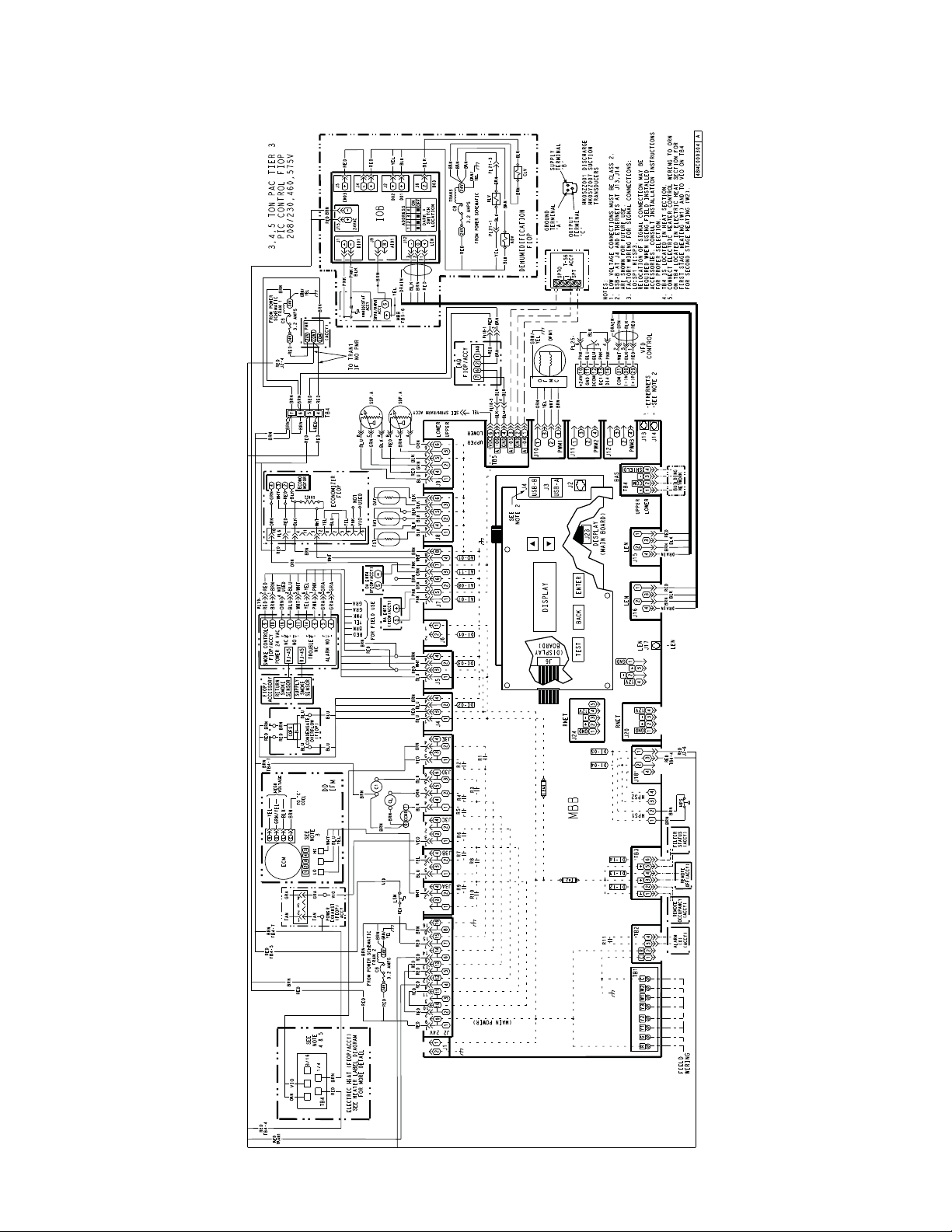
MAJOR SYSTEM COMPONENTS
General
The 48/50LC single package rooftop units are avail a ble with the
factory--install ed optional SystemV ut electronic c ont rol sys tem that
monitors all operations of the rooftop. The control system is
compose d of sever al main control components and avai lable
factory-installed options or field-installed accessories as listed in
sections below. See Fig. 26 -- 31 for examples of typical control and
power schematics for 48/50LC units.
Fig. 26 -- 50LC 04--06 SystemVut Control Schematic
49
a48--- 9941
Page 50
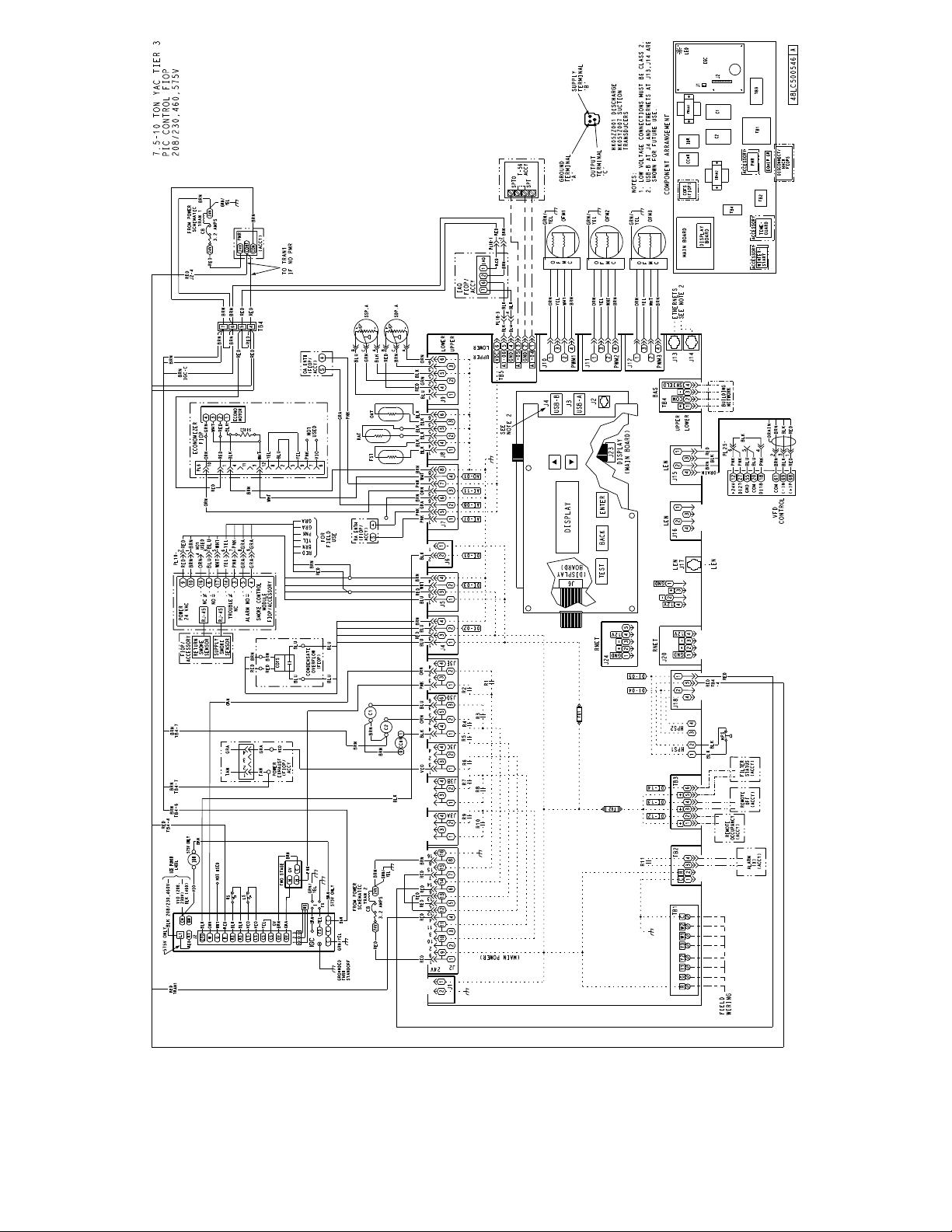
Fig. 27 -- 48LC 08--12 SystemVut Control Schematic
50
C14329B
Page 51
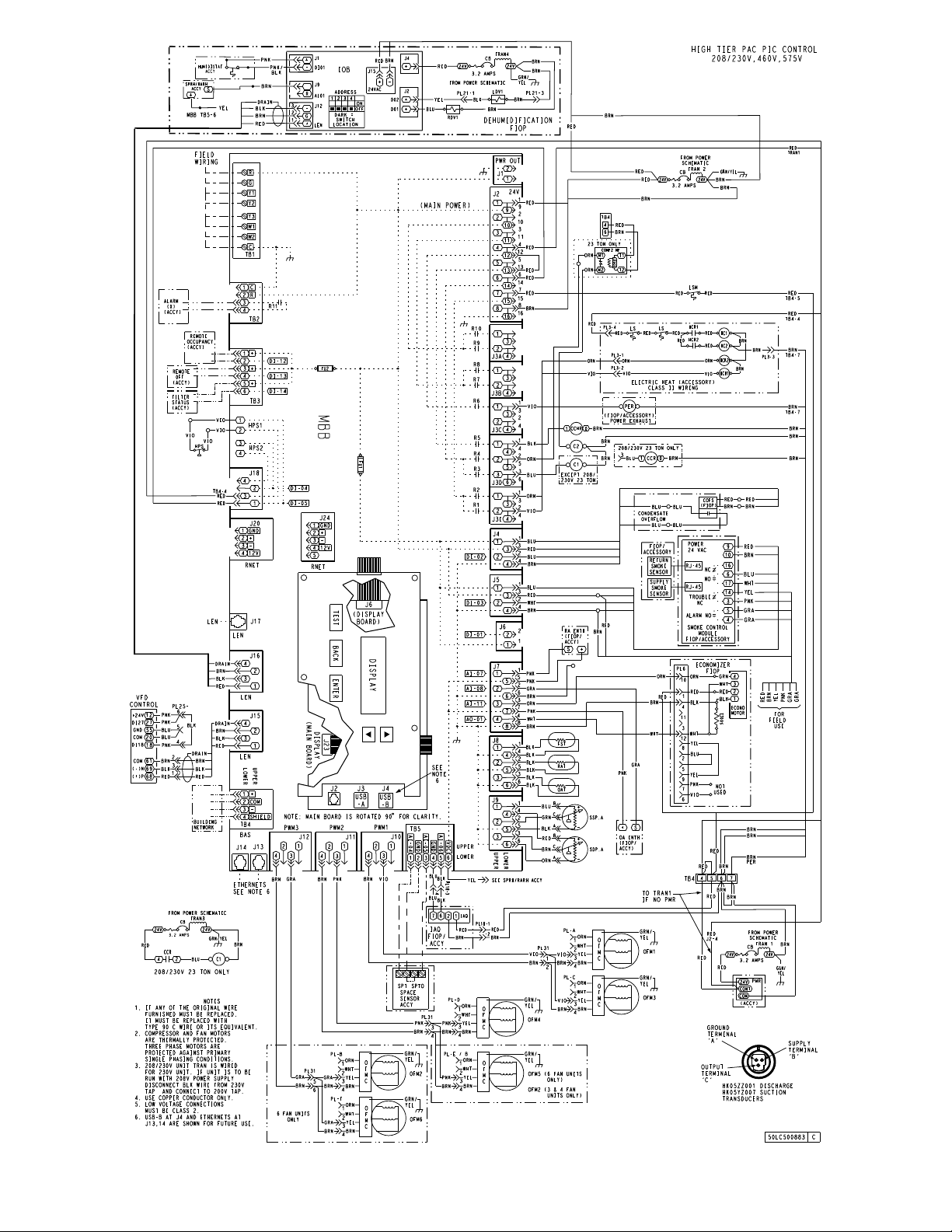
Fig. 28 -- 50LC 14--26 SystemVut Control Schematic
51
a50--- 9603
Page 52
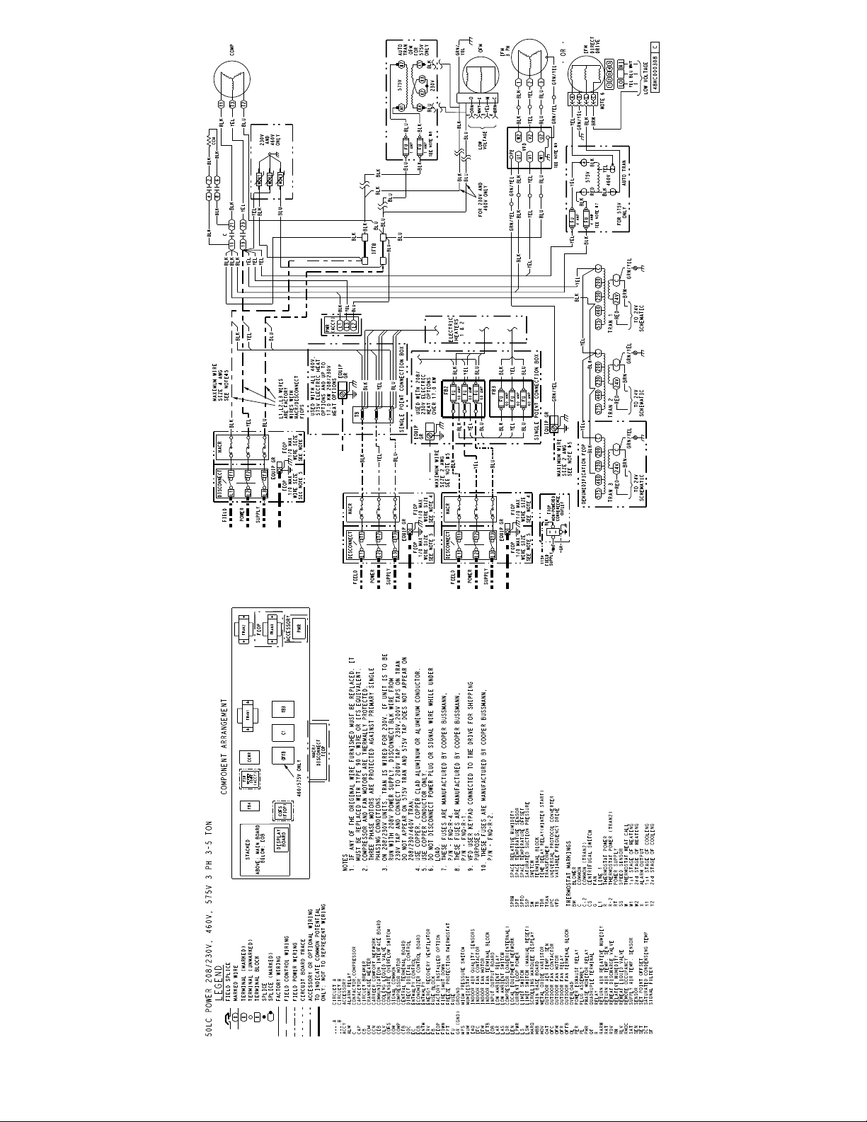
Fig. 29 -- 50LC 04--06 SystemVut Power Schematic
52
a48--- 9942
Page 53
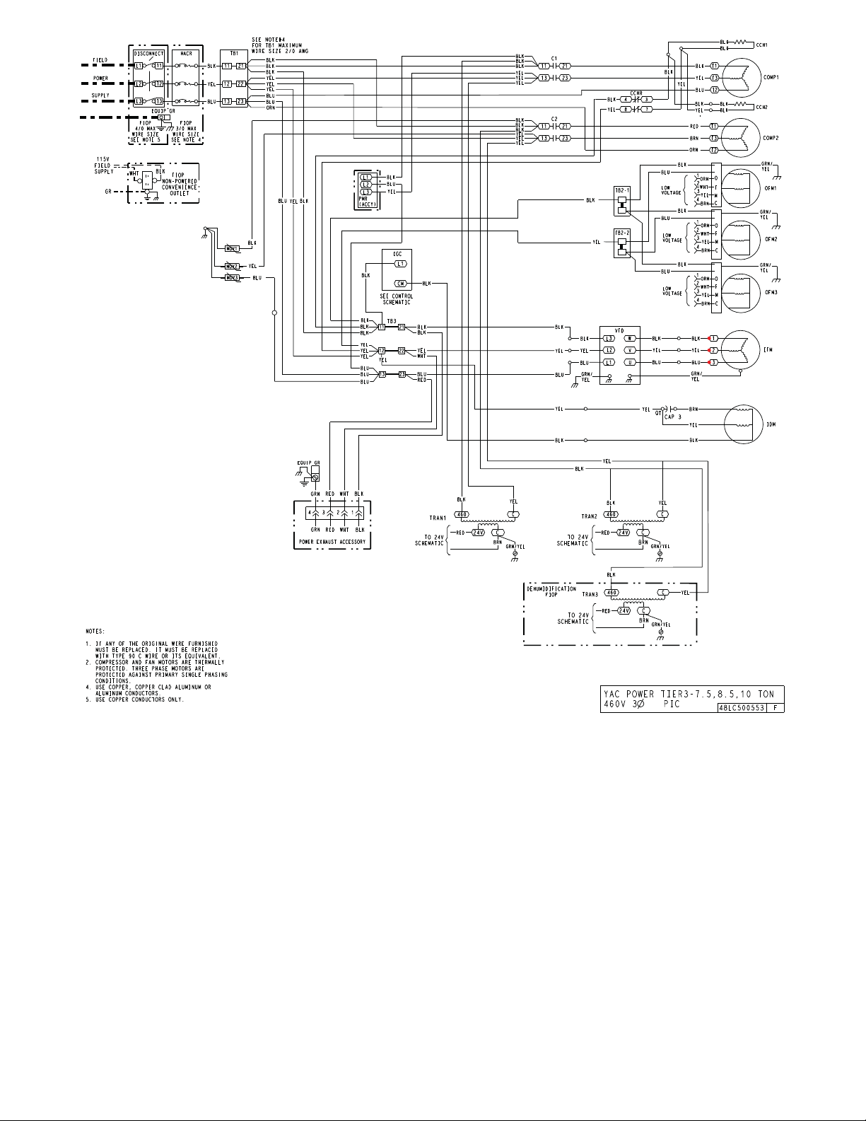
Fig. 30 -- 48LC 08--12 SystemVut Power Schematic
53
a48--- 9943
Page 54
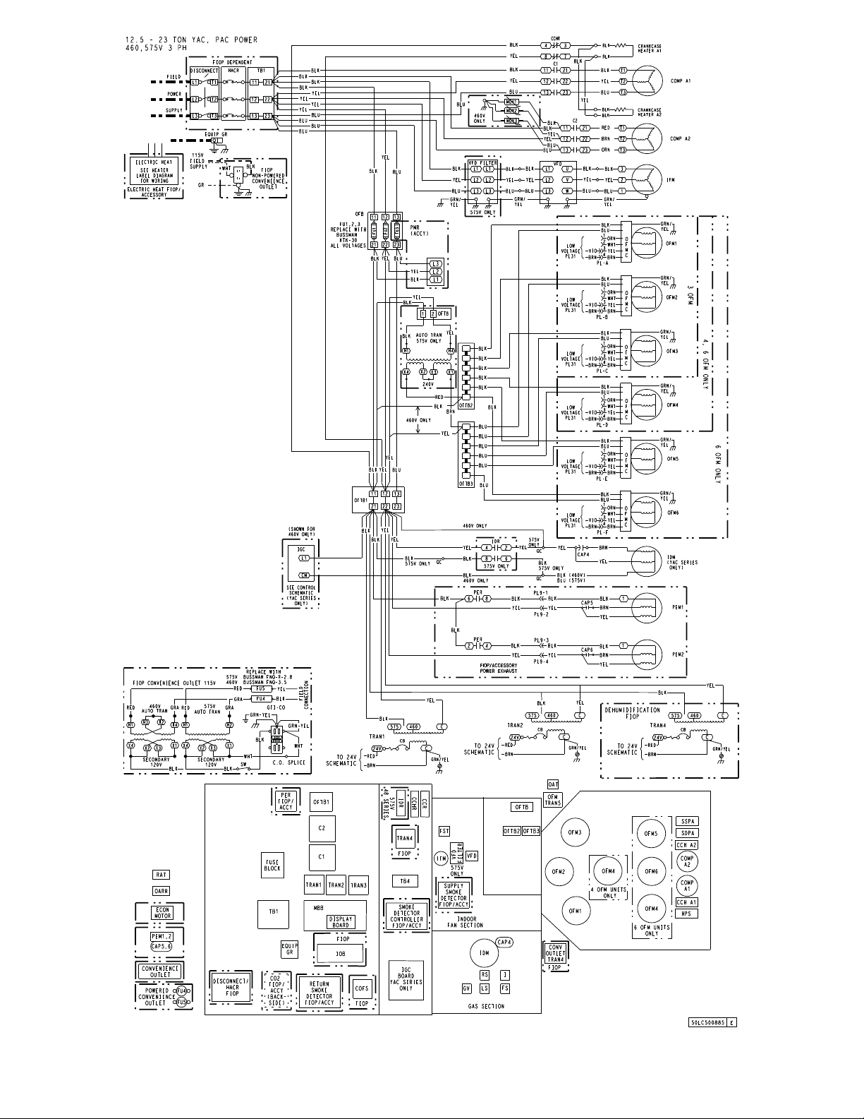
Fig. 31 -- 48/50LC 14--26 SystemVut Power Schematic
54
a48--- 9944
Page 55
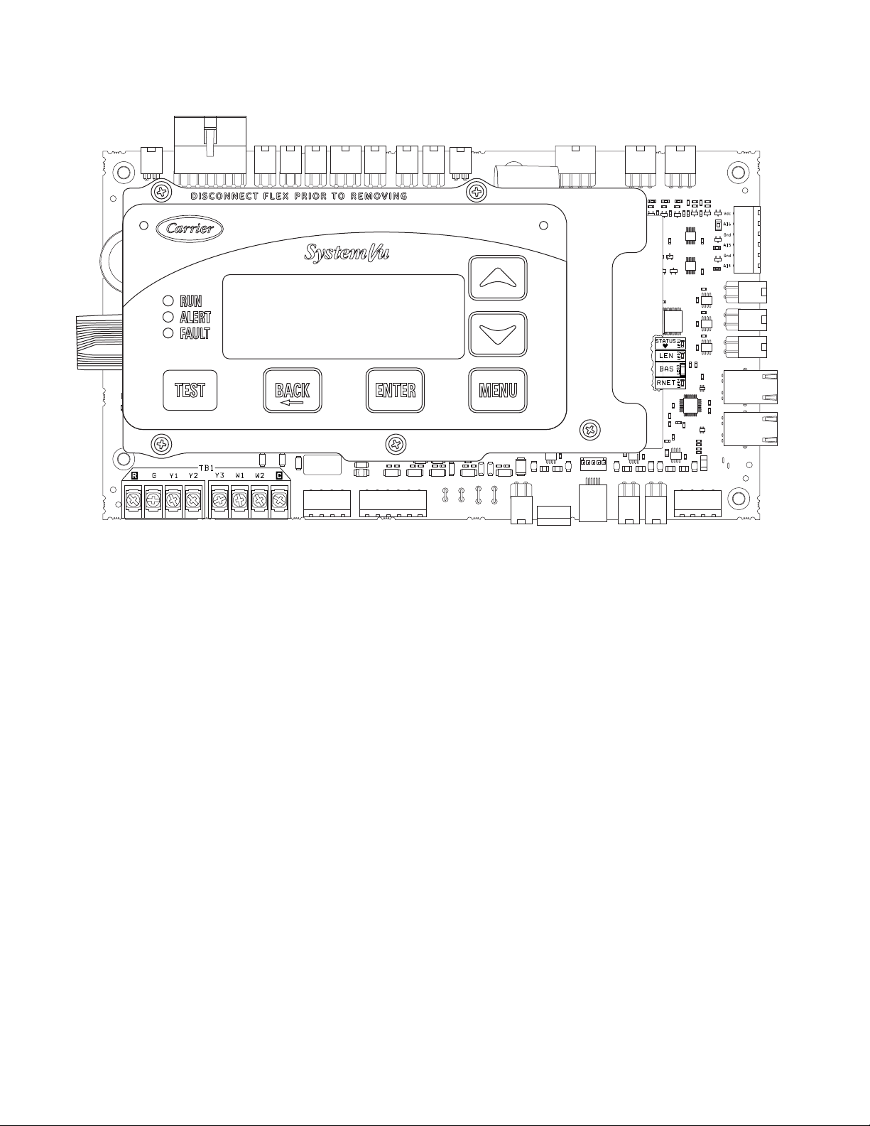
Main Base Board (MBB)
See Fig. 32 and Table 24. The majority of the I/O is connected to
the MBB which executes the controls operation of the unit from
the software that is loaded onto it.
J2
J1
J3A J3B J3C J3D J3E J4 J5 J6 J7
J8 J9
TB5
J10
J11
J12
J13
J14
TB4J15J16J17J20J18TB3TB2TB1
C150161
Fig. 32 -- Main Base Board (MBB)
55
Page 56
Table 24 – Main Base Board (MBB) Connections
DISPLAY NAME SENSOR LOCATION I/O TYPE POINT NAME
INPUTS
Input power from TRAN2 Control Box 24 VAC J2, 1 & 8
COFS Dain Pan 24 VAC COFS J 4 , 1 --- 4
FIRE SHUTDOWN Supply/Return/Space Switch input FIREDOWN J 5 , 1 --- 4
IGC FAN REQUEST Gas section Switch input IGC_IFO J 6 , 1 --- 2
RARH LEVEL Return/Space 0 --- 2 0 mA RARH J7,1,5---6
OARH LEVEL Economizer 0 --- 2 0 m A OARH J7,2,6---7
ECON ACT POSITION Economizer 2 --- 1 0 v d c DAMPPOS J7,3,8
FAN SUPPLY TEMP Indoor fan housing 10k thermistor FST J8,1,4
RETURN AIR TEMP Return 10k thermistor RAT J8,2,5
OUTDOOR AIR TEMP Outdoor coil 10k thermistor OAT J8,3,6
CIR.A SUC. PRESS Circuit A Suction pipe 0 --- 5 VDC pressure transducer SSP_A J 9 , 1 --- 2 , 5
CIR.A DIS. PRESS Circuit A Discharge pipe 0 --- 5 VDC pressure transducer SDP_A J 9 , 4 --- 3 , 6
IAQ LEVEL Return/Space 0 --- 2 0 m A IAQ T B 5 , 4 --- 6
SLIDER OFFSET VAL Space 10k thermistor SPTO T B 5 , 2 --- 3
SPACE TEMPERATURE Space 10k t hermistor SPACE_T T B 5 , 1 --- 2
CIR.A HPS Circuit A Discharge pipe Switch Input CIRA_HPS QC, 1--- 2J 18, 1, 3
Configurable F i e l d --- i n s t a l l e d Switch Input QC, 3--- 4J18, 2,4
REMOTE OCC SWITCH F i e l d --- i n s t a l l e d Switch Input REMOCC T B 3 , 1 --- 2
REMOTE SHUTDOWN F i e l d --- i n s t a l l e d Sw itch Input REMSHUT T B 3 , 3 --- 4
FILTER STATUS SW Indoor fan section Switch Input FILTSTAT T B 3 , 5 --- 6
TSTAT G INPUT Spa ce Switch Input G TB1, G
TSTAT Y1 INPUT Space Switch Input Y1 TB1, Y1
TSTAT Y2 INPUT Space Switch Input Y2 TB1, Y2
TSTAT Y3 INPUT Space Switch Input Y3 TB1, Y3
TSTAT W1 INPUT Space Switch Input W1 TB1, W1
TSTAT W2 INPUT Space Switch Input W2 TB1, W2
OUTPUTS
Optional power out Not Used 24 VAC J1 , 1 --- 2
ECON CMD POSITION 0 --- 2 0 mA DAMPCMD J7,4,8
ODF SPEED OUT 1 PWM1 ODF1SPD J10, 1 --- 4
ODF SPEED OUT 2 PWM2 ODF2SPD J11, 1 --- 4
ODF SPEED OUT 3 PWM3 ODF3SPD J12, 1 --- 4
ALARM RELAY Relay ALMOUT T B 2 , 3 --- 4
not used Not Used Relay J3A, 1, 3
not used Not Used Relay J3A, 2, 4
not used Not Used Relay J3B, 1, 3
not used Not Used Relay J3B, 2, 4
PE1 RELAY Relay PE1 J 3 C , 1 --- 4
CCH RELAY Relay CCHR1 J3D, 1, 4
COMPRESSOR A2 Relay COMP_A2 J3D, 2, 5
COMPRESSOR A1 Relay COMP_A1 J3D, 3, 6
HEAT 2 RELAY Relay HEAT_2 J3E, 1, 3
HEAT 1 RELAY Relay HEAT_1 J3E, 2, 4
COMMUNICATION
Building Automated System (BAS) Building Communication T B 4 , 1 --- 5
Ethernet Not Used Communication J13, J14
IDF SPEED OUTPUT Indoor fan section Communication FANSPEED J15, 1--- 4
Expansion LEN Bus Not Used Communication J16, 1 ---4
Local Equipment Ne twork (LEN) Communication J17
RNET Sensors Building Communication J20, 1 --- 4
Display Copper Cable Communication J23
RNET Service Access Communication J24, 1 --- 5
DISPLAY CONNECTIONS
Display Copper Cable Communication J1
Local Equipment Ne twork (LEN) Communication J2
U S B --- A Communication J3
U S B --- B Not Used Communicat ion J4
Keypad Ribbon Cable Communication J6
CONNECTION PIN
NUMBER
56
Page 57
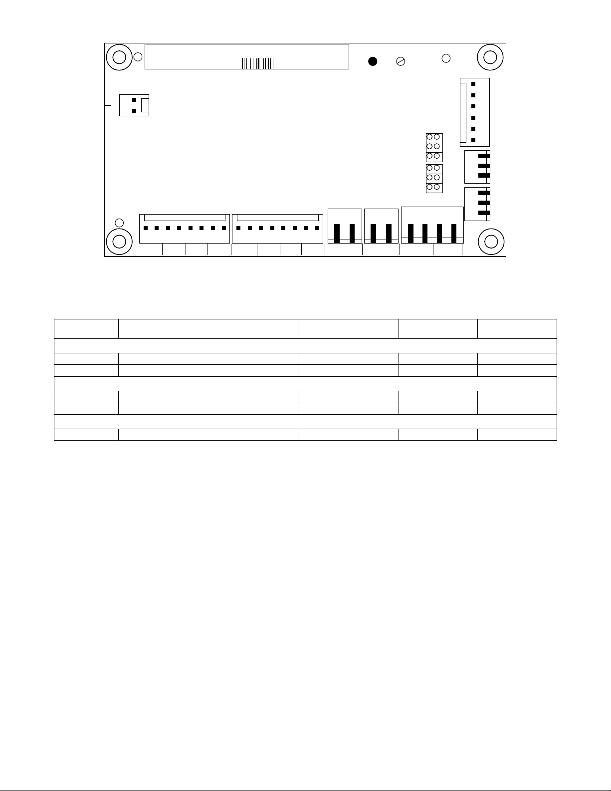
Input-- Output Board (IOB)
PD4-AUX1 32GB 500 322 EE CEPL130487-01
J1
24VAC
12 11
STATUS SIO
CH14
J9
1
SIO
T
P
V
J8
32
1
2
3
-- GRSV RSV +--G +
T
P
V
CH13
CH13 CH14
J3
J5J4
J2
J7
CH
1
CH
CH
CH
CH
CH
--
--
--
--
2
3
4
--
5
CH
--
6
--
7
CH
8
CH
--
9
CH
--
10
CH
--
--
11
Fig. 33 -- Input--Output Board (IOB)
Table 25 – Input--Output Board (IOB) Connections
DISPLAY NAME POINT DESCRIPTION SENSOR LOCATION TYPE OF I/O
INPUTS
HUM HUMIDISTAT F i e l d --- i n s t a l l e d Switch Input J1.1
SPRH SPACE RELATIVE HUMIDITY F i e l d --- i n s t a l l e d 0 --- 2 0 m A J9.2
OUTPUTS
RDV REHEAT DISCHARGE VALVE 24 VAC J2, 1
LDV LIQUID DISCH ARGE VALVE 24 VAC J2, 2
COMMUNICATION
LEN LOCAL EQUIPMENT NETWORK (LEN) Communication J12
CH
12
J6
--
CONNECTION
PIN NUMBER
a50--- 9608
57
Page 58
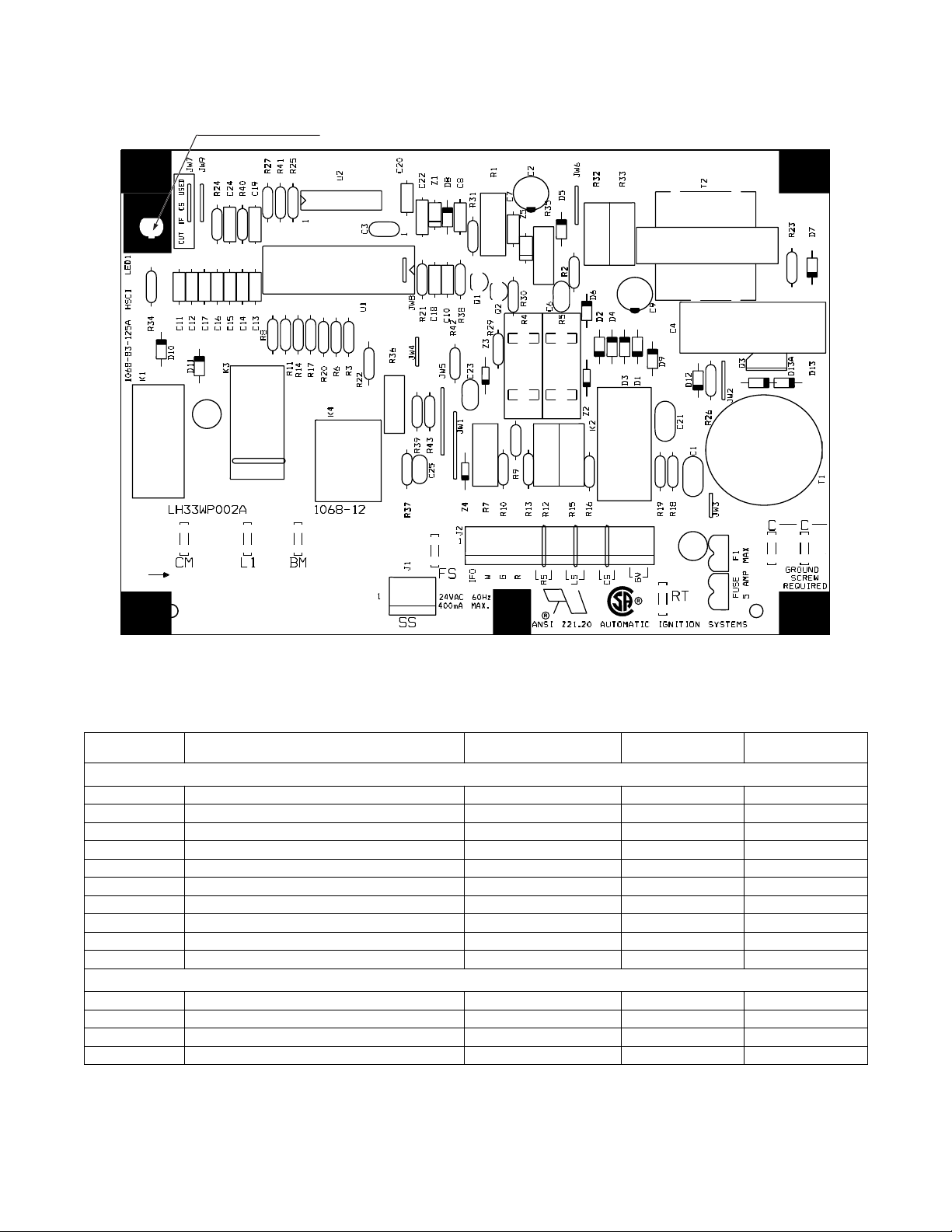
Integrated Gas Control (IGC) Board
The IGC is provided on gas heat units. The IGC controls the direct
spark ignition system and monitors the rollout switch, limit switch,
and flue gas pressure switch.
RED LED-STATUS
Fig. 34 -- Integrated Gas Control (IGC) Board
Table 26 – Integrated Gas Control (IGC) Board Connections
TERMINAL
LABEL
RT, C Power for IDR on 575v units control box 24 VAC Spade
C Input power common Spade
SS Speed sensor gas section analog input J 1 , 1 --- 3
FS, T1 Flame sensor gas section switch input Spade
W Heat stage 1 Call MBB to IGC 24 VAC J2, 2
G Indoor Fan Call not used 24 VAC J2, 3
R Input power from TRAN 1 TB4 to IGC 24 VAC J2, 4
RS Rollout switch gas section switch input J 2 , 5 --- 6
LS Limit switch gas section switch input J 2 , 7 --- 8
CS Centrifuga l switch (not used) switch input J 2 , 9 --- 1 0
L1, CM Induced draft combustion motor or relay gas section line VAC
IFO Indoor fan request IGC to MBB relay J2, 1
GV (W1) Gas valve (heat stage 1) gas section relay J2, 12
GV (W2) Gas Valve (heat stage 2, from CTB) gas section Not on IGC
POINT DE SCRIPTION SENSOR LOCATION TYPE OF I/O
INPUTS
OUTPUTS
CONNECTION
PIN NUMBER
C07028
58
Page 59
Protective Devices
Compressor Protection
Overcurrent
Each compressor has internal line break motor protection.
Overtemperature
Each compressor has an internal protector to protect it against
excessively high discharge gas temperatures.
High--Pressure Switch
If the high-pressure switch trips, the compressor will shut down
and the Circuit A High Pressure Alert will activate. Refer to the
alarm section for the High pressure alert.
Evaporator Fan Motor Protection
In the belt drive application, the VFD serves as the motor thermal
and over-current protection. Refer to Major Component’s section
for more detail on the VFD.
!
EQUIPMENT DAMAGE HAZARD
Failure to follow this caution may result in damage to the unit.
DO not bypass the VFD while running the motor. Do not
change VFD parameter associated with motor characteristics,
theseare factoryprogrammed for motor protection. Damage to
the motor or the VFD can occur.
Condenser--Fan Motor Protection
The ECM motor is protected from locked rotor and over-current
protection through the electronic control module attached to the
motor.
Saturated Suction Pressure (SSP)
If the SSP f or a particular circuit is re ading below the alarm set point
for an extended period of time, that circuit will be shut down. After 15
minutes, the alarm will automatically reset. If this alarm occurs 3 times
consecutively, the circuit will remain locked out until an alarm reset is
initiated via CCN or manually via the SystemVut controller display
(see Alarms and Alerts section for more details).
CAUTION
Condensate Overflow Switch (COFS)
A separate factory installed device can detect a full drain pan. This
device consists of a pan sensor to detect the water level and a relay
control switch to read the sensor. The control switch is located in
the unit control box and feeds into the SystemVu control to trip a
condensate overflow fault. The relay switch is a normally open
device that closes when power is applied. If the sensor detects high
water levels for 10 seconds straight, it will open the contact
removing the input provided to the SystemVu control. The switch
will also turn its red LED on. If the water level is low enough for 5
minutes the relay will close again applying the input back to the
SystemVu controller. A blinking red LED on the switch indicates
that the sensor has been disconnected.
Space Mounted Sensors
Space Temperature Sensor (T--55)
The T-55 space temperature sensor (part no. 33ZCT55SPT) is a
field-installed accessory. The sensor is installed on a building
interior wall to measure room air temperature. The T-55 sensor also
includes an override button on the front cover to permit occupants
to override the Unoccupied Schedule (if programmed).
TB5--1 Sensor Input.............
TB5--2 Sensor Common.............
Space Temperature Sensor (T--56)
The T-56 space temperature sensor (part no. 33ZCT56SPT) is a
field-installed accessory . This sensor includes a sliding scale on the
front cover that permits an occupant to adjust the space temperature
set point remotely. The T-56 sensor also includes an override
button on the front cover to allow occupants to override the
unoccupied schedule (if programmed).
TB5--1 Sensor Input...........
TB5--2 Sensor Common...........
TB5--3 Setpoint Offset Input...........
Space Temperature Sensor Averaging
See Fig. 35 for space temperature averaging with T-55 sensors
only. If the use of one T-56 sensor is required, refer to Fig. 36.
59
Page 60
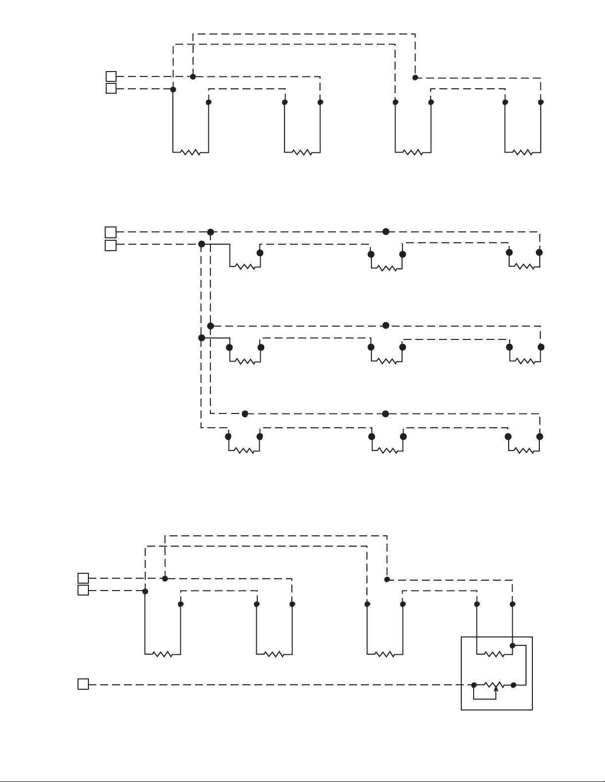
RED
T
BLK
RED
BLK
TB1-T55
1
2
TO MAIN
BASE BOARD
TB1-T55
1
2
TO MAIN
BASE BOARD
RED
BLK
LEGEND
B -- Terminal Block
______ -- Factory Wiring
_ _ _ _ -- Field Wiring
RED
BLK
SENSOR 1 SENSOR 2 SENSOR 3 SENSOR 4
RED
BLK
SPACE TEMPERATURE AVERAGING --4 T-55 SENSOR APPLICATION
RED
BLK
BLK
SENSOR 1
RED
RED
BLK
SENSOR 2
RED
BLK
RED
BLK
RED
BLK
SENSOR 3
SENSOR 6SENSOR 5
BLK
SENSOR 4
RED
RED
BLK
RED
BLK
SENSOR 8SENSOR 7 SENSOR 9
SPACE TEMPERATURE AVERAGING --9 T-55 SENSOR APPLICATION
C07032
Fig. 35 -- Space Temperature Sensor Averaging
RED
BLK
TB1-T55
1
2
TO MAIN
BASE
BOARD
RED
BLK
RED
BLK
RED
BLK
RED
BLK
TB1-T55
3
TO MAIN
BASE
BOARD
T-55 SENSOR 1 T-55 SENSOR 2 T-55 SENSOR 3 T-56 SENSOR 4
WHT
C07033
Fig. 36 -- Space Temperature Sensor Averaging with 3 T--55 Sensors and One T--56 Sensor
60
Page 61
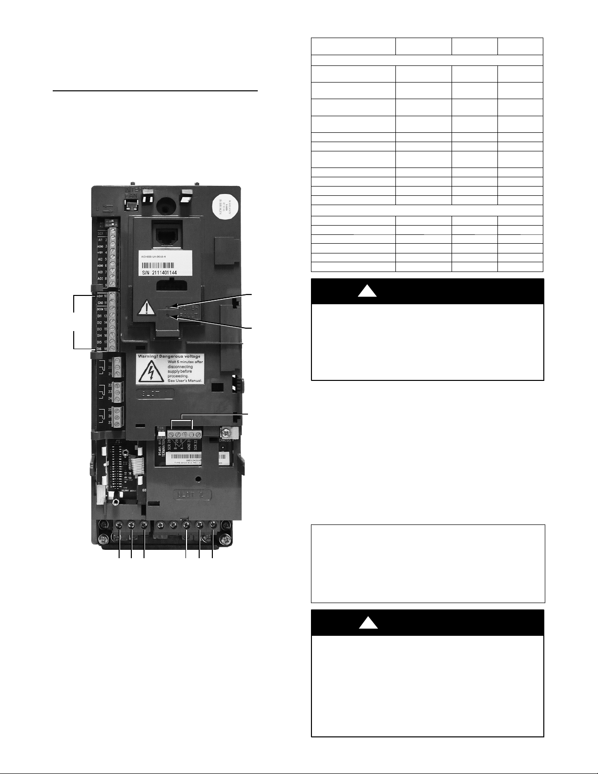
Variable Frequency Drive (VFD)
VFDs are available as a factory--installed option for LC series
units. Size 04--06 units use ABB VFDs while sizes 07--26 use
Danfoss VFDs. For details on size 07 --26 units with VFDs
continue at page 65.
LC 04--06 Variable Frequency Drive (ABB VFD)
On units equipped with supply fan VFDs, the indoor fan motor is
controlled by a 3-phase VFD. The supply fan VFD is located in the
supply fan section behind the access door. These units use ABB
VFDs. The VFD varies the frequency of the AC voltage supplied
to the indoor fan. This allows the variance in the speed of the fan.
The VFD is always powered during normal operation and the fan
is stopped by driving the speed to 0. Fig. 37 and Table 27 show the
VFD terminals and connections.
Table 27 – LC 0 4--06 VFD Connections
POINT DE SCRIPTION TYPE OF I/O
Low Volta ge Power
(jumped to DI1 & DI4)
Low Voltage Common
(jumped to DCOM)
Discrete Inputs Common
(jumped from GND)
Discrete Input 1
(jumped from 24v)
Not Used Switch Input 14 DI2
Not Used Switch Input 15 DI3
Discrete Input 4
(jumped from 24v)
Shielded Cable Ground Shield 28 SCR
LEN communicat ion LEN 29 B+
LEN communicat ion LEN 30 A --LEN Communicat ion LEN 31 AGND
Vo l t a g e L e g f r o m C --- 1 1 Voltage Input U1 MAINS
Vo l t a g e L e g f r o m C --- 1 3 Voltage Input V1 MAINS
Volta ge Le g f ro m IFT B Voltage Input W1 MAINS
Vo l t a g e L e g t o I F M --- 3 Volta ge Output U2 MOTOR
Vo l t a g e L e g t o I F M --- 2 Volta ge Output V2 MOTOR
Vo l t a g e L e g t o I F M --- 1 Volta ge Output W2 MOTOR
LOW VOLTAGE INPUTS
24vdc 10 24v
Ground 11 GND
Ground 12 DCOM
Switch Input 13 DI1
Switch Input 16 DI4
HIGH VOLTAGE
TERMINAL
NUMBER
TERMINAL
NAME
POWER
LED
TERMINALS
10 – 16
U1 V1 W1 U2 V2 W2
FAULT
LED
TERMINALS
28 – 31
C12225
Fig. 37 -- LC 04--06 Variable Frequency Drive (VFD) Termin-
als and Connections -- unit shown front cover removed
!
CAUTION
EQUIPMENT DAMAGE/PERFORMANCE HAZARD
Failure to follow this caution may result in damage to the unit
or in degradation of unit performance.
Do not run the Carrier Assistant through the VFD keypad.
This will cause parameters to change value that are not desired
on these applications.
The VFDs communicate to the MBB over the local equipment
network (LEN). The VFD speed is controlled directly by the
SystemVut controller over the LEN. The VFD parameters
required to allow the VFD to communicate on the LEN are shown
in Table 28. Table 29 shows VFD parameters that are hard--coded
by the SystemVu controller. The parameters listed in Table 30 have
corresponding SystemVu configurations (SETTINGS UNIT
CONFIGURATIONS INDOOR FAN IFD VFD
PARAMETERS). The factory sets these parameters per motor
installed in the unit and these should not be adjusted in the field.
These are only provided for drive or motor replacement. These
parameters in Table 30 require the drive to be off or 0% to change
them.
IMPORTANT: If the VFD appears to be communicati ng (the VFD
software version can be read in SERVICE UNIT
INFORMA TI ON VERSIONS) but the loss of communications
fault persist s, place the keypad in t he Off stat e. If communicat ion is
reestablished the VFD had to be in the Off state to save the
configurations being sent.
This can occur after a VFD is replaced.
The VFD is factory–configured to match the current and power
requirements for each motor selection and all wiring connections
are completed by the factory; no field adjustments or connections
are necessary. While the basic VFD retains all of its standard
capabilities, this application uses only a limited portion of these
features to provide discrete output speeds to the motor.
Consequently the VFD is not equipped with a keypad. A keypad is
available as an accessory (P/N: CRDISKIT001A00) for field
installation or expanded service access to VFD parameter and
troubleshooting tables. The VFD used has soft start capabilities to
slowly ramp up the speeds, eliminating any high inrush of air
volume during speed changes.
!
WARNING
EQUIPMENT DAMAGE HAZARD
Failure to follow this warning could result in equipment
damage.
The VFD motor parameters shown in Table 32 should never be
changed in the field unless authorized by Carrier Corporation.
Damage could occur to the motor or unit if these are set to
anything besides what is shown in the table. These are only
provided for drive or motor replacement or future adjustments.
61
Page 62
Table 28 – LC 04--06 VFD Parameters Configured by Factory or VFD Keypad
Parameter Group Parameter Title ABB Parameter HVAC Default CARRIER
Options COMM PROT SEL 9802 NOT SEL LEN (6 )
EFB PROTOCOL ID 5301 0000 hex 0601 hex
EFB STATION ID 5302 0 41
EFB Protocol
EFB BAUD RATE 5303 9.6 kb/s 38.4 kb/s
EFB PARITY 5304 8NONE1 8NONE1
EFB CTRL PROFILE 5305 ABB DRV LIM DCU PROFILE
Table 29 – LC 04--06 VFD Parameters Hard Coded by SystemVut Controller
Parameter Group Parameter Title ABB Parameter HVAC Default CARRIER
Start/Stop/Dir EXT1 COMMANDS 1001 DI1 COMM (2)
Reference Select REF1 SELECT 1103 AI1 COMM (2)
Constant Speeds CONST SPEED 7 1208 60 Hz 0Hz
RUN ENABLE 1601 NOT SEL NOT SEL (0)
System Controls
Start/Stop
Fault Functions
Start/Stoop/Dir DIRECTION 1003 FORWARD REQUEST
Accel/Decel
Motor Control SWITCHING FREQ 2606 4kHz 4kHz
S t a r t --- U p D a t a
Limits MAXIMUM CURRENT 2003 1.3*i2n Se e Table 32
FAULT RESET SEL 1604 KEYPAD COMM (7)
START ENABLE 1 1608 DI4 DI4 (4)
START FUNCTION 2101 SCALAR FLYSTART AUTO (0)
STOP FUNCTION 2102 COAST COAST (1)
COMM FAULT FUNC 3018 NOT SEL CONST SP 7 (2)
COMM FAULT TIME 3019 10.0 s 10.0 s
ACCELER TIME 1 2202 30.0s 30.0s
DECELER TIME 1 2203 30.0s 10.0s
MOTOR NOM VOLT 9905 230V, 460V, 575V See T able 32
MOTOR NOM CURR 9906 10*In See Table 32
MOTOR NOM FREQ 9907 60 Hz 60 Hz
MOTOR NOM SPEED 9908 1750 rpm See Table 32
MOTOR NOM POWER 9909 1.0*Pn See Table 32
Table 30 – LC 04--06 VFD Parameters Configurable Through SystemVu Controller
Param eter
Group
Accel/Decel
S t a r t --- U p D a t a
Limits MAXIMUM CURRENT 2003 1.3*I2n See Table 32 CURRLMT IDF VFD MAX AMPS
Param eter Ti tle ABB Parameter HVAC Default CARRIER CCN POINT Display Menu Item
ACCELER TIME 1 2202 30.0s 30.0s RAMPUP_T VFD ACCEL TIME
DECELER TIME 1 2203 30.0s 10.0s RAMPDN_T VFD DECEL TIME
MOTOR NOM VOLT 9905 230V,460V,575V See Table 32 MOTVOLT IDF VFD VOLTAGE
MOTOR NOM CURR 9906 1.0*In See Table 32 MOTCUR IDF VFD NOM. AMPS
MOTOR NOM FREQ 9907 60 Hz 60 Hz MOTFREQ IDF VFD NOM. FREQ
MOTOR NOM SPEED 9908 1750 rpm See Table 32 MOTNOMSP IDF VFD NOM. RPM
MOTOR NOM
POWER
9909 1.0*Pn See Table 32 MOTPWRHP IDF VFD NOM. HP
Table 31 – LC 04--06 VFD Status Parameters Available Through System Vu Controller
Parameter Group Parameter Tit le ABB Parameter Units SystemVu Point SystemVu Display Item
Run Time 0114 h RUNHOURS IDF VFD RUN HOURS
KWh Counter 0115 kWh KWHCNTR IDF VFD KW HOURS
Powe r 0106 kW OUTPWRKW VFD OUTPUT KW
Operating Data
Output Voltage 0109 V OUTMVOLT VFD OUTPUT VOLTS
Output Frequency 0103 Hz OUTMFREQ VF D OUTPUT FREQ
CURRENT 0104 A OUTMCUR VFD OUTPUT AMPS
DC Bus Voltage 0107 V DLCNVOLT IDF VFD DC VOLTS
Drive Temp 0110 _C HTSINKT IDF VFD HSNK TEMP
62
Page 63
Table 32 – LC 04--06 VFD Motor Default Configurations
EQUIPMENT MODEL NUMBER (EQ_MOD)
Position 1,2 Position 7,8 Position 10 Position 12 MOTPWRHP MOTVOLT MOTCUR MOTNOMSP VFD1MAXA
48 04 2 5 1.7 230 5.8 1725 6.7
48 04 2 6 1.7 460 2.9 1725 3.3
48 04 2 1 1.7 575 3.1 1725 3.6
48 04 3 5 2.4 230 7.9 1725 9.1
48 04 3 6 2.4 460 2.9 1725 4.6
48 04 3 1 2.4 575 3.4 1725 3.9
48 05 2 5 1.7 230 5.8 1725 6.7
48 05 2 6 1.7 460 2.9 1725 3.3
48 05 2 1 1.7 575 3.1 1725 3.6
48 05 3 5 2.9 230 9.2 1725 10.6
48 05 3 6 2.9 460 4.6 1725 5.3
48 05 3 1 3.7 575 4.2 1725 4.8
48 06 2 5 2.4 230 7.9 1725 9.1
48 06 2 6 2.4 460 4 1725 4.6
48 06 2 1 2.4 575 3.4 1725 3.9
48 06 3 5 2.9 230 9.2 1725 10.6
48 06 3 6 2.9 460 4.6 1725 5.3
48 06 3 1 3.7 575 4.2 1725 4.8
50 04 2 5 1.7 230 5.8 1725 6.7
50 04 2 6 1.7 460 2.9 1725 3.3
50 04 2 1 1.7 575 3.1 1725 3.6
50 04 3 5 2.4 230 7.9 1725 9.1
50 04 3 6 2.4 460 2.9 1725 4.6
50 04 3 1 2.4 575 3.4 1725 3.9
50 05 2 5 1.7 230 5.8 1725 6.7
50 05 2 6 1.7 460 2.9 1725 3.3
50 05 2 1 1.7 575 3.1 1725 3.6
50 05 3 5 2.9 230 9.2 1725 10.6
50 05 3 6 2.9 460 4.6 1725 5.3
50 05 3 1 3.7 575 4.2 1725 4.8
50 06 2 5 2.4 230 7.9 1725 9.1
50 06 2 6 2.4 460 4 1725 4.6
50 06 2 1 2.4 575 3.4 1725 3.9
50 06 3 5 2.9 230 9.2 1725 10.6
50 06 3 6 2.9 460 4.6 1725 5.3
50 06 3 1 3.7 575 4.2 1725 4.8
Nominal
Horse Power
Motor Voltage
Motor Current
( M u s t --- H o l d
Amps)
Motor Nominal
Speed
VFD Max A m ps
For proper operation, there are three jumper wires that must
remain installed an d the VFD must be set to the auto mode. The
3 jumpers are shown on the unit schematic and are connected
through a plug called PL25. These jumpers set the VFD to start
enabled, run enabled, and tie the common bus together. The
VFD has 2 LEDs on its front panel to indicate operating status.
See below and VFD Troubleshooting section for details on VFD
faults and alarms. The VFD faults can be reset with the VFD
keypad or through the SystemVut controller
(ALERTS/FAULTS RESET FAULT/ALERT = Yes).
The Green LED on steady indicates power is on the VFD, flashing
Green indicates an alarm condition detected. Alarms are advisory
in nature. These indicate a problem has been detected by the VFD’s
diagnostics but this problem will not require a shutdown.
The Red LED steady or flashing indicates a fault condition is
detected. A fault is a significant internal situation for the VFD or
Motor. Faults will typically shutdown the motor.
LC 04--06 VFD Troubleshooting
When communication is successful, the SystemVut control will
provide alerts and faults that correlate to the VFD’s warnings and
alarms. Table 33 shows the list of the SystemVu controller faults
and alerts and how they map to the VFD warnings and alarms.
Table 33 also lists the possible causes of these cases.
VFD Diagnostics (with Keypad)
The drive detects error situations and reports them using:
1. Green and red LEDs on the body of the drive (located under
the keypad)
2. Status LED on the control panel
3. Control panel display
4. The Fault Word and Alarm Word parameter bits (parameters
0305 to 0309)
The form of t he display depends on the s everity of t he error. The user
can specify the severity for many errors by directing the drive to
ignore the error situati on, report the situation as an alarm, or report the
situation as a fault.
Faults (Red LED Lit)
The VFD signals that it has detected a severe error, or fault, by:
1. Enabling the red LED on the drive (LED is either steady or
flashing)
2. Setting an appropriate bit in a Fault Word parameter (0305
to 0307)
63
Page 64
3. Overriding the control panel display with the display of a
fault code
4. Stopping the motor (if it was on)
5. Sets an appropriate bit in Fault Word parameter (0305 to
0307)
The fault code on the control panel display is temporary. Pressing
the MENU, ENTER, UP or DOWN buttons removes the fault
message. The message reappears after a few seconds if the control
panel is not touched and the fault is still active.
Alarms (Green LED Flashing)
For less severe errors, called alarms, the diagnostic display is
advisory. For these situations, the drive is simply reporting that it
had detected something unusual. In these situations, the drive:
1. Flashes the green LED on the drive (does not apply to
alarms that arise from control panel operation errors)
2. Sets an appropriate bit in an Alarm Word parameter (0308
or 0309)
3. Overrides the control panel display with the display of an
alarm code and/or name
Alarm messages disappear from the control panel display after a
few seconds. The message returns periodically as long as the alarm
condition exists.
Correcting Faults
The recommended corrective action for faults is shown in the Fault
Listing Table 33. The VFD can also be reset to remove the fault. If
an external source for a start command is selected and is active, the
VFD may start immediately after fault reset.
To reset a fault indicated by a flashing red LED, turn off the power
for 5 minutes. To reset a fault indicated by a red LED (not
flashing), press RESET from the control panel or turn off the
power for 5 minutes. Depending on the value of parameter 1604
(FAULT RESET SELECT), digital input or serial communication
could also be used to reset the drive. When the fault has been
corrected, the motor can be started.
History
For reference, the last three fault codes are stored into parameters
0401, 0412, 0413. For the most recent fault (identified by
parameter 0401), the drive stores additional data (in parameters
0402 through 0411) to aid in troubleshooting a problem. For
example, a parameter 0404 stores the motor speed at the time of the
fault. To clear the fault history (all of Group 04, Fault History
parameters), follow these steps:
1. In the control panel, Parameters mode, select parameter
0401.
2. Press EDIT.
3. Press the UP and DOWN buttons simultaneously.
4. Press SAVE.
If diagnostics troubleshooting has determined that the drive is
defective during the warranty period, contact ABB Automation
Inc., at 1--800--435 --7365, option 4, option 3. A qualified
technician will review the problem with the caller and make a
determination regarding how to proceed. This may involve
dispatching a designated service station (DSS) representative from
an authorized station, dispatching a replacement unit, or advising
return for repair.
Table33–LC04--06VFDFaultCodes
SystemVu Fault SystemVu A lert ABB Alarm Code Alarm Description Cause of Problem and Corrective Action
F613--- IDF VFD
OVER CURRENT
F617--- IDF VFD
OVER VOLTAGE
F601--- IDF VFD
UNEXPECTED
F618--- IDF VFD
SHORT CIRCUIT
F616--- IDF VFD
UNDER VOLTAGE
F614--- IDF VFD
MOTOR OVER TEMP
F611--- IDF VFD
EARTH FAULT
F619--- IDF VFD
MAIN PHASE LOSS
A607--- IDF VFD
CURRENT LIMIT
A606--- IDF VFD
VOLTAGE WARNING
A605--- IDF VFD
THERMAL WARNING
--- 4 Short Circuit
A606--- IDF VFD
VOLTAGE WARNING
A605--- IDF VFD
THERMAL
WARNING
A608--- IDF VFD
WARNING
A608--- IDF VFD
WARNING
1 Over Current
2 DC Over Voltage
3 Device Over Temp
6 DC Under Volt
9 MotorOverTemp
16 Earth Fault
22 Supply Phase
Output current is e xcessive. Check for excessive motor load, insufficient
acceleration time (parameters 2202 ACCELER TIME 1, default 30 seconds),
or fault y moto r, motor cables or connections.
Intermediate circui t DC voltage is excessive. Check for static or transient over
voltages in the input power supply, insufficient deceleration time (parameters 2203
DECELE R TIME 1, default 30 seconds) , or undersiz ed brake chopper (if present).
Drive heat sink is overheated. Temperature is at or above 115° C (239° F).
Check for fan failure, obstructions in the air flow, dirt or dust coating on the
heat sink, excessive ambient tempe rature, or exce ssive mot or load.
Fault current. Check fo r short - -- circuit in the motor cable(s) or motor or
supply dist urbances.
Intermediate circuit DC voltage is not sufficient. Check for missing phase in
the input power supply, blown fuse, or under voltage on main circuit.
Motor is too hot, as estimated by the drive. Check for overloaded motor.
Adjust the parameters used for t he estimate (3005 through 3009). Check the
temperature sensors and Group 35 paramet ers.
The load on the input power system is out of balance. Check for faults in the
motor or motor cable. Verify that motor cable does not exceed maximum
specified length.
Ripple voltage in the DC link is to o high. Check for missing main phase or
blown fuse.
64
Page 65
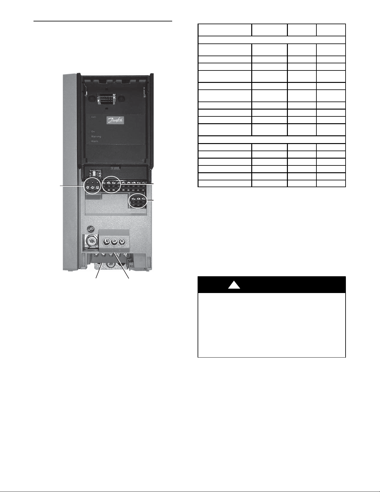
LC 07--26 Variable Frequency Drive (Danfoss VFD)
The indoor fan motor is controlled by a VFD. The supply fan VFD
is located in the supply fan section behind the access door. The
VFD varies the frequency of the AC voltage supplied to the indoor
fan. This allows the variation in the speed of the fan. The VFD is
always powered during normal operation and the fan is stopped by
driving the speed to 0. Fig. 38 and Table 34 show the VFD
terminals and connections.
TERMINALS
61, 68, 69
TERMINALS
U, V, W
TERMINALS
L1, L2, L3
Fig. 38 -- Variable Frequency Drive (VFD) Terminals and
Connections -- unit shown with front cover removed
The VFD is factory–configured to match the current and power
requirements for each motor selection and all wiring connections
are completed by the factory; no field adjustments are necessary.
The VFD used has soft start capabilities to slowly ramp up the
speeds, eliminating any high inrush of air volume during speed
changes. While the basic VFD retains all of its standard
capabilities, the LC unit uses only a limited portion of these
features to provide discrete output speeds to the motor. The VFD is
not equipped with a keypad. A keypad is available as an accessory
(P/N: CRDISKIT002A00) for field installation or expanded
service access to VFD parameter and troubleshooting tables.
TERMINALS
18, 19, 27, 29
TERMINALS
12, 20, 55
C14334
Table 34 – VFD Connections
POINT DE SCRIPTION TYPE OF I/O
LOW VOLTAGE INPUTS
Low Volta ge Power
(jumped to 18 & 27)
Discrete Inputs Common Ground 20 GND
Analog Inputs Common Ground 55 GND
Terminal 18 Discrete Input
(jumped from 24v)
Not Used Sw itch Input 19 DIG IN
Terminal 27 Discrete Input
(jumped from 24v)
Not Used Sw itch Input 29 DIG IN
LEN communicat ion + LEN+ 68 P
LEN communicat ion --- L E N --- 69 N
LEN Communicat ion
Common
Vo l t a g e L e g f r o m C --- 1 1 Voltage Input L1 MAINS
Vo l t a g e L e g f r o m C --- 1 3 Voltage Input L2 MAINS
Volta ge Le g f ro m IFT B Voltage Input L3 MAINS
Vo l t a g e L e g t o I F M --- 3 Voltage O utput U MOTOR
Vo l t a g e L e g t o I F M --- 2 Voltage O utput V MOTOR
Vo l t a g e L e g t o I F M --- 1 Voltage O utput W MOTOR
24vdc 12 +24v
Switch Input 18 DIG IN
Switch Input 27 DIG IN
LEN C 61 COMM. GND
HIGH VOLTAGE
TERMINAL
NUMBER
TERMINAL
NAME
The VFD communicate to the MBB over the local equipment
network (LEN). The VFD speed is controlled directly by the
controller over the LEN. The VFD parameters required for the
VFD to communicate on the LEN are shown in Table 35. Table 36
shows VFD parameters that are hard-coded by the SystemVut
controller. The parameters listed in Table 37 have corresponding
SystemVu controller configurations (SETTINGS UNIT
CONFIGURATIONS INDOOR FAN IFD VFD
PARAMETERS). The factory sets these parameters per the motor
installed in the unit and these should not be adjusted in the field.
These are only provided for drive or motor replacement. These
parameters in Table 37 require the drive to be off or 0% to change
them.
!
WARNING
EQUIPMENT DAMAGE HAZARD
Failure to follow this warning could result in equipment
damage.
The VFD motor parameters shown in Table 39 should never be
changed in the field unless authorized by Carrier Corporation.
Damage could occur to the motor or unit if these are set to
anything besides what is shown in the table. These are only
provided for drive or motor replacement or future adjustments.
65
Page 66
Table 35 – LC 07--26 VFD Parameters Configured by Factory or VFD Keypad
Parameter Group Parameter Title Danfoss Parameter VFD D efault CARRIER
Reset Funct ions Service Code 14--- 29 6333 6222
PROTOCOL 8 --- 3 0 (0) FC (20) LEN
FC Port Settings
ADDRESS 8 --- 3 1 1 180
BAUD RATE 8 --- 3 2 (2) 9.6 kb/s (4) 38.4 kb/s
Parity/Stop Bits 8 --- 3 3 (0) 8 EVEN 1 (2) 8 NONE 1
Table 36 – LC 07--26 VFD Parameters Hard Coded by SystemVut Controller
Parameter Group Parameter Title Danfoss Parameter VFD D efault CARRIER
Basic Settings Regional Settings 0 --- 0 3 International (0) North America (1)
Configuration Mode 1 --- 0 0 Open Loop (0) Open Loop (0)
General Settings
Motor Selection Mo tor Co nstruction 1 --- 1 0 Asynchron (0) Asynchron (0)
Start Adjustments
Motor Temperature Motor Thermal Protection 1 --- 9 0 No Protection (0) ETR trip 1 (4)
Brake Energy Funct. Over--- voltage Control 2 --- 1 7 Enabled (2) Enabled (2)
References
Motor Limits
Digital Inputs
Relays
Analog/Digital Output
Analog/Digital Output
General Settings
Digital/Bus Start Select 8 --- 5 3 Logic OR (3) Logic AND (2)
SLC Settings SL Controller Mode 13--- 00 Off (0) Off (0)
Inverter Switching Switching Frequency 14 --- 01 5.0khz (5) 5.0khz (5)
Mains On/Off Function at Mains Imbalance 14--- 12 Tri p (0 ) Tr ip ( 0 )
Reset Funct ions Reset Mode 14---20 Manual Reset (0) Automatic reset x 3 (3)
Torque Characteristics 1 --- 0 3 Variable Torque (1) Variable Torque (1)
Clockwise Direction 1 --- 0 6 Normal (0) Normal (0)
Start Delay 1 --- 7 1 0s 0s
Start Function 1 --- 7 2 Coast/dela y time (2) Coast/delay time (2)
Flying Start 1 --- 7 3 Disabled (0) Disabled (0)
Preset Reference 3 --- 1 0 %00005 %00005
Reference 3 Source 3 --- 1 7 Local bus reference (11) Local bus reference (11)
Motor Speed Direction 4 --- 1 0 Both directions (2) Both directions (2)
Motor Speed Low Limit [Hz] 4 --- 1 2 0hz 0hz
Motor Speed High Limit [Hz] 4 --- 1 4 65hz 65hz
T erminal 18 Digit al Input 5 --- 1 0 8 Start (8)
T erminal 27 Digit al Input 5 --- 1 2 Coast Inverse (2) No Opera tion (0)
Function Relay (Rela y 1) 5 --- 4 0 No Function (0) Bus Control (45)
Function Relay (Rela y 2) 5 --- 4 0 No Function (0) Bus Control (45)
Te r m i n a l 4 5 M o de 6 --- 7 0 0 --- 2 0 m A ( 0 ) 4 --- 2 0 mA (1 )
Terminal 45 Analog Output 6 --- 7 1 No Operation (0) Bus Control (139)
Te r m i n a l 4 5 O ut put Mi n S c a l e 6 --- 7 3 %00005 %00005
Te r m i n a l 4 2 M o de 6 --- 9 0 0 --- 2 0 m A ( 0 ) 0 --- 2 0 mA (0 )
Terminal 42 Analog Output 6 --- 9 1 No Operation (0) Bus Control (139)
Te r m i n a l 4 2 O ut put Mi n S c a l e 6 --- 9 3 %00005 %00005
Control Site 8 --- 0 1 Digital and ctrl.word (0) Digital and ctrl.word (0)
Control Source 8 --- 0 2 FC Port (1) FC Port (1)
Control Timeout Function 8 --- 0 4 Off (0) Stopandtrip(5)
Table 37 – LC 07--26 VFD Parameters Configurable Through SystemVu Controller
Param eter
Group
Motor Data
Reference Limits
Ramp 1
Motor Limits Current Limit 4 --- 1 8 110% 100% CURRLMT IDF VFD AMP LIMIT
General Settings Cont rol Timeout Time 8 --- 0 3 1s 30s CNT_TOUT IDF VFD TIMEOUT
Reset Funct ions Automatic Restart Time 14--- 21 10s 30s ARSTRT_T IDF VFD RESET DUR
Environment RFI Filter 14 --- 50 On (1) On (1) RFIFILTR VFD RFI FILTER
Param eter Ti tle
Motor Power 1 --- 2 0 drive dep. See Tabl e 39 or 40 MOTPHP IDF VFD NOM HP
Motor Voltage 1 --- 2 2 drive dep. See T abl e 39 or 40 MOTVOLT IDF VFD VOLTAGE
Motor Frequency 1 --- 2 3 50hz 60hz MOTFREQ IDF VFD NOM. FREQ
Motor Current 1 --- 2 4 drive dep. See T able 39 or 40 MOTCUR IDF VFD NOM. AMPS
Motor Nominal Speed 1 --- 2 5 drive dep. See T abl e 39 or 40 MOTNOMSP IDF VFD NOM. RPM
Minimum Reference 3 --- 0 2 0hz 0hz MINREF IDF VFD MIN REF
Maximum Reference 3 --- 0 3 50hz 60hz MAXREF IDF VFD MAX REF
Ramp1RampUpTime 3 --- 4 1 3s 10s RAMPUP_T VFD ACCEL. TIME
Ramp 1 Ramp Down Time 3 --- 4 2 3s 30s RAMPDN_T VFD DECEL. TIME
Danfoss
Param eter
HVAC Default CARRIER CCN Point Display Menu Item
66
Page 67
Table 38 – LC 07--26 VFD Status Parameters Available Through SystemVut Controller
Parameter Group Parameter Tit le Danfoss Parameter Units SystemVu Point SystemVu Display Item
Operating Data
General Status
Motor Status
Drive Status
Diagnostic Readouts Alarm Word 16--- 90 ALMERRC IDF VFD ALM WORD
NOTE: Table 38 lists the status information the VFD sends to the SystemVu controls. This table is updated at every scan the controls perform of the LEN.
This occurs approximately once every second.
Running Hours 15 --- 01 h RUNHOURS IDF VFD RUN HOURS
kWh Counter 15--- 02 kWh KWHCNTR IDF VFD KW HOURS
Reference [%] 16 --- 02 % REFSPEED VFD REF SPEED
Status Word 16---03 STATUSWD VF D STATUS WORD
Main Actual Value [%] 16--- 05 % MAV IDF VFD FEEDBACK
Powe r [ kW] 16--- 10 kW OUTPWRKW VFD OUTPUT KW
Powe r [ hp] 16--- 11 hp OUTPWRHP VFD OUTPUT HP
Motor Voltage 16--- 12 V OUTMVOLT VFD OUTPUT VOLTS
Frequency 16--- 13 Hz OUTMFREQ VFD OUTPUT FREQ
Motor current 16 ---14 A OUTMCUR VFD OUTPUT AMPS
DC Link Voltage 16--- 30 V DCLNVOLT IDF VFD DC VOLTS
Heatsink Temp. 16 --- 34 °C HTSINKT IDF VFD HSNK TEMP
Table 39 – LC 07--26 VFD Motor Default Configurations -- Vertical Airflow Units
EQUIPMENT MODEL NUMBER (EQ_MOD)
Position 1,2 Position 7,8 Position 10 Position 12 MOTPWRHP MOTVOLT MOTCUR MOTNOMSP VFD1MAXA
48 07 1 5 1.7 230 5.8 1695 5.8
48 07 1 6 1.7 460 2.9 1690 2.9
48 07 1 1 1.7 575 3.1 1690 3.1
48 07 2 5 1.7 230 5.8 1695 5.8
48 07 2 6 1.7 460 2.9 1690 2.9
48 07 2 1 1.7 575 3.1 1690 3.1
48 07 3 5 2.9 230 9.2 1735 9.2
48 07 3 6 2.9 460 4.2 1735 4.2
48 07 3 1 2.9 575 4.9 1710 4.9
48 08 1 5 1.7 230 5.8 1695 5.8
48 08 1 6 1.7 460 2.9 1690 2.9
48 08 1 1 1.7 575 3.1 1690 3.1
48 08 2 5 2.4 230 7.9 1680 7.9
48 08 2 6 2.4 460 3.6 1680 3.6
48 08 2 1 2.4 575 3.8 1680 3.8
48 08 3 5 3.7 230 11.7 1750 11.7
48 08 3 6 3.7 460 5.4 1750 5.4
48 08 3 1 3.7 575 4.9 1710 4.9
48 08 4 5 5.0 230 13.6 1745 13.6
48 08 4 6 5.0 460 6.8 1745 6.8
48 08 4 1 5.0 575 6 1745 6.0
48 09 1 5 1.7 230 5.8 1695 5.8
48 09 1 6 1.7 460 2.9 1690 2.9
48 09 1 1 1.7 575 3.1 1690 3.1
48 09 2 5 2.4 230 7.9 1680 7.9
48 09 2 6 2.4 460 3.6 1680 3.6
48 09 2 1 2.4 575 3.8 1680 3.8
48 09 3 5 3.7 230 11.7 1750 11.7
48 09 3 6 3.7 460 5.4 1750 5.4
48 09 3 1 3.7 575 4.9 1710 4.9
48 09 4 5 5.0 230 13.6 1745 13.6
48 09 4 6 5.0 460 6.8 1745 6.8
48 09 4 1 5.0 575 6 1745 6.0
48 12 1 5 2.4 230 7.9 1680 7.9
48 12 1 6 2.4 460 3.6 1680 3.6
48 12 1 1 2.4 575 3.8 1680 3.8
48 12 2 5 3.7 230 11.7 1750 11.7
48 12 2 6 3.7 460 5.4 1750 5.4
48 12 2 1 3.7 575 4.9 1710 4.9
48 12 3 5 5.0 230 13.6 1745 13.6
48 12 3 6 5.0 460 6.8 1745 6.8
48 12 3 1 5.0 575 6 1745 6.0
Nominal
Horse Power
Motor Voltage
Motor Current
( M u s t --- H o l d
Amps)
Motor Nominal
Speed
VFD Max A m ps
67
Page 68
Table 39 -- LC 07 --26 VFD Motor Default Configurations -- Vertical Airflow Units (cont)
EQUIPMENT MODEL NUMBER (EQ_MOD)
Position 1,2 Position 7,8 Position 10 Position 12 MOTPWRHP MOTVOLT MOTCUR MOTNOMSP VFD1MAXA
48 14 1 5 2.9 230 9.2 1735 9.2
48 14 1 6 2.9 460 4.2 1735 4.2
48 14 1 1 2.9 575 4.9 1710 4.9
48 14 2 5 5.0 230 13.6 1745 13.6
48 14 2 6 5.0 460 6.8 1745 6.8
48 14 2 1 5.0 575 6 1745 6.0
48 14 3 5 7.5 230 21.2 1760 21.2
48 14 3 6 7.5 460 9.7 1760 9.7
48 14 3 1 7.5 575 7.2 1745 7.2
48 14 4 5 10.0 230 28 1760 28.0
48 14 4 6 10.0 460 13.7 1760 13.7
48 14 4 1 10.0 575 8.9 1750 8.9
48 17 1 5 2.9 230 9.2 1735 9.2
48 17 1 6 2.9 460 4.2 1735 4.2
48 17 1 1 2.9 575 4.9 1710 4.9
48 17 2 5 7.5 230 21.2 1760 21.2
48 17 2 6 7.5 460 9.7 1760 9.7
48 17 2 1 7.5 575 7.2 1745 7.2
48 17 3 5 10.0 230 28 1760 28.0
48 17 3 6 10.0 460 13.7 1760 13.7
48 17 3 1 10.0 575 8.9 1750 8.9
48 17 4 5 15.0 230 37.3 1755 37.3
48 17 4 6 15.0 460 16.9 1755 16.9
48 17 4 1 15.0 575 12.6 1755 12.6
48 20 1 5 2.9 230 11.7 1750 11.7
48 20 1 6 2.9 460 5.4 1750 5.4
48 20 1 1 2.9 575 4.9 1710 4.9
48 20 2 5 7.5 230 21.2 1760 21.2
48 20 2 6 7.5 460 9.7 1760 9.7
48 20 2 1 7.5 575 7.2 1745 7.2
48 20 3 5 10.0 230 28 1760 28.0
48 20 3 6 10.0 460 13.7 1760 13.7
48 20 3 1 10.0 575 8.9 1750 8.9
48 20 4 5 15.0 230 37.3 1755 37.3
48 20 4 6 15.0 460 16.9 1755 16.9
48 20 4 1 15.0 575 12.6 1755 12.6
48 24 1 5 7.5 230 21.2 1760 21.2
48 24 1 6 7.5 460 9.7 1760 9.7
48 24 1 1 7.5 575 7.2 1745 7.2
48 24 2 5 10.0 230 28 1760 28.0
48 24 2 6 10.0 460 13.7 1760 13.7
48 24 2 1 10.0 575 8.9 1750 8.9
48 24 3 5 15.0 230 37.3 1755 37.3
48 24 3 6 15.0 460 16.9 1755 16.9
48 24 3 1 15.0 575 12.6 1755 12.6
48 26 1 5 7.5 230 21.2 1760 21.2
48 26 1 6 7.5 460 9.7 1760 9.7
48 26 1 1 7.5 575 7.2 1745 7.2
48 26 2 5 10.0 230 28 1760 28.0
48 26 2 6 10.0 460 13.7 1760 13.7
48 26 2 1 10.0 575 8.9 1750 8.9
48 26 3 5 15.0 230 37.3 1755 37.3
48 26 3 6 15.0 460 16.9 1755 16.9
48 26 3 1 15.0 575 12.6 1755 12.6
Nominal
Horse Power
Motor Voltage
Motor Current
( M u s t --- H o l d
Amps)
Motor Nominal
Speed
VFD Max A m ps
68
Page 69
Table 39 -- LC 07 --26 VFD Motor Default Configurations -- Vertical Airflow Units (cont)
EQUIPMENT MODEL NUMBER (EQ_MOD)
Position 1,2 Position 7,8 Position 10 Position 12 MOTPWRHP MOTVOLT MOTCUR MOTNOMSP VFD1MAXA
50 07 1 5 1.7 230 5.8 1695 5.8
50 07 1 6 1.7 460 2.9 1690 2.9
50 07 1 1 1.7 575 3.1 1690 3.1
50 07 2 5 1.7 230 5.8 1695 5.8
50 07 2 6 1.7 460 2.9 1690 2.9
50 07 2 1 1.7 575 3.1 1690 3.1
50 07 3 5 2.9 230 9.2 1735 9.2
50 07 3 6 2.9 460 4.2 1735 4.2
50 07 3 1 2.9 575 4.9 1710 4.9
50 08 1 5 1.7 230 5.8 1695 5.8
50 08 1 6 1.7 460 2.9 1690 2.9
50 08 1 1 1.7 575 3.1 1690 3.1
50 08 2 5 1.7 230 5.8 1695 5.8
50 08 2 6 1.7 460 2.9 1690 2.9
50 08 2 1 1.7 575 3.1 1690 3.1
50 08 3 5 2.9 230 9.2 1735 9.2
50 08 3 6 2.9 460 4.2 1735 4.2
50 08 3 1 2.9 575 4.9 1710 4.9
50 08 4 5 3.7 230 13.6 1745 13.6
50 08 4 6 3.7 460 6.8 1745 6.8
50 08 4 1 3.7 575 6 1745 6.0
50 09 1 5 1.7 230 5.8 1695 5.8
50 09 1 6 1.7 460 2.9 1690 2.9
50 09 1 1 1.7 575 3.1 1690 3.1
50 09 2 5 1.7 230 5.8 1695 5.8
50 09 2 6 1.7 460 2.9 1690 2.9
50 09 2 1 1.7 575 3.1 1690 3.1
50 09 3 5 3.7 230 11.7 1750 11.7
50 09 3 6 3.7 460 5.4 1750 5.4
50 09 3 1 3.7 575 4.9 1710 4.9
50 09 4 5 5.0 230 13.6 1745 13.6
50 09 4 6 5.0 460 6.8 1745 6.8
50 09 4 1 5.0 575 6 1745 6.0
50 12 1 5 2.4 230 7.9 1680 7.9
50 12 1 6 2.4 460 3.6 1680 3.6
50 12 1 1 2.4 575 3.8 1680 3.8
50 12 2 5 2.9 230 9.2 1735 9.2
50 12 2 6 2.9 460 4.2 1735 4.2
50 12 2 1 2.9 575 4.9 1710 4.9
50 12 3 5 5.0 230 13.6 1745 13.6
50 12 3 6 5.0 460 6.8 1745 6.8
50 12 3 1 5.0 575 6 1745 6.0
50 14 1 5 2.9 230 9.2 1735 9.2
50 14 1 6 2.9 460 4.2 1735 4.2
50 14 1 1 2.9 575 4.9 1710 4.9
50 14 2 5 5.0 230 13.6 1745 13.6
50 14 2 6 5.0 460 6.8 1745 6.8
50 14 2 1 5.0 575 6 1745 6.0
50 14 3 5 7.5 230 21.2 1760 21.2
50 14 3 6 7.5 460 9.7 1760 9.7
50 14 3 1 7.5 575 7.2 1745 7.2
50 14 4 5 10.0 230 28 1760 28.0
50 14 4 6 10.0 460 13.7 1760 13.7
50 14 4 1 10.0 575 8.9 1750 8.9
Nominal
Horse Power
Motor Voltage
Motor Current
( M u s t --- H o l d
Amps)
Motor Nominal
Speed
VFD Max A m ps
69
Page 70
Table 39 -- LC 07 --26 VFD Motor Default Configurations -- Vertical Airflow Units (cont)
EQUIPMENT MODEL NUMBER (EQ_MOD)
Position 1,2 Position 7,8 Position 10 Position 12 MOTPWRHP MOTVOLT MOTCUR MOTNOMSP VFD1MAXA
50 17 1 5 2.9 230 9.2 1735 9.2
50 17 1 6 2.9 460 4.2 1735 4.2
50 17 1 1 2.9 575 4.9 1710 4.9
50 17 2 5 7.5 230 21.2 1760 21.2
50 17 2 6 7.5 460 9.7 1760 9.7
50 17 2 1 7.5 575 7.2 1745 7.2
50 17 3 5 10.0 230 28 1760 28.0
50 17 3 6 10.0 460 13.7 1760 13.7
50 17 3 1 10.0 575 8.9 1750 8.9
50 17 4 5 15.0 230 37.3 1755 37.3
50 17 4 6 15.0 460 16.9 1755 16.9
50 17 4 1 15.0 575 12.6 1755 12.6
50 20 1 5 2.9 230 11.7 1750 11.7
50 20 1 6 2.9 460 5.4 1750 5.4
50 20 1 1 2.9 575 4.9 1710 4.9
50 20 2 5 7.5 230 21.2 1760 21.2
50 20 2 6 7.5 460 9.7 1760 9.7
50 20 2 1 7.5 575 7.2 1745 7.2
50 20 3 5 10.0 230 28 1760 28.0
50 20 3 6 10.0 460 13.7 1760 13.7
50 20 3 1 10.0 575 8.9 1750 8.9
50 20 4 5 15.0 230 37.3 1755 37.3
50 20 4 6 15.0 460 16.9 1755 16.9
50 20 4 1 15.0 575 12.6 1755 12.6
50 24 1 5 7.5 230 21.2 1760 21.2
50 24 1 6 7.5 460 9.7 1760 9.7
50 24 1 1 7.5 575 7.2 1745 7.2
50 24 2 5 7.5 230 21.2 1760 21.2
50 24 2 6 7.5 460 9.7 1760 9.7
50 24 2 1 7.5 575 7.2 1745 7.2
50 24 3 5 10.0 230 28 1760 28.0
50 24 3 6 10.0 460 13.7 1760 13.7
50 24 3 1 10.0 575 8.9 1750 8.9
50 24 4 5 15.0 230 37.3 1755 37.3
50 24 4 6 15.0 460 16.9 1755 16.9
50 24 4 1 15.0 575 12.6 1755 12.6
50 26 1 5 7.5 230 21.2 1760 21.2
50 26 1 6 7.5 460 9.7 1760 9.7
50 26 1 1 7.5 575 7.2 1745 7.2
50 26 2 5 10.0 230 28 1760 28.0
50 26 2 6 10.0 460 13.7 1760 13.7
50 26 2 1 10.0 575 8.9 1750 8.9
50 26 3 5 15.0 230 37.3 1755 37.3
50 26 3 6 15.0 460 16.9 1755 16.9
50 26 3 1 15.0 575 12.6 1755 12.6
Nominal
Horse Power
Motor Voltage
Motor Current
( M u s t --- H o l d
Amps)
Motor Nominal
Speed
VFD Max A m ps
70
Page 71
Table 40 – LC 07--26 VFD Motor Default Configurations -- Horizontal Airflow Units
EQUIPMENT MODEL NUMBER (EQ_MOD)
Position 1,2 Position 7,8 Position 10 Position 12 MOTPWRHP MOTVOLT MOTCUR MOTNOMSP VFD1MAXA
48 14 5 5 2.9 230 9.2 1735 9.2
48 14 5 6 2.9 460 4.2 1735 4.2
48 14 5 1 2.9 575 4.9 1710 4.9
48 14 6 5 5.0 230 13.6 1745 13.6
48 14 6 6 5.0 460 6.8 1745 6.8
48 14 6 1 5.0 575 6 1745 6.0
48 14 7 5 7.5 230 21.2 1760 21.2
48 14 7 6 7.5 460 9.7 1760 9.7
48 14 7 1 7.5 575 7.2 1745 7.2
48 14 8 5 10.0 230 28 1760 28.0
48 14 8 6 10.0 460 13.7 1760 13.7
48 14 8 1 10.0 575 8.9 1750 8.9
48 17 5 5 2.9 230 9.2 1735 9.2
48 17 5 6 2.9 460 4.2 1735 4.2
48 17 5 1 2.9 575 4.9 1710 4.9
48 17 6 5 7.5 230 21.2 1760 21.2
48 17 6 6 7.5 460 9.7 1760 9.7
48 17 6 1 7.5 575 7.2 1745 7.2
48 17 7 5 10.0 230 28 1760 28.0
48 17 7 6 10.0 460 13.7 1760 13.7
48 17 7 1 10.0 575 8.9 1750 8.9
48 17 8 5 15.0 230 37.3 1755 37.3
48 17 8 6 15.0 460 16.9 1755 16.9
48 17 8 1 15.0 575 12.6 1755 12.6
48 20 5 5 2.9 230 11.7 1750 11.7
48 20 5 6 2.9 460 5.4 1750 5.4
48 20 5 1 2.9 575 4.9 1710 4.9
48 20 6 5 7.5 230 21.2 1760 21.2
48 20 6 6 7.5 460 9.7 1760 9.7
48 20 6 1 7.5 575 7.2 1745 7.2
48 20 7 5 10.0 230 28 1760 28.0
48 20 7 6 10.0 460 13.7 1760 13.7
48 20 7 1 10.0 575 8.9 1750 8.9
48 20 8 5 15.0 230 37.3 1755 37.3
48 20 8 6 15.0 460 16.9 1755 16.9
48 20 8 1 15.0 575 12.6 1755 12.6
48 24 5 5 7.5 230 21.2 1760 21.2
48 24 5 6 7.5 460 9.7 1760 9.7
48 24 5 1 7.5 575 7.2 1745 7.2
48 24 6 5 10.0 230 28 1760 28.0
48 24 6 6 10.0 460 13.7 1760 13.7
48 24 6 1 10.0 575 8.9 1750 8.9
48 24 7 5 15.0 230 37.3 1755 37.3
48 24 7 6 15.0 460 16.9 1755 16.9
48 24 7 1 15.0 575 12.6 1755 12.6
48 26 5 5 7.5 230 21.2 1760 21.2
48 26 5 6 7.5 460 9.7 1760 9.7
48 26 5 1 7.5 575 7.2 1745 7.2
48 26 6 5 10.0 230 28 1760 28.0
48 26 6 6 10.0 460 13.7 1760 13.7
48 26 6 1 10.0 575 8.9 1750 8.9
48 26 7 5 15.0 230 37.3 1755 37.3
48 26 7 6 15.0 460 16.9 1755 16.9
48 26 7 1 15.0 575 12.6 1755 12.6
Nominal
Horse Power
Motor Voltage
Motor Current
( M u s t --- H o l d
Amps)
Motor Nominal
Speed
VFD Max A m ps
71
Page 72
Table 40 -- LC 07--26 VFD Motor Default Configurations -- Horizontal Airflow Units (cont)
EQUIPMENT MODEL NUMBER (EQ_MOD)
Position 1,2 Position 7,8 Position 10 Position 12 MOTPWRHP MOTVOLT MOTCUR MOTNOMSP VFD1MAXA
50 14 5 5 2.9 230 9.2 1735 9.2
50 14 5 6 2.9 460 4.2 1735 4.2
50 14 5 1 2.9 575 4.9 1710 4.9
50 14 6 5 5.0 230 13.6 1745 13.6
50 14 6 6 5.0 460 6.8 1745 6.8
50 14 6 1 5.0 575 6 1745 6.0
50 14 7 5 7.5 230 21.2 1760 21.2
50 14 7 6 7.5 460 9.7 1760 9.7
50 14 7 1 7.5 575 7.2 1745 7.2
50 14 8 5 10.0 230 28 1760 28.0
50 14 8 6 10.0 460 13.7 1760 13.7
50 14 8 1 10.0 575 8.9 1750 8.9
50 17 5 5 2.9 230 9.2 1735 9.2
50 17 5 6 2.9 460 4.2 1735 4.2
50 17 5 1 2.9 575 4.9 1710 4.9
50 17 6 5 7.5 230 21.2 1760 21.2
50 17 6 6 7.5 460 9.7 1760 9.7
50 17 6 1 7.5 575 7.2 1745 7.2
50 17 7 5 10.0 230 28 1760 28.0
50 17 7 6 10.0 460 13.7 1760 13.7
50 17 7 1 10.0 575 8.9 1750 8.9
50 17 8 5 15.0 230 37.3 1755 37.3
50 17 8 6 15.0 460 16.9 1755 16.9
50 17 8 1 15.0 575 12.6 1755 12.6
50 20 5 5 2.9 230 11.7 1750 11.7
50 20 5 6 2.9 460 5.4 1750 5.4
50 20 5 1 2.9 575 4.9 1710 4.9
50 20 6 5 7.5 230 21.2 1760 21.2
50 20 6 6 7.5 460 9.7 1760 9.7
50 20 6 1 7.5 575 7.2 1745 7.2
50 20 7 5 10.0 230 28 1760 28.0
50 20 7 6 10.0 460 13.7 1760 13.7
50 20 7 1 10.0 575 8.9 1750 8.9
50 20 8 5 15.0 230 37.3 1755 37.3
50 20 8 6 15.0 460 16.9 1755 16.9
50 20 8 1 15.0 575 12.6 1755 12.6
50 24 5 5 7.5 230 21.2 1760 21.2
50 24 5 6 7.5 460 9.7 1760 9.7
50 24 5 1 7.5 575 7.2 1745 7.2
50 24 6 5 7.5 230 21.2 1760 21.2
50 24 6 6 7.5 460 9.7 1760 9.7
50 24 6 1 7.5 575 7.2 1745 7.2
50 24 7 5 10.0 230 28 1760 28.0
50 24 7 6 10.0 460 13.7 1760 13.7
50 24 7 1 10.0 575 8.9 1750 8.9
50 24 8 5 15.0 230 37.3 1755 37.3
50 24 8 6 15.0 460 16.9 1755 16.9
50 24 8 1 15.0 575 12.6 1755 12.6
50 26 5 5 7.5 230 21.2 1760 21.2
50 26 5 6 7.5 460 9.7 1760 9.7
50 26 5 1 7.5 575 7.2 1745 7.2
50 26 6 5 10.0 230 28 1760 28.0
50 26 6 6 10.0 460 13.7 1760 13.7
50 26 6 1 10.0 575 8.9 1750 8.9
50 26 7 5 15.0 230 37.3 1755 37.3
50 26 7 6 15.0 460 16.9 1755 16.9
50 26 7 1 15.0 575 12.6 1755 12.6
Nominal
Horse Power
Motor Voltage
Motor Current
( M u s t --- H o l d
Amps)
Motor Nominal
Speed
VFD Max A m ps
72
Page 73
For proper operation, there are three jumper wires that must
remain installed an d the VFD must be set to the auto mode. The
3 jumpers are shown on the unit schematic and are connected
through a plug called PL25. These jumpers set the VFD to start
enabled, run enabled, and tie the common bus together. The
VFD has 4 LEDs on its front panel to indicate operating status.
See below and VFD Troubleshooting section for details on VFD
faults and alarms. The VFD faults can be reset with the VFD
keypad or through the SystemVut controls
(ALERTS/FAULTRESET FAULT/ALERT =Yes).
The Green On LED will indicate the VFD is powered on. The
Green Com. LED will flash as communication is occurring on the
bus. The Yellow Warning LED will indicate when a warning is
present. The Red Alarm LED will indicate when a alarm condition
Refer to the VFD manufacture literature for details on using the
VFD Keypad for troubleshooting.
LC 07--26 VFD Troubleshooting
When communication is successful, the SystemVu control will
provide alerts and faults that correlate to the VFD’s warnings and
alarms. Table 41 shows the list of the SystemVu controller faults
and alerts and how they map to the VFD warnings and alarms.
Table 41 also lists the possible causes of these cases.
A VFD lockout alarm will require a power cycle to the VFD to
reset. VFD warnings may reduce the actual motor speed without
the SystemVu control correcting the speed. This is an acceptable
action to protect the motor, and usually means there are improper
configurations or motor installed.
is present.
Table 41 – LC --7--26 VFD Fault Codes
SystemVu Fault SystemVu Alert
---
--- A608--- IDF VFD WARNING 66
--- A608--- IDF VFD WARNING 87 Auto DC Braking X The drive is auto DC braking.
--- A608--- IDF VFD WARNING 201 Fire Mode X Fire mode has been activated.
--- A608--- IDF VFD WARNING 202
F610--- IDF VFD
PWR CARD TEMP
F611--- IDF VFD
EARTH FAULT
F611--- IDF VFD
EARTH FAULT
F612--- IDF VFD CTL
WORD LOSS
F613--- IDF VFD
OVER CURRENT
F614--- IDF VFD
MOTOR OVER
TEMP
F615--- IDF VFD
OVERLOA D
F616--- IDF VFD
UNDER VOLTAGE
F617--- IDF VFD
OVER VOL TAGE
F618--- IDF VFD
SHORT CIRCUIT
F619--- IDF VFD
MAIN PHASE LOSS
F620--- IDF VFD
PHASE U LOSS
F621--- IDF VFD
PHASE V LOSS
F622--- IDF VFD
PHASE W LOSS
F623--- IDF VFD
CONTROL
VOLTAGE
F624--- IDF VFD
SUPPLY VDD
F601--- IDF VFD
UNEXPECTED
F601--- IDF VFD
UNEXPECTED
F601--- IDF VFD
UNEXPECTED
F601--- IDF VFD
UNEXPECTED
F601--- IDF VFD
UNEXPECTED
A607--- IDF VFD CURRENT
LIMIT
A605--- IDF VFD THERMAL
WARNING
A608--- IDF VFD WARNING 14 Earth fa ult X X X Discharge from output phase s to gro und.
--- 44 Earth fault 2 X X Discharge from output phases t o ground.
A608--- IDF VFD WARNING 17
A607--- IDF VFD CURRENT
LIMIT
A605--- IDF VFD THERMAL
WARNING
A608--- IDF VFD WARNING 9 Inverter overloaded X X More than 100% load for too long.
A606--- IDF VFD VOLTAGE
WARNING
A606--- IDF VFD VOLTAGE
WARNING
--- 16 Short Circuit X X Short--- circuit in motor or on motor terminals.
A608--- IDF VFD WARNING 4 Mains phase loss X X X
--- 30
--- 31
--- 32
--- 47
--- 48 VDD1 Supply Low X X
A605--- IDF VFD THERMAL
WARNING
A608--- IDF VFD WARNING 2 Live zero error X X
A608--- IDF VFD WARNING 24
A608--- IDF VFD WARNING 58 AMA internal fault X X Contact your local Carrier representative.
A608--- IDF VFD WARNING 79 Illegal PS config X X Internal fault. Contact your local Carrier representative.
VFD
Number
VFD Description
59 Current limit X
Heat sink
Te m p e r a t u r e Lo w
Fire M Limits
Exceeded
Pwr Card
69
Te m p e r a t u r e
Control w ord
timeout
13 Over Current X X X Inverter peak current limit is exceeded.
Motor ETR over
10
temperature
8 DC under voltage X X
7 DC over voltage X X Intermediate circuit voltage exceeds limit.
Motor phase U
missing
Motor phase V
missing
Motor phase W
missing
Control Voltage
Fault
Motor thermistor
11
over temperature
Fan Fault (O nly o n
400V 30--- 90kW)
VFD
VFD
Warning
X
X
X X X
X X No communication to variable frequency drive.
X X
X X
X X The fan is not working (Only on 400 V 30 to 90 kW unit s).
Tri p
Alarm
Lock
The current is higher than the value in par. 4--- 18 Current
Limit.
This warning is based on the temperature sensor in the
IGBT Module (Only on 400 V 30 ---90 kW units).
Fire Mode has suppressed on or more w arranty voiding
alarms.
The temperature sensor on the power card is either too
hot or too cold.
Motor is too hot due t o more than 100% load for too
l o n g . S e e p a r a m e t e r 1 --- 9 0 .
Intermediate circuit voltage drops below “voltage
warning low” limit.
Missing phase on supply side or too high voltage
imbalance. Check supply voltage. See parameter 14 --- 12
X X Motor phase U is missing. Check the phase.
X X Motor phase V is missing. Check the phase.
X X Motor phase W is missing. Che ck the phase.
X X 24 V DC may be overloaded.
Control voltage low. Please contact your local Carrier
representative.
Thermistor or thermistor connection is disconnected. See
p a r a m e t e r 1 --- 9 0 .
Signal on terminal 53 or 54 is less than 50% of value set
i n p a r 6 --- 1 0 , 6 --- 1 2 , 6 --- 2 0 , o r 6 --- 2 2 .
Cause of Problem
73
Page 74

SystemVu Fault SystemVu Alert
F601--- IDF VFD
UNEXPECTED
F601--- IDF VFD
UNEXPECTED
F601--- IDF VFD
UNEXPECTED
F601--- IDF VFD
UNEXPECTED
F601--- IDF VFD
UNEXPECTED
F601--- IDF VFD
UNEXPECTED
F601--- IDF VFD
UNEXPECTED
F601--- IDF VFD
UNEXPECTED
F601--- IDF VFD
UNEXPECTED
F601--- IDF VFD
UNEXPECTED
F601--- IDF VFD
UNEXPECTED
F601--- IDF VFD
UNEXPECTED
F601--- IDF VFD
UNEXPECTED
F601--- IDF VFD
UNEXPECTED
A608--- IDF VFD WARNING 95 Broken Belt X X
--- 38 Internal fault X X Contact your local Carrier representative.
--- 50
--- 51
--- 52 AMA low Inom X The motor current is too low. Check the settings.
--- 53 AMA motor too big X The motor is too big for the AMA to be carried out.
--- 54
--- 55
--- 56
--- 57 AMA timeout X
--- 60 External Interlock X
--- 80
--- 250 New spare parts X X
--- 251 New Type Code X X
Table41—LC--7--26VFDFaultCodes(cont)
VFD
Number
VFD Description
AMA Calibration
Faile d
AMA check Unom
and Inom
AMA motor too
small
AMA Parameter out
of range
AMA interrupted by
user
Drive Initialized to
Default Value
VFD
Warning
VFD
Tri p
Alarm
Lock
X Contact your local Carrier representative.
X
X The motor is too small for the AMA to be carried out.
X
X The AMA has been interrupted by the user.
X All parameter setting are initialized to default settings.
Cause of Problem
T orque is below the torque level set for no load,
indicating a broken belt.
The setting of motor voltage, motor current and motor
power is presumably wrong. Check the settings.
The parameter values found from the motor are outside
acceptable range.
Try to start the AMA again a number of times, until the
AMA is carried out. Please note that repeated runs may
heat the motor to a level where the resistance Rs and Rr
areincreased.Inmostcases,however,thisisnotcritical.
External interlock has been activated. To resume normal
operation, apply 24 V DC to the terminal programmed for
external interlock and reset the variable frequency drive
by pressing the Off/Reset button on the key pad.
The power or switch mode power supply has been
exchanged. (Only on 400 V 30 to 90 kW units). Contact
your local Carrier representative.
The variable frequency drive has a new type of code
(Only on 400 V 30 t o 90 kW units). Conta ct your local
Carrier representative.
Carrier Comfort NetworkR(CCN) Interface
The units can be connected to the CCN if desired. The
communication bus wiring is a shielded, 3-conductor cable with
drain wire and is field supplied and installed. The system elements
are connected to the communication bus in a daisy chain
arrangement. (See Fig. 39.) The positive pin of each system
element communication connector must be wired to the positive
pins of the system elements on either side of it. This is also
required for the negative and signal ground pins of each system
element. Wiring connections for CCN should be made at the CIB.
(See Fig. 27 and 28.) Consult the CCN Contractor’s Manual for
further information.
NOTE: Conductors and drain wire must be 20 AWG (American
Wire Gauge) minimum stranded, tinned copper. Individual
conductors must be insulated with PVC, PVC/nylon, vinyl,
Teflon*, or polyethylene. An aluminum/polyester 100% foil shield
and an outer jacket of PVC, PVC/nylon, chrome vinyl, or Teflon
with a minimum operating temperature range of –20_Cto60_Cis
required. See Table below for acceptable wiring.
MANUFACTURER PART NO.
Alpha 2413 or 5463
Belden 8772
Carol C2528
West Penn 302
It is important when connecting to a CCN communication bus that
a color-coding scheme be used for the entire network to simplify
the installation. It is recommended that red be used for the signal
positive, black for the signal negative and white for the signal
ground. Use a similar scheme for cables containing different
colored wires.
At each system element, the shields of its communication bus
cables must be tied together. The shield screw on CIB can be used
to tie the cables together. If the communication bus is entirely
within one building, the resulting continuous shield must be
connected to a ground at one point only. The shield screw on CIB
is not acceptable for grounding. If the communication bus cable
exits from one building and enters another, the shields must be
connected to grounds at the lightning suppressor in each building
where the cable enters or exits the building (one point per building
only).
To connect the unit to the network:
1. Turn off power to the control box.
2. Cut the CCN wire and strip the ends of the red (+), white
(ground), and black (–) conductors. (Substitute appropriate
colors for different colored cables.)
3. Connect the red wire to (+) terminal on CIB, the white wire
to COM terminal, and the black wire to the (–) terminal.
4. The RJ14 CCN connector on CIB can also be used, but is
only intended for temporary connection (for example, a
laptop computer running Carrier network software).
5. Restore power to unit.
IMPORTANT: A shorted CCN bus cable will prevent some
routines from running and may prevent the unit from starting. If
abnormal conditions occur, unplug the connector. If conditions
return to normal, check the CCN connector and cable. Run new
cable if necessary. A short in one section of the bus can cause
problems with all system elements on the bus.
*Teflon is a registered trademark of DuPont.
74
Page 75
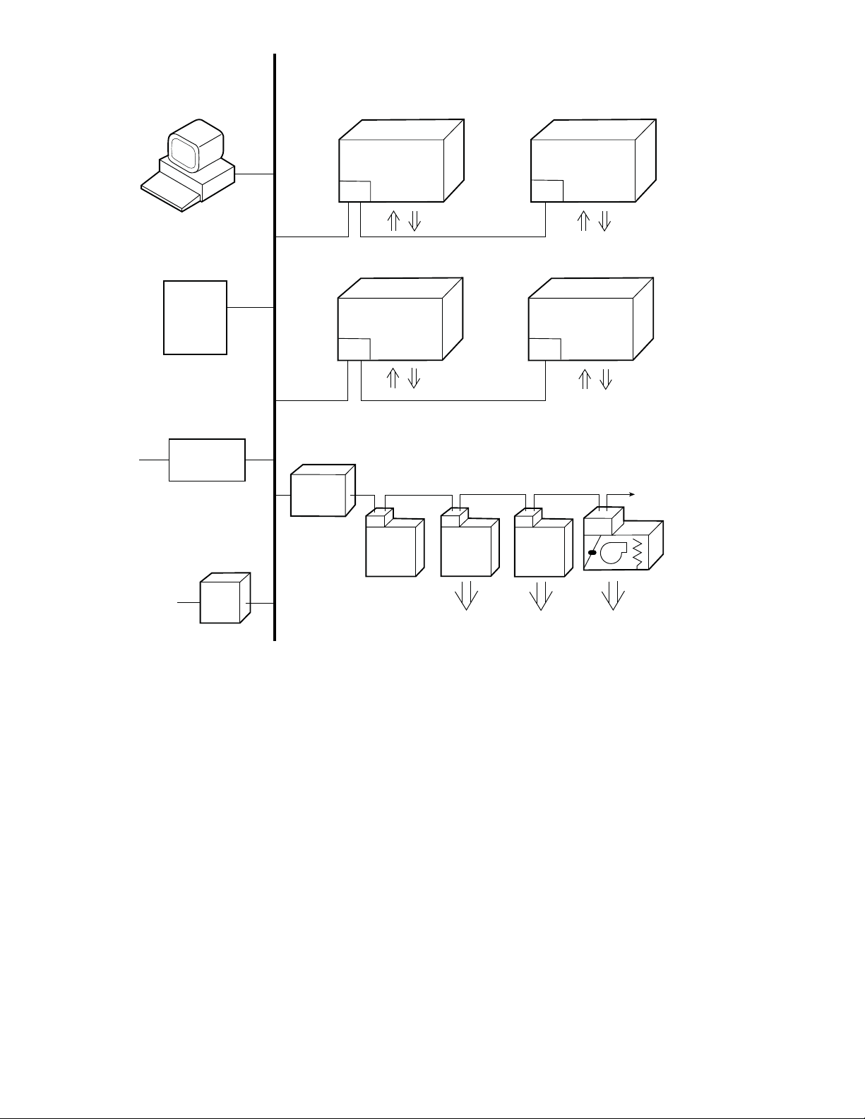
CCN BUS
BUILDING SUPERVISOR
REMOTE
CCN SITE
NETWORK
OPTIONS
AUTODIAL
GATEWAY
TERMINAL
SYSTEM
MANAGER
CL
CL
ROOFTOP
UNIT
ROOFTOP
UNIT
CL
ROOFTOP
UNIT
HEATING/COOLING UNITS
TCU
DAV AI R
TERMINAL
TCU
DAV AIR
TERMINAL
CL
CL
ROOFTOP
UNIT
ROOFTOP
UNIT
TCU
CCN -- Carrier Comfort Network
LEGEND
CL -- ComfortLink Controls
DAV -- Digital Air Volume
HVAC -- Heating, Ventilation, and
Air Conditoning
TCU -- Terminal Control Unit
TO
ADDITIONAL
TERMINALS
DAV FAN
POWERED
MIXING
BOX
®
NON CARRIER
HVAC
EQUIPMENT
COMFORT
CONTROLLER
AIR DISTRIBUTION-DIGITAL AIR VOLUME CONTROL (DAV)
C07030
Fig. 39 -- CCN System Architecture
75
Page 76

APPENDIX A: SystemVut Controller Display
Run Status Main Menu Layout
Display Text Expanded Text Values Units Write Status Point
SHUTDOWN UNIT? Local Unit Shutdown Req. Ye s/N o n/a Command
RUN STATUS Run Status Menu
MODE Mode Stat us Menu
MODE Opera ting Mode see Appendix B MODETEXT
S U B --- M O D E O p e r a t i n g Su b --- M o d e see Appendix B SUBMTEXT
DEMAND System Demand see Appendix B SYS_ DMDT
LINKAGE ACTIVE Linkage Active Yes /N o Forcible LNK_ACT
EFF COOL SETPOINT Cool Setpoint In Effect xx.x °F CSP_EFF
EFF HEAT SETPOINT Heat Setpoint In Effect xx.x °F HSP_EFF
DEMAND CTRL TEMP Effective Demand Temp xxx.x °F TEMP_ EFF
OCC SPRH SET PT Occupied SPRH Setpoint 0 to 100 % SPRH_OSP
UNOCC SPRH SET PT Unoccupied SPRH Setpo int 0 to 100 % SPRH_USP
COOL MODE T.GUARD Cool Mode Select T.guard xxx sec COOLMSTG
HEAT MODE T.GUARD Heat Mode Select T.guard xxx sec HEATMSTG
COOLING DEMAND Space Cooling Demand xx.x °F COOL_DMD
COOL DEMAND TREND Cooling Demand Trend xx.x ^F/min CLDTREND
HEATING DEMAND Heating Space Demand xx.x °F HEAT_DMD
HEAT DEMAND TREND Heat Space Demand Trend xx.x ^F/min HTDTREND
DMD LIMIT STATUS DEMAND LIMIT STATUS
COOL DMD LIM OFF Cool Demand Limiting Off/On CDMLMOFF
HEAT DMD LIM OFF Heat Demand Limiting Off/On HDMLMOFF
COOL DMD LIM LEV Cool demand Limit Level 0to3 CDMDLLEV
HEAT DMD LIM LEV Heat demand Limit Level 0to3 HDMELLEV
CL DMD LIM OFFSET Cool Demand limit offset xx.x °F COOLDLMO
HT DMD LIM OFFSET Heat Demand limit offset xx.x °F HEATDLMO
COOL Cooling Status Menu
IDF SPEED OUTPUT Commanded IDF Speed 0 to 100 % FANS PEED
ACTIVE COOL STAGE Actual Cool Stage Active x ACTCSTGS
COMMANDED ODF SPD Commanded ODF Speed xxxx rpm ODFSPD
ODF SDT SP ODF Control SDT SP xxxx °F ODFSDTSP
LA CTRL STATUS Low Ambient Ctrl Status 0=Normal,
REQ. DEHUM LEVEL Requested Dehum Level 0to2 REQDHLEV
MECHANICAL COOLING Mechanical Cooling Detail Sub--- Menu
OK TO USE COMPS? Ok to use compressors? Yes / No OKMECHCL
MECH COOL ACTIVE Mechanical Cool active? Ye s/ No MECHCOOL
MAX COOL STAGES Max Allowed Cool Stages 0to3 Forcible MAXCSTGS
REQ. COOL STAGES Requested Cooling Stages 0to3 REQCSTGS
ACTIVE COOL STAGE Actual Cool Stage Active x ACTCSTGS
COMMANDED ODF SPD Commanded ODF Speed xxxx rpm ODFSPD
COMP A1 TIMEGUARD Compressor A1 Timeguard xxx sec TIMGD_ A1
COMP A2 TIMEGUARD Compressor A2 Timeguard xxx sec TIMGD_ A2
SUPPLY AIR TREND Supply Air Temp Trend xxx.x ^F/min SATTREND
COMP A1 STRIKES Compressor A1 Strikes x A1STRIKE
COMP A2 STRIKES Compressor A2 Strikes x A2STRIKE
HI PRESS OVERRIDE High Pressure Override Yes/N o HP_OVR
CIRCUIT A LOCKOUT Circuit A Locked Out Ye s/ No CIRALOCK
LOW COOL LOCKOUT Low cooling locked out Yes/ No LC_LOCK
MED COOL LOCKOUT Medium Cooling lockout Yes /N o MC_LOCK
COMP A1 AVAILABLE Compressor A1 Available Yes/N o CA1_AVAL
COMP A1 LOCKOUT Compressor A1 locked out Yes / No CA1_LOCK
COMP A2 AVAILABLE Compressor A2 Available Yes/N o CA2_AVAL
COMP A2 LOCKOUT Compressor A2 locked out Yes / No CA2_LOCK
FREE COOLING Free Cooling Detail Sub --- menu
OK TO FREE COOL? OKtoUseFreeCooling? Yes /N o OKFREECL
IN FREE COOLING Free Cooling a ctive Ye s/ No FREECOOL
FREECOOL SAT SP Free Cooling SAT Setpnt xx.x °F FC_SATSP
REQ. DAMPER POS Requested Damper Pos 0 to 100 % REQDAMP
ECON OPERATIONAL? Econ Damper Operational Yes /N o DAMPGOOD
DRY BULB LOCKOUT Dry Bulb Lockout Yes/ No Forcible DBLOCK
ENTHALPY LOCKOUT Enthalpy Lockout Yes/ No Forcible ENTHLOCK
OK TO UNOCC FC? Ok to unocc Free Cool? Ye s/N o OKTOUFC
IN UNOC FREECOOL? Unocc Free Cool Active Ye s/N o UFC_ACT
UFC LOCKOUT? Unocc Free Cool Lockout Ye s /N o UNOCLOCK
1=Entering,
2=LowAmbient,
3 = Exiting
LACTRLST
76
Page 77
APPENDIX A: SystemVut Controller Display
Run Status Main Menu Layout (cont)
Display Text Expanded Text Values Units Write Status Point
COOL (cont) Cooling Status Menu
DEHUM DEHUM
OK TO DEHUM Ok to Dehumidify? Ye s/N olo c ke d o ut OKTODHUM
OD TO FAN BASE DH Ok to fan base d dehum Ye s/ No OKTOFBD
HUMIDIMIZER OK Ok to use humidimizer Ye s /N o OKTOHUMZ
REQ. DEHUM STGS Req Compr DehumStgs 0to3 REQDSTGS
FBD SST LOCK OUT FBDH SST Yes/ No FBDSSTLO
FBD SAT LOCK OUT FBDH SAT Lockout Ye s/N o FBDSATLO
HEAT Heating Status Menu
IDF SPEED OUTPUT Commanded IDF Speed 0 to 100 % FANS PEED
IGC FAN REQUEST IGC Fan On Request (IFO) On/Off IGC_IFO
REQ. HEAT STAGES Requested Heating Stages 0to2 REQHSTGS
ACTIVE HEAT STAGE Actual Heat Stage Active x ACTHSTGS
OK TO USE HEAT? OK to Run Heat Ye s/N o OKTOHEAT
MAX HEAT STAGES Max Allowed Heat Stages 0to2 Forcible MAXHSTGS
HEAT 1 TIMEGUARD Heat Stage 1 Timeguard xxx sec TIMG D_H1
HEAT 2 TIMEGUARD Heat Stage 2 Timeguard xxx sec TIMG D_H2
SUPPLY AIR TREND Supply Air Temp Trend xxx.x ^F/min SATTREND
HEAT LOCKOUT All Heat Stages Lockout Ye s /N o Forcibl e ALLHTLOC
HEAT 1 AVAILABLE Heat Stage 1 Available Ye s/ No HT1_AVAL
HEAT 2 AVAILABLE Heat Stage 2 Available Ye s/ No HT2_AVAL
OK TO SA TEMPER OK to SupplyAirTempering Yes /No OKTOTEMP
VENTILATION Ventilation Status Menu
VENT MODE Ventilation Status see Appendix B VENT TEXT
EFFECTIVE MIN POS MinPositioninEffect 0 to 100 % Forcible MIN_POS
ECON ACT POSITION Econo Actual Position 0 to 100 % DAMPPOS
IDF SPEED OUTPUT Commanded IDF Speed 0 to 100 % FANS PEED
OCCUPIED NOW Currently Occupied Yes/ No Forcible OCCUPIED
IN PREOCC PURGE? In Pre --- Occupancy Purge? Yes / No PREOCCON
IN FREE COOLING Free Cooling active Yes /N o FREECOOL
DIFF AIR QUALITY Differential Air Quality xxxx PPM AQ_DIFF
OK TO PREOC PURGE Ok to Preoccupancy Purge Ye s/N o OKPREOCC
Override IAQ? Is IAQ Override Active? Ye s /N o enum IAQ_OVRD
IAQ OVRRD SW STAT IAQ o verride sw state Ye s /N o enum I A Q --- O V R S
DCV CURVE OFFSET IAQ DCV Curve Offset 0 to 100 % IAQ_OFFS
INDOOR FAN Indoor Fan Status Menu
IDF SPEED OUTPUT Commanded IDF Speed 0 to 100 % FANS PEED
IDF SPD OVERRIDE IDF Speed Override Flag On/Off enum FAN_OVRD
IDF ERRORS? IDF Operation Errors? Yes /No enum IDFBAD
IDF SPD REDUCTION IDF Speed Reduction On Ye s/N o enum FANR ED10
VFD OUTPUT AMPS IDF VFD Output Amps xxx.xx amps OUTMCUR
VFD OUTPUT HP IDF VFD Output Power hp xxxx.x HP OUTPWRHP
VFD FAULT DETAIL IDF VFD Fault Detail 0=NONE,
VFD WARN DETAIL IDF VFD Warning Detail 0=NONE,
GENERAL General Run Data Menu
FILTER TIME LEFT Filter hour remaining xxxx hours FILTLEFT
RESET FILTER TIME Reset Filter Timer Yes/ No n/a Command RESETFLT
IN DAYLIGHT SAVE? DST currently active Ye s/ N o n/a DST_ACTV
TCS ACTIVE? Temp Compensate Start On Ye s/ No n/a TCS_ACT
1=PWR CARD,
2=EARTH FLT,
3=CTRL WORD,
4=OVER CIRR,
5=OVERLOAD,
7=UNDERVOLT,
8=OVER VOLT
9=SHORT CIR,
10=PHASELOSS,
11=U LOSS,
12=V LOSS,
13=W LOSS,
14=CTRL VOLT,
15=VDD LOW,
16=MULTIPLE,
17=UNEXPECT
1=VOLTAGE,
2=CURRENT,
3=THERMAL,
4=MULTIPLE,
5=UNEXPECT
SVFDFL
SVFDWAR
77
Page 78
APPENDIX A: SystemVut Controller Display
Run Status Main Menu Layout (cont)
Display Text Expanded Text Range Units Default Point
OCCUPANCY OCCUPANCY DATA
OCCUPIED NOW Currently Occupied Ye s/N o Forcible OCCUPIED
MINS UNTIL OCC Mins until next occupied xxxxx min MINTILOC
ACTIVE OCC CTRL Active Occupancy control 0=24/7 OCC,
LINKAGE OCC REQ Linkage Occupied Request 0=Unocc,
TIMEDOVRDREMAIN Timed Override Remaining 0 to 240 min Fo rcible OVR_EXT
REMOTE OCC SWITCH Remote Occupancy Switch On/Off Forcible REMOCC
BMS OCC REQUEST BMS Occupancy Re quest 0=UNOCC,
LOCAL OCC REQUEST Local Sched Occ Request 0=Unocc,
ACTIVE PERIOD Active Schedule period 0to8 PER_NO
HOLIDAY TOMORROW? Tomorrow Is A Holiday Ye s/ No HOL_TMRW
HOLIDAY TODAY? Today Is A Holiday Yes /N o HOLTODAY
NEXT OCC DAY Next Occupied Day DDD NXTOCDAY
NEXT OCC TIME Next Occupied Time hh:mm NXTOCTIM
NEXT UNOCC DAY Next Unoccupied Day DDD NXTUNDAY
NEXT UNOCC TIME Next Unoccupied Time hh:mm NXTUNTIM
PREV UNOCC DAY Previous Unccupied Day DDD PRVUNDAY
PREV UNOCC TIME Previous Unoccupied Time hh:mm PRVUNTIM
1=SCHEDULE,
2=BAS CTRL,
3=REMOC CTL,
4=TIME OVRD,
5=LINKAGE,
6=FORCED
1=Occupied,
2=Disabled
1=OCCUPIED,
2=DISABLED
1=Occupied
Forcible BMS_OCC
Forcible LOC_O CC
OCC_CTRL
LNK_OCC
Settings Main Menu Layout
Display Text Expanded Text Range Units Default Point
SETTINGS Settings Menu
SPACE SET POINTS Space Setpoints Adjustment Menu
OCC COOL SETPOINT Occupied Cool Setpoint 55 t o 80 °F 78 OCSP
OCC HEAT SETPOINT Occupied Heat Setpoint 55 to 80 °F 68 OHSP
UNOCC COOL SETPNT Unoccupied Cool Setpoint 65 to 95 °F 85 UCSP
UNOCC HEAT SETPNT Unoccupied Heat Setpoint 40 to 80 °F 60 UHSP
H E A T --- C O O L S P GA P Heat--- Cool Setpoint Gap 2to10 ^F 5 HCSP_GAP
SPT SLIDER RANGE SPT Offset Range (+/--- ) 0to5.0 °F 5 SPTO_RNG
OCC SPRH SET PT Occupied SPRH Setpo int 0 to 100 % 55 SPRH_OSP
UNOCC SPRH SET PT Unoccupied SPRH Setpoint 0 to 100 % 55 SPRH_USP
SA TEMPER SET PNT SA tempering Set point xx °F 50 SATEMPSP
TEMP DEMAND CONFIG Temperature Demand Configuration menu
LOW COOL DMD ON Low Cool Demand On --- 1 t o 2 . 0 °F 0.5 DMDLCON
MEDCOOLDMDON Medium Cool Demand On 0.5 to 20.0 °F 1 DMDMCON
HIGH COOL DMD ON High Cool Demand On 0.5 to 20.0 °F 2 DMDHCON
LOW COOL DMD OFF Low Cool Demand Off --- 1 t o 2 . 0 °F --- 0 . 5 DMDLCOFF
COOL DMD LEVEL UP Cool Demand Level Up --- 2 t o 2 . 0 ^F/min --- 0 . 2 CDMD_LUP
LOW HEAT DM D O N Low Heat Demand On --- 1 to 2 . 0 °F 0.5 DMDLHON
HIGH HEAT DMD ON High Heat Demand On 0.5 to 20.0 °F 2 DMDHHON
LOW HEAT DM D O FF Low Heat Demand Off --- 1 to 2 . 0 °F --- 0 . 5 DMDLHOFF
HEAT DMD LEVEL UP Heat Demand Level Up --- 2 to 2 . 0 ^F/min --- 0 . 2 HDMD_LUP
DEMAND TIMEGUARD1 Space Demand Time Guard1 60 to 600 sec 180 TDMD_TG1
DEMAND TIMEGUARD2 Space Demand Time Guard2 0 to 600 sec 300 TDMD_TG2
DEMAND TIMEGUARD3 Space Demand Time Guard3 5 to 120 min 10 TDMD_TG 3
DMD LIMIT CONFIG DEMAND LIMIT CONFIG
COOL DMD LIM LEV1 Cool DMD Offset level 1 0t099 °F 1 CLDOLEV1
COOL DMD LIM LEV2 Cool DMD Offset level 2 0t099 °F 3 CLDOLEV2
COOL DMD LIM LEV3 Cool DMD Offset level 3 0t099 °F 5 CLDOLEV3
HEAT DMD LIM LEV1 Heat DMD Offset level 1 0t099 °F 1 HTDOLEV1
HEAT DMD LIM LEV2 Heat DMD Offset level 2 0t099 °F 3 HTDOLEV2
HEAT DMD LIM LEV3 Heat DMD Offset level 3 0t099 °F 5 HTDOLEV3
CLOCK Clock Adjustment Menu
TIME Clock Hour and Minute xx:xx hh.mm TIME
DATE Current Date MM/DD/YYYY DATE
DAYLIGHT SAVINGS Daylight Savings Configuration Menu DST Menu
DAYLIGHT SAVINGS? DST allowed? Enable/Disable Enable DST_CFG
78
Page 79

APPENDIX A: SystemVut Controller Display
Settings Main Menu Layout (cont)
Display Text Expanded Text Range Units Default Point
CLOCK (cont) Clock Adjustment Menu
DST START MONTH DST Start Month 1=JANUARY,
DST START WEEK DST Start Week 1to5 2 STARTW
DST START DAY DST Start Day 1=MONDAY,
DST MINS TO ADD DST Minutes to Add 0to90 min 60 MINADD
DST STOP MONTH DST Stop Month 1=JANUARY,
DST STOP WEEK DST Stop Week 1to5 1 STOPW
DST STOP DAY DST Stop Day 1=MONDAY,
DST MINS TO SUB DST Minutes to Subt ract 0to90 min 60 MINSUB
START TIME IN DAY Time in day to start DST 0 to 600 min 120 DST_TOD
SCHEDULES Schedules Adjustment Menu
SCHEDULE NUMBER CCN Schedule Number 0 = Always Occupied,
OCCUPANCY SCHEDULE OCCUPANCY SCHEDULE DATA
HOLIDAYS Holiday adjustment Menu
ALLOW G. HOLIDAY? Accept Global Holidays? Ye s/ No No HOLIDAYT
TIMED OVR LENGTH Timed Override Duration 0to4 hours 4 OTL_CFG
UNIT CONFIGURATIONS Unit Configurations Menu
GENERAL General Unit Co nfigurations Menu
STARTUP DELAY Unit Startup Delay 10 to 600 sec 30 STARTDLY
UNIT CONTROL TYPE Unit Control Type 0=TSTAT,
THERMOSTAT TYPE Thermostat Hardware Type 0=CONV 2C2H,
ADAPTIVE TSTAT Tstat Adaptive Staging Ye s /N o Yes ADPTSTAT
DIRTY FILTER TIME Change Filter Timer 0 to 9999 hours 600 FILTLIFE
TEST MODE TIMEOUT Test inactivity time out 0=Disabled,
CCH MAX TEMP CCH Max Temperature 40 to 90 °F 65 CCHMAXT
STD BARO PRESSURE Std Barometric Pressure 13.00 to 35.00 in.Hg 29.92 STD_BARP
LINK STAGEUP TIME Linkage Stage inc. time 60 to 600 sec 180 LSTAGINC
UNIT’S MAX SAT Unit’s Maximum SAT 130 to 210 °F 200 UMAX_SAT
AUTO SAT FAULTS? Auto Clr SAT Limit Fault Ye s/N o No SATLACLR
ADAPTIVE TCS? Adaptive Temp Comp Start Enable/Disable Yes TCS_CFG
USER TCS BIASTIME User TCS Start bias time 0 to 180 min 0 TCSUBIAS
2=FEBRUARY,
3=MARCH,
4=APRIL,
5=MAY,
6=JUNE,
7=JULY,
8=AUGUST,
9=SEPTEMBER,
10=OCTOBER,
11=NOVEBER,
12=DECEMBER
2=TUESDAY,
3=WEDNESDAY,
4=THURSDAY,
5=FRIDAY,
6=SATURDAY,
7=SUNDAY
2=FEBRUARY,
3=MARCH,
4=APRIL,
5=MAY,
6=JUNE,
7=JULY,
8=AUGUST,
9=SEPTEMBER,
10=OCTOBER,
11=NOVEBER,
12=DECEMBER
2=TUESDAY,
3=WEDNESDAY,
4=THURSDAY,
5=FRIDAY,
6=SATURDAY,
7=SUNDAY
1 --- 6 4 = L o c a l Sc h e d u l e ,
65--- 99 = Global Schedule
1=SPACE SEN,
2=RAT SEN
1=DIGI 2C2H,
2=CONV 3C2H,
3=DIGI 3C2H
4=DIGI 2C2H_ S
1=30 minutes,
2=1 hour,
3=2 hours,
4=4 hours,
5=8 hours,
6=12 hours
3 STARTM
7 STARTD
1 STOPM
7 STOPD
0 SCHEDNUM
0=TSTAT CTRLTYPE
2=CONV 3C2H STATTYPE
4=4 hours TEST_ITO
79
Page 80
APPENDIX A: SystemVut Controller Display
Settings Main Menu Layout (cont)
Display Text Expanded Text Range Units Default Point
UNIT CONFIGURATIONS (cont) Unit Configurat ions Menu
SWITCH INPUTS CONFIGS DI Config Menu
FIRE SHUTDOWN SW Fire Shutdown Switch 0=NORM OPEN,
HUMSTAT CHANNEL HumidistatStatus Channel 0=None,
HUMSTAT SW TYPE Humidistat Switch Type 0=NORM OPEN,
FILTER SW CHANNEL Filter Status Sw Channel 0=None,
FILTER SW TYPE Filter Sta tus Swith Type 0=NORM OPEN,
REMOTE OCC CHAN Remote Occupancy Channel 0=None,
REMOTE OCC TYPE Remote Occupancy Sw Type 0=NORM OPEN,
REM.SHUTDOWN CHAN Remote Shutdown Channel 0=None,
REM.SHUTDOWN SW T Remote Shutdown Sw Type 0=NORM OPEN,
REM.SHUTDOWN TYPE Remot e Shutdown ALM Type 0=Normal,
COFS CHANNEL COFS Assigned Channel 0=None,
COFS TYPE COFS Switch Type 0=NORM OPEN,
GEN STATUS CHAN G eneral Status Channel 0=None,
GEN STAT SW TYPE General Status Sw Type 0=NORM OPEN,
SHUTDOWN GEN STAT General Status shutdo wn? Yes/N o Yes GENFATAL
ENTHALPY SW CHAN Enthalpy Sw Channel 0=None,
ENTHALPY SW TYPE Enthalpy Switch Type 0=NORM OPEN,
ANALOG INPUT CONFIGS Analog Inputs Configuration Menu
SPRH SENS CHANNEL SPRH Assigned Channel 0=None,
SPRH RH @ 4MA SPRH Sensor Value at 4mA 0 to 100 % 0 SPRH_4MA
SPRH RH @ 20MA SPRH Sensor Value @ 20mA 0 to 100 % 1 SPRH20MA
IAQ SENSOR CHAN IAQ Assigne d Channel 0=None,
IAQ PPM @ 4MA IAQ Sensor Value at 4mA 0 to 5000 ppm 0 IAQ_4MA
IAQ PPM @ 20MA IAQ Sensor Value at 20mA 0 to 5000 ppm 2000 IAQ_20MA
1=NORM CLSD,
2=NO SWITCH
1=MBB DI12,
2=MBB DI13.
3=MBB DI14,
4=MBB DI02,
5=MBB DI04,
6=SIOB Di01
1=NORM CLSD,
1=MBB DI12,
2=MBB DI13,
3=MBB DI14,
4=MBB DI02,
5=MBB DI04
1=NORM CLSD
1=MBB DI12,
2=MBB DI13,
3=MBB DI14,
4=MBB DI02,
5=MBB DI04
1=NORM CLSD
1=MBB DI12,
2=MBB DI13,
3=MBB DI14,
4=MBB DI02,
5=MBB DI04
1=NORM CLSD
1=Emergency
1=MBB DI12,
2=MBB DI13,
3=MBB DI14,
4=MBB DI02,
5=MBB DI04
1=NORM CLSD
1=MBB DI12,
2=MBB DI13,
3=MBB DI14,
4=MBB DI02,
5=MBB DI04
1=NORM CLSD
1=MBB DI12,
2=MBB DI13,
3=MBB DI14,
4=MBB DI02,
5=MBB DI04
1=NORM CLSD
1=MBB AI06,
2=MBB AI07,
3=MBB AI08
4=SIOB AI10
1=MBB AI06,
2=MBB AI07,
3=MBB AI08
2: no FIOP
0: FIOP
0=for all except
Humidimizer
6=Humidimizer Units
0=NORM OPEN HUMD_CFG
0=None FILTCHAN
0=NORM OPEN FILT_CFG
0=None RMOCCHAN
0=NORM OPEN RMOC_CFG
0=None ROFFCHAN
0=NORM OPEN ROFF_CFG
0=Normal ROFF TYPE
0=None COFSCHAN
1=NORM CLSD COFS_CFG
0=None GEN_CHAN
0=NORM OPEN GENS_CFG
0=None ENTHCHAN
0=NORM OPEN ENTH_CFG
0=None SPRHCHAN
0: no FIOP
1: FIOP
FIRE_CFG
HUMDCHAN
IAQ_CHAN
80
Page 81
APPENDIX A: SystemVut Controller Display
Settings Main Menu Layout (cont)
Display Text Expanded Text Range Units Default Point
ANALOG INPUT CONFIGS (cont) Analog Inputs Configura tion Menu
OAQ SENSOR CHAN OAQ Assigned Channel 0=None,
OAQ PPM @ 4MA OAQ Sensor Value at 4mA 0 to 5000 ppm 0 OAQ_4MA
OAQ PPM @ 20MA OAQ Sensor Value at 20mA 0 to 5000 ppm 2000 OAQ_20MA
OARH SENSOR CHAN OARH Assigned Cha nnel 0=None,
OARH RH @ 4MA OARH Sensor Value at 4mA 0 to 100 % 0 OARH_4MA
OARH RH @ 20MA OARH Sensor Val. at 20mA 0 to 100 % 100 OARH20MA
RARH SENS CHANNEL RARH Assigned Channel 0=None,
RARH RH @ 4MA RARH Sensor Value at 4mA 0 t o 100 % 0 RARH_4MA
RARH RH @ 20MA RARH Sensor Value @ 20mA 0 to 100 % 100 RARH20MA
OACFM SENSOR CHAN OACFM Assigned Channel 0=None,
OACFM @ 4MA OACFM value at 4mA 0 to 100 CFM 0 OCFM_4MA
OACFM @ 20MA OACFM Value @ 20mA 0 to 100 CFM 20 OCFM20MA
COOLING Cooling Configurations Menu
COOLING STAGE QTY Number of Cooling Stages 0to3 3 NUMCSTG S
LOW COOL COMP Low Cool Compressor 1to2 1 LC_COMP
COMP MIN ON TIME Compressor Min On Time 180 to 600 sec 300 C_MINON
COMP MIN OFF TIME Compressor Min Off Time 120 to 600 sec 180 C_MINOFF
STRIKE CLEAR TIME Runtime to Reset Strikes 120 to 999 sec 300 MIN_ON_ S
COOL STAGEUP TIME Cool Stage Increase Time 120 to 999 sec 450 CSTAGINC
COOL SATTREND LEV Cooling SAT Trend Level --- 1 . 0 t o 1 . 0 ^F/min --- 0 . 2 SAT_TLC
UPPER MIN SAT Cool Min SAT Upper Level 35.0 to 65.0 °F 56 (sizes 04 ---06)
LOWE R M IN SAT Cool Min SAT Lower Level 35.0 to 65.0 °F 46 (sizes 04 --- 06)
SPRH DEADBAND Space RH Deadband 0 % 5 SPRH_D8
HUMZ LOCKOUT OAT Humidimizer Lockout Temp --- 20 to 75 °F 40 OATLHUMZ
COOL FANOFF DELAY Cooling Fan--- off Delay 0 to 600 sec 75 COOL_FOD
FBD TYPE FBD CONTROL TYPE 0=None,
FBD SAT MIN VALUE FBD SAT MIN VALUE 35 to 80 °F 46 FBDH_SAT
FBD LOW SP FBD LOW SP --- 2 0 t o 0 °Fdelta --- 2 . 5 FBDLO_SP
FBD SST MIN VALUE FBD SST MIN VALUE 10 to 60 °F 32 FBDH_SST
LOW AMB IENT LOW AMBIENT CONFIGS MENU
CIR.A LOCKOUT OAT CircuitALockoutTemp --- 20 to 75 °F 0: no Economizer FIOP
LOW AMBIENT TEMP Low Ambient Temperature 0to80 °F 66 LA_TEMP
LOW COOL MIN OAT Low Cool lockout Temp --- 20 to 60 °F 10 (sizes 04 ---06)
MED COOL MIN OAT Medium Cool lockout Temp --- 20 to 60 °F 20 (sizes 07 --- 12)
LA DEHUM LEV 1 Low Ambient Dehum Le v 1 40 to 125 °F 80 LAHTEMP1
LA DEHUM LEV 2 Low Ambient Dehum Le v 2 40 to 125 °F 61 LAHTEMP2
LA DEHUM LEV 3 Low Ambient Dehum Le v 3 40 to 125 °F 55 LAHTEMP3
LA DEHUM SDT SP 1 LA Dehum SDT SP Lev 1 60 to 120 °F 82 LHSDTSP1
LA DEHUM SDT SP 2 LA Dehum SDT SP Lev 2 60 to 120 °F 93 LHSDTSP2
LA DEHUM SDT SP 3 LA Dehum SDT SP Lev 3 60 to 120 °F 104 LHSDTSP3
HUMZ ENABLE H umidimizer Status Ye s/ N o enum No for a ll except
RDVA ENABLE Re heat Dischg Valve CirA Yes/ No enum No for a ll exce pt
RLVA ENABLE Reheat Liquid Valve CirA Ye s/N o enum No for all except
CLVA ENABLE Cooling Liq Valve CirA Yes /N o enum No for all except
1=MBB AI06,
2=MBB AI07,
3=MBB AI08
1=MBB AI06,
2=MBB AI07,
3=MBB AI08
1=MBB AI06,
2=MBB AI07,
3=MBB AI08
1=MBB AI06,
2=MBB AI07,
3=MBB AI08,
4=SIOB AI10
1=Comfort,
2=Max
n/a 0: no Enthalpy FIOP
n/a 0=None RARHCHAN
n/a 0=None OCFMCHAN
0=None OAQ_CHAN
3: Enthalpy FIOP
53 (sizes 07 --- 12)
56 (sizes 14 --- 26)
42 (sizes 07 --- 12)
46 (sizes 14 --- 26)
0=None FBD_TYPE
40: Economizer FIOP
30 (sizes 07 --- 12)
40 (sizes 14 --- 26)
30 (sizes 14 --- 26)
Humidimizer units
Humidimizer units
Humidimizer units sizes
04--- 06
Humidimizer units sizes
04--- 06
OARHCHAN
SATMIN_H
SATMIN_L
OATLCMPA
LCLOCKSP
MCLOCKSP
HUMZ_EN
RDVA_EN
RLVA_EN
CLVA_EN
81
Page 82
APPENDIX A: SystemVut Controller Display
Settings Main Menu Layout (cont)
Display Text Expanded Text Range Units Default Point
COOLING (cont) Cooling Configurations Menu
LDVA ENABLE Liquid Divert Valve CirA Yes/N o enum No for all except
CHARGE DIAGNOSTICS Refrigerant Charge Diagnostic Config Menu
LOW CHARGE LEVEL Low Refrig Charge Level 0 to 150 psi 50 LOCHARG E
NO LOW CHARGE OAT Low Charge Disable Temp --- 40 to 50 °F 10 LOCH_LOT
CIR.A SDP LIMIT CirA High Pressure Limit 400 to 700 psig 600 HIPLIM_A
LOW DIS CH ARGE LEV Lo w Discharge Level 5.0 to 20.0 °F 7 SDTLEV
MIN PRES S RATIO Minimum pressure ratio 0.00 to 5.00 1.35 MINPSI_R
LOW SUC TIO N D IAG. Low Suct ion Diagnostic Config Menu
LOW SUC OK TEMP Suction OK Temperature 10.0 t o 50.0 °F 18 SSTOK
LOW SUC LEVEL 1 Low Suctio n Level 1 Temp 10.0 to 50.0 °F 20 SSTLEV1
LOW SUC LEVEL 2 Low Suctio n Level 2 Temp 5.0 to 50.0 °F 15 SSTLEV2
LOW SUC LEVEL 3 Low Suctio n Level 3 Temp 0.0 to 50.0 °F 10 SSTLEV3
LO SUC D IAG D ELAY Delay On Low SST Check 0 to 300 sec 0 SSTCKDLY
COMPRESSOR TRANSISTION
COMP L2 DIAG DLY Comp level 2 diag delay 1to99 sec 15 (sizes 04 --- 12)
IAG. COMP OFF Diag Comp Unexpected Off Enable/Disable Enable CD_UEOFF
CIR STUCK ON DIAG Circuit Stuck On Diag. Enable/Disable Enable DCKTOFF
CIR.A MIN DIS.P Min discharge change 0 to 99.0 psi 11 (sizes 04--- 12)
CIR.A MIN SUC.P Min Suction change 0 to 99.0 psi 4 ( s i z e s 0 4 --- 0 6 )
OFF P.RATIO CirA P.Ratio off change --- 1.00 to 1.00 --- 0.2 (sizes 07, 09 --- 14)
ODF SETTINGS Outdoor Fans Configurations Menu
ODF SIGNAL QTY Number of ODF Outputs 0to3 1 ( s i z e s 0 4 --- 0 6 )
ODF LOW COOL SPD ODF Low Cool Speed 0 to 1200 rpm 1000 (size 04)
ODF MED COOL SPD ODF Med Cool Speed 0 to 1200 rpm 1000 (size 04)
ODF HIGH COOL SPD ODF High Cool Speed 0 to 1200 rpm 1000 (size 04)
ODF MAXIMUM SPEED ODF Maximum Speed 0 to 1200 rpm 1000 (size 04)
ODF MINIMUM SPEED ODF Minimum Speed 0 to 1200 rpm 160 ODFMINSP
ODF ADVANCED CONFIGS Outdoor Fan Advanced Configs Menu
ODF GAIN ODF Gain --- 100 to 100.00 50 (sizes 04--- 06)
ODF ANTI --- WINDUP ODF anti--- windup factor ---100 to 100.00 0.6 ODF_NI
ODF INTEGRAL TIME ODF Integral Time --- 100 to 100.00 20 (sizes 04 ---12)
ODF MBIAS 1 ODF Map Bias Term 1 --- 200 to 200.00 72.5 (sizes 04--- 06)
ODF MBIAS 2 ODF Map Bias Term 2 --- 200 to 200.00 100.98 (sizes 04--- 06)
Compressor Transitio n diagnostic config menu
Humidimizer units sizes
07--- 26
40 (sizes 14 --- 26)
17 sizes 14 --- 26)
6.5 (size 07)
8 (size 08)
7 ( s i z e s 0 9 --- 1 2 )
14 (sizes 14 --- 26)
--- 0.3 (sizes 08, 17--- 26)
2 (sizes 07,17, or 20)
3 (sizes 08 --- 14, 24--- 26)
1075 (sizes 05 --- 06)
550 (sizes 07 --- 12)
700 (sizes 14 --- 17, 26)
650 (sizes 20 --- 24)
1075 (sizes 05 --- 06)
700 (sizes 07, 12, or 24)
600 (size 08)
650 (size 09)
800 (sizes 14,17, or 26)
750 (size 20)
1075 (sizes 05 --- 06)
950 (sizes 07 or 09)
900 (size 08)
1000 (sizes 12 --- 26)
1075 (sizes 05 --- 06)
950 (sizes 07 or 09)
900 (size 08)
1000 (sizes 12 --- 26)
1 (size 07)
2 ( s i z e s 0 8 --- 1 2 )
1.8 (sizes 14 ---20)
1.4 (sizes 24 ---26)
40 (sizes14---26)
66.7 (size 07)
--- 44.55 (sizes 08 --- 12)
10 (sizes 14 --- 20)
72.5 (sizes 24 ---26)
95.2 (size 07)
80.59 (sizes 08 --- 12)
35.3 (sizes 14 ---20)
100.98 (sizes 24 --- 26)
LDVA_EN
CDDTLEV2
MDP_DISA
MDP_SUCA
OFFPR_A
NUM_ODF
ODFLCSPD
ODFMCSPD
ODFHCSPD
ODFMAXSP
ODF_KC
ODF_TI
ODFBIAS1
ODFBIAS2
82
Page 83

APPENDIX A: SystemVut Controller Display
Settings Main Menu Layout (cont)
Display Text Expanded Text Range Units Default Point
ODF SETTINGS (cont) Outdoor Fans Configurations Menu
ODF MBIAS 3 ODF Map Bias Term 3 --- 200 to 200.00 20.93 (sizes 04--- 06)
ODF SWITCH POINT1 ODF Fan Switch Point 1 --- 100 to 100.00 3.68 (size 07)
ODF SWITCH POINT2 ODF Fan Switch Point 2 --- 100 to 100.00 17.1 (size 07)
ODF SWITCH POINT3 ODF Fans Switch Point 3 ---100 to 100.00 100 (sizes 07, 14--- 20)
ODF PROP PR ODF Proportional ctrl Pr --- 100 to 100.00 1.4 (sizes 04 --- 06)
ODF MSLOPE 1 ODF Map Slope Term 1 --- 100 to 100.00 55.3 (sizes 04--- 06)
ODF MSLOPE 2 ODF Map Slope Term 2 --- 100 to 100.00 19.07 (sizes 04--- 06)
ODF MSLOPE 3 ODF Map Slope Term 3 --- 100 to 100.00 8.85 (sizes 04--- 06)
HEATING Heating Configurations Menu
UNIT TYPE OF HEAT Type of Heat Installed 0=ELECTRIC,1=GAS 0(50series)
HEATING STAGE QTY Number of Heating Stages 0to2 2 (all except below);
HEAT MIN ON Heat Minimum On Time 60 to 600 sec 120 H_MINON
HEAT MIN OFF Heat Minimum Off Time 60 to 600 sec 120 H_MINOFF
HEAT STAGEUP TIME Heat Stage Increase Time 120 to 999 sec 450 HSTAGINC
HEAT SATTREND LEV Heating SAT Trend Level --- 1 t o 1 . 0 ^F/min 0.2 SAT_TLH
LOWE R M AX S AT Heat Max SAT Lower Level 85.0 to 200.0 °F 140 SATMAX_L
UPPER MAX SAT Heat Max SAT Upper Level 85.0 to 200.0 °F 160 SATMAX_H
HEAT FANOFF DELAY Heating Fan--- off Delay 10 to 600 sec 30 (50 series)
HEAT LOCKO UT OAT Heating Lockout Temp 40 to 125 °F 75 OATLHEAT
SAT DURING HEAT? SAT Heat Mode Sensing Enable/Disable Disable SAT_HEAT
IGC IFO TIMEOUT No IGC I FO input Timeout 0to60 min 5 NO_IGCTM
PREHEAT W/O IDF? Pre--- Heat HX without IDF? Enable/Disable Disable PREHT_HX
PREHEAT FAN DELAY Pre---HeatFanOnDelay 0 to 120 sec 30 PREHT_ TM
SA TEMPER ENABLED SupplyAirTemperingEnable Ye s /N o Yes SATEMPEN
SA TEMPER SET PNT SA tempering Set point xx °F 50 SATEMPSP
TEMPER MAX OUT Max OAT for SA tempering --- 40 to 125 °F 48 OATSTEMP
INDOOR FAN Indoor Fan Configurations Menu
OCCUPIED FAN? FanOnWhenOccupied Ye s /N o Yes FANON_O C
INDOOR FAN TYPE Indoor Fan Type 0=None
DIR DRV IDF SPDS Direct Drive Fan Speeds 2=2
SHUTDOWN IDF FAIL Shut Down on IDF Failure Ye s/N o enum No FATALFAN
IDF VFD VOLTAGE IDF VFD Nom. Motor Volts 50 to 100 volts See VFD Motor Defa ult
1=VFD
2=Direct Drive
3=3
1 1=Allunitsexceptsizes
2 2=fanoption0onsizes
0 (sizes 07, 14 --- 20)
65.29 (sizes 08 --- 12)
114.74 (sizes 24 --- 26)
3.4 (sizes 08 ---12)
4.84 (sizes 14 --- 20)
1.58 (sizes 24 --- 26)
9.06 (sizes 08 --- 12)
22.3 (sizes 14 ---20)
10.44 (sizes 24 --- 26)
19.76 (sizes 08 --- 12)
20.93 (sizes 24 --- 26)
25 (sizes 07 --- 12)
50 (sizes 14 --- 26)
25.3 (size 07)
60.09 (sizes 08 --- 12)
31 (sizes 14 --- 20)
55.33 (sizes 24 --- 26)
9 (size 07)
18.69 (sizes 08 --- 12)
9.6 (sizes 14 ---20)
19.07 (sizes 24 --- 26)
1 (sizes 07, 14 --- 20)
9.34 (sizes 08 --- 12)
8.85 (sizes 24 --- 26)
1(48series)
0(50serieswithout
FIOP heat),
1 (50 Series, sizes 04-- -06
low or medium heat),
1 (50 series, sizes
07--- 14 and low heat),
1 (50 series, sizes 07-- -12
and medium heat)
45 (48 series)
04---06 fan option “0”
2=fanoption0onsizes
04--- 06
04--- 06
Configuration Tables.
For sizes 04--- 06 see
Ta b l e 3 2 .
For size 07 --- 26 Vertical
units see Table 39 .
Fo r s i z e 07 --- 2 6 Ho r i z o nt al
units see Table 40 .
ODFBIAS3
ODFPIUP1
ODFPIUP2
ODFPIUP3
ODFPR_KC
ODFSLPE1
ODFSLPE2
ODFSLPE3
HEATTYPE
NUMHSTGS
HEAT_FOD
IDFTYPE
NUMFSPDS
MOTVOLT
83
Page 84
APPENDIX A: SystemVut Controller Display
Settings Main Menu Layout (cont)
Display Text Expanded Text Range Units Default Point
INDOOR FAN (cont) Indoor Fan Configurations Menu
IDF VFD NOM. FREQ IDF VFD Nom. Moto r Freq 20 to 400 hz 60 MOTRFEQ
IDF VFD NOM. AMPS IDF VFD Nom. Motor Amps 0.1 to 26.0 amps See VFD Mo tor Default
IDF VFD NOM. RPM IDF VFD Nom. Motor RPM 100 to 60000 rpm See VFD Motor Defa ult
IDF VFD MIN REF IDF VFD Min Reference 0 to 65.0 Hz 0 MINREF
IDF VFD MAX REF IDF VFD Max Reference 0 to 65.0 Hz 60 MAXREF
VFD ACCEL. TIME IDF VFD Accel. Time 1 to 1800 sec 10 RAMPUP_T
VFD DECEL. TIME IDF VFD Decel. Time 1 to 1800 sec 10 RAMPDN_T
IDF VFD AMP LIMIT IDF VFD Current Limit 0 to 300 100 CURRLMT
IDF VFD TIMEOUT IDF VFD Comm t ome out 1 to 600 sec 30 CNT_TOUT
IDF VFD RESET DUR IDF VFD Auto Reset time 0 to 600 sec 30 ARSTRT_T
VFD RFI FILTER IDF VFD RFI Filter On/Off On RFIFILTR
ECONOMIZER Eco nomizer Co nfigurations Menu
ECON INSTALLED? Economizer Installed? Ye s/N o No: no FIOP
ECON MAX POS Econ Max Damper Position 0 to 100 % 100 DAMPMAX
ECON TRAVEL TIME Economizer Travel Time 5 to 300 sec 150 ECONOTRV
MINIMUM POSITION CONFIGS Minimum Position Configurations menu
MIN POS @ MAX FAN Econ Min at Max Fanspeed 0 to 100 % 30 MINP_MAX
MIN POS SPEED 1 Min Pos --- User Speed 1 0 to 100 % 0 MP_USPD1
MIN POS DAMP 1 M i n P o s --- Us e r P o s 1 0 to 100 % 0 MP_UPOS1
MIN POS SPEED 2 Min Pos --- User Speed 2 0 to 100 % 0 MP_USPD2
MIN POS DAMP 2 M i n P o s --- Us e r P o s 2 0 to 100 % 0 MP_UPOS2
MIN POS SPEED 3 Min Pos --- User Speed 3 0 to 100 % 0 MP_USPD3
MIN POS DAMP 3 M i n P o s --- Us e r P o s 3 0 to 100 % 0 MP_UPOS3
FREE COOL CONFIGS Free Cooling Specific Configu r ation s Menu
LOW COOL SAT SP Low Free Cool SAT Setpnt 40 t o 80 °F 65 LCSASP
HIGH COOL SAT SP High FreeCool SAT Setpnt 40 to 80 °F 55 HC SASP
FREE COOL MAX OAT Free Cooling Max OAT 0to90 °F 65 MAXFREET
FREE COOL MIN OAT Free Cooling Min Temp --- 30 to 70 °F 0 MINFREET
DIFF DRY BULB CTL Diff. Dry Bulb Control Enable/Disable Disable DIFFBULB
DIFF DB DEADBAND Diff. Dry Bulb Deadband 0to20 °F 3 OATRATDB
ENTHALPY HI LIMIT Max Enthalpy OA limit 1.0 to 99.0 Btu/lb 28 FREEMAXE
DIFF ENTHALPY CTL Diff. Enthalpy Control Enable/Disable Disable DIFFENTH
ENTHALPY DEADBAND Enthalpy Cross Deadband 0 to 20.0 Btu/lb 2 OAERAEDB
E C O N O P I D --- KP Economizer PID --- kP 0.00 to 99.90 2.5 ECONO_P
E C O N O P I D --- KI Economizer PID --- kI 0.00 to 99.90 0.12 ECONO_I
E C O N O P I D --- KD Economizer PID --- kD 0.00 to 99.90 1 ECONO_D
E C O N O P I D --- R A T E Economizer PID --- rate 10 to 180 sec 15 ECONO_DT
UNOCCUPIED FREE COOL Unoccupied Free Cooling Configs Menu
WHEN TO UNOCC FC When to Unocc Free Cool? 0=Disabled,
UFCPREOCCTIME UFC PreOcc Time 1 to 999 min 120 UFCTIME
UFC LOW TEMP Unocc Free Cool Low Temp --- 30 to 70 °F 50 OATLUFC
POWER EXHAUST CONFIGS Power Exhaust Configurations Menu
PE1 RELAY CHANNEL PE1 Relay Channel 0=NONE,
PE1 POS @ MAX SPD PE Stage 1 at Max speed 0 to 100 % 40 PE1_PMAX
PE OFF DEADBAND PE Turn Off Dead band 0 to 100 % 5 PE_OFFDB
PE2 RELAY CHANNEL PE2 Relay Channel 0=NONE,
PE2 POS @ MAX SPD PE Stage 2 at max speed 0 to 100 % 75 PE2_PMAX
ECON DISCONNECT
DIAGNOSTIC
M D D --- H / C EN D DLY T24 Heat/Cool End Delay 0to60 min 25 T24CHDLY
Econ Actuator Mechanical disconnect
diagnostic menu
1=PreOcc,
2=Unocc
1=MBB RLY11,
2=MBB RLY06
1=MBB RLY11,
2=MBB RLY06
Configuration Tables.
For sizes 04--- 06 see
Ta b l e 3 2 .
For size 07 --- 26 Vertical
units see Table 39 .
Fo r s i z e 07 --- 2 6 Ho r i z o nt al
units see Table 40 .
Configuration Tables.
For sizes 04--- 06 see
Ta b l e 3 2 .
For size 07 --- 26 Vertical
units see Table 39 .
Fo r s i z e 07 --- 2 6 Ho r i z o nt al
units see Table 40 .
Yes : FIO P
1=PreOcc UFC_CFG
0: no FIOP
2: FIOP
0=None PE2_CHAN
MOTNOMSP
ECONO
PE1_CHAN
84
Page 85

APPENDIX A: SystemVut Controller Display
Settings Main Menu Layout (cont)
Display Text Expanded Text Range Units Default Point
ECONOMIZER (cont) Economizer Configurations Menu
MDD--- MIN MOVE T24Econ Min Move for SAT 10 to 20 % 10 T24ECSTS
M D D --- S AT D B Damper SAT deadband 0 to 20.0 °F 12 T24SATDB
M D D --- M I N R AT --- O A T T24 Min Diff in RAT--- OAT 5.0 to 20.0 °F 15 T24RATDF
MDD--- MIN TEST POS T24 Test Minimum Pos 0 to 100 % 15 T24TSTMN
MDD--- MAX TEST POS T24 Test Maximum Pos 0 to 100 % 85 T24TSTMX
AIR QUALITY Air Quality Configurations Menu
ANALOG IAQ CTRL Analog Input IAQ Control 0=NO IAQ,
IAQ POS @ MAX SPD IAQ Position at Max Fan 0 to 100 % 10 IAQMINP
LOW AIR .Q DI FF AQ Differential Low 0 to 5000 ppm 100 DAQ_LOW
HIGH AIR.Q DIFF AQ Differential High 0 to 5000 ppm 700 DAQ_HIGH
PREOCC PURGE ENBL IAQ Preoccupancy Purge Yes/N o Yes IAQPURGE
PURGE POS @ MAX IAQ Purge Pos at Max IDF 0 to 100 % 40 IAQPMAX
PREOCC LOW LIMIT Preocc Purge Lockout OAT 0to70 °F 50 IAQP_LA
PREOCC PURGE TIME Preocc Purge Duration 5 to 120 min 15 IAQPTIME
A Q D I F HI --- I A Q O V R AQ Diff High IAQOVERRIDE 0 to 5000 PPM 700 AQD_HIGH
A Q D I F LO --- I A Q O V R AQ Diff Low --- IAQ OVERRIDE 0 to 5000 PPM 100 AQD_LOW
IAQ OVRRD ENABLE IAQ override enable Yes / No enum No IAQOVREN
ALARM RELAY Alarm Relay Configurations Menu
ALM RELAY CHANNEL ALM Relay Assigned Chan 0=NONE,
THERMOSTAT ALERTS Thermostat Alerts Yes /N o Yes TSTAT_AL
HARDWARE ALERTS Hardware failures Alerts Ye s /N o Yes HW_AL
SAT/RAT ALERTS SAT/RAT Sensor Alerts Yes/ No Yes SATRAT AL
OAT SENSOR ALERTS OAT Thermistor Alerts Ye s /N o Yes OATRL_AL
SPACE SENS ALERTS Space Sensors Alerts Yes/ No Yes SP ACE_AL
TRANSDUCER ALERTS Transducer Sensor Alerts Yes/ No Yes TRANS_AL
RH SENSOR ALERTS RH sensor failure Alert Yes /N o Yes RHS_AL
CO2 SENSOR ALERTS Air Quality CO2 Alerts Yes/ No Yes CO2S_AL
OACFM SENS ALERTS OACFM Alarm Relay Yes /N o Yes OACFM_AL
ECONOMIZER ALERTS Economizer Alerts Ye s /N o Yes ECON_AL
AIRFILTERALERTS Dirty Filter Alerts Yes /N o Yes FILT_AL
GEN STATUS ALERTS General Status Alerts Yes/N o Yes GENS_AL
REFRIG CIR ALERTS Refrig Circuit Alerts Yes /No Yes CKT_AL
COMPRESSOR ALERTS Compressor Alerts Ye s/ No Yes COMP_AL
HEATING ALERTS Heating failure Alerts Yes/N o Yes HEAT_AL
INDOOR FAN ALERTS Indoor Fan Alerts Ye s/ No Ye s FAN_ AL
VFD ALERTS VFD Alerts Ye s/N o Yes VFD_AL
IO BOARD ALERTS Relay On Active IOBA Ye s/ No No IOBFA_AL
ON ACTIVE FAULTS Relay on Active Faults Ye s/ N o Yes FAULT_AL
NEW HARDWARE Quick Menu for New Hardware
UNIT CONTROL TYPE Unit Control Type 0=TSTAT,
ECON INSTALLED? Economizer Installed? Ye s/N o No: no FIOP
SPRH SENS CHANNEL SPRH Assigned Channel 0=None,
IAQ SENSOR CHAN IAQ Assigne d Channel 0=None,
OAQ SENSOR CHAN OAQ Assigned Channel 0=None,
OARH SENSOR CHAN OARH Assigned Cha nnel 0=None,
RARH SENS CHANNEL RARH Assigned Channel 0=None,
1=DCV,
2=IAQ OVRD,
3=CTRL MINP
1=MBB RLY11,
2=MBB RLY06
1=SPACE SEN,
2=RAT SEN
1=MBB AI06,
2=MBB AI07,
3=MBB AI08,
4=SIOB Ai10
1=MBB AI06,
2=MBB AI07,
3=MBB AI08
1=MBB AI06,
2=MBB AI07,
3=MBB AI08
1=MBB AI06,
2=MBB AI07,
3=MBB AI08
1=MBB AI06,
2=MBB AI07,
3=MBB AI08
0: no FIOP
1: FIOP
1=MBB RLY11 ALM_CHAN
0=TSTAT CTRLTYPE
Yes : FIO P
0=None SPRHCHAN
1: no FIOP
0: FIOP
0=None OAQ_CHAN
3: no FIOP
0: FIOP
0=None RARHCHAN
IAQANCFG
ECONO
IAQ_CHAN
OARHCHAN
85
Page 86

APPENDIX A: SystemVut Controller Display
Settings Main Menu Layout (cont)
Display Text Expanded Text Range Units Default Point
NEW HARDWARE (cont) Quick Menu for New Hardware
OACFM SENS CHANNEL OACFM Assigned Channel 0=None,
FIRE SHUTDOWN SW Fire Shutdown Switch 0=NORM OPEN,
FILTER SW CHANNEL Filter Status Sw Channel 0=None,
REMOTE OCC CHAN Remote Occupancy Channel 0=None,
REM.SHUTDOWN CHAN Remote Shutdown Channel 0=None,
COFS CHANNEL COFS Assigned Channel 0=None,
GEN STATUS CHAN G eneral Status Channel 0=None,
ENTHALPY SW CHAN Enthalpy Sw Channel 0=None,
SIOB1 INSTALLED SIOB 1 Enabled Yes /No No for all except
NETWORK SETTINGS Building Network Configurations Menu
BAS PROTOCOL BAS Protocol Select 0=NO NE,
NETWORK TIMEOUT Network Input Timeout 0 to 600 min 30 NETINTO
CCN CCN Network Configuration Menu
BUS NUMBER CCN Bus Number 0 to 239 0 CCNBUS
CCN ELEMENT # CCN Element Number 1 to 239 1 CCNADD
CCN BAUDRATE CCN Baud Rate 0=9600,
BROADCAST ACK? CCN Broadcast Ack’er Yes /N o No CCNBCACK
BROADCAST SCHEDL? Global Schedule Broadcst Yes /N o No CCN_GSBC
BROADCAST TIME? CCN Time Broadcast Yes/N o No CCNBC
BROADCAST OAT? Broadcast OAT On Network Ye s/N o No OATBC
BROADCAST OARH? Broadcast OARH On Netwrk Ye s/ No No OARHBC
BROADCAST OAQ? Broadcast OAQ On Network Ye s/N o No OAQBC
BROADCAST IAQ? Broadcast IAQ On Network Yes/ No No IAQBC
LOCATIO N Device Location text string <blank> DEV_LOC
REFERENCE NUMBER Reference number text string <blank> REF_NUM
BACNET BACnet network configuration menu
MAC ADDRESS BACnet Device Macaddress 1 to 127 01 BAC_MAC
BACNET BAUDRATE BACnet BMS baud rate 0=9600,
AUTO ID SCHEME ALC Auto Id Scheme Ye s/N o Yes AUID
BACNET AUTO ID BACnet ID Auto ID Yes / No Yes BAC_AUID
BACNET ID BACnet ID Number 0 to 4194302 1610101 BAC_ID
LINKAGE SET TINGS LINKAGE SETTINGS MENU
1=MBB AI06,
2=MBB AI07,
3=MBB AI08,
4=SIOB Ai10
1=NORM CLSD,
2=NO SWITCH
1=MBB DI12,
2=MBB DI13,
3=MBB DI14,
4=MBB DI02,
5=MBB DI04
1=MBB DI12,
2=MBB DI13,
3=MBB DI14,
4=MBB DI02,
5=MBB DI04
1=MBB DI12,
2=MBB DI13,
3=MBB DI14,
4=MBB DI02,
5=MBB DI04
1=MBB DI12,
2=MBB DI13,
3=MBB DI14,
4=MBB DI02,
5=MBB DI04
1=MBB DI12,
2=MBB DI13,
3=MBB DI14,
4=MBB DI02,
5=MBB DI04
1=MBB DI12,
2=MBB DI13,
3=MBB DI14,
4=MBB DI02,
5=MBB DI04
1=CCN,
2=BACNET
1=19200,
2=38400
1=19200,
2=38400,
3=57600,
4=76800,
5=115200
x 0=NONE BMS_CFG
0=None OCFMCHAN
2: no FIOP
0: FIOP
0=None FILTCHAN
0=None RMOCCHAN
0=None ROFFCHAN
0=None COFSCHAN
0=None GEN_CHAN
0=None ENTHCHAN
Humidimizer units
2=38400 BAUDENUM
4=76800 BAC_BAUD
FIRE_CFG
SIOB1_EN
86
Page 87
APPENDIX A: SystemVut Controller Display
Settings Main Menu Layout (cont)
Display Text Expanded Text Range Units Default Point
NETWORK SETTINGS (cont) Building Network Configurations Menu
DEVICE IAQ BACnet device for IAQ 0 to 4194303 1610100 DEVIAQ
OBJECT ID IAQ Object instance for IAQ 0 to 9999 1009 OBJIAQ
COV IAQ Change of value for IAQ 0to60 0 COVIAQ
DEVICE OAQ BACnet device for OAQ 0 to 4194303 1610100 DEVOAQ
OBJECT ID OAQ Object instance for OAQ 0 to 9999 285 OBJOAQ
COV OAQ Change of value for OAQ 0to60 0 COVOAQ
DEVICE OARH BACnet device for OARH 0 to 4194303 1610100 DEVOARH
OBJECT ID OARH Object instance for OARH 0 to 9999 1022 OBJOARH
COV OARH Change of value for OARH 0to60 0 COVOARH
DEVICE OAT BACnet device for OAT 0 to 4194303 1610100 DEVOAT
OBJECT ID OAT Object instance for OAT 0 t o 9999 1003 OBJOAT
COV OAT Change of value for OAT 0to60 0 COVOAT
DEVICE RARH BACnet device for RARH 0 to 4194303 1610100 DEVRARH
OBJECT ID RARH Object instance for RARH 0 to 9999 30 OBJRARH
COV RARH Change of value for RARH 0to60 0 COVRARH
DEVICE RAT BACnet device for RAT 0 to 4194303 1610100 DEVRAT
OBJECT ID RAT Object instance for RAT 0 to 9999 1010 OBJRAT
COV RAT Change of value for RAT 0to60 0 COVRAT
DEVICE SPT BACnet device for SPT 0 to 4194303 1610100 DEVSPT
OBJECT ID SPT Object instance for SPT 0 to 9999 2007 OBJSPT
COV SPT Change of value for SPT 0to60 0 COVSPT
LOCAL_SHEDL_ EDIT Allow Local Sched Edit Yes /N o enum No LCL_EDIT
SYSTEM TOUCH System Touch Menu
DEVICE INSTANCE System Touch Device Inst 0 to 4194303 160099 DEVST
POLLING RATE System Touch Poll Rate 10 to 60 10 POLLST
SPACE TEMP AI Sy stem Touch AI for SPT 0 to 9999 1 AISTSPT
SPACE RH AI System Touch AI for SPRH 0 t o 9999 4 AISTSPRH
ZS SENSOR CFG ZS Sensor Configuration
ZS1 ADDRESS Zo ne Sensor 1 Address 0 to 255 255 ZSADDR1
ZS2 ADDRESS Zo ne Sensor 2 Address 0 to 255 255 ZSADDR2
ZS3 ADDRESS Zo ne sensor 3 address 0 t o 255 255 ZSADDR3
ZS4 ADDRESS Zo ne sensor 4 address 0 t o 255 255 ZSADDR4
ZS5 ADDRESS Zo ne sensor 5 address 0 t o 255 255 ZSADDR5
ZS POLL RATE Zone sensor poll rate 1 to 100 sec 5 ZSPOLLRT
ZS UNIT Zone sensor unit 0=degrees F 0=degrees F ZSUNIT
ZSFRCUNOCENBL ZS Force Unoccup enable No No ZSFUNEN
ZSFRCUNOCDELAY ZS Force unocc wt delay No No ZSFUNWT
ZS TLO CONT ENBL ZS TLO Cont Enable No No ZSTLOEN
TLO SET DURING OC ZS TLO set during occ No No ZSTLSOC
ZS UI MODE Zone senso r UI Mode 1=Dual Offsets 1=Dual Offsets ZSUIM
NETWORK CHKLIST NETWORK SETUP CHECKLIST 0=Undone,
DISPLAY SETTINGS User Display Configurations Menu
METRIC DISPLAY Metric Display Yes /N o No DISPUNIT
LANGUAGE Display Language Select 0=English 0=English LANGUAGE
CONTRAST ADJUST LCD Contrast Adjustment 1to10 5 LCD_ CONT
PAS SW ORD ENABL E? User Password Protectio n Enable/Disable Enable PASS_ EB L
VIEW USER PASSWORD View User Password Menu
CHANGE USER PASSWORD Change User Password Menu
QUICK SETUP CONFIG QUICK SETUP CONFIG MENU
TIME Clock Hour and Minute xx:xx hh.mm 0 TIME
DATE Current Date MM/DD/YYYY 0 DATE
STARTUP DELAY Unit Startup Delay 10 to 600 sec 30 STARTDLY
UNIT CONTROL TYPE Unit Control Type 0=TSTAT,
THERMOSTAT TYPE Thermostat Hardware Type 0=CONV 2C2H,
DIRTY FILTER TIME Change Filter Timer 0 to 9999 hours 600 FILTLIFE
VENT IDF SPEED Ventilation Only IDF Spd 0 to 100 % 50 (sizes 04--- 06)
1=Perfom,
2=Done
1=SPACE SEN,
2=RAT SEN
1=DIGI 2C2H,
2=CONV 3C2H,
3=DIGI 3C2H
4=DIGI 2C2H
0=Undone CHK_NET
0=TSTAT CTRLTYPE
2=CONV 3C2H STATTYPE
67 (sizes 07 --- 12)
53 (sizes 14 or 20)
56 (size 17)
52 (size 24)
60 (size 26)
FSPDVENT
87
Page 88

APPENDIX A: SystemVut Controller Display
Settings Main Menu Layout (cont)
Display Text Expanded Text Range Units Default Point
QUICK SETUP CONFIG (cont) Building Network Configurations Menu
HEATING STAGE QTY Number o f Heating Stages 0to2 2 (all except below):
ECON INSTALLED? Economizer Installed? Ye s/ No No: no FIOP
FREE COOL MAX OAT Free Cooling Max OAT 0to90 °F 65 MAXFREET
FIRE SHUTDOWN SW Fire Shutdown Switch 0=NORM OPEN,
QUICK SET CHKLIST QUICK SETUP CHECKLIST 0=Undone,
1=NORM CLSD,
2=NO SWITCH
1=Perfom,
2=Done
0(50serieswithout
FIOP heat),
1 (50 series, sizes 04-- -06
low or medium heat),
1 (50 series, sizes
07--- 14 and low heat),
1 (50 series, sizes
07--- 12 and medium
heat)
Yes : FIO P
2: no FIOP
0: FIOP
0=Undone CHK_QUIK
Alerts/Faults Main Menu Layout
Display Text Expanded Text Values Write Status Point
ALERTS/FAULTS Alerts/Faults Menu
ACTIVE FAULTS Active Faults Menu
ACTIVE ALERTS Active Alerts Menu
HISTORY History Of Faults And Alerts Menu
RESET FAULT/ALERT Reset All Current Alarms Ye s/ No Command ALRESET
NUMHSTGS
ECONO
FIRE_CFG
88
Page 89
APPENDIX A: SystemVut Controller Display
Service Main Menu Layout
Display Text Expanded Text Values Units Write Status Point
SERVICE Service Menu
UNIT TESTS Unit Tests Menu
TEST MODE ServiceTestModeEnable On/Off Command
SERVICE TEST Service Test Menu
INDEPENDENTS INDEPENDENT TEST MENU
ECON POS TEST Economizer Position Test 0 to 100 % Command S_DAMPER
BUMP COMP A1 TEST Compressor Bump A1 Test On/Off On/Off Command S_BMPA1
BUMP COMP A2 TEST Compressor Bump A2 Test On/Off On/Off Command S_BMPA2
LIQ DIVERT A TEST LiqDivertrValveRelayTest On/Off On/Off Command S_ LDV_A
REHEAT A TEST ReheatDischgValveRelayT est On/Off On/Off Command S_RDV_A
R E H E A T L V --- A TE S T Reheat Liq Valv Rly Test On/Off On/Off Command S_RLV_A
COOLING LV--- A TEST Cooling Liq Valv Test On/Off On/Off Command S_CLV_A
CCH RELAY 1 TEST Crankcase Heater 1 test On/Off On/Off Command S_CCHR1
ALARM RELAY TEST Alarm Output Relay Test On/Off On/Off Command S_ALARM
PE1 RELAY TEST Po wer Exhaust 1 Test On/Off On/Off Command S_PE_ 1
PE2 RELAY TEST Po wer Exhaust 2 Test On/Off On/Off Command S_PE_ 2
FAN TESTS Indoor and Outdoor Fan tests Menu
IDF SPEED TEST Indoor Fan Speed Test 0 to 100 % Command S_IDFSPD
ALL ODF SPD TEST System ODF speed test 0 to 1200 rpm Command S_ODFSPD
ODF 1 SPEED TEST Outdoor Fan 1 speed test 0 to 1200 rpm Command S_ODF SP1
ODF 2 SPEED TEST Outdoor Fan 2 speed test 0 to 1200 rpm Command S_ODF SP2
ODF 3 SPEED TEST Outdoor Fan 3 speed test 0 to 1200 rpm Command S_ODF SP3
IDF MANUAL TRANS IDF Manual Transitio n Ye s/ No Command S_IDFTRN
ODF MANUAL TRANS ODF Manua l Transition Yes/N o Command S_ODF TRN
COOL TESTS Cooling Test Menu
COOL A1 TEST Cooling W/Comp.A1 Test On/Off Command S_COOLA1
COOL A2 TEST Cooling W/Comp.A2 Test On/Off Command S_COOLA2
IDF SPEED TEST Indoor Fan Speed Test 0 to 100 % Command S_IDFSPD
ALL ODF SPD TEST System ODF speed test 0 to 1200 rpm Command S_ODFSPD
HUMIDIMIZER TEST HumidiMizer Level 0=Off,
HEAT TESTS Heating Test Menu
HEAT 1 TEST Heating Stage 1 Test On/Off Command S_HEAT1
HEAT 2 TEST Heating Stage 2 Test On/Off Command S_HEAT2
IDF SPEED TEST Indoor Fan Speed Test 0 to 100 % Command S_IDFSPD
AUTOMATIC TEST Automatic Test Menu
AUTO INDP TEST AUTO INDEPENDENT TEST Ye s/ N o Command AUTOINDP
AUTO COOL TEST RUN AUTO COOLING TEST Yes /No Command AUTOCOOL
AUTO HEAT TEST RUN AUTO H EATING TEST Yes /No Command AUTOHEAT
AUTO SYSTEM TEST RUN AUTO SYSTEM TEST Yes/ No Command AUTOSYS
UNIT INFORMATION Unit Information Menu
MODEL # Equipment Model number xxxxxxxxxxxxxxxx Command EQ_ MOD
SERIAL # Equipment Serial number xxxxxxxxxx Command EQ_SER
ENTER MODEL NUMBER Edit Equipment Model Number
VERSIONS Versions Menu
SOFTWARE Application SW Version CESR131651---xx--- xx FW_CESR
VFD VFD1 SW Version FW VERSION--- x.xx VFD1_SW
IO BOARD SIOB1 SW Version SIOB1 SW VERSION - -- x.xx SIOB1_SW
BOOTLOADER Bootloader SW Version CESR131659--- xx--- xx BL_CESR
USER MEASURED DATA User Measured Data Menu
SUPPLY VOLTAGE L1 Supply Voltage Leg 1 0 to 700.0 volt Command L1VOLTS
SUPPLY VOLTAGE L2 Supply Voltage Leg 2 0 to 700.0 volt Command L2VOLTS
SUPPLY VOLTAGE L3 Supply Voltage Leg 3 0 to 700.0 volt Command L3VOLTS
COMP A1 AMPS L1 Comp A1 Amps Leg 1 0 to 100.0 amps Command CA1L1_A
COMP A1 AMPS L2 Comp A1 Amps Leg 2 0 to 100.0 amps Command CA1L2_A
COMP A1 AMPS L3 Comp A1 Amps Leg 3 0 to 100.0 amps Command CA1L3_A
COMP A2 AMPS L1 Comp A2 Amps Leg 1 0 to 100.0 amps Command CA2L1_A
COMP A2 AMPS L2 Comp A2 Amps Leg 2 0 to 100.0 amps Command CA2L2_A
COMP A2 AMPS L3 Comp A2 Amps Leg 3 0 to 100.0 amps Command CA2L3_A
E.HEAT AMPS L1 Elec. Heat Amps Leg 1 0 to 100.0 amps Command EHTL1_A
E.HEAT AMPS L2 Elec. Heat Amps Leg 2 0 to 100.0 amps Command EHTL2_A
E.HEAT AMPS L3 Elec. Heat Amps Leg 3 0 to 100.0 amps Command EHTL3_A
GAS SUPPLY TYPE Gas Supply Type 0=NATURAL,
GAS INLET PRESS Gas Inlet Pressure 0 to 20.0 in.wc Command GASPRESS
STAGE 1 GAS PRESS Stage 1 Gas Pressure 0 to 20.0 in.wc Command HT1PRESS
STAGE 2 GAS PRESS Stage 2 Gas Pressure 0 to 20.0 in.wc Command HT2PRESS
CONTINUE? Start Diag Report Yes /No Command GO_DIAG
1=Subcool,
2=Reheat
1=LP
Command S_HMZLEV
Command GASTYPE
89
Page 90
APPENDIX A: SystemVut Controller Display
Service Main Menu Layout (cont)
Display Text Expanded Text Values Units Write Status Point
RUN HOURS & CYCLES Run Hours & Cycles Menu
RUN HOURS DATA MENU Run hours menu
COMP A1 RUN HOURS Compressor A1 Run Hours xxxxxx.x hours HR_A1
COMP A2 RUN HOURS Compressor A2 Run Hours xxxxxx.x hours HR_A2
ALM RELAY HOURS Alarm Relay Run H ours xxxxxx.x hours HR_ALM
CCH RELAY HOURS CCH1 Relay Run Hours xxxxxx.x hours HR_CCHR1
ECON RUN HOURS Econ Damper Run Hours xxxxxx.x hours HR_DAMP
FULL LOAD HOURS Unit Full Load Run Hours xxxxxx.x hours HR_FLOAD
FREE COOL HOURS Free Cooling Run Hours xxxxxx.x hours HR_FREEC
HEAT 1 RUN HOURS Heat Stage 1 Run Hours xxxxxx.x hours HR_HTR_1
HEAT 2 RUN HOURS Heat Stage 2 Run Hours xxxxxx.x hours HR_HTR_2
IDF RUN HOURS Indoor Fan Run Hours xxxxxx.x hours HR_IDF
LDV_A RELAY HOURS LDV_A Run Ho urs xxxxxx.x hours HR_LDV_A
MAX IDF RUN HOURS Max Fan Speed Run Hours xxxxxx.x hours HR_MAXF
ODF1 OUTPUT HOURS ODF Spd Sig 1 Run Hours xxxxxx.x hours HR_ODF1
ODF2 OUTPUT HOURS ODF Spd Sig 2 Run Hours xxxxxx.x hours HR_ODF2
ODF3 OUTPUT HOURS ODF Spd Sig 3 Run Hours xxxxxx.x hours HR_ODF3
PE1 RELAY HOURS Power Exhaust1 Run Hours xxxxxx.x hours HR_PE_1
PE2 RELAY HOURS Power Exhaust2 Run Hours xxxxxx.x hours HR_PE_2
RDV_A RELAY HOURS RDV_ A Run Hours xxxxxx.x hours HR_RDV_A
SUBCOOLING HOURS Reheat level 1 Run Hrs xxxxxx.x hours HR_RQHL1
HOT GAS RH HOURS Reheat level 2 Run Hrs xxxxxx.x hours HR_RQHL2
TEST MODE HOURS Service Test Run Hours xxxxxx.x hours HR_STEST
VENT IDF H OURS Vent IDF Run Hours xxxxxx.x hours HR_VENTF
START COUNT DATA MENU Start Counts menu
COMP A1 STARTS Compressor A1 Starts xxxxxx ST_A1
COMP A2 STARTS Compressor A2 Starts xxxxxx ST_A2
ALM RELAY STARTS Alarm Relay Starts xxxxxx ST_ALM
ALM RESET COUNTS Alarm Reset Counts xxxxxx ST_ALRST
CCH RELAY STARTS CCH1 Relay Starts xxxxxx ST_CCH R1
DAMPER STARTS Economizer Damper Starts xxxxxx ST_DAMP
FULL LOAD STARTS Unit Full Load Starts xxxxxx ST_FLOAD
FREE COOL STARTS Free Cooling Starts xxxxxx ST_FREEC
HEAT 1 STARTS Heat Stage 1 Starts xxxxxx ST_HTR_1
HEAT 2 STARTS Heat Stage 2 Starts xxxxxx ST_HTR_2
IDF STARTS Indoor Fan Starts xxxxxx ST_ IDF
LDV A STARTS LDV_A Starts xxxxxx ST_LDV_A
MAX IDF SPD START Max IDF Speed St arts xxxxxx ST_MAXF
ODF OUT 1 STARTS ODF Spd Signal 1 Starts xxxxxx ST_ ODF1
ODF OUT 2 STARTS ODF Spd Signal 2 Starts xxxxxx ST_ ODF2
ODF OUT 3 STARTS ODF Spd Signal 3 Starts xxxxxx ST_ ODF3
RDV A STARTS RDV_A Starts xxxxxx ST_RDV_A
SUBCOOL STARTS Reheat level 1 Starts xxxxxx ST_RQHL1
HOT GAS RH STARTS Reheat level 2 Starts xxxxxx ST_RQHL2
PE1 RELAY STARTS Po wer Exh aust 1 S tarts xxxxxx ST_PE_1
PE2 RELAY STARTS Po wer Exh aust 2 S tarts xxxxxx ST_PE_2
POR COUNT Power Cycle Count s xxxxxx ST_POR
TEST MODE STARTS Service Test Starts xxxxxx ST_STEST
VENT FAN STARTS Ventilation Fan Starts xxxxxx ST_VENTF
RESET COUNTS MENU Reset Count s menu
COMP A1 RESET QTY Comp A1 Resets Count xxxxxx RS_A1
COMP A2 RESET QTY Comp A2 Resets Count xxxxxx RS_A2
ALMRLYRESETQTY Alarm Relay Resets Count xxxxxx RS_ALM
ALM RESET RESETS Alarm Reset Resets Count xxxxxx RS_ALRST
CCH RELAY RESETS CCH1 Relay Resets Count xxxxxx RS_CCHR1
DAMPER RESET QTY Econ Damper Resets Count xxxxxx RS_DAMP
FULL LOAD RESETS Full Load Resets Count xxxxxx RS_FLOAD
FREE COOL RESETS Free Cooling Reset Count xxxxxx RS_FREEC
HEAT 1 RESET QTY Heat Stage 1 Reset Count xxxxxx RS_HTR_1
HEAT 2 RESET QTY Heat Stage 2 Reset Count xxxxxx RS_HTR_2
IDF RESET QTY Indoor Fan Reset Count xxxxxx RS_IDF
LDV A RESET QTY xxxxxx RS_LDV_A
MAX IDF RESET QTY Max IDF Spd Resets Count xxxxxx RS_MAXF
ODF1 OUT RESETS ODF Signal1 Resets Count xxxxxx RS_ODF1
ODF2 OUT RESETS ODF Signal2 Resets Count xxxxxx RS_ODF2
90
Page 91

APPENDIX A: SystemVut Controller Display
Service Main Menu Layout (cont)
Display Text Expanded Text Values Units Write Status Point
RESET COUNTS MENU (cont) Reset Counts menu
ODF3 OUT RESETS ODF Signal3 Resets Count xxxxxx RS_ODF3
PE1 RESET QTY P.Exhaust 1 Resets Count xxxxxx RS_PE_1
PE2 RESET QTY P.Exhaust 2 Resets Count xxxxxx RS_PE_2
POR RESET QTY Power Cy cle Resets Count xxxxxx RS_POR
RDV A RESET QTY rdv_a Resets Count xxxxxx RS_RDV_A
SUBCOOL RESET QTY Reheat lev 1 Rst Count xxxxxx RS_RQHL1
HGRH RESET QTY Reheat le v 2 Rse Count xxxxxx RS_RQHL2
TEST MODE RESETS Service Test Reset Count xxxxxx RS_STEST
VENT IDF RESETS Vent IDF Resets Count xxxxxx RS_VENTF
POWER RESET HISTORY Power On Reset History Menu
POWRES00 Power Reset Event 00 mm/dd/yy, hh:mm:ss POWRES00
POWRES01 Power Reset Event 01 mm/dd/yy, hh:mm:ss POWRES01
POWRES02 Power Reset Event 02 mm/dd/yy, hh:mm:ss POWRES02
POWRES03 Power Reset Event 03 mm/dd/yy, hh:mm:ss POWRES03
POWRES04 Power Reset Event 04 mm/dd/yy, hh:mm:ss POWRES04
POWRES05 Power Reset Event 05 mm/dd/yy, hh:mm:ss POWRES05
POWRES06 Power Reset Event 06 mm/dd/yy, hh:mm:ss POWRES06
POWRES07 Power Reset Event 07 mm/dd/yy, hh:mm:ss POWRES07
POWRES08 Power Reset Event 08 mm/dd/yy, hh:mm:ss POWRES08
POWRES09 Power Reset Event 09 mm/dd/yy, hh:mm:ss POWRES09
ALARM RESET HISTORY Alarm Reset History Menu
ALMRES00 Alarm Reset Event 00 mm/dd/yy, hh:mm:ss ALMRES00
ALMRES01 Alarm Reset Event 01 mm/dd/yy, hh:mm:ss ALMRES01
ALMRES02 Alarm Reset Event 02 mm/dd/yy, hh:mm:ss ALMRES02
ALMRES03 Alarm Reset Event 03 mm/dd/yy, hh:mm:ss ALMRES03
ALMRES04 Alarm Reset Event 04 mm/dd/yy, hh:mm:ss ALMRES04
ALMRES05 Alarm Reset Event 05 mm/dd/yy, hh:mm:ss ALMRES05
ALMRES06 Alarm Reset Event 06 mm/dd/yy, hh:mm:ss ALMRES06
ALMRES07 Alarm Reset Event 07 mm/dd/yy, hh:mm:ss ALMRES07
ALMRES08 Alarm Reset Event 08 mm/dd/yy, hh:mm:ss ALMRES08
ALMRES09 Alarm Reset Event 09 mm/dd/yy, hh:mm:ss ALMRES09
ALMRES10 Alarm Reset Event 10 mm/dd/yy, hh:mm:ss ALMRES10
ALMRES11 Alarm Reset Event 11 mm/dd/yy, hh:mm:ss ALMRES11
ALMRES12 Alarm Reset Event 12 mm/dd/yy, hh:mm:ss ALMRES12
ALMRES13 Alarm Reset Event 13 mm/dd/yy, hh:mm:ss ALMRES13
ALMRES14 Alarm Reset Event 14 mm/dd/yy, hh:mm:ss ALMRES14
ALMRES15 Alarm Reset Event 15 mm/dd/yy, hh:mm:ss ALMRES15
ALMRES16 Alarm Reset Event 16 mm/dd/yy, hh:mm:ss ALMRES16
ALMRES17 Alarm Reset Event 17 mm/dd/yy, hh:mm:ss ALMRES17
ALMRES18 Alarm Reset Event 18 mm/dd/yy, hh:mm:ss ALMRES18
ALMRES19 Alarm Reset Event 19 mm/dd/yy, hh:mm:ss ALMRES19
91
Page 92
APPENDIX A: SystemVut Controller Display
Service Main Menu Layout (cont)
Display Text Expanded Text Values Units Write Status Point
HARDWARE Hardware Information Menu
HARDWARE INPUTS Hardware inputs menu
OAT SENSOR VALUE Outdoor Air Temp Sensor xxx.x °F OAT_LOC
RAT SENSOR VALUE Return Air Temp Sensor xxx.x °F RAT_LOC
SPT SENSOR VALUE Space Temperature Sensor xxx.x °F SPT_LOC
SPTO SENSOR VALUE Local Space Temp Offset xxx.x Fdelta SPTO_LOC
SPRH SENSOR VALUE SPRH Sensor Value 0 to 100 °F SPRH_LOC
OARH SENSOR VALUE OARH Sensor Value 0 to 100 % OARH_LOC
RARH SENSOR VALUE RARH Sensor Value 0 to 100 % RARH_LOC
IAQ SENSOR VALUE IAQ Sensor value xxxx ppm IAQ_LOC
OAQ SENSOR VALUE OAQ Sensor Value xxxx ppm ppm OAQ_LOC
OCFM_LOC OACFM Sensor value xxx.x CFM OCFM_LOC
ASSIGNED INPUTS/OUPUTS Assigned Input/Output Channels
AI06 FUNCTION Assigned AI06 Function 0=None,
AI07 FUNCTION Assigned AI07 Function 0=None,
AI08 FUNCTION Assigned AI08 Function 0=None,
IO AI10 FUNCTION Assigned S--- AI01 Function 0=None,
DI02 FUNCTION Assigned DI02 Function 0=None,
DI04 FUNCTION Assigned DI04 Function 0=None,
DI12 FUNCTION Assigned DI12 Function 0=None,
DI13 FUNCTION Assigned DI13 Function 0=None,
DI14 FUNCTION Assigned DI14 Function 0=None,
IO DI01 FUNCTION Assigned S -- -DI01 Function 0=None,
1=IAQ,
2=OARH,
3=RARH,
4=OAQ,
5=SPRH,
6=OACFM
1=IAQ,
2=OARH,
3=RARH,
4=OAQ,
5=SPRH,
6=OACFM
1=IAQ,
2=OARH,
3=RARH,
4=OAQ,
5=SPRH,
6=OACFM
1=IAQ,
2=OARH,
3=RARH,
4=OAQ,
5=SPRH,
6=OACFM
1=COFS,
2=REMOCC,
3=REMOFF,
4=FILTER,
5=ENTHALPY,
6=GEN STAT
1=COFS,
2=REMOCC,
3=REMOFF,
4=FILTER,
5=ENTHALPY,
6=GEN STAT
1=COFS,
2=REMOCC,
3=REMOFF,
4=FILTER,
5=ENTHALPY,
6=GEN STAT
1=COFS,
2=REMOCC,
3=REMOFF,
4=FILTER,
5=ENTHALPY,
6=GEN STAT
1=COFS,
2=REMOCC,
3=REMOFF,
4=FILTER,
5=ENTHALPY,
6=GEN STAT
1=COFS,
2=REMOCC,
3=REMOFF,
4=FILTER,
5=ENTHALPY,
6=GEN STAT
92
MBBAI06F
MBBAI07F
MBBAI08F
SIOAI01F
MBBDI02F
MBBDI04F
MBBDI12F
MBBDI13F
MBBDI14F
SIODI01F
Page 93

APPENDIX A: SystemVut Controller Display
Service Main Menu Layout (cont)
Display Text Expanded Text Values Units Write Status Point
HARDWARE INPUTS (cont) Hardware inputs menu
RELAY 06 FUNCTION Assigned Rly 06 Function 0=None,
RELAY 11 FUNCTION Assigned Rly 11 Function 0=None,
MBB PART # MBB Part Number CEPL131117--- xx --- R BD_CEPL
MBB PP MBB Program Part Number CEPP130644 --- xx ---xx--- xx--- R BD_CEPP
MBB SERIAL # Base Board serial number xxxxNxxxxxx BD_SER
CALIBRATION Calibration Menu
OATTRIMOFFSET OAT Sensor Trim Offset --- 10.0 to 10.0 °F Configurable OAT_TRIM
RAT TRIM OFFSET RAT Sensor Trim Offset --- 30.0 to 30.0 °F Configurable RAT_TRIM
FST TRIM OFFSET FST Sensor Trim Offset --- 10.0 to 10.0 °F Configurable FST_TRIM
SPTTRIMOFFSET SPT Sensor Trim Offset ---30.0 to 30.0 °F Configurable SPT_TRIM
SLIDER SEN. TRIM SPTO Senso r Offset Trim --- 1 . 0 t o 1 . 0 °F Configurable SPTOTRIM
SPRH TRIM OFFSET SPRH Sensor Offset Trim --- 15 to 15 % Configurable SPRH TRIM
IAQ TRIM OFFSET IAQ sensor trim offset --- 200 to 200 ppm Configurable IAQ_TRIM
OAQ TRIM OFFSET OAQ Sensor Trim Offset ---200 to 200 ppm Configurable OAQ_TRIM
OARH TRIM OFFSET OARH Sensor Trim Offset --- 15 to 15 % Configurable OARHTRIM
RARH TRIM OFFSET RARH Sensor Trim Offset --- 15 to 15 % Configurable RARHTRIM
CIR.A SSP TRIM Cir.A SSP Sensor Trim ---50 to 50 psig Co nfigurable SSPATRIM
CIR.A SDP TRIM Cir.A SDP Sensor Trim --- 50 to 50 psig Configurable SDPATRIM
ECO FEEDBACK TRIM Econ Fdback Trim Offset ---15 to 15 % Configurable EC1DTRIM
OACFMTRIMOFFSET OACFM sensor trim offset --- 10 to 10 CFM Configurable OCFMTRIM
COMMISSION REPORTS Commission Report Menu
SYSTEM STARTUP CHECKLIST SYSTEM STARTUP CHECKLIST MENU
QUICK SET CHKLIST QUICK SETUP CHECKLIST 0=Undone,
NETWORK CHKLIST NETWORK SETUP CHECKLIST 0=Undone,
SYSTEM AUTOTEST CheckList Auto test 0=Undone,
ADVANCED SERVICE Advanced Service Restricted Access Menu
RESTORE DEFAULTS? Restore Factory Defaults Yes/N o Command RESFDFLT
CLEAR COMPONENT DATA RESET COMPONENT DATA MENU
COMP A1 DATA Reset Compressor A1 Data Yes /No Command CR_A1
COMP A2 DATA Reset Compressor A2 Data Yes /No Command CR_A2
ALARM RELAY DATA Reset Alarm Relay Dat a Ye s /N o Command CR_ALM
ALARM RESET DATA Reset Alarm Resets Dat a Yes /No Command CR_ALRST
CCH RELAY DATA Reset CCH1 Relay Data Yes /No Command CR_CCHR1
ECON DAMPER DATA Reset Econ Damper Data Yes /N o Command CR_DAMP
FULL LOAD DATA Reset Full Load Data Yes / No Command CR_FLOAD
FREE COOL DATA Reset Free Cooling Data Ye s/ N o Comma nd CR_FREEC
HEAT 1 D ATA ResetHeatStage1Data Yes/ No Command CR_HTR_1
HEAT 2 D ATA ResetHeatStage2Data Yes/ No Command CR_HTR_2
IDF RUN DATA Reset Indoor Fan Data Ye s/N o Command CR_IDF
IDF MAX SPD DATA Reset Max Fan Speed Data Yes/ No Command CR_MAXF
ODF1 OUTPUT DATA Reset ODF Spd Sig 1 Data Yes/ No Command CR_ODF1
ODF2 OUTPUT DATA Reset ODF Spd Sig 2 Data Yes/ No Command CR_ODF2
ODF3 OUTPUT DATA Reset ODF Spd Sig 3 Data Yes/ No Command CR_ODF3
PE1 RELAY DATA Reset Pwr Exhaust 1 Dat a Yes /N o Command CR_PE_1
PE2 RELAY DATA Reset Pwr Exhaust 2 Dat a Yes /N o Command CR_PE_2
POWER RESET DATA Reset Power Resets Data Ye s/ No Command CR_POR
TEST MODE DATA Reset Service Test Data Yes /No Command CR_STEST
VENT IDF DATA ResetVentIDFData Yes/ No Command CR_VENTF
INPUTS Inputs Menu
TEMPERATURES Temperatures Menu
SUPPLY AIR TEMP Supply Air Temperature xxx..x °F SAT
OUTDOOR AIR TEMP Outdoor Air Temperature xxx.x °F Forcible OAT
RETURN AIR TEMP Return Air Temperature xxx.x °F Forcible RAT
SPACE TEMPERATURE Space Temperature xxx.x °F Forcible SPACE_T
SLIDER OFFSET VAL Space Temperature Offset xx.x °F Forcible SPTO
CIR.A SUC TEMP Cir.A Sat.Suction Temp xxx.x °F SST_A
1=ALM Relay,
2=PE1,
3=PE2
1=ALM Relay,
2=PE1,
3=PE2
1=Perfom,
2=Done
1=Perfom,
2=Done
1=Perfom,
2=Done
93
Configurable CHK_QUIK
Configurable CHK_NET
Configurable CHK_ATST
MBBRY06F
MBBRY11F
Page 94

APPENDIX A: SystemVut Controller Display
Inputs Main Menu Layout
Display Text Expanded Text Values Units Write Status Point
TEMPERATURES (cont) Temperatures Menu
CIR.A DIS. TEMP Cir.A Sat.Discharge Temp xxx.x °F SDT_A
FAN SUPPLY TEMP Fan Supply Air Temp xxx.x °F FST
PRESSURES Pressures Menu
CIR.A SUC. PRESS Cir.A Suction Pressure xxx.x psig SSP_A
CIR.A DIS. PRESS Cir.A Discharge Pressure xxx.x psig SDP_ A
CIR.A PRESS RATIO Circuit A Pressure Ratio xx.xx CIRA_PR
BAROMETRIC PRESS Barometric Pressure xx.xx in.Hg For cible BARP
THERMOSTAT Thermostat Inputs menu
TSTAT G INPUT Thermostat G Input On/Off Forcib le G
TSTAT Y1 INPUT Thermostat Y1 Input On/Off Forcible Y1
TSTAT Y2 INPUT Thermostat Y2 Input On/Off Forcible Y2
TSTAT Y3 INPUT Thermostat Y3 Input On/Off Forcible Y3
TSTAT W1 INPUT Thermostat W1 Input On/Off Fo rcible W1
TSTAT W2 INPUT Thermostat W2 Input On/Off Fo rcible W2
SWITCH INPUTS Switch Inputs Menu
IGC FAN REQUEST IGC Fan On Request (IFO) On/Off IGC_IFO
CIR.A HPS Cir.A High Pressure Sw Open/Close CIRA_HPS
HUMIDISTAT Humidistat I/P On/Off Forc ible HUMDSTAT
FIRE SHUTDOWN Fire Shutdown Switch Alarm/Normal Forcible FIREDOWN
COFS COFS Switch St ate High/Low Fo rcible COFS
FILTER STATUS SW Filter Status Sw itch Dirty/Clean Forci ble FILTSTAT
REMOTE OCC SWITCH Remote Occupancy Switch On/Off Fo rcible REMOCC
REMOTE SHUTDOWN Remote Shutdown Switch On/Off Forcible REMSHUT
GENERAL STATUS SW General Status Switch Alarm/Normal Forcible GENSTAT
ENTHALPY SWITCH Enthalpy Switch High/Low Fo rcible ENTH_SW
ANALOG INPUTS ANALOG Inputs Menu
ECON ACT POSITION Econo Actual Position 0 to 100 % DAMPPOS
SPRH LEVEL Space RH 0 to 100 % Forcible SPRH
OARH LEVEL OA Relative Humidity 0 to 100 % Forcible OARH
RARH LEVEL RA Relative Humidity 0 t o 100 % Forcible RARH
IAQ LEVEL Indoor Air Quality Level xxxx ppm Forcible IAQ
OAQ LEVEL OA Quality Level xxxx ppm Forcible OAQ
OUTDOOR AIR CFM Outdoor Air in CFM xxx.x cfm Forcible OACFM
GENERAL INPUTS General Inputs Me nu
FILTER TIME LEFT Filter hour rema ining xxxx hours FILTLEFT
RESET FILTER TIME Reset Filter Timer Yes /No Command RESETFLT
OUTDOOR ENTHALPY Outdoor Air Enthalpy xxx.x Btu/lb Forcible OA_ENTH
RETURN ENTHALPY Return Air Enthalpy xxx.x Btu/lb Forcible RA_ENTH
DIFF AIR QUALITY Differential Air Quality xxxx PPM AQ_DIFF
INDOOR FAN VFD DATA Indoor Fan VFD Data
IDF VFD RUN HOURS IDF VFD Moto r Run Hours xxxxxxxx hrs VFDMHOUR
IDF VFD KW HOURS IDF VFD Cumulative kWh xxxxx kWh KWHCNTR
VFD REF SPEED IDF VFD Reference Speed 0 to 1000 % REFSPEED
VFD STATUS WORD IDF VFD Status Word xxxxxxxx VFD1 STSW
IDF VFD FEEDBACK IDF VFD Actual Speed % xxxxx % MAV
VFD OUTPUT KW IDF VFD Output Power kW 0 to 1000 kW OUTPWRKW
VFD OUTPUT HP IDF VFD Output Power hp 0 t o 1000 HP OUTPWRHP
VFD OUTPUT VOLTS IDF VFD Output Voltage xxxxx volts OUTMVOLT
VFD OUTPUT FREQ IDF VFD Output Freq. xxxxx.x Hz OUTMFREQ
VFD OUTPUT AMPS IDF VFD Output Amps xxx.xx amps OUTMCUR
IDF VFD DC VOLTS IDF VFD DC Bus Voltage xxx volts DCLNVOLT
IDF VFD HSNK TEMP IDF VFD Heatsink Temp xxx.x _F HTSINKT
IDF VFD ALM WORD IDF VFD Alarm Word xxxxxxxx ALMERRC
94
Page 95
APPENDIX A: SystemVut Controller Display
Inputs Main Menu Layout (cont)
Display Text Expanded Text Values Units Write Status Point
GENERAL INP UTS (cont) General Inputs Menu
VFD FAULT DETAIL IDF VFD Fault Detail 0=NONE,
VFD WARN DETAIL IDF VFD Warning Detail 0=NONE,
NETWORK Network Menu
BMS OCC REQUEST BMS Occupancy Request 0=UNOCC,
LINKAGE OCC REQ Linkage Occupied Request 0=Unocc,
OAT NETWORK VALUE Network OAT Value xxx.x °F OAT_NET
RAT NETWORK VALUE Network Return Air Temp xxx.x °F RAT_NET
SPT NETWORK VAL . Netw ork Space Temp Value xxx.x °F SPT_NET
OARH NETWORK VAL. Network OARH Value 0 to 100 % OARH_NET
RARH NETWORK VAL. Netw ork RARH Value 0 to 100 % RARH_NET
IAQ NETWORK VALUE Network IAQ Value xxxx ppm IAQ_NET
OAQ NETWORK VALUE Network OAQ Value xxxx ppm OAQ_NET
OACFM NETWORK VAL Network OACFM Value xxxx cfm OCFM_NET
ZS SENSOR INFO ZS Sensor Information
ZS SPACE TEMP Zone Senso r Temp Out --- 40 to 245 °F ZSZT
ZS SPACE RH Zone Sensor Humidity Out 0 t o 100 % ZSSPRH
ZS SPOFFSET ZS Setpoint Offset Output --- 10 to 10 °Fdelta ZSSPTO
ZS OVER TIME LEFT ZS Override time remain 0 to 600 min ZSOTR
ZS TEMPERATURE ZS Space Temperature
ZS1 TEMPERATRUE Zone Sensor 1 Temp --- 40 to 245 °F ZS1ZT
ZS2 TEMPERATRUE ZS2 Temperature --- 40 to 245 °F ZS2ZT
ZS3 TEMPERATRUE ZS3 Temperature --- 40 to 245 °F ZS3ZT
ZS4 TEMPERATRUE ZS4 Temperature --- 40 to 245 °F ZS4ZT
ZS5 TEMPERATRUE ZS5 Temperature --- 40 to 245 °F ZS5ZT
ZS HUMIDITY ZS Space Humidity
ZS1 HUMIDITY ZS1 Humidity 0 t o 100 % ZS1ZHUM
ZS2 HUMIDITY ZS2 Humidity 0 t o 100 % ZS2ZHUM
ZS3 HUMIDITY ZS3 Humidity 0 t o 100 % ZS3ZHUM
ZS4 HUMIDITY ZS4 Humidity 0 t o 100 % ZS4ZHUM
ZS5 HUMIDITY ZS5 Humidity 0 t o 100 % ZS5ZHUM
ZS CSP OFFSET ZS Cool Set Point Offset
ZS1 CSP OFFSET ZS1 cool setpoint offset ---10 to 10 °Fdelta ZS1CSOFF
ZS2 CSP OFFSET ZS2 cool setpoint offset ---10 to 10 °Fdelta ZS2CSOFF
ZS3 CSP OFFSET ZS3 cool setpoint offset ---10 to 10 °Fdelta ZS3CSOFF
ZS4 CSP OFFSET ZS4 cool setpoint offset ---10 to 10 °Fdelta ZS4CSOFF
ZS5 CSP OFFSET ZS5 cool setpoint offset ---10 to 10 °Fdelta ZS5CSOFF
ZS H SP OFFSET ZS Heat Set Point Offset
ZS1 H SP OFFSET ZS1 Heat Setpoint Offset --- 10 to 10 °Fdelta ZS1HSOFF
ZS2 H SP OFFSET ZS2 Heat Setpoint Offset --- 10 to 10 °Fdelta ZS2HSOFF
ZS3 H SP OFFSET ZS3 Heat Setpoint Offset --- 10 to 10 °Fdelta ZS3HSOFF
ZS4 H SP OFFSET ZS4 Heat Setpoint Offset --- 10 to 10 °Fdelta ZS4HSOFF
ZS5 H SP OFFSET ZS5 Heat Setpoint Offset --- 10 to 10 °Fdelta ZS5HSOFF
ZS OCC TIME OVER ZS Occ Timed Override
ZS1 OCC TIME OVER ZS1 Override time remaining 0 to 600 min ZS1OTR
ZS2 OCC TIME OVER ZS2 Override time remaining 0 to 600 min ZS2OTR
ZS3 OCC TIME OVER ZS3 Override time remaining 0 to 600 min ZS3OTR
ZS4 OCC TIME OVER ZS4 Override time remaining 0 to 600 min ZS4OTR
ZS5 OCC TIME OVER ZS5 Override time remaining 0 to 600 min ZS5OTR
1=PWR CARD,
2=EARTH FLT,
3=CTRL WORD,
4=OVER CURR,
5=OVER TEMP,
6=OVERLOAD,
7=UNDERVOLT,
8=OVER VOLT,
9=SHORT CIR,
10=PHASELOSS,
11=U LOSS,
12=V LOSS,
13=W LOSS,
14=CTRL VOLT,
15=VDD LOW,
16=MULTIPLE,
17=UNEXPECT
1=VOLTAGE,
2=CURRENT,
3=THERMAL,
4=MULTIPLE,
5=UNEXPECT
1=OCCUPIED,
2=DISABLED
1=Occupied,
2=Disabled
Forcible BMS_OCC
SVFDFLT
SVFDWAR
LNK_OCC
95
Page 96
APPENDIX A: SystemVut Controller Display
Outputs Main Menu Layout
Display Text Expanded Text Values Units Write Status Point
OUTPUTS Outputs Menu
GENERAL OUTPUTS General Outputs Menu
IDF SPEED OUTPUT Commanded IDF Speed 0 to 100 % FANSPEED
ECON CMD POSITION Econo Commanded Position 0 to 100 % Fo rcible DAMPCMD
RHT DISCH VALVE A Reheat Dischg Valve CirA Enable/Disable RDV_A
COOLING LV A Cooling Liq Valve CirA Enable/Disable CLV_A
CCH RELAY CCH Relay 1 State On/Off CCHR1
PE1 RELAY Power Exhaust 1 Relay On/Off Forcible PE1
PE2 RELAY Power Exhaust 2 Relay On/Off Forcible PE2
ALARM RELAY Alarm Output Relay State On/Off Forci ble ALMOUT
DD IDF HI SPD RLY DD IDF high speed relay On/Off FSPDHRLY
DD IDF MD SPD RL Y DD IDF med. Speed relay On/Off FSPDMRLY
DD IDF LO SPD RLY DD IDF low speed relay On/Off FSPDLRLY
COOLING OUTPUTS Cooling Outputs Menu
COMPRESSOR A1 Circuit A Compressor 1 On/Off COMP_A1
COMPRESSOR A2 Circuit A Compressor 2 On/Off COMP_A2
COMMANDED ODF SPD Commanded ODF Speed xxxx rpm ODFSPD
ODF SPEED OUT 1 ODF Speed Signal Output1 xxxx rpm ODF1SPD
ODF SPEED OUT 2 ODF Speed Signal Output2 xxxx rpm ODF2SPD
ODF SPEED OUT 3 ODF Speed Signal Output3 xxxx rpm ODF3SPD
HEATING OUTPUTS He ating Outputs Menu
HEAT 1 RELAY Heat Stage 1 Relay On/Off HEAT_1
HEAT 2 RELAY Heat Stage 2 Relay On/Off HEAT_2
USB Main Menu Layout
Display Text Expanded Text Values Units Write Status Point
USB USB Menu
DATA ACQUISITION Data Acquisition Menu
TREND STATUS USB TREND STATUS 0=IDLE,
TREND DURATION USB TREND DURATION 0=1 MINUTE,
TREND RATE USB TREND RATE 1 to 300 Command TRNDRATE
TREND POINTS FROM USB TREND POINTS FROM 0=FILE,
TREND FROM USB FILE? TREND FROM USB FILE MENU
TREND FROM PRELIST? TREND FROM PRELIST MENU
EQUIP PERFORMANCE TREND EQUIP PERFORMANCE On/Off Command TRNDEQPR
GEN. INPUT/O UTPUT TREND G EN INPUTS/OUTPUTS On/Off Command TRNDIO
COOL PERFORMANCE TREND COOL PERFORMANCE On/Off Command TRNDCLPR
HEAT PERFORMANCE TREND HEAT PERFORMANCE On/Off Command TRNDH TPR
COOL DIAGNOSTIC TREND COOLING DIAGNOSTIC On/Off Command TRNDCLDG
IDF DIAGNOSTIC TREN D IDF DIAGNOSTIC On/Off Command TRNDIDF
VENT DIAGNOSTIC TREND VENTILATION On/Off Command TRNDVENT
TREND GO? St art USB Trending Yes/ No Command TREND_EN
SAVE CONFIGS TO FILE Save Configuration to file
SAVE CONFIGS Make Config Backup File Start/Stop Command DDBCKUP
SAVE CONFIG STATUS Backup File is ready 0=IDLE,
SAVE CONFIGS FROM FILE Save Configuration from file
FIND CONF IG FILE USB Find Restore File Yes / No Command BACKFILE
FILE TRANSFER File Transfer Menu
BACKUP SERVICE FILES BACKUP SERVICE FILES
UPGRADE SOFTWARE Upgrade Software Menu
FIND APPLICATION FILE USB search for app file Yes /N o Command APPFILE
1=TRENDING,
2=NO POINTS,
3=USB FULL
1=5 MINUTES,
2=15 MINUTES,
3=30 MINUTES,
4=1 HOUR,
5=3 HOURS,
6=8 HOURS,
7=12 HOURS,
8=1 DAYS,
9=1.5 DAYS,
10=2 DAYS,
11=3 DAYS,
12=5 DAYS,
13=1 WEEK,
14=2 WEEK,
15=4 WEEK,
16=USB FULL
1=LIST
1=SUCCESS,
2=FAILURE
Command TRNDDUR
Command TRNDPNTS
TRNDSTAT
BACKUP_R
96
Page 97
APPENDIX B: SystemVut Controller Text Point Reference
SystemVu Display Name = MODE
SystemVu Text point = MODETEXT
SystemVu Numeric point = SYS_MODE
MODETEXT
OFF 1
COOL 2
HEAT 3
VENT 4
TEST 5
SystemVu Display Name = SUB ---MODE
SystemVu Text point = SU BMTEXT
SystemVu Numeric point = SUB_MODE
SUBMTEXT
NO SUBMODE 0
NO SUBMODE 1
NO COOLING 2
ECON FREE COOLING 3
UNOCC. FREE COOL 4
MECH. COOLNG 5
ECON/MECH COOLING 6
DHUMI/MECH COOLING 7
DEHUMIDIFYING 8
DEHUM PREVENTED 9
COOLING PREVENTED 10
SHUT TING COOL OFF 11
NO HEATING 12
HEATING PREVENTED 14
SHUTTING HEAT OFF 15
OA TEMPERING 16
NO VENT 17
MODE TIMEGUARD 18
SUPPLY FAN ON 19
NO TEST 20
FACTORY ACCESS 21
MANUAL TEST 22
AUTO TEST 23
SHUTTING TEST OFF 24
MODE TIMEGUARD 25
IDLE --- NO DEMAND 26
UNIT DISABLED 27
URGENT SHUTDOWN 28
SAFETY CONTROL 29
STARTING UP 30
PURGING SMOKE 31
PRESSURIZING 32
EVACUATING SMOKE 33
SYS_MODE
SUB_MODE
SystemVu Display Name = VENT MODE
SystemVu Text point = VENT TEXT
SystemVu Numeric point = VENTSTAT
VENTTEXT
SUPPLY FAN OFF 0
CIRCULATION 1
P R E --- O C C PU R G E 2
IAQ OVERRIDE 3
MINIMUM POSITION 4
UNDER VENTILATION 5
OVER VENTILATION 6
DCV POSITION 7
FREECOOL POSITION 8
TESTING 9
SystemVu Display Name = DEMAND
SystemVu Text point = SYSDMDT
SystemVu Numeric point = SYS_DMD
SYSDMDT
NO DEMAND 0
FAN ONLY 8
LOW COOL 17, 25
MED COOL 17, 25
HIGH COOL 19, 27
LOW COOL DEHUM 21, 29
MED COOL DEHUM 22, 30
HIGH COOL DEHUM 23, 31
LOW HEAT 33, 37, 41, 45
HIGH HEAT 35, 39, 43, 47
SERVICE TEST 49
FACTORY T EST 51
EMERGENCY 64
SMOKE PURGE 65
SMOKE PRESSURE 66
SMOKE EVAC 67
UFC LOW COOL 81
UFC MED COOL 82
UFC HIGH COOL 83
LOW UFC DE HUM 85
MED UFC DEHUM 86
HIGH UFC DEHUM 87
SHUTDOWN 96
SAFETY FAULT 112
VENTSTAT
SYS_DMD
97
Page 98
APPENDIX C: Navigatort Display
MODE -- RUN STATUS
RUN STATUS
VIEW Auto View of Run Status
MODE Opera ting Mode see Appendix B MODETEXT
SUBM O p e r a t i n g Su b --- M o d e see Appendix B SUBMTEXT
S.DMD System Demand see Appendix B SYS_DMDT
LINK Linkage Act ive Ye s /N o YES LNK_ACT
OCC Currently Occupied Ye s/ No YES OCCUPIED
SAT Supply Air Temperature xxx..x °F SAT
COOL Cooling Status Menu
C.SPD Commanded IDF Speed xxx % FANSPEED
ACT.C Actual Cool Stage Active x ACTCSTGS
ODF.S Commanded ODF Speed xxxx rpm ODFSPD
EC.CP Econo Commanded Position xxx % YES DAMPCMD
OS.SP ODF Control SDT SP xxx.x °F ODFSDTSP
LA.ST Low Ambient Ct rl Stat us 0=Normal,
RDHL Requested Dehum Level 0to2 REQDHLEV
MECH Mech Cooling Detail Menu
OK.MC Ok to use compressors? Ye s /N o OKMECHCL
MC.ON Mechanical Cool active? Yes/ No MECHCOOL
MAX.C Max Allowed Cool Stages 0to3 YES MAXC STGS
REQ.C Requested Cooling Stages 0to3 REQCSTGS
ACT.C Actual Cool Stage Active x ACTCSTGS
ODF.S Commanded ODF Speed xxxx rpm ODFSPD
TG.A1 Compressor A1 Timeguard xxx sec TIMGD_ A1
TG.A2 Compressor A2 Timeguard xxx sec TIMGD_ A2
TG.AL cmp Loader Timeguard xxx sec TIMG_ALD
SA.TR Supply Air Temp Trend xxx.x ^F/min SATTREND
ST.A1 Compressor A1 Strikes x A1STRIKE
ST.A2 Compressor A2 Strikes x A2STRIKE
HP.OV High Pressure Override Ye s /N o HP_OVR
C.LO Circuit A Locked Out Ye s/N o CIRALOCK
LC.LO Low cooling locked out Yes/ No LC_LOCK
MC.LO Medium Cooling lockout Ye s /N o MC_LOCK
A1.AV Compressor A1 Available Ye s /N o CA1_AVAL
A1.LO Compressor A1 locked out Ye s/N o CA1_LOCK
A2.AV Compressor A2 Available Ye s /N o CA2_AVAL
A2.LO Compressor A2 locked out Ye s/N o CA2_LOCK
FC Free Cooling Detail Menu
OK.EC OKtoUseFreeCooling? Yes/ No OKFREECL
FC.ON Free Cooling active Ye s/ No FREECOOL
FCSP Free Cooling SAT Setpnt xx.x °F FC_SATSP
REQ.D Requested Damper Pos xxx % REQDAMP
ECOK Econ Damper Operational Yes/N o DAMPGOOD
E.LOC Dry Bulb Lockout Ye s/ No YES DBLOCK
EN.LO Enthalpy Lockout Yes/ No YES ENTHLOCK
OK.UF Ok to unocc Free Cool? Ye s/N o OKTOUFC
UFC Unocc Free Cool Active Ye s /N o UFC_ACT
UF.LO Unocc Free Cool Lockout Ye s/N o UNOCLOCK
DHUM Dehumidification Menu
OK.DH OK to Dehumidify? Ye s/ No OKTODHUM
OK. FB OK to fan based dehum Ye s/N o OKTOFBD
OK.HZ OK to use Humidimizer Ye s/N o ODTOHUMZ
RDHS Req Compr DehumStgs 0to3 REQDSTGS
FL.SS FBDH SST locked out Ye s /N o FBDSSTLO
FL.SA FBDH SAT Lockout Yes /No FBDSATLO
HEAT Heating Status Menu
C.SPD Commanded IDF Speed xxx % FANSPEED
IFO IGC Fan On Request (IFO) On/Off IGC_IFO
REQ.H Requested Heating Stages 0to2 REQHSTGS
ACT.H Actual Heat Stage Active x ACTHSTGS
OK.HT OK t o Run Heat Yes /No OKTOHEAT
MAX.H Max Allowed Heat Stages 0to2 YES MAXHSTGS
TG.H1 Heat Stage 1 Timeguard xxx sec TIMGD_H1
TG.H2 Heat Stage 2 Timeguard xxx sec TIMGD_H2
SA.TR Supply Air Temp Trend xxx.x ^F/min SATTREND
H.LOC All Heat Stages Lockout Ye s/ No YES ALLHTLOC
H1.AV Heat Stage 1 Available Yes/ No HT1_AVAL
H2.AV Heat Stage 2 Available Yes/ No HT2_AVAL
OK.ST OK to SupplyAirTempering Ye s /No OKTOTEMP
ITEM EXPANSION RANGE UNIT WRITE STATUS POINT
1=Entering,
2=Low Ambient,
3=Exiting
LACTRLST
98
Page 99

APPENDIX C: Navigatort Display
MODE -- RUN ST ATUS (cont)
ITEM EXPANSION RANGE UNIT WRITE STATUS POINT
VENT Ventilation Status Menu
VENT Ventilation Status see Appendix B VENT TEXT
EC.MP MinPositioninEffect xxx % YES MIN_POS
EC.AP Econo Actual Position xxx % DAMPPOS
C.SPD Commanded IDF Speed xxx % FANSPEED
OCC Currently Occupied Ye s/ No YES OCCUPIED
PRE.O In Pre -- -Occupancy Purge? Yes/ No PREOCCON
FC.ON Free Cooling active Ye s/ No FREECOOL
DF.AQ Differential Air Quality xxxx PPM AQ_DIFF
OK.PG Ok to Preoccupancy Purge Yes/ No OKPREOCC
I.OV Is IAQ Override Active? Ye s/ No YES IAQ_OVRD
IO.SS IAQ override SW state Ye s /N o YES IAQ_OVRS
DCV.O IAQ DCV Curve Offset 0 to 100 IAQ_OFFS
I.FAN Indoor Fan Status Menu
C.SPD Commanded IDF Speed 0 to 100 % FANSPEED
F. O V R IDF Speed Override Flag On/Off FAN_O VRD
F. B A D IDF Operation Errors? Ye s/ No IDFBAD
F. R E D IDF Speed Reduction On Ye s/ No FANRED10
GEN General Status Of Menu
FT.RM Filter hour rema ining xxxx hours FILTLEFT
R.FLT Reset Filter Timer Yes /No RESETFLT
DST.A DST currently active Ye s/ No DST_ACTV
TCS Temp Compensate Start On Ye s/N o TCS_ACT
OCC OCCUPANCY DATA
OCC Currently Occupied Ye s/ No YES OCCUPIED
MT.OC Mins until next o ccupied xxxxx min MINTILOC
OC.CL Active Occupancy control 0=24/7 OCC,
LN.OC Linkage Occupied Request 0=Unocc,
OV.EX Timed Override Remaining 0 to 240 min YES OVR_EXT
RM.OC Remote Occupancy Switch On/Off YES REMOCC
BMS.O BMS Occupancy Request 0=UNOCC,
LC.OC Local Sched Occ Request 0=Unocc,
PER.N Active Schedule period 0to8 PER_NO
HL.TW Tomorrow Is A Holiday Ye s /N o HOL_TMRW
HL.TY Today Is A Holiday Yes /N o HOLTODAY
NOC.D Next Occupied Day DDD NXTOCDAY
NOC.T Next Occupied Time hh:mm NXTOCTIM
NUC.D Next Unoccupied Day DDD NXTUNDAY
NUC.T Next Unoccupied Time hh:mm NXTUNTIM
PUC.D Previous Unccupied Day DDD PRVUNDAY
PUC.T Previous Unoccupied Time hh:mm PRVUNTIM
1=SCHEDULE,
2=BAS CTRL,
3=REMOC CTL,
4=TIME OVRD,
5=LINKAGE,
6=FORCED
1=Occupied,
2=Disabled
1=OCCUPIED,
2=DISABLED
1=Occupied
YES BMS_OCC
YES LOC_ OCC
OCC_CTRL
LNK_OCC
99
Page 100
APPENDIX C: Navigatort Display
MODE -- RUN ST ATUS (cont)
RUN Run Hours & Cycles Menu
HRS Run hours menu
A1 Compressor A1 Run Hours xxxxxx.x hours HR_A1
A2 Compressor A2 Run Hours xxxxxx.x hours HR_A2
ALD CMP A1 Loa der Run Hours xxxxxx.x hours HR_ALDR
ALM.O Alarm Relay Run Hours xxxxxx.x hours HR_ALM
CCH1 CCH1 Relay Run Hours xxxxxx.x hours HR_CCHR1
DAMP Econ Damper Run Hours xxxxxx.x hours HR_DAMP
FLD Unit Full Load Run Hours xxxxxx.x hours HR_FLOAD
FC Free Cooling Run Hours xxxxxx.x hours HR_FREEC
HT.1 Heat Stage 1 Run Hours xxxxxx.x hours HR_HTR_1
HT.2 Heat Stage 2 Run Hours xxxxxx.x hours HR_HTR_2
IDF Indoor Fan Run Hours xxxxxx.x hours HR_IDF
LDAH LDV_A Run Hours xxxxxx.x hours HR_LDV_A
MAXF Max Fan Speed Run Hours xxxxxx.x hours HR_MAXF
ODF1 ODF Spd Sig 1 Run Hours xxxxxx.x hours HR_ODF1
ODF2 ODF Spd Sig 2 Run Hours xxxxxx.x hours HR_ODF2
ODF3 ODF Spd Sig 3 Run Hours xxxxxx.x hours HR_ODF3
PE.1 Power Exha ust1 Run H ours xxxxxx.x hours HR_PE_1
PE.2 Power Exha ust2 Run H ours xxxxxx.x hours HR_PE_2
RDAH RDV_A Run Hours xxxxxx.x hours HR_RDV_A
SUBH Reheat level 1 Run Hrs xxxxxx.x hours HR_RQHL1
HGRH Reheat level 2 Run Hrs xxxxxx.x hours HR_RQHL2
TEST Service Test Run Hours xxxxxx.x hours HR_STEST
VENT Vent IDF Run H ours xxxxxx.x hours HR_VENTF
STRT Start Counts menu
A1 Compressor A1 Starts xxxxxx ST_A1
A2 Compressor A2 Starts xxxxxx ST_A2
ALM.O Alarm Relay Starts xxxxxx ST_ALM
ALM.R Alarm Reset Counts xxxxxx ST_ALRST
CCH1 CCH1 Relay Starts xxxxxx ST_CCH R1
DAMP Economizer Damper Starts xxxxxx ST_DAMP
FLD Unit Full Load Starts xxxxxx ST_FLOAD
FC Free Cooling Starts xxxxxx ST_FREEC
HT.1 Heat Stage 1 Starts xxxxxx ST_HTR_1
HT.2 Heat Stage 2 Starts xxxxxx ST_HTR_2
IDF Indoor Fan Starts xxxxxx ST_IDF
LDVA LDV_A Starts xxxxxx ST_LDV_A
MAXF Max IDF Speed Starts xxxxxx ST_MAXF
ODF1 ODF Spd Signal 1 Starts xxxxxx ST_ODF1
ODF2 ODF Spd Signal 2 Starts xxxxxx ST_ODF2
ODF3 ODF Spd Signal 3 Starts xxxxxx ST_ODF3
RDVA RDV_A Starts xxxxxx ST_RDV_A
RQD.1 Reheat level 1 Starts xxxxxx ST_RQHL1
RQD.2 Reheat level 2 Starts xxxxxx ST_RQHL2
PE.1 Power Exhau st 1 Sta rts xxxxxx ST_PE_1
PE.2 Power Exhau st 2 Sta rts xxxxxx ST_PE_2
POR Power Cycle Counts xxxxxx ST_POR
TEST Service Test Starts xxxxxx ST_ STEST
VENT Ventilation Fan Starts xxxxxx ST_VENTF
RST Reset Count s menu
A1 Comp A1 Reset s Count xxxxxx RS_A1
A2 Comp A2 Reset s Count xxxxxx RS_A2
ALD A1 Loader Resets Count xxxxxx RS_ALDR
ALM.O Alarm Relay Resets Count xxxxxx RS_ALM
ALM.R Alarm Reset Resets Count xxxxxx RS_ALRST
CCH1 CCH1 Relay Resets Count xxxxxx RS_CCHR1
DAMP Econ Damper Resets Co unt xxxxxx RS_DAMP
FLD Full Load Resets Count xxxxxx RS_FLOAD
FC Free Cooling Reset Count xxxxxx RS_FREEC
HT.1 Heat Stage 1 Reset Count xxxxxx RS_HTR_1
HT.2 Heat Stage 2 Reset Count xxxxxx RS_HTR_2
IDF Indoor Fan Reset Count xxxxxx RS_IDF
LDAR ldv_a Resets Count xxxxxx RS_LDV_A
MAXF Max IDF Spd Resets Count xxxxxx RS_MAXF
ODF1 ODF Signal1 Resets Count xxxxxx RS_ODF1
ODF2 ODF Signal2 Resets Count xxxxxx RS_ODF2
ODF3 ODF Signal3 Resets Count xxxxxx RS_ODF3
PE.1 P.Exhaust 1 Resets Count xxxxxx RS_PE_1
PE.2 P.Exhaust 2 Resets Count xxxxxx RS_PE_2
POR Power Cy cle Resets Count xxxxxx RS_POR
RDAR RDV_A Resets Count xxxxxx RS_RDV_A
SUBR Reheat Level 1 Resets Count xxxxxx RS_RQH L1
HGBR Reheat Level 2 Resets Count xxxxxx RS_RQHL2
TEST Service Test Reset Count xxxxxx RS_STEST
VENT Vent IDF Resets Count xxxxxx RS_VENTF
ITEM EXPANSION RANGE UNIT WRITE STATUS POINT
100
 Loading...