

Carrier 48HX030-060, 48HX036-080, 48HX030-040, 48HX048-080, 48HX036-060 Installation, Start-up And Service Instructions Manual
...Page 1
Installation, Start-Up and
Service Instructions
CONTENTS
Page
SAFETY CONSIDERATIONS ................ 1-6
General ................................... 1
RECEIVING AND INSTALLATION ........... 7-14
Step 1 — Check Equipment ................ 7
• IDENTIFY UNIT
• INSPECT SHIPMENT
Step 2 — Provide Unit Support .............. 7
• ROOF CURB
• SLAB MOUNT
• FLUSH MOUNT
Step 3 — Field Fabricate Ductwork .......... 7
Step 4 — Provide Clearances ............... 7
Step 5 — Rig and Place Unit ................ 7
• UNITS WITHOUT BASE RAIL
• UNITS WITH OPTIONAL BASE RAIL
Step 6 — Connect Condensate Drain ........ 8
Step 7 — Install Flue Hood ................. 8
Step 8 — Install Gas Piping ................. 8
Step 9 — Install Duct Connections .......... 10
• CONFIGURING UNITS FOR DOWNFLOW
(Vertical) DISCHARGE
Step 10 — Install Electrical Connections ..... 12
• HIGH-VOLTAGE CONNECTIONS
• SPECIAL PROCEDURES FOR 208-V
OPERATION
• CONTROL VOLTAGE CONNECTIONS
• HEAT ANTICIPATOR SETTING
• TRANSFORMER PROTECTION
PRE-START-UP ............................ 15
START-UP ................................15-25
MAINTENANCE ............................26-29
TROUBLESHOOTING ......................30-32
START-UP CHECKLIST .....................CL-1
NOTE TO INSTALLER — READ THESE INSTRUCTIONS CAREFULLYAND COMPLETELY before installing this unit (Fig. 1). Also, make sure the User’s Manual and
Replacement Guide are left with the unit after installation.
SAFETY CONSIDERATIONS
Installation and servicing of air-conditioning equipment
can be hazardous due to system pressure and electrical components. Only trained and qualified personnel should
install, repair, or service air-conditioning equipment.
Untrained personnel can perform basic maintenance functions of cleaning coils and filters. All other operations should
be performed by trained service personnel. When working
on air-conditioning equipment, observe precautions in the
literature, tags and labels attached to the unit, and other safety
precautions that may apply.
Follow all safety codes.Wearsafety glasses and work gloves.
Use quenching cloth for unbrazing operations. Have fire extinguisher available for all brazing operations.
Understand the signal words — DANGER, WARNING,
and CAUTION. Danger identifies the most serious hazards
which will result in severe personal injury or death. Warning
indicates a condition that could result in personal injury. Caution is used to identify unsafe practices which would result
in minor personal injury or product property damage.
Improper installation, adjustment, alteration, service, maintenance, or use can cause carbon monoxide poisoning,
fire, or an explosion which can result in personal injury
or unit damage. Consult a qualified installer, serviceagency,
or gas supplier for information or assistance. The qualified installer or agency must use only factory-authorized
kits or accessories when modifying this product.
Before performing service or maintenance operations on
unit, turn off gas supply then unit main power switch.
Electrical shock could cause personal injury.
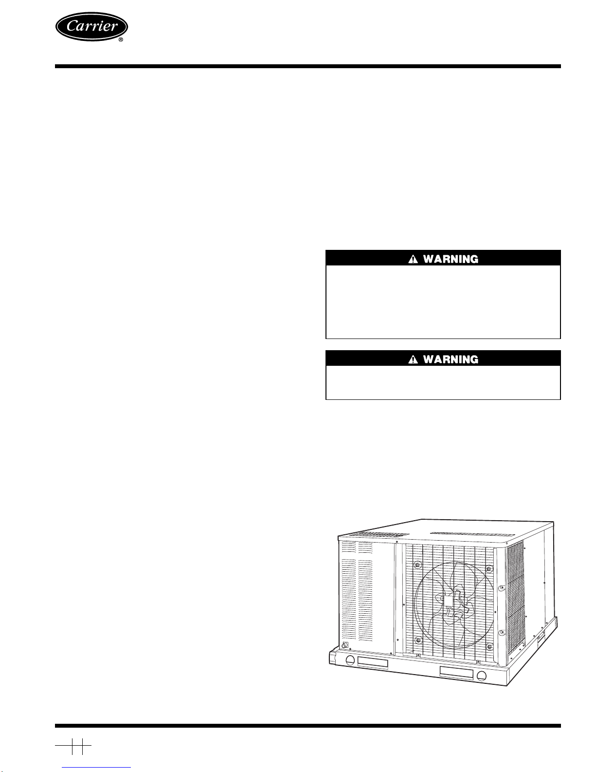
General — The 48HX units (see Fig. 1) are fully self-
contained, combination electric heat pump units with
gas-fired back-up heat. The units are designed for outdoor
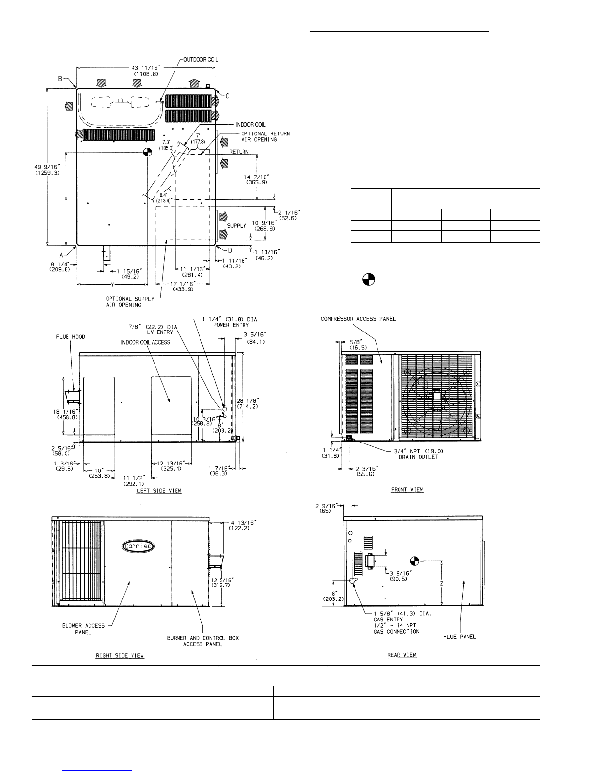
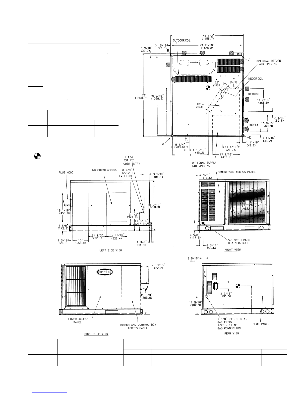
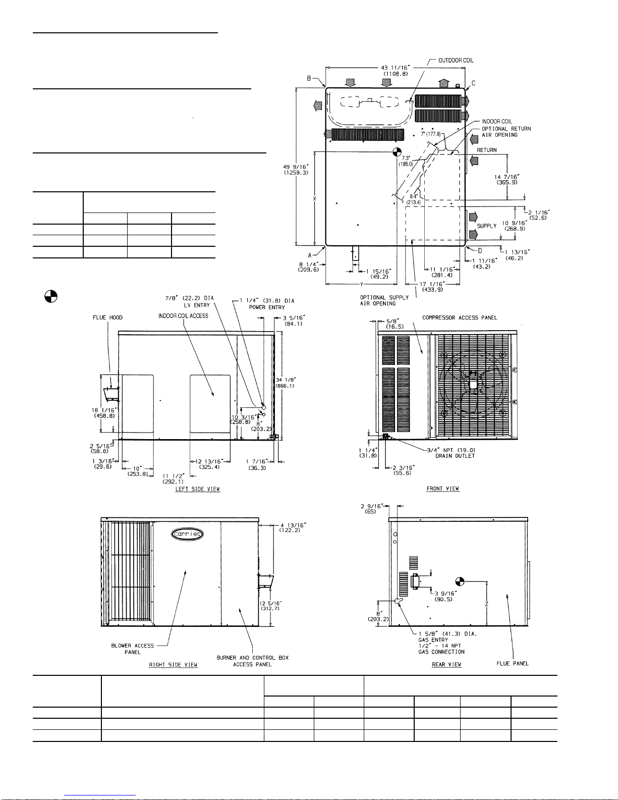
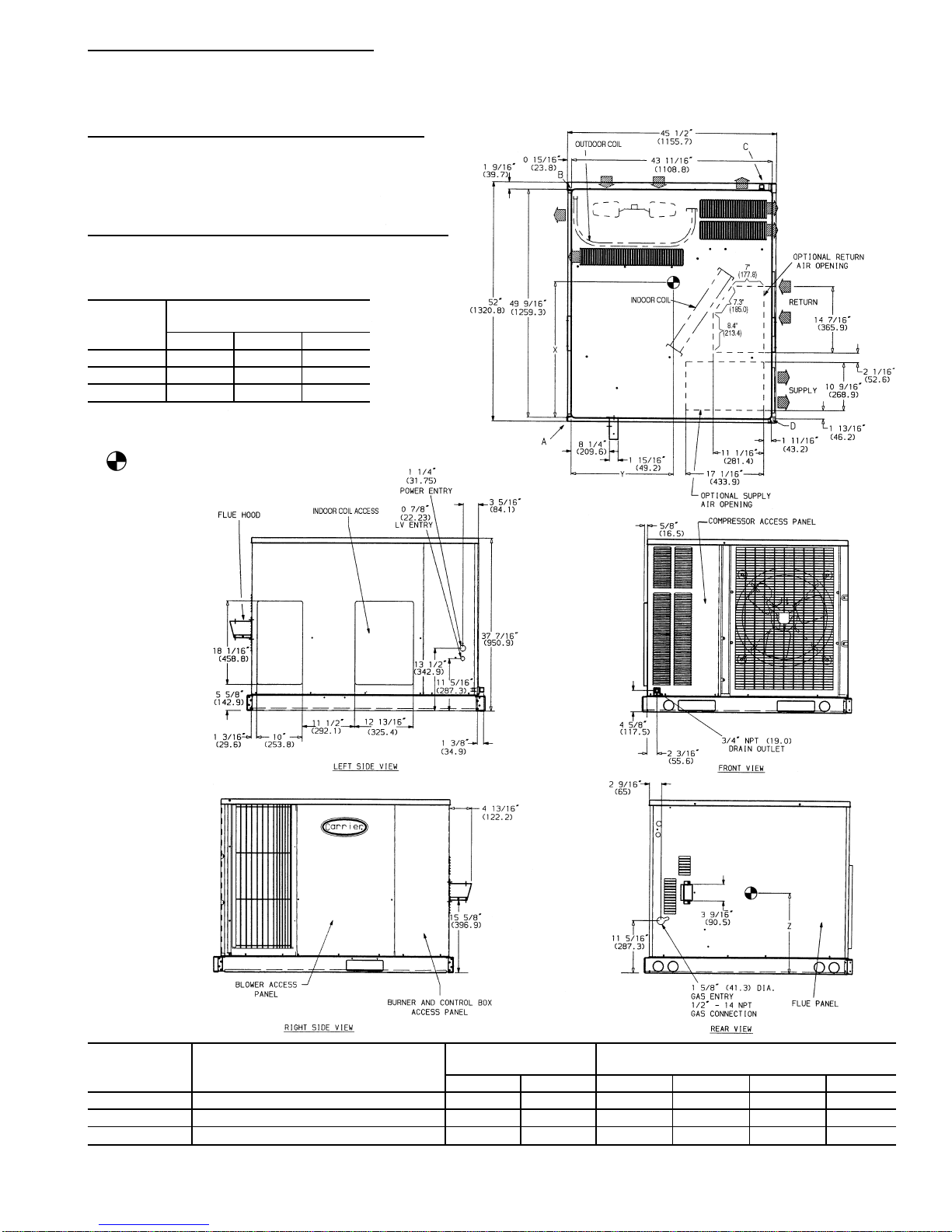
installation. See Fig. 2-5 for unit dimensions. All unit sizes
have discharge openings for both horizontal and downflow configurations, and are factory shipped with all 4 duct
openings covered. Units may be installed either on a rooftop
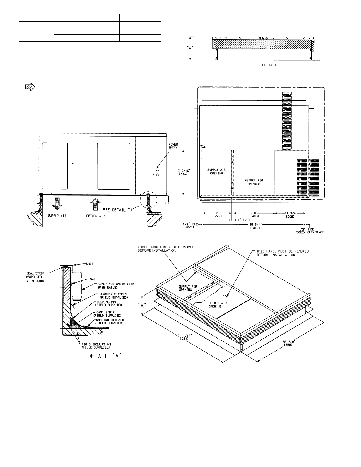
or a ground-level cement slab. See Fig. 6 for roof curb
dimensions.
Fig.1—Typical 48HX Unit Shown with Optional
Base Rail
48HX030-060
Dual Fuel Heat Pump Units
Manufacturer reserves the right to discontinue, or change at any time, specifications or designs without notice and without incurring obligations.
Book 1 4
Tab 5a 5a
PC 111 Catalog No. 534-722 Printed in U.S.A. Form 48HX-3SI Pg 1 9-98 Replaces: 48HX-2SI
Page 2
UNIT
48HX
ELECTRICAL
CHARACTERISTICS
UNIT WEIGHT
CORNER WEIGHT
(lb/kg)
lbkgABCD
030040 208/230-1-60, 208/230-3-60 346 157 99/45 69/31 120/55 58/26
030060 208/230-1-60, 208/230-3-60 358 163 102/46 72/33 123/56 61/28
UNIT
48HX
CENTER OF GRAVITY
(in./mm)
XYZ
030040 26.99/686 22.62/575 12.65/321
030060 26.90/684 22.62/575 12.65/321
NOTES:
1. Clearances must be maintained to prevent recirculation of air from outdoor-fan discharge.
2. indicates center of gravity.
REQ’D CLEARANCES FOR SERVICING. in. (mm)
Duct Panel .....................................0
Unit Top .................................36(914.4)
Side Opposite Ducts ........................36(914.4)
Compressor Access ........................36(914.4)
(Except for NEC requirements)
REQ’D CLEARANCES TO COMBUSTIBLE MAT’L. in. (mm)
Maximum Extension of Overhangs .............48(1219.2)
Unit Top .................................14(355.6)
Duct Side of Unit ............................2(50.8)
Side Opposite Ducts ........................14(355.6)
Bottom of Unit ...................................0
Flue Panel ...............................36(914.4)
NEC (National Electrical Code) REQ’D CLEARANCES. in. (mm)
Between Units, Control Box Side ..............42(1066.8)
Unit and Ungrounded Surfaces, Control Box Side . . . 36 (914.4)
Unit and Block or Concrete Walls and Other Grounded
Surfaces, Control Box Side .................42(1066.8)
Fig. 2 — Unit Dimensions, 48HX030 and 036 Without Base Rail
2
Page 3
UNIT
48HX
ELECTRICAL
CHARACTERISTICS
UNIT WEIGHT
CORNER WEIGHT
(lb/kg)
lbkgABCD
030040 208/230-1-60, 208/230-3-60 370 169 105/48 75/34 126/57 64/29
030060 208/230-1-60, 208/230-3-60 382 174 108/49 78/35 129/59 67/30
UNIT
48HX
CENTER OF GRAVITY
(in./mm)
XYZ
030040 26.85/682 23.25/590 15.96/405
030060 26.75/680 23.25/590 15.96/405
NOTES:
1. Clearances must be maintained to prevent recirculation of air from outdoor-fan discharge.
2. indicates center of gravity.
REQ’D CLEARANCES FOR SERVICING. in. (mm)
Duct Panel ...............................0
Unit Top ...........................36(914.4)
Side Opposite Ducts ..................36(914.4)
Compressor Access ..................36(914.4)
(Except for NEC requirements)
REQ’D CLEARANCES TO COMBUSTIBLE MAT’L.
in. (mm)
Maximum Extension of Overhangs .......48(1219.2)
Unit Top ...........................14(355.6)
Duct Side of Unit ..................... 2(50.8)
Side Opposite Ducts ..................14(355.6)
Bottom of Unit .............................0
Flue Panel .........................36(914.4)
NEC (National Electrical Code) REQ’D CLEARANCES
in. (mm)
Between Units, Control Box Side ........42(1066.8)
Unit and Ungrounded Surfaces, Control
Box Side .........................36(914.4)
Unit and Block or Concrete Walls and Other
Grounded Surfaces, Control Box Side ....42(1066.8)
Fig. 3 — Unit Dimensions, 48HX030 With Optional Base Rail
3
Page 4
UNIT
48HX
ELECTRICAL
CHARACTERISTICS
UNIT WEIGHT
CORNER WEIGHT
(lb/kg)
lb kg A B C D
036060/080 208/230-1-60, 208/230-3-60 460-3-60 432 196 111/50 88/40 160/73 73/33
048080/100 208/230-1-60, 208/230-3-60 432 196 111/50 88/40 160/73 73/33
060080/100 208/230-1-60, 208/230-3-60 463 210 119/54 96/44 167/76 81/37
UNIT
48HX
CENTER OF GRAVITY
(in./mm)
XYZ
036060/080 28.38/720 22.75/604 15.35/390
048080/100 28.38/720 23.75/604 15.35/390
060080/100 28.06/713 23.60/599 15.35/390
NOTES:
1. Clearances must be maintained to prevent recirculation of air from outdoor-fan discharge.
2. indicates center of gravity.
REQ’D CLEARANCES FOR SERVICING. in. (mm)
Duct Panel ......................................0
Unit Top ..................................36(914.4)
Side Opposite Ducts .........................36(914.4)
Compressor Access .........................36(914.4)
(Except for NEC requirements)
REQ’D CLEARANCES TO COMBUSTIBLE MAT’L. in. (mm)
Maximum Extension of Overhangs ..............48(1219.2)
Unit Top ..................................14(355.6)
Duct Side of Unit .............................2(50,8)
Side Opposite Ducts .........................14(355.6)
Bottom of Unit ....................................0
Flue Panel ................................36(914.4)
NEC (National Electrical Code) REQ’D CLEARANCES. in. (mm)
Between Units, Control Box Side ...............42(1066.8)
Unit and Ungrounded Surfaces, Control Box Side ....36(914.4)
Unit and Block or Concrete Walls and Other Grounded
Surfaces, Control Box Side ...................42(1066.8)
Fig. 4 — Unit Dimensions, 48HX036-060 Without Base Rail
4
Page 5
UNIT
48HX
ELECTRICAL
CHARACTERISTICS
UNIT WEIGHT
CORNER WEIGHT
(lb/kg)
lb kg A B C D
036060/080 208/230-1-60, 208/230-3-60, 460-3-60 456 207 117/53 94/43 166/75 79/36
048080/100 208/230-1-60, 208/230-3-60 456 207 117/53 94/43 166/75 79/36
060080/100 208/230-1-60, 208/230-3-60 487 221 125/57 102/46 173/79 87/40
UNIT
48HX
CENTER OF GRAVITY
(in./mm)
XYZ
036060/080 28.16/716 24.50/622 18.66/474
048080/100 28.16/716 24.50/622 18.66/474
060080/100 27.90/709 24.30/618 18.66/474
NOTES:
1. Clearances must be maintained to prevent recirculation of air from outdoor-fan discharge.
2. indicates center of gravity.
Fig. 5 — Unit Dimensions, 48HX036-060 With Optional Base Rail
REQ’D CLEARANCES FOR SERVICING. in. (mm)
Duct Panel ......................................0
Unit Top ..................................36(914.4)
Side Opposite Ducts .........................36(914.4)
Compressor Access .........................36(914.4)
(Except for NEC requirements)
REQ’D CLEARANCES TO COMBUSTIBLE MAT’L. in. (mm)
Maximum Extension of Overhangs ..............48(1219.2)
Unit Top ..................................14(355.6)
Duct Side of Unit .............................2(50.8)
Side Opposite Ducts .........................14(355.6)
Bottom of Unit ....................................0
Flue Panel ................................36(914.4)
NEC (National Electrical Code) REQ’D CLEARANCES. in. (mm)
Between Units, Control Box Side ...............42(1066.8)
Unit and Ungrounded Surfaces, Control Box Side ....36(914.4)
Unit and Block or Concrete Walls and Other Grounded
Surfaces, Control Box Side ...................42(1066.8)
5
Page 6
PART NUMBER ‘‘A’’
FLAT
CPRFCURB001A00 89 [203]
CPRFCURB002A00 119 [279]
CPRFCURB003A00 149 [356]
NOTES:
1. Roof curb must be set up for unit being installed.
2. Seal strip must be applied as required for unit being installed.
3. Dimensions in [ ] are in millimeters.
4. Roof curb is made of 16 gage steel.
5. Attach ductwork to curb (flanges of duct rest on curb).
6. Service clearance 4 ft on each side.
7. Direction of airflow.
8. Insulated panels: 1-in. thick fiberglass 1 lb density.
Fig. 6 — Roof Curb Dimensions
6
Page 7
RECEIVING AND INSTALLATION
Step 1 — Check Equipment
IDENTIFYUNIT — The unit model number and serial number are stamped on unit identification plate. Check this
information against shipping papers and job data.
INSPECT SHIPMENT — Inspect for shipping damage while
unit is still on shipping pallet. If unit appears to be damaged
or is torn loose from its anchorage, have it examined by transportation inspectors before removal. Forward claim papers
directly to transportation company. Manufacturer is not responsible for any damage incurred in transit.
Check all items against shipping list. Immediately notify
the nearest Carrier Air Conditioning office if any item is
missing.
To prevent loss or damage, leave all parts in original packages until installation.
Step 2 — Provide Unit Support
ROOF CURB — Install accessory roof curb in accordance
with instructions shipped with curb. See Fig. 6 for roof curb
dimensions. Install insulation, cant strips, roofing, and flashing. Ductwork must be attached to curb.
IMPORTANT: The gasketing of the unit to the roof
curb is critical for a watertight seal. Install gasketing
material supplied with the roof curb. Improperly applied gasketing can also result in air leaks and poor
unit performance.
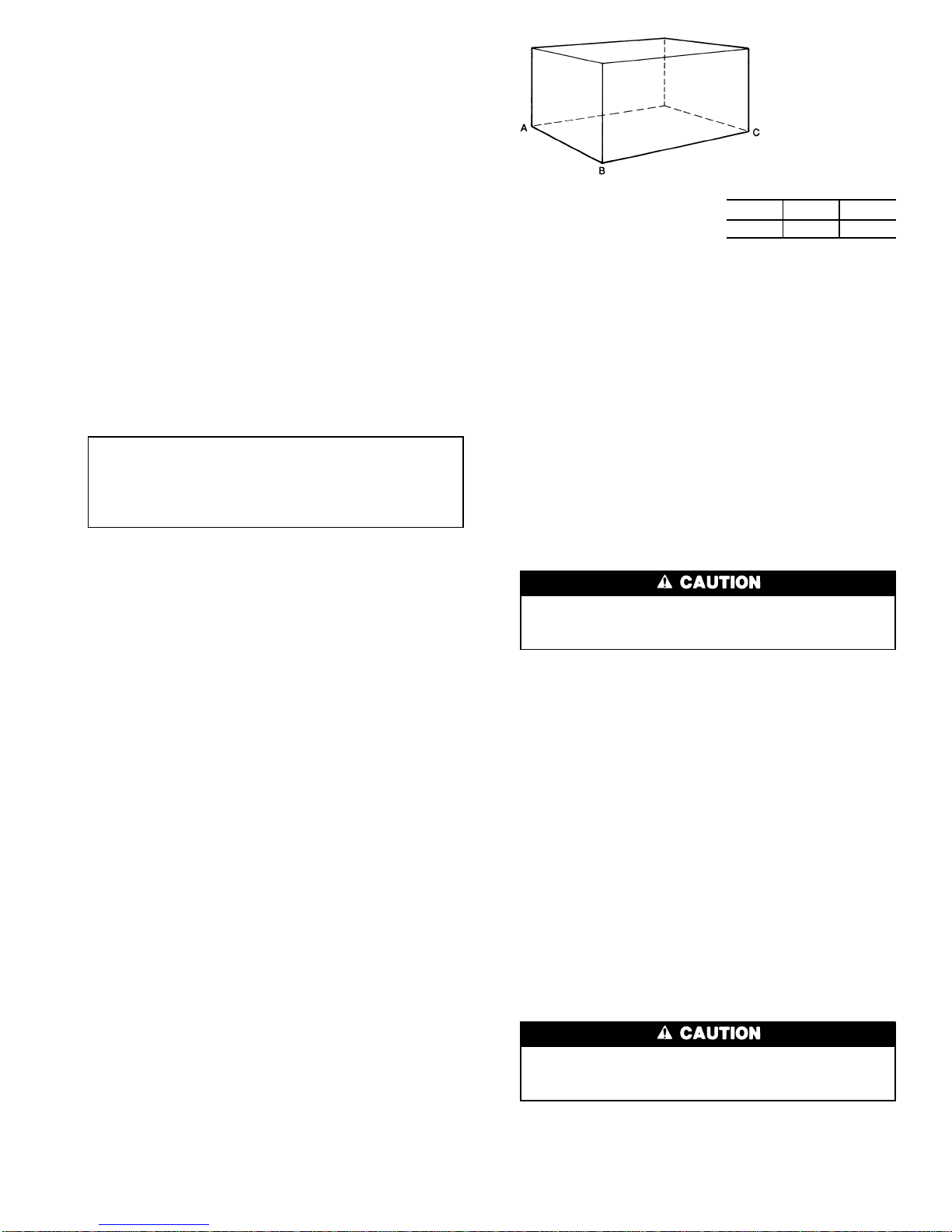
Curb should be level to within1⁄4inch. See Fig. 7. This
is necessary for unit drain to function properly. Refer to
accessory roof curb installation instructions for additional
information as required.
To remove wood support under unit (with base rail only),
loosen 4 screws above rigging holes and slide assembly out
through rectangular hole.
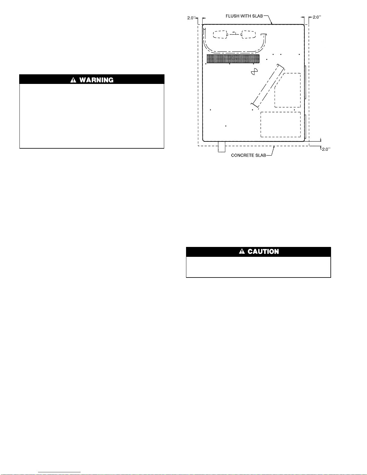
SLAB MOUNT — Place the unit on a solid, level concrete
pad that is a minimum of 4 in. thick with 2 in. above grade.
The slab should be flush on the front of the unit (to allow
condensate drain installation) and should extend 2 in. on the
three remaining sides of the unit. See Fig. 8. Install a 6-in.
gravel apron in front of outdoor-air inlets to prevent obstruction of airflow by grass or shrubs. Do not secure the unit to
the slab except when required by local codes.
To remove wood support under unit (with base rail only),
loosen 4 screws above rigging holes and slide assembly out
through rectangular hole.
FLUSH MOUNT — Place side of unit with duct panel
flush against transition. On units with optional base rails, the
skirt on duct-panel side of unit can be removed or relocated
to allow unit to be mounted flush against transitions that extend below basepan of unit. To move skirt, proceed as
follows:
1. Remove 4 screws holding skirt to base rail. Retain screws.
2. Remove skirt or slide skirt inwards until alternate clear-
ance holes align with base rails.
3. Secure with screws removed in Step 1. Holes align with
base rails.
To remove wood support under unit (with base rail only),
loosen 4 screws above rigging holes and slide assembly out
through rectangular hole.
Step 3 — Field Fabricate Ductwork — Secure all
ducts to roof curb and building structure on vertical discharge units. Do not connect ductwork to unit. For horizontal applications, attach ductwork to flanges on horizontal
discharge openings. All ductwork should be secured to the
flanges. Insulate and weatherproof all external ductwork, joints,
and roof openings with counter flashing and mastic in accordance with applicable codes.
Ducts passing through an unconditioned space must be
insulated and covered with a vapor barrier.
If a plenum return is used on a vertical unit, the return
should be ducted through the roof deck to comply with applicable fire codes.
A minimum clearance is not required around ductwork.
Cabinet return-air static shall not exceed −.25 in. wg.
Step 4 — Provide Clearances — The required mini-
mum operating and service clearances are shown in
Fig. 2-5. Adequate combustion, ventilation, and outdoor air
must be provided.
Do not restrict outdoor airflow. An air restriction at either the outdoor-air inlet or the fan discharge can be detrimental to compressor life.
The outdoor fan pushes air through the outdoor coil and
discharges it through the bank of louvers in the top cover,
the decorative grille on the right side of the unit, and the
compressor access panel. Be sure that the fan discharge does
not recirculate to the outdoor coil. Do not locate the unit in
either a corner or under an overhead obstruction. The minimum clearance of a partial overhang (such as a normal house
overhang) is 48-inches. The maximum horizontal extension
of a partial overhang must not exceed 48 inches.
Provide a minimum clearance of 42 in. for the control box
side next to a block wall or any other grounded surface. Provide a minimum clearance of 42 in. between the control box
side of unit and any electrically powered device, for example, another unit.
Do not place the unit where water, ice, or snow from an
overhang or roof will damage or flood the unit. Do not install the unit on carpeting, tile, or other combustible materials. The unit may be installed on wood flooring or on
Class A, B, or C roof covering materials.
Step 5 — Rig and Place Unit
When installing the unit on a rooftop, be sure the roof
will support the additional weight. Refer to Fig. 2-5 for
corner weight information.
Use spreader bars or crate top when rigging the unit. The
units must be rigged for lifting as shown in Fig. 9. Refer to
T able1 for operating weight and to Fig. 2-5 for corner weights.
MAXIMUM ALLOWABLE
DIFFERENCE (in.)
A-B B-C A-C
1
⁄
2
1
⁄
4
1
⁄
4
Fig. 7 — Unit Leveling Tolerances
7
Page 8
Use extreme caution to prevent damage when moving the
unit. Unit must remain in an upright position during all rigging and moving operations. The unit must be level for proper
condensate drainage; therefore, the ground-level pad or
accessory roof curb must be level before setting the unit in
place. When a field-fabricated support is used, be sure that
the support is level and properly supports the unit.
UNITS WITHOUT BASE RAIL — If accessory rigging
brackets are to be used for rigging, install them as follows:
Secure screws and paint protectors solidly against unit
basepan to hold lifting brackets in position.
Never use lifting brackets when the temperature is below −10 F.
Never exceed 200 lbs per bracket of lifting force.
Never use lifting brackets for lifting other models of air-
conditioning units or heat pumps.
Lifting point should be directly over the unit center of
gravity.
1. Position brackets as close to the corners of unit as possible. Be sure brackets are well outside of center of gravity. (See Fig. 2, 4, and 9.)
2. Position paint protectors and foam strips between screws
and painted surface of unit. Tighten screws until they make
contact with the paint protectors.
3. Secure device or hook of sufficientstrength to hole in bracket
as shown in detail ‘‘C’’ of Fig. 9.
4. If wood top is available, use it for a spreader bar to prevent straps from damaging unit. If wood top is not available, use spreader bars of sufficient length.
UNITS WITH OPTIONAL BASE RAIL — Refer to
Fig. 9, detail A and View B-B. Lifting holes are provided in
optional base rail as shown in Fig. 9. Operating weights are
shown in Table 1. Refer to rigging instructions on unit.
Protective wood support must be removed from unit before unit is mounted to curb. Remove 4 screws that secure
support above rigging holes in rails. Slide support out through
rectangular hole in rail. See Fig. 9.
Step 6 — Connect Condensate Drain
NOTE: When installing condensate drain connection be sure
to comply with local codes and restrictions.
Model 48HX disposes of condensate water through a
3
⁄4in. NPT fitting which exits through the compressor access
panel. See Fig. 2-5 for location.
Condensate water can be drained directly onto the roof in
rooftop installations (where permitted) or onto a gravel apron
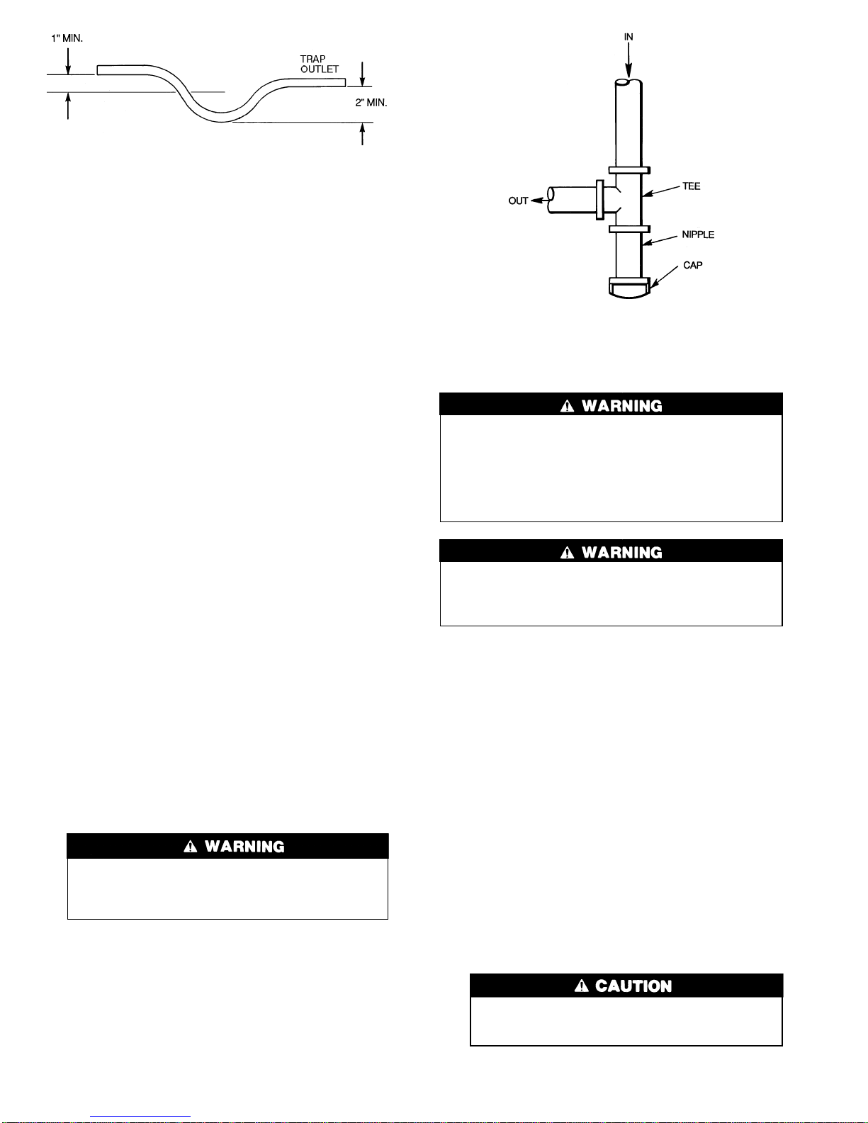
in ground-level installations. Install a field-supplied condensate trap at end of condensate connection to ensure proper
drainage. Make sure that the outlet of the trap is at least
1 in. lower than the drain-pan condensate connection to prevent the pan from overflowing. See Fig. 10. Prime the trap
with water. When using a gravel apron, make sure it slopes
away from the unit.
If the installation requires draining the condensate water
away from the unit, install a 2-in. trap at the condensate
connection to ensure proper drainage. See Fig. 10. Make sure
that the outlet of the trap is at least 1 in. lower than the drainpan condensate connection to prevent the pan from overflowing. Prime the trap with water. Connect a drain tube
using a minimum of
3
⁄4-in. PVC or3⁄4-in. copper pipe (all
field-supplied) at the outlet end of the 2-in. trap. Do not undersize the tube. Pitch the drain tube downward at a slope of
at least one in. for every 10 ft of horizontal run. Be sure to
check the drain tube for leaks.
Step 7 — Install Flue Hood — The flue hood as-
sembly is shipped screwed to the control box in the burner
compartment. Remove the burner access panel to locate the
assembly.
For units being installed in California Air Quality Man-
agement Districts which require NO
X
emissions of
40 nanograms/joule or less, kit CRLOWNOX001A00 must
be installed.
The venting system is designed to ensure proper venting. The flue hood assembly must be installed as indicated in this section of the unit installation instructions.
Install the flue hood as follows (refer to Fig. 2-5):
1. This installation must conform with local building codes
and with the National Fuel Gas Code (NFGC), American
National Standards Institute (ANSI) Z223.1 latest revision (in Canada, CAN/CGA [Canadian Gas Association]
B149.1, [2]-M86) or NFPA (National Fire Protection
Association) 54, latest revision TIA-54-84-1. Refer to
Provincial and local plumbing or wastewater codes and
other applicable local codes.
2. Remove from shipping location. Place vent cap assembly
over flue panel. Orient screw holes in vent cap with holes
in the flue panel.
3. Secure flue hood to flue panel by inserting a single
screw on the right side, the left side, and the top of flue
hood.
Step 8 — Install Gas Piping — The gas supply pipe
enters the unit through the access hole provided. The gas
connection to the unit is made to the1⁄2-in. FPT gas inlet on
the manual shutoff or gas valve.
Install a gas supply line that runs to the heating section.
Refer to Table 2 and the NFGC for gas pipe sizing. Black
iron pipe must be used for connections inside the unit. Check
the local utility for recommendations concerning existing lines.
Size gas supply piping for 0.5 in. wg maximum pressure drop.
Never use pipe smaller than the
1
⁄2-in. FPT gas inlet on the
unit gas valve.
Fig. 8 — Slab Mounting Details
8
Page 9
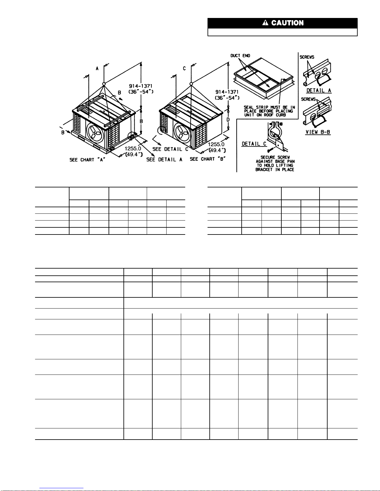
Table 1 — Physical Data
UNIT SIZE 48HX 030040 030060 036060 036080 048080 048100 060080 060100
NOMINAL CAPACITY (tons) 2
1
⁄
2
21⁄
2
334455
OPERATING WEIGHT (lb)
Without Base Rail 346 358 432 432 432 432 463 463
With Optional Base Rail 370 382 456 456 456 456 487 487
COMPRESSOR Scroll
Quantity 1
REFRIGERANT R-22
Charge (lb) 5.6 5.6 8.6 8.6 7.8 7.8 8.1 8.1
OUTDOOR COIL
Rows...Fins/in. 2...17 2...17 2...17 2...17 2...17 2...17 2...17 2...17
Face Area (sq ft) 7.00 7.00 8.66 8.66 8.66 8.66 8.66 8.66
OUTDOOR FAN (Propeller)
Nominal Cfm 2200 2200 2200 2200 2400 2400 2400 2400
Diameter (in.) 20 20 20 20 20 20 20 20
Motor Hp
1
⁄
4
1
⁄
4
1
⁄
4
1
⁄
4
1
⁄
3
1
⁄
3
1
⁄
3
1
⁄
3
Motor Rpm 1100 1100 1100 1100 1100 1100 1100 1100
INDOOR COIL
Rows...Fins/in. 3...15 3...15 4...15 4...15 4...15 4...15 4...15 4...15
Face Area (sq ft) 3.6 3.6 4.5 4.5 4.5 4.5 4.5 4.5
INDOOR FAN (Centrifugal)*
Nominal Airflow (Cfm) 1000 1000 1150 1150 1600 1600 1800 1800
Size (in.) 10x10 10x10 10x10 10x10 10x10 10x10 10x10 10x10
Motor Hp
1
⁄
4
1
⁄
4
1
⁄
4
1
⁄
2
1111
Motor Rpm 1075 1075 1100 1100 Variable Variable Variable Variable
FURNACE SECTION
Heating Input†
(Btuh) 40,000 56,000 56,000 80,000 80,000 95,000 80,000 95,000
Burner Orifice (Qty...drill size)
Natural Gas 1...32 2...41 2...41 2...32 2...32 2...30 2...32 2...30
Propane Gas 1...41 2...46 2...46 2...42 2...42 2...41 2...42 2...41
RETURN-AIR FILTERS**
Throwaway (in.) 24x24 24x24 24x30 24x30 24x30 24x30 24x30 24x30
*Sizes 048 and 060 indoor fans are equipped with an integrated con-
trol motor (ICM). The ICM provides variable speed.
†Based on an altitude of 0 to 2000 feet.
**Required filter sizes shown are based on the ARI (Air Conditioning
& Refrigeration Institute) rated heating airflow at a velocity of
300 ft/min for throwaway type or 450 ft/min for high capacity type.
Recommended filters are 1-in. thick.
All panels must be in place when rigging.
NOTICE TO RIGGERS
Hook rigging shackles through holes in lifting brackets, as shown in
Details ‘‘A’’ and ‘‘C.’’ Lifting brackets to be centered around the unit
center of gravity. Use wooden top skid when rigging, to prevent rigging straps from damaging unit. On units with rails, remove 4 screws
to slide wood support through rectangular hole in rail.
CHART ‘‘A’’ — UNITS WITH OPTIONAL BASE RAIL
UNIT SIZE
48HX
SHIPPING
WEIGHT
AB
Lb Kg in. mm in. mm
030 401 182 22.6 575 32.2 817
036 477 217 21.2 537 38.2 969
048 477 217 21.2 537 38.2 969
060 506 230 21.5 546 38.2 969
CHART ‘‘B’’ — UNITS WITHOUT BASE RAIL
UNIT SIZE
48HX
SHIPPING
WEIGHT
CD
Lb Kg in. mm in. mm
030 377 171 22.4 568 28.2 715
036 453 206 21.0 532 34.2 867
048 453 206 21.0 532 34.2 867
060 482 219 21.3 542 34.2 867
Fig. 9 — Suggested Rigging
9
Page 10
For natural gas applications, the gas pressure at unit gas
connection must not be less than 4.0 in. wg or greater than
13 in. wg while the unit is operating. For propane applications, the gas pressure must not be less than 4.0 in. wg or
greater than 13 in. wg at the unit connection.
When installing the gas supply line, observe local codes
pertaining to gas pipe installations. Refer to the NFGC
ANSI Z223.1 latest revision NFPA latest edition (in
Canada, CAN/CGA B149.1, (2)-M86). In the absence of
local building codes, adhere to the following pertinent
recommendations:
1. Avoid low spots in long runs of pipe. Grade all pipe
1
⁄4inch in every 15 ft to prevent traps. Grade all horizontal runs downward to risers. Use risers to connect to
heating section and to meter.
2. Protect all segments of piping system against physical and
thermal damage. Support all piping with appropriate straps,
hangers, etc. Use a minimum of one hanger every 6 ft.
For pipe sizes larger than
1
⁄2in., follow recommendations
of national codes.
3. Apply joint compound (pipe dope) sparingly and only to
male threads of joint when making pipe connections. Use
only pipe dope that is resistant to action of liquefied
petroleum gases as specified by local and/or national codes.
Never use Teflon tape.
4. Install sediment trap in riser leading to heating section
per Fig. 11. This drip leg functions as a trap for dirt and
condensate.
5. Install an accessible, external, manual main shutoff valve
in gas supply pipe within 6 ft of heating section.
6. Install ground-joint union close to heating section between unit gas valve and external manual gas shutoff
valve.
7. Pressure-test all gas piping in accordance with local and
national plumbing and gas codes.
NOTE: The gas valve in the unit is subject to failure if
exposed to pressures exceeding 0.5 psig. When pressurizing the gas line above 0.5 psig, disconnect the union
located between the manual shutoff and the gas valve in
the unit; this will avoid unit gas valve failure.
Never use a match or other open flame when checking for gas leaks. Never purge gas line into combustion chamber. Failure to follow this warning could
result in an explosion causing personal injury or death.
8. Using a soap and water solution, check for gas leaks at
all piping connections inside and outside the unit.
Step 9 — Install Duct Connections — The unit
has duct flanges on the supply- and return-air openings on
the side and bottom of the unit. See Fig. 2-5 for connection
sizes and locations.
CONFIGURING UNITS FOR DOWNFLOW (Vertical)
DISCHARGE
For vertical supply and return units, tools or parts
could drop into ductwork and cause an injury. Install
90-degree turns in the supply and return ductwork between the unit and the conditioned space. If a 90-degree
elbow cannot be installed, then grilles of sufficientstrength
and density should be installed to prevent objects from
falling into the conditioned space.
Before performing service or maintenance operations on
the system, turn off gas supply, then main power to unit.
Failure to follow this warning could result in electrical
shock and personal injury.
1. Open all electrical disconnects before starting any service work.
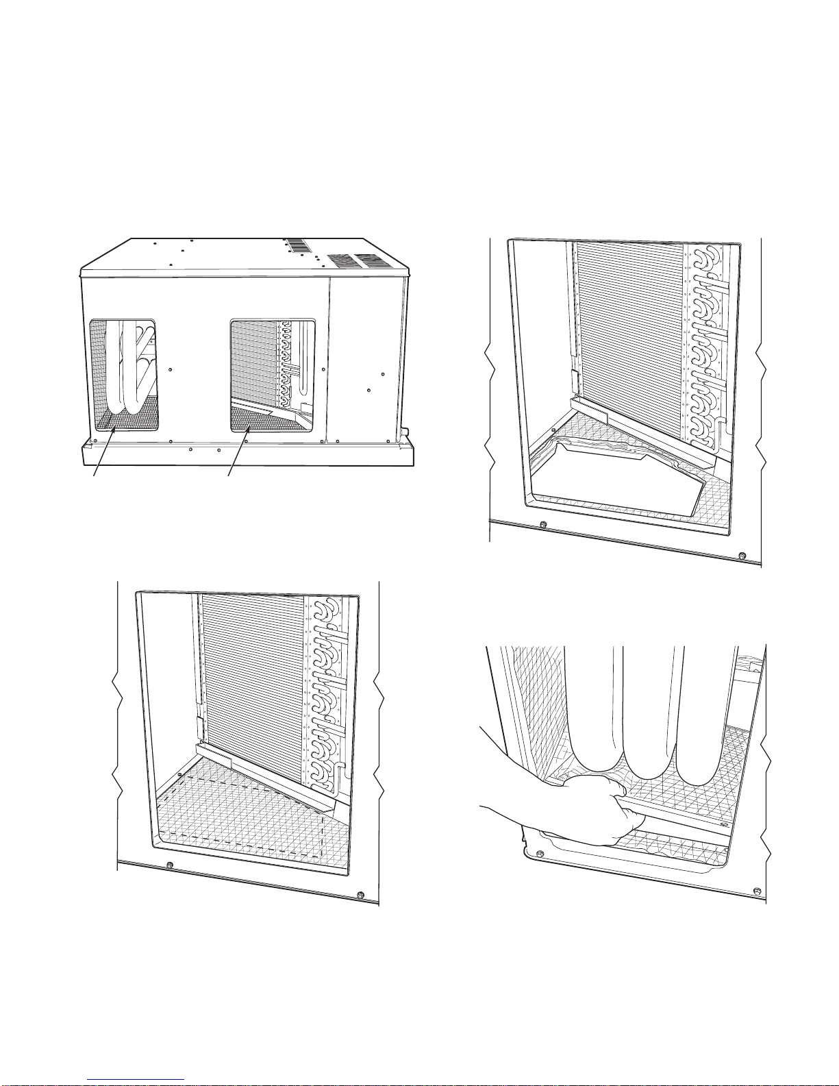
2. Remove return duct cover located on duct panel.
Figure 12 shows duct cover removed. Save duct cover
and screws.
3. Locate lances in basepan insulation that are placed
over the perimeter of the vertical duct opening cover
(Fig. 13).
4. Using a straight edge and sharp knife, cut and remove
the insulation around the perimeter of the cover. Remove and save 5 screws securing the cover to the basepan and slide out the cover. Discard the cover
(Fig. 14).
5. Remove supply duct cover located on duct panel.
Figure 12 shows duct cover removed. Save duct cover
and screws.
6. Remove and discard 2 screws which secure vertical discharge opening cover to basepan (Fig. 15). Slide cover
forward to disengage, then tilt and remove cover through
vertical discharge opening in bottom of unit. Discard duct
cover (Fig. 16).
Collect ALL screws that were removed. Do not leave
screws on rooftop as permanent damage to the roof
may occur.
Fig. 10 — Condensate Trap
Fig. 11 — Sediment Trap
10
Page 11
7. If unit ductwork is to be attached to vertical opening
flanges on the unit basepan (jackstand applications only),
do so at this time.
8. It is recommended that the basepan insulation around
the perimeter of the vertical return-air opening be secured to the basepan with aluminum tape. Applicable
local codes may require aluminum tape to prevent exposed fiberglass.
9. Cover both horizontal duct openings with the duct covers from Steps 2 and 5. Make sure opening is air- and
watertight.
10. After completing unit conversion, perform all safety checks
and power up unit.
NOTE: The design and installation of the duct system must
be in accordance with the standards of the NFPA for installation of nonresidence-type air conditioning and ventilating
systems, NFPA 90A or residence-type, NFPA 90B; and/or
local codes and residence-type, NFPA90B; and/or local codes
and ordinances.
SUPPLY DUCT OPENING RETURN DUCT OPENING
Fig. 12 — Supply and Return Duct Openings
Fig. 13 — Lance Location for Vertical Duct
Opening Cover
Fig. 14 — Vertical Duct Cover Removed
Fig. 15 — Removal of Vertical Discharge
Opening Cover
11
Page 12
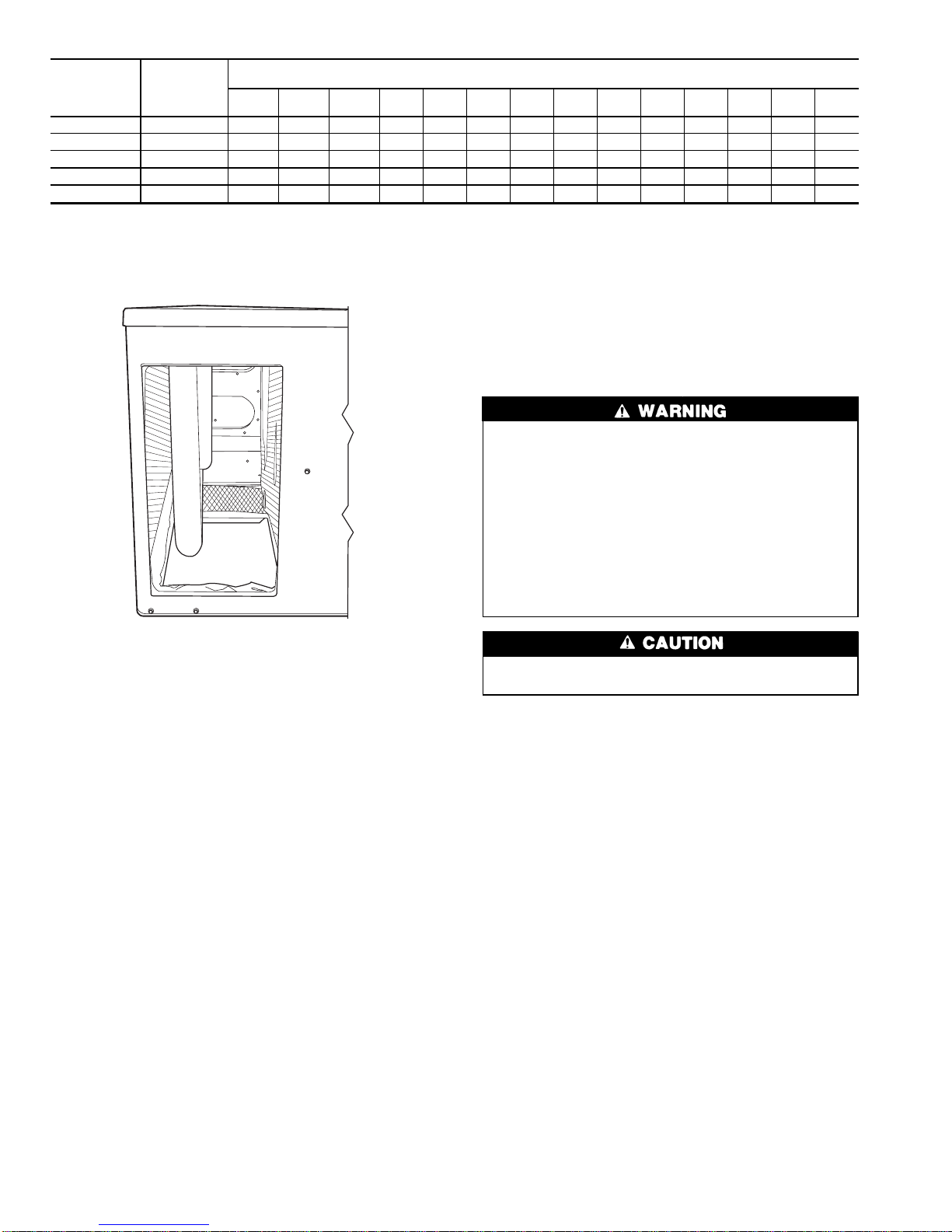
Table 2 — Maximum Gas Flow Capacity*
NOMINAL
IRON PIPE,
SIZE
(in.)
INTERNAL
DIAMETER
(in.)
LENGTH OF PIPE, FT†
10 20 30 40 50 60 70 80 90 100 125 150 175 200
1
⁄
2
.622 175 120 97 82 73 66 61 57 53 50 44 40 — —
3
⁄
4
.824 360 250 200 170 151 138 125 118 110 103 93 84 77 72
1 1.049 680 465 375 320 285 260 240 220 205 195 175 160 145 135
1
1
⁄
4
1.380 1400 950 770 600 580 530 490 460 430 400 360 325 300 280
1
1
⁄
2
1.610 2100 1460 1180 990 900 810 750 690 650 620 550 500 460 430
*Capacity of pipe in cu ft of gas per hr for gas pressure of 0.5 psig or less. Pressure drop of 0.5-in. wg
(based on a 0.60 specific gravity gas). Refer toTableC-4, National FireProtectionAssociation NFPA54.
†This length includes an ordinary number of fittings.
Adhere to the following criteria when selecting, sizing,
and installing the duct system:
1. Units are shipped with all 4 duct openings covered. Remove appropriate panels for intended installation.
2. Select and size ductwork, supply-air registers, and returnair grilles according to American Society of Heating, Refrigeration and Air Conditioning Engineers (ASHRAE)
recommendations.
3. Use flexible transition between rigid ductwork and unit
to prevent transmission of vibration. The transition may
be screwed or bolted to duct flanges. Use suitable gaskets
to ensure weathertight and airtight seal.
4. All units must have field-supplied filters or accessory filter rack installed in the return-air side of the unit. Recommended sizes for filters are shown in Table 1.
5. Size all ductwork for maximum required airflow (either
heating or cooling) for unit being installed. Avoid abrupt
duct size increases or decreases or performance may be
affected.
6. Adequately insulate and weatherproof all ductwork located outdoors. Insulate ducts passing through unconditioned space, and use vapor barrier in accordance with
latest issue of Sheet Metal and Air Conditioning Contractors National Association (SMACNA) and Air Conditioning Contractors of America (ACCA) minimum
installation standards for heating and air conditioning systems. Secure all ducts to building structure.
7. Flash, weatherproof, and vibration-isolate all openings in
building structure in accordance with local codes and good
building practices.
Step 10 — Install Electrical Connections
The unit cabinet must have an uninterrupted, unbroken
electrical ground to minimize the possibility of personal
injury if an electrical fault should occur. This ground
may consist of an electrical wire connected to the unit
ground lug in the control compartment, or conduit approved for electrical ground when installed in accordance with NEC (National Electrical Code) ANSI/
NFPA (latest edition) (in Canada, Canadian Electrical
Code CSA [Canadian Standards Association] C22.1) and
local electrical codes. Do not use gas piping as an elec-
trical ground. Failure to adhere to this warning could
result in personal injury or death.
Failure to follow these precautions could result in damage to the unit being installed:
1. Make all electrical connections in accordance with
NECANSI/NFPA(latest edition) and local electrical codes
governing such wiring. In Canada, all electrical connections must be in accordance with CSA standard C22.1
Canadian Electrical Code Part 1 and applicable local codes.
Refer to unit wiring diagram.
2. Use only copper conductor for connections between fieldsupplied electrical disconnect switch and unit. DO NOT
USE ALUMINUM WIRE.
3. Be sure that high-voltage power to unit is within operating voltage range indicated on unit rating plate.
4. Do not damage internal components when drilling through
any panel to mount electrical hardware, conduit, etc. On
3-phase units, ensure phases are balanced within 2 percent. Consult local power company for correction of
improper voltage and/or phase imbalance.
HIGH-VOLTAGE CONNECTIONS (Fig. 17) — The unit
must have a separate electrical service with a field-supplied,
waterproof, disconnect switch mounted at, or within sight
from, the unit. Refer to the unit rating plate for maximum
fuse/circuit breaker size and minimum circuit amps (ampacity) for wire sizing. See Table 3 for electrical data.
The field-supplied disconnect switch box may be mounted
on the unit over the high-voltage inlet hole when the
standard power and low-voltage entry points are used. See
Fig. 2-5 for acceptable location.
Fig. 16 — Vertical Discharge Cover
Removed
12
Page 13
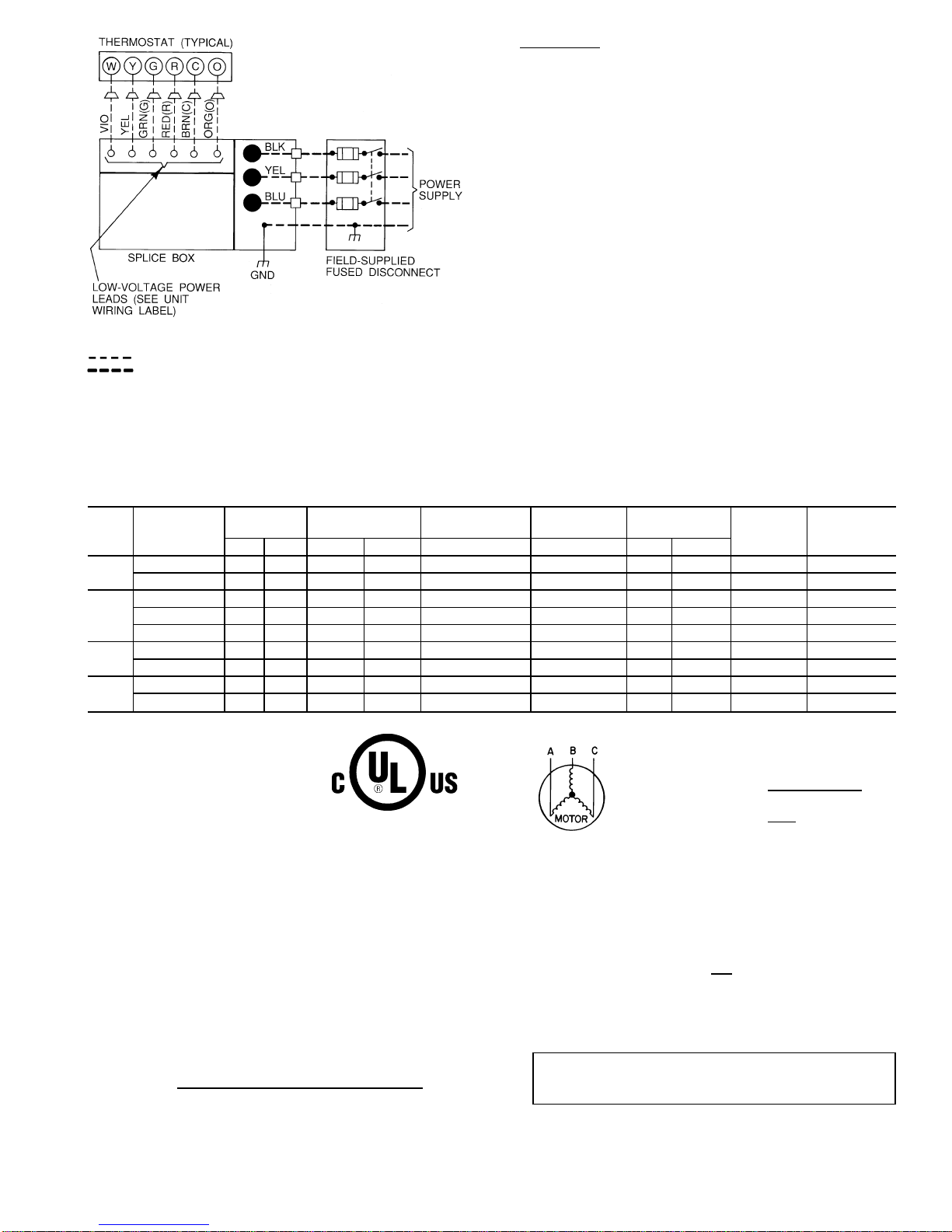
Power Entry
1. Remove knockouts in fixed compressor panel located on
duct panel side of unit.
2. Route high-voltage leads into high-voltage terminal box.
3. Connect ground wire to green-yellow wire using fieldsupplied splice.
4. Connect power wires to unit high-voltage leads.
5. On 3-phase units, locate blue wire projecting from compressor junction box. Cut wire at partition and route into
high-voltage junction box through grommet in back of
junction box.
6. On 3-phase units, strip back blue lead and connect to third
leg of the power wires. See Fig. 17.
Table 3 — Electrical Data
UNIT
SIZE
V-PH-Hz
VOLTAGE
RANGE
COMPRESSOR
OUTDOOR-FAN
MOTOR
INDOOR-FAN
MOTOR
POWER
SUPPLY
AWG 60C
MIN WIRE
SIZE
MAX WIRE
LENGTH (ft)
Min Max RLA LRA FLA FLA MCA MOCP*
030
208/230-1-60 187 253 15.0 73 1.4 2.6 22.8 30 10 100
208/230-3-60 187 253 10.1 71 1.4 2.8 16.6 25 12 75
036
208/230-1-60 187 253 16.0 88 1.2 2.6 24.4 40 10 90
208/230-3-60 187 253 10.3 77 1.2 2.6 17.3 25 12 65
460-3-60 414 506 5.1 39 0.7 1.3 8.7 10 14 100
048
208/230-1-60 187 253 26.4 129 1.4 7.2 41.6 60 6 100
208/230-3-60 187 253 15.0 99 1.4 7.2 27.4 40 10 70
060
208/230-1-60 187 253 32.1 169 2.1 7.2 49.4 60 6 100
208/230-3-60 187 253 19.3 123 2.1 7.2 33.4 50 8 100
LEGEND
AWG — American Wire Gage
FLA — Full Load Amps
HACR — Heating, Air Conditioning and
Refrigeration
LRA — Locked Rotor Amps
MCA — Minimum Circuit Amps
MOCP — Maximum Overcurrent Protection
RLA — Rated Load Amps
UL — Underwriters’ Laboratories
*Fuse or HACR breaker.
NOTES:
1. In compliance with NEC (National Electrical Code) requirements
for multimotor and combination load equipment (refer to NEC
Articles 430 and 440), the overcurrent protective device for the
unit shall be fuse or HACR breaker. The UL, Canada, units may
be fuse or circuit breaker.
2. Minimum wire size is based on 60 C copper wire. If other than
60 C wire is used, or if length exceeds wire length in table, determine size from NEC.
3. Unbalanced 3-Phase Supply Voltage
Never operate a motor where a phase imbalance in supply voltage is greater than 2%.
Use the following formula to determine
the percent of voltage imbalance.
% Voltage imbalance
max voltage deviation from average voltage
= 100 x
average voltage
EXAMPLE: Supply voltage is 460-3-60.
AB = 452 v
BC = 464 v
AC = 455 v
452 + 464 + 455
Average Voltage =
3
1371
=
3
= 457
Determine maximum deviation from average voltage.
(AB) 457 − 452=5v
(BC) 464 − 457=7v
(AC) 457 − 455=2v
Maximum deviation is 7 v.
Determine percent of voltage imbalance.
7
% Voltage Imbalance = 100 x
457
= 1.53%
This amount of phase imbalance is satisfactory as it is below the
maximum allowable 2%.
IMPORTANT: If the supply voltage phase imbalance is
more than 2%, contact your local electric utility company
immediately.
LEGEND
Field Control-Voltage Wiring
Field High-Voltage Wiring
NOTE: Use blue wire for 3-phase units only.
Fig. 17 — High- and Control-Voltage
Connections
13
Page 14
SPECIAL PROCEDURES FOR 208-V OPERATION
Make sure that the gas supply then the power supply to
the unit is switched OFF before making any wiring
changes. Electrical shock can cause personal injury or
death.
1. Disconnect the red transformer-primary lead from the contactor. See unit wiring label.
2. Remove the wirenut from the terminal on the end of the
blue transformer-primary lead.
3. Save the wirenut.
4. Connect the blue lead to the contactor terminal from which
the red lead was disconnected.
5. Using the wirenut removed from the blue lead, insulate
the loose terminal on the red lead.
6. Wrap the cover with electrical tape so that the metal terminal cannot be seen.
CONTROLVOLTAGE CONNECTIONS — Locate the room
thermostat on an inside wall in the space to be conditioned,
where it will not be subjected to either a cooling or heating
source or direct exposure to sunlight. Mount the thermostat
4 to 5 ft above the floor.
NOTE: Do not use any type of power-stealing thermostat.
Unit control problems may result.
Use no. 18 American Wire Gage (AWG) color-coded,
insulated (35 C minimum) wires to make the control voltage connections between the thermostat and the unit. If the
thermostat is located more than 100 ft from the unit (as
measured along the control voltage wires), use no.16 AWG
color-coded insulated (35 C minimum) wires.
Standard Connection (24 v) — Units Without Integrated
Control Motor (Size 030,036) — Remove knockout in compressor fixed panel located below high-voltage knockout. Remove the rubber grommet from the installer’s packet (included
with unit) and install grommet in the knockout opening. Route
thermostat wires through grommet providing drip loop at panel.
Connect low-voltage leads as shown in Fig. 17.
Routing Control Power Wires (24 v) — Integrated Control
Motor (ICM) Units (Size 048,060) — Remove knockout in
compressor fixed access panel located below high-voltage
knockout. Remove the rubber grommet from the installer’s
packet (included with unit) and install grommet in the knockout opening. Route thermostat wires through grommet providing drip loop at panel. Connect low-voltage leads to the
thermostat.
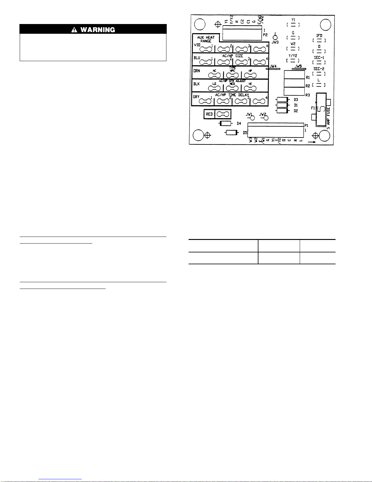
The Easy Select interface board is located in the burner
section. The Easy Select interface board is factory wired to
the motor, and factory default selections are preset. See
Fig. 18.
HEAT ANTICIPATOR SETTING — The room thermostat
heat anticipator must be properly adjusted to ensure proper
heating performance. Set the heat anticipator, using an ammeter between the W and R terminals, to determine the
exact required setting.
NOTE: For thermostat selection purposes, use 0.6 amp for
the approximate required setting.
Failure to make a proper heat anticipator adjustment will
result in improper operation, discomfort to the occupants
of the conditioned space, and inefficient energy utilization;
however, the required setting may be changed slightly
to provide a greater degree of comfort for a particular
installation.
Recommended thermostat and subbase is as follows:
TYPE
THERMOSTAT
PART NO.
SUBBASE
PART NO.
2-Stage Heat and 1-Stage
Cool, Auto, Changeover
HH07AT171 HH93AZ188
TRANSFORMER PROTECTION — The unit transformer
protection may be one of 2 types.
The first transformer type may contain an auto. reset overcurrent protector for control circuit protection. If this device
trips, it may reset without warning, starting the heating or
cooling section of this product. Use caution when servicing;
if overcurrent protector continues to trip, there is a problem
in the low-voltage electrical circuit, such as an electrical short,
ground, or transformer overload. Disconnect power, correct
the condition, and check for normal unit operation.
The second transformer type is of the energy-limiting type.
It is set to withstand a 30-second overload or shorted
secondary condition.
There is also a 5-amp fuse on integrated gas control (IGC)
board and Easy Select Interface Board to provide additional
overcurrent protection.
LEGEND
IFO — Indoor Fan On
JW — Jumper Wire
Fig. 18 — Easy Select Interface Board
14
Page 15
PRE-START-UP
Failure to observe the following warnings could result
in serious personal injury:
1. Follow recognized safety practices and wear protective goggles when checking or servicing refrigerant
system.
2. Do not operate compressor or provide any electric
power to unit unless compressor terminal cover is in
place and secured.
3. Do not remove compressor terminal cover until all
electrical sources are disconnected.
4. Relieve and recover all refrigerant from system before touching or disturbing anything inside terminal
box if refrigerant leak is suspected around compressor terminals.
5. Never attempt to repair soldered connection while refrigerant system is under pressure.
6. Do not use torch to remove any component. System
contains oil and refrigerant under pressure. To remove a component, wear protective goggles and proceed as follows:
a. Shut off gas supply and then electrical power to
unit.
b. Relieve and recover all refrigerant from system
using both high- and low-pressure ports.
c. Cut component connecting tubing with tubing cut-
ter and remove component from unit.
d. Carefully unsweat remaining tubing stubs when
necessary. Oil can ignite when exposed to torch
flame.
Proceed as follows to inspect and prepare the unit for ini-
tial start-up:
1. Remove all access panels.
2. Read and follow instructions on all WARNING, CAUTION, and INFORMATIONlabels attached to, or shipped
with, unit.
3. Make the following inspections:
a. Inspect for shipping and handling damages such as bro-
ken lines, loose parts, disconnected wires, etc.
b. Inspect for oil at all refrigerant tubing connections and
on unit base. Detecting oil generally indicates a refrigerant leak. Leak-test all refrigerant tubing connections using electronic leak detector, halide torch, or
liquid-soap solution. If a refrigerant leak is detected,
see Check for Refrigerant Leaks section below.
c. Inspect all field- and factory-wiring connections. Be
sure that connections are completed and tight.
d. Inspect coil fins. If damaged during shipping and
handling, carefully straighten fins with a fin comb.
4. Verify the following conditions:
Do not purge gas supply into the combustion chamber. Do not use a match or other open flame to check
for gas leaks. Failure to follow this warning could
result in an explosion causing personal injury or death.
a. Before lighting the unit for the first time, perform the
following: If the gas supply pipe was not purged before connecting the unit, it will be full of air. It is recommended that the ground joint union be loosened,
and the supply line be allowed to purge until the odor
of gas is detected. Never purge gas lines into a combustion chamber. Immediately upon detection of gas
odor, retighten the union. Allow 5 minutes to elapse,
then light unit.
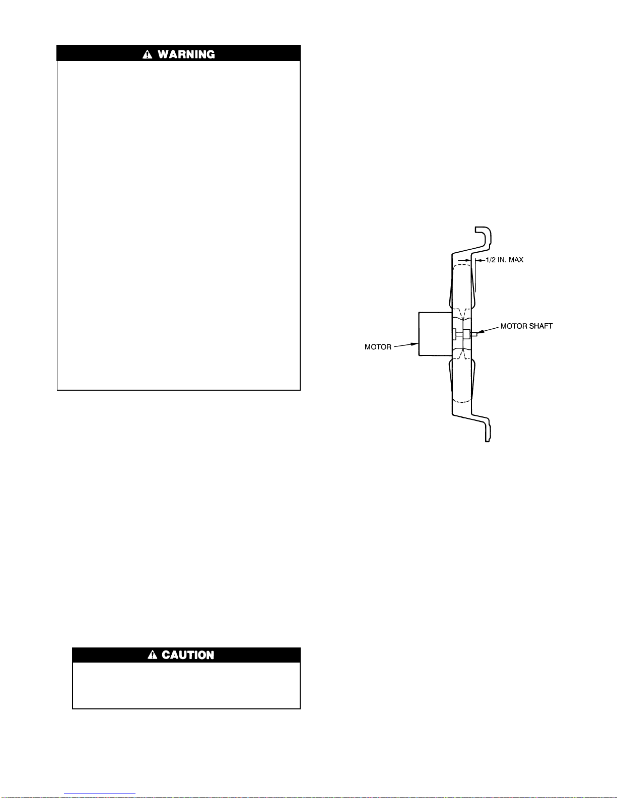
b. Make sure that outdoor-fan blade is correctly posi-
tioned in fan orifice. Leading edge of outdoor-fan blade
should be
1
⁄2in. maximum from plastic fan orifice (see
Fig. 19).
c. Make sure that air filter(s) is in place.
d. Make sure that condensate drain trap is filled with wa-
ter to ensure proper drainage.
e. Make sure that all tools and miscellaneous loose parts
have been removed.
START-UP
Check for Refrigerant Leaks —
Proceed as follows
to locate and repair a refrigerant leak and to charge the unit:
1. Locate leak and make sure that refrigerant system pressure has been relieved and reclaimed from both high- and
low-pressure ports.
2. Repair leak following accepted practices.
NOTE: Install a filter drier whenever the system has been
opened for repair.
3. Add a small charge of R-22 refrigerant vapor to system
and leak-test unit.
4. Evacuate and recover refrigerant from refrigerant system
if additional leaks are not found.
5. Charge unit with R-22 refrigerant, using a volumetriccharging cylinder or accurate scale. Refer to unit rating
plate for required charge. Be sure to add extra refrigerant
to compensate for internal volume of filter drier.
Fig. 19 — Fan Blade Clearance
15
Page 16
Start Up Heating Section and Make
Adjustments
Complete the required procedures given in Pre-Start-Up
section on page 15 before starting the unit.
Do not jumper any safety devices when operating the unit.
Make sure that burner orifices are properly aligned. Unstable operation may occur when the burner orifices in the
manifold are misaligned.
Follow the lighting instructions on the heating section
operation label (located inside the burner or blower access
door) to start the heating section.
NOTE: Make sure that gas supply has been purged, and that
all gas piping has been checked for leaks.
CHECK HEATING CONTROL — Start and check the unit
for proper heating control operation as follows: (See furnace
lighting instructions located inside burner or blower access
panel.)
1. Place the room thermostat SYSTEM switch in the HEAT
position and the fan switch in the AUTO. position.
2. Ensure that OAT (Outdoor-Air Thermostat) capillary is
above 55 F. Set the heating temperature control of the
thermostat above room temperature only enough to call
first-stage heat.
3. Observe compressor, outdoor fan, and indoor fan operate
in heat pump mode.
4. Set the heating temperature control of the thermostat enough
above room temperature to call second-stage heat.
5. Observe the induced-draft motor start.
6. After a call for second-stage heat, the main burner should
light within 5 seconds. If the burners do not light, there
is 22-second delay before another 5-second try. If the burners still do not light, this sequence is repeated. If the burners do not light within 15 minutes from the initial call for
heat, there is a lockout. To reset the control, break the
24-v power to W.
7. The indoor fan will turn on 45 seconds after the flame
has been established. The indoor fan will turn off
45 seconds after the thermostat has been satisfied.
CHECK GAS INPUT — Check gas input and manifold pressure after unit start-up. (See Table 4.) If adjustment is
required proceed as follows.
The rated gas inputs shown in Table 4 are for altitudes
from sea level to 2000 ft above sea level. These inputs are
based on natural gas with a heating value of 1050 Btu/ft
3
at
0.65 specific gravity, or propane gas with a heating value
of 2500 Btu/ft
3
at 1.5 specific gravity. For elevations above
2000 ft, reduce input 4% for each 1000 ft above sea level.
When the gas supply being used has a differentheating value
or specific gravity, refer to national and local codes, or contact your distributor to determine the required orifice size.
These units are designed to consume the rated gas inputs using the fixed orifices at specified manifold pressures as shown in Table 4. DO NOT REDRILL THE
ORIFICES UNDER ANY CIRCUMSTANCES.
ADJUST GAS INPUT — The gas input to the unit is
determined by measuring the gas flow at the meter or by
measuring the manifold pressure. Measuring the gas flow at
the meter is recommended for natural gas units. The manifold pressure must be measured to determine the input of
propane gas units.
Measure Gas Flow (Natural Gas Units) — Minor adjustment to the gas flow can be made by changing the manifold pressure. The manifold pressure must be maintained
between 3.4 and 3.6 in. wg. If larger adjustments are
required, change main burner orifices following the recommendations of national and local codes.
NOTE:All other appliances that use the same meter must be
turned off when gas flow is measured at the meter.
Proceed as follows:
1. Turn off gas supply to unit.
2. Remove pipe plug on manifold (see Fig. 20), then con-
nect manometer at this point. Turn on gas to unit.
3. Record number of seconds for gas meter test dial to make
one revolution.
4. Divide number of seconds in Step 3 into 3600 (number
of seconds in one hour).
5. Multiply result of Step 4 by the number of cu ft shown
for one revolution of test dial to obtain cu ft of gas flow
per hour.
6. Multiply result of Step 5 by Btu heating value of gas to
obtain total measured input in Btuh. Compare this value
with heating input shown in Table 4. (Consult the local
gas supplier if the heating value of gas is not known.)
EXAMPLE: Assume that the size of test dial is 1 cu ft, one
revolution takes 50 seconds, and the heating value of the gas
is 1050 Btu/ft
3
. Proceed as follows:
1. 50 seconds to complete one revolution.
2. 3600 ÷ 50 = 72.
3.72x1=72ft
3
of gas flow/hr.
4. 72 x 1050 = 75,600 Btuh input.
Table 4 — Rated Gas Inputs at Indicated Manifold Pressures
UNIT 48HX
NUMBER
OF
ORIFICES
GAS SUPPLY PRESSURE
(in. wg)
MANIFOLD
PRESSURE
(in. wg)
NATURAL GAS PROPANE*
Natural Propane
Orifice
Drill
Size
Heating
Input
(Btuh)†
Orifice
Drill
Size
Heating
Input
(Btuh)†
Min Max Min Max Natural Propane
030040 1 4.0 13.0 4.0 13.0 3.5 3.5 32 40,000 41 40,000
030060, 036060 2 4.0 13.0 4.0 13.0 3.5 3.5 41 56,000 46 54,000
036080, 048080,
060080
2 4.0 13.0 4.0 13.0 3.5 3.5 32 80,000 42 80,000
048100, 060100 2 4.0 13.0 4.0 13.0 3.5 3.5 30 95,000 41 95,000
*When a unit is converted to propane, different size orifices must be used. See separate natural-to-propane
conversion kit instructions.
†Based on altitudes from sea level to 2000 ft above sea level. For altitudes above 2000 ft, reduce input rating
4% for each additional 1000 ft. In Canada, from 2000 ft above sea level to 4500 ft above sea level, derate
the unit 10%.
16
Page 17
If the desired gas input is 80,000 Btuh, only a minor change
in the manifold pressure is required.
Observe manifold pressure and proceed as follows to ad-
just gas input:
1. Remove cover screw over regulator adjustment screw on
gas valve.
2. Turnregulator adjustment screw clockwise to increase gas
input, or turn regulator adjustment screw counterclockwise to decrease input. Manifold pressure must be between 3.4 and 3.6 in. wg.
Unsafe operation of the unit may result if manifold
pressure is outside this range. Personal injury or unit
damage may result.
3. Replace cover screw cap on gas valve.
4. Turn offgas supply to unit. Remove manometer from pressure tap and replace pipe plug on gas valve. Turn on gas
to unit and check for leaks.
Measure Manifold Pressure (Propane Units) — The main
burner orifices on a propane gas unit are sized for the unit
rated input when the manifold pressure is 3.5 in. wg.
Proceed as follows to adjust gas input on a propane gas
unit:
1. Turn off gas to unit.
2. Remove pipe plug on manifold (see Fig. 20), then connect manometer at this point.
3. Turn on gas to unit.
4. Remove cover screw over regulator adjustment screw on
gas valve.
5. Adjust regulator adjustment screw for a manifold pressure reading of 3.5 in. wg. Turn adjusting screw clockwise to increase manifold pressure, or turn adjusting screw
counterclockwise to decrease manifold pressure.
6. Replace cover screw.
7. Turn off gas to unit. Remove manometer from pressure
tap. Replace pipe plug on gas valve, then turn on gas to
unit. Check for leaks.
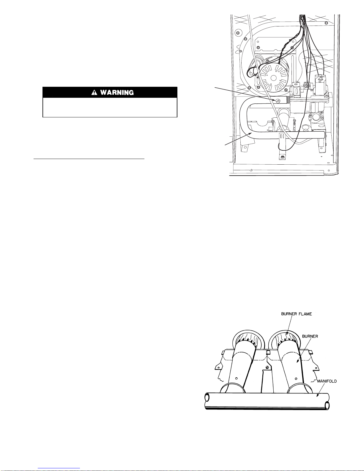
CHECK BURNER FLAME — With burner access panel removed, observe the unit heating operation. Watch the burner
flames to see if they are light blue and soft in appearance,
and that the flames are approximately the same for each burner.
See Fig. 21. Refer to Maintenance section for information
on burner removal.
AIRFLOWANDTEMPERA TURERISE — The heating section for each size unit is designed and approved for heating
operation within the temperature-rise range stamped on the
unit rating plate.
T able5 shows the approved temperature-rise range for each
heating input, and the air delivery cfm at various temperature rises. The heating operation airflow must produce a temperature rise that falls within the approved range.
Refer to Indoor Airflow and Airflow Adjustments section
on page 20 to adjust heating airflow when required.
LIMIT SWITCHES — Normally-closed limit switch (LS)
completes the control circuit through the thermostat R circuit. Should the leaving-air temperature rise above the maximum allowable temperature, the limit switch opens and the
R control circuit ‘‘breaks.’’Any interruption in the R control
circuit instantly closes the gas valve and stops gas flow
to the burners and pilot. The blower motor continues to run
until LS resets.
When the air temperature at the limit switch drops to the
low-temperature setting of the limit switch, the switch closes
and completes the R control circuit. The electric-spark ignition system cycles and the unit returns to normal heating
operation.
AUXILIARYLIMIT SWITCH — ROLLOUT — The function of the switch is to close the main gas valve in the event
of flame rollout. The switch is located above the main burners. When the temperature at the auxiliary switch reaches
the maximum allowable temperature, the R control circuit
trips, closing the gas valve and stopping gas flow to the burners. The indoor fan motor (IFM) and induced draft motor
continue to run until switch is reset.
PIPE
PLUG
MANIFOLD
Fig. 20 — Burner Assembly
Fig. 21 — Monoport Burners
17
Page 18
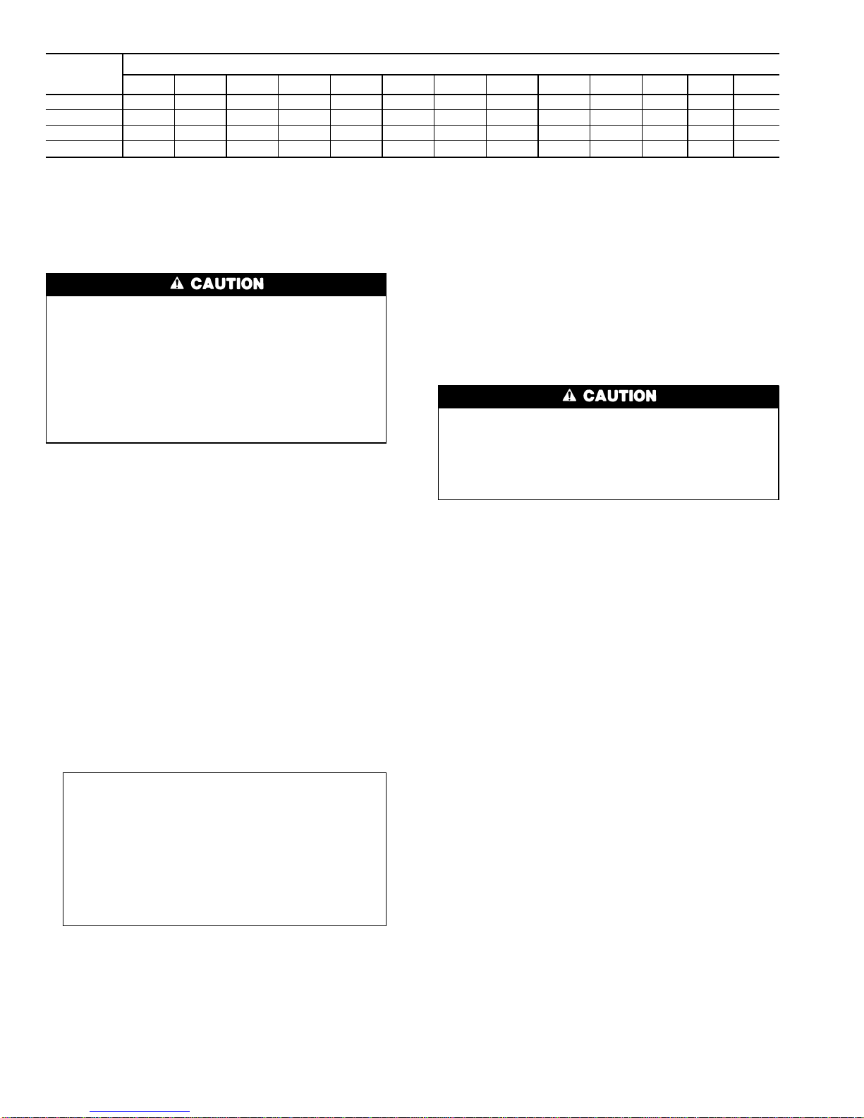
Table 5 — Air Delivery (Cfm) at Indicated Temperature Rise and Rated Heating Input
HEATING
INPUT
(Btuh)
TEMPERATURE RISE °F
20 25 30 35 40 45 50 55 60 65 70 75 80
40,000 1389 1111 926 794 694 617 556 — — — — — —
56,000 1944 1556 1296 1111 972 864 778 707 — — — — —
80,000 2778 2222 1852 1587 1389 1235 1111 1010 926 855 794 — —
95,000 3299 2639 2199 1885 1649 1466 1319 1199 1100 1015 942 880 825
NOTE: Dashed areas do not fall within the approved temperature rise range of the unit.
Start Up Cooling Section and Make
Adjustments
Complete the required procedures given in the PreStart-Up section on page 15 before starting the unit.
Do not jumper any safety devices when operating the
unit.
Do not operate the compressor when the outdoor temperature is below 40 F (unless accessory low-ambient
kit is installed).
Do not rapid-cycle the compressor. Allow 5 minutes between ‘‘on’’ cycles to prevent compressor damage.
CHECKING COOLING CONTROL OPERATION — Start
and check the unit for proper cooling control operation as
follows:
1. Place room thermostat SYSTEM switch in OFF position.
Observe that blower motor starts when FAN switch is placed
in ON position and shuts down when FANswitch is placed
in AUTO. position.
2. Place SYSTEM switch in COOL position and FANswitch
in AUTO. position. Set cooling control below room temperature. Observe that compressor, outdoor fan, and
indoor blower motors start. Observe that cooling cycle
shuts down when control setting is satisfied. The indoor
fan will continue to run for 30 seconds.
3. When using an auto.-changeover room thermostat, place
both SYSTEM and FAN switches in AUTO. positions.
Observe that unit operates in Heating mode when temperature control is set to ‘‘call for heating’’(above room
temperature) and operates in Cooling mode when temperature control is set to ‘‘call for cooling’’ (below room
temperature).
IMPORTANT: Three-phase, scroll compressor units
are direction-oriented. These units must be checked
to ensure proper compressor 3-phase power lead
orientation. If not corrected within 5 minutes, the
internal protector will shut off the compressor. The
3-phase power leads to the unit must be reversed to
correct rotation. When turning backwards, scroll compressors emit elevated noise levels, and the difference between compressor suction and discharge
pressures may be dramatically lower than normal.
CHECKINGANDADJUSTING REFRIGERANTCHARGE
— The refrigerant system is fully charged with R-22 refrigerant, tested, and factory-sealed.
NOTE: Adjustment of the refrigerant charge is not required
unless the unit is suspected of not having the proper R-22
charge.
A superheat charging label is attached to the inside of the
compressor access door.The label includes a ‘‘SuperheatCharging Table’’and a ‘‘Required Suction-Tube (F) Temperature’’
chart.
An accurate superheat, thermocouple-, or thermistor-type
thermometer, a sling psychrometer, and a gage manifold are
required when using the superheat charging method for evaluating the unit charge. Do not use mercury or small dial-type
thermometers because they are not adequate for this type of
measurement.
When evaluating the refrigerant charge, an indicated
adjustment to the specified factory charge must always
be very minimal. If a substantial adjustment is indicated, an abnormal condition exists somewhere in the
cooling system, such as insufficient airflow across either coil or both coils.
Proceed as follows:
1. Remove caps from low- and high-pressure service
fittings.
2. Using hoses with valve core depressors, attach low- and
high-pressure gage hoses to low- and high-pressure service fittings, respectively.
3. Start unit in Cooling mode and let unit run until system
pressures stabilize.
4. Measure and record the following:
a. Outdoor ambient-air temperature (F db).
b. Indoor inlet-air temperature (F wb).
c. Suction-tube temperature (F) at low-side service
fitting.
d. Suction (low-side) pressure (psig).
5. Using ‘‘SuperheatCharging Table,’’ compare outdoor-air
temperature (F db) with indoor inlet-air temperature
(F wb) to determine desired system operating superheat
temperature. See Tables 6A-6D.
6. Using ‘‘Required Suction-Tube Temperature (F)’’ table,
compare desired superheat temperature with suction (lowside) operating pressure (psig) to determine proper suctiontube temperature. See Table 7.
7. Compare actual suction-tube temperature with proper
suction-tube temperature. Using a tolerance of ± 3° F, add
refrigerant if actual temperature is more than 3° F higher
than proper suction-tube temperature, or remove refrigerant if actual temperature is more than 3° F lower than
required suction-tube temperature.
NOTE: If the problem causing the inaccurate readings is a
refrigerant leak, refer to Check for Refrigerant Leaks section on page 15.
18
Page 19
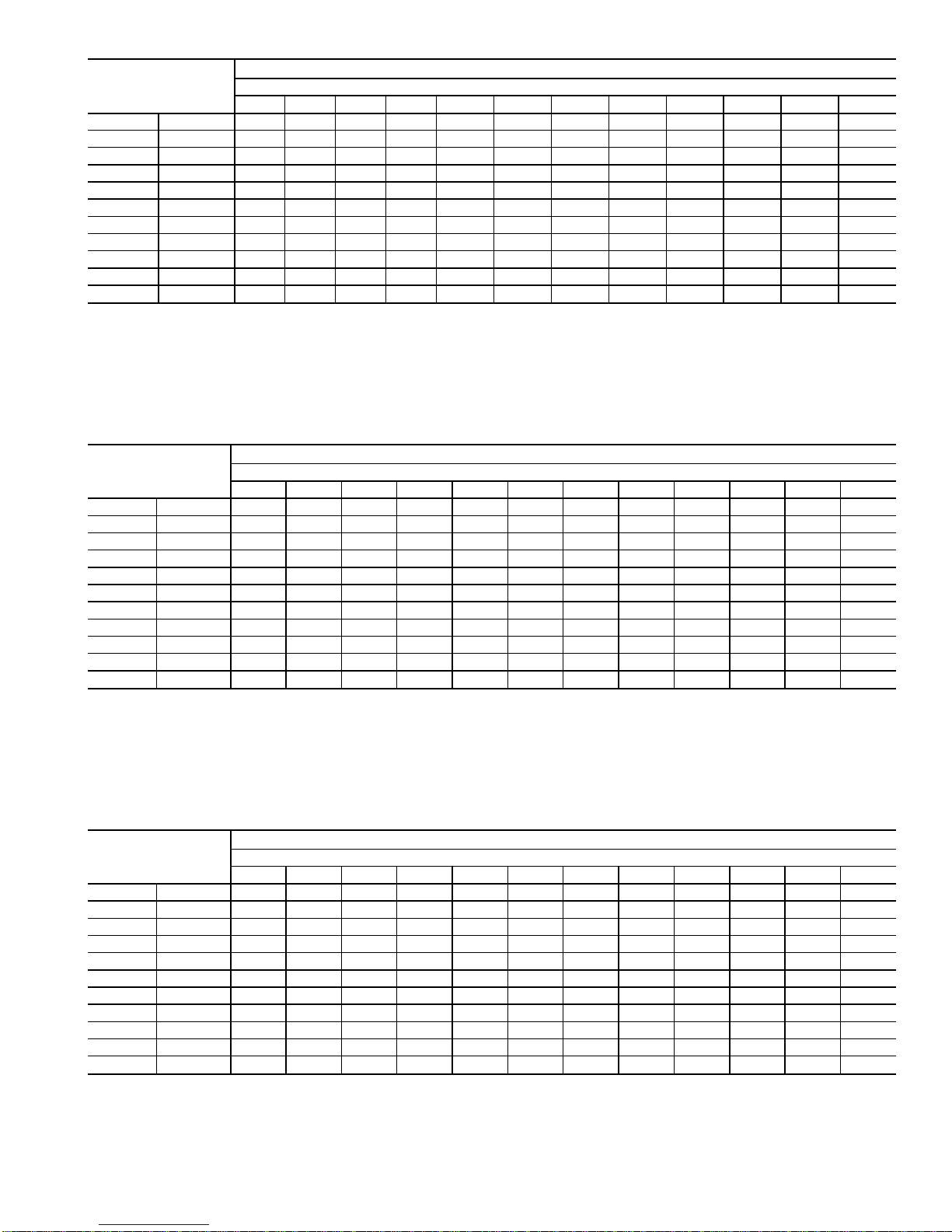
Table 6A — Superheat Charging Table, 48HX030
TEMP (F)
OUTDOOR
ENTERING AIR
INDOOR AIR — 1000 CFM
Indoor Air — Ewb (F)
54 56 58 60 62 64 66 68 70 72 74 76
65 SPH 5.5 5.5 5.5 5.5 12.5 19.6 26.6 26.9 27.2 27.5 26.5 25.4
70 SPH ****10.5 17.5 24.5 24.8 25.1 25.4 25.1 24.8
75 SPH ****8.415.5 22.5 22.8 23.1 23.4 23.8 24.2
80 SPH ****6.812.9 18.9 20.3 21.5 22.9 23.0 23.0
85 SPH ****5.110.2 15.4 17.7 20.1 22.3 22.1 21.8
90 SPH **** * 7.911.915.2 18.5 21.8 21.5 21.2
95 SPH **** * 5.68.412.7 17.0 21.2 20.8 20.6
100 SPH **** * * * 9.214.1 19.1 19.5 19.9
105 SPH **** * * * 5.711.417.1 18.2 19.3
110 SPH **** * * * 5.010.0 15.1 16.9 18.6
115 SPH **** ****8.713.0 15.5 18.0
LEGEND
Ewb — Entering Wet Bulb
SPH — Superheat at Compressor (F)
*Do not attempt to charge system under these conditions — refrigerant slugging may occur.
Table 6B — Superheat Charging Table, 48HX036
TEMP (F)
OUTDOOR
ENTERING AIR
INDOOR AIR — 1150 CFM
Indoor Air — Ewb (F)
54 56 58 60 62 64 66 68 70 72 74 76
65 SPH 28.6 28.6 28.6 30.4 32.1 33.3 34.3 33.4 32.0 30.7 29.8 28.9
70 SPH 23.8 23.8 23.8 25.5 27.2 29.5 32.3 32.0 30.9 29.7 28.6 27.6
75 SPH 19.0 19.0 19.1 20.6 22.2 25.7 30.4 30.6 29.7 28.7 27.5 26.3
80 SPH 14.9 15.0 15.0 15.8 16.5 21.1 26.5 27.7 27.8 27.8 26.6 25.3
85 SPH 10.9 10.9 10.9 10.9 10.9 16.6 22.6 24.8 25.9 26.9 25.6 24.3
90 SPH 7.6 7.7 7.7 7.0 8.3 12.6 19.1 21.5 23.4 25.3 24.4 23.6
95 SPH *****8.614.5 16.5 20.9 23.6 23.3 22.9
100 SPH ******11.314.3 17.4 20.4 21.1 21.8
105 SPH ******7.110.5 13.9 17.2 19.0 20.8
110 SPH *******7.111.716.4 18.2 19.9
115 SPH ********9.615.5 17.3 19.1
LEGEND
Ewb — Entering Wet Bulb
SPH — Superheat at Compressor (F)
*Do not attempt to charge system under these conditions — refrigerant slugging may occur.
Table 6C — Superheat Charging Table, 48HX048
TEMP (F)
OUTDOOR
ENTERING AIR
INDOOR AIR — 1600 CFM
Indoor Air — Ewb (F)
54 56 58 60 62 64 66 68 70 72 74 76
65 SPH 25.8 26.3 27.0 27.6 28.6 29.6 30.5 30.9 31.3 31.7 31.2 30.7
70 SPH 24.2 24.0 23.8 23.6 25.0 26.4 27.8 28.4 29.0 29.7 29.6 29.5
75 SPH 19.7 19.7 19.7 19.7 21.4 23.2 25.0 25.9 26.8 27.6 27.9 28.2
80 SPH 15.8 15.8 15.8 15.8 17.6 19.4 21.2 22.7 24.1 25.6 26.2 26.9
85 SPH 12.0 12.0 12.0 12.0 13.8 15.6 17.5 19.5 21.5 23.5 24.5 25.6
90 SPH 7.5 7.5 7.5 7.5 9.4 11.3 13.2 16.3 19.3 22.4 23.3 24.2
95 SPH ****5.07.09.013.1 17.1 21.2 22.0 22.8
100 SPH *******9.414.3 19.1 20.3 21.4
105 SPH *******5.711.417.1 18.6 20.1
110 SPH ********9.013.5 15.8 18.0
115 SPH ********6.710.0 13.0 16.0
LEGEND
Ewb — Entering Wet Bulb
SPH — Superheat at Compressor (F)
*Do not attempt to charge system under these conditions — refrigerant slugging may occur.
19
Page 20
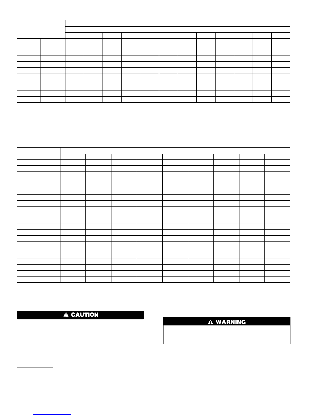
Table 6D — Superheat Charging Table, 48HX060
TEMP (F)
OUTDOOR
ENTERING AIR
INDOOR AIR — 1800 CFM
Indoor Air — Ewb (F)
54 56 58 60 62 64 66 68 70 72 74 76
65 SPH 21.0 21.0 21.0 21.0 22.8 24.7 26.5 27.8 29.1 30.4 29.5 28.6
70 SPH 16.5 16.5 16.5 16.5 18.8 21.1 23.5 25.2 27.0 28.8 28.2 27.6
75 SPH 12.0 12.0 12.0 12.0 14.8 17.6 20.4 22.7 24.9 27.2 26.9 26.6
80 SPH 10.5 10.5 10.5 10.5 12.7 14.9 17.1 19.8 22.5 25.2 25.4 25.5
85 SPH 9.0 9.0 9.0 9.0 10.6 12.3 13.9 17.0 20.0 23.1 23.8 24.5
90 SPH 4.5 4.5 4.5 4.5 6.5 8.5 10.5 14.3 18.1 21.9 22.7 23.5
95 SPH *****4.87.211.716.2 20.7 21.6 22.5
100 SPH ******3.68.613.6 18.6 20.0 21.4
105 SPH *******5.511.116.6 18.5 20.4
110 SPH ********10.0 15.5 17.5 19.4
115 SPH ********9.214.7 16.5 18.5
LEGEND
Ewb — Entering Wet Bulb
SPH — Superheat at Compressor (F)
*Do not attempt to charge system under these conditions — refrigerant slugging may occur.
Table 7 — Required Suction-Tube Temperature (F)*
SUPERHEAT
TEMP (F)
SUCTION PRESSURE AT SERVICE PORT (psig)
61.5 64.2 67.1 70.0 73.0 76.0 79.2 82.4 85.7
0 35 37 39 41 43 45 47 49 51
2 37 39 41 43 45 47 49 51 53
4 39 41 43 45 47 49 51 53 55
6 41 43 45 47 49 51 53 55 57
8 43 45 47 49 51 53 55 57 59
10 45 47 49 51 53 55 57 59 61
12 47 49 51 53 55 57 59 61 63
14 49 51 53 55 57 59 61 63 65
16 51 53 55 57 59 61 63 65 67
18 53 55 57 59 61 63 65 67 69
20 55 57 59 61 63 65 67 69 71
22 57 59 61 63 65 67 69 71 73
24 59 61 63 65 67 69 71 73 75
26 61 63 65 67 69 71 73 75 77
28 63 65 67 69 71 73 75 77 79
30 65 67 69 71 73 75 77 79 81
32 67 69 71 73 75 77 79 81 83
34 69 71 73 75 77 79 81 83 85
36 71 73 75 77 79 81 83 85 87
38 73 75 77 79 81 83 85 87 89
40 75 77 79 81 83 85 87 89 91
*Temperature at suction service valve.
INDOOR AIRFLOW AND AIRFLOW ADJUSTMENTS
For cooling operation, the recommended airflow is 350
to 450 cfm for each 12,000 Btuh of rated cooling capacity. For heating operation, the airflow must produce
a temperature rise that falls within the range stamped on
the unit rating plate.
T able5 shows the temperature rise at various airflow rates.
Size 030 and 036 — Table 8 shows both heating and cooling
airflows at various external static pressures for unit sizes 030
and 036. Refer to this table to determine the airflow for the
system being installed. See Table9 for wet coil pressure drop.
NOTE: Be sure that all supply- and return-air grilles are open,
free from obstructions, and adjusted properly.
Shut off gas supply then disconnect electrical power to
the unit before changing blower speed. Electrical shock
can cause personal injury or death.
Airflow can be changed by changing the lead connections
of the blower motor.
Unit 48HX030 is factory wired for medium speed; unit
48HX036 3-speed motors are factory wired for low speed.
20
Page 21
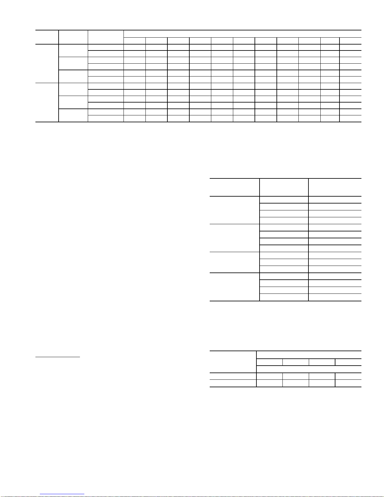
Table 8 — Dry-Coil Air Delivery* — Horizontal and Downflow Discharge at 230 and 460 V
— Size 030,036 (Deduct 10% from Cfm and Watts for 208 V Operation)
UNIT
48HX
MOTOR
SPEED
AIR
DELIVERY
EXTERNAL STATIC PRESSURE (in. wg)
0.0 0.1 0.2 0.3 0.4 0.5 0.6 0.7 0.8 0.9 1.0
030
Low
Watts 280 275 265 255 250 245 240 † † † †
Cfm 820 810 755 700 660 600 560 † † † †
Med
Watts 365 360 350 345 340 330 320 310 300 † †
Cfm 1025 1010 975 940 900 850 800 720 630 † †
High
Watts † † 490 480 470 460 445 430 410 390 380
Cfm † † 1300 1255 1200 1150 1080 1005 915 790 620
036
Low
Watts 420 395 385 370 360 350 † † † † †
Cfm 1265 1220 1170 1125 1065 1005 † † † † †
Med
Watts 545 525 500 480 460 445 425 405 355 † †
Cfm 1550 1485 1420 1355 1280 1210 1125 1035 910 † †
High
Watts ††††615585560535505465†
Cfm ††††1565 1460 1350 1230 1100 905 †
*Air delivery values are without air filter and are for dry coil. See
Table9 for wet coil pressure drop. Deduct field-supplied air filterpressure drop and wet coil pressure drop to obtain external static pressure available for ducting.
†Unit air delivery is outside of operating range.
NOTE: Do not operate the unit at a cooling airflow that is less
than 350 cfm for each 12,000 Btuh of rated cooling capacity. Indoorcoil icing may occur at airflows below this point. Water blow-off may
occur at airflows above 450 cfm per 12,000 Btuh of rated cooling
capacity.
For 208/230-v and A.O. Smith 460-v Blower Motors — The
motor leads are color-coded as follows:
3-SPEED
black = high speed
blue = medium speed
red = low speed
To change the speed of the blower motor, remove the fan
motor speed leg lead from the blower relay (BR). This wire
is attached to terminal BM for single-phase and 3-phase units.
To change the speed, remove and replace with lead for desired blower motor speed. Insulate the removed lead to avoid
contact with chassis parts.
For 460-v GE Motors — The motor leads are color-coded as
follows:
3-SPEED
black = high speed orange = medium
blue = jumper red = low speed
To change the speed of the blower motor, remove fan
motor speed lead from the blower relay (BR) and replace
with the lead for the desired blower motor speed. The motor
speed lead is attached to terminal BM. Insulate removed lead
end to avoid contact with chassis parts. Connect orange lead
to terminal BM of BR. To select high speed on 460-v GE
motors, separate the black (female QC) from the blue lead
(male QC) and connect the black lead to the BR. Insulate
the blue lead to avoid contact with any chassis parts.
Size 048 and 060 — These units have an integrated control
motor (ICM). To configure the unit, move the 5 Easy
Select board wires to the terminals which control the airflow. Refer to the Easy Select interface board (Fig. 18) located next to the terminals and wiring diagrams for sizes 048
and 060 in back of book.
Perform the following steps for basic system configuration.
AUX HEAT RANGE (VIO) — The airflow for unit is preset
at the factory. The airflow selection must not be set at a setting lower than the default. Refer to Table 10 for airflow and
gas heat input for terminals 1-4.
AC/HP SIZE (BLU) — The preset factory default selection for AC/HP SIZE (air conditioner/heat pump) is set to
terminal 3 for size 048 and terminal 4 for size 060. See
Table 11 for airflows supplied at terminals. See Table 12 for
air delivery in FAN ONLY mode.
Table9—WetCoil Pressure Drop
UNIT SIZE
48HX
AIRFLOW
(cfm)
PRESSURE
DROP
(in. wg)
030
800 0.025
900 0.039
1000 0.057
1200 0.072
036
1000 0.051
1200 0.061
1400 0.068
1600 0.075
048
1400 0.068
1600 0.075
1800 0.088
060
1700 0.082
1900 0.095
2100 0.108
2300 0.123
Table 10 — Dry Coil Air Delivery* — Gas Heating;
Sizes 048,060; Horizontal and Vertical Discharge
for Integrated Control Motor Units at 230-V
(Deduct 10% from Cfm for 208-V Operation)
HEATING INPUT
(Btuh)
EASY SELECT BOARD TERMINALS
1234
Airflow (Cfm)
80,000 1300 1400 1600 1750
100,000 — 1400 1600 1750
*Air delivery values are for dry coil at 230 v.Airflow is independent of
external static pressure within 6 5% of table values up to
0.8 in. wg.
NOTES:
1. Dashed area does not fall within approved range.
2. Theabove values occur withtheAC/HP CFM ADJUST select jumper
on the Easy Select interface board set on MED.
3. Airflow can be adjusted 110% or −10% by selecting HI or LO for
all modes except FAN ONLY.
21
Page 22
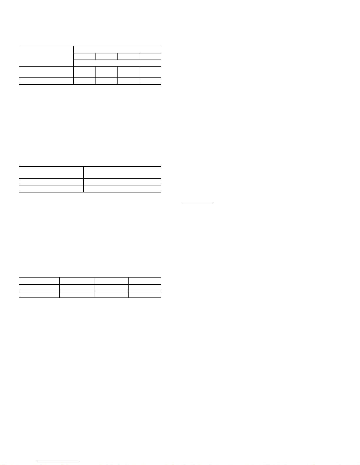
Table 11 — Dry-Coil Air Delivery* Cooling and Heat
Pump Heating; Sizes 048,060; Horizontal and
Vertical Discharge for Integrated Control
Motor Units at 230-V
(Deduct 10% from Cfm for 208-V Operation)
UNIT SIZE
48HX
EASY SELECT BOARD TERMINALS
1234
Airflow (Cfm)
048,060 Cooling Mode
048 Heating Mode
1260 1440 1575 1800
060 Heating Mode 1400 1600 1750 2000
*Air delivery values are for dry coil at 230 v.Airflow is independent of
external static pressure within 65% of table values up to
0.8 in wg.
NOTE: Do not operate the unit at a cooling airflow that is less than
350 cfm for each 12,000 Btuh of rated cooling capacity. Indoor-coil
icing may occur at airflows below this point. Water blow-off may occur at airflows above 450 cfm per 12,000 Btuh of rated cooling
capacity.
Table 12 — Dry Coil Air Delivery* Fan Only; Sizes
048,060; Horizontal and Vertical Discharge for
Integrated Control Motor Units at 230-V
(Deduct 10% from Cfm for 208-V Operation)
UNIT SIZE
48HX
FAN ONLY
AIRFLOW (Cfm)
048 1400
060 1750
*Air delivery values are for dry coil at 230 V.Airflow is independent of
external static pressure within 65% of table values up to
0.8 in. wg.
TYPE (ORN) — The TYPE is a preset factory default selection. The preset factory default setting is HPC for size
048 and HP for size 060. Default setting should not be
altered.
AC/HP CFM ADJUST (BLK) — The preset factory default
selection is MED. Selections HI and LO will adjust the airflow supplied for all operational modes (see table below).
The selection options allow installer to adjust airflow to meet
such individual needs as noise and static compensation, etc.
MODE FAN ONLY COOLING HEATING
LO — Adjust −15% −10% −10%
HI — Adjust 15% 10% 10%
OUTDOOR-AIR THERMOSTAT — The outdoor-air thermostat (OAT) is a field-adjustable control that controls the
temperature at which the 48HX unit changes from heat pump
operation to gas burner operation in first-stage heating. It adjusts temperatures from 0° to 52 F. (Second-stage heating is
always gas-fired heat.)
As outdoor temperatures decrease, the efficiency of heat
pumps decrease and a point is reached where gas heat becomes more economical than the heat pump. This point is
known as the economic balance point (EBP). At outdoor air
temperatures above the EBP,the 48HX unit operates the heat
pump on a call for first-stage heat and operates the gas burners on a call for second-stage heat. At temperatures below
the EBP, the OAT locks out the heat pump and operates the
gas burners for both the first- and second-stage heat.
The EBP is dependent on local utility rates. If the local
cost of electricity is high or the local cost of gas is low, it is
cost effective to switch to gas-fired heating at a warmer outdoor temperature.
Conversely, if the local cost of electricity is low or the
local cost of gas is high, it is cost effective to switch to gasfired heating at a colder outdoor temperature.
The OAT must be field set based on the local EBP. To
determine the EBP, first find the cost of gas on a $/Therm
basis and the cost of electricity on a $/kW basis. Refer to
Fig. 22, 48HX Economic Balance Point. On the horizontal
axis plot the cost of electricity and draw a vertical line from
this point. On the vertical axis plot the cost of gas and draw
a horizontal line until it intersects the vertical line. This intersection is the economic balance point and can be read directly by determining where the intersection falls in the set
of curves. This value will be in degrees Fahrenheit.
Once this value has been determined, the outdoor-air
thermostat can be set to provide for the most economical
operation.
EXAMPLE:
Cost of Electricity $ 0.1/kW
Cost of Gas $ 0.9/Therm
From Economic Balance Point Chart, Fig. 22, read that the
EBP is 30 F.
The EBP differs from the thermal balance point. The thermal balance point is the outdoor temperature below which
the heat pump can no longer satisfy the heating requirements of the building. The thermal balance point is determined by the thermal loss of the building and the size of the
heat pump. Unlike the EBP, no adjustment is necessary based
on the thermal balance point; the thermostat simply calls for
first-stage heat or second-stage heat as necessary.
To Set OAT — The OAT is located in the control box beneath the mounting bracket and is factory set at 40 F. Turn
knob on the OAT to the temperature that is equal to the EBP.
Refer to Fig. 22 and determine EBP as described previously.
Uncoil the OAT capillary and run it outside the unit to sense
outdoor temperature. The capillary may be supported by any
object outside the unit that does not get warm (such as the
incoming gas line) but must not rest on the unit itself. If the
outdoor air temperature is below the OAT setting, the cooling mode is locked out.
Sequence of Operation
HEATING SEQUENCE OF OPERATION — See wiring diagrams in back of book and unit wiring label.
On a call for heat, one of 2 Heating modes occurs, depending on the field setting of the economic balance point.
The first Heating mode occurs when the outdoor temperature is warmer than the EBP. On a call for heat, the thermostat makes circuits R-Y and R-G. When compressor time
delay (5 6 2 minutes) is completed, a circuit is made to C,
starting compressor (COMP) and outdoor-fan motor (OFM).
Circuit R-G also is completed, energizing indoor-fan relay
(IFR) and starting indoor-fan motor (IFM) after a 1-second
delay.Should room temperature continue to fall, circuit R-W
is made through second-stage thermostat bulb. One relay opens,
turning off the compressor, and another relay is energized
signaling the integrated gas control (IGC) board to bring on
the gas heat. When the thermostat is satisfied, contacts open,
deenergizing contactor and relay; motors and gas heater deenergize. The IFM may be controlled by a time-delay relay
that keeps the fan on for 30 seconds.
The second Heating mode occurs when the outdoor temperature is colder than the EBP. On a call for heat, the thermostat energizes the gas heat relay, signaling the IGC board
to bring on the gas heat. In this Heating mode, both firstand second-stage heat is gas heating. When thermostat is
22
Page 23
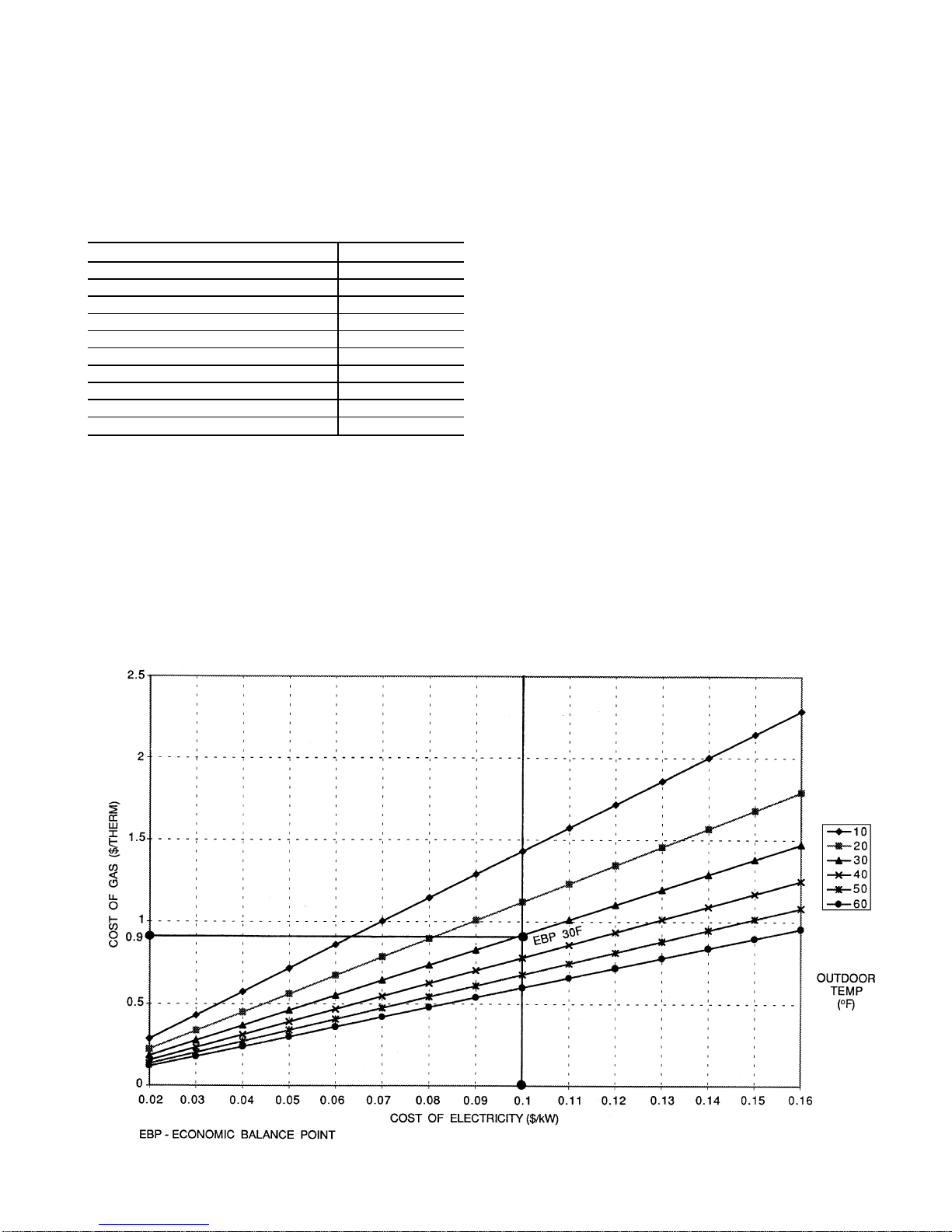
satisfied, contacts open, deenergizing contactor and relay;
motors and gas heater deenergize. The IFM may be controlled by a time-delay relay that keeps the fan on for
30 seconds.
An LED (light-emitting diode) indicator is provided on
the control board to monitor operation. The control board is
located by removing the burner access panel. During normal
operation, the LED is continuously on. See Table 13 for error codes.
See Fig. 23 for typical heat pump operation, heating mode.
Table 13 — LED Indications
ERROR CODE LED INDICATION
Normal Operation On
Hardware Failure Off
Fan On/Off Delay Modified 1 Flash
Limit Switch Fault 2 Flashes
Flame Sense Fault 3 Flashes
Four Consecutive Limit Switch Faults 4 Flashes
Ignition Lockout Fault 5 Flashes
Induced-Draft Motor Point 6 Flashes
Rollout Switch Fault 7 Flashes
Internal Control fault 8 Flashes
NOTES:
1. There is a 3-second pause between error code displays.
2. If more than one error code exists, all applicable error codes will
be displayed in numerical sequence.
3. This chart is on the wiring diagram located inside the burner ac-
cess panel.
COOLING SEQUENCE OF OPERATION — When the room
temperature rises to a point that is slightly above the cooling
control setting of the thermostat, the thermostat completes
the circuit between thermostat terminal R to terminals Y and
G. These completed circuits through the thermostat connect
contactor coil (C) (through unit wire Y) and blower relay
coil (BR) (through unit wire G) across the 24-v secondary of
transformer (TRAN).
NOTE: The blower relay coil (BR) is used on non-ICM
units; ICM units use evaporator (indoor) fan on (IFO)
connection.
The normally-open contacts of energizedcontactor (C) close
and complete the circuit through compressor motor (COMP)
to outdoor-fan motor (OFM). Both motors start instantly.
On non-ICM units, the set of normally-open contacts of
energized relay BR closes and completes the circuit through
blower (indoor) fan motor (IFM). On ICM units, the IFO
completes the circuit through IFM. The blower motor starts
instantly.
NOTE: Once the compressor has started and then has stopped,
it should not be started again until 5 minutes have elapsed.
The cooling cycle remains ‘‘on’’ until the room temperature drops to point that is slightly below the cooling
control setting of the room thermostat. At this point, the thermostat ‘‘breaks’’ the circuit between thermostat terminal R
to terminals Y and G. These open circuits deenergize contactor coil C and relay coil BR. The OFM and compressor
motor stop. After a 30-second delay, the IFM stops. The unit
is in a standby condition, waiting for the next call for cooling from the room thermostat.
See Fig. 24 for typical heat pump operation, cooling mode.
DEFROST — Defrost board (DB) is a time and temperature
control, which includes a field-selectable time period between checks for defrost (30, 50, and 90 minutes). Electronic timer and defrost cycle start only when contactor is
energized and defrost thermostat (DFT) is closed.
Defrost mode is identical to Cooling mode, except outdoorfan motor stops and gas heat turns on to warm air supplying
the conditioned space. Once the gas heat has been energized, it is locked in for a minimum of 1 minute.
Fig. 22 — 48HX Economic Balance Point
23
Page 24
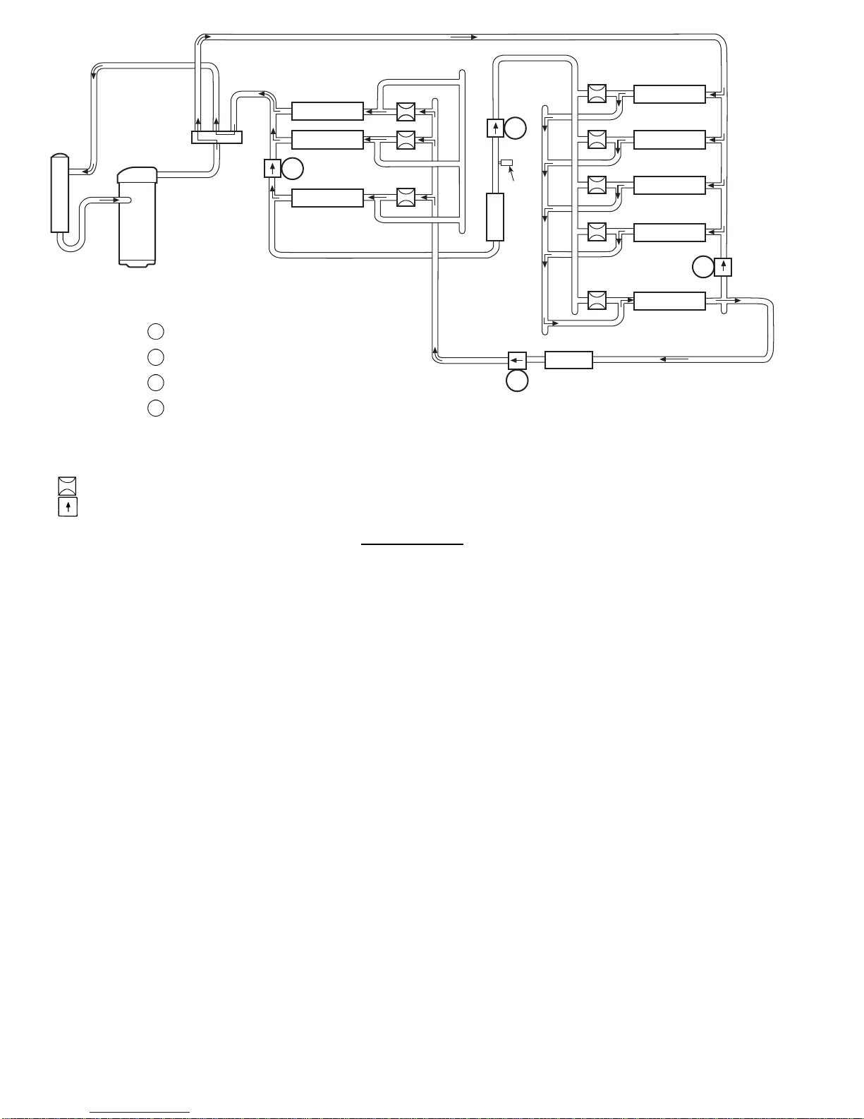
STRAINER
ACCUMULATOR
COMPRESSOR
STRAINER
LCS
OUTDOOR COIL
INDOOR COIL
A
B
D
C
Check Valves
A
Open
B
Closed
C
Open
D
Closed
LEGEND
LCS — Loss of Charge Switch
Acutrol™ Metering Device
Check Valve (Arrow indicates direction of flow)
HEATING CYCLE
1. Hot gas from compressor flows through the 4-way valve and is
directed to thecooling liquid line check valve. It is then condensed
and directed through subcooling circuits and out to the strainer
and the check valve in the heating liquid line.
2. The refrigerant then feeds the outdoor coil through the Acutrol
metering device on each circuit.
3. Each circuit evaporates the refrigerant and the circuits are combinedin the outdoor headerwith some ofthe circuits flowing through
the check valve.
4. The refrigerant then flows through the 4-way valve, accumulator,
and back to the compressor.
Fig. 23 — Typical Heat Pump Operation, Heating Mode
24
Page 25
STRAINER
ACCUMULATOR
COMPRESSOR
STRAINER
LCS
OUTDOOR COIL
INDOOR COIL
A
B
D
C
CheckValves
A
Closed
B
Open
C
Closed
D
Open
LEGEND
LCS — Loss of Charge Switch
Acutrol™ Metering Device
Check Valve (Arrow indicates direction of flow)
COOLING CYCLE
1. Hot gas from compressor flows through the 4-way valve and is
directed to the heating liquid line check valve. It is then condensedandsubcooledthrough converging circuits. Refrigerant leaves
the outdoor coil by way of the strainer and the check valve in the
cooling liquid line.
2. The refrigerant then feeds the indoor coil through the Acutrol
metering device on each circuit.
3. Each circuit evaporates the refrigerant and the circuits are combined in the indoor coil header with some of the circuits flowing
through the check valve.
4. The refrigerant then flows through the 4-way valve, accumulator,
and back to the compressor.
Fig. 24 — Typical Heat Pump Operation, Cooling Mode
25
Page 26
MAINTENANCE
To ensure continuing high performance, and to minimize
the possibility of premature equipment failure, periodic maintenance must be performed on this equipment. This dual fuel
heat pump should be inspected at least once each year by a
qualified service person. To troubleshoot heating or cooling
of units, refer to Troubleshooting tables at the back of the
book.
NOTE TO EQUIPMENT OWNER: Consult your local dealer
about the availability of a maintenance contract.
The ability to properly perform maintenance on this equipment requires certain expertise, mechanical skills, tools,
and equipment. If you do not possess these, do not attempt to perform any maintenance on this equipment
other than those procedures recommended in the
User’s Manual. FAILURE TO HEED THIS WARNING COULD RESULT IN SERIOUS PERSONAL
INJURY AND POSSIBLE DAMAGE TO THIS
EQUIPMENT.
The minimum maintenance requirements for this equipment are as follows:
1. Inspect air filter(s) each month. Clean or replace when
necessary.
2. Inspect indoor coil, drain pan, and condensate drain each
cooling season for cleanliness. Clean when necessary.
3. Inspect blower motor and wheel for cleanliness and check
lubrication each heating and cooling season. Clean and
lubricate (if required) when necessary. For first heating
season, inspect blower wheel bimonthly to determine proper
cleaning frequency.
4. Check electrical connections for tightness and controls
for proper operation each heating and cooling season. Service when necessary.
5. Check and inspect heating section before each heating sea-
son. Clean and adjust when necessary.
6. Check flue hood screen and remove any obstructions if
necessary.
7. Check vent screen and clean if necessary.
Failure to follow these warnings could result in serious
personal injury:
1. Turn off gas supply, then turn off electrical power to
the unit before performing any maintenance or service on the unit.
2. Use extreme caution when removing panels and parts.
As with any mechanical equipment, personal injury
can result from sharp edges, etc.
3. Never place anything combustible either on, or in contact with, the unit.
4. Should overheating occur, or the gas supply fail to
shut off, shut off the external main manual gas valve
to the unit, then shut off the electrical supply.
Air Filter
Never operate the unit without a suitable air filter in the
return-air duct system. Always replace the filter with the
same dimensional size and type as originally
installed. See Table 1 for recommended filter sizes.
Inspect air filter(s) at least once each month and replace
(throwaway-type) or clean (cleanable-type) at least twice during each heating and cooling season or whenever the
filter(s) becomes clogged with dust and lint.
Unit Top Removal
NOTE: When performing maintenance or service procedures that require removal of the unit top, be sure to perform
all of the routine maintenance procedures that require top
removal, including: inspection of the heat exchanger area,
coil inspection and cleaning, and condensate drain pan inspection and cleaning.
Only qualified service personnel should perform maintenance and service procedures that require unit top removal.
Refer to the following top removal procedures:
1. Turn off gas supply, then turn off electric power to unit.
2. Remove all screws that secure unit top, including screws
around 4 sides and those on top that screw into internal
divider panels. Save all screws.
3. Lift top from unit carefully. Set top on edge.
4. Carefully replace and secure unit top to unit, using screws
removed in Step 2, when maintenance and/or service procedures are completed. (Be sure to use original screws
that have rubber washers to seal out water when securing
top to internal divider panels.)
Indoor Blower and Motor
NOTE: Motors without oilers are prelubricated. Do not attempt to lubricate these motors.
For longer life, operating economy, and continuing efficiency, clean accumulated dirt and grease from the blower
wheel and motor annually.
Lubricate the motor every 5 years if the motor is used intermittently (thermostat FAN switch in AUTO. position), or
every 2 years if the motor is used continuously (thermostat
FAN switch in ON position).
Turn off the gas supply, then disconnect and tag electrical power to the unit before cleaning and lubricating
the blower motor and wheel. Failure to adhere to this
warning could cause personal injury or death.
To clean and lubricate the blower motor and wheel for
direct-drive models:
1. Remove and disassemble blower assembly as follows:
a. Remove blower access door.
b. On units without ICM, disconnectmotor lead from blower
relay (BR). Disconnect yellow lead from terminal L2
of the contactor.
c. On all units remove blower assembly from unit. Re-
move screws securing blower to gas partition and slide
assembly out. Be careful not to tear insulation in blower
compartment.
d. Ensure proper reassembly by marking blower wheel
and motor in relation to blower housing before disassembly.
e. Loosen setscrew(s) that secures wheel to motor shaft,
remove screws that secure motor mount brackets to
housing, and slide motor and motor mount out of
housing.
2. Lubricate motor as follows:
a. Thoroughly clean all accumulations of dirt or grease
from motor housing.
b. Remove dust caps or plugs from oil ports located at
each end of motor.
26
Page 27
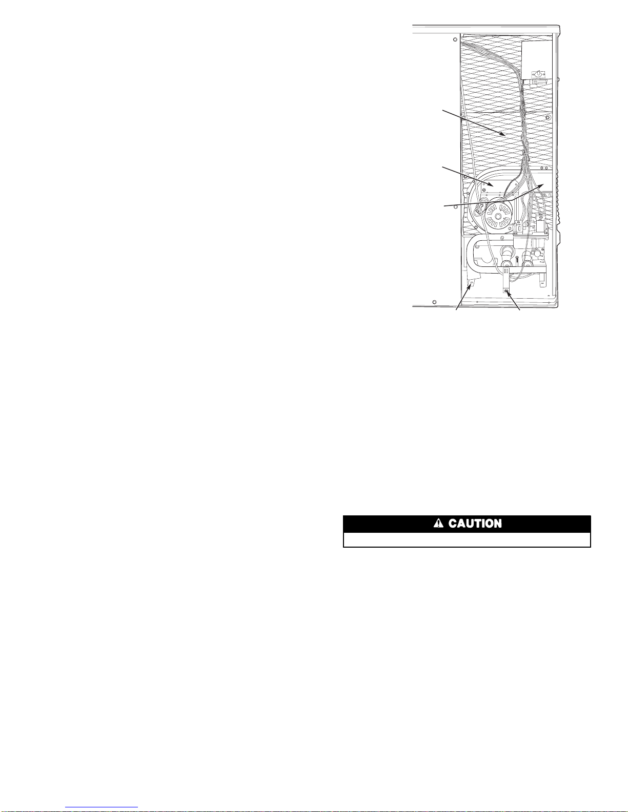
c. Use a good grade of SAE (Society of Automotive En-
gineers) 20 nondetergent motor oil and put one teaspoon (3⁄16oz. or 16 to 25 drops) in each oil port.
d. Allow time for oil to be absorbed by each bearing,
then wipe excess oil from motor housing.
e. Replace dust caps or plugs in oil ports.
3. Remove and clean blower wheel as follows:
a. Ensure proper reassembly by marking wheel
orientation.
b. Lift wheel from housing. When handling and/or clean-
ing blower wheel, be sure not to disturb balance weights
(clips) on blower wheel vanes.
c. Remove caked-on dirt from wheel and housing with a
brush. Remove lint and/or dirt accumulations from wheel
and housing with vacuum cleaner, using soft brush at-
tachment. Remove grease and oil with mild solvent.
d. Reassemble wheel into housing.
e. Reassemble motor into housing. Be sure setscrews are
tightened on motor shaft flats and not on round part of
shaft.
f. Reinstall blower access door.
4. Restore electrical power, then gas supply to unit. Start
unit and check for proper blower rotation and motor speeds
during heating and cooling cycles.
Flue Gas Passageways — To inspect the flue col-
lector box and upper areas of the heat exchanger:
1. Remove the combustion blower wheel and motor assembly according to directions in Combustion-Air Blower section below.
2. Remove the 3 screws holding the blower housing to the
flue collector box cover (see Fig. 25).
3. Remove the 12 screws holding the flue collector box cover
(Fig. 25) to the heat exchanger assembly. Inspect the heat
exchangers.
4. Clean all surfaces as required using the wire brush.
Combustion-Air Blower — Clean periodically to as-
sure proper airflow and heating efficiency. Inspect blower
wheel every fall and periodically during heating season. For
the first heating season, inspect blower wheel bimonthly to
determine proper cleaning frequency.
T oinspect blower wheel, remove draft hood assembly.Shine
a flashlight into opening to inspect wheel. If cleaning is required, remove motor and wheel as follows:
1. Remove burner access panel. (See Fig. 26.)
2. Remove the 7 screws that attach induced-draft motor mount-
ing plate to blower housing. (See Fig. 25.)
3. Slide the motor and blower wheel assembly out of the
blower housing. (See Fig. 27.) Clean the blower wheel.
If additional cleaning is required, continue with Steps 4
and 5.
4. To remove blower, remove 2 setscrews. (See Fig. 27.)
5. To remove motor, remove 4 screws that hold blower hous-
ing to mounting plate. Remove the motor cooling fan by
removing one setscrew. Remove nuts that hold motor to
mounting plate.
6. To reinstall, reverse the procedure outlined above.
Limit Switch — Remove blower panel. Limit switch is
located on the gas partition.
Burner Ignition — Unit is equipped with a direct spark
ignition 100% lockout system. Ignition module is located in the control box. Module contains a self-diagnostic
LED. During servicing, refer to Table 13 for LED
interpretation.
If lockout occurs, unit may be reset by either momentarily
interrupting power supply to unit, or turning selector switch
to OFF position at the thermostat.
Main Burners — At the beginning of each heating sea-
son, inspect for deterioration or blockage due to corrosion or
other causes. Observe the main burner flames and adjust if
necessary.
When servicing gas train, do not hit or plug orifice spuds.
REMOVAL OF GAS TRAIN
1. Shut off manual gas valve.
2. Shut off power to unit
3. Remove burner access panel. (See Fig. 26.)
4. Disconnect gas piping at unit gas valve.
5. Remove wires connected to gas valve. Mark each wire.
6. Remove ignitor and sensor wires at the ignitor module.
7. Remove the mounting screw that attaches the burner rack
to the basepan. (See Fig. 25.)
8. Slide the burner rack out of the unit. (See Fig. 25
and 28.)
9. To reinstall, reverse the procedure outlined above.
FLUE COLLECTOR
BOX (HIDDEN)
INDUCED
DRAFT MOTOR
MOUNTING PLATE
BLOWER HOUSING
BURNER
RACK
MOUNTING
SCREW
Fig. 25 — Blower Housing and Flue Collector Box
27
Page 28
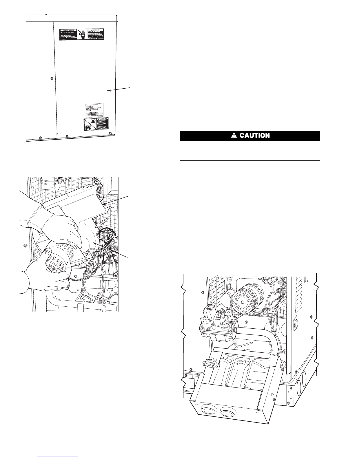
OutdoorCoil,IndoorCoil, and Condensate Drain
Pan —
Inspect the outdoor coil, indoor coil, and condensate drain pan at least once each year. Proper inspection and
cleaning requires the removal of the unit top. See Unit Top
Removal section on page 26.
The coils are easily cleaned when dry; therefore, inspect
and clean the coils either before or after each cooling season. Remove all obstructions, including weeds and shrubs,
that interfere with the airflow through the outdoor coil.
Straighten bent fins with a fin comb. If coated with dirt or
lint, clean the coils with a vacuum cleaner, using the soft
brush attachment. Be careful not to bend the fins. If coated
with oil or grease, clean the coils with a mild detergent-andwater solution. Rinse coils with clear water, using a garden
hose. Be careful not to splash water on motors, insulation,
wiring, or air filter(s). For best results, spray outdoor coil
fins from inside to outside the unit. Be sure to clean between
outer and inner sections of outdoor coil. Be sure to flush all
dirt and debris from the unit base.
Inspect the drain pan and condensate drain line when inspecting the coils. Clean the drain pan and condensate drain
by removing all foreign matter from the pan. Flush the pan
and drain tube with clear water. Do not splash water on the
insulation, motor, wiring, or air filter(s). If the drain tube is
restricted, clear it with a ‘‘plumbers snake’’or similar probe
device. Ensure that the auxiliary drain port above the drain
tube is also clear.
Outdoor Fan
Keep the outdoor fan free from all obstructions to ensure proper cooling operation. Never place articles on
top of the unit. Damage to unit may result.
1. Remove 2 screws at bottom and 2 screws along sides of
condenser air intake grille and remove plastic grille.
2. Inspect the fan blades for cracks or bends.
3. If fan needs to be removed, loosen the setscrew and slide
the fan off the motor shaft.
4. When replacing fan blade, position blade so that lead-
ing edge is
1
⁄2in. in front of fan orifice. See Fig. 19.
5. Ensure that setscrew engages the flat area on the motor
shaft when tightening.
6. Replace grille.
BURNER
ACCESS
PANEL
Fig. 26 — Burner Access Panel
BLOWER
HOUSING
2 SETSCREWS
(HIDDEN)
Fig. 27 — Removal of Motor and Blower Wheel
Fig. 28 — Burner Rack Removed
28
Page 29

Electrical Controls and Wiring— Inspect and check
the electrical controls and wiring annually. Be sure to turn
off the gas supply, and then the electrical power to the unit.
Remove the control, blower, and compressor compartment access panels to locate all the electrical controls and
wiring. Check all electrical connections for tightness. Tighten
all screw connections. If any smoky or burned connections
are noticed, disassemble the connection, clean all the parts,
restrip the wire end and reassemble the connection properly
and securely.
After inspecting the electrical controls and wiring, replace all the panels. Start the unit, and observe at least one
complete heating cycle and one complete cooling cycle to
ensure proper operation. If discrepancies are observed in either or both operating cycles, or if a suspected malfunction
has occurred, check each electrical component with the proper
electrical instrumentation. Refer to the unit wiring label when
making these checkouts.
NOTE: Refer to the heating and/or cooling sequence of operation in this publication as an aid in determining proper
control operation.
RefrigerantCircuit— Inspect all refrigerant tubing con-
nections and the unit base for oil accumulations annually.
Detecting oil generally indicates a refrigerant leak.
If oil is detected or if low cooling performance is suspected, leak-test all refrigerant tubing using an electronic
leak-detector, halide torch, or liquid-soap solution. If a
refrigerant leak is detected, refer to Check for Refrigerant
Leaks section on page 15.
If no refrigerant leaks are found and low cooling performance is suspected, refer to Checking and Adjusting
Refrigerant Charge section on page 18.
Gas Input — The gas input does not require checking
unless improper heating performance is suspected. If a problem exists, refer to Start-Up section on page 15.
Indoor Airflow — The heating and/or cooling airflow
does not require checking unless improper performance is
suspected. If a problem exists, be sure that all supply- and
return-air grilles are open and free from obstructions, and
that the air filter is clean. When necessary, refer to Indoor
Airflow andAirflowAdjustments section on page 20 to check
the system airflow.
Metering Device —Acutrol™ Device — This me-
tering device is a fixed orifice and is located in the header to
the indoor and outdoor coils.
Liquid LineStrainer— The liquid line strainer (to pro-
tect metering device) is made of wire mesh and located in
the liquid line on the inlet side of the metering device.
29
Page 30
TROUBLESHOOTING
Cooling and Heating
SYMPTOM CAUSE REMEDY
Compressor and outdoor fan will not start.
OAT set above outdoor ambient temperature Lower OAT setting.
Power failure Call power company.
Fuse blown or circuit breaker tripped Replace fuse or reset circuit breaker.
Defective thermostat, contactor, transformer,
control relay, or defrost board
Replace component.
Insufficient line voltage Determine cause and correct.
Incorrect or faulty wiring Check wiring diagram and rewire correctly.
Thermostat setting too high Lower thermostat setting below room temperature.
Units have a 5-minute time delay DO NOT bypass this compressor time delay — wait
for 5 minutes until time-delay relay is deenergized.
Compressor will not
start but outdoor fan
runs.
Faulty wiring or loose connections in
compressor circuit
Check wiring and repair or replace.
Compressor motor burned out, seized, or
internal overload open
Determine cause. Replace compressor.
Defective run capacitor or overload Determine cause and replace.
One leg of 3-phase power dead Replace fuse or reset circuit breaker.
Determine cause.
Low input voltage (20% low) Determine cause and correct.
Three-phase scroll
compressor makes
excessive noise, and
there may be a low
pressure differential
Scroll compressor is rotating in the
wrong direction
Correct the direction of rotation by reversing the
3-phase power leads to the unit. Shut down unit
to allow pressures to equalize.
Compressor cycles
(other than normally
satisfying thermostat).
Refrigerant overcharge or undercharge Recover refrigerant, evacuate system, and recharge
to capacities shown on nameplate.
Defective compressor Replace and determine cause.
Insufficient line voltage Determine cause and correct.
Blocked condenser coil Determine cause and correct.
Defective run/start capacitor, overload,
or start relay
Determine cause and replace.
Defective thermostat Replace thermostat.
Faulty condenser-fan motor or capacitor Replace.
Damaged reversing valve Determine cause and correct.
Restriction in refrigerant system Locate restriction and remove.
Compressor operates
continuously.
Dirty air filter Replace filter.
Unit undersized for load Decrease load or increase unit size.
Thermostat set too low Reset thermostat.
Low refrigerant charge Locate leak, repair, and recharge.
Leaking valves in compressor Replace compressor.
Frosted coil with incorrect defrost operation Check defrost time settings. Reset as necessary.
Check defrost temperature switch. Replace as necessary.
Air in system Recover refrigerant, evacuate system, and recharge.
Outdoor coil dirty or restricted Clean coil or remove restriction.
Excessive head
pressure.
Dirty air filter Replace filter.
Dirty condenser coil Clean coil.
Refrigerant overcharged Recover excess refrigerant.
Air in system Recover refrigerant, evacuate system, and recharge.
(Heat) Indoor air restricted or recirculating Determine cause and correct.
Indoor or outdoor air restricted or
air short-cycling
Determine cause and correct.
Head pressure too low. Low refrigerant charge Check for leaks, repair and recharge.
Compressor valves leaking Replace compressor.
Restriction in liquid tube Remove restriction.
LEGEND
OAT — Outdoor Air Thermostat
30
Page 31
Cooling and Heating (cont)
SYMPTOM CAUSE REMEDY
Excessive suction
pressure.
(Cool) High heat load Check for source and eliminate.
Reversing valve hung up or leaking internally Replace valve.
Refrigerant overcharged Recover excess refrigerant.
Suction pressure too
low.
(Cool) Dirty air filter Replace filter.
(Heat) Outdoor coil frosted Move timer on control board to 30 minutes
between defrost cycles.
Low refrigerant charge Check for leaks, repair and recharge.
Metering device or low side restricted Remove source of restriction.
(Cool) Insufficient coil airflow Increase air quantity. Check filter — replace if
necessary.
(Cool) Temperature too low in conditioned area Reset thermostat.
(Cool) Outdoor ambient below 40 F Install low-ambient kit.
Field-installed filter-drier restricted Replace.
Compressor runs but
outdoor fan does not.
NC (normally closed) contacts on defrost board
open
Check condition of relay on board. Replace if
necessary.
Integrated control
motor (sizes 048 and
060) IFM does not run.
Motor overload open Check motor temeprature.
Replace motor or capacitor.
Blower wheel not secured to shaft Properly tighten blower wheel to shaft.
Insufficient voltage at motor Determine cause and correct.
Power connectors not properly seated Connectors should snap easily; do not force.
Integrated control
motor (sizes 048 and
060) IFM runs when it
should be off.
Motor programmed with a delay profile Allow a few minutes for motor to shut off.
With thermostat in off state, the voltage on
G,Y1,Y,Y2,W with respect to common, should be
1
⁄2of actual low voltage supply
If measured voltage is more than
1
⁄2, the thermostat is incompatible with motor. If voltage is less
than
1
⁄2, the motor has failed.
Integrated control
motor (sizes 048 and
060) IFM operation is
intermittent.
Water dripping into motor Verify proper drip loops in connector wires.
Connectors not firmly seated Gently pull wires individually to be sure they are
crimped into the housing.
LEGEND
IFM — Indoor Fan Motor
Gas Heating
SYMPTOM CAUSE REMEDY
Burners will not ignite. Water in gas line Drain. Install drip leg.
No power to furnace Check power supply fuses, wiring, or circuit breaker.
No 24-v power supply to control
circuit
Check transformer.
NOTE: Some transformers have internal overcurrent
protection that requires a cool-down period to reset.
Miswired or loose connections Check all wiring and wirenut connections.
Burned-out heat anticipator in
thermostat
Replace thermostat.
Broken thermostat wire Run continuity check. Replace wire if necessary.
Misaligned spark electrodes Check flame ignition and sense electrode positioning.
Adjust as necessary.
No gas at main burners 1. Check gas line for air. Purge as necessary.
NOTE: After purging gas line of air, wait at least
5 minutes for any gas to dissipate before attempting
to light unit.
2. Check gas valve.
Inadequate heating. Dirty air filter Clean or replace filter as necessary.
Gas input to furnace too low Check gas pressure at manifold. Match with that on
unit nameplate.
Unit undersized for application Replace with proper unit or add additional unit.
Restricted airflow Clean or replace filter. Remove any restriction.
Blower speed too low Use faster speed tap if available, or install alternate
motor.
Limit switch cycles main burners Check rotation of blower, thermostat heat anticipator
settings, temperature rise of unit. Adjust as necessary.
Poor flame characteristics. Incomplete combustion results in:
Aldehyde odors, carbon monoxide, sooting flame, floating flame
1. Tighten all screws around burner compartment.
2. Cracked heat exchanger. Replace.
3. Unit overfired. Reduce input (change orifices or
adjust gas line or manifold pressure).
4. Check burner alignment.
31
Page 32
LED Troubleshooting — Error Code
SYMPTOM CAUSE REMEDY
Hardware failure.
(LED OFF)
Loss of power to control module
(IGC).
Check 5 amp fuse on IGC, power to unit, 24-v circuit
breaker, and transformer. Units without a 24-v circuit
breaker have an internal overload in the 24-v transformer. If
the overload trips, allow 10 minutes for automatic reset.
Limit switch fault.
(LED 2 flashes)
High temperature limit switch is open. Check the operation of the indoor-fan motor. Ensure that
the supply-air temperature rise is in accordance with the
range on the unit nameplate.
Flame sense fault.
(LED 3 flashes)
The IGC sensed flame that should not
be present.
Reset unit. If problem persists, replace control board.
4 consecutive limit switch
trips.
(LED 4 flashes)
Inadequate airflow to unit. Check operation of indoor-fan motor and that supply-air
temperature rise agrees with range on unit nameplate
information.
Ignition lockout.
(LED 5 flashes)
Unit unsuccessfully attempted ignition
for 15 minutes.
Check ignitor and flame sensor electrode spacing, gaps,
etc. Ensure that flame sense and ignition wires are properly
terminated. Verify that unit is obtaining proper amount of
gas.
Induced-draft motor fault.
(LED 6 flashes)
IGC does not sense that induced-draft
motor is operating.
Check for proper voltage. If motor is operating, check the
speed sensor plug/IGC Terminal J2 connection. Proper
connection:
PIN 1 — White, PIN 2 — Red, PIN 3 — Black.
Rollout switch fault.
(LED 7 flashes)
Rollout switch has opened. Rollout switch will automatically reset, but IGC will continue
to lockout unit. Check gas valve operation. Ensure that
induced-draft blower wheel is properly secured to motor
shaft. Reset unit at unit disconnect.
Internal control fault.
(LED 8 flashes)
Microprocessor has sensed an error
in the software or hardware.
If error code is not cleared by resetting unit power, replace
the IGC.
If the IGC must be replaced, be sure to ground yourself to
dissipate any electrical charge that may be present before
handling new control board. The IGC is sensitive to static electricity and may be damaged if the necessary precautions are
not taken.
IMPORTANT: Refer to Troubleshooting, Heating chart for additional troubleshooting analysis.
LEGEND
IGC — Integrated Gas Unit Controller
LED — Light-Emitting Diode
32
Page 33

Page 34

Copyright 1998 Carrier Corporation
Manufacturer reserves the right to discontinue, or change at any time, specifications or designs without notice and without incurring obligations.
Book 1 4
Tab 5a 5a
PC 111 Catalog No. 534-722 Printed in U.S.A. Form 48HX-3SI Pg 34 9-98 Replaces: 48HX-2SI
Page 35

Page 36
START-UP CHECKLIST
(Remove and Store in Job File)
I. PRELIMINARY INFORMATION
MODEL NO.:
DATE:
SERIAL NO.:
TECHNICIAN:
II. PRE-START-UP (insert checkmark in box as each item is completed)
M VERIFY THAT ALL PACKING MATERIALS HAVE BEEN REMOVED FROM UNIT
M VERIFY THAT CONDENSATE CONNECTION IS INSTALLED PER INSTALLATION INSTRUCTIONS
M CHECK ALL ELECTRICAL CONNECTIONS AND TERMINALS FOR TIGHTNESS
M CHECK GAS PIPING FOR LEAKS
M CHECK THAT INDOOR AIR FILTER IS CLEAN AND IN PLACE
M VERIFY THAT UNIT INSTALLATION IS LEVEL
M CHECK FAN WHEEL AND PROPELLER FOR LOCATION IN HOUSING/ORIFICE AND SETSCREW
TIGHTNESS
M SET OUTDOOR-AIR THERMOSTAT (OAT) TO SELECTION BASED ON ECONOMIC BALANCE
POINT (EBP). SEE PAGE 22.
III. START-UP
ELECTRICAL
SUPPLY VOLTAGE L1-L2
L2-L3 L3-L1
COMPRESSOR AMPS L1 L2 L3
COMPRESSOR AMPS L1 L2 L3
INDOOR FAN AMPS
TEMPERATURES
OUTDOOR-AIR TEMPERATURE
DB
RETURN-AIR TEMPERATURE
DB WB
COOLING SUPPLY AIR
GAS HEAT SUPPLY AIR
PRESSURES
GAS INLET PRESSURE
IN. WG
GAS MANIFOLD PRESSURE
IN. WG
REFRIGERANT SUCTION
PSIG
REFRIGERANT DISCHARGE
PSIG
M VERIFY REFRIGERANT CHARGE USING CHARGING TABLES
M VERIFY THAT 3-PHASE SCROLL COMPRESSOR IS ROTATING IN CORRECT DIRECTION
----------------------------------------------------------------------------------------
CUT ALONG DOTTED LINE CUT ALONG DOTTED LINE
Copyright 1998 Carrier Corporation
Manufacturer reserves the right to discontinue, or change at any time, specifications or designs without notice and without incurring obligations.
Book 1 4
Tab 5a 5a
PC 111 Catalog No. 534-722 Printed in U.S.A. Form 48HX-3SI CL-1 9-98 Replaces: 48HX-2SI
 Loading...