

Page 1
Installation Instructions
CONTENTS
Page
SAFETY CONSIDERATIONS ...................1
INSTALLATION .............................1-12
Step 1 — Provide Unit Support ...............1
• ROOF CURB
• ALTERNATE UNIT SUPPORT
Step 2 — Rig and Place Unit ..................3
• POSITIONING
• ROOF MOUNT
Step 3 — Field Fabricate Ductwork ............7
Step 4 — Make Unit Duct Connections ........7
Step 5 — Install Flue Hood ...................7
Step6—TrapCondensate Drain .............8
Step 7 — Install Gas Piping ...................8
Step 8 — Make Electrical Connections ........9
• FIELD POWER SUPPLY
• FIELD CONTROL WIRING
Step 9 — Make Outdoor-Air Inlet
Adjustments ...............................10
• MANUAL OUTDOOR-AIR DAMPER
• OPTIONAL FACTORY-INSTALLED
ECONOMIZER
Step 10 — Install Outdoor-Air Hood ..........10
START-UP ................................12-17
SERVICE ..................................18-27
START-UP CHECKLIST .....................CL-1
48HJ015-025
Single Package Rooftop Units
Electric Cooling/Gas Heating
1. Improper installation, adjustment, alteration, service, or maintenance can cause property damage, personal injury, or loss of life. Refer to the User’s Information Manual provided with this unit for more
details.
2. Do not store or use gasoline or other flammable vapors and liquids in the vicinity of this or any other
appliance.
What to do if you smell gas:
1. DO NOT try to light any appliance.
2. DO NOT touch any electrical switch, or use any phone
in your building.
3. IMMEDIATELY call your gas supplier from a neighbor’s phone. Follow the gas supplier’s instructions.
4. If you cannot reach your gas supplier, call the fire
department.
Disconnect gas piping from unit when pressure testing
at pressure greater than 0.5 psig. Pressures greater than
0.5 psig will cause gas valve damage resulting in haz-
ardous condition. If gas valve is subjected to pressure
greater than 0.5 psig, it must be replaced before use. When
pressure testing field-supplied gas piping at pressures of
0.5 psig or less, a unit connected to such piping must be
isolated by closing the manual gas valve(s).
SAFETY CONSIDERATIONS
Installation and servicing of air-conditioning equipment
can be hazardous due to system pressure and electrical components. Only trained andqualified service personnel should
install, repair, or service air-conditioning equipment.
Untrained personnel can perform the basic maintenance
functions of cleaning coils and filters and replacing filters.
All other operations should be performed by trained service
personnel. When working on air-conditioning equipment, observe precautions in the literature, tags and labels attached
to the unit, and other safety precautions that may apply.
Follow all safety codes.W earsafetyglasses and work gloves.
Use quenching cloth for unbrazing operations. Have fire extinguishers available for all brazing operations.
Before performing service or maintenance operations on
unit, turn offmain power switch to unit. Electrical shock
could cause personal injury.
Manufacturer reserves the right to discontinue, or change at any time, specifications or designs without notice and without incurring obligations.
Book 1
Tab 1a
PC 111 Catalog No. 534-807 Printed in U.S.A. Form 48HJ-9SI Pg 1 2-95 Replaces: 48HJ-5SI
Step 1 — Provide Unit Support
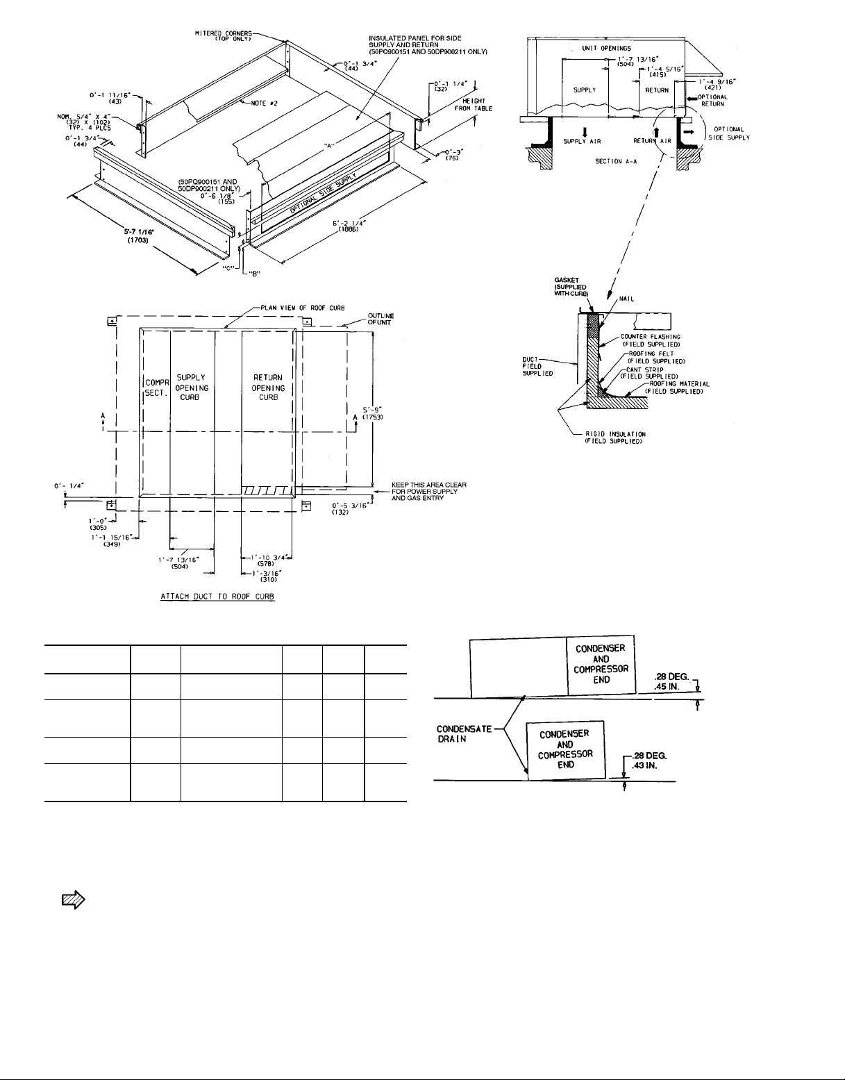
ROOF CURB — Assemble or install accessory roof curb in
accordance with instructions shipped with this accessory. See
Fig. 1 and 2. Install insulation, cant strips, roofing, and counter
flashing as shown. Ductwork can be installed to roof curb
before unit is set in place. Curb should be level. This is necessary to permit unit drain to function properly. Unit leveling tolerance is ±1⁄16in. per linear ft in any direction. Refer
to Accessory Roof Curb Installation Instructions for additional information as required. When accessory roof curb is
used, unit may be installed on class A, B, or C roof covering
material.
IMPORTANT: The gasketing of the unit to the roof
curb is critical for a watertight seal. Install gasket with
the roof curb as shown in Fig. 1. Improperly applied
gasket can also result in air leaks and poor unit
performance.
INSTALLATION
Instructions continued on page 3.
Page 2
ACCESSORY
PACKAGE NO.
50PQ900221
50PQ900141
50PQ900151
50DP900211
CURB
HEIGHT
18-29
(305)
28-09
(610)
28-09
(610)
18-119
(584)
DESCRIPTION ‘‘A’’ ‘‘B’’ ‘‘C’’
Standard Curb —
149 High
Standard Curb
for Units Requiring
High Installation
Horizontal Supply
and Return Curb
Pre-Assembled,
High-Static,
Horizontal Adapter
LEGEND
COMP SECT. — Compressor Section
NOTES:
1. Roof curb accessory is shipped unassembled.
2. Insulated panels,
3. Dimensions in ( ) are in millimeters.
1
⁄2-in. thick neoprene-coated, 2 lb density.
4. Direction of airflow.
5. Roof curb: 18 gage steel.
6. Attach all ductwork to roof curb.
7. Field installation of sidewall is mandatory.
Fig. 1 — Roof Curb and Horizontal Adapter Details
———
———
08-2
(64)
08-6
(159)
1
⁄
2
9
18-69
(457)
1
⁄
4
9
18-25⁄
(371)
58-69
(1676)
68-29
(1880)
8
9
NOTE: To prevent the hazard of stagnant water build-up in the drain
pan of the indoor-air section, unit can only be pitched as shown.
2
Page 3
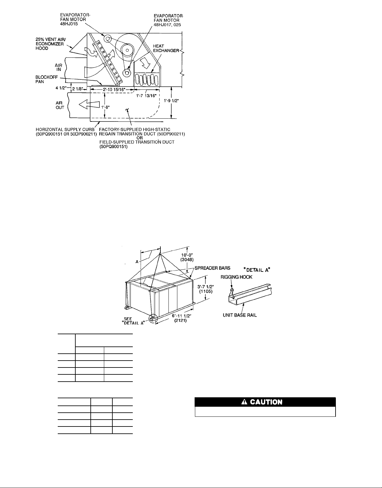
Fig. 2 — Horizontal Supply/Return Curb
and Horizontal Adapter Details
ALTERNATE UNIT SUPPORT — When the curb cannot
be used, install unit on a noncombustible surface. Support
unit with sleepers, using unit curb support area. If sleepers
cannot be used, support long sides of unit with a minimum
of 3 equally spaced 4-in. x 4-in. pads on each side.
Step2 — Rig and Place Unit — Inspect unit for trans-
portation damage. File any claim with transportation agency.
Do not drop unit; keep upright. Use spreader bars over
unit to prevent sling or cable damage. Rollers may be used
to move unit across a roof. Level by using unit frame as a
reference; leveling tolerance is ±
1
⁄16in. per linear ft in any
direction. See Fig. 3 for additional information. Unit operating weight is shown in Table 1.
Four lifting holes are provided in ends of unit base rails
as shown in Fig. 3. Refer to rigging instructions on unit.
POSITIONING — Maintain clearance, per Fig. 4 and 5, around
and above unit to provide minimum distance from combustible materials, proper airflow, and service access.
Do not install unit in an indoor location. Do not locate
unit air inlets near exhaust vents or other sources of contaminated air. For proper unit operation, adequate combustion and ventilation air must be provided in accordance with
Section 5.3 (Air for Combustion and Ventilation) of the
National Fuel Gas Code, ANSI Z223.1 (American National
Standards Institute).
Although unit is weatherproof, guard against water from
higher level runoff and overhangs.
Locate mechanical draft system flue assembly at least
4 ft from any opening through which combustion products
could enter the building, and at least 4 ft from any adjacent
building. When unit is located adjacent to public walkways,
flue assembly must be at least 7 ft above grade.
ROOF MOUNT — Check building codes for weight distribution requirements. Unit weight is shown in Table 1.
Instructions continued on page 7.
MAXIMUM SHIPPING
UNIT
48HJ
D015 1920 871
E015 1940 880
E017 2310 1048
D025 2535 1150
WEIGHT
Lb Kg
Dimension A
UNIT Ft-in. mm
48HJD015 3-1
48HJE015 3-1
48HJE017 3-4
48HJD025 3-4
3
⁄
8
1
⁄
4
3
⁄41035
3
⁄41010
949
946
NOTES:
1. Dimensions in ( ) are in millimeters.
2. Refer to Table 1 for unit operating weights.
3. Remove boards at ends of unit and runners prior to rigging.
4. Rig by inserting hooks into unit base rails as shown. Use corner
postfrompackaging to protect coil fromdamage.Usebumper boards
for spreader bars.
5. Weights do not include optional economizer.See Table1 for economizer weight.
6. Weights given are for aluminum evaporator coil plate fins and copper condenser coil plate fins. Weights of other metal combinations
are listed in Table 1.
All panels must be in place when rigging.
Fig. 3 — Rigging Details
3
Page 4

Table 1 — Physical Data
UNIT SIZE 48
OPERATING WT (lb)
COMPRESSOR 06D Semi-Hermetic
REFRIGERANT TYPE R-22
CONDENSER COIL Copper Tubes, Aluminum or Copper Plate Fins
CONDENSER FAN Propeller Type, Direct Drive
EVAPORATOR COIL Copper Tubes, Aluminum or Copper Plate Fins
EVAPORATOR FAN Centrifugal, Adjustable Pitch Belt Drive
FURNACE SECTION
HIGH-PRESSURE SWITCH
LOW-PRESSURE SWITCH
Al/Al* 1640/1660 2010 2235
Unit Al/Cu* 1770/1790 2160 2385
Cu/Cu* 1840/1860 2250 2515
Economizer 110 110 110
Roof Curb† 200 200 200
Number 122
Cylinders 646
Charge (lb)
System 1 22.50 14.25 17.50
System 2 — 15.00 17.00
Rows 344
Fins/in. 15 15 15
Total Face Area (sq ft) 22.2 22.2 22.2
Nominal Cfm 10,500 10,500 14,200
Number...Diameter (in.) 3...22 3...22 2...30
Motor Hp (1075 Rpm)
Watts Input (Total) 1090 1090 3400
Rows 234
Fins/in. 17 15 15
Total Face Area (sq ft) 17.9 17.9 17.9
Quantity...Size (in.) 2...10 x 10 2...10 x 10 2...12 x 12 2...12 x12
Nominal Cfm 5000 5000 6000 8000
Fan Rpm Range 1194-1526 1201-1462 1238-1494 1323-1579
Maximum Allowable Rpm 1550 1550 1550 1550
Motor Pulley Pitch Diameter (in.) 3.4/4.4 4.3/5.3 5.4/6.6 5.8/7.0
Fan Pulley Pitch Diameter (in.) 5.2 6.4 7.9 7.9
Belt, Quantity...Type...Length (in.) 1...AX...42 1...B...45 1...BX...50 1...BX...51
Factory Speed Setting (Rpm) 1293 1279 1366 1451
Motor Hp (Service Factor) 3.7 (1.15) 3 (1.15) 5 (1.15) 10 (1.15)
Motor Frame Size 56H 56H 184T 215T
Rollout Switch Cutout Temp (F)** 190 190 190
Burner Orifice Diameter (in. ...drill size)
Natural Gas
Pilot Orifice Diameter (Quantity) in. ...drill size
Natural Gas
Thermostat Heat Anticipator Setting
Stage 1
Stage 2
Gas Valve Quantity 1/2 2 2
Cutout (psig) 426
Reset (psig) 320
Cutout (psig) 7
Reset (psig) 22
208/230, 460 V 575 V
AIR INLET SCREENS Cleanable
Economizer, Quantity...Size (in.)
RETURN-AIR FILTERS (TYPE) 10% Efficient — 2-in. Throwaway Fiberglass
Quantity... Size (in.)
HJD015/HJE015
1
⁄
2
HJE017 HJD025
1
⁄
2
.113...33 .113...33 .113...33
(1) .055...54/
(1) .055...54
(1) .041...59
1.2/1.2
—/0.6
2...20 x 25 x 1
1...20 x 20 x 1
4...20 x 20 x 2
4...16 x 20 x 2
(1) .055...54
(1) .041...59
1.2
0.6
1...1075
(1) .055...54
(1) .041...59
1.2
0.6
LEGEND
Al — Aluminum
Cu — Copper
*Evaporator coil fin material/condenser coil fin material.
†Weight of 14 in. roof curb.
**Rollout switch is manual reset.
4
Page 5
UNIT
48HJ
MAXIMUM SHIPPING WEIGHT
Lb Kg
D015 1920 871
E015 1940 880
E017 2310 1048
UNIT
48HJ
Ft-in. mm Ft-in. mm
DIMENSIONS
XY
D015 3-2 965 4-0 1219
UNIT
48HJ
E015 3-2 965 4-0 1219
E017 3-7
ABCD
Lb Kg Lb Kg Lb Kg Lb Kg
3
⁄
8
1102 3-65⁄
WEIGHT OF CORNER*
8
D015 365 166 360 163 373 169 540 245
E015 372 169 363 165 377 171 547 248
E017 509 231 506 230 475 216 519 235
*Weights are for unit only and do not include options or crating.
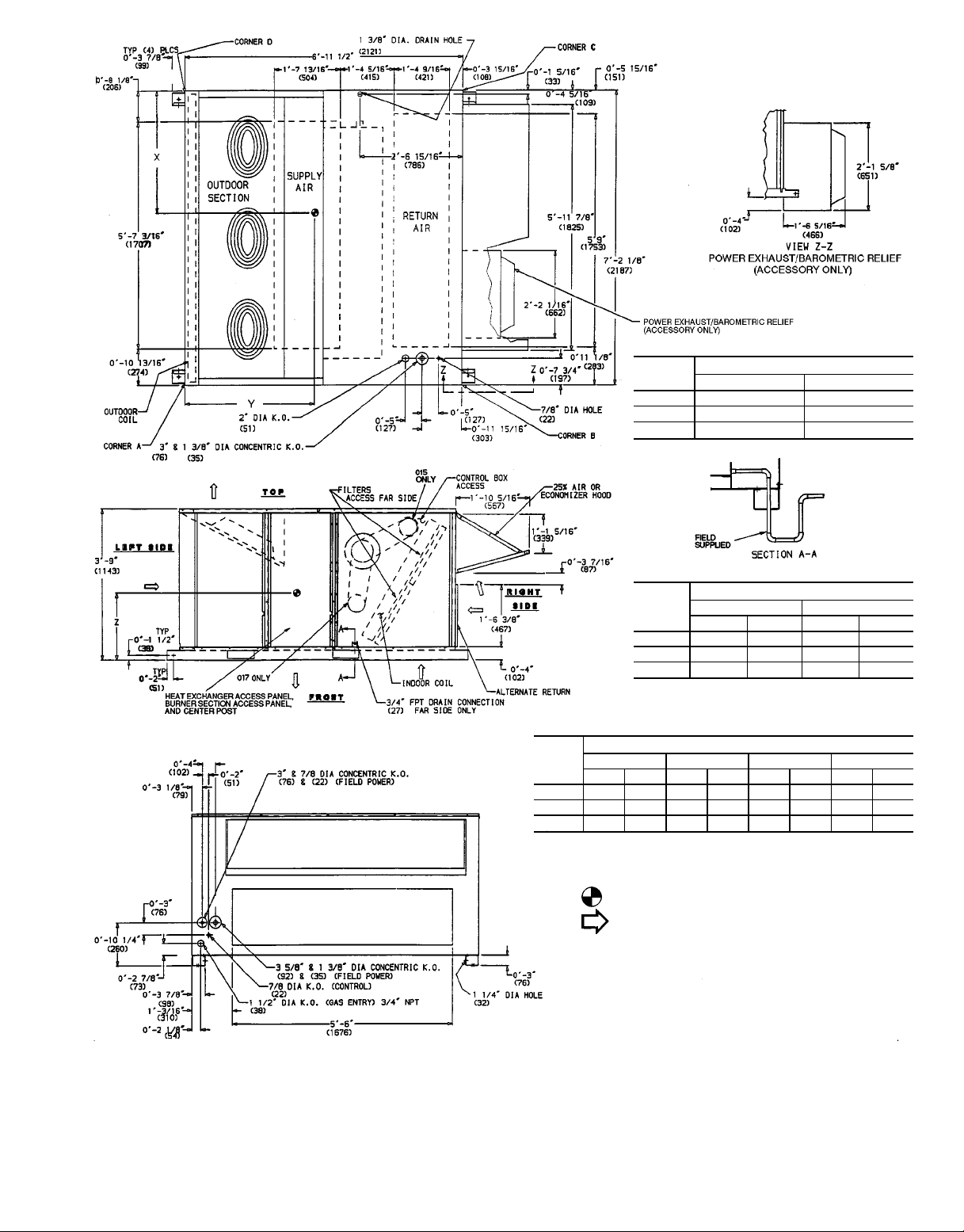
NOTES:
1. Dimensions in ( ) are in millimeters.
2. Center of gravity.
3. Direction of airflow.
4. Ductwork to be attached to accessory roof curb only.
5. Minimum clearance:
a. Rear: 78-09 (2134)for coil removal. This dimension can bereduced
to 48-09 (1219) if conditions permit coil removal from the top.
b. Left side: 48-09 (1219) for proper condenser coil airflow.
c. Front: 48-09 (1219) for control box access.
d. Right side: 48-09 (1219) for proper operation of damper and power
exhaust (if so equipped).
e. Top: 68-09 (1829) to assure proper condenser fan operation.
f. Local codes or jurisdiction may prevail.
6. Withtheexception of clearance forthe condenser coil andthe damper/
power exhaust as stated in Note No. 5, a removable fence or barricade requires no clearance.
7. Dimensions are from outside of corner post. Allow 08side for top cover drip edge.
5
⁄169 (8) on each
1083
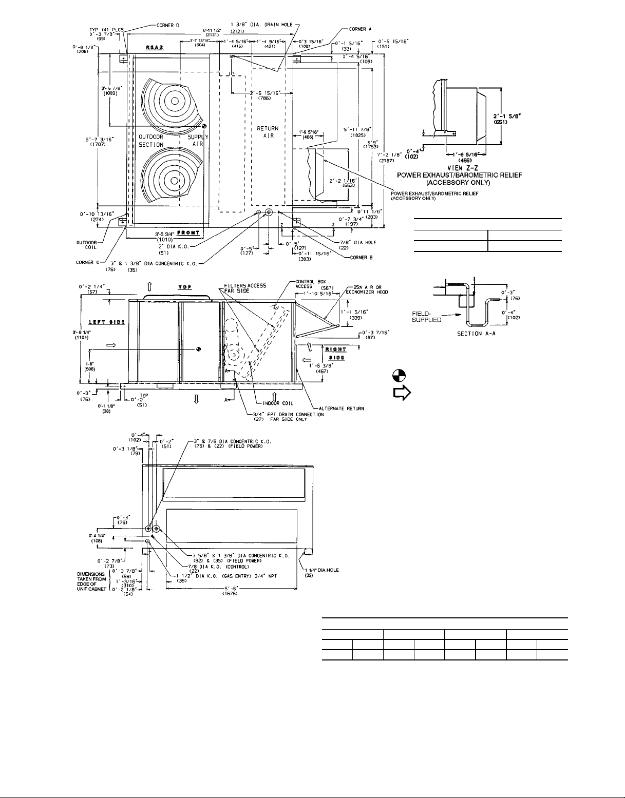
Fig. 4 — Base Unit Dimensions, 48HJ015,017
5
Page 6
MAXIMUM SHIPPING WEIGHT
Lb Kg
2535 1150
NOTES:
1. Dimensions in ( ) are in millimeters.
2. Center of gravity.
3. Direction of airflow.
4. Ductwork tobe attached to accessoryroofcurb only.
5. Minimum clearance:
a. Rear: 7809 (2134) for coil removal. This dimen-
sion can be reduced to 4809 (1219) if conditions
permit coil removal from the top.
b. 4809 (1219) to combustible surfaces, allfour sides
(includes between units).
c. Left side: 4809 (1219) for proper condenser coil
airflow.
d. Front: 4809 (1219) for control box access.
e. Right side: 4809 (1219) for proper operation of
damper and power exhaust (if so equipped).
f. Top: 6809 (1829) to assure proper condenser fan
operation.
g. Bottom: 149 (356)tocombustible surfaces (when
not using curb).
h. Control box side: 3809 (914) to ungrounded sur-
faces (non-combustible).
i. Controlboxside: 3869 (1067) to block or concrete
walls, or other grounded surfaces.
j. Local codes or jurisdiction may prevail.
6. With the exception of clearance for the condenser
coilandthe damper/power exhaust asstated in Note
No. 5, a removable fence or barricade requires no
clearance.
7. Dimensions are from outside of corner post. Allow
5
⁄169 (8) on each side for top cover drip edge.
08-
ABCD
Lb Kg Lb Kg Lb Kg Lb Kg
523 237 541 245 574 260 596 270
*Weights are for unit only and do not include options or crating.
Fig. 5 — Base Unit Dimensions, 48HJ025
6
CORNER WEIGHT*
Page 7

Step 3 — Field Fabricate Ductwork — Secure all
ducts to building structure. Use flexible duct connectors between unit and ducts as required. Insulate and weatherproof
all external ductwork, joints, and roof openings with counter
flashing and mastic in accordance with applicable codes.
Ducts passing through an unconditioned space must be
insulated and covered with a vapor barrier.
Step 4 — Make Unit Duct Connections — Unit
is shipped for through-the-bottom duct connections. Ductwork openings are shown in Fig. 1, 4, and 5. Duct connections are shown in Fig. 6. Field-fabricated concentric ductwork may be connected as shown in Fig. 7 and 8. Attach all
ductwork to roof curb and roof curb basepans.
Step 5 — Install Flue Hood — Flue hood is shipped
secured to a baffle under main control box. To install, secure
flue hood to access panel. See Fig. 9.
NOTE: When properly installed, flue hood will line up with
combustion fan housing. See Fig. 10.
NOTE: Dimensions A, A8, B, and B8 are obtained from field-supplied
ceiling diffuser.
areas indicate block-off pans.
Fig. 8 — Concentric Duct Details
NOTE: Do not drill in this area; damage to basepan may result in
water leak.
Fig. 6 — Air Distribution — Through-the-Bottom
(48HJ017 and 025 Shown)
NOTE: Do not drill in this area; damage to basepan may result in
water leak.
Fig. 7 — Concentric Duct Air Distribution
(48HJ017 and 025 Shown)
Fig. 9 — Flue Hood Location
7
Page 8
PRESSURE
SWITCH
COMBUSTION
FAN HOUSING
HEAT
EXCHANGER
SECTION
Fig. 10 — Combustion Fan Housing Location
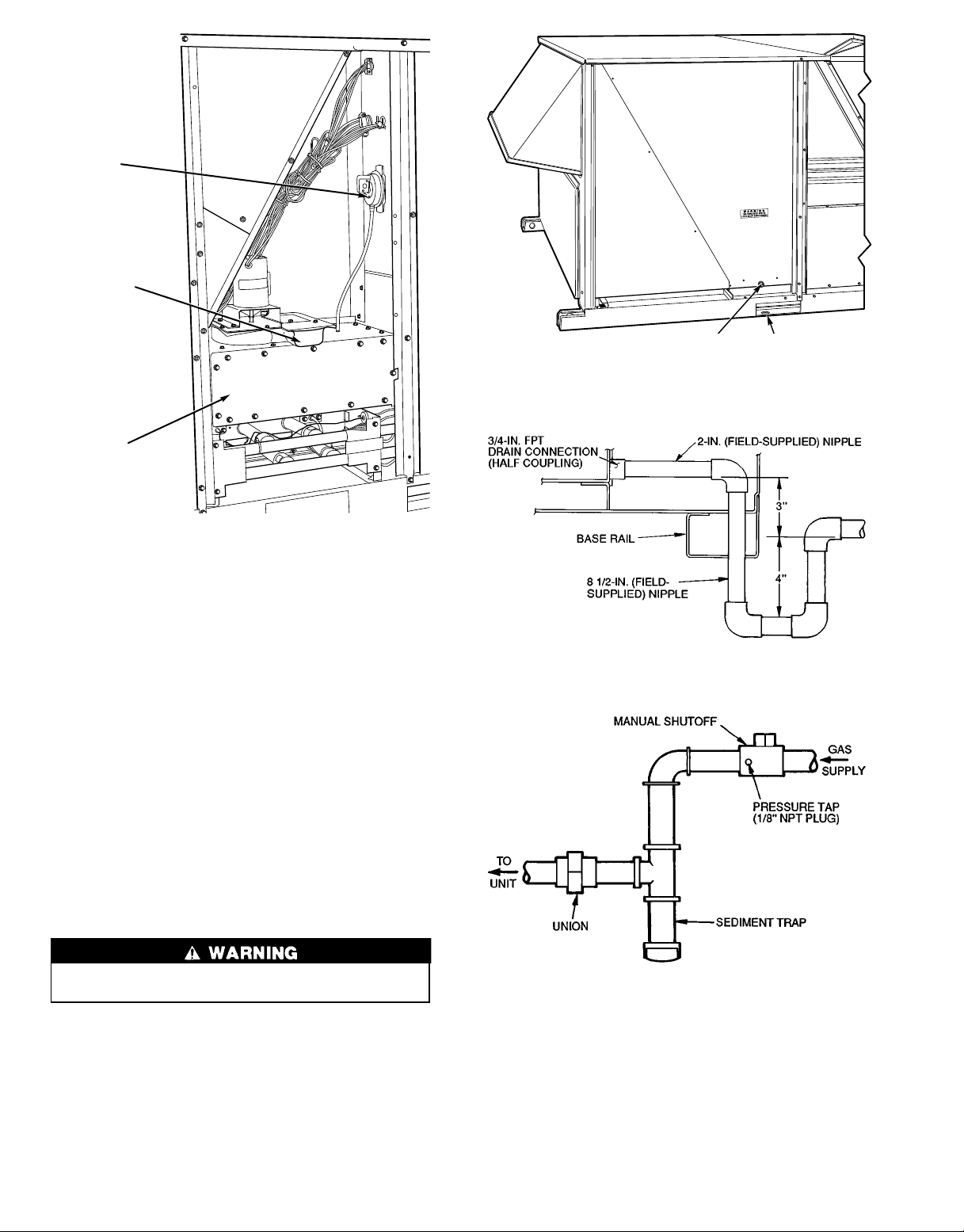
Step6—TrapCondensate Drain — See Fig. 11
for drain location. One3⁄4-in. half coupling is provided
inside unit evaporator section for condensate drain connection. An 81⁄2in. x3⁄4-in. diameter and 2-in. x3⁄4-in. diameter
pipe nipple, coupled to standard3⁄4-in. diameter elbows, provides a straight path down through hole in unit base rail (see
Fig. 12). A trap at least 4-in. deep must be used.
Step 7 — Install Gas Piping — Unit is equipped for
use with natural gas. Installation must conform with local
building codes or, in the absence of local codes, with the
National Fuel Gas Code, ANSI Z223.1.
Install manual gas shutoff valve with a
sure tap for test gage connection at unit. Field gas piping
must include sediment trap and union. See Fig. 13.
1
⁄8-in. NPT pres-
3/4" FPT DRAIN
CONNECTION
1-3/8"
DRAIN HOLE
Fig. 11 — Condensate Drain Details
Fig. 12 — Condensate Drain Piping Details
Do not pressure test gas supply while connected to unit.
Always disconnect union before servicing.
Natural gas pressure at unit gas connection must not be
less than 5 in. wg or greater than 13.5 in. wg.
Size gas-supply piping for 0.5-in. wg maximum pressure
drop. Do not use supply pipe smaller than unit gas connec-
3
tion (
⁄4-in. NPT).
Fig. 13 — Field Gas Piping
8
Page 9
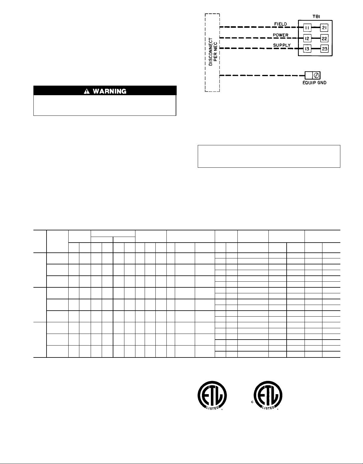
Step 8 — Make Electrical Connections
FIELD POWER SUPPLY — Unit is factory wired for voltage shown on unit nameplate.
When installing units, provide a disconnect per NEC
(National Electrical Code) of adequate size (Table 2).
All field wiring must comply with NEC and local
requirements.
Route power and ground lines through control box end
panel or unit basepan (see Fig. 4 and 5) to connections as
shown on unit wiring diagram and Fig. 14.
The unit must be electrically grounded in accordance
with local codes and NEC ANSI/NFPA 70 (National Fire
Protection Association).
Field wiring must conform to temperature limitations for
type ‘‘T’’wire. All field wiring must comply with NEC and
local requirements.
Transformer no. 1 is wired for 230-v unit. If 208/230-v
unit is to be run with 208-v power supply, the transformer
must be rewired as follows:
1. Remove cap from red (208 v) wire.
2. Remove cap from orange (230 v) spliced wire.
3. Replace orange wire with red wire.
4. Recap both wires.
Table 2 — Electrical Data
NOMINAL
UNIT
VOLTAGE
48HJ
(3 Ph,
60 Hz)
208/230 187 254 39.7 228 — — 3 1.7 3.8 3.7 10.5/10.5 84.5/84.5
015
208/230 187 254 28.2 160 28.2 160 3 1.7 24.8 5 15.8/15.8 105/91
017
208/230 187 254 35.6 198 35.6 198 2 5.5 24.8 10 28.0/28.0 193/168
025
FLA — Full Load Amps
HACR — Heating, Air Conditioning and Refrigeration
IFM — Indoor (Evaporator) Fan Motor
LRA — Locked Rotor Amps
MCA — Minimum Circuit Amps
MOCP — Maximum Overcurrent Protection
NEC — National Electrical Code
OFM — Outdoor (Condenser) Fan Motor
RLA — Rated Load Amps
*This is the maximum size permissible; smaller fuse size may be used where
conditions permit.
VOLTAGE
RANGE
Min Max RLA LRA RLA LRA Qty
460 414 508 19.9 114 — — 3 0.8 1.9 3.7 4.8 42.3
575 518 632 16.0 91 — — 3 0.75 1.5 3 3.9 23.4
460 414 508 14.1 80 14.1 80 3 0.8 10.8 5 7.9 46
575 518 632 11.3 64 11.3 64 3 0.75 8.4 5 6.0 37
460 414 508 17.8 99 17.8 99 2 2.8 10.8 10 14.6 84
575 518 632 14.3 79 14.3 79 2 3.4 8.4 10 13.0 66
LEGEND
COMPRESSOR
No. 1 No. 2
OFM IFM
FLA
LRA
(ea)
Hp FLA LRA FLA LRA FLA MCA MOCP* FLA LRA
(ea)
LEGEND
EQUIP — Equipment
GND — Ground
NEC — National Electrical Code
TB — Terminal Board
NOTE: Maximum wire size for TB1 is 2/0.
Fig. 14 — Field Power Wiring Connections
IMPORTANT: BE CERTAIN UNUSED WIRES
ARE CAPPED. Failure to do so may damage the
transformers.
Operating voltage to compressor must be within voltage
range indicated on unit nameplate. On 3-phase units, voltages between phases must be balanced within 2%.
POWER
EXHAUST
— — 0.57 65/65 100/100 64/64 324/324
4.6 18.8 0.57 70/70 100/100 70/70 343/343
— — 0.30 32 50 32 162
2.3 6.0 0.30 34 50 34 168
— — 0.57 26 40 26 119
2.1 4.8 0.57 28 40 29 124
— — 0.57 84/84 110/100 90/90 499/485
4.6 18.8 0.57 89/89 110/110 95/95 518/504
— — 0.30 42 50 45 238
2.3 6.0 0.30 44 50 47 244
— — 0.57 34 40 36 190
2.1 4.8 0.57 36 45 39 195
— — 0.57 119/119 150/150 127/127 639/614
4.6 18.8 0.57 124/124 150/150 133/133 657/632
— — 0.30 60 70 65 304
2.3 6.0 0.30 63 80 67 310
— — 0.57 52 60 56 241
2.1 4.8 0.57 54 60 59 246
NOTES: In compliance with NEC requirements for multimotor and combination load equipment (refer to NEC Articles 430 and 440), the overcurrent protective device for the unit shall be fuse or HACR breaker. The Canadian units
may be fuse or circuit breaker.
COMBUSTION
FAN MOTOR
POWER SUPPLY
DISCONNECT
SIZE
9
Page 10
Use the following formula to determine the percent volt-
age imbalance.
% Voltage Imbalance:
= 100 x
max voltage deviation from average voltage
average voltage
EXAMPLE: Supply voltage is 460-3-60.
AB =452 v
BC =464 v
AC =455 v
Average Voltage =
452 +464 +455
1371
=
3
3
= 457
Determine maximum deviation from average voltage:
(AB) 457 −452 =5 v
(BC) 464 −457 =7 v
(AC) 457 −455 =2 v
Maximum deviation is 7 v.
Determine percent voltage imbalance:
% Voltage Imbalance =100 x
7
457
=1.53%
This amount of phase imbalance is satisfactory as it is below the maximum allowable 2%.
IMPORTANT: If the supply voltage phase imbalance
is more than 2%, contact your local electric utility company immediately.
Unit failure as a result of operation on improper line
voltage or excessive phase imbalance constitutes abuse and
may cause damage to electrical components.
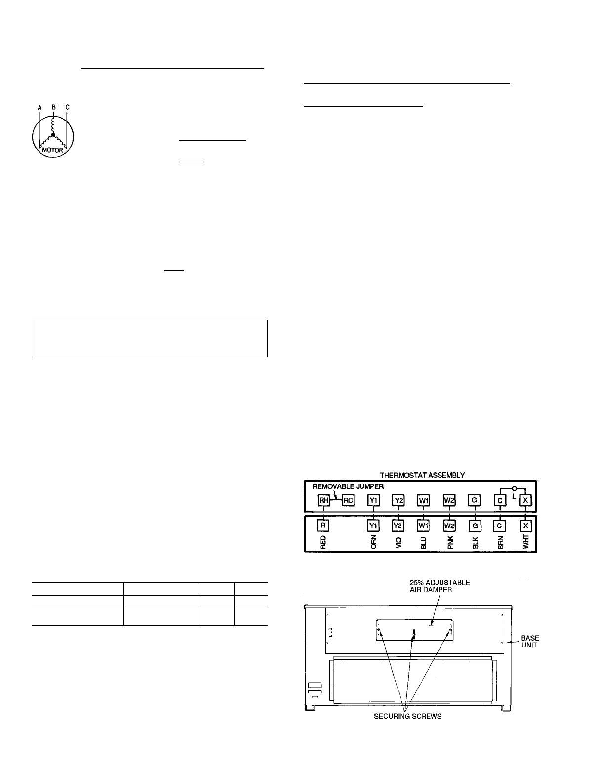
FIELD CONTROL WIRING — Install a Carrier-approved
accessory thermostat assembly according to installation
instructions included with accessory. Locate thermostat assembly on a solid interior wall in the conditioned space to
sense average temperature.
Route thermostat cable or equivalent single leads of colored wire from subbase terminals through conduit in unit to
low-voltage connections as shown on unit label wiring diagram and in Fig. 15.
NOTE: For wire runs up to 50 ft, use no. 18 AWG (American Wire Gage) insulated wire (35 C minimum). For 50 to
75 ft, use no. 16 AWG insulated wire (35 C minimum). For
over 75 ft, use no. 14 AWG insulated wire (35 C minimum).
All wire larger than no. 18 AWG cannot be directly connected at the thermostat and will require a junction box and
splice at the thermostat.
Set heat anticipator settings as follows:
Damper can be preset to admit up to 25% outdoor air into
return-air compartment. To adjust, loosen securing screws
and move damper to desired setting, then retighten screws to
secure damper (Fig. 16).
OPTIONAL FACTORY-INSTALLED ECONOMIZER
Economizer Motor Control Module (See Fig. 17-19) — Set
economizer motor to the D setting (Fig. 18).
Damper Vent Position Setting
1. Set fan switch at ON position (continuous fan operation)
and close night switch if used.
2. Set system selector switch at OFF position.
3. Turn damper adjustment knob located on control module
clockwise slowly until dampers assume desired vent position. Do not manually operate economizer motor. Dam-
age to motor will result.
NOTE: Refer to accessory installation instructions included
with the field-installed economizer for installation information.Also see Accessory Field-Installed Economizer Adjustment section on page 12.
Step10 — Install Outdoor-Air Hood— The outdoor-
air hood is common to 25% air ventilation and economizer.
If economizer is used, all electrical connections have been
made and adjusted at the factory.Assemble and install hood
in the field.
NOTE: The hood top cover, upper and lower filter retainers, hood drain pan, baffle (017 and 025 only), and filter support bracket are secured opposite the condenser end of the
unit. The screens, hood side panels, remaining section of filter support bracket, seal strip, and hardware are in a package
located inside the return-air filter access panel (Fig. 20).
1. Attach seal strip to upper filter retainer. See Fig. 21.
2. Assemble hood top cover, side panels, upper filter re-
tainer, and drain pan (see Fig. 22).
3. Secure lower filter retainer and long portion of support
bracket to unit. See Fig. 22. Leave screws loose on 017
and 025 units.
4. 48HJ017,025 Units Only: Slide baffle behind lower filter
retainer and tighten screws.
Fig. 15 — Field Control Thermostat Wiring
UNIT VOLTAGE UNIT W1 W2
48HJD015 All 1.20 —
48HJD025, HJE015,
HJE017
All 1.20 0.60
Settings may be changed slightly to provide a greater de-
gree of comfort for a particular installation.
Refer to Accessory Remote Control Panel instructions if
required.
Step 9 — Make Outdoor-Air Inlet Adjustments
MANUAL OUTDOOR-AIR DAMPER — All units (except
those equipped with a factory-installed economizer) have a
manual outdoor-air damper to provide ventilation air.
Fig. 16 — 25% Outdoor-Air Section Details
10
Page 11

5. Loosen sheet metal screws for top cover of base unit
located above outdoor-air inlet opening.
6. Match notches in hood top cover with unit top cover screws.
Insert hood flange between top cover flange and unit. Tighten
screws.
7. Insert outdoor-air inlet screens and spacer in channel
created by lower filter retainer and filter support bracket.
8. Attach remaining shorter section of filter support bracket.
Fig.17 — Economizer Damper Assembly — End View
Fig. 19 — Economizer Motor Control
Module Location
Fig. 20 — Outdoor-Air Hood Component Location
LED — Light-Emitting Diode
Fig. 18 — Economizer Motor Control Module
Fig. 21 — Seal Strip Location
11
Page 12

Fig. 22 — Outdoor-Air Hood Details
START-UP
Use the following information and Start-Up Checklist
on page CL-1 to check out unit PRIOR to start-up.
Unit Preparation — Check that unit has been installed
in accordance with these installation instructions and applicable codes.
CompressorMounting — Loosen the compressor hold-
down bolts until sidewise movement of the washer under
each holddown bolt head can be obtained. Do not loosen
completely as bolts are self-locking and will maintain
adjustment.
Internal Wiring — Check all electrical connections in
unit control boxes; tighten as required.
RefrigerantService Ports and Valves— Each 48HJ
unit has 2 Schrader-type service ports per circuit; one on the
suction line and one on the liquid line. Be sure that the caps
on the ports are tight. The units also have 2 service valves
per circuit; one on the suction line and one on the discharge
line. Be sure all valves are open.
Crankcase Heater — Crankcase heater is energized
as long as there is power to the unit.
IMPORTANT: Unit power must be on for 24 hours
prior to start-up. Otherwise, damage to compressor may
result.
Evaporator Fan — Fan belt and pulleys are factory in-
stalled. See Tables 3A, 3B, 4, and 5 for Fan Performance
Data. Remove tape from fan pulley and adjust pulleys on
48HJ015 units as required. See Evaporator-Fan Performance Adjustment section on page 19. Be sure that fans rotate in the proper direction. See Table 6 for air quantity limits. See Table 7 for static pressure drops for accessories and
options. See Fig. 23 and 24 for fan performance using horizontal adapter and power exhaust. To alter fan performance,
see Performance Adjustment sections on page 19.
Condenser-Fansand Motors — Condenser fans and
motors are factory set. Refer to Condenser-Fan Adjustment
section on page 20 as required. Be sure that fans rotate in the
proper direction.
Return-Air Filters — Check that correct filters are in-
stalled in filter tracks (see Table1). Do not operate unit without return-air filters.
Outdoor-AirInlet Screens — Outdoor-air inlet screens
must be in place before operating unit.
Accessory Field-Installed Economizer Adjustment —
air damper is closed and return-air damper is open.
Economizer operation and adjustment are described in
Base Unit Operation section on page 17; and Economizer
Adjustment section on page 20.
Remove filter access panel. Check that outdoor-
NOTES:
1. Dimensions are in millimeters.
2. The 50DP900211high static regain adapter accessory may be used
to provide horizontal supply/return.
Fig. 23 — Horizontal Supply/Return Fan Performance
With 50DP900211 High Static Regain Adapter
NOTE: The 50DP900211 horizontal supply/return adapter accessory
improves 48HJ fan performance by increasing external static pressure by amount shown above.
12
Page 13

Table 3A — Fan Performance Data, 48HJ015, 208/230, 460-V Units
AIRFLOW
(CFM)
3750 741 510 0.58 854 715 0.82 952 921 1.05 1041 1130 1.29 1124 1344 1.53
4000 773 647 0.74 882 859 0.98 978 1071 1.22 1064 1285 1.46 1145 1502 1.71
4250 806 796 0.91 912 1015 1.16 1004 1233 1.40 1089 1452 1.65 1167 1674 1.91
4500 839 958 1.09 942 1183 1.35 1032 1407 1.60 1114 1632 1.86 1191 1859 2.12
4750 873 1134 1.29 972 1365 1.56 1060 1595 1.82 1140 1825 2.08 1215 2056 2.34
5000 908 1323 1.51 1003 1560 1.78 1089 1796 2.05 1167 2032 2.32 1241 2268 2.58
5250 942 1527 1.74 1035 1769 2.02 1118 2011 2.29 1195 2252 2.57 1267 2494 2.84
5500 978 1745 1.99 1067 1992 2.27 1148 2240 2.55 1223 2487 2.83 1293 2733 3.11
5750 1013 1978 2.25 1099 2230 2.54 1179 2484 2.83 1252 2736 3.12 1321 2988 3.40
6000 1049 2227 2.54 1132 2483 2.83 1210 2742 3.12 1282 2999 3.42 1349 3257 3.71
6250 1085 2491 2.84 1166 2751 3.13 1241 3015 3.44 1312 3279 3.74 1378 3541 4.03
AIRFLOW
(CFM)
3750 1203 1562 1.78 1277 1784 2.03 1349 2010 2.29 1417 2240 2.55 1483 2473 2.82
4000 1222 1724 1.96 1294 1950 2.22 1364 2180 2.48 1431 2413 2.75 1495 2650 3.02
4250 1242 1900 2.16 1313 2129 2.43 1381 2362 2.69 1446 2599 2.96 1509 2839 3.23
4500 1264 2089 2.38 1333 2322 2.65 1399 2558 2.91 1463 2799 3.19 1525 3042 3.47
4750 1286 2290 2.61 1354 2528 2.88 1419 2769 3.15 1482 3012 3.43 1542 3259 3.71
5000 1310 2507 2.86 1376 2748 3.13 1440 2992 3.41 1501 3240 3.69 1560 3489 3.98
5250 1335 2737 3.12 1399 2983 3.40 1461 3230 3.68 1522 3481 3.97 ———
5500 1360 2981 3.40 1423 3231 3.68 1484 3483 3.97 1543 3737 4.26 — — —
5750 1386 3241 3.69 1448 3495 3.98 1508 3750 4.27 — — — — — —
6000 1413 3514 4.00 1474 3773 4.30 1532 4032 4.59 — — — — — —
6250 1440 3803 4.33 1500 4066 4.63 1558 4330 4.93 — — — — — —
Bhp — Brake Horsepower Input to Fan
FIOP — Factory-Installed Option
Watts — Input Watts to Motor
NOTES:
1. Boldface indicates standard operating range.
2. indicates field-supplied motor and drive required.
3. All other numbers indicate field-supplied drive required.
4. Factory shipped motor drive range is 1194to 1526 rpm. Other rpms
require a field-supplied drive.
Rpm Watts Bhp Rpm Watts Bhp Rpm Watts Bhp Rpm Watts Bhp Rpm Watts Bhp
Rpm Watts Bhp Rpm Watts Bhp Rpm Watts Bhp Rpm Watts Bhp Rpm Watts Bhp
0.2 0.4 0.6 0.8 1.0
1.2 1.4 1.6 1.8 2.0
LEGEND
EXTERNAL STATIC PRESSURE (in. wg)
EXTERNAL STATIC PRESSURE (in. wg)
5. Static pressure losses (i.e., economizer) must be added to external static pressure before entering Fan Performance table. See
Table 7 for accessory/FIOP static pressure information.
6. Interpolation is permissible. Do not extrapolate.
7. Maximum continuous bhp is 4.25 and the maximum continuous
watts are 3775. Extensive motor and drive testing on these units
ensures that the full horsepower range of the motor can be utilized with confidence. Using your fan motors up to the watts rating
shown will not result in nuisance tripping or premature motor failure. Unit warranty will not be affected.
13
Page 14

Table 3B — Fan Performance Data, 48HJ015, 575-V Units
AIRFLOW
(CFM)
3750 741 510 0.58 854 715 0.82 952 921 1.05 1041 1030 1.29 1124 1344 1.53
4000 773 647 0.74 882 859 0.98 978 1071 1.22 1064 1285 1.46 1145 1502 1.71
4250 806 796 0.91 912 1015 1.16 1004 1233 1.40 1089 1452 1.65 1167 1674 1.91
4500 839 958 1.09 942 1183 1.35 1032 1407 1.60 1114 1632 1.86 1191 1859 2.12
4750 873 1134 1.29 972 1365 1.56 1060 1595 1.82 1140 1825 2.08 1215 2056 2.34
5000 908 1323 1.51 1003 1560 1.78 1089 1796 2.05 1167 2032 2.32 1241 2268 2.58
5250 942 1527 1.74 1035 1769 2.02 1118 2011 2.29 1195 2252 2.57 1267 2494 2.84
5500 978 1745 1.99 1067 1992 2.27 1148 2240 2.55 1223 2487 2.83 1293 2733 3.11
5750 1013 1978 2.25 1099 2230 2.54 1179 2484 2.83 1252 2736 3.12 1321 2988 3.40
6000 1049 2227 2.54 1132 2483 2.83 1210 2742 3.12 1282 2999 3.42 1349 3257 3.71
6250 1085 2491 2.84 1166 2751 3.13 1241 3015 3.44 1312 3279 3.74 1378 3541 4.03
AIRFLOW
(CFM)
3750 1203 1562 1.78 1277 1784 2.03 1349 2010 2.29 1417 2240 2.55 1483 2473 2.82
4000 1222 1724 1.96 1294 1950 2.22 1364 2180 2.48 1431 2413 2.75 1495 2650 3.02
4250 1242 1900 2.16 1313 2129 2.43 1381 2362 2.69 1446 2599 2.96 1509 2839 3.23
4500 1264 2089 2.38 1333 2322 2.65 1399 2558 2.91 1463 2799 3.19 1525 3042 3.47
4750 1286 2290 2.61 1354 2528 2.88 1419 2769 3.15 1482 3012 3.43 1542 3259 3.71
5000 1310 2507 2.86 1376 2748 3.13 1440 2992 3.41 1501 3240 3.69 1560 3489 3.98
5250 1335 2737 3.12 1399 2983 3.40 1461 3230 3.68 1522 3481 3.97 — — —
5500 1360 2981 3.40 1423 3231 3.68 1484 3483 3.97 1543 3737 4.26 — — —
5750 1386 3241 3.69 1448 3495 3.98 1508 3750 4.27 — — — — — —
6000 1413 3514 4.00 1474 3773 4.30 1532 4032 4.59 — — — — — —
6250 1440 3803 4.33 1500 4066 4.63 1558 4330 4.93 — — — — — —
Bhp — Brake Horsepower Input to Fan
FIOP — Factory-Installed Option
Watts — Input Watts to Motor
NOTES:
1. Boldface indicates standard operating range.
2. indicates field-supplied motor and drive required.
3. All other numbers indicate field-supplied drive required.
4. Factory shipped motor drive range is 1201 to 1462 rpm. Other rpms
require a field-supplied drive.
Rpm Watts Bhp Rpm Watts Bhp Rpm Watts Bhp Rpm Watts Bhp Rpm Watts Bhp
Rpm Watts Bhp Rpm Watts Bhp Rpm Watts Bhp Rpm Watts Bhp Rpm Watts Bhp
LEGEND
0.2 0.4 0.6 0.8 1.0
1.2 1.4 1.6 1.8 2.0
EXTERNAL STATIC PRESSURE (in. wg)
EXTERNAL STATIC PRESSURE (in. wg)
5. Static pressure losses (i.e., economizer) must be added to external static pressure before entering Fan Performance table. See
Table 7 for accessory/FIOP static pressure information.
6. Interpolation is permissible. Do not extrapolate.
7. Maximum continuous bhp is 3.45 and the maximum continuous
watts are 3065. Extensive motor and drive testing on these units
ensures that the full horsepower range of the motor can be utilized with confidence. Using your fan motors up to the watts rating
shown will not result in nuisance tripping or premature motor failure. Unit warranty will not be affected.
14
Page 15

Table 4 — Fan Performance Data, 48HJ017 Units
AIRFLOW
(CFM)
4500 630 805 0.9 741 1059 1.2 846 1341 1.5 945 1653 1.9 1039 1993 2.2
4800 659 943 1.1 765 1208 1.4 865 1497 1.7 961 1816 2.0 1052 2163 2.4
5100 688 1094 1.2 789 1371 1.5 885 1668 1.9 977 1993 2.2 1064 2345 2.6
5400 717 1262 1.4 814 1550 1.7 907 1856 2.1 994 2187 2.4 1079 2546 2.8
5700 748 1450 1.6 842 1752 2.0 930 2067 2.3 1015 2406 2.7 1096 2770 3.1
6000 776 1648 1.8 867 1963 2.2 952 2289 2.6 1034 2635 2.9 1112 3004 3.4
6300 804 1861 2.1 892 2190 2.5 975 2526 2.8 1053 2880 3.2 1129 3256 3.6
6600 835 2103 2.4 919 2445 2.7 1000 2793 3.1 1076 3156 3.5 1149 3540 4.0
6900 863 2356 2.6 946 2712 3.0 1024 3072 3.4 1098 3445 3.9 1169 3835 4.3
7200 892 2628 2.9 972 2998 3.4 1049 3371 3.8 1120 3754 4.2 1189 4152 4.6
7500 923 2933 3.3 1001 3318 3.7 1076 3704 4.1 1146 4098 4.6 1213 4506 5.0
AIRFLOW
(CFM)
4500 1128 2355 2.6 1211 2734 3.1 1289 3127 3.5 1363 3531 4.0 1433 3944 4.4
4800 1138 2533 2.8 1219 2921 3.3 1297 3325 3.7 1370 3742 4.2 1440 4170 4.7
5100 1148 2722 3.0 1228 3119 3.5 1305 3532 4.0 1377 3961 4.4 1447 4400 4.9
5400 1160 2928 3.3 1238 3332 3.7 1313 3755 4.2 1385 4192 4.7 1454 4643 5.2
5700 1175 3158 3.5 1251 3569 4.0 1324 3999 4.5 1395 4445 5.0 1462 4906 5.5
6000 1188 3398 3.8 1262 3814 4.3 1334 4250 4.8 1403 4704 5.3 1470 5173 5.8
6300 1203 3654 4.1 1275 4075 4.6 1344 4517 5.1 1412 4976 5.6 1478 5453 6.1
6400 1221 3944 4.4 1290 4370 4.9 1358 4817 5.4 1424 5283 5.6 1489 5765 6.5
6900 1238 4245 4.8 1305 4676 5.2 1371 5128 5.7 1436 5598 6.3 1499 6087 6.8
7200 1256 4569 5.1 1322 5006 5.6 1386 5463 6.1 1449 5938 6.6 1509 6420 7.2
7500 1278 4930 5.5 1341 5373 6.0 1403 5835 6.5 1465 6316 7.1 1515 6733 7.5
Bhp — Brake Horsepower Input to Fan
FIOP — Factory-Installed Option
Watts — Input Watts to Motor
NOTES:
1. Boldface indicates standard operating range.
2. indicates field-supplied motor and drive required.
3. All other numbers indicate field-supplied drive required.
4. Factory shipped motor drive range is 1238 to 1494 rpm. Other rpms
require a field-supplied drive.
Rpm Watts Bhp Rpm Watts Bhp Rpm Watts Bhp Rpm Watts Bhp Rpm Watts Bhp
Rpm Watts Bhp Rpm Watts Bhp Rpm Watts Bhp Rpm Watts Bhp Rpm Watts Bhp
LEGEND
0.2 0.4 0.6 0.8 1.0
1.2 1.4 1.6 1.8 2.0
EXTERNAL STATIC PRESSURE (in. wg)
EXTERNAL STATIC PRESSURE (in. wg)
5. Static pressure losses (i.e., economizer) must be added to external static pressure before entering Fan Performance table. See
Table 7 for accessory/FIOP static pressure information.
6. Interpolation is permissible. Do not extrapolate.
7. Maximum continuous bhp is 5.9 and themaximumcontinuouswatts
are 5180. Extensive motor and drive testing on these units ensures that the full horsepower range of the motor can be utilized
withconfidence.Usingyourfanmotorsup to the watts rating shown
will not result in nuisance tripping or premature motor failure. Unit
warranty will not be affected.
15
Page 16

Table 5 — Fan Performance Data, 48HJ025 Units
AIRFLOW
(CFM)
6000 800 1732 1.88 891 2047 2.22 975 2376 2.58 1055 2728 2.96 1133 3104 3.37
6500 853 2134 2.32 939 2471 2.68 1018 2819 3.06 1094 3185 3.46 1167 3573 3.88
7000 907 2596 2.82 989 2957 3.21 1064 3324 3.61 1136 3707 4.02 1205 4107 4.46
7500 962 3123 3.39 1039 3507 3.81 1111 3895 4.23 1179 4295 4.66 1245 4710 5.11
8000 1017 3717 4.04 1091 4126 4.48 1160 4536 4.93 1225 4954 5.38 1287 5386 5.85
8500 1072 4385 4.76 1143 4818 5.23 1209 5250 5.70 1271 5688 6.18 1332 6137 6.66
9000 1128 5129 5.57 1196 5587 6.07 1260 6042 6.56 1323 6501 7.06 1377 6968 7.57
9500 1185 5955 6.47 1250 6437 6.99 1311 6915 7.51 1369 7395 8.03 1424 7881 8.56
10000 1241 6865 7.45 1304 7372 8.00 1363 7873 8.65 1419 8376 9.09 1472 8882 9.64
AIRFLOW
(CFM)
6000 1208 3504 3.80 1282 3926 4.26 1353 4368 4.74 1421 4826 5.24 1488 5299 5.75
6500 1239 3983 4.32 1308 4415 4.79 1376 4866 5.28 1442 5337 5.79 1507 5823 6.32
7000 1273 4529 4.92 1339 4970 5.40 1403 5432 5.90 1467 5911 6.42 1520 6339 6.88
7500 1309 5143 5.58 1372 5597 6.08 1434 6067 6.59 1494 6558 7.12 1548 7014 7.62
8000 1349 5833 6.33 1409 6297 6.84 1467 6779 7.36 1529 7313 7.94 ———
8500 1390 6600 7.17 1447 7077 7.68 1504 7571 8.22 ——————
9000 1433 7446 8.08 1488 7938 8.62 —————————
9500 1478 8378 9.10 ————————————
10000 1524 9396 10.20 ————————————
Bhp — Brake Horsepower Input to Fan
FIOP — Factory-Installed Option
Watts — Input Watts to Motor
NOTES:
1. Boldface indicates standard operating range.
2. All other numbers indicates field-supplied drive required.
3. Factory shipped motor drive range is 1323 to 1579 rpm. Other rpms
require a field-supplied drive.
4. Static pressure losses (i.e., economizer) must be added to external static pressure before entering Fan Performance table. See
Table 7 for accessory/FIOP static pressure information.
Rpm Watts Bhp Rpm Watts Bhp Rpm Watts Bhp Rpm Watts Bhp Rpm Watts Bhp
Rpm Watts Bhp Rpm Watts Bhp Rpm Watts Bhp Rpm Watts Bhp Rpm Watts Bhp
LEGEND
0.2 0.4 0.6 0.8 1.0
1.2 1.4 1.6 1.8 2.0
EXTERNAL STATIC PRESSURE (in. wg)
EXTERNAL STATIC PRESSURE (in. wg)
5. Interpolation is permissible. Do not extrapolate.
6. Maximum continuous bhp is 10.2 for 208/230 and 575-v units and
11.8for 460-v units. The maximum continuous watts are 9510 for
the 208/230 and 575-v units and 11,000 for the 460-v units. Extensive motor and drive testing on these units ensures that the full
horsepower range of the motor can be utilized with confidence.
Using your fan motors up to the watts rating shown will not result
in nuisance tripping or premature motor failure. Unit warranty will
not be affected.
Table 6 — Air Quantity Limits
UNIT 48HJ MINIMUM CFM MAXIMUM CFM
015 3,750 6,250
017 4,500 7,500
025 6,000 10,000
Fig. 24 — Fan Performance Using Accessory
Power Exhaust
16
Page 17

Table 7 — Accessory/FIOP Economizer Static Pressure (in. wg)
UNIT
480HJ
015, 017 All
025 All
LEGEND
BHP — Brake Horsepower
FIOP — Factory-Installed Option
NOTES:
1. The factory-assembled horizontal adapter substantially improves
fan performance. See Fig. 24.
UNIT
VOLTAGE
Gas Heat — Verify gas pressures before turning on heat
as follows:
1. Turn off manual gas stop.
2. Connect pressure gage to supply gas tap (See Fig. 13 on
page 8).
3. Connect pressure gage to manifold pressure tap on gas
valve.
4. Turn on manual gas stop and set thermostat to HEAT po-
sition. After the unit has run for several minutes, verify
that incoming pressure is 5.0 in. wg or greater, and that
the manifold pressure is 3.5 in. wg. If manifold pressure
must be adjusted, refer to Gas Valve Adjustment section
on page 22.
5. After unit has been in operation for 5 minutes, check tem-
perature rise across the heat exchangers. See unit informative plate for correct rise limits of the heat supplied.
Air quantities may need to be adjusted to bring the actual
rise to within the allowable limits.
Base Unit Operation
COOLING, UNITS WITHOUT ECONOMIZER — When
thermostat calls for cooling, terminals G and Y1 are energized. The indoor (evaporator) fan contactor (IFC) and
compressor contactor no. 1 (C1) are energized and evaporatorfan motor (IFM), compressor no. 1 (017,025) or unloaded
compressor (015), and condenser fan start. The condenserfan motors run continuously while unit is cooling. If the thermostat calls for a second stage of cooling by energizing Y2,
compressor contactor no. 2 (C2) is energized and compressor no. 2 starts (017,025), or compressor no. 1 runs fully
loaded (015).
A freeze protection thermostat (FPT) is located on the
evaporator coil. It detects frost build-up and locks out the
compressors, allowing the coil to clear. Once frost has melted,
the compressors can be reenergized by resetting the
thermostat.
HEATING, UNITS WITHOUT ECONOMIZER
NOTE: The 48HJD015 units have 1 stage of heat, and the
48HJE015, 48HJE017, and HJD025 units have 2 stages of
heat.
First Stage — Turn unit power on. Open manual gas line
valve. Set thermostat system switch at HEAT or AUTO. position and set fan switch to AUTO. position for heating.
First-stage thermostat calls for heat. Time-delay relay for
evaporator fan begins timer sequence. Induced-draft relay
closes, and induced-draft motor starts.
CFM
3,750 .03
4,000 .03
5,000 .05
6,000 .07
7,500 .10
6,000 .07
7,200 .09
9,000 .11
10,000 .12
2. The static pressure must be added to external static pressure. The
sum and the evaporator entering-air cfm should then be used in
conjunction with the Fan Performance table to determine blower
rpm, bhp, and watts.
ECONOMIZER
PRESSURE DROP
Pressure switch closes and pilot valve no. 1 opens, allowing gas to flow to the first-stage pilot. Spark ignitor
ignites pilot flame. Sensor detects flame and the main gas
valve no. 1 opens. Gas flows to main burners and first-stage
burners ignite. Spark igniter turns off.
When sequence is complete, time-delay relay closes and
evaporator fans start.
Second-Stage — On 2-stage units, with an additional heating call, the second-stage thermostat closes. (The control relay [HR2] closes during the first stage of operation.) Pilot
valve no. 2 opens, and the spark ignitor ignites pilot. The
sensor detects a flame and energizes main gas valve coil
no. 2, opening main gas valve no. 2. Gas flows to the main
burners, and the second-stage burners ignite. The spark ignitor
turns off.
When the second-stage thermostat is satisfied, the secondstage gas valve closes.
When the first-stage thermostat is satisfied, the first-stage
gas valve closes. The induced-draft motor turns off, the time
delay relay is deenergized, and the timer sequence begins.
When the sequence is complete, the evaporator-fan motor
turns off.
COOLING, UNITS WITH ECONOMIZER — Upon a call
for cooling, when outdoor ambient is above the changeover
control setting, the economizer damper moves to VENT
position. The compressors and evaporator and condenser fans
energize and operate as per Cooling, Units Without Economizer section above.
Upon a first call for cooling, when outdoor ambient is below the changeover control setting, the evaporator fan starts
and the economizer is fully open. The compressors remain
off.
Upon a second-stage call for cooling, compressor no. 1
(017,025) or unloaded compressor (015) is energized and mechanical cooling is integrated with economizer cooling. If
the outdoor-air temperature drops below 50 F,a cooling lockout switch prevents the compressors from running.
When supply-air temperature drops below a fixed set point,
the economizer damper modulates to maintain the temperature at the fixed set point.
HEATING, UNITS WITH ECONOMIZER — Outdoor-air
damper stays at VENT position while evaporator fan is
operating.
17
Page 18

SERVICE
Before performing service or maintenance operations on
unit, turn offmain power switch to unit. Electrical shock
could cause personal injury.
Cleaning— Inspect unit interior at beginning of each heat-
ing and cooling season and as operating conditions require.
Remove unit top panel and/or side panels for access to unit
interior.
MAINAND PILOT BURNERS — At the beginning of each
heating season, inspect for deterioration or blockage due to
corrosion or other causes. Observe the pilot and main burner
flames through view port (in condenser section), and adjust
if necessary. Refer to Pilot Adjustment or Main Burners sections on pages 22 and 23.
FLUE GAS PASSAGEWAYS— The flue collector box and
heat exchanger cells may be inspected by removing heat exchanger access panel (Fig. 4 and 5), flue box cover,and main
burner assembly (Fig. 25). Refer to Main Burners section on
page 23 for burner removal sequence. If cleaning is required, remove heat exchanger turbulators (Fig. 26) and clean
all parts with a wire brush.
COMBUSTION-AIR BLOWER — Clean periodically to assure proper airflow and heating efficiency. Inspect blower
wheel every fall and periodically during heating season. For
the first heating season, inspect blower wheel bi-monthly to
determine proper cleaning frequency.
To inspect blower wheel, remove heat exchanger access
panel. Shine a flashlight into opening to inspect wheel. If
cleaning is required, remove motor and wheel assembly by
removing screws holding motor mounting plate to top of combustion fan housing (Fig. 25 and 26). The motor and wheel
assembly will slide up and out of the fan housing. Remove
the blower wheel from the motor shaft and clean with a detergent or solvent. Replace motor and wheel assembly.
Fig. 25 — Typical Gas Heating Section
(48HJE015, 48HJE017, and 48HJD025 Shown)
EVAPORATOR COIL — Clean as required with commercial coil cleaner.
CONDENSER COIL — Clean condenser coil annually and
as required by location and outdoor-air conditions. Inspect
coil monthly; clean as required.
CONDENSATE DRAIN — Check and clean each year at
start of cooling season. In winter, keep drains and traps dry.
FILTERS — Clean or replace at start of each heating and
cooling season, or more often if operating conditions require. Refer to Table 1 for type and size.
OUTDOOR-AIR INLET SCREENS — Clean screens with
steam or hot water and a mild detergent. Do not use disposable filters in place of screens.
Lubrication
COMPRESSORS — Each compressor is charged with the
correct amount of oil at the factory. Observe the level in the
sight glass immediately after shutdown while the oil is still
warm. If the oil level is observed when the oil is cold, the
level observed may be a mixture of oil and refrigerant which
is not a true indication of the oil level. If oil level observed
is not between the low limit and high limit levels as indicated in Fig. 27, add oil until it is in the correct range.
Fig. 26 — Typical Heating Section With
Main Burners Removed
(48HJE015, 48HJE017, and 48HJD025 Shown)
Fig. 27 — Compressor Sight Glass Oil Level
18
Page 19

FAN SHAFT BEARINGS — For 015 units, the bearings are
permanently lubricated. No field lubrication is required. For
017 and 025 units, the bearings are of the pillow block type
and have grease fittings. The bearing opposite the motor end
has an extended tube line so it can be lubricated from the
motor side. Lubricate the bearings twice annually.
Typical lubricants are given below:
MANUFACTURER LUBRICANT
Texaco Regal AFB-2*
Mobil Mobilplex EP No. 1
Sunoco Prestige 42
Texaco Multifak 2
*Preferred lubricant because it contains rust and oxidation inhibitors.
CONDENSER- AND EVAPORATOR-FAN MOTOR
BEARINGS — The condenser- and evaporator-fan motors
have permanently-sealed bearings, so no field lubrication is
necessary.
Evaporator Fan, 48HJ015 Units
PERFORMANCEADJUSTMENT— The 48HJ015 fan motor pulleys are factory set for speed shown in Table 1.
To change fan speeds:
1. Shut off unit power supply.
2. Loosen belt by loosening fan motor mounting plate nuts.
3. Loosen movable-pulley flange setscrew (see Fig. 28).
4. Screw movable flange toward fixed flange to increase speed
and away from fixed flange to decrease speed. Increasing
fan speed increases load on motor. Do not exceed maximum speed specified in Table 1.
5. Set movable flange at nearest keyway of pulley hub and
tighten setscrew.
To align fan and motor pulleys:
1. Loosen fan pulley setscrews.
2. Slide fan pulley along fan shaft.
3. Make angular alignment by loosening motor from mounting plate.
SERVICE AND REPLACEMENT (See Fig. 29)
NOTE: To remove belts only, follow Steps 1-7.
1. Remove filter and supply-air section panels.
2. Remove unit top cover.
3. Remove coil guard.
4. Loosen screws A and B on both sides of motor mount
assembly.
5. Loosen screw C.
6. Rotate motor mount assembly (with motor attached) as
far as possible away from evaporator coil.
7. Remove belt.
8. Rotate motor mount assembly back past original position toward evaporator coil.
9. Remove motor mounting nuts D and E (both sides).
10. Lift motor up through top of unit.
11. Reverse above procedure to reinstall motor.
12. Check and adjust belt tension as necessary.
2. Loosen nuts on the 2 carriage bolts in the mounting base.
Install jacking bolt and plate under motor base (bolt and
plate are shipped in installer’s packet). Using bolt and
plate, raise motor to top of slide and remove belt. Secure
motor in this position by tightening the nuts on the carriage bolts.
3. Loosen movable-pulley flange setscrew (see Fig. 28).
Fig. 28 — Evaporator-Fan Alignment and
Adjustment
Evaporator Fan, 48HJ017,025 Units
PERFORMANCEADJUSTMENT— Fan motor pulleys are
factory set for speed shown in Table 1.
To change fan speeds:
1. Shut off unit power supply.
Fig. 29 — 48HJ015 Evaporator-Fan
Motor Adjustment
19
Page 20

SERVICE AND REPLACEMENT (See Fig. 30) — The
48HJ017,025 units use a fan motor mounting system that
features a slide-out motor mounting plate. Toreplace or service the motor, slide out the bracket.
1. Remove the evaporator-fan access panel and the heating control access panel.
2. Remove the center post (located between the evaporator
fan and heating control access panels) and all screws
securing it.
3. Loosen nuts on the two carriage bolts in the motor mounting base.
4. Using jacking bolt under motor base, raise motor to top
of slide and remove belt. Secure motor in this position
by tightening the nuts on the carriage bolts.
5. Remove the belt drive.
6. Remove jacking bolt and tapped jacking bolt plate.
7. Remove the 2 screws that secure the motor mounting
plate to the motor support channel.
8. Remove the 3 screws from the end of the motor support
channel that interfere with the motor slide path.
9. Slide out the motor and motor mounting plate.
10. Disconnect wiring connections and remove the 4 mounting bolts.
11. Remove the motor.
12. To install the new motor, reverse Steps 1-11.
2. Turn the thermostat fan switch to the ON position. The
damper will go to the vent position.
3. Adjust the vent position with the minimum position adjustment on the economizer motor control module. See
Fig. 18.
4. Set the system selector switch to COOL position and set
the cooling temperature selector to its lowest setting.
NOTE: The Cooling mode may also be simulated by
removing the thermostat wires from terminals Y1 and
Y2 and installing a jumper between terminals R and Y1.
Refer to unit label diagram for terminal locations.
Belt Tension Adjustment — To adjust belt tension:
1. Loosen fan motor bolts.
2. a. 015 Units: Move motor mounting plate up or down
for proper belt tension (
1
⁄2in. deflection with one
finger).
b. 017,025 Units: Turn motor jacking bolt to move mo-
tor mounting plate up or down for proper belt tension
3
⁄8in. deflection at midspan with one finger [9 lb force]).
(
3. Tighten nuts.
4. Adjust bolts and nut on mounting plate to secure motor
in fixed position.
Condenser-Fan Adjustment
48HJ015,017 UNITS (Fig. 31)
1. Shut off unit power supply.
2. Remove access panel(s) closest to the fan to be
adjusted.
3. Loosen fan hub setscrews.
4. Adjust the fan height on the shaft using a straightedge
placed across the fan orifice.
5. Tighten setscrews and replace panel(s).
6. Turn on unit power.
48HJ025 UNITS (Fig. 32)
1. Shut off unit power supply.
2. Remove fan top-grille assembly and loosen fan hub screws.
3. Adjust fan height on unit, using a straightedge placed across
the fan orifice.
4. Tighten setscrews and replace rubber hubcap to prevent
hub from rusting to motor shaft.
5. Fill hub recess with permagum if rubber hubcap is
missing.
NOTE:A31⁄2-in. bolt and threaded plate are included in the installer’s
packet. They can be added to the motor support channel below the
motor mounting plate to aid in raising the motor.
Fig. 30 — 48HJ017,025 Evaporator-Fan
Motor Section
Fig. 31 — Condenser Fan Adjustment,
48HJ015,017
Economizer Adjustment — Refer to Tables 8 and 9
for economizer checkout procedures. Make certain the outdoorair damper is fully closed and the return-air damper is fully
open before completing the following steps:
1. Turn on power to the unit.
Fig. 32 — Condenser-Fan Adjustment,
48HJ025
20
Page 21

5. Set the outdoor-air thermostat (OAT),located in the economizer section of the unit to 75 F.
6. If the outdoor temperature is below 75 F, the economizer will control the mixed air with the mixed-air sensor.Ifthe outdoor air is above 75 F ,place a jumper around
the contacts of the OAT.
7. Jumper terminal T to terminal T1 on the module (see
Fig. 18). The economizer will go to the full open position.
The outdoor-air damper will go to the full open position, and the return-air damper will go to the full closed
position.
8. Adjust mechanical linkage, if necessary, for correct positioning. If may be necessary to remove the filters to
adjust the linkage.
9. Remove the jumper from around the contacts of the OAT
if installed in Step 6. Remove the jumper from terminals T and T1 installed in Step 7.
10. If the Cooling mode was simulated to operate the unit
in Step 4, remove the jumper and reconnect the thermostat wires to terminals Y1 and Y2.
Table 8 — Economizer Checkout Procedures
TEST PROCEDURE RESULTS
A. Disconnect power at TR and
TR1. Disconnect jumper be-
tween P and P1. See Fig. 18.
B. Jumper TR to 1.
C. Jumper T1 to T.
D. Disconnect outdoor-air ther-
mostat connections from S
and +. Factory-installed
800 ohm resistor should re-
main connected to S
E. Reconnect power to terminals
TR and TR1.
TEST PROCEDURE RESULTS
Disconnect factory-installed resistor from terminals S
and +.
R
R
and +.
O
1. LED (light-emitting diode)
should be off.
2. Motor is in closed position.
1. LED (light-emitting diode)
should be on.
2. Motor drives toward open.
Unit panels must be in place when unit is operating dur-
ing charging procedure.
NO CHARGE — Use standard evacuating techniques. After
evacuating system, weigh in the specified amount of
refrigerant (refer to Table 1).
LOW CHARGE COOLING — Using appropriate cooling
charging chart (see Fig. 33-35), add refrigerant until conditions of the chart are met. Note that charging charts are different from those normally used. Charts are based on charging units to correct superheat for various operating conditions.
An accurate pressure gage and temperature sensing device
are required. Connect temperature sensing device to service
port on suction line and insulate it so that outdoor ambient
temperature does not affect reading. Indoor-air cfm must be
within normal operating range of unit.
TO USE COOLING CHARGING CHART — Take outdoor
ambient temperature and read the suction pressure gage. Refer to appropriate chart to determine correct suction temperature. If suction temperature is high, add refrigerant. If
suction temperature is low, carefully reclaim some of the charge.
Recheck suction pressure as charge is adjusted.
Pilot Light — If pilots do not light as described in Gas
Heat section on page 17, be sure that pilot orifice is not obstructed, then check for spark ignitor malfunctions as follows:
1. Shut off control supply power to ignitor control pack (ICP).
1
2. Check that spark gap is
3. Check that ICP is securely grounded.
4. Check that high-voltage lead is securely connected between ICP and electrode body.
5. Restore power to ICP. Check that 24 v is supplied
to terminal TH of ICP.
6. Check unit label diagram for correct terminal usage if any
wires are removed.
⁄8in. 61⁄32inch.
Table 9 — High and Low Outdoor-Air Temperature
TEST PROCEDURE RESULTS
A. Reconnect factory-installed
800 ohm resistor between terminals S
B. Connect 1200 ohm checkout
resistor between terminals S
and +.
C. Turn set point potentiometer
to position A.
D. Turn set point potentiometer
to position D.
E. Disconnect 1200 ohm check-
out resistor.
and +.
R
O
Low outdoor-air temperature
test results:
1. LED (light-emitting diode)
should be on.
2. Motor drives toward open.
High outdoor-air temperature
test results:
1. LED should be off.
2. Motor drives toward closed.
PowerFailure — Dampers have a spring return. In event
of power failure, dampers will return to fully closed position
until power is restored. Do not manually operate damper
motor.
Refrigerant Charge — Amount of refrigerant charge
is listed on unit nameplate and in Table 1. Refer to Carrier
GTAC II; Module 5; Charging, Recovery, Recycling, and Reclamation section for charging methods and procedures.
Fig. 33 — Cooling Charging Chart, 48HJ015
21
Page 22

Fig. 34 — Cooling Charging Chart, 48HJ017
7. Check for proper burner operation by cycling the burners. Wait 30 seconds between burner cycles.
8. Check that all unit panels are in place before leaving unit.
Gas Valve Adjustment
NATURAL GAS — The gas valve opens and closes in response to the thermostat or limit control.
When power is supplied to valve terminals 3 and 4, the
pilot valve opens to the preset position. When power is supplied to terminals 1 and 2, the main valve opens to its preset
position.
The regular factory setting is stamped on the valve body
(3.5 in. wg).
To adjust regulator:
1. Set thermostat at setting for no call for heat.
2. Turn main gas valve to OFF position.
1
3. Remove
sure tap connection. Install a suitable pressure-measuring
device.
4. Set main gas valve to ON position.
5. Set thermostat at setting to call for heat.
6. Remove screw cap covering regulator adjustment screw
(See Fig. 36).
7. Turn adjustment screw clockwise to increase pressure or
counterclockwise to decrease pressure.
8. Once desired pressure is established, set thermostat set-
ting for no call for heat, turn off main gas valve, remove
pressure-measuring device and replace
and screw cap.
⁄8-in. pipe plug from manifold or gas valve pres-
1
⁄8-in. pipe plug
Fig. 35 — Cooling Charging Chart, 48HJ025
Pilot Adjustment
1. Set system selector switch at OFF position to shut off unit.
Turn off power to unit.
2. Remove screw cap cover on pilot gas valve to expose
adjusting screw (See Fig. 36).
3. Turn valve knobs to pilot position.
4. Turnon power to unit. Set system selector switch to HEAT
position and set thermostat to a setting that will call for
heat. Pilot ignites.
5. Witha small screwdriver, turn adjustment screw until flame
fully engulfs sensor. Flame can be observed through view
port (Fig. 37).
6. Turn off power to unit. Replace cap on pilot gas valve.
Return valve knob(s) to original position.
22
Fig. 36 — Gas Valve
VIEW
PORT
PRIMARY AIR
SHUTTER
MAIN BURNER
SECTION
Fig. 37 — Typical Heating Section
FLUE BOX
COVER
Page 23

Main Burners — For most applications, main burners
are factory set and should require no adjustment. However,
if burner adjustment is necessary:
1. Perform pilot adjustment.
2. Turn gas valve to ON position. Allow unit to operate at
least 15 minutes with burner access panel in place.
3. Remove access panel.
4. Loosen primary air shutter (Fig. 37) and adjust to a minimum opening of
5. Retighten primary air shutter and reinstall access panel.
To check ignition of main burners and fan switch operation, move thermostat dial above and below room temperature several times, pausing at least one minute between cycles.
MAIN BURNER REMOVAL
1. Shut off (field-supplied) manual main gas valve.
2. Shut off power to unit.
3. Remove unit control box/gas valve access panel, burner
section access panel, and center post (Fig. 4 and 5).
4. Disconnect pilot ignitor and pilot proving sensor leads at
ICP, rollout switch leads at switch, and pilot tube gas connection(s) at the pilot orifice.
5. Disconnect gas connection(s) from between gas valve(s)
and main burners.
6. Remove 2 screws securing burner assembly to base unit.
7. Slide burner assembly out of unit.
5
⁄8inch.
Filter Drier — Replace whenever refrigerant system is
exposed to atmosphere.
Protective Devices
COMPRESSOR PROTECTION
Overcurrent — Each compressor has one manual reset, cali-
brated trip, magnetic circuit breaker. Do not bypass connections or increase the size of the circuit breaker to correct trouble.
Determine the cause and correct it before resetting the breaker.
Overtemperature — Each compressor has an internal protector to protect it against excessively high discharge gas
temperatures.
Crankcase Heater— Each compressor has a 125-watt crankcase heater to prevent absorption of liquid refrigerant by oil
in the crankcase when the compressor is idle. Since power
for the crankcase heaters is drawn from the unit incoming
power, main unit power must be on for the heaters to be
energized.
IMPORTANT: After a prolonged shutdown or service job, energize the crankcase heaters for 24 hours
before starting the compressors.
Compressor Lockout — If any of the safeties (high-, lowpressure, freeze protection thermostat, compressor internal
thermostat) trip, or if there is loss of power to the compressors, the cooling lockout (CLO) will lock the compressors
off. To reset, manually move the thermostat setting.
EVAPORATOR-FAN MOTOR PROTECTION —Amanual
reset, calibrated trip, magnetic circuit breaker protects against
overcurrent. Do not bypass connections or increase the size
of the breaker to correct trouble. Determine the cause and
correct it before resetting the breaker.
CONDENSER-FAN MOTOR PROTECTION — Each
condenser-fan motor is internally protected against
overtemperature.
HIGH- AND LOW-PRESSURE SWITCHES — If either
switch trips, or if the compressor overtemperature switch activates, that refrigerant circuit will be automatically locked
out by the CLO. To reset, manually move the thermostat
setting.
FREEZE PROTECTION THERMOSTAT (FPT) — An
FPT is located on the evaporator coil. It detects frost
build-up and turns off the compressor, allowing the coil to
clear. Once the frost has melted, the compressor can be
reenergized by resetting the CLO from the thermostat.
Relief Devices — All units have relief devices to pro-
tect against damage from excessive pressures (i.e., fire). These
devices protect the high and low side.
Control Circuit, 24-V — This control circuit is pro-
tected against overcurrent by a 3.2-amp circuit breaker. Breaker
can be reset. If it trips, determine cause of trouble before
resetting.
Replacement Parts — A complete list of replacement
parts may be obtained from any Carrier distributor upon
request.
23
Page 24

Fig. 38 — Typical Wiring Schematic (48HJ025 Shown)
24
Page 25

Fig. 38 — Typical Wiring Schematic (48HJ025 Shown) (cont)
25
Page 26

Fig. 39 — Typical Component Arrangement (48HJ025 Shown)
26
Page 27

LEGEND FOR FIG. 38 and 39
AHA — Adjustable Heat Anticipator
BKR W/AT — Breaks with Amp Turns
C—Contactor, Compressor
CB — Circuit Breaker
CC — Cooling Compensator
CH — Crankcase Heater
CLO — Compressor Lockout
CLS — Compressor Lockout Switch
COMP — Compressor Motor
CR — Control Relay
CT — Current Transformer
DM — Damper Motor
DU — Dummy Terminal
EQUIP — Equipment
FPT — Freeze Protection
FU — Fuse
GND — Ground
HPS — High-Pressure Switch
HR — Heat Relay
HV — High Voltage
I—Ignitor
ICP — Ignitor Control Pack
IDM — Induced-Draft Motor
IDR — Induced-Draft Relay
IFC — Indoor (Evaporator)
IFCB — Indoor (Evaporator)
Thermostat
Fan Contactor
Fan Circuit Breaker
IFM — Indoor (Evaporator)
IFR — Indoor (Evaporator)
IP — Internal Protector
L—Light
LOR — Lockout Relay
LPS — Low-Pressure Switch
LS — Limit Switch
MAT — Mixed-Air Thermostat
MGV — Main Gas Valve
NEC — National Electrical Code
OAT — Outdoor-Air Thermostat
OFC — Outdoor (Condenser)
OFM — Outdoor (Condenser)
PGV — Pilot Gas Valve
PL — Plug Assembly
PRI — Primary
PS — Pressure Switch
QT — Quadruple Terminal
R—Relay
RS — Rollout Switch
SN — Sensor
SW — Switch
TB — Terminal Block
TC — Thermostat Cooling
TDR — Time Delay Relay
Fan Motor
Fan Relay
Fan Contactor
Fan Motor
TH — Thermostat Heating
TRAN — Transformer
Terminal (Marked)
Terminal (Unmarked)
Terminal Block
Splice
Splice (Marked)
Splice (Field Supplied)
Factory Wiring
Field Control Wiring
Field Power Wiring
Accessory or Optional Wiring
To Indicate Common Potential Only,
Not To Represent Wiring
NOTES:
1. Compressor and fan motors thermally protected; 3-phase motors
protected against primary single-phasing conditions.
2. If any of the original wire furnished must be replaced, it must be
replaced with type 90 C wire or its equivalent.
3. Jumpers are omitted when unit is equipped with economizer.
4. Set thermostat heat anticipator(s):
UNIT W1 W2 VOLTAGE
48HJD015 1.20 — All
48HJD025, HJE015,
HJE017
1.20 0.60 All
5. CB must-trip amps are equal to or less than 140% full load amps.
6. Number(s) indicates the line location of used contacts. A bracket
over (2) numbers signifies a single-pole, double-throw contact. An
underlined number signifies a normally-closed contact. Aplain(no
line) number signifies a normally-open contact.
7. The CLO locks out the compressor to prevent short cycling on compressoroverload and safety devices. Before replacing CLO, check
these devices.
27
Page 28

Page 29

Page 30

PACKAGED SERVICE TRAINING
Our packaged service training programs provide an excellent way to increase your knowledge of the
equipment discussed in this manual. Product programs cover:
• Unit Familiarization
• Installation Overview
A large selection of product, theory, and skills programs is available. All programs include a video
cassette and/or slides and a companion booklet. Use these for self teaching or to conduct full training
sessions.
For a free Service Training Material Catalog (STM), call 1-800-962-9212. Ordering instructions are
included.
• Maintenance
• Operating Sequence
Copyright 1995 Carrier Corporation
Manufacturer reserves the right to discontinue, or change at any time, specifications or designs without notice and without incurring obligations.
Book 1
Tab 1a
PC 111 Catalog No. 534-807 Printed in U.S.A. Form 48HJ-9SI Pg 30 2-95 Replaces: 48HJ-5SI
Page 31

Page 32

START-UP CHECKLIST
MODEL NO.:
DATE:
SERIAL NO.:
TECHNICIAN:
PRE-START-UP:
M VERIFY THAT ALL PACKING MATERIALS HAVE BEEN REMOVED FROM UNIT
M REMOVE ALL SHIPPING HOLDDOWN BOLTS AND BRACKETS PER INSTRUCTIONS
M VERIFY INSTALLATION OF ECONOMIZER HOOD
M VERIFY INSTALLATION OF EXHAUST HOOD
M VERIFY THAT CONDENSATE CONNECTION IS INSTALLED PER INSTRUCTIONS
M VERIFY THAT ALL ELECTRICAL CONNECTIONS AND TERMINALS ARE TIGHT
M CHECK GAS PIPING FOR LEAKS
M CHECK THAT INDOOR-AIR FILTER IS CLEAN AND IN PLACE
M VERIFY THAT UNIT IS LEVEL
M CHECK FAN WHEEL AND PROPELLER FOR LOCATION IN HOUSING/ORIFICE, AND VERIFY SETSCREW
IS TIGHT
M VERIFY THAT FAN SHEAVES ARE ALIGNED AND BELTS ARE PROPERLY TENSIONED
START-UP
ELECTRICAL
SUPPLY VOLTAGE L1-L2
COMPRESSOR AMPS — COMPRESSOR NO. 1 L1 L2 L3
— COMPRESSOR NO. 2 L1 L2 L3
SUPPLY FAN AMPS EXHAUST FAN AMPS
TEMPERATURES
OUTDOOR-AIR TEMPERATURE
RETURN-AIR TEMPERATURE
COOLING SUPPLY AIR
GAS HEAT SUPPLY AIR
PRESSURES
GAS INLET PRESSURE
GAS MANIFOLD PRESSURE STAGE NO. 1
REFRIGERANT SUCTION CIRCUIT NO. 1
REFRIGERANT DISCHARGE CIRCUIT NO. 1
L2-L3 L3-L1
F DB (Dry Bulb)
FDB F WB (Wet Bulb)
F
F
IN. WG
IN. WG STAGE NO. 2 IN. WG
PSIG CIRCUIT NO. 2 PSIG
PSIG CIRCUIT NO. 2 PSIG
CUT ALONG DOTTED LINE
M VERIFY REFRIGERANT CHARGE USING CHARGING CHARTS ON PAGES 21 AND 22
GENERAL
M ECONOMIZER MINIMUM VENT AND CHANGEOVER SETTINGS TO JOB REQUIREMENTS
Copyright 1995 Carrier Corporation
Manufacturer reserves the right to discontinue, or change at any time, specifications or designs without notice and without incurring obligations.
Book 1
Tab 1a
PC 111 Catalog No. 534-807 Printed in U.S.A. Form 48HJ-9SI Pg CL-1 2-95 Replaces: 48HJ-5SI
----------------------------------------------------------------------------------------
 Loading...