

Page 1
INSTALLATION, OPERATION AND
MAINTENANCE INSTRUCTIONS
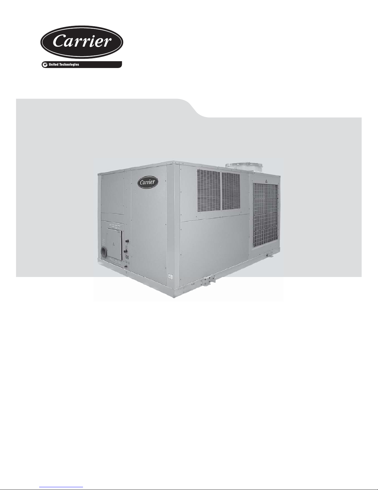
48EN/EH
Nominal cooling capacity 58,9 - 135,5 kW
Nominal heating capacity 62,2 - 143,4 kW
50 Hz
Packaged rooftop cooling only / heat pumps
with integrated gas burner
Original document
Page 2

Packaged rooftop units
with integrated gas burner
2
Contents
1. Introduction .......................................................................................................................................................................................................3
2. Operation limits .................................................................................................................................................................................................3
3. Technical characteristics ...................................................................................................................................................................................4
4. General recommendations ................................................................................................................................................................................5
Delivery of the unit ............................................................................................................................................................................................5
Unit identifi cation ...............................................................................................................................................................................................5
Documentation provided ...................................................................................................................................................................................5
Location .............................................................................................................................................................................................................5
Installation .........................................................................................................................................................................................................5
Unit maintenance ..............................................................................................................................................................................................5
Safety advice .....................................................................................................................................................................................................5
Refrigerant safety ..............................................................................................................................................................................................6
Burner safety .....................................................................................................................................................................................................6
5. Transport ...........................................................................................................................................................................................................6
Gravity centre ....................................................................................................................................................................................................7
6. Location and assembling ..................................................................................................................................................................................7
Location designation .........................................................................................................................................................................................7
Sound Level ......................................................................................................................................................................................................7
Anchorage for antivibrators ...............................................................................................................................................................................8
Minimum free space for commissioning and maintenance operations .............................................................................................................8
7. Gas Burner ........................................................................................................................................................................................................9
Operating principle ............................................................................................................................................................................................9
Control of the gas burner ................................................................................................................................................................................10
8. Safety elements ..............................................................................................................................................................................................11
Safety devices in the gas burner .....................................................................................................................................................................11
Safety devices in the 48EN/EH unit ................................................................................................................................................................12
9. Checking before commissioning .....................................................................................................................................................................13
Electrical Connections .....................................................................................................................................................................................13
Gas Burner ......................................................................................................................................................................................................13
Air ducts connections ......................................................................................................................................................................................15
Checks in the axial fans ...................................................................................................................................................................................15
Checks in the centrifugal fans .........................................................................................................................................................................15
Condensate drain connection .........................................................................................................................................................................16
10. Starting the unit ...............................................................................................................................................................................................17
Checks prior to commissioning .......................................................................................................................................................................17
Operational checks .........................................................................................................................................................................................17
Possible problems at commissioning ..............................................................................................................................................................17
11. Options ............................................................................................................................................................................................................18
Pre-assembly frames (optional) ......................................................................................................................................................................18
Outdoor coil protection grille ...........................................................................................................................................................................18
Filters ..............................................................................................................................................................................................................18
Stop-drop ........................................................................................................................................................................................................18
12. Maintenance ....................................................................................................................................................................................................19
13. Control and analysis of breakdowns................................................................................................................................................................22
Page 3
Packaged rooftop units
with integrated gas burner
3
1. INTRODUCTION
2. OPERATION LIMITS
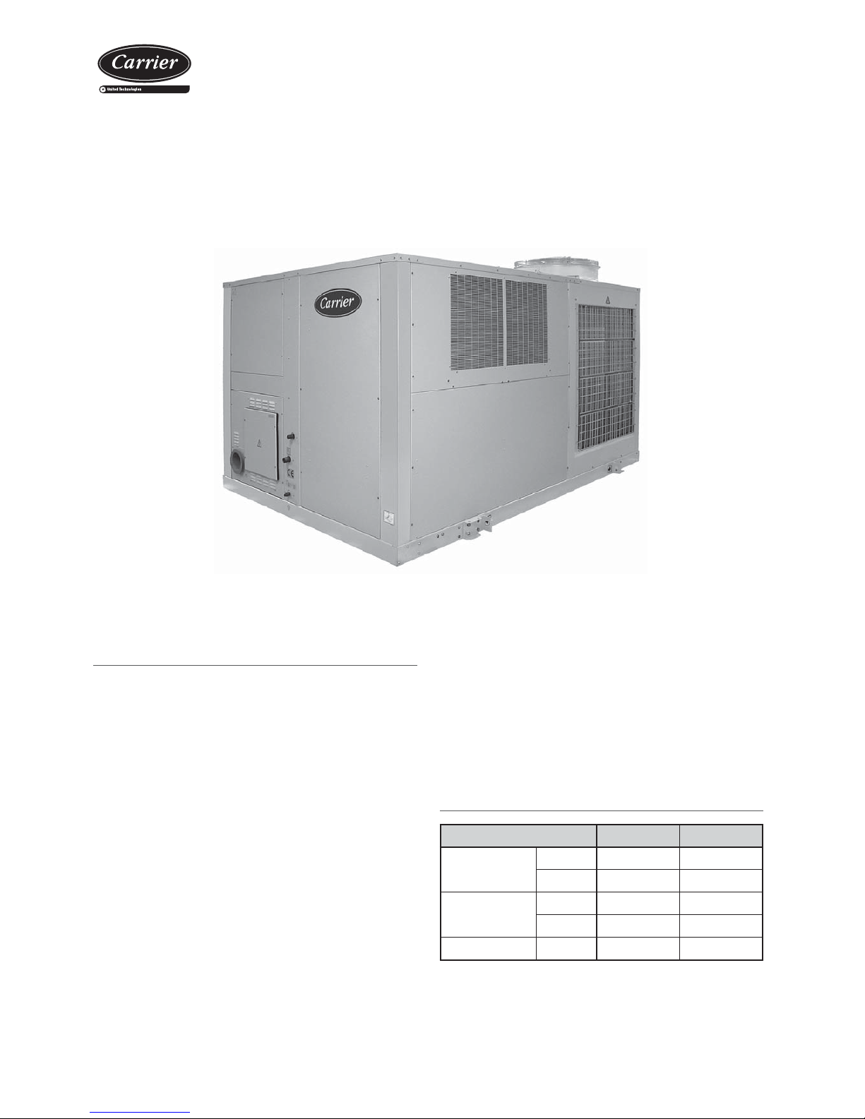
The 48EN/EH cooling units and heat pumps are autonomous air-air
units with a compact monoblock, horizontal rooftop design with a built
in natural or propane gas burner (in accordance with the gas Directive
90/396 EEC).
They are equipped with centrifugal and axial fans, air coils, hermetic
scroll compressors and electronic control with microprocessor,
components optimised for the R-410A refrigerant.
These units have been designed for the air conditioning of large surface
areas used for business or industry in areas with particularly low outdoor
temperatures in winter.
A vast number of options meet numerous operating demands thus
enabling quick installation and reliable operation.
Space 48EN Series
Autonomous air-air cooling units with a compact horizontal rooftop
design with a built in gas burner.
Space 48EH Series
Autonomous reversible air-air heat pump units with a compact
horizontal rooftop design with a built in gas burner.
After manufacturing, all units are charged with refrigerant and
are tested at the factory, verifying the correct operation of all
their components.
In this brochure are described the actions and safety norms for a
correct unit handling.
With a condensation pressure control operating down to -10ºC.
With high powered axial fan operating up to 52ºC.
With outdoor temperatures below -15ºC it is compulsory to select the anti-freeze
protection option for the electric panel.
Inlet air conditions Cooling Heating
Indoor coil
heat pump
Minimum 14ºC WB 10ºC
Maximum 22ºC WB 27ºC
Outdoor coil
heat pump
Minimum
12ºC
-10ºC WB
Maximum
48ºC
15ºC WB
Gas Burner
Minimum --
-30ºC
Page 4
Packaged rooftop units
with integrated gas burner
4
3. TECHNICAL CHARACTERISTICS
Cooling capacity calculated in accordance with the EN-14511 standard given for indoor temperature conditions 27ºC, 50% RH and 35ºC outdoor temperature.
Heating capacity calculated in accordance with the EN-14511 standard given for indoor temperature conditions 20ºC and 6ºC WB outdoor temperature.
Total power input by compressor and motorised fans under nominal conditions, calculated in accordance with the EN-14511 standard.
Climatic warming potential of a kilogram of fl uorinated greenhouse gas in relation to a kilogram of carbon dioxide over a period of 100 years.
48EN/EH 241 321 361 242 322 362 420 485 540 600
Cooling
capacities
Cooling capacity (kW)
58,9 72,1 82,7 60,3 73,6 84,8 101,7 110,3 123,3 135,5
Power input
(kW)
21,4 28,1 32,7 21,1 27,5 32,0 33,0 37,0 42,8 49,8
EER performance 2,7 2,6 2,5 2,9 2,7 2,6 3,1 3,0 2,9 2,7
Heating
capacities
Heating capacity (kW)
62,2 76,7 92,3 62,2 76,1 91,6 105,5 115,5 129,0 143,4
Power input
(kW)
18,2 21,8 26,6 17,4 20,9 25,5 31,2 35,3 39,1 43,6
COP performance 3,4 3,5 3,5 3,6 3,6 3,6 3,4 3,3 3,3 3,3
Outdoor circuit
fan
Nominal air fl ow (m3/h) 30.000 42.000
Available static pressure (mm.w.c) 4
Type Axial
Number 24
Diameter (mm) 2 x 800 2 x 630 + 2 x 800
Output (kW) 2 x 2,0 / 1,3 2 x 0,7 / 0,4 + 2 x 2,0 / 1,3
Speed (r.p.m.) 895 / 685
875 / 650
895 / 685
Outlet fan
indoor
circuit
Nominal air fl ow (m3/h) 12.000 14.300 15.900 12.000 14.300 15.900 18.000 18.200 20.400 24.000
Available static pressure (mm.w.c) 12 12 12 12 12 12 12 12 15 15
Type Centrifugal
Number / no. turbines 2 / 2
Motor output (kW) 2 x 1,5 2 x 2,2 2 x 3 2 x 1,1 2 x 2,2 2 x 2,2 2 x 2,2 2 x 2,2 2 x 3 2 x 4
Power input (kW) 2 x 1,13 2 x 1,67 2 x 2,11 2 x 0,93 2 x 1,35 2 x 1,68 2 x 1,70 2 x 1,74 2 x 2,40 2 x 3,42
Speed (r.p.m.) 847 939 995 762 829 870 708 713 790 860
Compressor
Type Scroll
Number of compressors 2
Number of circuits 2
Number stages 2
Oil type Copeland 3MAF 32cST , Danfoss POE 160SZ, ICI Emkarate RL 32CF, Mobil EAL Artic 22CC
Volume of oil (l) 2 x 3,3 2 x 3,3 2 x 6,2 2 x 3,3 2 x 3,3 2 x 6,2 2 x 6,2 2 x 6,2 2 x 6,2 2 x 6,2
Gas
burner
Gas type Natural or propane
Standard model PCH-72 PCH-200
Max. heating capacity (kW) 73 197
Pressure drop (mm.w.c) 11,4 16,2 20,0 5,7 8,1 10,0 12,8 13,1 16,5 22,8
Electrical
features
Electrical power supply 400 V / III ph / 50 Hz (±10%)
Power supply 3 Wires + Ground
Maximum
absorbed
current
Compressor(s) (A) 58,0 70,0 72,0 58,0 70,0 72,0 87,0 102,0 116,0 130,0
Outdoor fan(s) (A) 8,6 8,6 8,6 8,6 8,6 8,6 11,2 11,2 11,2 11,2
Indoor fan (A) 7,2 10,0 13,8 5,4 10,0 10,0 10,0 10,0 13,8 18,0
Control (A) 2,0 2,0 2,0 2,0 2,0 2,0 2,0 2,0 2,0 2,0
Total (A) 75,8 90,6 96,4 74,0 90,6 92,6 110,2 125,2 143,0 161,2
Refrigerant
Type R-410A
Global warming potential (GWP)
2.088
Charge (kg) 18,4 19,8 27,0 18,8 20,1 27,4 42,5 42,4 51,0 51,0
Environment impact (tCO2eq) 38,4 41,3 56,4 39,3 42,0 57,2 88,7 88,5 106,5 106,5
Dimensions
Length (mm) 3.326 3.926 4.816
Width (mm) 2.205 2.205 2.205
Height (mm) 2.095 2.095 2.095
Weight
(kg) 1.497 1.581 1.717 1.723 1.806 1.942 2.360 2.402 2.459 2.512
Condensates output Ø
1 1/4” adaptor
Page 5
Packaged rooftop units
with integrated gas burner
5
Unit identifi cation
All units bear, legibly and indelibly, a data plate located in a prime
space, with the following data:
4. GENERAL RECOMMENDATIONS
For the gas burner the unit includes a second nameplate with its
features:
Note: The serial number must be used in all communications
regarding the unit.
Delivery of the unit
Check the condition of the equipment upon delivery. Check that the
details on the label, the packing and the rating plate match the order.
If equipment has been damaged, or there is a shortfall in delivery,
notify accordingly.
Documentation provided
The following documentation is provided with the 48EN/EH unit:
- This brochure for the installation, operation and maintenance.
- Electrical diagram: this diagram must be consulted for the electrical
connections of the 48EN/EH unit.
- CARRIERrtc electronic control brochure.
- Communications brochure for the CARRIERrtc electronic control (in
case the 48EN/EH unit is connected to a pLAN network or to a BMS
monitoring system).
- Manufacturer's installation and maintenance brochure (APENGROUP)
for the burners in the PCH series.
- CE marking certifi cate.
- CARRIER warranty document.
Unit maintenance
The unit is to be inspected annually by a qualifi ed technician. He will
check all the gas and electrical connections and make sure that the
burner motor and safety devices and control systems are in good
working order.
Attention: In compliance with the requirements of the Gas
Directive 90/396 EEC it is strictly prohibited to alter the burner
or the electronic control unit.
Installation
The 48EN/EH units with built-in gas burner are to be installed in
accordance with the applicable gas unit regulations and norms in force
in the country of use.
Check that the supply, type, pressure and fl ow rate of the gas are
compatible with the specifi cations on the burner rating plate. For
safety and maintenance purposes, ensure that the aforementioned
specifi cations are observed.
Safety advice
T o avoid accidents during installation, commissioning or maintenance,
it is required to take into consideration the units specifications:
refrigerated circuits under pressure, refrigerant presence, voltage
presence and implantation.
Because of all of this, only qualifi ed and experienced personnel can
perform maintenance tasks or unit repairs.
It is required to follow the recommendations and instructions
in the maintenance brochures, the labels, and the specifi c
instructions. It is necessary to comply with the norms and
regulations in effect.
The compressor surfaces, the lines and hot components on
the gas burner can reach temperatures above 100ºC, causing
physical burns. In the same fashion, under certain conditions
these surfaces can reach very cold temperatures that can
cause freezing risks.
Use safety gloves and gloves whilst working. Be careful with
sharp parts or elements in the unit.
V-220005
V-220004
Caution: Before intervening in the unit, verify that the main
power to the unit is cut off. An electric shock can cause
personal damage.
Note: In order to recycle these units follow the stipulations
of directives (EC) No. 96/2002 and No. 108/2003 regarding
electrical and electronic equipment and the management of
the resulting waste.
Location
These units are prepared for rooftop installation. Make sure they are
not fi tted near areas where there is a risk of fi re (fl ammable dust)
or explosion, or in areas where aggressive products are kept, e.g.
trichloroethylene, perchloric acid, etc.
An.Year
CARRIER SCS
Route de Thil
01122 Montluel–France
Tél: 33(0)4 72 25 21 21
Ref. Produit
\Item Nb
r
Designation\Description
Refrigerant kW Absorbee\
Input
Poids\
Weight
Refrigerant kg Tension\Voltage Temperature Maxi C
BP Mini PSM
\MOP
Intensité\Current A
IP
HP Maxi PSM
\MOP
Int. Kit Elect.
No CE
0056
No Serie\Serial Nb
r
No Produit
Contains fluorinated greenhouse gases regulated by the Kyoto protocol
UTC BIS
P.I. Llanos de Jarata
14550 Montilla - SPAIN
Phone: 34 957 65 23 11
Made in Spain
COUNTRY
COUNTRY
m3/h
m3/h
GAS INFORMATION
GAS INFORMATION
GAS CONSUMMATION
GAS CONSUMMATION
GAS
GAS
GAS CATEGORY
GAS CATEGORY
PIN
PIN
GAS PRESSURE
GAS PRESSURE
TYPE
TYPE
mbar
mbar
CE certification
number of unit
with gas burner
WO
WO
Page 6
Packaged rooftop units
with integrated gas burner
6
5. TRANSPORT
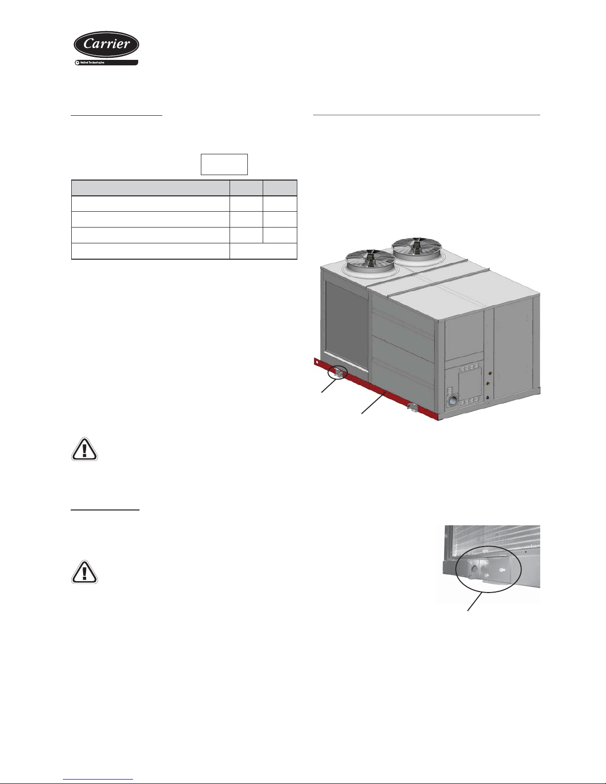
The unit must be handled with care to avoid transport damage. Thus
we recommend:
- For transport in a container, one must be selected that has an easy
load and unload to the installation location.
- Do not dispose of the pallet or the packaging materials until the unit
is in its fi nal location.
Note: the skis for closed container transport can be removed by
unscrewing them from the unit struts.
- The unit can be handled with a forklift truck, taking all necessary
precautions to avoid sliding of the unit on the truck's fork.
- The unit must be lifted and fi xed with care and without inclination
(maximum inclination 15º), since it could harm its operation. Please
refer to the gravity centre coordinates of each model in accordance
with the assembly.
- For the transport and lifting to the roof using a crane cloth slings
with rings will be used, with the
appropriate resistance, separated
by a strut to avoid damaging the
casing. These slings are attached
to the grips on the strut.
Detail lifting grip
Ski for the container
Refrigerant leaks:
- Toxicity: According to ASHRAE 34, R-410A belongs to the A1/A1group
with high safety both in the mix and also in the case of a leak.
- Although it is not toxic, in case of a leak to atmospheric pressure the
liquid phase evaporates. The resulting vapours are heavier than air
and can displace the technician local air. In case of an accidental
discharge in a closed enclosure, fans must be used to eliminate said
vapours.
- Although the R-410A is not fl ammable, when in contact with a fl ame
or hot spot it can decompose thus producing fl uor hydric acid HF and
fl uophosgene COF
2
which are highly toxic and corrosive.
- To detect leaks, an electronic leak detector, an ultraviolet lamp or
soapy water must be used . Flame detectors do not help.
Note: Repair immediately any refrigerant leak, using
recovery unit specifi c for R-410A that avoids a possible
mixture of refrigerants and/or oils.
Refrigerant safety
A periodical check must be performed for refrigerant gas leaks as per
Regulation (CE) Nº842/2006 over certain greenhouse effect fl uoride
gases.
R 410A
These units work with refrigerant gas
Components
R-32 R-125
Chemical formula CH2F2 CHF2CF3
Weight ratio 50% 50%
Unitary global warming potential (GWP) 675 3.500
Global warming potential (GWP) 2.088
Natural or propane gas leaks in the burner:
- Do not operate electric switches or other objects which could cause
sparks.
- Close the gas supply valve.
- Improve the ventilation if the burner is located in a closed area.
- Ensure that there is no one in the vicinity of the leak and request the
intervention of site staff.
Burner safety
The gas burner has a built-in maximum safety system which cuts off
the supply of gas to the burner should the fl ame go out. Ensure that
no objects impair the supply of air to the burner.
Note: If the generator is not going to be used over a
prolonged period the gas supply valve must be closed.
Grip
Attention: Check that the grips are perfectly screwed in before
attaching the slings.
- After the placing of the unit, it is recommended to remove the grips
as they can be a hindrance for maintenance. Put them back in case
of unit transport.
Page 7
Packaged rooftop units
with integrated gas burner
7
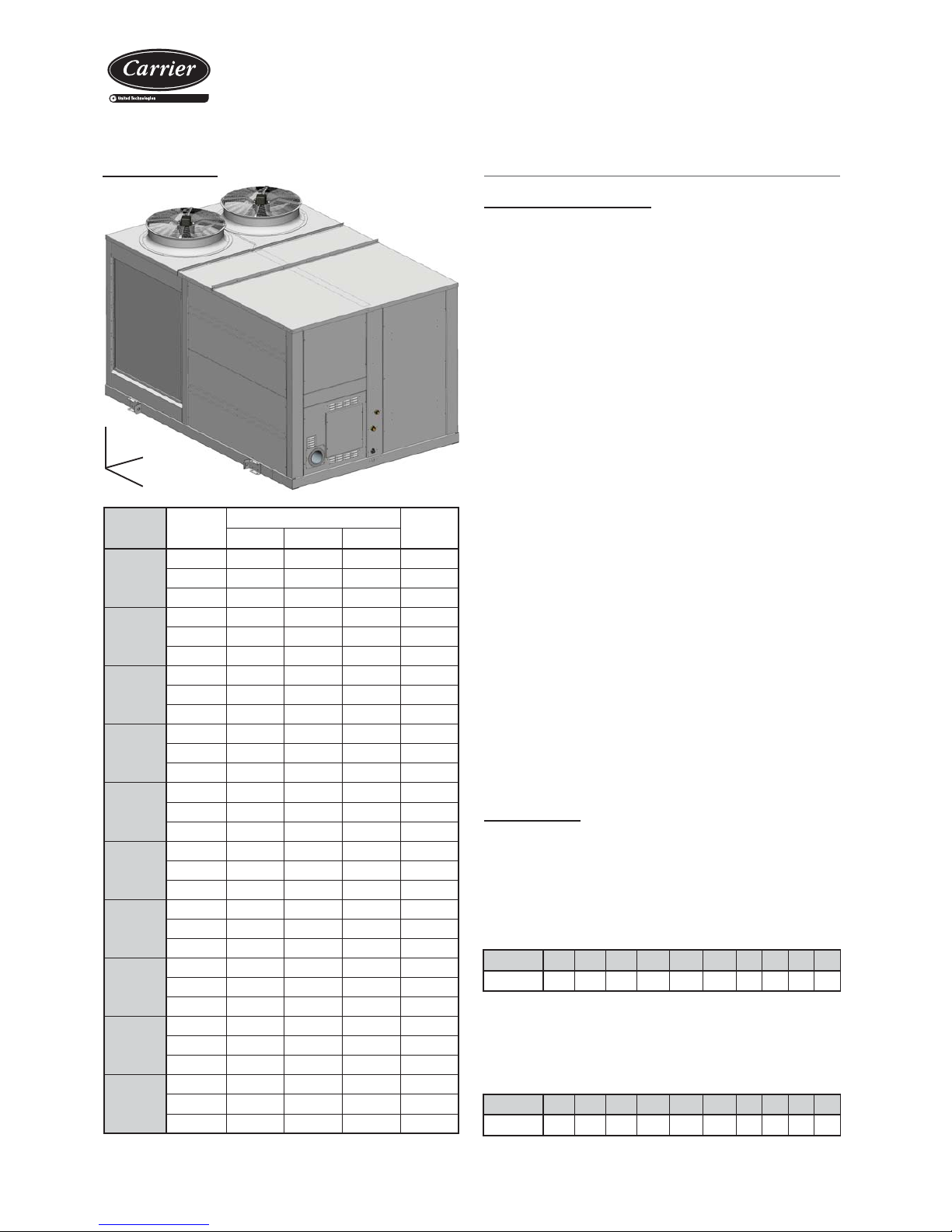
48EN/EH Assembly
Centre of gravity (mm)
Weight
(kg)
XYZ
241
MO 1062 1310 830 1497
MS 1127 1355 832 1578
MA / MC 0 1193 1385 804 1705
321
MO 1062 1310 830 1581
MS 1127 1355 832 1662
MA / MC 0 1193 1385 804 1789
361
MO 1062 1310 830 1717
MS 1127 1355 832 1798
MA / MC 0 1193 1385 804 1925
242
MO 1100 1300 845 1723
MS 1165 1345 847 1805
MA / MC 0 1223 1386 776 1925
322
MO 1100 1300 845 1806
MS 1165 1345 847 1888
MA / MC 0 1223 1386 776 2008
362
MO 1100 1300 845 1942
MS 1165 1345 847 2024
MA / MC 0 1223 1386 776 2144
420
M0 1024 2300 794 2360
MS 1085 2353 804 2458
MA / MC 0 1186 2469 746 2724
485
M0 1024 2300 794 2402
MS 1085 2353 804 2500
MA / MC 0 1186 2469 746 2766
540
M0 1024 2300 794 2459
MS 1085 2353 804 2557
MA / MC 0 1186 2469 746 2823
600
M0 1024 2300 794 2512
MS 1085 2353 804 2610
MA / MC 0 1186 2469 746 2876
The unit weight includes the burner installed as standard which matches the
heaviest one amongst those available.
Location designation
Before moving the unit, make sure that all panels are fastened in place.
Lift and lower with care.
When choosing the location, in any way the selected fashion, the
following precautions have to be taken into consideration:
- It is mandatory to comply with norm EN 378-3 on Safety and
Environmental Requirements. Part 3: "In situ" installation and
protection to people.
- The area where the unit will be located must be perfectly accessible
for cleaning and maintenance operations (check minimum free space
for maintenance). Leave enough space for air circulation around the
unit.
- Foresee appropriate damping devices throughout the installation to
ensure that noise and vibration transmission is avoided (refer to the
section "Anti-vibration Anchoring").
- Check that the structure can withstand the weight of the unit.
- Since the unit is designed to work outdoors, some specifi c installation
norms must be followed:
• The unit will be located on the roof of the premises. If it is foreseen
that it will work more on heating than on cooling, it is preferable to
direct the coil towards the sun. If little work on heating is foreseen,
choose North direction.
• Avoid placing obstacles in the air outlet or return. No obstacle may
impede the air aspiration into the coils. Do not fi x the outdoor coil
side in the predominant wind direction.
• Do not install the unit in a closed enclosure or in conditions that
originate air recirculation.
• The chosen location must not fl ood and must be above the average
height the snow reaches in that region.
• All models can be installed on the fl oor or on a brick frame or steel
profi le (see optional preassembly frames in chapter 11). In any
case, check that the unit is perfectly level.
6. LOCATION AND ASSEMBLING
Sound Level
These units are designed to work with a low acoustic level. In any case,
in the design of the installation the outdoor environment, the kind of
building for the noise transmitted in the air and the solid elements for the
vibration transmission must be taken into consideration for the acoustic
radiation. If necessary , commission a study by an acoustic technician.
Sound power level
Note: The sound power spectrums can be consulted in the technical brochure
for the 48EN/EH series.
Sound pressure level
Measurement conditions: in free fi eld, measured at a distance of 5
metres, directivity 2 and at 1.5 metres from the ground.
Note: The sound pressure level depends on the installation conditions and, as such,
it only indicated as a guide. Values obtained according to the ISO 3744 standard.
48EN/EH 241 321 361 242 322 362 420 485 540 600
Total dB(A) 90 90 91 88 88 89 94 95 95 95
48EN/EH 241 321 361 242 322 362 420 485 540 600
Total dB(A) 63 63 64 61 61 62 67 67 67 67
Gravity centre
Z
X
Y
Page 8
Packaged rooftop units
with integrated gas burner
8
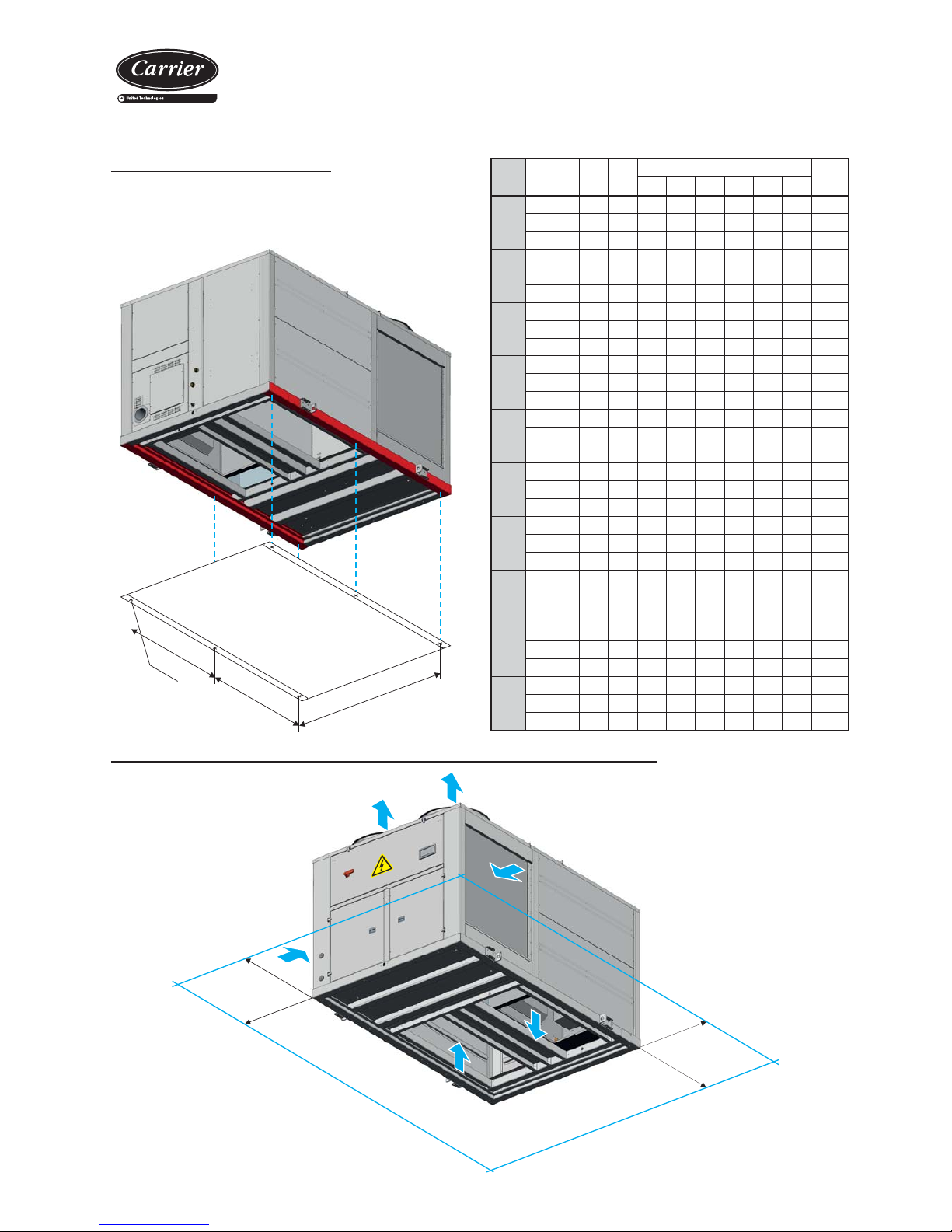
Anchorage for antivibrators
When selecting antivibration mounts both the unit weight and reactions
in the supports must be taken in account and are featured in the
following table.
48EN/
EH
Assembly
A
(mm)B (mm)
Reactions in the supports (kg)
Weight
(kg)
R1 R2 R3 R4 R5 R6
241
MO 1545 2095 100 349 271 119 368 290 1497
MS 1545 2095 133 384 290 121 372 278 1578
MA / MC0 1545 2095 170 433 323 121 384 274 1705
321
MO 1545 2095 105 369 286 126 389 306 1581
MS 1545 2095 140 405 306 127 392 293 1662
MA / MC0 1545 2095 178 454 339 127 403 288 1789
361
MO 1545 2095 114 400 311 137 422 333 1717
MS 1545 2095 152 438 331 137 424 317 1798
MA / MC0 1545 2095 192 489 365 136 433 310 1925
242
MO 1845 2095 69 412 378 70 413 380 1723
MS 1845 2095 102 450 404 66 414 368 1805
MA / MC0 1845 2095 137 498 438 63 424 364 1925
322
MO 1845 2095 72 432 397 74 433 398 1806
MS 1845 2095 107 471 423 69 434 385 1888
MA / MC0 1845 2095 143 520 457 66 443 380 2008
362
MO 1845 2095 78 464 427 79 466 428 1942
MS 1845 2095 114 505 453 74 465 413 2024
MA / MC0 1845 2095 153 555 488 70 473 406 2144
420
M0 2290 2095 250 536 306 309 595 365 2360
MS 2290 2095 298 582 328 312 596 342 2458
MA / MC0 2290 2095 409 689 373 337 616 300 2724
485
M0 2290 2095 254 545 311 314 605 371 2402
MS 2290 2095 304 592 334 317 606 347 2500
MA / MC0 2290 2095 415 699 378 342 626 305 2766
540
M0 2290 2095 260 558 318 322 620 380 2459
MS 2290 2095 310 605 341 325 620 355 2557
MA / MC0 2290 2095 424 714 386 349 639 311 2823
600
M0 2290 2095 266 570 325 329 633 388 2512
MS 2290 2095 317 618 348 331 633 363 2610
MA / MC0 2290 2095 432 727 394 355 651 317 2876
A
M12
A
B
Minimum free space for commissioning and maintenance operations
1500 mm
1500
mm
1500 mm
1500 mm
Page 9
Packaged rooftop units
with integrated gas burner
9
CO2 CONTROL
OFFSET
CONTROL
CALIBRATED
VENTURI
GAS INLET
TO THE BURNER
PRESSURE COCK
GAS INLET
models 150/200
CALIBRATED
VENTURI
CO2 CONTROL
PRESSURE COCK
GAS INLET
OFFSET
CONTROL
GAS INLET
TO THE BURNER
models 032/092
7. GAS BURNER
Flue
Air
Gas
EVP
EV2 EV1
Condensation
drain
for mod.150/200 only
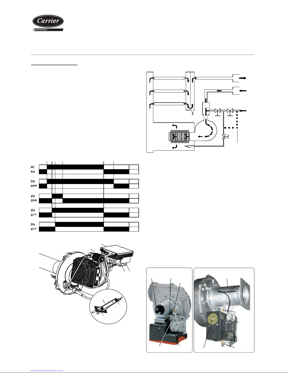
Operating principle
Connection / disconnection of the burner
When heating is required (A), the burner remote control starts the working
cycle of the modulation board which activates the fl ame control device.
This device starts up the burner combustion air fan (A), thus starting an
air current in the combustion chamber for a preset period of time.
When this phase has been completed the ignition cycle begins: the
electromagnetic valve EV1 opens at the same time as the EVP valve (B),
supplying the pilot burner. When the device detects the pilot fl ame it will
open the main gas valve EV2 (C) to supply the main burner.
The pilot and main burner will work together for a short period of time.
After this, the modulation board will close the electromagnetic valve
EVP (D) and disconnect the pilot burner.
The one electrode only guarantees the detection of the fl ame for the
pilot and main burner.
pilot burner
Burner group
EVP
EV1
EV2
detection
electrode
start-up
electrode
nozzle
Control device
On/off signal
Burner fan
EVP - pilot light flame
EV1 - 1st electromagnetic valve gas
EV2 - 2nd electromagnetic valve gas
ABC D E F
Operation of the air-gas premix
The air and the gas mix inside the vanes of the motor fan assembly.
The air inlet is achieved via a calibrated Venturi pipe from which the
gas is taken in.
The air/gas pressure ratio is 1:1 and can be adjusted by turning the
offset screw in the gas valve. The burner is supplied with the offset set
and the screw sealed.
The burner can also be regulated by adjusting the screw located above
the Venturi which establishes the maximum air fl ow rate value and, as
such, determines the carbon dioxide content in the condensates. This
screw is factory-set and must not be touched, although it is not sealed
thus allowing a changeover to another type of gas (before doing so this
must be consulted).
The modulation board installed in the burner regulates the fan speed (in
direct current) in accordance with the requirements of thermal capacity.
The gas fl ow rate changes at the same time as the variation in the motor
speed. The minimum and maximum values for the motor speed are
stipulated on the plate and cannot be changed.
The ignition cycle connects the burner to half capacity (approx. 70% of
its maximum thermal capacity). Two minutes after starting the burner
reduces its capacity to the minimum and as from this moment starts to
have modulating control (0-10Vdc) in accordance with the installation
requirements.
Page 10
Packaged rooftop units
with integrated gas burner
10
Control of the gas burner
T o establish the electric power supply of the unit (wire intake,
conductor section and their calculations, protections, etc.),
refer to the information provided in the technical catalogue
for the 48EN/EH units, the wiring diagram included with
the unit as well as the regulations and standards in force
that regulate the installation of air conditioning units and
electrical receivers.
Important: All the connections to be established by the client
are featured on the wiring diagram included with the unit.
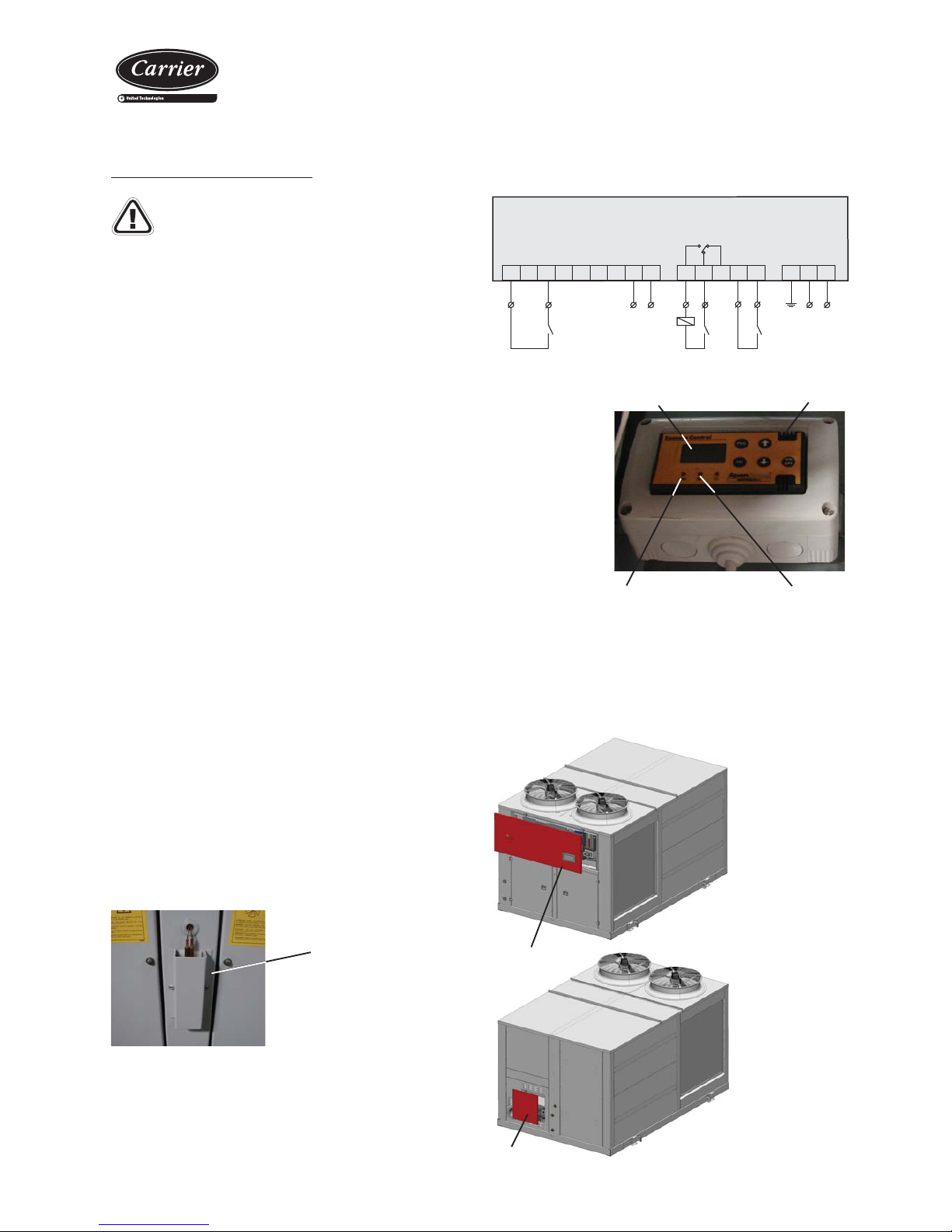
CARRIERrtc control
The CARRIERrtc control has a proportional output 0/10V (Y2) where
a natural gas or propane gas proportional actuator can be connected.
The control will manage its connection, in HEATING mode, through an
ON/OFF signal in digital output NO5.
- In cooling-only devices, the control will activate the burner the same
way as an electrical heater with one or two stages.
- In heat pump units it is possible to select three different methods for
controlling the burner for display:
• Operation of the compressors as one or two electrical heater
stages (both optional not compatible).
• Operation instead of the compressors.
• Operation instead of the compressors if the outdoor temperature
is less than the value set (5ºC by default).
When the return temperature drops below the value set for the burner
connection the burner will start to operate. The control of the power
will be carried out in accordance with the air outlet temperature and
the return temperature. The control will therefore compare both
temperatures and although there is a high burner power demand, if the
outlet temperature is excessively high it will limit the power supplied
by the burner. This avoids the stratifi cation of the hot air masses and
that the outlet air temperature exceeds a maximum safety level, 55ºC
by default, which will cause the burner to stop.
Moreover, units with gas burner always include a ambient temperature
probe to limit the difference between the air outlet pressure and the
ambient temperature and, with that, improve the feeling of thermal
comfort.
The gas burner integrates operations control and its safety devices.
The control CARRIERrtc will receive a safety signal from the burner in
the event of failure (digital input DI5), which will only serve to indicate
the failure.
Position of the outdoor
thermostat (located below
the 48EN/EH electric panel)
Wiring diagram:
The hose with all the wires required for the connection of the burner
control with the CARRIERrtc control must be wired in a box located
inside the 48EN/EH box.
230 Vac
RUN Signal
987654321 12111098 GNDLN
Burner remote control
On/Off
0/10Vcc
AL (DI5) Signal
N.O.
N.C.010
(Y2)
ON/OFF (NO5) Signal
Burner remote
control
Instantaneous voltage
display screen
Burner in operation
Unit switched on
On the burner
remote control
screen the
instantaneous
voltage transmitted
to the control plate
is displayed.
The burner remote control is also responsible for managing the safety
devices. In the event of failure the CARRIERrtc control will be sent a
failure signal by way of indication.
In addition to the burner’s safety devices, the CARRIERrtc control
allows incorporating complementary safety elements in the unit for the
detection of smoke, excessively high temperatures, loss in the air fl ow
rate etc. (consult the section on “Safety Devices”).
The connection of this hose is explained in the chapter “Burner
Installation”.
Access door
Main electric panel
(CARRIERrtc control)
Auxiliary electric panel
(burner remote control)
Access door
Page 11
Packaged rooftop units
with integrated gas burner
11
Supply of
air from the
48EN/EH
unit
Safety
thermostat
bulb (F2)
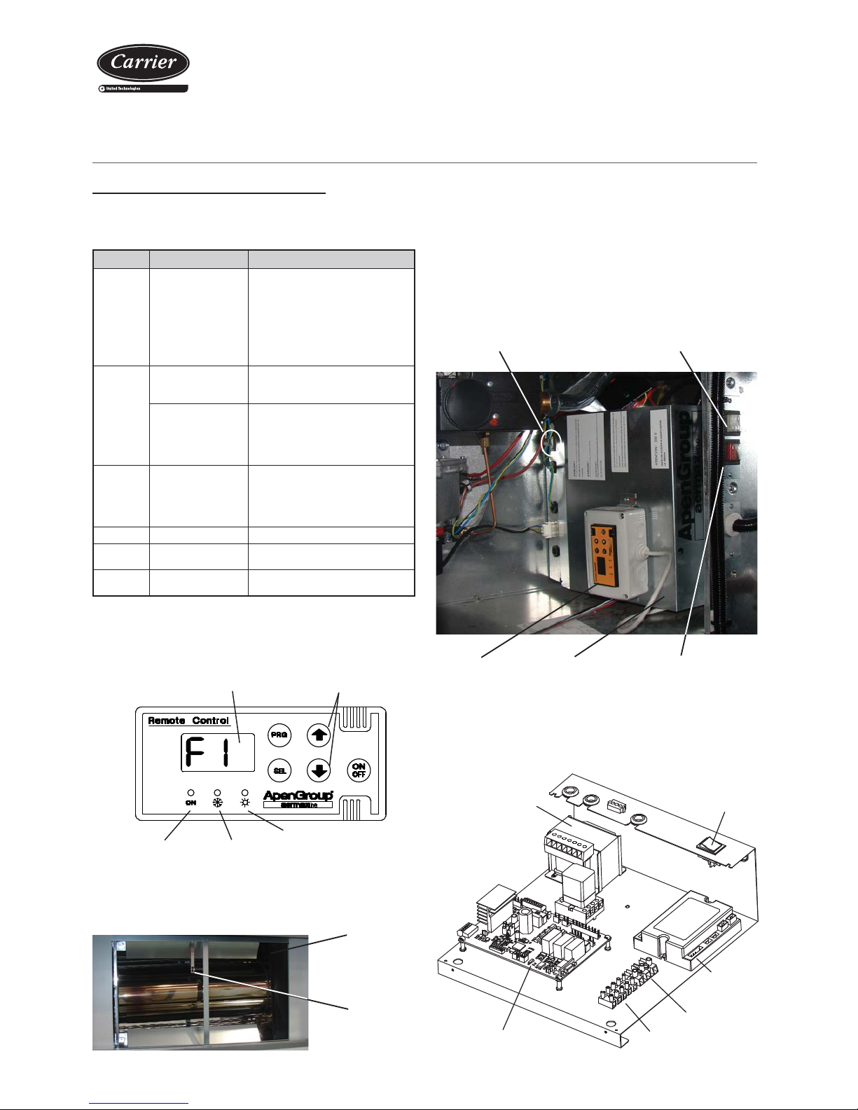
The F2 blocking can be triggered when the safety thermostat bulb detects
an excessive temperature in the inlet air to the burner. The following
fi gure shows the position of the aforementioned bulb:
The burner remote control manages the burner protection devices by
detecting and indicating the following operating faults on its display:
Safety devices in the gas burner
Indication Failure Problem
F1 The burner does not
start.
Reversed phase and neutral.
No gas supply.
Connection without neutral.
No ground connection.
Problems with the fl ame detection
electrode.
The electrode nozzle is dirty or its
diameter is incorrect.
F2 Safety thermostat High temperature in the exchanger.
Faulty thermostat bulb.
Presence of smoke.
Differential air
pressostat
The plastic conduit that enters the
pressostat is disconnected.
The discharge pipe and / or air inlet
pipe is (are) blocked.
Pressostat fault.
F3 The fan does not start The fan wiring is wrong or
disconnected.
The voltage values for the modulation
are outside the range.
Failure in the fan motor.
F4, F5, F6 Unused
F7 No serial
communication
The remote control is disconnected.
F8 The fl ame control
device does not work
The fl ame control device is
disconnected or broken.
To unblock press
both keys for 3 seconds
The screen displays a fault
Green led: this indicates that
the unit is switched on
Unused
Red led: this indicates that the
burner is switched on
Blocks F1, F2, F3 and F8 are triggered by safety devices and require
manual resetting. T o unblock press the up and down keys for 3 seconds
at the same time.
8. SAFETY ELEMENTS
Signalling pilot for
the switched on unit
Signalling pilot for
burner blocking
Transformer 230V/24V
Electronic modulation
Power supply
Connection for display
General switch
Flame
control
device
In order to access the gas burner control remove the door from the
auxiliary electric panel:
Burner remote
control
Gas burner switch
By removing the support box for the remote control access is gained
to the modulation board (0-10Vcc) and to the fl ame control device:
Support
box
In the event of failure, the burner control will send the CARRIERrtc
control a safety signal which will only be used as an indication (see the
electrical connections diagram in the previous chapter).
Page 12
Packaged rooftop units
with integrated gas burner
12
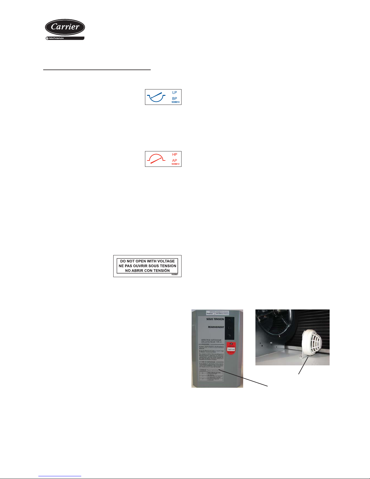
Main door switch
By using a mechanical device,
it impedes access to the electric
panel when the unit is with
voltage.
High pressure pressostat
Connected to the compressor discharge, it will
stop its operation when the pressure at that point
reaches the setpoint. It disconnects at 42 bar and
it is automatically reactivated.
Low pressure pressostat
When connected to the compressor suction, it
will stop its operation when the pressure at that
point goes down below the tare value (caused by
obstructions in the circuit, excessive dirt in the fi lters, fan stop or ice
formation in the evaporator).
It disconnects at 2 bar and it is automatically reactivated.
Safeties at the compressor
The scroll type compressor that these units as standard have the
following safeties:
- Non-return valve built into the compressor.
- Klixon in the compressor, which stops the operation of the motor
when there is excessive heating.
Condensation and evaporation pressure control
This safety element, integrated in the control, enables managing the
outdoor fans when the units are working in COOLING mode with low
outdoor temperatures (condensation control) or in HEATING mode with
high outdoor temperatures (evaporation control).
This aids the unit's operation in all the stations.
Smoke detector (optional)
This smoke detection station uses a LED to indicate the installation
status and if the probe detects the presence of smoke in the installation
it stops the operation of the unit. The station is installed in the factory
in the auxiliary electric panel.
Smoke detecting station
Smoke detecting probe
Clogged fi lter detector (optional)
Differential pressostat for indication of maintenance to fi lters. Automatic
reactivation. It is installed in the auxiliary electric panel.
Anti-fi re safety device
This safety device, integrated in the control, shuts down the unit if the
probe located in the return detects an air inlet temperature above
60ºC. The unit will not return to operation until this temperature drops
under 40ºC.
Control of air fl ow
Differential pressostat that measures the fl ow variation in the air outlet.
This allows the detection of fan belt breakages, since the fan relay only
detects operating faults that have arisen in the motor. This pressostat
is installed in the factory in the auxiliary electric panel.
Protection of the electric panel (optional)
Anti-freeze protection for low outdoor temperatures with electric heater.
This safety device is compulsory when the outdoor conditions guarantee
an air inlet temperature to the burner which is less than -15ºC.
Air quality probe (optional)
This probe is for installation in the environment or in duct to enable
measuring CO2 and/or volatile compounds.
This probe is to be connected by the client. The clamps on the terminal
board on the main panel used for the connection are indicated on the
wiring diagram provided with the unit.
This probe is supplied inside the main electric panel.
Automatic switch in the control circuit
Magnetothermal switch that protects the operation circuit against
continuous surges as well as against high currents of short duration
(short circuits).
Defrost control
This safety element is intended to eliminate ice which could accumulate
in the outdoor coil when the unit is working in the heating CYCLE.
Defrosting is carried out by the control depending on the value
measured by the sensors on the outdoor coils and the time set between
defrosting operations.
Magnetothermals for line protection
They are located at the beginning of the power lines of the compressor
and motorised fans to protect them.
Safety devices in the 48EN/EH unit
Page 13
Packaged rooftop units
with integrated gas burner
13
9. CHECKING BEFORE COMMISSIONING
Note: Under no circumstance should the unit be started without having read the brochure completely.
Gas Burner
Caution: During the installation work and when adjusting
the burner the gas pipe must be unloaded.
Electrical Connections
Note: All the connections to be established on site are the
responsibility of the engineer and are indicated on the unit
wiring diagram.
T o prevent electrical shocks, make all electrical connections
before energizing the unit. Check that the automatic switch
is closed. Omitting this can cause personal damage. Make
the ground connection before any other electrical connection.
V-220004
V-220004
The installer must fi x line protection elements according to
the effective legislation.
Before putting the unit into operation also check the following:
• Check the condition of the electrical connections and that they are
correct (an electrical diagram is included with each unit, along with
its legend).
• That the electrical power supply remains constant and that it
corresponds to that featured on the unit data plate.
• That they are no cables close to heat sources.
• The correct connection of all the sensors supplied with the unit. The
connection of the outlet temperature and ambient temperature probes
must be established on-site. These probes are supplied inside the
main electric panel.
In order to establish the unit's electric power supply (cable inlet,
calculation of the lead section, protection devices etc.), refer to:
- The information supplied in this document (table of technical
characteristics).
- Data plate.
- The wiring diagram and the legend supplied with the unit.
- The CARRIERrtc electronic control brochure which is also supplied
with the unit.
- The regulations and norms in force which regulate the installation of
air-conditioning units and electric receivers.
The electric power supply of the unit must be sized in accordance
with the maximum power absorbed by the unit taking into account all
the options it features (if necessary, refer to the technical brochure).
- With regard to the electric supply, check:
• The correct neutral and phase connection. If they are reversed
the fl ame control prevents operation.
• The correct adjustment of the burner control and regulation
devices.
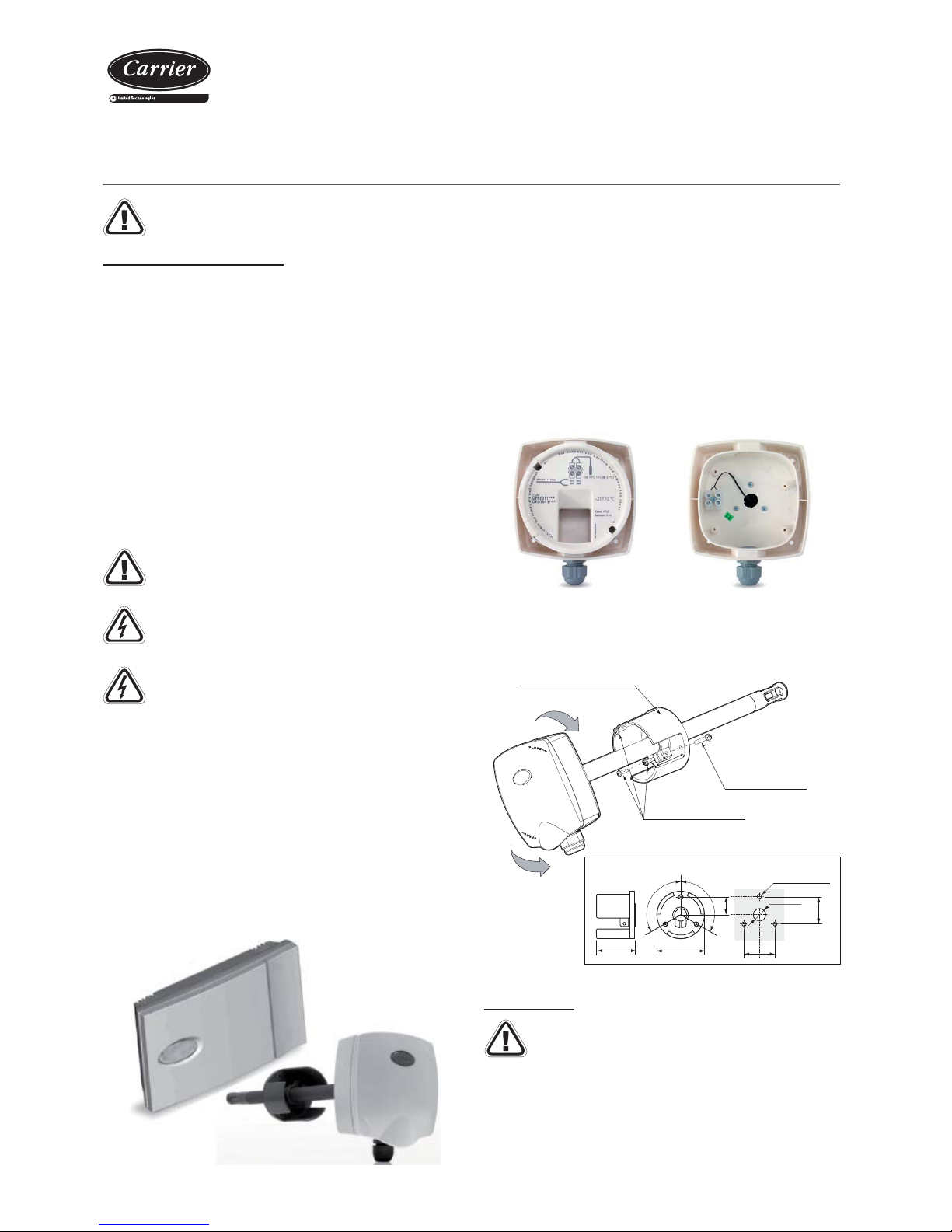
ambient probe
outlet probe
Connection of the outlet temperature probe:
In order to guarantee the correct measurement of the outlet air
temperature this probe will be positioned at 1.5 metres as a minimum
from the outlet mouth at the bottom of the duct and as near to the
middle as possible inside this duct.
The connection of the probe to the corresponding clamps on the
control board (see wiring diagram) will be carried out with a cable
with two wires measuring 1mm2.
3 x M3x10 self-tapping male
Rotate to open
Rotate to close
Clamp for attaching to the duct
Screw to fix the probe
position (PT3.5x12)
61
120°
120°
25
42
No. 3 holes Ø 2.75
Ø 17
37,5
43,3
==
Detail of clamp dimensions (mm)
View of the probe without cover
(rotate the cover anti-clockwise)
View of the probe interior (connection
of 2 wires in the terminal board)
In order to fi x the probe to the duct a clamp will be used which is
supplied with the probe as shown in the fi gure below:
Page 14
Packaged rooftop units
with integrated gas burner
14
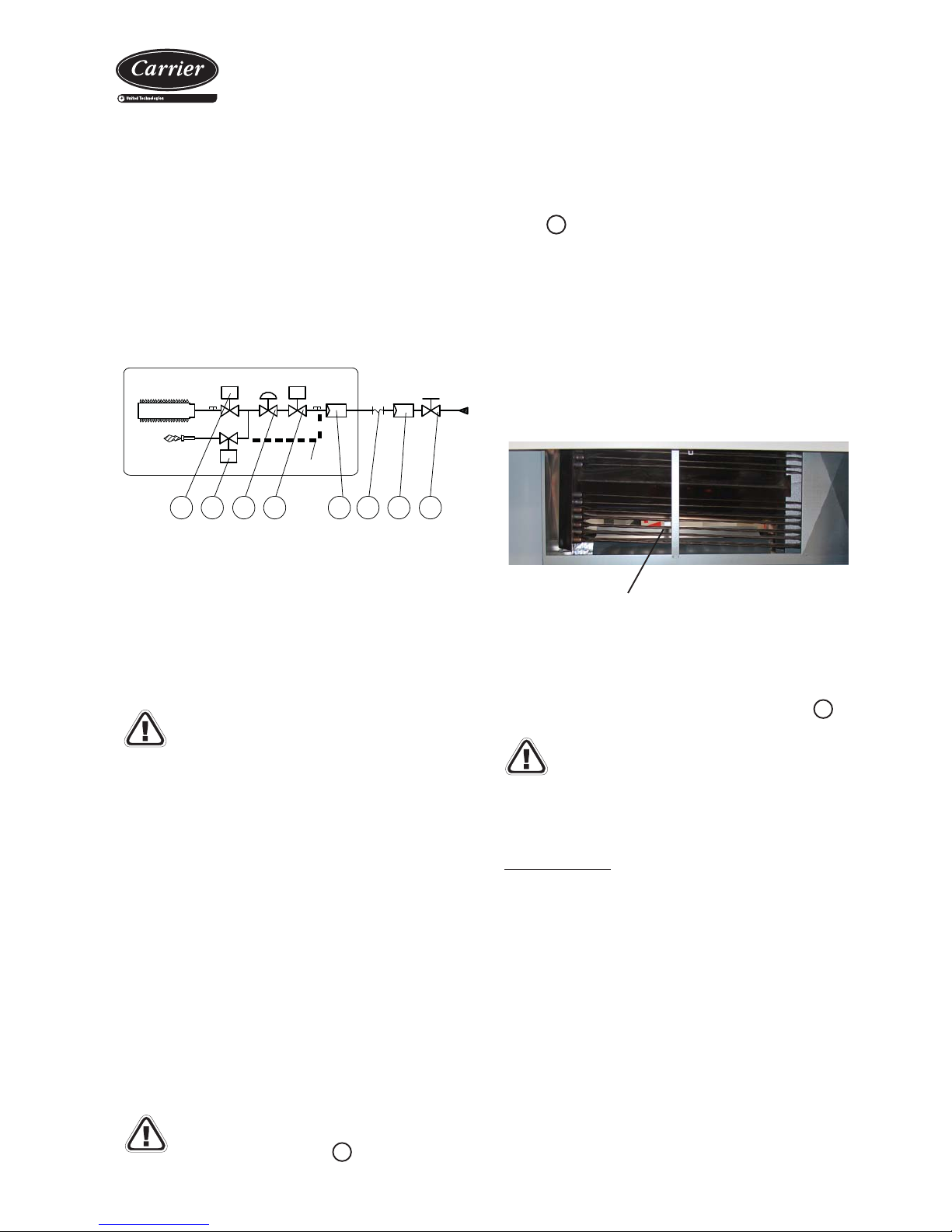
1 2 3 4 5 6 7 8
PCH150/200
Included in the burner module
Where:
1. Solenoid valve main burner (EV2)
2. Solenoid valve pilot burner (EVP)
3. Pressure stabiliser:
4. Solenoid safety valve (EV1)
5. Gas fi lter (small section)
6. Vibration damping gasket
7. Gas fi lter (large section)
8. Gas cock
- With regard to the gas supply:
The burner module includes the following elements: solenoid valves,
stabiliser and safety valve (see diagram).
To complete the installation a gasket must be fi tted to dampen
vibrations and a gas cock. It is also obligatory to install a gas fi lter
with certifi cation EN126 with a fi ltering level less than or equal to
50 microns, without pressure stabiliser for a high fl ow due to being
assembled as standard with the gas valve.
For the gas power supply the burner has a bronze M 1" threaded
drain junction.
Note: If the generator is not going to be used over a
prolonged period the gas supply valve must be closed.
Chimney connection:
As a general indication, the chimney mouth must be located, as
a minimum, 1 metre above the highest point of roofs, walls or any
other distant obstacle at less than 10 metres. If the chimney mouth
is located at a distance between 10 and 50 metres from any building
it must be at a level of no less than the upper edge of the highest
gap in the nearest building.
The materials used for the manufacture of the chimney are:
- Aluminium with a minimum thickness of 1.5 mm.
- Stainless steel with a minimum thickness of 0.6 mm (carbon
content <2%).
Pipes with hermetic gaskets should be used to prevent any
condensate leak. These gaskets must be prepared for working over
a temperature range of 30ºC to 160ºC.
These pipes must also be insulated to protect those who could
accidentally touch them from burns.
Note: The gas burner chimney is not supplied with the
unit. Its design and installation is the responsibility of
the engineer and must comply with all the directives and
regulations in force in the installation location.
- With regard to the smoke outlet:
Smoke outlet connection type: category B23. Inside diameter of the
connection 146 mm andoutside diameter 210 mm (symbol
6
).
- With regard to the fuel, check that:
• The gas supply network information is compatible with that
indicated on the data plate and that the generator is supplied with
the same type of fuel for which it has been manufactured.
• The aspiration of combustion air and the expulsion of smoke are
free (presence of dirt, leaves etc.)
• The unit air fl ow rate is appropriate according to the data plate
and the unit includes all the required safety elements in perfect
condition.
• The fuel supply pressure is within the interval featured on the data
plate.
• The supply line valves are open.
• There are no leaks in the gas line.
- With regard to the collection of condensates:
These units are equipped with a junction for draining the burner
condensates drain pan. Threaded connector M 3/4” in PVC (see
symbol
3
in the following fi gure).
T o facilitate drainage, the construction of the group of generator pipes
slopes slightly towards the discharge.
If the unit is going to be installed outdoors in a location where there
are never low temperatures, the drain junction does not have to be
connected to any pipe. It must simply be ensured that the water
does not stagnate.
If the condensates are going to be discharged into a pipe do not seal
it directly at the condensate outlet. If the water were to freeze in the
pipe this could block the discharge of condensates and cause the
water to accumulate inside the exchanger.
Group of sloping pipes
Note: The access panel to the burner includes two grilles
for the recirculation of outdoor air in the case of a gas leak
inside the module (see symbol 4 in the following fi gure).
Page 15
Packaged rooftop units
with integrated gas burner
15
The air outlet and return ducts must be calculated in accordance with
the nominal fl ow and the unit's available pressure (refer to the technical
characteristics table). The duct calculation and design must be made
by qualifi ed technical personnel.
It is advisable to take into consideration the following recommendations:
- Bends in the discharge outlet must be avoided. It is recommendable
to have a straight section of duct measuring approximately 1 metre.
If it is not possible, they must be as smooth as possible, using indoor
defl ectors when the duct is of large dimensions.
- When making the ducts, abrupt changes in direction must be
avoided since they can cause occasional pressure drops which
affect the available pressure and the fl ow. The location of discharge
and aspiration grilles must be studied carefully to avoid the air
recirculation and the transmission and generation of noises to the
interior.
- Flexible connections must be made between the ducts and the unit
that avoid the noise and vibration transmission.
Air ducts connections
Checks in the axial fans
- Before commissioning, check the blade rotation direction and that
the axis turns without strokes nor vibrations
- Once running, check the operation conditions: pressures, fl ows and
consumptions.
- With electronic fans (optional) check that in COOLING mode they
adapt their speed according to the condensation pressure and in
HEATING mode according to evaporation pressure.
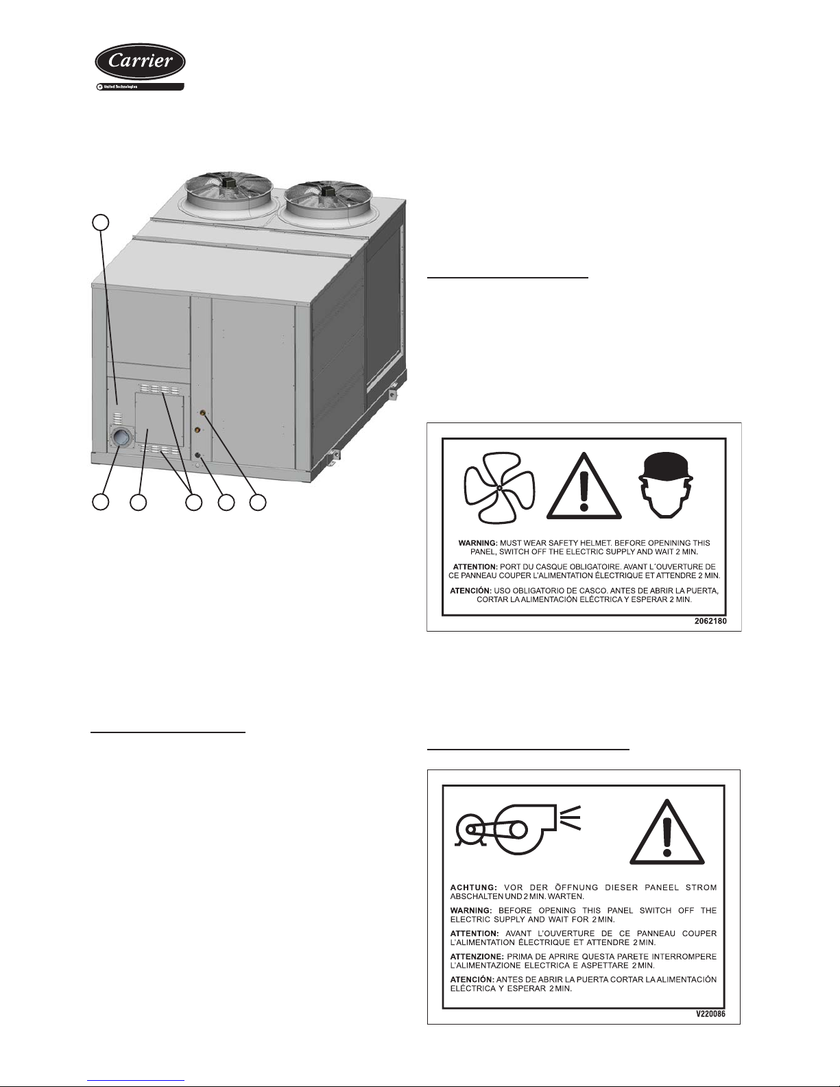
6
Where:
1. Air inlet grilles to the burner (its design takes into account the removal
of rainwater to the outside using the lower grille)
2. Gas power supply, junction M1"
3. Removal of burner condensate, junction M 3/4”
4. Grilles for the recirculation of outdoor air
5. Access panel to the auxiliary electric panel and to the burner remote
control
6. Chimney connection (by the customer):
Indoor: 146 mm yOutdoor: 210 mm
1
5 4 3 2
The following fi gure shows the gas burner connections: - No matter the type of ducts type to use, they must not be composed
of materials that propagate fi re nor expel toxic gases in the event of a
fi re. The internal surfaces must be smooth and should not pollute the
air that circulates within them. In any case, the effective legislation
in this respect must be observed.
Checks in the centrifugal fans
Page 16
Packaged rooftop units
with integrated gas burner
16
Condensate drain connection
Siphon installation norms
- Check that the condensate outlet is not clogged.
- All water drain tubes must be provided with a siphon to avoid bad
smell and water spills.
Perform the assembly as per the scheme of the attached starting
diagram:
Pan in overpressure:
• It is installed to avoid the access through the drain tubing of bad
smells.
All the models are equipped with
a junction for the draining of the
condensates drain pan from the indoor
circuit. Drain joint, made of bronze, gas
thread M 1 1/4".
With outdoor temperatures which are lower than 0ºC the
necessary precautions must be taken to prevent the water in
the drain ducts from freezing.
CONNECT SIPHON
METTRE SIPHON
PONER SIFON
V220014
Check the connection air tightness.
A
Condensates pan
in depression
A
Siphon drain
Slight slope
5/1000
To drainage
Pan in underpressure:
Besides the previous application, water must be sucked from the pan:
• For the correct siphon design, the "A" height must be at least twice
that of the underpressure (mm.w.c) where the condensates pan
is placed.
• The drain tubing must be slightly sloped to ease circulation towards
the drain.
• The original diameter of the tube must be respected. No reduction
can be made.
Condensates
outlet
- Before commissioning, check the blade rotation direction and that
the axis turns without strokes nor vibrations.
- Once running, check the operation conditions: pressures, fl ows and
consumptions.
- The coupling of characteristic bends of the fan and the room is
very important, so that the fl ows and pressures provided to the duct
network are as required.
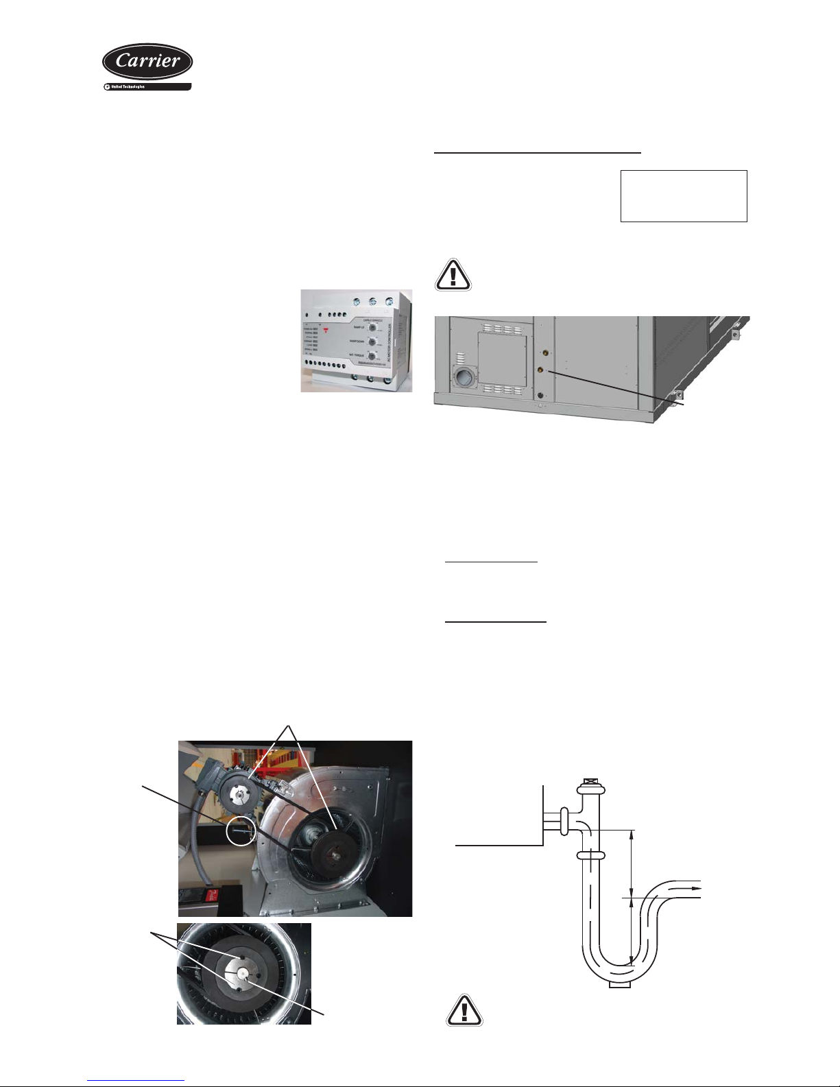
Pulley and belt adjustment
Centrifugal motorised fans in the indoor circuit are coupled using
pulleys and belts. In this type of fans, the following must be taken into
considerations:
- The pulleys must be on the same plane, so it is important to check
them with the help of a ruler or a laser aligner.
- In case they are not, remove the pulley screws, remove the pulley
and, after removing the hub pin, it can be slided over the axle (this
action can be performed both in the motor as well as in the fan).
- After fi xing the pulleys on the same plane, the belt tension is made
by tightening the tensor screw.
- The belt tension must be checked after 24 hours of motor operation.
Attention: Before performing these operations, it is necessary to verify
that the unit is disconnected from mains.
Pulleys must stay on the same plane
Tensor
screw
Pulley
screws
Taper pin
• Soft starter detail (optional):
The soft starter of the outlet fan extends
the time to reach its regular speed. This
is mainly intended for installations with
fabric ducts.
It is installed in the factory in the auxiliary
electric panel for motors up to 15kW.
Page 17
Packaged rooftop units
with integrated gas burner
17
- When starting the compressors, check the subcooling and overheating
and thus verify if the refrigerant load is appropriate
to the operating conditions. To adjust the
refrigerant load, a schrader valve is available on
the liquid line.
- Verify the absence of any leaks of the refrigerant.
- Check the unit operation and verify the safety elements.
- All the 48EN/EH models are
equipped with scroll type
compressors and have a phase
control relay. Verify that they
turn in the correct direction and,
if not, reverse the power wires.
10. STARTING THE UNIT
R 410A
Operational checks
Check the unit operation by verifying the electronic control and the
safety elements.
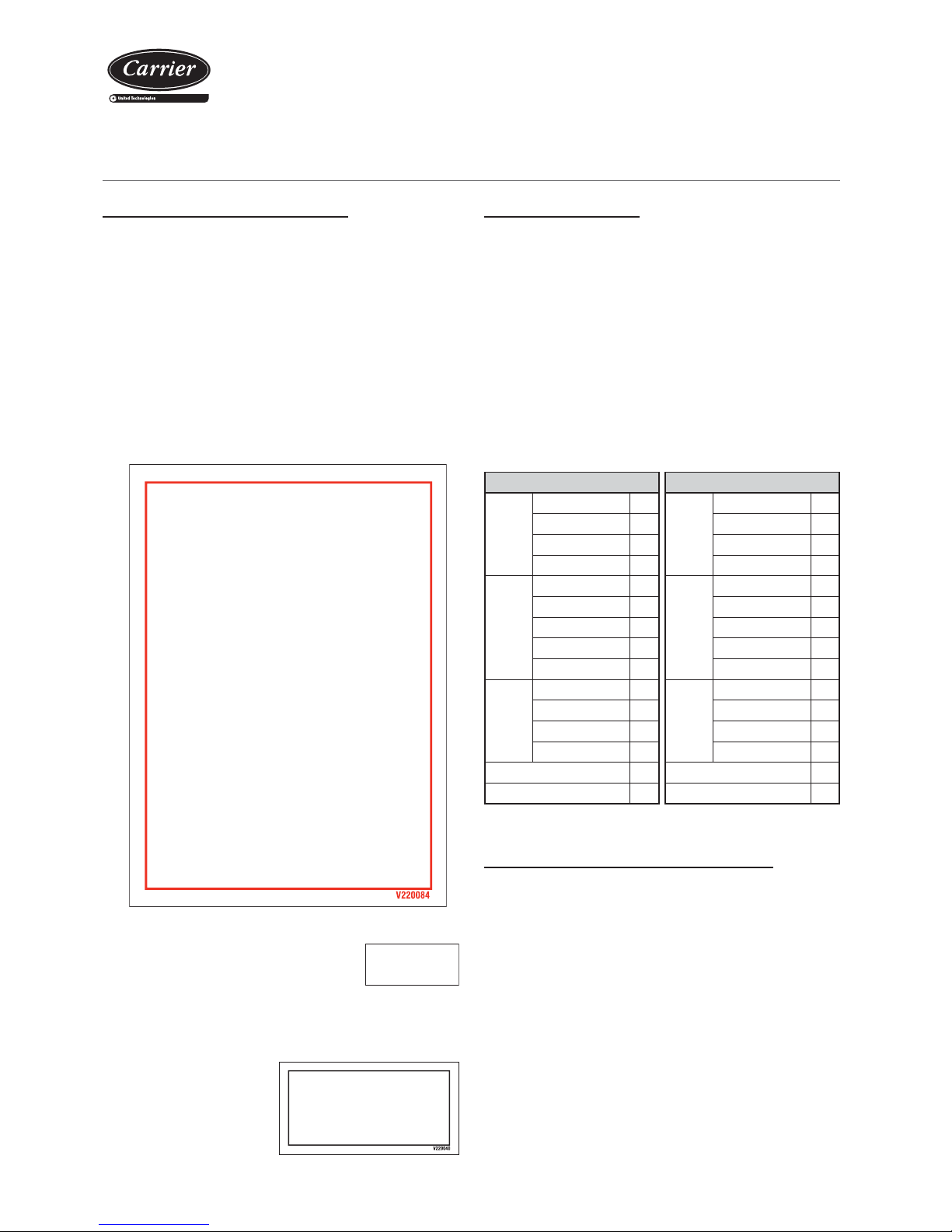
It is also recommendable to create a report, taking note of the date,
which includes the following information: the nominal voltage, current
absorbed by the compressors, fans and other electrical components,
signifi cant temperatures in the cooling circuit (see table below) and
other aspects considered interesting such as alarms detected by the
electronic control of the unit. The recording of these parameters whilst
the unit is running allows controlling the installation performance and
it is the best possible way to avoid breakdowns since the analysis
of these data makes early detection of anomalies possible or the
provision of the necessary means available to ensure that they do
not take place.
Possible problems at commissioning
All indications given in this brochure must be respected and
complied with to guarantee a correct operation of the units.
Next, several possible operation problems are stated which could
happen if the conditions of the commissioning are not appropriate.
- Air fl ow lack: very high differences between inlet and outlet, originated
by a high pressure drop in the ducts, or by other causes that impede
the correct air circulation.
- Air recirculation in the unit, originated by some obstacle in the air
aspiration or outlet.
- Noise problems because of excessive air fl ow in the grille.
- Water overfl owing to the pan problems, originated by an excessive
fl ow, an incorrect siphon installation or because a defective unit level.
- Refrigerant circuit humidity problem, because of an incorrect vacuum
realization.
Checks prior to commissioning
- It is advisable to make a complete sketch of the installation including
the location of the unit and all the components used. This will be very
helpful for maintenance and repairs to the installation.
- Check that the electrical power supply matches the unit voltage and
that its value lies within acceptable limits.
- It must also be verifi ed that the electric installation has been carried
out according to the electric wiring diagram provided with the unit
(consult the chapter on “Checking before commissioning”).
- Once the above verifi cations have been carried out, the control
circuit is supplied with voltage by the automatic control switch. It is
necessary to leave with voltage the compressor crankcase heater
for 24 hours before starting the compressor.
WICHTIG: WIEDERBEHEIZUNG DER
OLWANNE
IMPORTANT: CRANKCASE HEATING
IMPORTANT: SURCHAUFFE CARTER D’HUILE
IMPORTANTE: RISCALDARE IL CARTER
DELL’OLIO
IMPORTANTE: RECALENTAMIENTO DE
ACEITE DEL CÁRTER
KOENNEN.
TO ALLOW THE COMPRESSOR(S) STARTING
AU PREMIER DÉMARRAGE OU APRÈS UNE ABSCENCE
TENSION 24 HEURES AVANT D’AUTORISER LE
DÉMARRAGE DU(DES) COMPRESSEUR(S).
AL PRIMO AVVIAMENTO U DOPO UNA INTERRUZIONE
PROLUNGATA DELLA ALIMENTAZIONE ELETTRICA,
LASCIARE LA MACCINA SOTTO TENSIONE PER 24 ORE
PRIMA DI AUTORIZZARE L’AVVIAMENTO DEL(DEI)
COMPRESSORE(I).
ANTES DEL PRIMER ARRANQUE O DESPUÉS DE UNA
AUSENCIA DE CORRIENTE POR UN LARGO PERIODO DE
TIEMPO, CONVIENE QUE LA UNIDAD ESTÉ CONECTADA
UN MÍNIMO DE 24 HORAS.
BEIDER ERSTEN INBETRIEBSETRUNZ ORDER NACH EINER
LANGEN STROMUNTER-BRECHUNG BRINGEN SIE DIE
MASCHINE UNTER SPANNUNG 24 STRUNDERLANG
BEVOR SIE DEN(DIE) KOMPRESSOR(EN) EINSCHALTEN
FOR THE FIRSTSTART OR AFTER ALONG TIME OUT OF
VOLTAGE PUT THE MACHINE ON LIVE 24 HOURS BEFORE
DE COURANT PROLONGÉE, METTRE LA MACHINE SOUS
COMPRESOR SCROLL.
COMPROBAR SENTIDO DE GIRO
COMPRESSEUR SCROLL.
VÉRIFIER LE SENS DE ROTATION
SCROLL COMPRESSOR.
CHECK SENSE OF ROTATION
COOLING mode HEATING mode
Compressor
Suction pressure bar
Compressor
Suction pressure bar
Suction temp. (1) ºC Suction temp. (1) ºC
Condens. pressure bar Condens. pressure bar
Condens. temp. (2) ºC Condens. temp. (2) ºC
Air
condenser
Gas inlet temperature ºC
Air
evaporator
Gas inlet temperature ºC
Gas outlet temp. (3) ºC Gas outlet temp. (4) ºC
Air inlet temperature ºC Air inlet temperature ºC
Outdoor temperature ºC Outdoor temperature ºC
Air outlet temperature ºC Air outlet temperature ºC
Air
evaporator
Air inlet temperature ºC
Air
condenser
Air inlet temperature ºC
Air outlet temperature ºC Air outlet temperature ºC
Gas inlet temperature ºC Gas inlet temperature ºC
Evap. outlet temp. (4) ºC Gas outlet temp. (3) ºC
Subcooling (2) - (3) ºC Subcooling (2) - (3) ºC
Overheating (4) - (1) ºC Overheating (4) - (1) ºC
Page 18
Packaged rooftop units
with integrated gas burner
18
Pre-assembly frames (optional)
The units can be attached to standardised preassembled frames
with adjustable height, built in galvanised steel panelling with thermal
insulation.
For more information please consult the specifi c brochure for the
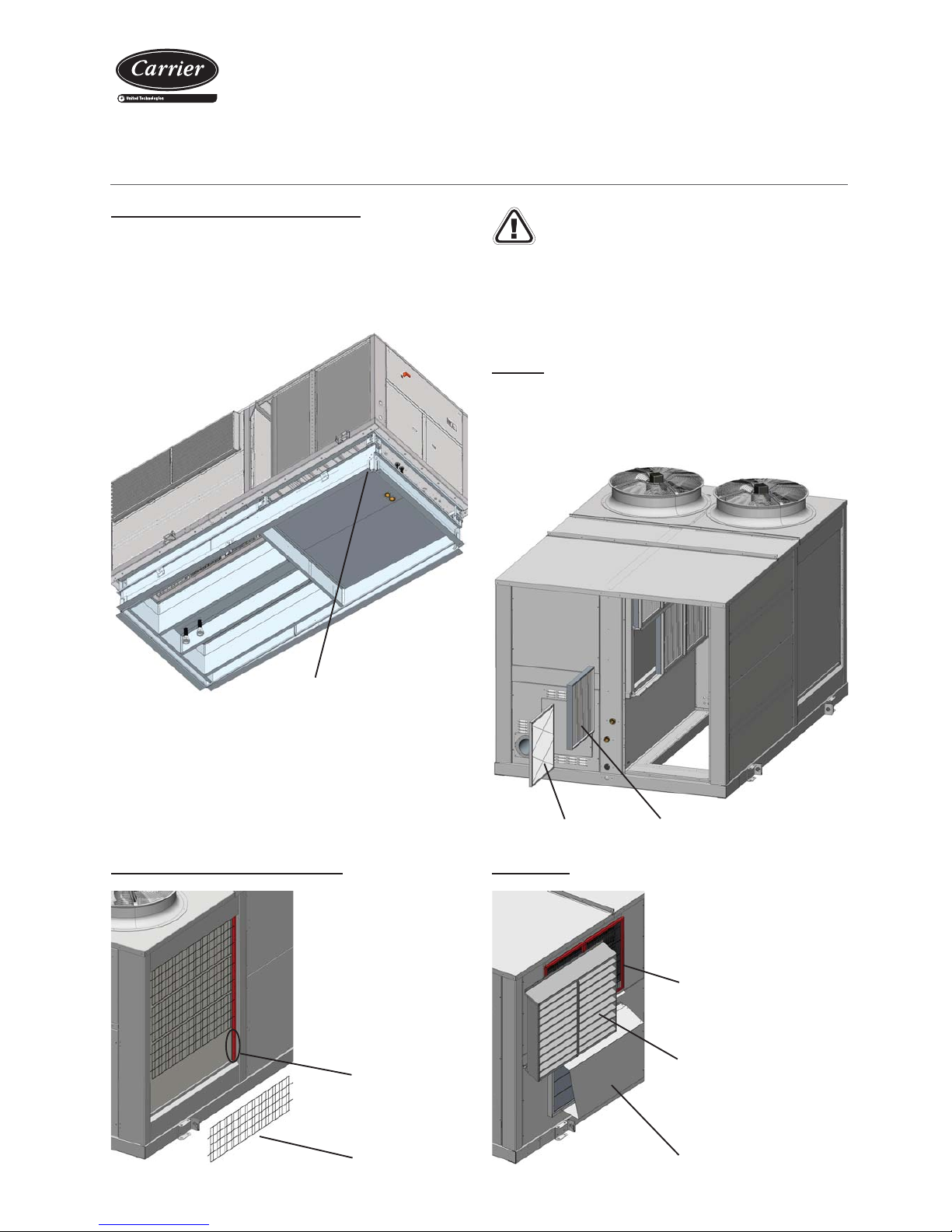
frames.
Outdoor coil protection grille
All the models can include a
protection grille for this coil.
This grille is fi xed by modules
in the holes made for this goal
in the unit's support.
11. OPTIONS
The installation of the following options causes pressure
drops at air level which means this has to be taken into
account in the selection of higher pressure fans (optional) or
in the substitution of the standard pulley set with a new set
that generates a higher turn speed to the pad. Both the fan
performance curves, as well as the pressure drop graphs
in the options, can be consulted in the technical brochure
for the 48EN/EH series.
Filters
Creased opacimetric fi lters
All model types can substitute the fi ltering mesh that the units include
regularly with G4 rating, mounted on the same frames. Also, creased
opacimetric F6 to F9 rating fi lters can be added.
Gravimetric fi lters
Stop-drop
The units with outdoor air intake can
include a stop-drop in this intake.
Stop-drop
Air outlet damper
Outdoor air damper
(displaced)
Grille module
Holes
Adjustment system
Page 19
Packaged rooftop units
with integrated gas burner
19
12. MAINTENANCE
V-220004
Caution: Before intervening in the unit, cut off main
power.
Recommendations:
In general, a corrosion control must be performed on the metallic parts
of the unit (frame, bodywork, exchangers, electric panel, etc.). All the
electric connection states must be checked as well, as well as the air
tightness of the different circuits.
Next, some recommendations are stated to perform the cleaning of
the unit's components:
Air coil
- Check that the coil is free from dust and grease.
- Cleaning the accumulated dust on the coil can be performed with
a vacuum cleaner perpendicular to the fi ns or with a low-pressure
water cleaner. Grease can be removed with water with degreaser.
Do not put stress on the fi ns as they could deform.
Condensates drain pan
- Check that the condensates pan is clean. There should be no
stagnant water.
- Check that the drain is not clogged.
- Cleaning of the pan can be done with water and non-abrasive
detergent.
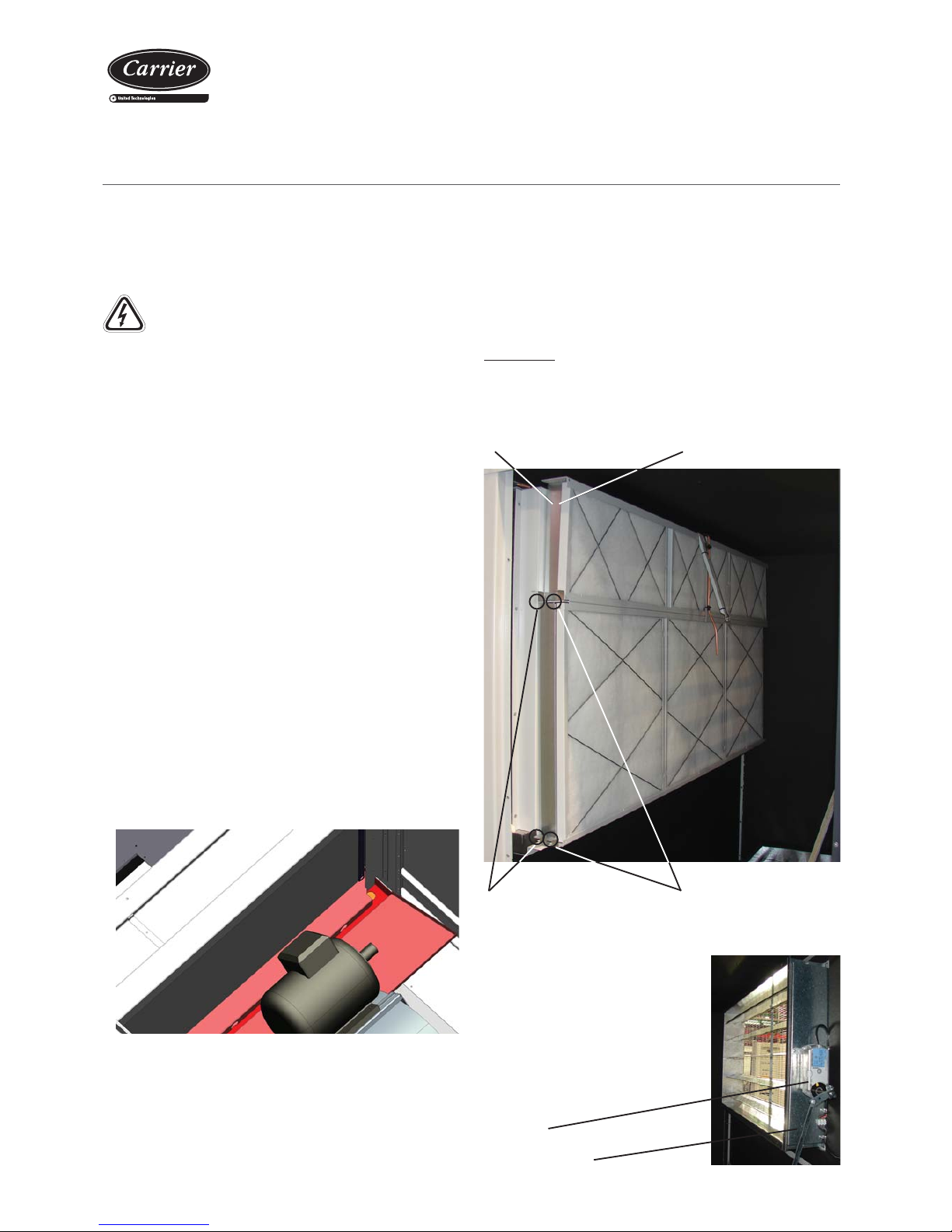
Gravimetric fi ltersOpacimetric fi lters
Tabs for displacement of the
opacimetric fi lters
Air fi lters
- Clean usually. Depending on the installation conditions, the fi lter
aspect must be examined to defi ne the cleaning periodicity.
- Gravimetric fi lters: Cleaning the fi ltering mesh can be done with a
household vacuum cleaner, or by submerging it in water.
- Creased opacimetric fi lters: these have to be replaced. Foresee
replacement.
Filter removal:
The frames with the gravimetric fi lters as well as opacimetric frames (if
the unit has includes them) are assembled over a sheet steel profi le.
Frames are moved by lifting the tab and dragging along the rail.
The minimal maintenance operations and their periodicity will be made
according to the national regulations.
Any intervention on the electric cooling components must be made by
a qualifi ed and authorized technician.
Centrifugal fan
- Verify that the turbine and the motor remain clean.
- Foresee having a spare belt set for the fans.
- The motors and the fans have bushings that have been lubricated and
sealed and, thus, do not need further lubrication.
Tabs for displacement of the
gravimetric fi lters
Mixing boxes and free-cooling
In units with mixing box assemblies with
motorised dampers (MS, MA and MC0
assemblies) it is advisable to check the
condition of the servomotor. In these
units the mixing damper is locked to
the outdoor air inlet.
Outdoor air damper
Servomotor
Page 20
Packaged rooftop units
with integrated gas burner
20
Refrigerant
Qualifi ed personnel must perform a periodic control to air tightness
depending on the refrigerant load, in accordance with the regulation
(CE) Nº 842/2006.
It is important not to ever forget that the cooling systems contain
liquids and vapours under pressure. The service pressure of R-410A is
approximately 1.5 times higher than that of R-407c.
- All necessary precautions must be taken during the partial opening
of the cooling circuit. This opening entails the discharge of a certain
amount of refrigerant to the atmosphere. It is essential to limit to its
minimum this amount of lost refrigerant by pumping and isolating the
load in some other part of the circuit.
- The refrigerant fl uid at low temperature can cause infl ammatory
injuries similar to burns when contacting the skin or eyes. Always
use protection glasses, gloves, etc. when opening ducts that may
contain liquids.
- The refrigerant in excess must be stored in appropriate containers
and the amount of refrigerant stored at the technical rooms must be
limited.
- Refrigerant barrels and deposits must be handled with precaution
and visible warning signs must be placed to attract attention over
the risks of intoxication, fi re and explosion linked to the refrigerant.
- At the end of its useful life, the refrigerant must be retrieved and
recycled as per the current regulations.
Gas Burner
Oil
- Check the oil level and aspect. In case of a colour change, check
the oil quality using a contamination test.
- In the case of the presence of acid, water or metallic particles, replace
the affected circuit oil, as well as the dehydrant fi lter.
- In the event of an oil charge change, only new oil will be used, which
will be identical to the original oil and taken from a can tightly closed
until the moment of the charge.
Note: Both the oil type as well as the volume needed for each model
are stated in the Technical characteristic tables in chapter 3.
Caution: Before starting any maintenance operations
ensure that the supply of gas and electricity have been
turned off.
V-220004
Only qualifi ed staff are allowed to undertake maintenance
tasks or resolve a breakdown.
Pay attention to the temperatures of some components after
operation. They could be very high (exchanger, chimney,
etc).
Hazard: Never use a naked fl ame whilst checking the burner.
Never store fl ammable material in the machine room.
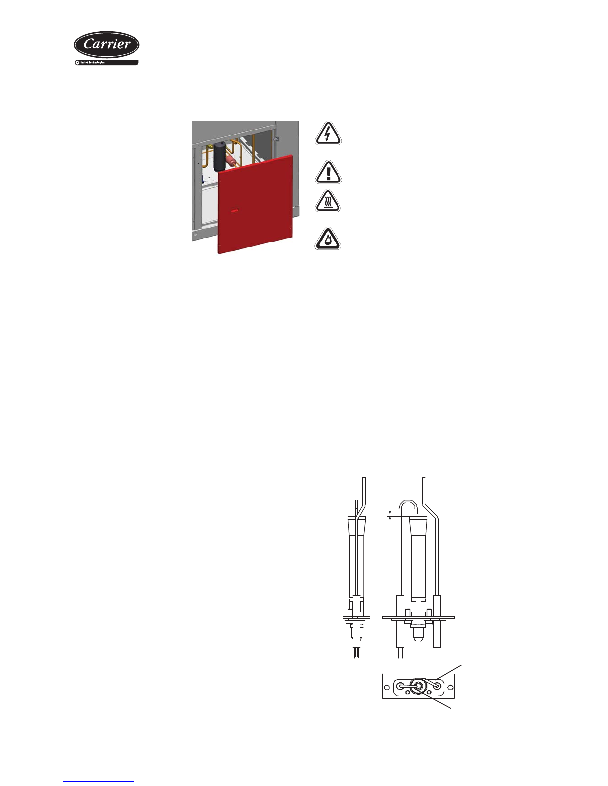
1. The ignition, fl ame detector and the electrodes
Disassemble the set and clean the steel grille and the nozzle with a
blast of compressed air. Check that the ceramic is intact and remove
any oxide residue from the metal parts of the electrodes using emery
paper. Check the correct positioning of the electrodes (see diagram
below). Check that the detection electrode is positioned tangently
to the head of the burner, not inside it. The ignition electrode must
rest on the ignition pilot grille.
Check that the ignition
electrode is working between
the grille and the outer edge
2/3mm
Keep the detection
electrode tangent to
the ignition pilot head
The maintenance and checking of the combustion must be performed
in compliance with the legislation in force. Any modifi cation or change
in the material must be undertaken with the manufacturer's consent;
the replacement of a faulty component for another non-compliant
component could present a hazard for which CARRIER could not
accept liability.
These burners operate with minimum maintenance, however in order
to guarantee optimum performance when starting each warming stage
check:
Dehydrant fi lter
- The filter function is the
preserve the cooling circuit
clean and without humidity,
neutralizing the acids that can
be found in the cooling circuit.
Verify dirt by measuring the
difference in temperature at
the tubing level between the
inlet and the outlet of the
dehydrator.
- If necessary, replace.
Page 21
Packaged rooftop units
with integrated gas burner
21
E
A
B
2. The smoke discharge ducts and the air inlet
Check the condition of the ducts by looking inside or using suitable
tools. Remove the dust from the air inlet terminal.
3. The venturi
If required, use a brush to remove the dust from the venturi inlet
ensuring that it does not fall inside.
4. Cleaning the exchanger
Optimised combustion in these burners prevents the appearance of
residual products. Nevertheless, dirt could be deposited inside the
exchanger pipes due to the fi ne dust pulled through the combustion
air duct.
Since it is not possible to plan a precise schedule for cleaning the
exchanger a considerable reduction in the gas fl ow rate could indicate
that there is dirt inside.
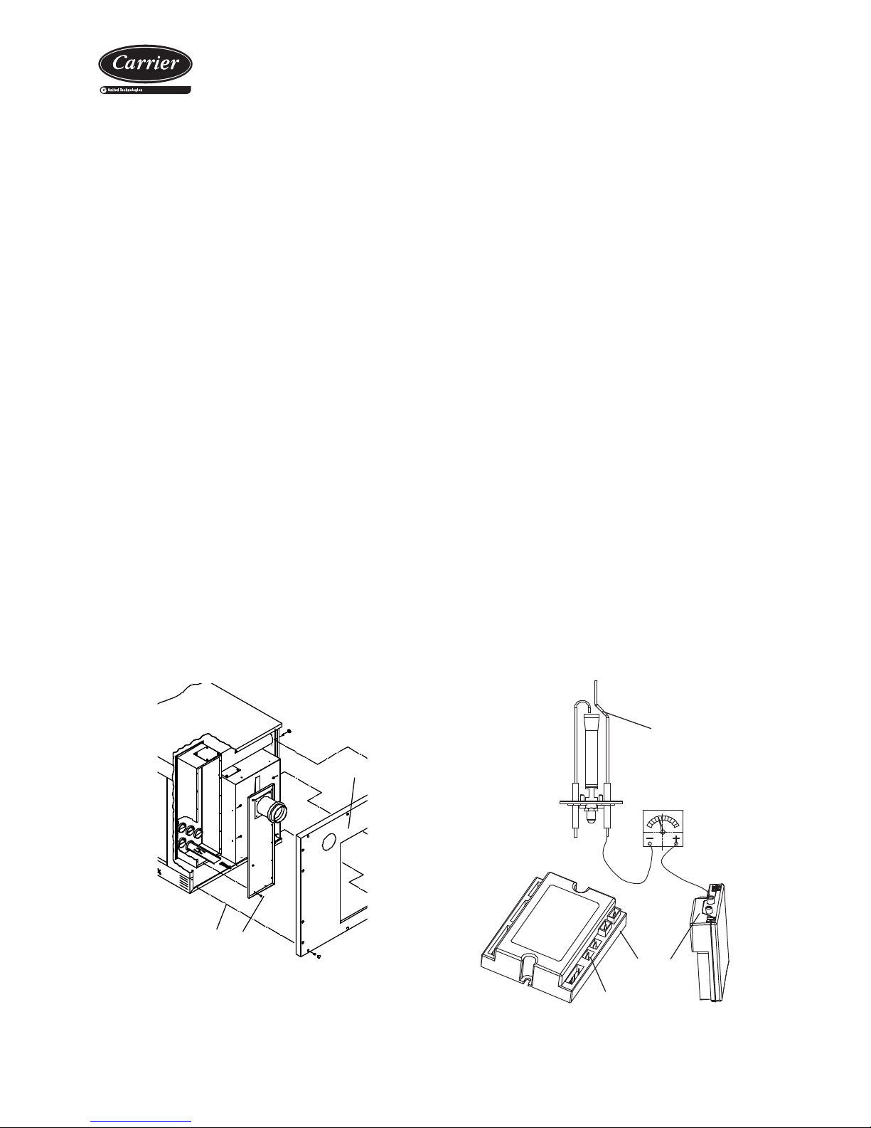
If the exchanger has to be cleaned observe the following operation
when the unit is cold and disconnected from the supply:
• Remove the door and the gasket which goes around the edge of
the control plate carefully to avoid damaging it.
• Remove self-tapping screws (A) which hold the control plate and
the outer panel (B).
• Disconnect the gas pipe, the electric power supply and the smoke
discharge system.
• Remove the outer panel (B).
• Remove screws (E) which hold the smoke manifold lid.
• Use a suitable brush to clean the entire length of the pipes pushing
all the dirt towards the outlet to collect it.
• Check that the condensate discharge gasket is clean.
• Reassemble all the parts ensuring that the sealing is hermetic.
7. The operation of the fl ame control device
With the burner in operation, close the gas valve and check that it
blocks and that the remote control displays the error F1 on the screen
(consult the section on “Burner Safety Devices”). Open the valve,
unblock the control and check that the burner is operating correctly.
8. The safety thermostat and the air differential pressostat
With the burner in operation open the thermostat using a suitable tool
(230V). Quickly disconnect the pressostat or the safety thermostat
and wait until the remote control displays the error F2 on the screen.
Connect the thermostat again and unblock.
9. Ionisation current
Perform this operation using a device which is able to measure a direct
current in microamperes. Do the following:
• Disconnect the unit from the electric power supply.
• Disconnect the cable from the fl ame control device and connect
it to the negative pole of the ammeter.
• Use a cable to connect the positive pole of the ammeter and the
fl ame control device.
• Switch on the device and wait until the burner starts.
• Measure the ionisation current.
This value must not be less than 2A. Lower values would indicate
that the detection electrode is diverted, rusty or about to break.
6. The inlet pressure of the gas valve
Check that the valve inlet pressure corresponds to that required for
the gas. This check must be carried out with the burner operating
at maximum output.
Replace the gas valve if required. Refer to the manufacturer's
brochure.
5. Cleaning the condensates drain siphon (if there is one)
Clean the siphon every year and check the gaskets. Ensure that there
are no metal residues. If there are clean the siphon more frequently.
After emptying the siphon, fi ll it with water and close it using a suitable
lid before restarting the burner.
Microammeter DC
Detection
electrode
Flame
control device
mod. 032/092
mod. 150/200
Flame detection
Note: The aforementioned items from 1 to 4 must be performed with
the electric power supply and the gas supply disconnected. Items 5 to
9 must be verifi ed with the burner in operation.
Page 22

Packaged rooftop units
with integrated gas burner
22
13. CONTROL AND ANALYSIS OF BREAKDOWNS
Symptom Cause Solution
Evaporation pressure very high in relation with
the air inlet
a) Load excess
b) High air temperature
c) Compressor suction not air tight
d) Cycle reversing valve in middle position
a) Collect refrigerant
b) Verify overheating
c) Verify compressor state and replace
d) Check that the valve is not clogged. Replace if
necessary
Very low condensation pressure a) Gas lack
b) Compressor suction not air tight
c) Cycle inversion valve in middle position
d) Liquid circuit plugging
a) Search for leaks, complete charge
b) Verify compressor state and replace
c) Check that the valve is not clogged. Replace if
necessary
d) Verify the dehydrating fi lter and expansion valve
Condensation pressure very high in relation to the
air outlet, high pressostat cutoff
a) Insuffi cient air fl ow
b) Air inlet temperature very high
c) Dirty condenser (does not exchange)
d) Much refrigerant load (fl ooded condenser)
e) The condenser fan is broken down
f) Air in the cooling circuit
a) Verify the air circuits (fl ow, fi lter cleanliness...)
b) Verify the control thermostat readjustment
c) Clean it
d) Collect refrigerant
e) Repair
f) Make vacuum and load
Evaporation pressure too low (low pressostat
cutoff)
a) Low fl ow in evaporator. Air recirculation
b) Frozen evaporator
c) Liquid line as different temperatures at fi lter inlet
and outlet
d) Gas lack
e) Very low condensation pressure
f) Evaporator fan broken down
a) Verify the air circuits (fl ow, fi lter cleanliness...)
b) Verify defrost
c) Replace fi lter
d) Search for leaks, complete load
e) Temperature of air or water in condenser very low
(air or water fl ow very high), adjust fl ow
f) Repair
Compressor does not start, does not make noise
(humming)
a) No power
b) The contacts of a control element are open
c) Timing of anti cycle short does not allow the starting
d) Open contact
e) Contactor coil burnt
f) Indoor Klixon open
a) Check differential, fuses
b) Verify the safety chain of the electronic control
c) Verify electronic control
d) Replace
e) Replace
f) Wait for reactivation, verify intensity absorbed
Compressor does not start, motor sounds
intermittently
a) Electrical power supply very low
b) Power cable disconnected
a) Control line voltage and locate voltage drop
b) Verify connections
Repeated compressor starts and stops a) Because of high pressure
b) Control differential too short (short cycle)
c) Gas lack, cutoff because of low pressure
d) Dirty or frosted evaporator
e) The evaporator fan does not work, cuts off the low
pressostat
f) Expansion valve damaged or clogged by impurities
(cuts off low pressostat)
g) Dehydrating fi lter clogged (cuts off low safety)
a) Verify load
b) Increase differential
c) Search for leak, reload unit
d) Clean, verify evaporator air circuit
e) Replace or repair
f) Replace, as well as fi lter
g) Replace
The compressor makes a noise a) Loose attachment
b) Oil lack
c) Compressor noise
a) Fix
b) Add oil to recommended level
c) Replace
Noisy operation a) Unit installed without antivibration protection a) Place base over shock absorbers
Cycle reversing is not carried out:
- No defrosting
- Does not change winter - summer cycles
a) Electrical fault
b) Inversion valve coil defective
c) Defrost method not working
d) Cycle inversion valve in middle position
e) Control fault
a) Locate and repair
b) Replace
c) Verify parameters
d) T ap with running compressor Replace if necessary
e) Locate and repair
Page 23

Page 24

Order No.: 10051, 03.2015. Supersedes order No.: New Manufactured for CARRIER in Spain.
The manufacturer reserves the right to change the specifi cation without prior notice. Printed in the European Union.
 Loading...