

Page 1
Installation Instructions
Part Numbers: CRLOWAMB033A00 THROUGH CRLOWAMB038A00
CONTENTS
Page
SAFETY CONSIDERATIONS . . . . . . . . . . . . . . . . . . . . . . 1
GENERAL . . . . . . . . . . . . . . . . . . . . . . . . . . . . . . . . . . . . . . 1-3
INSTALLATION . . . . . . . . . . . . . . . . . . . . . . . . . . . . . . . . 3-12
Pre-Installation . . . . . . . . . . . . . . . . . . . . . . . . . . . . . . . . . . . 3
Step 1 — Install Field-Fabricated Wind Baffles . . . 3
Step 2 — Mounting and Electrical Connections
for Motormaster
Step 3 — Configure Motormaster V Control . . . . . 11
Step 4 — Test Motormaster V Control . . . . . . . . . . . 11
START-UP . . . . . . . . . . . . . . . . . . . . . . . . . . . . . . . . . . . . 11-13
TROUBLESHOOTING. . . . . . . . . . . . . . . . . . . . . . . . . 13-15
SAFETY CONSIDERATIONS
Installation, start-up, and servicing of this equipment can be
hazardous due to system pressures, electrical components, and
equipment location (roofs, elevated structures, etc.).
Only trained, qualified installers and service technicians
should install, start up, and service this equipment.
When working on this equipment, observe precautions in
the literature and on tags, stickers, and labels attached to the
equipment and any other safety precautions that may apply.
®
V Control . . . . . . . . . . . . . . . . . . . . 5
48/50P2,P3,P4,P5030-100
Low Ambient Operation
MOTORMASTER® V Control Accessory
50/60 Hz
WARNING
Open all remote disconnects before servicing this equipment. Electrical shock could result in personal injury.
GENERAL
This book contains instructions for the installation, start-up,
and service of the Motormaster V (MMV) control on
48/50P030-100 units.
The Motormaster V control is a motor speed control device
which adjusts condenser fan motor speed in response to varying
liquid refrigerant pressure. A properly applied Motormaster V
control extends the operating range of air-conditioning systems
and permits operation at lower outdoor ambient temperatures.
To operate these units at very low ambient temperatures, Motormaster V controls (Fig. 1) must be added. Field-fabricated and
installed wind baffles are also required for units in areas with prevailing winds of more than 5 mph (8 kph) and where temperatures drop below 32 F (0° C). The Motormaster V control permits
operation of the unit to an ambient temperature of –20 F (–29 C).
The control regulates the speed of one or two 3-phase fan motors
depending on unit size. Replacement of the fan motor on most
units is not necessary since the control is compatible with the
factory-installed fan motors. To verify that unit fan motors are
compatible with the control see Table 1.
See Tables 2-4 for the Motormaster V control accessory package usage and contents. Field wiring of control is required.
Table 1 — Replacement Motor Part Numbers
48/50P2,P3,P4,P5 UNIT SIZE VOLTAGE ACCESSORY PART NUMBER
208/230-3-60 Not Required, Std Unit Motor
035
030, 040-060
070
075-100
Manufacturer reserves the right to discontinue, or change at any time, specifications or designs without notice and without incurring obligations.
Catalog No. 04-53480070-01 Printed in U.S.A. Form 48/50P-2SI Pg 1 9-09 Replaces: New
400-3-50, 460-3-60 Not Required, Std Unit Motor
575-3-60 Not Required, Std Unit Motor
380-3-60 HD56AK380
208/230-3-60 HD52AK002
400-3-50, 460-3-60 HD52AK002
575-3-60 Not Required, Std Unit Motor
380-3-60 Not Required, Std Unit Motor
208/230-3-60 HD52AK002 (2 Required)
400-3-50, 460-3-60 HD52AK002 (2 Required)
575-3-60 Not Required, Std Unit Motor
380-3-60 Not Required, Std Unit Motor
208/230-3-60 Not Available
400-3-50, 460-3-60 HD52AK002 (2 Required)
575-3-60 Not Required, Std Unit Motor
380-3-60 Not Available
Page 2
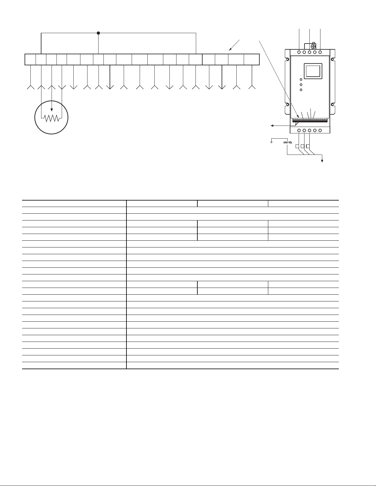
Table 2 — Motormaster® V Control Package Contents — 48/50P030-060 Units
256
2
12 13A
13B
13C
1
2
3
TO MOTOR(S)
BLK
YEL
BLU
FROM FUSE BLOCK
B
TO PRESSURE
TRANSDUCER
12561
12
2 14 13A 13B 13C 15 25 2 30 31 TXA
TXB
COM
+5V
TERMINAL
BLOCK
L1
L2
L3
T1
T2
T3
B-
B+
PRESSURE
TRANSDUCER
Fig. 1 — Motormaster® V Control
NOTE: Wire colors for MMPT:
2 — BLACK (A)
5 — GREEN (C)
6 — RED (B)
ITEM CRLOWAMB033A00 CRLOWAMB034A00 CRLOWAMB035A00
Connector (
Connector (1-in.) HW60HH006
Controller, 230 V 2 Hp HR46TN001 — —
Controller, 460 V 2 Hp — HR46TN002 —
Controller, 575 V 2 Hp — — HR46TN003
Enclosure 30RA500381
Enclosure Cover 30RA500519
Enclosure Mounting Bracket 50EJ500656
Fan Relay HN61KK055
Relay Base HN79KK035
Fuse Block HY11UT035
Fuse 15A, KTK-R, Class CC — HY10KB151 (3) HY10KB151 (3)
Fuse 20A, KTK-R, Class CC HY10KB200 (3) — —
Harness Assembly 48ZZ401971
Harness Assembly 48EJ402454
Harness Assembly 48ZZ402001
Label 48ZZ502002
Transducer HK05ZZ001
Transducer Harness 48EJ403240
Varnish Cloth (Large) 48DA510141
Varnish Cloth (Small) 38C24601
Wire Tie HY76TB123 (12)
Wire Tie HY76TB045 (5)
Wire, 16 Gage 72 in. Long WHT (1), GRY (1)
1
/2-in.) HW60EA001
2
Page 3
Table 3 — Motormaster V Control Package Contents — 48/50P070-100 Units
ITEM CRLOWAMB036A00 CRLOWAMB037A00 CRLOWAMB038A00
1
Connector (
Connector (1-in.) HW60HH006 (2)
Controller, 230 V 2 Hp HR46TN001 (2) — —
Controller, 460 V 2 Hp — HR46TN002 (2) —
Controller, 575 V 2 Hp — — HR46TN003 (2)
Enclosure 30RA500381 (2)
Enclosure Cover 30RA500519 (2)
Enclosure Mounting Bracket 50EJ500656 (2)
Fan Relay HN61KK055 (2)
Relay Base HN79KK035 (2)
Fuse Block HY11UT035 (2)
Fuse 15A, KTK-R, Class CC — HY10KB151 (6) HY10KB151 (6)
Fuse 20A, KTK-R, Class CC HY10KB200 (6) — —
Harness Assembly 48ZZ401971 (2)
Harness Assembly 48EJ402454 (2)
Harness Assembly 48ZZ402001 (2)
Label 48ZZ502002
Transducer HK05ZZ001 (2)
Transducer Harness 48EJ403240 (2)
Varnish Cloth (Large) 48DA510141 (2)
Varnish Cloth (Small) 38C24601 (2)
Wire Tie HY76TB123 (6)
Wire Tie HY76TB045 (2)
Wire, 16 Gage 72 in. Long WHT (2), GRY (2)
/2-in.) HW60EA001 (2)
Table 4 — Motormaster V Control Package Usage
UNIT VOLTAGE ITEM DESCRIPTION
48/50P030-060
48/50P070-100
INSTALLATION
Pre-Installation —
package before installing. File a claim with the shipper if there
is shipping damage or if a part is missing.
Inspect the contents of this accessory
Step 1 — Install Field-Fabricated Wind Baffles
WARNING
To avoid the possibility of electrical shock, open all disconnects before installing or servicing this accessory.
On size 040-060 units, in areas with prevailing winds of
more than 5 mph (8 kph) and where temperatures drop below
32 F (0° C), wind baffles must be field fabricated to ensure
208/230 CRLOWAMB033A00
380, 400, 460 CRLOWAMB034A00
575 CRLOWAMB035A00
208/230 CRLOWAMB036A00
380, 400, 460 CRLOWAMB037A00
575 CRLOWAMB038A00
proper cooling cycle operation at low-ambient temperatures
with Motormaster V controls. Wind baffles are not needed on
size 030, 035, and 070-100 units. See Fig. 2 for baffle details.
Use 20-gage (1 mm) galvanized sheet metal, or similar corrosion-resistant material for the baffles. Use field-supplied screws
to attach baffles to unit. Screws should be
eter or larger. Screws should not be more than
1
/4-in. (6.3 mm) diam-
1
/2-inch in length.
Drill required screw holes for mounting baffles.
CAUTION
To avoid damage to refrigerant coils, electrical components, and wiring use extreme care when drilling screw
holes and screwing in fasteners.
3
Page 4
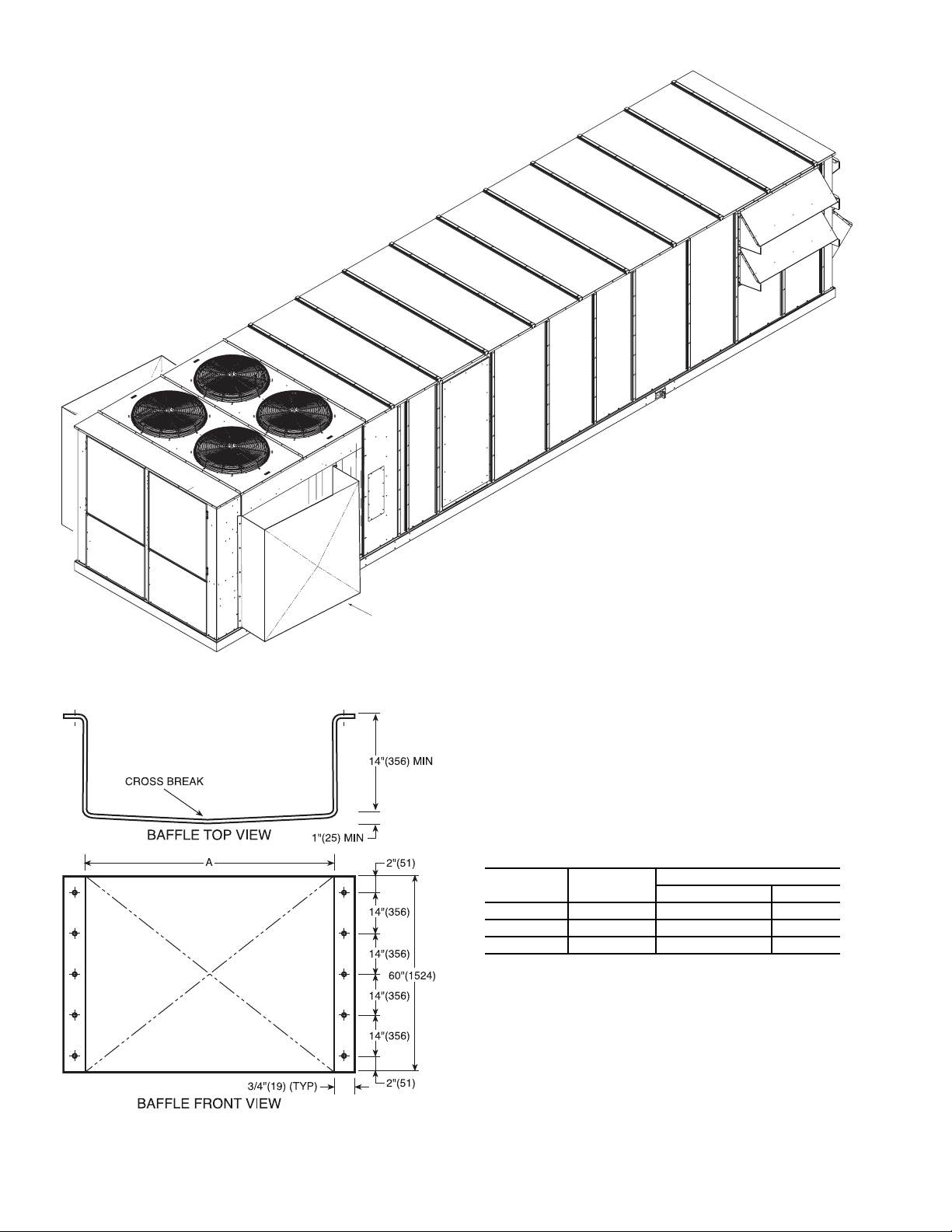
WIND BAFFLE
Fig. 2 — Wind Baffle Details
NOTE: 48/50P030, 035, and 070-100 units do not require
baffles.
UNIT SIZE QUANTITY
DIMENSION “A”
in. mm
030,035 Not Used — —
040-060 2 78.125 ± 0.125 1984 ± 3
070-100 Not Used — —
BAFFLE INSTALLATION LOCATION (SIZES 050 AND 060 SHOWN)
a48-8561
a48-8560
4
Page 5
Step 2 — Mounting and Electrical Connections for Motormaster® V Control
WARNING
To avoid possibility of electric shock and personal
injury, open and tag all electrical disconnects before
installing or servicing unit.
WARNING
Hazard of electric shock. Wait three minutes after disconnecting incoming power before servicing drive. Capacitors
retain charge after power is removed.
CAUTION
To avoid damage to the small terminals on the Motormaster V control, use care when tightening the compression
terminals and use the proper size screwdriver.
CAUTION
DO NOT connect incoming AC power to Motormaster V
output terminals T1, T2, and T3. Severe damage to the control will result.
48/50P030-060 UNITS — For 48/50P030-035 units, the Motormaster controlled outdoor-fan motor (OFM) is the no. 1
OFM (see Fig. 3). The no. 2 OFM is controlled by the Com-
fortlink head pressure control routine.
For 48/50P040 units, the Motormaster controlled outdoorfan motor (OFM) is the no. 3 OFM (see Fig. 3). The no. 1 and 2
OFMs are controlled by the Comfortlink head pressure control
routine.
For 48/50P050-060 units, the Motormaster controlled outdoor-fan motor (OFM) is the no. 1 OFM (see Fig. 3). The no. 2,
3, and 4 OFMs are controlled by the Comfortlink head pressure
control routine.
Use the following procedure to mount and connect the
MMV controllers to these units:
1. Disconnect power to the unit. Lockout and tag power disconnect.
2. Remove control box covers.
3. For size 030-035 units, remove panel from condenser
section on OFM 1 side of the unit in order to gain access
to the outdoor fan section. See Fig. 4. For size 040-060
units, remove panel above control box as shown in Fig. 5
and 6.
4. Mount accessory fuse block HY11UT035 and fan relay
base HN79KK035 inside control box as shown in Fig. 7.
Secure components with ½-in. sheet metal screws.
a. Insert fuses into fuse blocks and relays into relay
bases.
b. Install harness 48EJ402454 from load side of CCB
(control circuit breaker terminals 21, 22, 23) to line
side of MMF (Motormaster V fuse block) as
shown in Fig. 8. Note that it may be easier to pick
up the load side of CCB from the ¼-in. male quick
connect terminals on the line side (terminals 11,
12, 13) of the OFC contactors (see power schematic on control box door).
c. Connect FR (fan relay) coil to OFC1 coil using the
72-in. long 16 gage white and gray wires (stripped
end goes to FR) as shown in Fig. 8.
5. Mount the MMV controller enclosure 30RA500381 on
the bulkhead of the unit inside the outdoor fan section, as
shown in Fig. 4-6, using the mounting brackets
50EJ500656 installed on the enclosure. Remove the enclosure cover and install the ½-in. HW60EA001 and 1-in.
HW60HH006 connectors in the holes in the lower right
hand side of the enclosure.
6. Connect transducer HK05ZZ001 to the liquid line service
Schrader port of refrigerant Circuit A. Plug transducer cable 48EJ403240 into transducer. Run cable to the MMV
enclosure, as shown in Fig. 4-6.
Run MMPT (Motormaster V pressure transducer) cable
through ½-in. connector of MMV enclosure (do not tighten connector screws at this time). Connect red, green, and
black wires to MMV terminals 6, 5, and 2 as shown in
Fig. 8. Terminate drain wire of transducer cables under
one of the lower MMV mounting screws.
7. Make remaining electrical connections to MMV (see
Fig. 8).
a. In main control box, disconnect black, red, blue,
and green wires from load side (terminals 21, 22,
23) of OFC1 (sizes 030-035, 050-060) contactor or
OFC 3 (size 040) (label cable from OFC1 or OFC3
(size 040) as OFM1 or OFM3 (size 040). Pull
wires out through the hole in the bottom of the
control box and run them up the corner post to the
opening of the cable tray on the side of the control
box, as shown in Fig. 4-6. Run the cable through
the wire tray to the MMV enclosures.
b. Run the OFM1/OFC3 (040) cable through the 1-in.
connector of the MMV enclosure (do not tighten
connector screws at this time). Remove ring terminals from black, red, and blue wires and strip insulation back 3/8-in. Connect black, red, and blue
wires to MMV terminals T1, T2, and T3. Connect
green ground wire to MMV ground screw.
c. In the main control box connect Motormaster VFD
(variable frequency drive) harness 48ZZ401971 to
the load side of the MMF (label the opposite end of
this harness as MMF). Run the harness along the
bottom of the control box and out through the hole
that the OFM harness was in. Pull the harness out
through the hole in the bottom of the control box
and run it through the opening of the cable tray (in
the same manner as the OFM harnesses).
d. Run the MMF cable through 1-in. connector of the
MMV enclosure (do not tighten connector screws
at this time). Connect L1, L2, and L3 wires to
MMV terminals L1, L2, and L3. Connect green
ground wire to MMV ground screw. Place 1 large
varnish cloth 48DA510141 around both cables at
the point they enter the 1-in. connector. Tighten
down connector screws being careful not to damage the cables.
e. In the main control box connect one Motormaster
VFD harness 48ZZ402001 to the NO (normally
open) contact of the FR (see Fig. 8). Run the harnesses along the bottom of the control box and out
through the hole that the OFM harness was in. Pull
the harness out through the hole in the bottom of
the control box and run it through the opening of
the cable (in the same manner as the OFM
harness).
5
Page 6

UNIT
48/50P
FAN ARRANGEMENT FAN NO. NORMAL CONTROL
030,035
1
MMV-A
2
Controlled by the ComfortLink™ head pressure
control routine
040
1
Controlled by the ComfortLink head pressure
control routine
2
3
MMV-A
050-060
1 MMV-A
2 Controlled by the ComfortLink head pressure
control routine
3
4
070,075
1
MMV-B
2
Controlled by the ComfortLink head pressure
control routine
3
MMV-A
4
Controlled by the ComfortLink head pressure
control routine
090,100
1
Controlled by the ComfortLink head pressure
control routine
2
MMV-B
3
Controlled by the ComfortLink head pressure
control routine
4
5
6
MMV-A
Control Box
1
2
Control Box
1
23
24
Control Box
1
24
6
53
Fig. 3 — Fan Control
REMOVE PANEL
RUN ELECTRICAL HARNESSES UP THE SIDE
OF THE UNIT IN THE SPACE BETWEEN THE
CORNER POST AND THE CONTROL BOX.
ROUTE THE WIRING INTO THE WIRE TRAY,
THEN RUN APPROPRIATE WIRES TO OFM 1
AND MOTORMASTER CONTROL
MOTORMASTER
CONTROL
TRANSDUCER
HARNESS FROM
CIRCUIT A LIQUID LINE
TRANSDUCER TO MMV
Fig. 4 — MMV Control Mounting — 48/50P030,035 Units
a48-8562
Control Box
1
3
4
2
Control Box
1
3
6
Page 7

REMOVE PANEL
RUN ELECTRICAL HARNESSES UP THE SIDE
OF THE UNIT IN THE SPACE BETWEEN THE
CORNER POST AND THE CONTROL BOX, THEN
ALONGSIDE THE WIRE TRAY. ROUTE
APPROPRIATE WIRES TO MOTORMASTER AND
OFM 3
MOTORMASTER
CONTROL
RUN TRANSDUCER HARNESS FROM CIRCUIT A
TRANSDUCER TO MOTORMASTER ALONG THE LENGTH OF
THE BOTTOM OF THE CONDENSER COIL THEN UP INTO
MOTORMASTER. RUN THE WIRES ALONG THE OUTSIDE
OF THE COIL TRAY.
Fig. 5 — MMV Control Mounting — 48/50P040 Units
a48-8563
RUN ELECTRICAL HARNESSES UP THE SIDE OF THE
MOTORMASTER
CONTROL
Fig. 6 — MMV Control Mounting — 48/50P050-060 Units
a48-8564
UNIT IN THE SPACE BETWEEN THE CORNER POST
AND THE CONTROL BOX, THEN ALONGSIDE THE WIRE
TRAY. ROUTE APPROPRIATE WIRES TO
MOTORMASTER AND OFM 1
RUN TRANSDUCER HARNESS FROM CIRCUIT A
TRANSDUCER TO MOTORMASTER ALONG THE
LENGTH OF THE BOTTOM OF THE CONDENSER COIL
THEN UP INTO MOTORMASTER. RUN THE WIRES
ALONG THE OUTSIDE OF THE COIL TRAY.
REMOVE PANEL
7
Page 8

MMF-A MMF-B FR-A FR-B
Fig. 7 — 48/50P Control Box Details
LEGEND
FR — Fan Relay
MMF — Motormaster V Fuse Block
a48-8565
OFM-1 (030,035,050-060)
OFM-3 (040)
MMV-A
L1
L2
L3
T1
T2
T3
B-
B+
BLK
BLK
BLU
YEL
1
2
5
6
11
12
2
14
13A
13B
13C 15
5
9
MMPT
230-3-60 SHOWN.
REFER TO TABLE 4 FOR
ALTERNATE VOLTAGE
CONNECTIONS
FR-A
OFC1
13
14
C1
C2
ADD FAN RELAY (FR)
IN PARALLEL WITH OFC1
CCB
MM-F
BLU
YEL
A
B
C
TB
BLU
RED
BLK
GRN/YEL, DRAIN
RED
BLK
BLU
RED
BLK
GRY
WHT
11 12
13
22
2321
FR-A
Fig. 8 — Motormaster® V Accessory Wiring — 48/50P030-060 Units
LEGEND
CCB — Control Circuit Breaker
FR — Fan Relay
MM-F — Motormaster V Fuse Block
MMPT — Motormaster Pressure Transducer
MMV — Motormaster V Control
OFC — Outdoor-Fan Contactor
OFM — Outdoor-Fan Motor
TB — Terminal Block
NOTE: Wire colors for MMPT:
2 — BLACK (A)
5 — GREEN (C)
6 — RED (B)
a48-8566
8
Page 9

f. Run the FR cable through the
1
/2-in. connector of
the MMV enclosure (do not tighten connector
screws at this time). Connect black wire to MMV
terminal 2 and red wire to MMV terminal 1, 13A,
or 13C (see Table 4). Place 1 small varnish cloth
38C24601 around both cables at the point they
enter the
1
/2-in. connector. Tighten down connector
screws being careful not to damage the cables.
8. Bundle excess wire and dress harnesses with wire ties.
9. Re-attach control box, MMV enclosure, and cable tray
covers.
48/50P070-100 UNITS — For 48/50P070-075 units, two
Motormaster controls are used to control two independent outdoor-fan motors (OFM). The refrigerant circuit-A Motormas-
®
ter
controlled OFM is the no. 3 OFM. The refrigerant circuitB Motormaster controlled OFM is the no. 1 OFM (see Fig. 3).
The no. 2 and 4 OFMs are controlled by the ComfortLink™
head pressure control routine.
For 48/50P090-100 units, the two Motormaster controls are
used to control two independent outdoor-fan motors. The refrigerant circuit-A Motormaster controlled OFM is the no. 6
OFM. The refrigerant circuit-B Motormaster controlled OFM
is the no. 2 OFM (see Fig. 3). The no. 1, 3, 4, and 5 OFMs are
controlled by the ComfortLink head pressure control routine.
Use the following procedure to mount and connect the
MMV controllers to this unit:
1. Disconnect power to the unit. Lockout and tag power disconnect.
2. Remove control box covers.
3. Remove fan decks to gain access to each circuit’s respective Motormaster controlled OFM, as shown in Fig. 9 and
10.
4. Mount accessory fuse blocks HY11UT035 (label 1 as
MMF-A and the other as MMF-B) and fan relay bases
HN79KK035 (label 1 as FR-A and the other as FR-B) inside control box as shown in Fig. 7. Secure components
with ½-in. sheet metal screws.
a. Insert fuses into fuse blocks and relays into relay
bases.
b. Install harnesses 48EJ402454 from load side of
CCB (control circuit breaker terminals 21, 22, 23)
to line side of MMF-A and MMF-B fuse blocks as
shown in Fig. 11. Note that it may be easier to
pickup the load side of CCB from the ¼-in. male
quick connect terminals on the line side (terminals
11, 12, 13) of the OFC contactors (see power schematic on control box door).
c. For 070 and 075 units:
Connect FR-A coil to OFC3 coil and FR-B coil to
OFC1 coil using the 72 in. long 16 gage white and
gray wires (stripped end goes to FR) as shown in
Fig. 11.
For 090 and 100 units:
Connect FR-A coil to OFC3 coil and FR-B coil to
OFC2 coil using the 72 in. long 16 gage white and
gray wires (stripped end goes to FR) as shown in
Fig. 11.
5. Mount the MMV controller enclosures 30RA500381on
the bulkhead, as shown in Fig. 9 (sizes 070 and 075) and
Fig. 10. (sizes 090 and 100) using the mounting brackets
50EJ500656 installed on the enclosures (label 1 as MMVA and the other as MMV-B). Remove the enclosure covers and install the ½-in. HW60EA001 and 1-in.
HW60HH006 connectors in the holes in the lower right
hand side of the enclosures.
6. Connect transducers HK05ZZ001 to the liquid line service Schrader ports, located under the V-coils of the condenser fan sections, of refrigerant circuit A and B. Circuit
A is the one closest to the Indoor Fan Motor section, and
circuit B is the one closest to the control box, (label circuit A transducer as MMPT-A and circuit B transducer as
MMPT-B).
7. Plug transducer cables 48EJ403240 into transducers (label stripped end of circuit A cable as MMPT-A and the
stripped end of circuit B cable as MMPT-B). Run cables
along inside of unit base rail and up the corner post to the
MMV enclosures, as shown in Fig. 9 and 10.
8. Run MMPT-A cable through
A enclosure, and MMPT-B cable through
1
/2-in. connector of MMV-
1
/2-in. connector of MMV-B enclosure (do not tighten connector
screws at this time). Connect red, green, and black wires
to MMV-A and MMV-B terminals 6, 5, and 2 as shown
in Fig. 11. Terminate drain wire of transducer cables under one of the lower MMV mounting screws.
9. Make remaining electrical connections to MMV-A and
MMV-B (see Fig. 11).
a. For 070 and 075 units:
In the main control box, disconnect black, red,
blue, and green wires from load side (terminals 21,
22, 23) of OFC1 and OFC3 contactors (label cable
from OFC1 as OFM1 and cable from OFC3 as
OFM3). Pull wires out through the hole in the bottom of the control box and run them up the corner
post to the opening of the cable tray on the side of
the control box, as shown in Fig. 9. Run the cable
through the wire tray to the MMV enclosures.
Run the OFM1 cable through the 1-in. connector
of the MMV-B enclosure (do not tighten connector
screws at this time). Remove ring terminals from
black, red, and blue wires and strip insulation back
3/8-in. Connect black, red, and blue wires to
MMV-B terminals T1, T2, and T3. Connect green
ground wire to MMV-B ground screw.
Run OFM3 cable through 1-in. connector of
MMV-A enclosure (do not tighten connector
screws at this time). Remove ring terminals from
black, red, and blue wires and strip insulation back
3
/8-inch. Connect black, red, and blue wires to
MMV-A terminals T1, T2, and T3. Connect green
ground wire to MMV-B ground screw.
For 090 and 100 units:
In Main Control box, disconnect black, red, blue,
and green wires from load side (terminals 21, 22,
23) of OFC2 and OFC3 contactors (label cable
from OFC2 as OFM2 and cable from OFC3 as
OFM3). Pull wires out through the hole in the bottom of the control box and run them up the corner
post to the opening of the cable tray on the side of
the control box, as shown in Fig. 10. Run the cable
through the wire tray to the MMV enclosures.
Run the OFM2 cable through the 1-in. connector
of the MMV-B enclosure (do not tighten connector
screws at this time). Remove ring terminals from
black, red, and blue wires and strip insulation back
3
/8-in. Connect black, red, and blue wires to MMVB terminals T1, T2, and T3. Connect green ground
wire to MMV-B ground screw.
Run OFM6 cable through 1-in. connector of
MMV-A enclosure (do not tighten connector
screws at this time). Remove ring terminals from
black, red, and blue wires and strip insulation back
3/8-in. Connect black, red, and blue wires to
MMV-A terminals T1, T2, and T3. Connect green
ground wire to MMV-B ground screw.
9
Page 10

b. In main control box connect one Motormaster
Fig. 9 — MMV Control Mounting — 48/50P070,075 Units
a48-8567
VFD harness 48ZZ401971 to the load side of
MMF-A (label the opposite end of this harness as
MMF-A) and the other Motormaster VFD harnesses 48ZZ401971 to the load side of MMF-B
(label the opposite end of this harness as MMF-B).
Run the harnesses along the bottom of the control
box and out through the hole that the OFM harnesses were in. Pull the harnesses out through the
hole in the bottom of the control box and run them
through the opening of the cable tray (in the same
manner as the OFM harnesses).
c. Run the MMF-A cable through 1-in. connector of
MMV-A enclosure (do not tighten connector
screws at this time). Connect L1, L2, and L3 wires
to MMV-A terminals L1, L2, and L3. Connect
green ground wire to MMV-A ground screw. Place
1 large varnish cloth 48DA510141 around both
cables at the point they enter the 1-in. connector.
Tighten down connector screws being careful not
to damage the cables.
d. Run the MMF-B cable through 1-in. connector of
MMV-B enclosure (do not tighten connector
screws at this time). Connect L1, L2, and L3 wires
to MMV-B terminals L1, L2, and L3. Connect
green ground wire to MMV-B ground screw. Place
the other large varnish cloth 48DA510141 around
both cables at the point they enter the 1-in. connector. Tighten down connector screws being careful
not to damage the cables.
e. In Main Control box connect 1 Motormaster VFD
(variable frequency drive) harness 48ZZ402001 to
the NO (normally open) contact of FR-A (see
Fig. 11) (label the opposite end of this harness as
FR-A) and the other Motormaster VFD harness
48ZZ402001 to the NO contact of FR-B (label the
opposite end of this harness as FR-B). Run the harnesses along the bottom of the control box and out
through the hole that the OFM harnesses were in.
Pull the harnesses out through the hole in the bottom of the control box and run them through the
opening of the cable (in the same manner as the
OFM harnesses).
f. Run the FR-A cable through the
1
/2-in. connector
of the MMV-A enclosure (do not tighten connector
screws at this time). Connect black wire to MMVA terminal 2 and red wire to MMV-A terminal 1,
13A, or 13C (see Table 4). Place 1 small varnish
cloth 38C24601 around both cables at the point
they enter the
1
/2-in. connector. Tighten down connector screws being careful not to damage the
cables.
g. Run the FR-B cable through the
1
/2-in. connector
of the MMV-B enclosure (do not tighten connector
screws at this time). Connect black wire to MMVB terminal 2 and red wire to MMV-B terminal 1,
13A, or 13C (see Table 4). Place the other small
varnish cloth 38C24601 around both cables at the
point they enter the
1
/2-in. connector. Tighten down
connector screws being careful not to damage the
cables.
10. Bundle excess wire and dress harnesses with wire ties.
11. Reattach control box, MMV enclosure, and cable tray
covers.
ROUTE THROUGH
SNAP BUSHING
MOTORMASTER A
CONTROL
MOTORMASTER B
CONTROL
TRANSDUCER A
TRANSDUCER B
REMOVE PANEL AND
FAN DECKS
RUN ELECTRICAL HARNESSES UP THE SIDE OF THE UNIT IN THE
SPACE BETWEEN THE CORNER POST AND THE CONTROL BOX.
ROUTE WIRES INTO WIRE TRAY AND RUN TO MMV A/B AND
OFM 3/1
10
Page 11

Step 3 — Configure Motormaster® V Con-
REMOVE TWO FAN DECKS TO
GAIN ACCESS TO ROUTE WIRING TO
OFM 2 AND OFM 6
ROUTE THROUGH
SNAP BUSHING
MOTORMASTER A
CONTROL
MOTORMASTER B
CONTROL
TRANSDUCER A
TRANSDUCER B
RUN ELECTRICAL HARNESSES
UP THE SIDE OF THE UNIT
IN THE SPACE BETWEEN THE
CORNER POST AND THE
CONTROL BOX. ROUTE WIRES
INTO WIRE TRAY AND RUN
TO MMV A/B AND OFM 6/2
REMOVE PANEL
Fig. 10 — MMV Control Mounting — 48/50P090,100 Units
a48-8568
trol — The Motormaster V control is configured for propor-
tional integral (PI) control mode. The Motormaster V varies
the condenser fan motor speedto maintain a set point of
320 psig liquid line pressure in response to a 0 to 5 vdc feedback signal from the liquid line pressure transducer. No additional programming is required. See Table 4. Note that the
pressure transducer must be attached for proper configuration.
NOMINAL
VOLTAGE
(V-Ph-Hz)
230-3-60
460-3-60
575-3-60
208-3-60
380-3-60
400-3-50 4 TB 13C,2
The following ComfortLink control configurations must be
set when using a Motormaster V device:
• Configuration
• Configuration
030-060 units only)
Step 4 — Test Motormaster V Control — To test the
control and motor in the test mode, run compressor no. 1. The
Motormaster V electronic control adjusts the fan speed based
on the liquid line pressure input. Ensure that fans are rotating
clockwise (as viewed from above). If rotation is backward,
lock out all power then swap 2 leads AFTER the Motormaster
V control.
The Motormaster V electronic control will be powered up
as long as unit voltage is present. When the system calls for
Table 4 — Configuration Table
cooling, the fan relay will be energized to initiate the start-up
sequence for the Motormaster V electronic control. The LED
(light-emitting diode) will display the speed of the motor. The
display range will be 8 to 60 Hz. The Motormaster V electronic
MODE
CONTROL INPUT
(Pin 5)
START
CONTACTS
control will start the condenser fan when the compressor engages. The control will adjust the fan speed to maintain approximately 320 psig. Above that pressure, the fan should op-
1
Internal PI control,
2 TB 13A,2
0-5V feedback
TB 1,2
erate at full speed.
For size 030-060 units, the Motormaster V control uses a 0
to 5 vdc signal input from a pressure transducer attached to the
liquid line service valve gage port on circuit A.
For size 070-100 units, two Motormaster V devices are
used, one for each circuit. The circuit A Motormaster V control
uses a 0 to 5 vdc signal input from a pressure transducer attached to the liquid line service valve gage port on circuit A.
COOLM.M. = YES
COOLLLAG = CIRCUIT A (size
The circuit B Motormaster V control uses a 0 to 5 vdc signal
input from a pressure transducer attached to the liquid line service valve gage port on circuit B.
The pressure transducer(s) are connected to terminals 2, 5
and 6 on the controller. The controller is configured by jumper
wires and sensor input types. No field programming is required. If controller does not function properly, the information
provided below can be used to program and troubleshoot the
drive.
11
START-UP
Page 12

BLU
Fig. 11 — Motormaster® V Accessory Wiring — 48/50P070-100 Units
LEGEND
CCB — Control Circuit Breaker
FR — Fan Relay
MMF — Motormaster V Fuses
MMPT — Motormaster Pressure Transducer
MMV — Motormaster V Control
OFC — Outdoor-Fan Contactor
OFM — Outdoor-Fan Motor
TB — Terminal Block
NOTE: Wire colors for MMPT:
2 — BLACK (A)
5 — GREEN (C)
6 — RED (B)
a48-8569
YEL
BLK
MMF-B
11 12
OFM-1 (070,075)
OFM-2 (090,100)
2321
22
13
CCB
BLK
RED
BLU
GRN/YEL, DRAIN
BLU
YEL
BLK
CIRCUIT B
BLK
RED
BLU
L3
L2
L1
MMV-B
T2
T3
T1
B-
B+
1
2
A
MMPT-B
RED
5
C
TB
6
2
13A
11
B
GRY
ADD FAN RELAY (FR-B)
IN PARALLEL WITH OFC-1
(070,075) OR OFC-2 (090,100)
14
12
BLK
5
9
FR-B
230-3-60 SHOWN.
REFER TO TABLE 4 FOR
ALTERNATE VOLTAGE
CONNECTIONS
13
14
FR-B
WHT
C1
C2
OFC
13C 15
13B
BLU
YEL
BLK
OFM-3 (070,075)
OFM-6 (090,100)
MMF-A
CIRCUIT A
BLK
RED
BLU
GRN/YEL, DRAIN
BLU
YEL
BLK
BLK
RED
BLU
L1
MMV-A
T2
T1
5
2
1
L3
L2
T3
B-
B+
B
A
C
MMPT-A
RED
IN PARALLEL WITH OFC-3
2
13A
11
GRY
ADD FAN RELAY (FR-A)
14
12
BLK
5
9
FR-A
230-3-60 SHOWN.
REFER TO TABLE 4 FOR
ALTERNATE VOLTAGE
CONNECTIONS
13
14
FR-A
WHT
C1
C2
OFC-3
13C 15
13B
TB
6
12
Page 13

Drive Programming — Table 5 shows all program pa-
rameters for each of the operating modes. Refer to Troubleshooting section before attempting to change programming in
the Motormaster V control.
CAUTION
It is strongly recommended that the user NOT change any
programming without consulting Carrier service personnel.
Unit damage may occur from improper programming.
TO ENTER PASSWORD AND CHANGE PROGRAM
VALUES:
1. Press MODE.
2. The display will read “00” and the upper right-hand decimal point will be blinking. This will activate the PASSWORD prompt (if the password has not been disabled).
3. Use the UP and DOWN buttons to scroll to the password
value (the factory default password is “111”) and press
the MODE button. Once the correct password value is entered, the display will read “P01”, which indicates that the
PROGRAM mode has been accessed at the beginning of
the parameter menu (P01 is the first parameter).
NOTE: If the display flashes “Er”, the password was incorrect,
and the process to enter the password must be repeated.
4. Press MODE to display present parameter setting. The
upper right decimal point blinks. Use UP and DOWN
buttons to scroll to the desired parameter number.
5. Once the desired parameter number is found, press the
MODE button to display the present parameter setting.
The upper right-hand decimal point will begin blinking,
indicating that the present parameter setting is being displayed. Use the UP and DOWN buttons to change setting. Press MODE to store new setting.
6. Press MODE to store the new setting and also exit the
PROGRAM mode. To change another parameter, press
the MODE button again to re-enter the PROGRAM
mode (the parameter menu will be accessed at the parameter that was last viewed or changed before exiting). If the
MODE button is pressed within two minutes of exiting
the PROGRAM mode, the password is not required to access the parameters.
7. After two minutes, the password must be entered in order
to access the parameters again.
TO CHANGE PASSWORD — Enter the current password
then change P44 to the desired password.
TO RESET FACTORY DEFAULTS — To recognize a factory reset, the MMV controller must see a change in P48.
1. Cycle power from Motormaster
2. Enter PROGRAM mode by entering password.
3. Scroll to P48 by using UP and DOWN buttons and then
press MODE. One of the 12 mode numbers will appear.
(Modes 1, 2 and 4 are used for these units.)
4. Restore factory defaults by changing the value in P48 using UP and DOWN buttons and then storing the value by
pressing MODE.
5. Press MODE again to re-display the value of P48.
6. Change the value of P48 to the desired factory default
mode (see Table 5) using UP and DOWN buttons then
press MODE. The Motormaster V control is now restored
to factory settings.
®
V control.
TROUBLESHOOTING
Troubleshooting the Motormaster V control requires a combination of observing system operation and VFD display
information.
If the liquid line pressure is above the set point and the VFD
is running at full speed, this is a normal condition. The fan
CANNOT go any faster to maintain set point.
If the VFD is not slowing down even though liquid line
pressure is below set point, the VFD could be set for manual
control or the control may be receiving faulty pressure transducer output. Corrective action would include:
• Check that VDC signal between TB5 and TB2 is
between 0.5 v and 4.5 v.
• Restore VFD to automatic control.
• Change parameter P05 back to correct value shown in
Table 5.
The MMV control also provides real time monitoring of
key inputs and outputs. The collective group is displayed
through parameters P50 to P56 and all values are read only.
These values can be accessed without entering a password.
Press MODE twice and P50 will appear.
Press MODE again to display value.
To scroll to P51-P56 from P50, use UP and DOWN buttons
then press MODE to display the value.
• P50: FAULT HISTORY — Last 8 faults
• P51: SOFTWARE version
• P52: DC BUS VOLTAGE — in percent of nominal.
Usually rated input voltage x 1.4
• P53: MOTOR VOLTAGE — in percent of rated output
voltage
• P54: LOAD — in percent of drives rated output current
• P55: VDC INPUT — in percent of maximum input:
100% will indicate full scale which is 5 v
• P56: 4-20 mA INPUT — in percent of maximum input.
20% = 4 mA, 100% = 20 mA
NOTE: The Motormaster V transducer is attached to circuit A.
If circuit A compressor power is interrupted (overload, high
pressure cutout, etc.) the outdoor fans will operate at a reduced
speed resulting from erroneous low pressure readings. This
process may cause a high pressure safety cutout on circuit B
compressor. If only circuit B is capable of operating for a temporary period of time because of a circuit A problem, the transducer will have to be moved to the circuit B service port until
circuit A can be repaired. Once the problem is repaired, move
the transducer back to circuit A for proper unit operation.
Fault Lockout — If a fault lockout (LC) has occurred,
view the fault history in P50 to find the last fault. Once P50 is
displayed, use the arrow buttons to scroll through the last 8
faults. Any current faults or fault codes from the fault history
can be analyzed using Table 6.
TO DISABLE AUTOMATIC CONTROL MODE AND
ENTER MANUAL SPEED CONTROL:
1. Change P05 to ‘01- keypad’.
2. Push UP and DOWN arrow button to set manual speed.
3. Set P05 to proper value to restore automatic control according to Table 5.
TO PROVIDE MANUAL START/STOP CONTROL — With
power removed from VFD, remove start command jumper and
install a switch between the appropriate start terminals as required in Table 4.
13
Page 14

Table 5 — Program Parameters for the Operating Mode
PARAMETERS DESCRIPTION MODE 1 MODE 2 MODE 4
P01 Line Voltage: 01 = low line, 02 = high line 01 02 02
P02 Carrier Freq: 01 = 4 kHz, 02 = 6 kHz, 03 = 8 kHz 01 01 01
P03 Startup mode: flying restart 06 06 06
P04 Stop mode: coast to stop 01 01 01
P05
P06 TB-14 output: 01 = none 01 01 01
P08 TB-30 output: 01 = none 01 01 01
P09 TB-31 Output: 01 = none 01 01 01
P10 TB-13A function sel: 01 = none 01 01 01
P11 TB-13B function sel: 01 = none 01 01 01
P12 TB-13C function sel: 01 = none 01 01 01
P13 TB-15 output: 01 = none 01 01 01
P14 Control: 01 = Terminal strip 01 01 01
P15 Serial link: 02 = enabled 9600,8,N,2 with timer 02 02 02
P16 Units editing: 02 = whole units 02 02 02
P17 Rotation: 01 = forward only, 03 = reverse only 01 01 01
P19 Acceleration time: 20 sec 20 20 20
P20 Deceleration time: 10 sec 10 10 10
P21 DC brake time: 0 000
P22 DC BRAKE VOLTAGE 0% 0 0 0
P23 Min freq = 8 Hz ~ 100 – 160 rpm 8 8 8
P24 Max freq 60 60 50
P25 Current limit: (%) 125 110 110
P26 Motor overload: 100 100 100 100
P27 Base freq: 60 or 50 Hz 60 60 50
P28 Fixed boost: 0.5% at low frequencies 0.5 0.5 0.5
P29 Accel boost: 0% 000
P30 Slip compensation: 0% 0 0 0
P31 Preset spd #1: speed if loss of control signal 57 57 47
P32 Preset spd #2: 0 000
P33 Preset spd #3: 0 000
P34 Preset spd 4 default — R22 setpoint. TB12-2 open 24.0 24.0 24.0
P35 Preset spd 5 default — R134a setpoint. TB12-2 closed 12.6 12.6 12.6
P36 Preset spd 6 default 0 0 0
P37 Preset spd 7 default 0 0 0
P38 Skip bandwidth 000
P39 Speed scaling 000
P40 Frequency scaling 50 or 60 Hz 60 60 50
P41 Load scaling: default (not used so NA) 200 200 200
P42 Accel/decel #2: default (not used so NA) 60 60 60
P43 Serial address 111
P44 Password:111 111 111 111
P45
P46
P47 Clear history? 01 = maintain. (set to 02 to clear) 01 01 01
P48 Program selection: Program 1 – 12 01 02 04
P61 PI Mode: 05 = reverse, 0-5V, 01 = no PID 05 05 05
P62 Min feedback = 0 (0V *10) 0 0 0
P63 Max feedback = 50 (5V * 10) 50 50 50
P64 Proportional gain = 3.5% 3.5 3.5 3.5
P65 Integral gain = .2 .2 .2 .2
P66 PI accel/decel (setpoint change filter) = 10 10 10 10
P67 Min alarm 000
P68 Max alarm 000
LEGEND
NA — Not Applicable
PI — Proportional Integral
PID — Proportional Integral Derivative
Standard Speed source: 01 = keypad, 04 = 4-20mA (NO PI), 05 = R22 or R410A,
06 = R134a
Speed at min signal: 8 Hz; used when PID mode is disabled and 4-20 mA input is
at 4 mA
Speed at max feedback: 60 or 50 Hz. Used when PID disabled and 4-20 mA input is
at 20 mA
05 05 05
888
60 60 50
14
Page 15

EPM Chip — The drive uses a electronic programming
module (EPM) chip to store the program parameters. This is an
EEPROM memory chip and is accessible from the front of the
VFD. It should not be removed with power applied to the
VFD.
Loss of CCN Communications — Carrier Comfort
Network
systems can be affected by high frequency electrical noise
®
(CCN) communications with external control
Table 6 — Fault Codes
The drive is programmed to automatically restart after a fault and will attempt to restart three times
after a fault (the drive will not restart after CF, cF, GF, F1, F2-F9, or Fo faults). If all three restart attempts
are unsuccessful, the drive will trip into FAULT LOCKOUT (LC), which requires a manual reset.
generated by the Motormaster
®
V control. Ensure unit is well
grounded to eliminate ground currents along communication
lines.
If communications are lost only while Motormaster V control is in operation, order a signal isolator (CEAS420876-2)
and power supplies (CEAS221045-01, 2 required) for the CCN
communication line.
CODE DESCRIPTION
AF High Temperature Fault Automatic Ambient temperature is too high;
CF Control Fault Manual A blank EPM, or an EPM with cor-
cF Incompatibility Fault Manual An EPM with an incompatible param-
F1 EPM Fault Manual The EPM is missing or damaged. Install EPM or replace with new EPM.
F2—F9
Fo
GF Data Fault Manual User data and Carrier defaults in the
HF High DC Bus Voltage Fault Automatic Line voltage is too high; Deceleration
JF Serial Fault Automatic The watchdog timer has timed out,
LF Low DC Bus Voltage Fault Automatic Line voltage is too low. Check line voltage — set P01
OF Output Transistor Fault Automatic Phase to phase or phase to ground
PF Current Overload Fault Automatic VFD is undersized for the application;
SF Single-phase Fault Automatic Single-phase input power has been
Drive displays
‘---’ even
though drive
should be
running
VFD flashes
“---”
and LCS
VFD flashes
57 (or 47)
and LCS
LEGEND
EPM — Electronic Programming Module
FR — Fan Relay
LCS — Loss of Control Signal
TB — Terminal Block
VFD — Variable Frequency Drive
Internal Faults Manual The control board has sensed a
Start Contact is Not Closed Automatic Start contact is missing or not
Start Contact is Not Closed Automatic Start contact not closed. Check FR for closed contact.
Speed Signal Lost Automatic Speed signal lost. Drive will operate
RESET
METHOD
PROBABLE CAUSE CORRECTIVE ACTION
Cooling fan has failed (if equipped).
rupted data has been installed.
eter version has been installed.
problem
EPM are corrupted.
rate is too fast; Overhauling load.
indicating that the serial link has been
lost.
short circuit on the output; Failed output transistor; Boost settings are too
high; Acceleration rate is too fast.
Mechanical problem with the driven
equipment.
applied to a three-phase drive.
functioning.
at 57 (or 47) Hz until reset or loss of
start command. Resetting requires
cycling start command (or power).
Check cooling fan operation.
Perform a factory reset using Parameter
48 – PROGRAM SELECTION. See Drive
Programming section.
Either remove the EPM or perform a factory reset (Parameter 48) to change the
parameter version of the EPM to match
the parameter version of the drive.
Consult factory.
Restore factory defaults by toggling P48 to
another mode. Then set P48 to desired
mode to restore all defaults for that mode.
See Drive Programming section. If that
does not work, replace EPM.
Check line voltage — set P01
appropriately.
Check serial connection (computer).
Check settings for P15.
Check settings in communication software
to match P15.
appropriately.
Reduce boost or increase acceleration
values. If unsuccessful, replace drive.
Check line voltage – set P01 appropriately.
Check for dirty coils.
Check for motor bearing failure.
Check input power phasing.
Check fan relay.
Transducer signal lost. Check VDC signal
between TB5 and TB2. Should be in range
of 0.5V to 4.5V. 5VDC output should be
present between TB6 and TB2.
15
Page 16

Copyright 2009 Carrier Corporation
Manufacturer reserves the right to discontinue, or change at any time, specifications or designs without notice and without incurring obligations.
Catalog No. 04-53480070-01 Printed in U.S.A. Form 48/50P-2SI Pg 16 9-09 Replaces: New
 Loading...