

Page 1
48/50A020-060, 48/50P030-100,
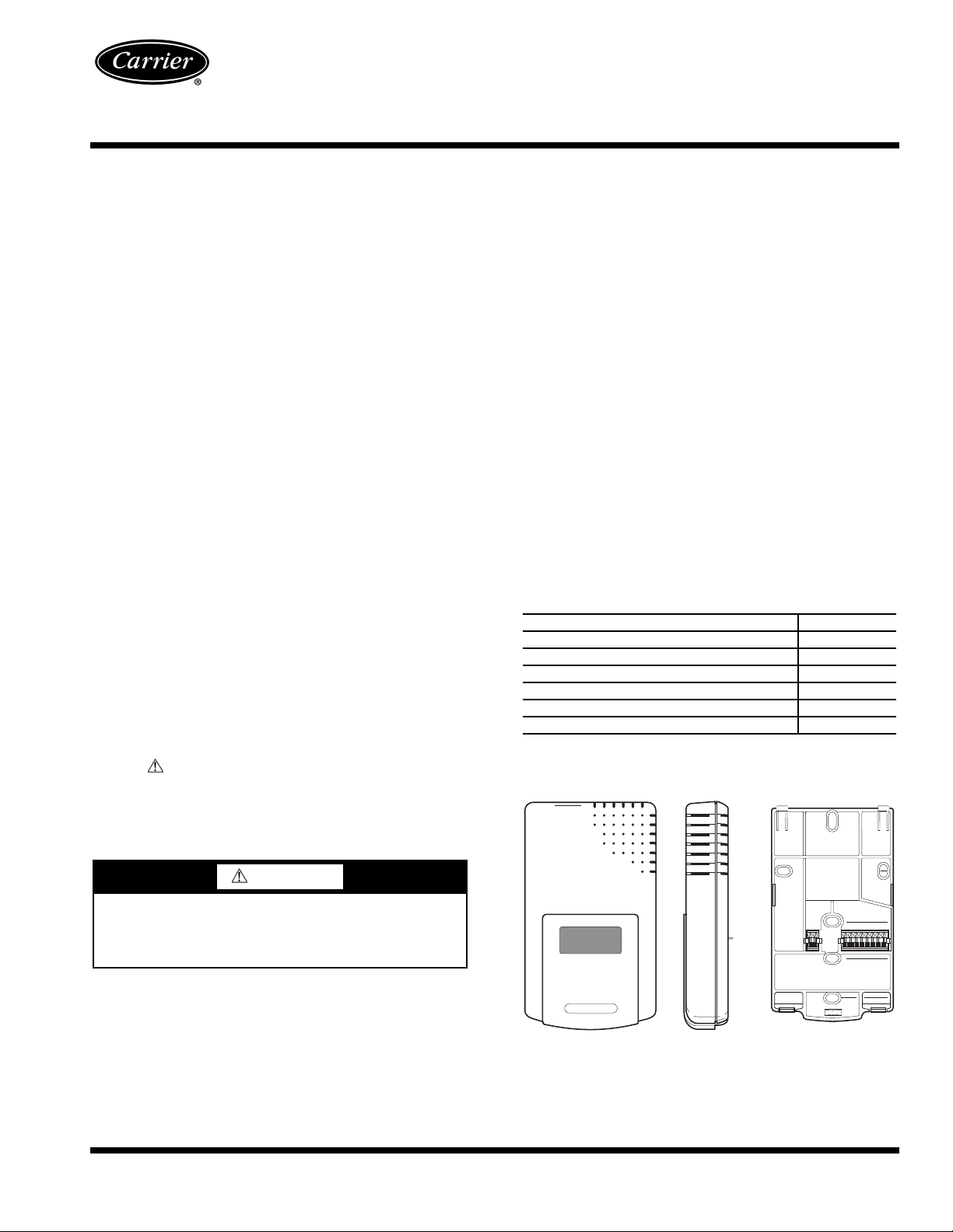
FRONT VIEW
SIDE VIEW
MOUNTING PLATE
Fig. 1 — CO2 Sensor
CO2 Sensor Accessory
Installation Start-Up and
Service Instructions
Part No. CRCBDIOX002A00
48/50Z030-105
CONTENTS
SAFETY CONSIDERATIONS . . . . . . . . . . . . . . . . . . . . . . 1
GENERAL . . . . . . . . . . . . . . . . . . . . . . . . . . . . . . . . . . . . . . . . 1
Check Package Contents. . . . . . . . . . . . . . . . . . . . . . . . . 1
INSTALLATION . . . . . . . . . . . . . . . . . . . . . . . . . . . . . . . . . . 2,3
START-UP . . . . . . . . . . . . . . . . . . . . . . . . . . . . . . . . . . . . . . . . 4
Configuring the ComfortLink™ Controller. . . . . . . . 4
Verification and Calibration . . . . . . . . . . . . . . . . . . . . . . 4
SERVICE . . . . . . . . . . . . . . . . . . . . . . . . . . . . . . . . . . . . . . . . . 4
Cleaning . . . . . . . . . . . . . . . . . . . . . . . . . . . . . . . . . . . . . . . . . 4
TROUBLESHOOTING. . . . . . . . . . . . . . . . . . . . . . . . . . . . . 4
SAFETY CONSIDERATIONS
Installing, starting up and servicing HVAC (heating, ventilation, and air conditioning) equipment can be hazardous due to
system pressures, electrical components and equipment
locations.
Only trained, qualified installers and service technicians
should install, start up and service this equipment.
When working on HVAC equipment, observe precautions
in the literature, labels attached to the equipment and any other
safety precautions that apply. Follow all safety codes. Wear
safety glasses and work gloves. Use care when handling and
installing the sensor.
Understand the signal words DANGER, WARNING, and
CAUTION. These words are used with the safety alert
symbol . DANGER identifies the most serious hazards
which will result in severe personal injury or death.
WARNING signifies a hazard which could result in personal
injury or death. CAUTION is used to identify unsafe practices
which would result in minor personal injury or property
damage.
The unit utilizes a 4 to 20-mA analog signal. The ComfortLink
controller uses this signal to control the economizer damper
position and ensure adequate level of outside air in the
building. This is one of several approved methods of controlling the indoor-air quality (IAQ) in a building and meets the
requirements of local building codes and ASHRAE (American
Society of Heating, Refrigerating and Air Conditioning
Engineers) Standard 62. The control sensor features a membrane-covered waveguide and sample chamber that produces
stable, reliable, and highly accurate carbon dioxide readings.
The sensor is self-calibrating and should not need to be
manually calibrated.
Check Package Contents — Remove accessory pack-
aging and inspect shipment for damage. If any damage is found,
file a claim with the shipping agent immediately. If any item is
missing or any part does not assemble properly, notify your
Carrier distributor. Table 1 lists the accessory package contents.
Table 1 — Accessory Package Contents
ITEM QUANTITY
CO
Sensor (Part No. HH99ZZ019) 1
2
Bracket (48/50A) 1
No. 8-18 x
1
/4 AB-14 x 5/8 Screw 2
Electrical Harness* 1
Bracket (48/50P,48/50Z) 1
*Do not use the electrical harness provided in this kit for 48/50P and
48/50Z units.
1
/4 Screw 2
WARNING
Prior to installation of this accessory, make sure all power
is disconnected to the unit and locked out. Failure to disconnect power supply prior to servicing may result in serious injury.
GENERAL
The CO2 sensor (Fig. 1) is designed to monitor carbon
dioxide (CO
ComfortLink™ controller on the rooftop air-conditioning unit.
The sensor perceives CO
million (ppm) range and provides outputs indicating this level.
Catalog No. 04-53480064-01 Printed in U.S.A. Form 48/50-73SI Pg 1 8-09 Replaces: 48/50A-4SI
) levels in the return air and interface with the
2
levels in the 0 to 2,000 parts per
2
Manufacturer reserves the right to discontinue, or change at any time, specifications or designs without notice and without incurring obligations.
Page 2
INSTALLATION
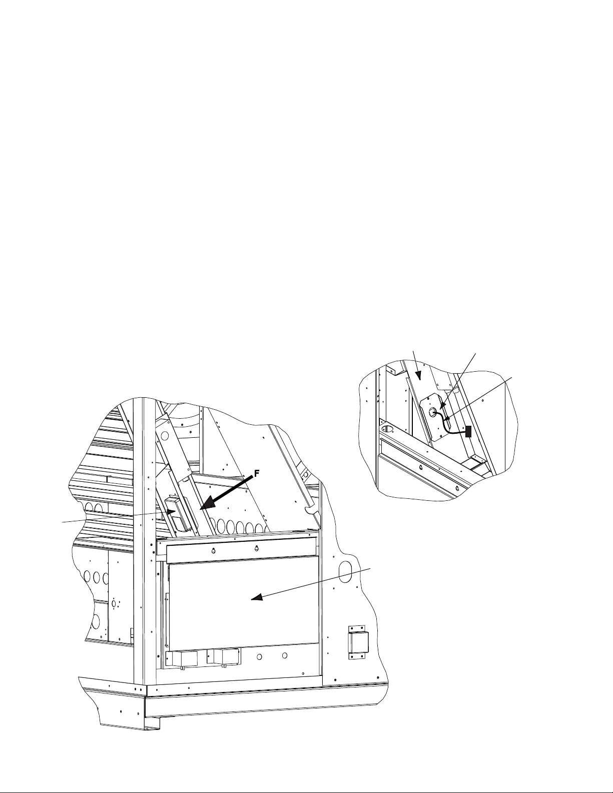
CO
2
SENSOR
AUXILIARY
CONTROL BOX
PARTITION
BRACKET
(48/50A)
ELECTRICAL
HARNESS
Fig. 2 — 48/50A CO2 Sensor Mounting Location
VIEW F
48/50A Units —
predrilled holes located above the auxiliary control box (see
Fig. 2).
1. Shut off unit power supply.
2. Open the hinged auxiliary control box access door and
secure.
3. Remove the sensor and cover from the sensor mounting
plate.
4. Secure mounting plate to bracket (48/50A) with no. 8
screws (see Fig. 3).
5. Wire the electrical harness to the sensor as shown in
Fig. 3 and 4.
6. Remove the blankout plate from the partition, just above
the auxiliary control box.
7. Attach the sensor to the mounting plate.
8. Mount the bracket to the partition using 2 sheet metal
screws (see view F in Fig. 2).
9. Connect the electrical harness (PL18).
10. Restore power to unit.
The CO2 sensor is to be installed in the
48/50P and 48/50Z Units — The CO
sensor is to be
2
installed in the predrilled holes located in the power exhaust
section. See Fig. 5-11.
1. Shut off unit power supply.
2. Open the power exhaust section doors/panels to gain
access.
3. Remove the sensor and cover from the sensor mounting
plate.
4. Secure mounting plate to the bracket with no. 8 screws.
5. The electrical wire harness for the CO
sensor is factory
2
installed. Locate the four wires in the power exhaust
section. Wire the electrical harness to the sensor as shown
in Fig. 4.
6. Attach the sensor to the mounting plate.
Mount the bracket to the appropriate location:
size 030-050 units with power exhaust, see Fig. 5 and 6.
size 030-050 units with economizer only, see Fig. 7.
size 030-050 units with no economizer or power exhaust,
see Fig. 8.
48/50P055-100 and 48/50Z055-105 units with power exhaust, see Fig. 9.
48/50P055-100 and 48/50Z055-105 units with economizer only, see Fig. 10.
48/50P055-100 and 48/50Z055-105 units with no economizer or power exhaust, see Fig. 11.
2
Page 3

7. Restore power to unit.
CO2 SENSOR
AND BRACKET
PL18
(48/50A
ONLY)
BRACKET
(48/50A)
SENSOR MOUNTING PLATE
HOLES MUST LINE-UP
COVER SCREW
SENSOR COVER
CO2 SENSOR
AND
BRACKET
Fig. 7 — CO2 Bracket for 48/50P030-050 and
48/50Z030-050 Units (Economizer Only)
Fig. 6 — CO
2
Bracket for 48/50P030-050 and
48/50Z030-050 Units Side View (Economizer with
Power Exhaust)
Fig. 3 — CO
2
Sensor Assembly
Fig. 4 — Harness Wiring Connections
Fig. 5 — CO
2
Bracket for 48/50P030-050 and
48/50Z030-050 Units (Economizer with Power
Exhaust)
Fig. 8 — CO
2
Bracket for 48/50P030-050 and
48/50Z030-050 Units (No Economizer or Power
Exhaust)
CO2 SENSOR
CO2 SENSOR
AND BRACKET
AND BRACKET
3
CO2 SENSOR
AND BRACKET
Page 4

CO2 SENSOR
AND BRACKET
CO2 SENSOR
AND BRACKET
Fig. 10 — CO2 Bracket for 48/50P055-100 and
48/50Z055-105 Units (Economizer Only)
Fig. 11 — CO
2
Bracket for 48/50P055-100 and
48/50Z055-105 Units (No Economizer or Power
Exhaust)
Fig. 9 — CO
2
Bracket for 48/50P055-100 and
48/50Z055-105 Units (Economizer with Power
Exhaust)
CO2 SENSOR
AND BRACKET
START-UP
After applying power, the CO2 sensor will enter a warm-up
mode. Warm-up duration will be from 1 to 10 minutes. The
warm-up duration will be shorter in warmer temperatures and
longer in cooler temperatures. During warm-up, the signal
output will be 4 mA. Once the unit has warmed up, the voltage
or current output will be set up to indicate the CO
display will show a steady reading 1 minute later.
level. The
2
Configuring the ComfortLink™ Controller —
The CO2 sensor is defaulted to provide 4 mA at 0 ppm and
20 mA at 2000 ppm. If a different range is necessary, contact
Carrier Application Engineering to reconfigure the sensor. If
the sensor is reconfigured, the mA range on the ComfortLink
controller must be configured to match the new values. Refer
to Controls and Troubleshooting Guide for configuration
details.
Sensor Self Calibration — The CO
self-calibration system. The system eliminates the need for
manual calibration in applications where the indoor CO
drops to outside levels during unoccupied periods (e.g., during
evening hours). A special software routine in the sensor remembers the background readings for 14 consecutive evenings, calculates if there is a sensor drift, and then corrects for
it.
NOTE: This only applies when used in typical indoor or ambient air conditions. Consult Carrier application engineering if
other gases or corrosive agents are part of the application
environment.
sensors employ a
2
level
2
SERVICE
Cleaning —
that requires very little maintenance. Clean external surfaces
periodically with a dampened cloth.
The controller is a rugged and lightweight unit
TROUBLESHOOTING
The following occurrences may indicate abnormal operation, caused primarily by power input fluctuations, surges, or
spikes.
• The unit remains in warm-up mode for more than
10 minutes.
• The LED glows with no pulse.
•CO
indication (display numbers or signal output) is
2
frozen.
• Numbers on the display change continuously for longer
than 1 minute.
Normal operation can usually be restored by removing
power, shutting down the unit for at least 15 seconds, then
reconnecting power. The unit should warm up, as described
above, then return to normal operation. If the situation
continues, remove and replace the sensor.
Copyright 2009 Carrier Corporation
Manufacturer reserves the right to discontinue, or change at any time, specifications or designs without notice and without incurring obligations.
Catalog No. 04-53480064-01 Printed in U.S.A. Form 48/50-73SI Pg 4 8-09 Replaces: 48/50A-4SI
 Loading...