

Carrier 48/50HC04-28, 48/50TC04-30, 50TCQ04-24, 50HCQ04-12, 48/50LC04-26 Controls, Start-up, Operation And Troubleshooting
Page 1

48/50TC04 ---30, 50TCQ04---24
48/50HC04---28, 50HCQ04---12
48/50LC04---26
Factory Installed Option
RTU Open
Multi --- Protocol Controller
Controls, Start---Up, Operation
and Troubleshooting
TABLE OF CONTENTS
SAFETY CONSIDERATIONS 2.........................
GENERAL 2.........................................
SENSOR/ACCESSORY INSTALLATION 2................
Sensors and Accessories 4.............................
User Interfaces 4.....................................
Install Analog Sensors 4...............................
Supply Air Sensor (SAT) 4...........................
Outdoor Air Sensor (OAT) 4..........................
Space Temperature Sensor (SPT) 4.....................
Sensor Averaging 9...............................
CO
Sensor(s) (IAQ and OAQ) 9......................
2
Relative Humidity Sensors (Space or Duct Mounted) 11.....
Installing Discrete Inputs 11............................
Compressor Safety 11...............................
Humidistat 11.....................................
Single Enthalpy (Outdoor Enthalpy) 11.................
Differential Enthalpy 11.............................
Fire Shutdown 12..................................
Filter Status 12.....................................
Fan Status 12......................................
Remote Occupancy 12...............................
IGC Override 12...................................
Communication Wiring--Protocols 13.....................
General 13........................................
R
Building Automation System 13.................
i--Vu
R
BACnet
Modbus 14.......................................
Johnson N2 14.....................................
LonWorks 14......................................
Local Access 15....................................
START--UP 16........................................
Additional Installation/Inspection 16.....................
Power Exhaust Relay Power 16........................
Service Test 16......................................
Fan Test 16.......................................
High Speed Fan Test 16..............................
Compressor 1 and Compressor 2 Test 16.................
Heat 1 and Heat 2 Test 16............................
MS/TP 13................................
Dehumidification Test 16.............................
Power Exhaust Test 17..............................
Economizer Test 17.................................
VFD Speed Test 17.................................
Configuration 17....................................
Setpoint 17.......................................
Unit 17..........................................
Inputs 18.........................................
Service Configuration 19.............................
OPERATION 20......................................
Occupancy 20.......................................
Indoor (Supply) Fan 21...............................
Cooling 21.........................................
Supply Fan 22......................................
Economizer 22......................................
Enthalpy Control 22..................................
Space Air Quality 23.................................
Power Exhaust 23....................................
Pre--Occupancy Purge 23..............................
Heating 23.........................................
Indoor Air Quality 23.................................
Dehumidification 24..................................
Demand Limit 24....................................
Unoccupied Free Cooling 24...........................
Optimal Start 24.....................................
Fire Shutdown 24....................................
Compressor Safety 24.................................
Fan Status 25.......................................
Filter Status 25......................................
Door Switch 25......................................
Remote Occupancy 25................................
Linkage 25.........................................
TROUBLESHOOTING 25..............................
General 25.........................................
Replacing the RTU Open’s Battery 25...................
Thermistor Troubleshooting 26.........................
Software Version 26..................................
Communication LED’s 26.............................
Alarms 29..........................................
Performance 31......................................
Page 2
Third Party Networking 32.............................
APPENDIX A -- USER INTERFACE MENUS 33............
APPENDIX B -- THIRD PARTY POINTS LIST 41..........
APPENDIX C -- EQUIPMENT TOUCH
NAVIGATION SCREENS 45..............
RTUOPENSTART--UPSHEET 49.......................
SAFETY CONSIDERATIONS
Installation and servicing of air-conditioning equipment
can be hazardous due to system pressure and electrical
components. Only trained and qualified service personnel
should install, repair, or service air-conditioning
equipment. Untrained personnel can perform the basic
maintenance functions of replacing filters. Trained service
personnel should perform all other operations.
When working on air-conditioning equipment, observe
precautions in the literature, tags and labels attached to
the unit, and other safety precautions that may apply.
Follow all safety codes. Wear safety glasses and work
gloves. Have fire extinguisher available. Read these
48---50LHTCQ---01T
instructions thoroughly and follow all warnings or
cautions attached to the unit. Consult local building codes
and National Electrical Code (NEC) for special
requirements.
Recognize safety information. This is the safety--alert
symbol
instructions or manuals, be alert to the potential for
personal injury.
Understand the signal words DANGER, WARNING, and
CAUTION. These words are used with the safety--alert
symbol. DANGER identifies the most serious hazards
which will result in severe personal injury or death.
WARNING signifies a hazard which could result in
personal injury or death. CAUTION is used to identify
unsafe practices which may result in minor personal
injury or product and property damage. NOTE is used to
highlight suggestions which will result in enhanced
installation, reliability, or operation.
ELECTRICAL SHOCK HAZARD
Failure to follow this warning could result in personal
injury or death.
Disconnect all power to the unit before performing
maintenance or service. Unit may automatically start
if power is connected.
. When you see this symbol on the unit and in
!
WARNING
GENERAL
The RTU Open controller is an integrated component of
the Carrier rooftop unit. Its internal application
programming provides optimum performance and energy
efficiency. RTU Open enables the unit to run in 100%
stand--alone control mode, Carrier’s i--Vu
or a Third Party Building Automation System (BAS).
On--board DIP switches allow you to select your protocol
(and baud rate) of choice among the four most popular
protocols in use today: BACnet
and LonWorks. (See Fig. 1.)
NOTE: Lon Works requires addition of LonWorks
Option card.
Carrier’s diagnostic display tools such as Equipment
Touch or Field Assistant can be used with the RTU Open
controller. Access is available via a 5--pin J12 access port
or Rnet communication network.
R
R
Open network,
, Modbus, Johnson N2
SENSOR/ACCESSORY
INSTALLATION
There are a variety of sensors and accessories available
for the RTU Open. Some of these can be factory or field
installed, while others are only field installable. The RTU
Open controller may also require connection to a building
network system or building zoning system. All field
control wiring that connects to the RTU Open must be
routed through the raceway built into the corner post of
the unit or secured to the unit control box with electrical
conduit. The unit raceway provides the UL required
clearance between high and low-voltage wiring. Pass the
control wires through the hole provided in the corner post,
then feed the wires thorough the raceway to the RTU
Open. Connect the wires to the removable Phoenix
connectors and then reconnect the connectors to the board.
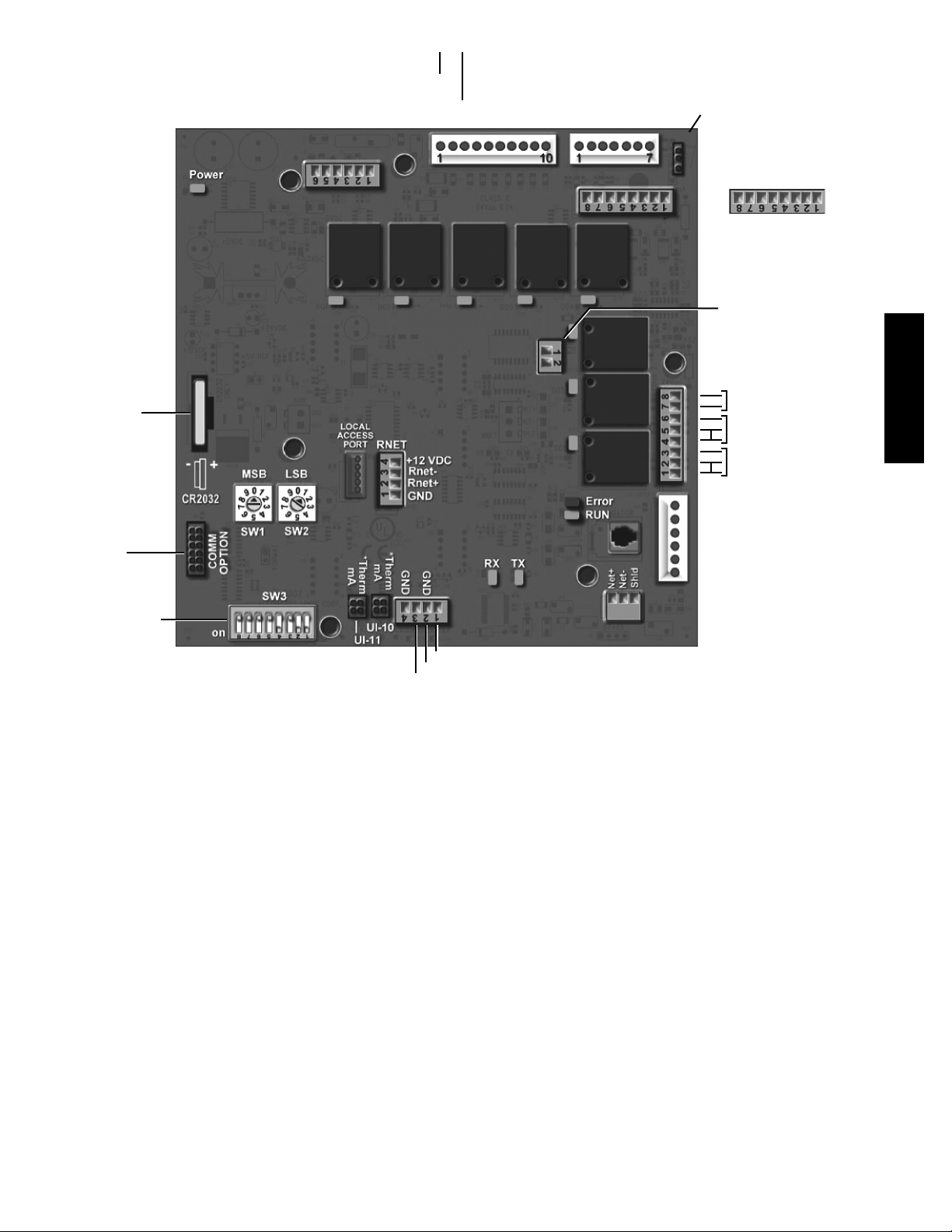
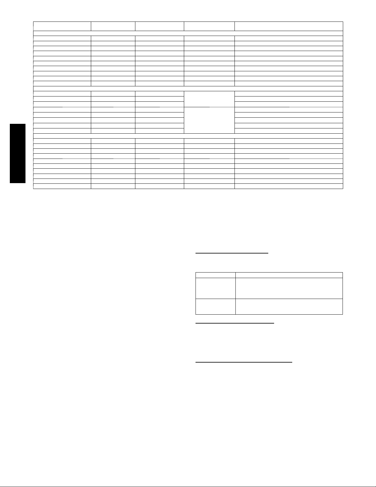
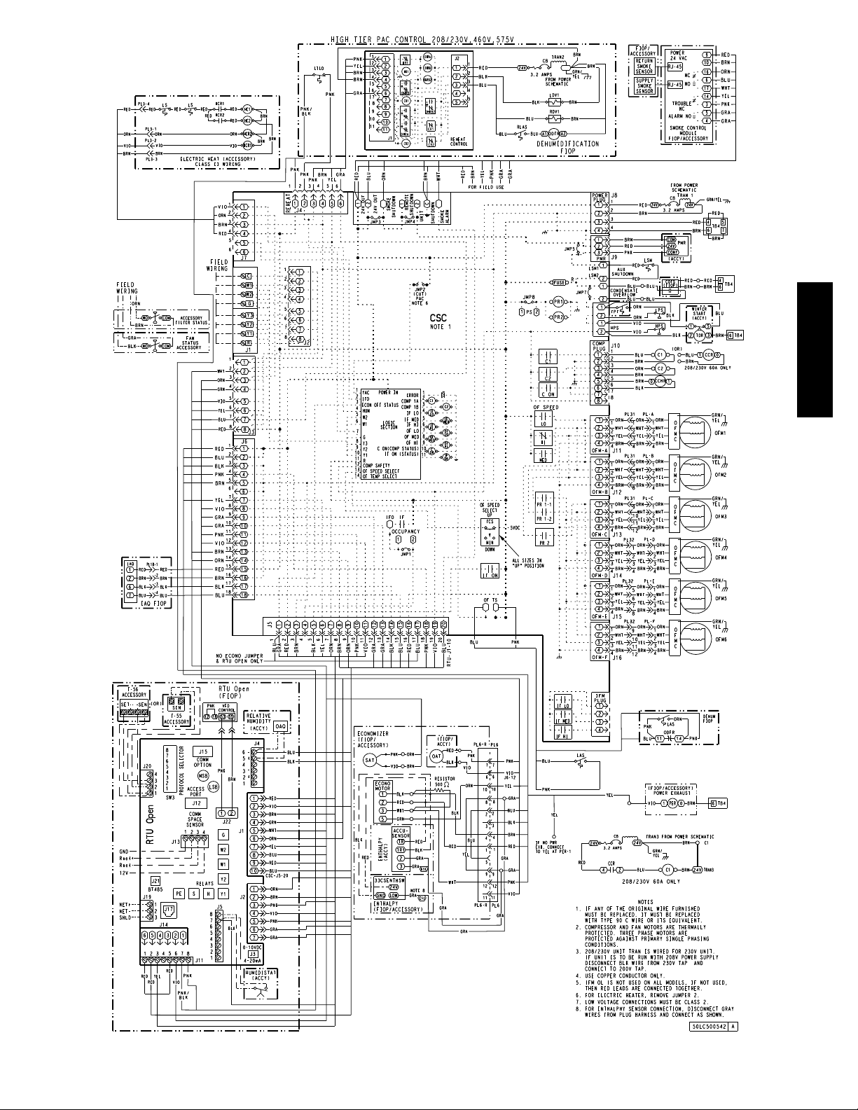
See Fig. 1 and Table 1 for board connections and Fig. 2
Through Fig. 5 for Typical Factory RTU Open wiring.
IMPORTANT: Refer to the specific sensor or accessory
instructions for its proper installation and for rooftop unit
installation refer to base unit installation instructions and
the unit’s wiring diagrams.
!
WARNING
ELECTRICAL SHOCK HAZARD
Failure to follow this warning could result in personal
injury, death and/or equipment damage.
Disconnect electrical power and use lock--out tags
before wiring the RTU Open controller.
2
Page 3
Input_2 (CO2/RH)
Input_1 (CO2/RH)
+24 VDC
Gnd
Gnd
+24 VDC
Board Power
24 VAC IN
BO-2 (W2)
BO-1 (G)
Gnd
Input_3 (X)
BO-3 (W1)
BO-4 (Y2)
BO-5 (Y1)
Input_5 (SMK)
Input_4 (R)
Input _8 (Enthalpy)
AO-1 (ECON)
Configurable - Input_8
Configurable - Input_5
Configurable - Input_3
Input_9 (Humidistat)
Gnd
24 VAC
(AO-1)
(OAT)
(SAT)
Gnd
3-Volt
Lithium
Battery
LonWorks
Option Card
Port
J4
BO-1 BO-2 BO-3 BO-4 BO-5
J22
AO-2
GND
(2-10V)
J13
J12
J17
J2J1
BO-6
BO-7
BO-8
Network Comm
0-10VDC
24 VAC
24 VAC
24 VAC
J3
4-20mA
J5 J5
J22
VFD Output
J11
BO-6
(H) Humidimizer
BO-7
(Reversing Valve/High Speed Fan/Y3)
BO-8
(Power Exhaust)
24 VAC
48---50LHTCQ---01T
Example set for
BACnet MS/TP
and 76.8K baud
(1, 2, and 4 ON)
Recommended for all
i-Vu Open installations
J15
J20
Protocol Selector SPT (temp input) BACnet, Modbus, or N2
*Remove
both for 0-5V
SPT (common)
SPT (offset input)
J19
(LON connection J15)
J14
Fig. 1 -- RTU Open Control Module
C14129
3
Page 4
POINT NAME
Space Temp / Zo ne Temp zone_temp AI (10K Thermistor) J 2 0 --- 1 & 2 Analog Input 10
Supply Air Temperature sa_temp AI (10K Thermistor) J 2 --- 1 & 2 Analog Input 6
Outside Air Temperature oa_temp AI (10K Thermistor) J 2 --- 3 & 4 Analog Input 7
Space Temperature Offset Pot stpt_adj_offset AI (100K Potentiometer) J2 0 --- 3 & 4 Analog Input 11
Safety Chain Feedback safety_status BI (24 VAC) J 1 --- 9 Binary Input 4
Compressor Safety Status
Fire Shutdown Status firedown_status BI (24 VAC) J 1 --- 1 0 Binary Input 5
Enthalpy Status enthalpy_status BI (24 VAC) J 2 --- 6 & 7 Binary Input 8
Humidistat Input Status humstat_status BI (24 VAC) J 5 --- 7 & 8 Binary Input 9
Zone Temperature n/a n/a J 1 3 --- 1 --- 4 Rnet
Indoor Air CO2 iaq A I ( 4 --- 2 0 m A )
Outdoor Air CO2 oaq A I ( 4 --- 2 0 m A ) Analog Input 1
Space Relative Humidity space_rh A I ( 4 --- 2 0 mA ) Analog Input 10
Supply Fan Status
Filter Status
Door Contact
Remote Occupancy input
IGC input
Economizer Output econ_output AO (4---20mA) J2 --- 5 Analog Output 1
Supply Fan VFD vfd_output A O ( 2 --- 1 0 V d c ) J 2 2 --- 1 & 2 Analog Output 2
Supply Fan Relay sfan BO Rela y (24VAC, 1A) J 1 --- 4 Bina ry Output 1 (G)
Cool 1 Relay State comp_1 BO Relay (24VAC, 1A) J 1 --- 8 Binary Output 5 (Y1)
Cool 2 Relay State comp_2 BO Relay (24VAC, 1A) J 1 --- 7 Binary Output 4 (Y2)
Cool 3 Relay State comp_3 BO Relay (24VAC, 1A) J 1 1 --- 5 & 6 B inary Output 7 (Y3)
Heat 1 Relay State heat_1 BO Relay (24VAC, 1A) J 1 --- 6 B inary Output 3 (W1)
Heat 2 Relay State heat_2 BO Relay (24VAC, 1A) J 1 --- 5 B inary Output 2 (W2)
48---50LHTCQ---01T
Power Exhaust Relay State pexh BO Relay (24VAC, 1A) J11---2&3(N.O.) Binary Output 8 (PE)
Dehumidification Relay dehum BO Relay (24VAC, 1A) J11---7&8(N.O.) Binary Output 6
(1)
Safety Chain Feedback: 24 Vac required at this terminal to provide “Run Enable” status. See Input/Output section for additional instructions.
(2)
These inputs are conf igurable. If installed, they take the place of the default input on the specific channel. See appropriate Input Configuration S ection for wiring and setup instructions.
(3)
Pa r a l l e l p i n s J 5 --- 1 = J 2 --- 6 , J 5 --- 3 = J 1 --- 1 0 , J 5 --- 5 = J 1 --- 2 a r e u s e d f o r f i l e d i n s t a l l a t i o n .
(4)
Refer to the input configuration and accessory sections f or more detail.
(2)
(2)
(1)
(2)
(2)
(2)
BACnet OBJECT
NAME
comp_status BI (24 VAC) J 1 --- 2 Binary Input 3
sfan_status BI (24 VAC)
filter_status BI (24 VAC) BinaryInput3,5,8,or9,exceptwhereintrinsicinputisused
door_contact_status BI (24 VAC) BinaryInput3,5,8,or9,exceptwhereintrinsicinputisused
occ_contact_status BI (24 VAC) BinaryInput3,5,8,or9,exceptwhereintrinsicinputisused
igcovr_status BI (24 VAC) Binary Input 9. Mandatory input on gas heat units.
TYPE OF I/O
DEDICATED INPUTS
CONFIGURABLE INPUTS
Sensors and Accessories
The RTU Open controller is configurable with the
following field-supplied sensors:
NOTE: Supply air temperature sensor (33ZCSENSAT) is
factory-installed.
S Space temperature sensor (ZS--CAR, ZS--C--CAR,
ZS--H--CAR, ZS--HC--CAR, ZSPL--C--CAR,
ZSPL--H--CAR, ZSPL--HC--CAR, ZSP--CAR,
ZSP--C--CAR, ZSP--H--CAR, ZSP--HC--CAR ,
33ZCT55SPT, 33ZCT56SPT, or 33ZCT59SPT)
S Indoor air quality sensor (ZS--C--CAR, ZS--HC--CAR,
Z S P L -- C -- C A R , Z S P L -- H C -- C A R , Z S P -- C -- C A R ,
ZSP--HC--CAR, 33ZCSPTCO2--01,
33ZCSPTCO2LCD--01, 33ZCT55CO2--02, or
33ZCT56CO2--02) required for demand control
ventilation.
S Outdoor air quality sensor (33ZCSPTCO2--01,
33ZCSPTCO2LCD--01)
aspirator box (C33ZCCASPCO2) required for CO
S CO
2
return duct/outside air applications
S Outdoor air enthalpy switch (33CSENTHSW)
S Return air enthalpy sensor (33CSENTSEN) required for
differential enthalpy control
S Space relative humidity sensor (33ZCSENSRH-02)
S Duct relative humidity (33ZCSENDRH-02)
S Humidistat (--HL--38MG-029) (not permitted for use on
48LC 07--26 units due to same input as IGC input)
S Smoke Detectors (CRSMKSEN002A00,
CRSMKKIT002A00)
S Fan and/or Filter Status (CRSTATUS001A00,
CRSTATUS005A00)
CONNECTION PIN
J 4 --- 2 & 3 o r J 4 --- 5 & 6
J 5 --- 1 & 2 o r J 5 --- 3 & 4 ,
J 5 --- 5 & 6 o r J 5 --- 7 & 8
OUTPUTS
User Interfaces
S Field Assistant (USB-TKIT required)
S Wall mounted Equipment Touch
S Wall mounted System Touch
Install Analog Sensors
Supply Air Sensor (SAT)
The factory supplies the discharge (supply) air sensor with
the unit and is pre--wired.
LC 04--- 12
HC/TC 04--- 16
HCQ 04 --- 12
T C Q 0 4 --- 1 4
LC 14--- 26
HC 17--- 24
TC/TCQ 17 ---30
OutdoorAirSensor(OAT)
The OAT is supplied with the economizer option or
accessory. It is wired through the 12-pin plug (PL6) in the
return air section of the unit and is mounted on the
2
economizer assembly.
Space Temperature Sensor (SPT)
There are 2 types of space temperature sensors available
from Carrier, resistive input non-communicating (T55, T56,
and T59) and Rnet communicating (ZS--CAR, ZS--C--CAR,
ZS--H--CAR, ZS--HC--CAR, ZSPL--C--CAR, ZSPL--H--CAR,
Z S P L -- H C -- C A R , Z S P -- C A R , Z S P -- C -- C A R , Z S P -- H -- C A R ,
ZSP--HC--CAR) sensors. Each type has a variety of options
consisting of: timed override button, set point adjustment, a
LCD screen, combination of humidity or CO
communication tie in. Space temperature can be also be
written to from a building network or zoning system.
However, it is still recommended that return air duct sensor
be installed to allow stand-alone operation for back-up.
NUMBER(S)
(4)
Unit/Size SAT Shipping Location/Installation Location
CHANNEL DESIGNATION
Analog Input 2
BinaryInput3,5,8,or9,exceptwhereintrinsicinputisused
(3)
The SAT is secured to the unit’s supply duct opening.
This sensor must be relocated into the supply duct
during unit installation.
The SAT is mounted through the side of the heat
chamber below the fan deck, and does NOT require
relocation.
Refer to the configuration section for details on controller
configurations associated with space sensors.
4
Table 1 – RTU Open Inputs and Outputs
sensing and
2
Page 5
48---50LHTCQ---01T
Fig. 2 -- Typical Factory Option Wiring -- 50LC 14--26 Shown
5
C14119
Page 6
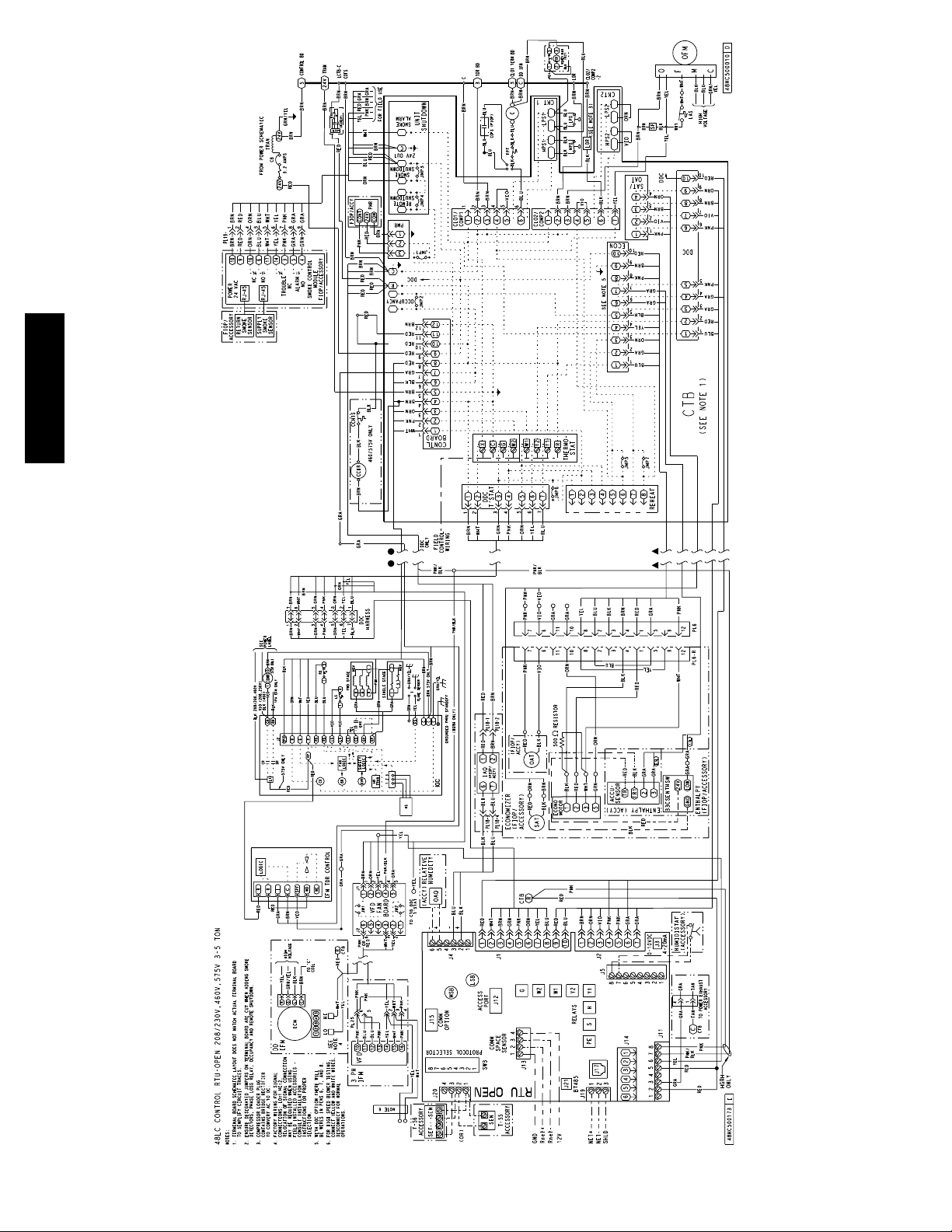
48---50LHTCQ---01T
Fig. 3 -- Typical Factory Option Wiring -- 48LC 04--06 Shown
6
C14146
Page 7
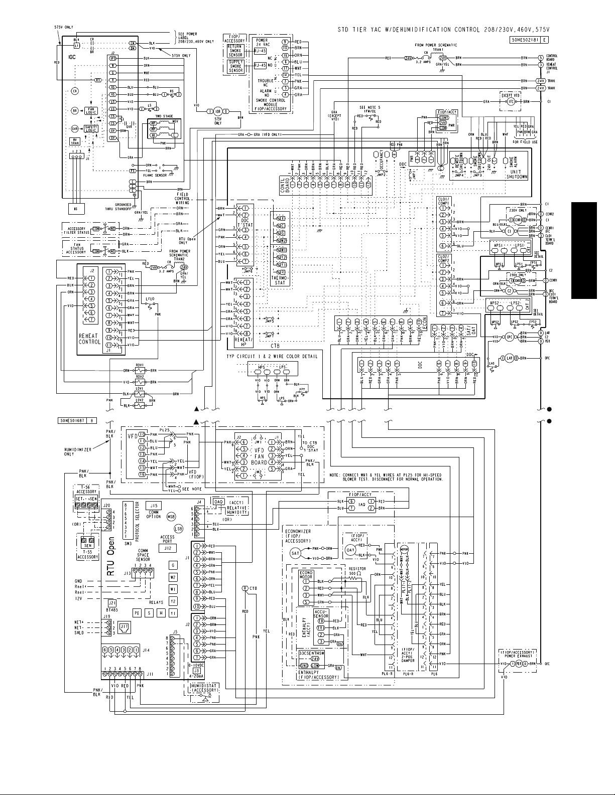
48---50LHTCQ---01T
Fig. 4 -- Typical Factory Option Wiring -- 48TC 17--30 Shown
7
C13768
Page 8
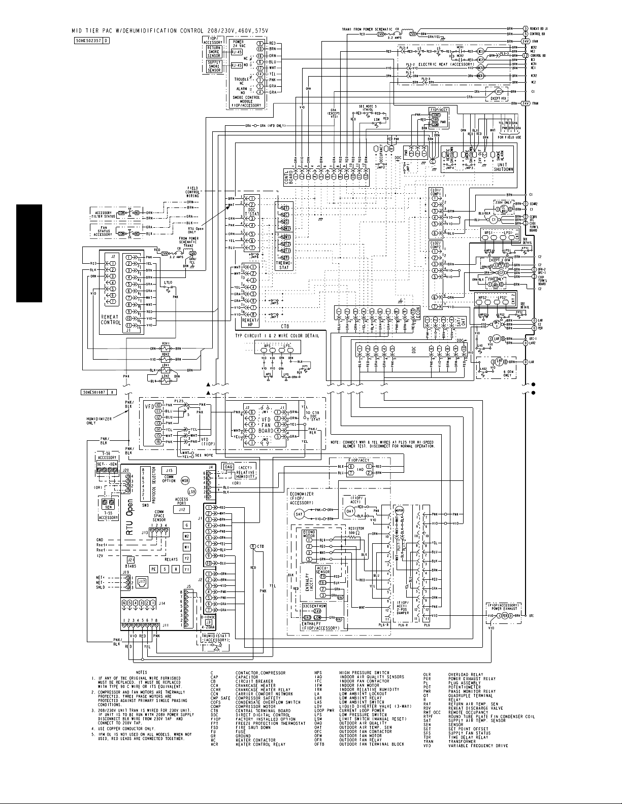
48---50LHTCQ---01T
Fig. 5 -- Typical Factory Option Wiring -- 50HC 17--28 Shown
8
C13668
Page 9
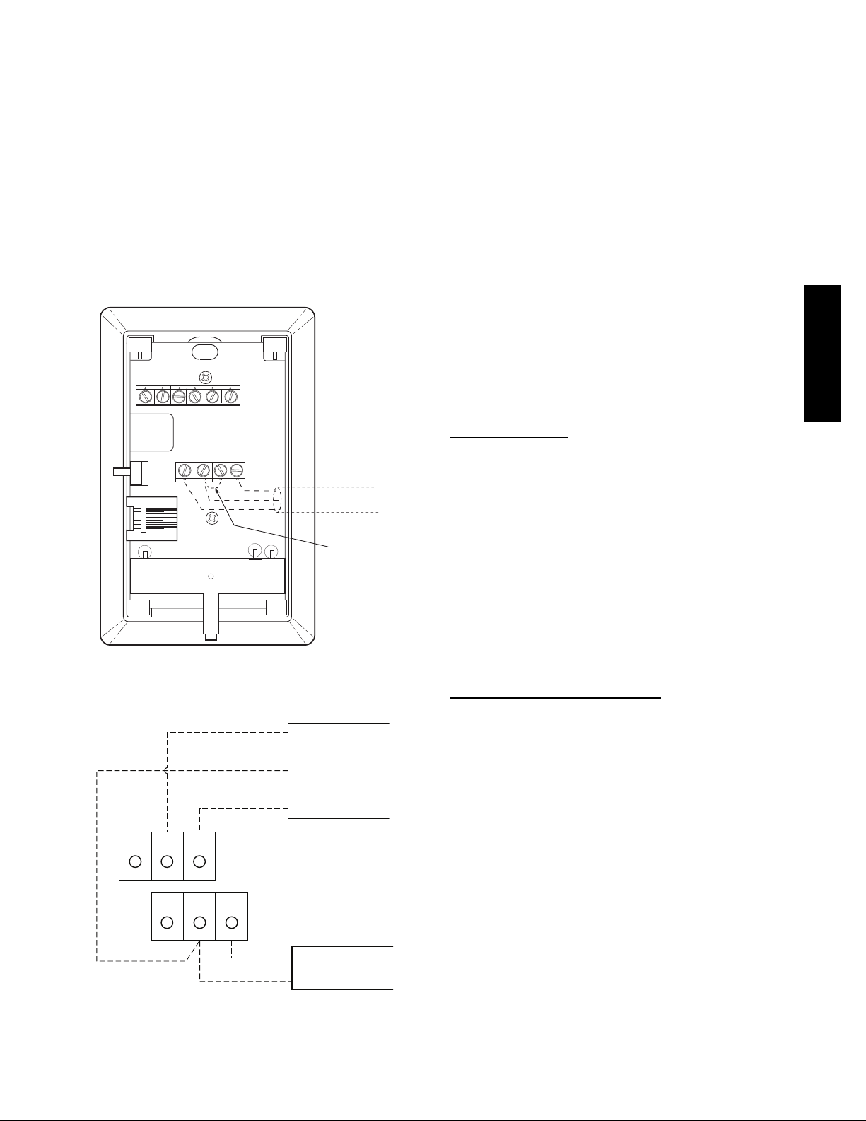
Resistive Non--Communicating Sensor Wiring
For sensor with setpoint adjustment up to 1000 ft (305m),
use three-conductor shielded cable 20 gauge wire to
connect the sensor to the controller. For non set point
adjustment (slidebar) or return air duct sensor, an
unshielded, 18 or 20 gauge, two-conductor, twisted pair
cable may be used. Below is the list of the connections of
the SPT to the RTU Open, refer to Fig. 6 and 7 for typical
connections at the sensor.
S J20-1 = temperature sensor input (SEN)
S J20-2 = sensor common
S J20-3 = Setpoint adjustment input (SET)
NOTE: See Fig. 8 for space temperature sensor averaging.
T55/56 Override button will no longer function when sensors
are averaged. Only Sensor 1 T56 STO input can be used.
2
3
SW1
Cool Warm
45
SEN
61
SET
BLK
(T56)
BRN (GND)
BLU (SPT)
SENSOR WIRING
JUMPER
TERMINALS
AS SHOWN
C07131
Fig. 6 -- Space Temperature Sensor
Typical Wiring (33ZCT56SPT)
BLK (STO)
BRN (COM)
BLU (SPT)
OR SET SEN
OPB COM- PWR+
24 VAC
NOTE: Must use a separate isolated transformer.
J20-3
J20-2
J20-1
SENSOR
WIRING
POWER
WIRING
C10291
Fig. 7 -- Space Temperature Sensor
Typical Wiring (33ZCT59SPT)
Rnet Communicating Sensor Wiring
The Rnet bus allows local communication with the RTU
Open, including communicating sensors. The Rnet bus
can hold up to 6 devices in the following combinations
wired in daisy-chain or hybrid configuration:
S 1-4 ZS--CAR sensor(s)
S 1 ZSPL--CAR or ZSP--CAR sensor
S 1-4 SPS sensor(s), and 1ZSPL--CAR or ZSP--CAR sensor
S Any of the above combinations, plus CO
or RH
2
combination
NOTE: Additional ZS sensors must be addressed. Use
the jumpers on the ZS sensor’s circuit board and refer to
the sensor installation instructions for addressing.
For Rnet wiring up to 500ft (152m), use 18 AWG 4
conductor unshielded plenum rated cable. The RTU Open’s
J13-RNET connection has a 4 pin Phoenix connector wired
as described below, Fig. 9 shows sensor Rnet wiring.
S RNET -- 1 = Signal ground (GND)
S RNET -- 2 = Signal (Rnet+)
S RNET -- 3 = Signal (Rnet--)
S RNET -- 4 = Power (+12v)
Sensor Averaging
Non--communicating sensors:
See Fig. 8 for space temperature sensor averaging
configurations, only combinations of 4 or 9 sensors will
operate correctly.
NOTE: T55/T56 Override button will no longer function
when sensors are averaged. Only 1 T56 STO input can be
used. Non--communication CO
sensors can not be
2
averaged.
Communicating sensors:
Any combination of sensors described in the “Rnet
Communicating Sensor Wiring” section can be used.
NOTE: Communicating CO
sensors and RH sensors can
2
be averaged if within the realm described.
CO2 Sensor(s) (IAQ and OAQ)
The indoor air quality (IAQ) and outdoor air quality
(OAQ) sensors monitor carbon dioxide (CO
information is used to monitor the quality of air in terms
of parts per million (PPM). The same sensor is used for
inside, outside, and duct monitoring, except an aspirator
box is required for outside and duct mounting. The CO
sensor is preset for a range of 0 to 2000 ppm and a linear
mA output of 4 to 20. The rooftop unit may have a factory
installed CO
sensor on the side of the economizer
2
assembly in the return air section of the unit and is
pre-wired and pre-configured at the factory. For field
installed sensors, a field supplied transformer must be
used to power the sensor. Refer to the instructions
supplied with the CO
sensor for electrical requirements
2
and terminal locations. RTU Open configurations must be
changed after adding a CO
for typical CO
sensor wiring.
2
sensor. See below and Fig. 10
2
S J4--2 or J4--5 = 4--20mA signal input
S J4--3 or J4--6 = signal common
NOTE: The factory used J4-2&3 for CO
inputs.
) levels. This
2
(IAQ) sensor
2
48---50LHTCQ---01T
2
9
Page 10
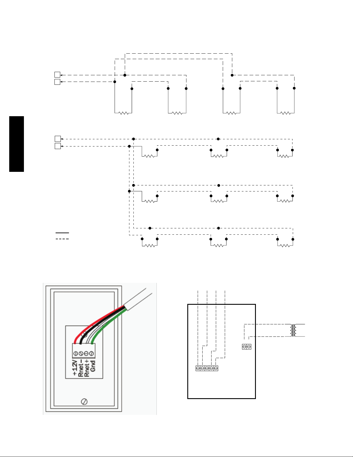
Combination Temperature and CO2Sensor
r
If using a combination temperature and CO
2
sensor
(33ZCT55CO2--02 or 33ZCT56CO2--02), refer to the
installation instructions provided with the sensor.
48---50LHTCQ---01T
J20
J20
RED
BLK
RED
1
BLK
2
RED
BLK
SENSOR 2 SENSOR 3 SENSOR 4SENSOR 1
RED
BLK
RED
BLK
SPACE TEMPERATURE AVERAGING — 4 SENSOR NON-COMMUNICATING APPLICATION
1
2
RED
BLK
BLK
BLK
SENSOR 1
RED
SENSOR 4
RED
RED
BLK
SENSOR 2
RED
BLK
SENSOR 5
RED
BLK
SENSOR 3
RED
BLK
SENSOR 6
LEGEND
Factory Wiring
Field Wiring
SENSOR 7
SPACE TEMPERATURE AVERAGING — 9 SENSOR NON-COMMUNICATING APPLICATION
Fig. 8 -- Space Temperature Averaging for Non--Communicating Sensors
C10820
Fig. 9 -- Typical Rnet Communication Sensor Wiring
RED
BLK
SENSOR 8
RED
BLK
SENSOR 9
To controller
24 Vac Line
-
8 7 6 5 4
+
2 1
24 Vac
or Vdc
Dedicated Transforme
SENSOR LEGEND
1 +24 Vac/Vdc
2 Gnd (-24 Vac/Vdc)
4 -Thermistor
5 +Thermistor
6 4-20 mA
7 SIG COM
8 0-5 Vdc
Fig. 10 -- Indoor/Outdoor Air Quality (CO2)Sensor
(33ZCSPTCO2--01 or 33ZCSPTCO2LCD--01)
Typical Wiring Diagram
C14130
C12748
10
Page 11
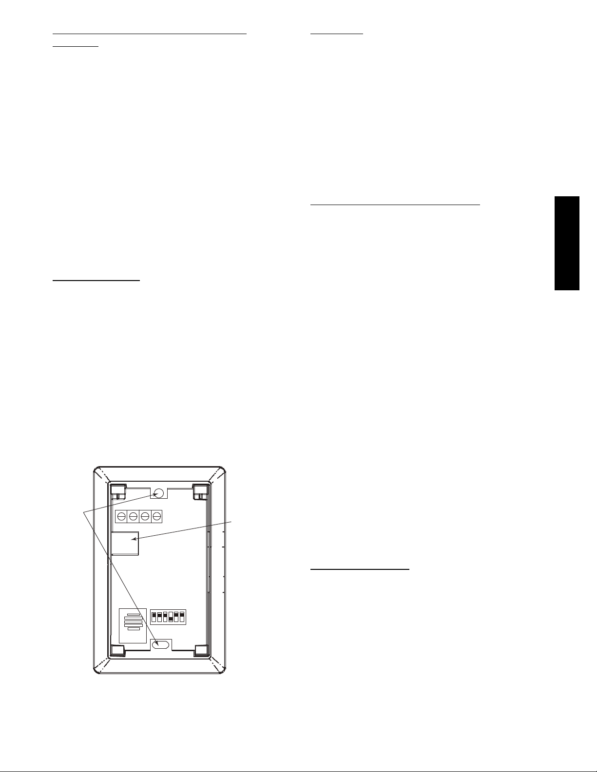
Relative Humidity Sensors (Space or Duct
Mounted)
The accessory space humidity sensor or duct humidity
sensor is used to measure the relative humidity of the air
within the space or return air duct. The RH reading is used
to control the Humidi-MiZer
R
option of the rooftop unit. For
wiring distances up to 500 ft (152m), use a 3-conductor, 18
or 20 AWG shielded cable. The shield must be removed
from the sensor end of the cable and grounded at the unit
end. The current loop power for the sensor is provided by
the RTU Open controller as 24vdc. Refer to the instructions
supplied with the RH sensor for electrical requirements and
terminal locations. RTU Open configurations must be
changed after adding a RH sensor. See below and Figs. 11 &
12 for typical non--communicating RH sensor wiring.
S J4--1 or J4--4 = 24vdc loop power
S J4--2 or J4--5 = 4--20mA signal input
NOTE: The factory default for dehumidification control
is a normally open humidistat.
Installing Discrete Inputs
Compressor Safety
The compressor safety input provides the RTU Open with
feedback to when the compressor is not running and
should be. This feedback can be provided by a
Compressor Lock-Out (CLO) device or current switch
when field installed. Compressor safety is a dedicated
input on the configurable input 3 and tells the RTU Open
when the compressor is locked out. The normal condition
for compressor safety is good operation. A normally open
compressor safety is the factory default for all units.
Follow specific accessory instructions if installing a CLO
device. The CLO should wire into the unit’s Integrated
Staging Control (ISC) board (48/50LC 07--26) or Central
Terminal Board (CTB) (all 48/50TC(Q), 48/50HC(Q), and
04--06 48/50LC units).
NOTE: Input 3 can also be wired into J--5.
MOUNTING
HOLES
Io
Gnd
Vin
Vo
SW2
123456
ON
a33-9141
Vin - J4 -1 or J4 -4 24Vdc
Io - J4 -2 or J4 -5 4 -20mA output
Fig. 11 -- Space Relative Humidity Sensor Typical Wiring
WIRING
OPENING
C07201
Humidistat
The accessory humidistat provides the RTU Open insight
to the relative humidity in the space. The humidistat reads
the RH level in the space and compares it to its setpoint to
operate a dry contact. The humidistat is a dedicated input
on the configurable input 9 and tells the RTU Open when
the RH level is HIGH or LOW. The normal condition for
humidity is LOW. A normally open humidistat is the
factory default control for the Humidi-MiZer option. To
wire in the field:
S J5--8 = 24 VAC source for dry contact
S J5--7 = Signal input
NOTE: Not permitted for use on 48LC 07--26 units due
to same input as IGC input.
Single Enthalpy (Outdoor Enthalpy)
The outdoor enthalpy switch/receiver (33CSENTHSW)
senses temperature and humidity of the air surrounding
the device and calculates the enthalpy when used without
an enthalpy sensor. The relay is energized when enthalpy
is high (above 28 BTU/lb OR dry bulb temperature is
above 75_F) and de-energized when enthalpy is low
(below 27 BTU/lb AND dry bulb temperature is below
74.5_F). The enthalpy input is dedicated to input 8 and
tells the RTU Open when the outside air enthalpy is HIGH
or LOW. The normal condition for the enthalpy input is
HIGH. Enthalpy is configured on input 8 in the factory
when it is added as an option.
NOTE: The enthalpy calculation is done using an
average altitude of 1000 ft above sea level.
For field installation, refer to the enthalpy accessory
instructions. For wiring see below and Fig. 10. The RTU
Open board provides 24vac on one of the two loose grey
wires in the return air section of the rooftop near the
12-pin economizer plug. To determine the correct grey,
measure the voltage on the wires with power applied to
the unit. If 24-vac is sensed, then that is the grey wire that
is connected to the RTU Open board at J2-7. The other is
the signal for input 8, connect it to the LOW Enthalpy
terminal on the enthalpy switch/receiver. Tie into the
12-pin economizer plug on pin 4 or the black wire
connected to the actuator for the enthalpy’s GND
connection. Power can also be provided direct from the
unit transformer and J5 terminal on the RTU Open.
S J2--7orJ5--2=24VACforenthalpyswitchpower
S J2--6 or J5--1 = input signal
Differential Enthalpy
Differential enthalpy control requires both an enthalpy
switch/receiver (33CSENTHSW) and an enthalpy sensor
(33CSENTSEN). The enthalpy sensor must be installed in
the field as the factory can only provide single enthalpy.
The enthalpy sensor must be mounted in the return
airstream and calculates the enthalpy of the indoor air.
The relay is energized when the enthalpy detected by the
return air enthalpy sensor is less than the enthalpy at the
enthalpy switch/receiver. The relay is de-energized when
the enthalpy detected by the return air enthalpy sensor is
greater than the enthalpy at the enthalpy switch/receiver
(differential enthalpy control).
48---50LHTCQ---01T
11
Page 12
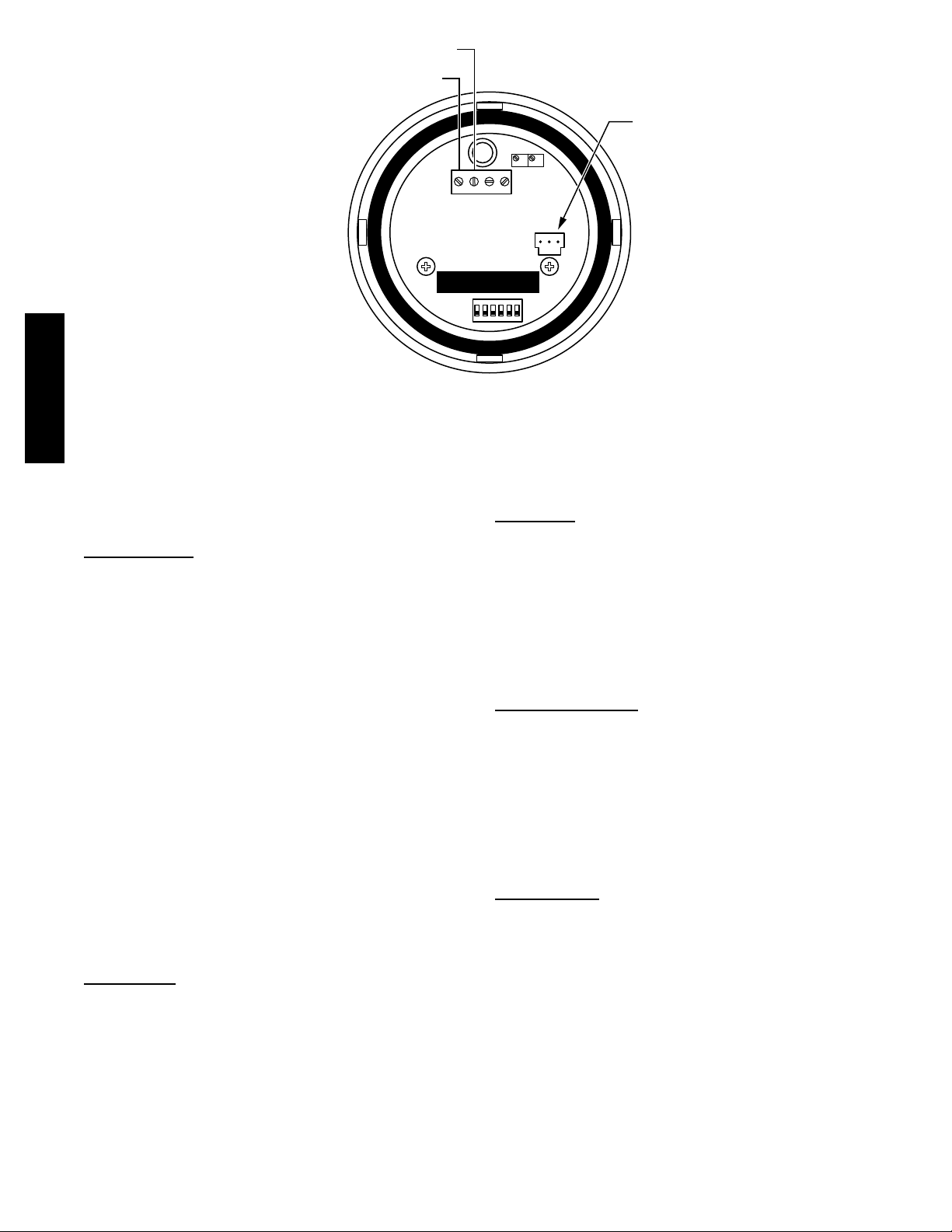
J4-1 or J4-4 + 24 VDC Supply Voltage
J4-2 or J4-5 (-)4 to 20 mA Current Loop Output
to RTU Open
Fig. 12 -- Duct Relative Humidity Sensor Typical Wiring
4-20mAVAC
VDC
or
GND 0-5V
0-10V
SPAN
or
123456
ON
Relative Humidity Sensor
(Polarized Male Connector)
ZERO
C12756
To wire return air enthalpy sensor:--MP
48---50LHTCQ---01T
Connect the 4-20 mA In terminal on the enthalpy switch/
receiver to the 4-20 mA Out terminal on the return air
enthalpy sensor. Connect the 24-36 VDC Out terminal on
the enthalpy switch/receiver to the 24-36 VDC In terminal
on the return air enthalpy sensor. (See Fig. 13.)
Fire Shutdown
The fire shutdown input is provided for unit shutdown in
response to a fire alarm or smoke detector. The fire
shutdown input is dedicated to input 5 and tells the RTU
Open when to shutdown due to smoke detection or fire
alarm system. The normal condition for fire shutdown is
there is no fire alarm. The unit may have factory installed
smoke detector(s); refer to the base unit installation
instructions for details on any adjustments required during
unit installation. Fire shutdown is always factory
configured for a normally open smoke detector.
For field installation of a smoke detector see instructions
for that specific accessory. See below and the
troubleshooting section for wiring at the unit’s Integrated
Staging Control (ISC) board (48/50LC 07--26) or Central
Terminal Board (CTB) (all 48/50TC(Q), all 48/50HC(Q),
and 04--06 48/50LC units).
S ISC or CTB -- UNIT SHUTDOWN -- 24v OUT = 24
VAC source
S ISC or CTB -- UNIT SHUTDOWN -- Smoke Alarm =
Signal input to RTU Open
NOTE: Input 5 can also be wired into J5--3.
Filter Status
The filter status accessory is a field-installed accessory.
This accessory detects plugged filters. When installing
this accessory, the unit must have a free input (input 3, 5,
8, or 9). One of the dedicated functions (Humidistat, Fire
shutdown, Enthalpy, or Compressor safety) must not be in
use to configure Filter Status. Refer to the configuration
section for details on configuring inputs for specific
functions and state. Refer to Fig. 1 for wire terminations
at J5.
Fan Status
The fan status accessory is a field-installed accessory.
This accessory detects when the indoor fan is moving air.
When installing this accessory, the unit must have a free
input (input 3, 5, 8, or 9). One of the dedicated functions
(Humidistat, Fire shutdown, Enthalpy, or Compressor
safety) must not be in use to configure Fan Status. Refer
to the configuration section for details on configuring
inputs for specific functions and state. Refer to Fig. 1 for
wire terminations at J5.
Remote Occupancy
The remote occupancy accessory is a field-installed
accessory. This accessory provides an input to change the
units occupancy status. When installing this accessory, the
unit must have a free input (input 3, 5, 8, or 9). One of the
dedicated functions (Humidistat, Fire shutdown, Enthalpy,
or Compressor safety) must not be in use to configure
remote occupancy. Refer to the configuration section for
details on configuring inputs for specific functions and
state. Refer to Fig. 1 for wire terminations at J5.
IGC Override
The IGC Override input is factory--installed for 48LC
07--26 gas heat units. This input provides an indication
that the gas valve is stuck open and the heat is still
operating after any call for heating has been dropped. This
function requires the use of input 9. Any of the other
dedicated functions (Humidistat, Fan Status, Filter Status,
Remote Occupancy, or Door Contact) will not be in use if
IGC Override is configured. Refer to the configuration
section for details on configuring inputs for specific
functions and state. Refer to Fig. 2 for wire terminations.
12
Page 13
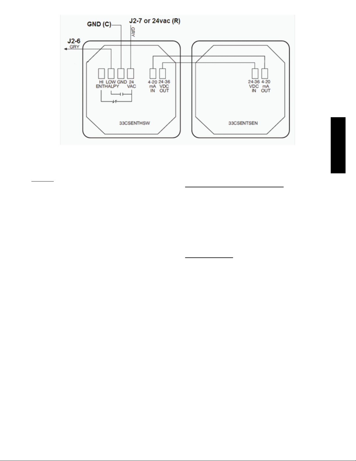
Fig. 13 -- Enthalpy Switch and Sensor Wiring
C10821
Communication Wiring--Protocols
General
Protocols are the communication languages spoken by
control devices. The main purpose of a protocol is to
communicate information in the most efficient method
possible. Different protocols exist to provide different
kinds of information for different applications. In the BAS
application, many different protocols are used, depending
on manufacturer. Protocols do not change the function of
a controller; just make the front end user different.
The RTU Open can be set to communicate on four
different protocols: BACnet, Modbus, N2, and LonWorks.
Switch 3 (SW3) on the board is used to set protocol and
baud rate. Switches 1 and 2 (SW1 and SW2) are used to
set the board’s network address. See Fig. 14 and 15 for
protocol switch settings and address switches. The 3rd
party connection to the RTU Open is through plug J19.
See Fig. 16 for wiring. Refer to the RTU Open v3
Integration Guide for more detailed information on
protocols, 3rd party wiring, and networking.
NOTE: Power must be cycled after changing the SW1--3
switch settings.
i--VuRBuilding Automation System
i--Vu is a Carrier front-end and Building Automation
System (BAS). It is a web based network system that uses
a native BACnet over MS/TP communication protocol.
The speed of the network can range from 9600 to 76,800
baud. Open controllers communicate with a proprietary
language called Linkage in i--Vu. Linkage is established
automatically and allows the flow of specific data across
Open devices. Refer to i--Vu literature for more
information on i--Vu.
BACnetRMS/TP
BACnet Master Slave/Token Passing (MS/TP) is used for
communicating BACnet over a sub--network of
BACnet--only controllers. This is the default Carrier
communications protocol. Each RTU Open module acts as
an MS/TP Master. The speed of an MS/TP network can
range from 9600 to 76.8K baud. Physical Addresses can
be set from 01 to 99.
48---50LHTCQ---01T
13
Page 14
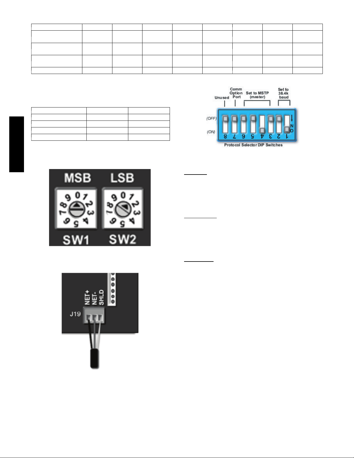
SW3 Protocol Selection
PROTOCOL DS8 DS7 DS6 DS5 DS4 DS3 DS2 DS1
BACnet MS/TP
(Master)
Modbus
(Slave)
N2
(Slave)
LonWorks Unused ON ON OFF ON OFF OFF ON
NOTE:
DS = Dip Switch
BACnet MS/TP SW3 example shown
BAUD RATE DS2 DS1
9600 OFF OFF
19,200 ON OFF
38,400 OFF ON
76,800 ON ON
Unused OFF OFF OFF ON OFF Select Baud Select Baud
Unused OFF OFF ON ON OFF Select Baud Select Baud
Unused OFF OFF OFF ON ON OFF OFF
Baud Rate Selections
Fig. 14 -- RTU Open SW3 Dip Switch Settings
48---50LHTCQ---01T
Modbus
The RTU Open module can speak the Modicon Modbus
RTU Protocol as described in the Modicon Modbus
Protocol Reference Guide, PI----MBUS----300 Rev. J. The
speed of a Modbus network can range from 9600 to 76.8K
baud. Physical Addresses can be set from 01 to 99.
Johnson N2
N2 is not a standard protocol, but one that was created by
Johnson Controls, Inc. that has been made open and
available to the public. The speed of N2 network is
limited to only 9600 baud. Physical Addresses can be set
C10815
Fig. 15 -- RTU Open Address Switches
from 01 to 99.
LonWorks
LonWorks is an open protocol that requires the use of
Echelon’s Neuron microprocessor to encode and decode
the LonWorks packets. In order to reduce the cost of
adding that hardware on every module, a separate
LonWorks Option Card (LON--OC) was designed to
connect to the RTU Open.
This accessory card is needed for LonWorks and has to be
ordered and connected using the ribbon cable to plug J15.
The RTU Open’s baud rate must be set to 38.4k to
communicate with the LonWorks Option Card. The address
switches (SW1 & SW2) are not used with LonWorks.
C07166
Fig. 16 -- Network Wiring
C10816
14
Page 15
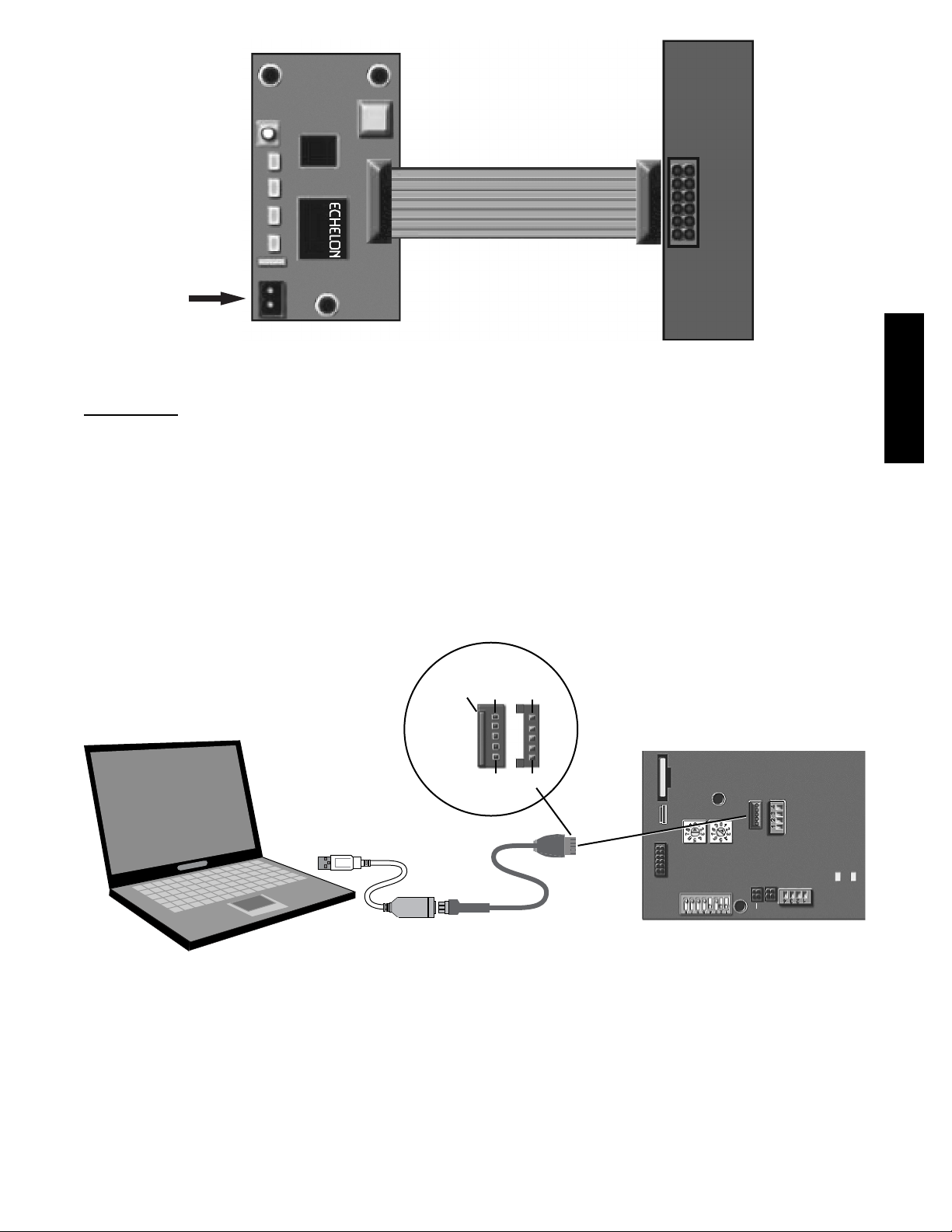
LON OC Rev.4
COMM
OPTION
Network
Net
Connector
Local Access
Wall Mounted Equipment Touch
The Equipment Touch is a wall mounted interface used to
connect to the RTU Open to access the control
information, read sensor values, and maintenance. This is
an accessory interface that does not come with the RTU
Open controller. You wire the Equipment Touch to the
RTU Open’s J13 local access port. There are 2 password
protected levels in the display (User and Admin). See the
Equipment Touch Installation and Setup Guide for more
information. See Appendix A for navigation and screen
content.
1 2
Fig. 17 -- LON--OC and LON Network Wiring
Access
Port
J15
C12750
Field Assistant
Field Assistant is a computer program included with the
purchase of the Tech Tool Kit (USB-TKIT). This is a field
Tech Tool to set-up, service, or download application
software to the RTU Open controller and includes a USB
Link Cable. The link cable connects a USB port to the J12
local access port. The Field Assistant’s menu structure is
similar and functions the same as i--Vu
P1 P1
R
. See Fig. 18.
48---50LHTCQ---01T
Connect to
computer’s
USB port
J12
P5 P5
Connect to
the Local
USB Link Kit
Access port
Fig. 18 -- PC Running Field Assistant
-
CR2032
J15
+
COMM
on
MSB LSB
SW1 SW2
OPTION
SW3
RTU Open
LOCAL
ACCESS
PORT
J12
mA
*Therm
UI-11
RNET
mA
UI-10
*Therm
J13
+12 DVC
RnetRnet+
GND
GND
GND
TXRX
J20
C14131
15
Page 16

START--UP
IMPORTANT: Follow the base unit’s start-up sequence
documented in its specific instructions. Use the base unit’s
start-up check list when performing the start-up. At the
end of this manual there is an additional RTU Open
Start-up Sheet to be completed and included with the base
unit check list.
Besides the base unit start-up, there are a few steps to take to
properly start-up the controls. RTU Open’s Service Test
function should be used to assist in the base unit start-up and
also allows verification of output operation. Controller
configuration is also part of start-up. This is especially
important when field accessories have been added to the
unit. The factory pre-configures options installed at the
factory. There may also be additional installation steps or
inspection required during the start-up process.
Additional Installation/Inspection
Inspect the field installed accessories for proper
installation, making note of which ones do or do not
require configuration changes. Inspect the RTU Open’s
Alarms for initial insight to any potential issues. See
48---50LHTCQ---01T
troubleshooting section for alarms. Inspect the SAT sensor
for relocation as intended during installation. Inspect
special wiring as directed below.
Power Exhaust Relay Power
The relay used by the RTU Open board to control power
exhaust is a dry contact which means it does not have
24vac. This 24vac must be connected to the relay to allow
it operate the power exhaust relay in the PE accessory. A
24vac source should be provided to the J11-2 pin on the
RTU Open. This can be provided by the unit’s transformer
from various sources. The “R” terminal on the unit’s
Integrated Staging Control (ISC) board (on 48/50LC
07--26 units) or the “R” terminal on the Central Terminal
Board (CTB) (on all 48/50TC(Q), 48/50HC(Q) and 04--06
48/50LC units) is a logical source.
NOTE: Factory installed power exhaust comes
pre--configured and does not require routing 24vac as
described above. This factory installed option is only
available on the following vertical air flow units:
48/50TC(Q) 17--30, 48/50HC 16--30, and 48/50LC 14--26.
Service Test
The Service Test function can be used to verify proper
operation of compressors, heating stages, indoor fan,
power exhaust fans, economizer, and dehumidification.
Use of Service Test is recommended at initial system start
up and during troubleshooting. See Appendix A for
Service Test Mode table.
Service Test mode has the following changes from normal
operation:
S Outdoor air temperature limits for cooling circuits,
economizer, and heating are ignored.
S Normal compressor time guards and other staging
delays are ignored.
S The status of Alarms (except Fire and Safety chain) is
ignored, but all alerts and alarms are still broadcasted
on the network.
Service Test can be turned ON/OFF from Field Assistant,
from the network, or from the Equipment or System
Touch. Once turned ON, other entries may be made with
the display or through the network. To turn Service Test
on, change the value of Test Mode to ON, to turn Service
Test off, change the value of Test Mode to OFF.
Service Test allows testing of each controller output.
Binary Service Test functions are on when the Default
Value is set to Enable and off when set to Disable.
The output of the Analog Service Test is controlled by
percentage (0--100%) entered into the Default Value.
It is recommended to return every Service Test variable to
Disable or 0.00 after testing each function (unless that test
variable must be active to test a subsequent function. As
in Compressor 2 Test).
All outputs return to normal when Service Test is set to
Disable. In addition, Service Test also returns to Disable
after 1 hour.
Fan Test
This point allows the board’s fan output to be manually
turned On (Enable) and Off (Disable). Other test points
that require the fan for operation will automatically turn
the fan on and this point will still show “Disable.” Fan test
can operate simultaneously with other Service Test Points.
For units equipped with variable speed fans, the fan test
will operate the unit’s fan at minimum VFD output speed.
High Speed Fan Test
Use the High Speed Fan Test to activate and deactivate
the Supply Fan (BO--1) output. Note that this output is
only applicable if Fan Control is set to Two Speed and
Unit Type is NOT equal to HP O/B Ctrl.
Compressor 1 and Compressor 2 Test
The compressor test points are used to change output
status for the individual compressors. Compressor starts
are not staggered. The fan and heating service test outputs
are reset to “Disable” for the compressor service tests.
The Indoor fan and outdoor fans are controlled normally
to maintain proper unit operation. All normal cooling
alarms and alerts are functional.
NOTE: For the LC WeatherExpert size 07--26 units, each
compressor stage can be operated independently.
Heat 1 and Heat 2 Test
The heat test points are used to change output status for
the individual heat stages, gas or electric. The fans and
cooling service test outputs are reset to “Disable” for the
heat service tests. Indoor and outdoor fans are controlled
normally to maintain proper unit operation. All normal
heating alarms and alerts are functional.
Dehumidification Test
For units with the factory Reheat option, the dehumidification relay is used to change the output status to operate the
circuits in different Reheat modes. Dehumidification relay
on by itself puts all circuits running in Hot Gas Reheat dehumidification mode; dehumidification relay on and the cooling test (compressor test relays) on puts unit and or individual circuits in subcooling dehumidification mode. The fans
and heating service test outputs are reset to “Disable” for the
dehumidification service test. Indoor and outdoor fans are
controlled normally to maintain proper unit operation. All
normal cooling/dehum alarms and alerts are functional.
16
Page 17

Power Exhaust Test
This point allows the board’s power exhaust (PE) output
to be manually turned On (Enable) and Off (Disable).
Power Exhaust test can operate simultaneously with other
Service Test Points.
Economizer Test
This point allows the board’s economizer output to be
manually controlled from 0 to 100 % Open. Economizer test
can operate simultaneously with other Service Test Points.
VFD Speed Test
This point activates the board’s 0--10vdc analog output
that controls the unit’s supply fan VFD speed.
NOTE: This output is only applicable if Fan Control is
set to Variable Speed.
NOTE: Service Test Mode does not timeout. Be sure to
turn off test mode or cycle power to the RTU to return to
normal operation.
Configuration
The RTU Open controller’s configuration points effect the
unit’s inputs and operation. Review and understand the
meaning and purpose of each configuration point before
changing it from the factory default value. Use the RTU
Open Start-up Sheet during configuration; fill in changed
values if changed from factory default. There are three main
configurations menus: SETPOINT, UNIT, and SERVICE.
Each configuration point is described below under its
according menu. See Appendix A for menu structure.
Setpoint
Occupied Heating Setpoint -- The heating setpoint the
controller maintains during the occupied period.
Range = 40 - 90_F Default = 70_F
Occupied Cooling Setpoint – The cooling setpoint the
controller maintains during the occupied period.
Range = 55 - 99_F Default = 76_F
Unoccupied Heating Setpoint – The heating setpoint the
controller maintains during the unoccupied period.
Range = 40 - 90_F Default = 55_F
Unoccupied Cooling Setpoint – The cooling setpoint the
controller maintains during the unoccupied period.
Range = 45 - 99_F Default = 90_F
Effective Heating Setpoint – The current setpoint value
heating operation will control to.
Range = 0 - 120_F
Effective Cooling Setpoint – The current setpoint value
cooling operation will control to.
Range = 0 - 120_F
Optimal Start - The earliest time prior to occupancy, at
which the Optimal Start function may begin to adjust the
effective setpoints. Setting this to 0 will disable optimal start.
Range = 0 - 4 hours Default = 4 hour
Occ Relative Humidity Setpoint – The space RH setpoint
the controller maintains during the occupied period.
Range = 0 to the Unocc RH setpoint
Default 60%
Unocc Relative Humidity Setpoint – The space RH
setpoint the controller will maintain during the
unoccupied period.
Range = 30-100% Default = 95%
DCV Max Ctrl Setpoint – The difference between indoor
and outdoor CO
ventilation damper position.
Range = 0-9999ppm Default = 650ppm
Power Exhaust Setpoint –Usedtodeterminewhenthe
power exhaust operation will begin. This setpoint is based
on the maximum fan speed. When the economizer
position opens above this point, power exhaust operation
will begin and when the damper position falls 5% below
this point, the power exhaust will shutdown.
Range = 20-90% Default = 50%
NOTE: This setpoint is automatically adjusted if the Fan
Type is set to Variable Speed or 2--Speed in order to
maintain proper building pressure. The actual calculated
value, Calculated PE Setpoint, is shown in
MAINTENANCE.
NOTE: This point is only used when Continuous
Occupied Exhaust = NO
level which results in maximum
2
Unit
Fan Mode – Sets the operation of the indoor fan when not
in cooling or heating mode. Refer to fan operation for
details on each operation.
Range = Auto, Continuous, or Always On
Default = Continuous
Power Fail Restart Delay -- Sets how long the controller
delays normal operation after the power is restored.
Typically used to prevent excessive demand when
recovering from a power failure
Range = 0 - 30 sec Default = 5 sec
Fan Off Delay – Time delay in which the fan will
continue run after being commanded off.
Range = 10 -300 sec Default = 90 sec
Minimum Cooling SAT – The supply air temperature
must remain above this value to allow cooling with the
economizer and/or compressors. There is 5_Fplusand
minus deadband to this point. If the SAT falls below this
value during cooling a compressor stage will be removed
and/or the economizer will return to minimum position.
Range = 45 - 75_F Default = 50_F
Maximum Heating SAT – The supply air temperature must
remain below this value to allow heating. There is 5_Fplus
and minus deadband to this point. If the SAT falls below this
value during heating the heat stages will begin to decrease
until the SAT has dropped below this value.
Range = 85 - 150_F Default = 120_F
Vent Dmpr Pos / DCV Min Pos – Minimum damper
position for ventilation during the occupied period when
the fan is operating at full speed.
Range = 0 -- 100% open Default = 20% open
Economizer Purge Min Pos – The damper position used
during the Pre--Occupancy Purge cycle prior to occupancy
when Pre--Occupancy purge is active
Range = 0 -- 100% open Default = 40% open
Low Fan Econ Min Pos – The minimum damper position
used for ventilation during the occupied period when the
fan is operating at it’s lowest speed.
Range = 0 -- 100% open Default = 33% open
NOTE: This setpoint is only applicable if the Fan Type is
set to Variable Speed or 2--Speed.
48---50LHTCQ---01T
17
Page 18

DCV Max Vent Damper Pos – This is the greatest
position the economizer can open to while trying to
control the indoor air quality levels
Range = 0 -- 75% open Default = 50% open
Supply Fan Service Alarm Timer – The timer set for the
Supply Fan Runtime Alarm. After the number of hours set
on this point is exceeded the corresponding alarm will be
generated, and must be manually cleared in the maintenance
menu after the maintenance has been completed. The timer
will then begin counting its runtime again for the next due
maintenance.
Range = 0 to 9999 hr Default = 600 hr
NOTE: If set to 0 hr this setpoint is disabled and its alarm
will never be generated.
Comp 1 Service Alarm Timer – The timer set for the
Compressor 1 Runtime Alarm. After the number of hours
set on this point is exceeded the corresponding alarm will
be generated, and must be manually cleared in the
maintenance menu after the maintenance has been
completed. The timer will then begin counting its runtime
again for the next due maintenance.
48---50LHTCQ---01T
NOTE: Default = 0 hours, if set = 0 hr this point is
Range = 0 to 9999 hr Default = 0 hr
disabled and its alarm will never be generated.
Comp 2 Service Alarm Timer – The timer set for the
Compressor 2 Runtime Alarm. After the number of hours
set on this point is exceeded the corresponding alarm will
be generated, and must be manually cleared in the
maintenance menu after the maintenance has been
completed. The timer will then begin counting its runtime
again for the next due maintenance.
Range = 0 to 9999 hr Default = 0 hr
NOTE: Default = 0 hours, if set = 0 hr this point is
disabled and its alarm will never be generated.
Filter Service Alarm Timer – The timer set for the Dirty
Filter Alarm. After the number of hours set on this point is
exceeded the corresponding alarm will be generated, and
must be manually cleared in the maintenance menu after the
maintenance has been completed. The timer will then begin
counting its runtime again for the next due maintenance.
Range = 0 to 9999 hr Default = 600 hr
NOTE: Default = 600 hours, if set = 0 hr this point is
disabled and its alarm will never be generated.
Pushbutton Override – Set to enable or disable the pushbutton override function of the locally installed space sensor.
Range = Disable/Enable Default = Enable
Door Alarm Delay -- Determines the amount of delay
before a door alarm is generated.
Range = 0 to 3600 seconds Default = 60 seconds
Setpoint Adjustment – Set to enable or disable the setpoint
adjustment function of the locally installed space sensor.
Range = Disable/Enable Default = Enable
Setpoint Adjustment Range -- Sets the slider range of a
space sensor (with built in function). The slider is used to
offset the control setpoint
Range = 0 to 5_F Default = 5_F
Cooling Lockout Temperature -- This defines the
minimum outdoor air temperature that cooling mode can
be enabled and run. If the OAT falls below this number
during cooling the compressors will be de-energized
Range = --65 - 80_F Default = 45_F
Economizer High OAT Lockout Temp – If the outdoor
air temperature rises above this value, economizer cooling
will be disabled and dampers will return and stay at
minimum position.
Range = 55 - 80_F Default = 75_F
Heating Lockout Temperature – This defines the
maximum outdoor air temperature that heating mode can
be enabled and run. If the OAT rises above this number
during heating the heat stages will be de-energized.
Range = 35 -- 150_F Default = 65_
F
Pre--Occupancy Purge -- Enables or disables the use of a
purge cycle immediately prior to the start of a scheduled
occupied period.
Range = Enable/Disable Default = Disable
Purge Time -- The maximum amount of time used for a
pre--occupancy purge.
Range = 0 to 240 minutes Default = 60 minutes
Unocc Free Cool Enable – Set to enable or disable the
economizer for night time free cooling (NTFC) operation.
Range = Disable/Enable Default = Disable
Setpoint Separation – Sets the minimum separation gap
in which setpoints can be set.
Range = 2 - 10_F Default = 5_F
Occupancy Source – Tells the controller which method of
occupancy control to use in determining occupancy of the
rooftop. Refer to Occupancy in the operation section for
detail on each specific operation function.
Range = Always Occupied, BACnet Schedule,
BAS On/Off, or Remote Occ Input
Default =Always Occupied
Inputs
Input 1 Function – This input is an analog input and can
be configured to be one of four different inputs: No
Sensor, IAQ Sensor, OAQ Sensor, or Space RH Sensor.
Input 1 is wired to pin J4--4,5,6.
Default = No Sensor
Input 2 Function – This input is an analog input and can
be configured to be one of four different inputs: No
Sensor, IAQ Sensor, OAQ Sensor, or Space RH Sensor.
Input 2 is wired to pin J4--1,2,3.
Software Default = No Sensor
Factory Default = IAQ Sensor with factory
installed CO
NOTE: For Inputs 1 & 2, if using Carrier air quality
sensors do not use 24Vdc from RTU Open board. External
24Vdc power supply required.
Input 3 -- This input is a discrete input and can be
configured to be one of six different functions: No
Function, Compressor Safety, Fan Status, Filter Status,
Remote Occupancy, or Door Contact. This input can also
be configured to be either a Normally Open (N/O) or a
Normally Closed (N/C) switch. Input 3 is factory wired to
pin J1-2. Field accessories can be wired to its parallel pin
J5-5.
Factory Default = Compressor Safety and N/O
sensor
2
18
Page 19

Input 5 -- This input is a discrete input and can be
configured to be one of six different functions: No Function,
Fire Shutdown, Fan Status, Filter Status, Remote Occupancy,
or Door Contact. This input can also be configured to be
either a Normally Open (N/O) or a Normally Closed (N/C)
switch. Input 5 is factory wired to pin J1-10. Field
accessories can be wired to its parallel pin J5-3.
Software Default = Fire Shutdown and N/C
Factory Default = Fire Shutdown and N/O
Input 8 -- This input is a discrete input and can be
configured to be one of six different functions: No
Function, Enthalpy Switch, Fan Status, Filter Status,
Remote Occupancy, or Door Contact. This input can also
be configured to be either a Normally Open (N/O) or a
Normally Closed (N/C) switch. Input 8 is factory wired to
pin J2-6. Field accessories can be wired to its parallel pin
J5-1.
Software Default= Enthalpy Switch and N/O
Factory Default = No Function and N/O without
factory installed enthalpy sensor
Input 9 -- This input is a discrete input and can be
configured to be one of seven different functions: No
Function, Humidistat, Fan Status, Filter Status, Remote
Occupancy, Door Contact, or IGC Override. This input
can also be configured to be either a Normally Open
(N/O) or a Normally Closed (N/C) switch. Input 9 is
factory and field wired to pin J5-7.
Factory Default = Humidistat and N/O
NOTE: For 48LC 07--26 Units (gas heat units) this decision
is automatically set to IGC Override and is factory wired.
Space Sensor Type – This tells the controller what type
of space sensor is installed to run the unit. The four types
that can be used are: a standard 10k Type II thermistor
(T55), sensor with a setpoint offset slider bar (T56), or a
communicating sensor (SPT Sensor) and, ZS Sensor.
Range =T55, T56 (Use for T59), SPT Sensor,
or ZS Sensor
Default = T55
ZS Sensor Type -- The type of local space temperature
sensor.
Range =ZS Base, ZS Plus, ZS Pro
Default = None
T5x Override Duration – Sets the override time duration
the unit will change from unoccupied to occupied when
the override button is pushed on the space sensor.
Range = 0-24 hours Default = 1 hour
Rnet Port -- input for communicating sensor or
Equipment Touch Terminal J13 -- 1, 2, 3, 4
Range = SPT Sensor, ZS Sensor, or
Equipment Touch
Default= None
Service Configuration
Unit Type – This tells the control what type of unit it is
controlling. Heat/Cool refers to gas and electric heat units.
LC WeatherExpert refers to a special 3 stage/2 compressor
unit. HP O/B Ctrl refers to a heat pump unit which
requires reversing valve control. HP Y1/W1 Ctrl refers to
a heat pump unit whose reversing valve is built in to the
cooling or heating call. This decision is factory configured
for the specific unit type as supplied.
NOTE: When unit type is set to LC WeatherExpert other
configuration settings in the Service Configuration menu
will become hidden from user’s view. The configurations
that become hidden include Compressor Stages, Face Split
Coil, Fan Control.
Compressor Stages – This refers to the number of
mechanical cooling stages available on a specific unit. For
LC size 07--26 units this setting is “Three Stage” and is
not a visible menu configuration.
Factory Default = “Three Stage” for LC size
07--26 units
Economizer Exists – This indicates if there is an
economizer installed on the unit.
Factory Default = NO if no economizer, or YES if
there is an economizer installed
Fan Control -- This refers to the type of fan control for the
given unit. If Unit Type is selected to LC WeatherExpert,
then this is set to Variable Speed, and is not a visible menu
configuration.
Factory Default = Variable Speed for LC size
07--26 units.
VFD Input -- Defines the electrical control signal used by
the VFD’s input. Applies to Variable Speed fan control only
(LC size 07--26 units by default).
Range = 2--10VDC or 0--10VDC
Factory Default = 2--10 VDC
Max VFD Output --ThemaximumVFDsignalRTUOpen
supplies to the VFD as a percentage of its range. The
balancer can set this to adjust the unit’s maximum airflow.
Applies to Variable Speed fan control. (LC size 07--26 units
by default)
Range = 33--100% Default = 100%
Min VFD Output -- The minimum VFD signal RTU Open
supplies to the VFD as a percentage of its range. The
balancer can set this to adjust the unit’s minimum airflow.
Applies to Variable Speed fan control only (LC size 07--26
by default)
Range = 33--100% Default = 40%
Dehum Min VFD Output -- The minimum output signal
supplied by RTU Open during dehumidification as a
percentage of its range. Applies to Variable Speed fan
control only (LC size 07--26 by default)
Range = 50--100% Default = 100%
Stage 1 SAT Setpoint -- The VFD Supply Air Setpoint
during stage 1 cooling. Must be at least 4_F greater than
Minimum Cooling SAT parameter
Range = 45 -- 75_F Default = 57_F
Stage 2 SAT Setpoint -- The VFD Supply Air Setpoint
during stage 2 cooling. Must be at least 4_F greater than
Minimum Cooling SAT parameter
Range = 45 -- 75_F Default = 57_F
Stage 3 SAT Setpoint -- The VFD Supply Air Setpoint
during stage 3 cooling. Must be at least 4_F greater than
Minimum Cooling SAT parameter
Range = 45 -- 75_F Default = 56_F
Heat Type – Indicates the type of heat which is installed in
the unit. Electric is any unit without gas and a Gas unit is
one which requires gas input for heating.
Factory Default = Gas for gas units and Electric for
all other units (cooling only units and heat pumps)
48---50LHTCQ---01T
19
Page 20

Number of Heat Stages – Indicates how many heat
stages are available for use. See configuration in
Appendix A for details on specific unit configuration.
Factory Default =1 for single heat stage units
2 for dual stage units
0 for cooling only units
Continuous Occupied Exhaust – This point tells the
controller when to run the power exhaust if equipped on
the unit.
If set to YES, the power exhaust will be on all the time
when in occupied mode and will be off when in
unoccupied mode. If set to NO the power exhaust will be
controlled by the Power Exhaust Setpoint.
Default = NO
RH Control -- Enables dehumidification control if an RH
sensor is available and the unit has the Humidi--MiZer
dehumidification option installed.
Range =Disable/Enable
Default = Disable
(Enabled with Humidi--MiZer option)
DCV Control -- Enables demand controlled ventilation
(DCV)ifvalidCO
48---50LHTCQ---01T
has an economizer installed.
sensor value is available and the unit
2
Range = Disable/Enable
Default = Disable
System Space Temperature -- The network space
temperature value that the controller is using for control
(if applicable).
Range = N/A Default = --999.0_F
System Space RH -- The network relative humidity value
that the controller is using for control (if applicable)
Range = N/A Default = --999.0%
System Space AQ -- The network indoor air quality (CO
value that the controller is using for control (if applicable)
Range = N/A Default = --999.0 PPM
System Cool Demand Level -- The system cool demand
level being received over the network
Range = N/A Default = 0--3
System Heat Demand Level -- The system heat demand
level being received over the network
Range = N/A Default = --0--3
System Outdoor Air Temperature -- Allows the outdoor
air temperature value to be network readable when
enabled. Requires RTU Open to be equipped with an
outdoor air temperature sensor
Range = N/A Default = --999.0_F
System Outdoor AQ -- Allows network readable value of
OAQ for calculation during differential OAQ CO
and IAQ CO
levels to drive the IAQ control
2
Range = N/A Default = --999.0 PPM
System Fire / Smoke -- Allows network readable fire/smoke
signal to invoke shutdown action in the RTU
Range = N/A Default = OFF
Indoor CO
value when the board reads 4 mA at input 1 or 2.
CO
2
Sensor Value @ Min mA – Sets the indoor
2
Range = 0 to 9999 ppm Default = 0 ppm
Indoor CO
value when the board reads 20 mA at input 1 or 2.
CO
2
Sensor Value @ Max mA – Sets the indoor
2
Range = 0 to 9999 ppm Default = 2000 ppm
levels
2
Outdoor CO
value when the board reads 4 mA at input 1 or 2.
CO
2
Sensor Value @ Min mA – Sets the outdoor
2
Range = 0 to 9999 ppm Default = 0 ppm
Outdoor CO2Sensor Value @ Max mA – Sets the outdoor
value when the board reads 20 mA at input 1 or 2.
CO
2
Range = 0 to 9999 ppm Default = 2000 ppm
NOTE: The indoor and outdoor min and max mA setting
are used to set the linear curve of mA vs. PPM.
OPERATION
The RTU Open will control the compressors, economizer
and heating outputs based on its space temperature input
and setpoints. It can also be controlled by a building
R
IAQ
2
Open
control system or zoning system. An optional CO
R
sensor mounted in the space can influence the economizer
minimum position. The RTU Open has a hardware clock
that can allow scheduling for stand-alone operation. The
RTU Open’s default is to control to occupied setpoints all
the time, until a type of occupancy control is set. The
following sections describe the operation for the functions
of the RTU Open.
Occupancy
Occupancy is the fundamental overall control of
equipment. The unit can be in one of two states: Occupied
or Unoccupied. These are usually referred to as periods
because they represent periods of any given day. Before
RTU Open can operate specific functions of the
equipment it is installed on, occupancy must be
determined. There are four different ways RTU Open can
determine occupancy. These are described below and
selected by the configuration point Occupancy Source.
Always Occupied (Default)
)
2
The unit will not determine occupancy and continuously
run in the occupied state or period. RTU Open ships from
the factory with this setting to allow immediate operation.
BACnetRSchedule
When Occupancy Source is set to BACnet Schedule, RTU
Open will use a schedule to change occupancy based upon
a day of week and a time period. Local time and date
should be set in the RTU Open for this function to operate
properly. This function applies if setting a local schedule
in the RTU Open or if applying the unit to an i--Vu
Building Automation System or an Open zoning system.
An Open network schedule can override a local schedule
within the unit. A space sensor push button override is
only available when running a local or Open schedule.
The push button will override an unoccupied period to
occupied for the specified time duration.
BAS On/Off
When Occupancy Source is set to BAS On/Off, RTU
Open follows occupancy based on an On/Off command to
the BAS ON/OFF software point. An on command sets
the occupancy to occupied, and an off command sets it to
unoccupied. The Building Automation System can be
speaking BACnet, Modbus, N2, or LON and is writing to
the BAS On/Off point in the open protocol point map.
Remote Occ Input
When Occupancy Source is set to Remote Occ Input, RTU
Open follows occupancy based on the remote occupancy
20
Page 21

switch input. Inputs 3, 5, 8, and 9 on plug J5 can be
hard-wired to command the unit’s occupancy. The
Occupancy Contact point show the status as on or off, on
is occupied and off is unoccupied.
Indoor (Supply) Fan
The indoor fan can be configured to operate in three
different manors. The configuration point Fan Mode
determines how the fan will run. The fan will always be
disabled if a fire shutdown or safety chain alarm is active.
A valid space temperature and supply air temperature
must be available for the fan to operate. There is a unit
start delay in effect when the unit is transitioning from
unoccupied to occupied. The following describes specific
fan operation based on the Fan Mode configuration value.
Auto
When Fan Mode is set to Auto, RTU Open will cycle the
fan on and off based on the demand for heating, cooling,
and dehumidification. There is a configurable fan off
delay that is upheld before shutting the fan off after
conditioning has ended.
Continuous
When Fan Mode is set to Continuous, RTU Open will
cycle the fan based on occupancy. The fan will run
continuously whenever the unit is occupied and operate in
the auto mode during the unoccupied period.
Always On
When Fan Mode is set to Always On, RTU Open will run
the fan all the time regardless of occupancy or demand.
Fan Off Delay
A Fan Off Delay allows the supply fan to continue
operating after heating or cooling stops. If the following
alarms are active, the fan turns off immediately, regardless
of the occupancy state or demand:
S Fire Shutdown
S Safety Chain
S Supply Air Temp Sensor alarm
The RTU Open does not include smoke--control
functions such as smoke--purge, zone--pressurization, or
smoke--ventilation.
Indoor (Supply) Fan Status
The RTU Open has an optional Supply Fan Status input to
provide proof of airflow. If this is enabled, the point will
look for a contact change whenever the Supply Fan Relay
is on. If it is not enabled then it will always be the same
state as the Supply Fan Relay. The cooling, economizer,
heating, dehumidification, CO
routines will use this input point for fan status.
and power exhaust
2
Cooling
The compressor outputs are controlled by the Cooling
Control PID Loop and Cooling Stages Capacity algorithm.
They will be used to calculate the desired number of stages
needed to satisfy the space by comparing the Space
Temperature (SPT) to the Occupied Cool Setpoint plus the
T56 slider offset when occupied and the Unoccupied Cool
Setpoint (UCSP) plus the T56 slider offset, if unoccupied.
The economizer, if available, will be used for cooling in
addition to the compressors. The following conditions must
be true in order for this algorithm to run:
S Outdoor Air Temperature, if valid, is greater than the
Cooling Lockout Temperature setpoint.
S Indoor Fan is ON.
S Heat mode has not been active for 5 minutes.
S If occupied and the SPT > (occupied cool setpoint plus
the T56 slider offset).
S Space Temperature and supply air temperature values
are valid.
S If it is unoccupied and the SPT > (unoccupied cool
setpoint plus the T56 slider offset).
S Economizer is unavailable, or if the Economizer is active,
mechanical cooling is available if the economizer is open
> 90% for at least 7.5 minutes, the SAT > [Minimum
Cooling SAT + 5_F(2.7_C)] and SPT > [Effective
Cooling Setpoint + 0.5_F (0.27_C)].
If all of the above conditions are met, the controller uses a
PID logic loop to energize or de--energize compressors to
satisfy the cooling demand.
There is a fixed 3--minute minimum on time and a
5--minute off time for each compressor output.
Any time the compressors are running the RTU Open will
stage down the compressors if the SAT becomes less than
the cooling low supply air setpoint. After a compressor is
staged off, it may be started again after a normal
time--guard period and the supply air temperature has
increased above the low supply air setpoint.
S Cooling – Without humidity control [RH Control =
Disable] or an economizer [Economizer Exists = No],
the operation of the unit is as follows:
If OAT > Cooling Lockout Temperature (45_Fdef)and
SPT > cooling setpoint, then a PID will calculate the
required number of compressor cooling stages required
to satisfy the present space load conditions. After the
minimum compressor off time has expired, then the first
compressor stage will be started. The actual number of
active compressor stages [Active Compressor Stages] is
displayed in the maintenance section.
As the compressor stage(s) operate, the controller monitors
the supply air temperature and compares the measured
value to the configured supply air temperature setpoint
[Stage 1 SAT Stpt if Active Compressor Stages = 1, see
the table below].
The fan will begin to operate (or currently be operating)
at the configured minimum fan speed [Min VFD
Output]. If the measured SAT falls below this setpoint, a
PID will calculate the required VFD output to increase
the fan speed to obtain the configured Stage “X” SAT
Stpt depending on the actual number of the operating
stage (1--3). The fan speed can increase as required but
not greater than the configured maximum speed [Max
VFD Output].
Active Compressor Stages Controlling SAT setpoint
=1 Stage 1 SAT Stpt
=2 Stage 2 SAT Stpt
=3 Stage 3 SAT Stpt
48---50LHTCQ---01T
21
Page 22

Supply Fan
The RTU Open supply fan may be configured for 1 of 3
Fan Control modes:
S Single -- The fan operates at one speed only and
provides on/off operation
S Two Speed -- The fan operates at 1 of 2 speeds depending
on the mode of operation and load conditions. During fan
only or single stage cooling, the fan operates at low speed.
During heating, dehumidification, second stage cooling, or
if maximum economizer operation is required, the fan
operates at high speed. This control mode is used with
48/50TC(Q), 48/50HC(Q) and size 04--06 48/50LC units
when Staged Air Volume (SAV) option is provided.
S Variable Speed -- The fan operates at a variable speed to
meet the load conditions and SAT safety requirements to
provide maximum energy savings by minimizing fan
horsepower consumption. Fan speed is NOT controlled by
static pressure. This setting is default for LC
WeatherExpert size 07--26 units and when WeatherExpert
48---50LHTCQ---01T
is selected under Unit Type configuration.
The RTU Open supply fan may be configured for 1 of 3
Fan Modes:
S Auto -- The fan cycles on/off in conjunction with
heating or cooling.
S Continuous -- The fan runs continuously during
occupancy and intermittently during unoccupied
periods with heating and cooling.
S Always On -- The fan runs continuously regardless of
occupancy or calls for heating and cooling.
Occupancy can be determined by Linkage, BACnet
schedules, BAS schedules, or in response to a remote
occupancy switch.
A Fan Off Delay allows the supply fan to continue
operating after heating or cooling stops.
If the following alarms are active, the fan turns off
immediately, regardless of the occupancy state or demand:
S Fire Shutdown
S Safety chain
S SAT sensor alarm
S SPT sensor alarms
The RTU Open does not include smoke--control functions
such as a smoke--purge, zone--pressurization, or smoke--ventilation. Each of these modes require a field--designed circuit
to operate the following by local fine codes:
S RTU supply fan
S RTU economizer
S RTU power exhaust
The RTU Open many be configured to accept a Supply
Fan Status input to provide proof the supply fan is
operating. When enabled, a loss or lack of fan status will
stop heating and cooling operation.
A supply Fan Alarm Service Timer function is available
to track the number of supply fan run hours and generate
an alarm when the accumulated runtime exceeds the set
threshold.
Economizer
The Economizer dampers are used to provide free cooling
when the outside conditions are suitable and Indoor Air
Quality, if optional CO
The following conditions must be true for economizer
operation:
S Indoor Fan is on.
S Enthalpy is Low if the Enthalpy input is enabled.
S SAT reading is available.
S OAT reading is available.
S SPT reading is available.
S OAT <= High OAT economizer lockout configuration
(default = 75).
S OAT <= SPT
If any of the mentioned conditions are not true, the
economizer will be set to its configured minimum position.
If the RTU Open is configured for VFD or 2--speed fan,
and the fan is on or at the highest speed, or if the unit is
configured for single--speed fan, then the economizer will
use the Vent Dmpr Pos/DCV Min Pos setpoint as the
minimum economizer position when occupied. If the unit
is configured for VFD or 2--speed fan, and the fan is on or
at the lowest speed, the economizer will use the Low Fan
Econ Min Pos.
NOTE: For LC WeatherExpert units or any unit with
Variable Speed fan control, the RTU Open will determine
the required minimum economizer position (Calculated
Min Econ Pos) based on the fan’s actual operation speed.
The minimum damper position can be overridden by the
IAQ routine described later in this section.
If the above conditions are true, the Economizer control
will calculate a damper position starting with a minimum
vent position and based on current space temperature and
a setpoint that is one degree less than the effective cool
setpoint. If the SAT drops below the cooling low supply
air setpoint (+ 5_F), the economizer will close as required
but not to less than the to minimum position. The
Calculated Min Econ Pos used for control is displayed in
the Maintenance section.
RTU Open provides Fault Diagnostic and Detection
(FDD) for economizer operation in compliance with
California Title 24. The FDD logic will detect an
economizer that fails to close, fails to open, stuck fully
open, and fails to fully open. Each condition will cause an
Economizer Operation alarm to occur and the specific
condition will be displayed.
sensor is installed.
2
Enthalpy Control
You may use an enthalpy switch to indicate the suitability of
outdoor air for economizer cooling. You can use either an
outdoor air or differential enthalpy switch. A differential
enthalpy switch has a sensing device in both the outdoor and
return air streams. A differential enthalpy switch indicates
when outside air is more suitable to be used than the return
air and is available for economizer cooling. If no enthalpy
switch is configured, a network point (Object Name: oae) is
available. This point is displayed in the i--Vu application and
Equipment Touch as Enthalpy (BACnet).
22
Page 23

The sequence of operation for economizer cooling is the
same with or without an enthalpy switch, except that an
enthalpy switch imposes one more validation on the
suitability of outside air for economizer cooling. An
Enthalpy Status that is High disables the economizer and the
outside air damper goes to its minimum position. An
Enthalpy Status that is Low enables the economizer if a call
for cooling exists and the remaining preconditions are met.
Space Air Quality
Space Air Quality (AQ) is controlled on rooftop
equipment using the economizer. The Space AQ sequence
utilizes an air quality (CO2) sensor to monitor conditions
within the occupied space. A CO
terminated at the RTU Open, or a subordinate zone
controller, when part of a zoned system.
An outdoor air quality sensor may also be installed and
terminated at the RTU Open, but is not required. When an
outdoor air quality sensor is not installed, the algorithm
uses 400ppm as the fixed outdoor air CO
The following conditions must be true for the Space AQ
algorithm to operate:
S The system is occupied
S The supply fan has been operating for at least 30 seconds
S The Space AQ sensor has a valid reading
As the air quality in the space decreases (Space AQ CO2
value increases), the minimum position of the economizer
increases, allowing more outdoor air to enter the space.
The amount of increase depends on the relationship
between the Space AQ level and the DCV Max Ctrl
Setpoint.
The Space AQ algorithm calculates a minimum position
value using a PID loop. The CO2 minimum damper position
is then compared against the Vent Dmpr Pos / DCV Min Pos
setpoint and the greatest value becomes the minimum
damper position utilized for the economizer. When the
minimum economizer position is being reset by the Space
AQ algorithm, the System Mode displays IAQ Override.
The maximum amount the economizer may be opened to
outdoor air by the Space AQ algorithm is limited by the
DCV Max Vent Damper Pos, which is adjustable between
10 and 75%.
sensor may be
2
level.
2
Power Exhaust
RTU Open may enable and disable an exhaust fan based
on either the controller’s occupancy or its economizer
damper position. If configured for continuous occupied
operation, it will be energized whenever the controller is
in the occupied mode and disabled when in the
unoccupied mode. If configured for damper position
control, it will be energized whenever the economizer
exceeds the power exhaust setpoint and disabled when the
economizer drops below the setpoint by a fixed hysteresis
of 10%. If the Fan Control is set to Two Speed or Variable
Speed, the Power Exhaust Setpoint is automatically
adjusted based on the fan’s air delivery. The Calculated
PE Setpoint used for control is displayed in the
Maintenance section.
Pre--Occupancy Purge
Pre--Occupancy Purge allow the rooftop equipment with
an economizer damper to utilize outdoor air to purge the
space of contaminates just prior to the beginning of the
occupied period.
The following conditions must be true for pre--occupancy
purge to operate:
S Pre--Occupancy Purge set to Enable
S Economizer Exists set to Yes
S A local time schedule is configured
S The local time schedule is currently unoccupied and the
remaining time is less than the configured Purge Time
When the RTU Open schedule is unoccupied and the
remaining unoccupied time is less than the purge time, the
supply fan starts. The economizer damper opens to the
configured Economizer Purge Min Pos. The RTU Open
continues to operate in this mode until the occupied start
time is reached. The Pre--Occ Purge state is displayed in
the Maintenance section.
Heating
The heat outputs are controlled by the Heating Control
PID Loop and Heating Stages Capacity algorithm. They
will be used to calculate the desired number of stages
needed to satisfy the space by comparing the SPT to the
Occupied Heat Setpoint the T56 slider offset when
occupied and the Unoccupied Heat Setpoint plus the T56
slider offset if unoccupied. The following conditions must
be true in order for this algorithm to run:
S Indoor Fan is ON for any unit with electric heat.
S Cool mode has not been active for 5 minutes.
S If occupied and SPT <(occupied heat setpoint plus T56
slider offset)
S SPT and supply air temperature values are available
S If it is unoccupied and the SPT < (unoccupied heat
setpoint plus T56 slider offset).
S OAT < High OAT lockout temperature.
If all of the above conditions are met, the controller uses a
PID logic loop to energize or de--energize heat outputs to
satisfy the heat demand. If the SAT begins to exceed the
high supply air setpoint, a ramping function will cause the
Heat Stages Capacity algorithm to decrease the number of
stages until the SAT has dropped below the setpoint. There
is a fixed one minute minimum on time and a one minute
off time for each heat output. There is a 10 minute minimum
stage up delay if the heat demand is 3_F,anda2minute
minimum stage up delay if heat demand is > 3_F.
Indoor Air Quality
If the optional indoor air quality sensor is installed, the
RTU Open will maintain indoor air quality within the
space at the user configured differential set point. The set
point is the difference between the indoor air quality and
an optional outdoor air quality sensor. If the outdoor air
quality is not present then a fixed value of 400ppm is
used. The following conditions must be true in order for
this algorithm to run:
S The mode is occupied.
S Indoor Fan is ON.
S Indoor Air Quality is a valid reading.
As air quality within the space decreases, the minimum
position of the economizer damper will be increased thus
48---50LHTCQ---01T
23
Page 24

allowing more outdoor air into the space depending on the
relationship of the indoor air quality to the differential
setpoint. If all the above conditions are true, the IAQ
algorithm will run and calculates an IAQ minimum
position value using a PID loop. The IAQ minimum
damper position is then compared against the user
configured economizer minimum position and the greatest
value becomes the final minimum damper position of the
economizer output.
If the IAQ minimum position calculated by the control is
greater than the DCV Max Vent Damper Pos configured,
then it will be clamped to the configured value.
Dehumidification
The RTU Open will provide occupied and unoccupied
dehumidification only on units that are equipped with the
Humidi--MiZer
requires a space relative humidity sensor or a humidistat
for control. The space relative humidity senor can be
installed and configured as one of the two analog input
channels (inputs 1 or 2 on J4), or a humidistat can be
installed and configured as switch input 9 on J5 (except on
units configured as LC WeatherExpert with gas heat).
48---50LHTCQ---01T
When using a relative humidity sensor to control
dehumidification, occupied or unoccupied dehumidification
setpoints are use accordingly. When using a humidistat,
setpoints are not used and the dehumidification call comes
when the humidistat indicates high humidity.
When the indoor relative humidity becomes greater than the
dehumidification setpoint (or switches from low to high), a
demand for dehumidification demand is identified.
Compressor state is monitored and time guards are honored.
If a compressor was just turned off prior to the dehum call
the dehumidification output will be delayed the 5 minute
minimum off time of the compressor. When ok to
dehumidify, the dehumidification output (J11--7, 8) will be
energized. This will bring on the supply fan (at high fan
speed if Fan Control is set to “Two Speed” or “Variable
Speed”), all compressors, and the dehumidification relay
placing the unit in Hot Gas Reheat dehumidification mode.
If dehumidification is called for during cooling or cooling is
called for during dehumidification, the unit will run in
Subcooling dehumidification mode. Individual unit circuits
can be in different dehumidification modes based on the
demand. Refer to the base units operation for additional
information.
NOTE: There is a fixed 5% hysteresis that the indoor
relative humidity must drop below the active setpoint to
end the dehumidification mode and de--energize the
dehumidification output. The output will also de--energize
if the fan relay is de--energized.
R
option from the factory. This function
Demand Limit
If the RTU Open receives a level 1 (one degree offset), 2
(two degree offset), or a 3 (4 degree offset) to the BACnet
demand limit variable, the controller will outwardly expand
the heating and cooling setpoints by the configured demand
limit setpoint value and remain in effect until the BACnet
demand limit variable receives a 0 value.
Unoccupied Free Cooling
When the unit is equipped with an economizer, the control
can run a night time free cooling (NTFC) mode called
Unocc Free Cooling. In this mode the damper is utilized
to bring in outdoor air for free cooling during unoccupied
periods. The following conditions must be true for
unoccupied free cooling to operate:
S Unocc Free Cool Enable set to Enable
S The system is unoccupied
S The outside air temperature is below the Economizer
High OAT Lockout Temp
S The outside air temperature is less than the space
temperature
S Enthalpy (if enabled) is Low
When the RTU Open schedule is unoccupied and the
space temperature rises at least 1 degree above the
Occupied Cooling Setpoint, the supply fan starts. The
economizer damper opens as necessary to cool the space.
The RTU Open continues to operate in this mode until the
space is satisfied or the outside air conditions are no
longer suitable for free cooling.
Optimal Start
The RTU Open may utilize either of two different optimal
start types. Temperature Compensated start is designed
specifically for LC units in order to minimize fan
operation. Temperature Compensated Start changes the
setpoint from the unoccupied setpoint directly to the
Occupied setpoints at a calculated time prior to occupancy
in order to achieve the occupied setpoint at the scheduled
occupied time. Learning Adaptive Start adjusts the
effective setpoints to achieve the occupied setpoints by
the time scheduled occupancy begins. The Learning
Adaptive algorithm works by moving the unoccupied
setpoints toward the occupied setpoints. The rate at which
the setpoints move is based on the outside air temperature,
design temperatures, and capacities. The Optimal Start
recovery period may begin as early as 4 hours prior to
occupancy. To disable Optimal Start, set the optimal start
type to None. The following conditions must be true for
optimal start to operate:
S Under SETPOINT, Optimal Start Value must be set
greater than zero
S The Optimal Start type must not be None
S The system is unoccupied
S The RTU Open has a valid outside air temperature
S The RTU Open is running occupancy based on a local
occupancy schedule, where next time occupied is known.
Fire Shutdown
Fire Shutdown may be configured on Binary Input 5. A
typical application involves a smoke detector or fire
shutdown contact, which, when active, immediately shuts
down equipment operation.
Compressor Safety
Compressor Safety may be configured on Binary Input 3.
This feedback can be provided by a Compressor
Lock--Out (CLO) device or current switch when field
installed. A Compressor Safety Alarm indicates that the
equipment requires attention. Cooling, heating, and supply
fan outputs are not interrupted. Normal operation resumes
when the compressor safety circuit is de--energized.
24
Page 25

Fan Status
Fan Status may be configured on any unused binary input
channel. A typical application would be an airflow switch,
current sensing relay, or other device that provides a supply
fan running verification. Enabling this function displays the
supply fan’s status on the equipment graphic. If the
controller loses fan status during operation, heating and
cooling are disabled, the economizer damper (if available) is
closed, and an alarm for loss of status is indicated. If the fan
status is on when the controller is commanding the fan off,
the unit remains in the off state. An alarm is generated
indicating that the fan is running when it should be off.
Filter Status
Filter status may be configured on any unused binary input
channel. A typical application is a differential pressure
switch that senses the pressure drop across a filter bank.
When the pressure across the filter bank exceeds the setpoint
of the differential pressure switch, the Filter status is
displayed as Dirty on the controller graphic. An alarm
indicates a dirty filter.
Door Switch
A Door Contact may be configured on any unused binary
input. A typical application is an occupancy sensor
mounted within the space served by a single zone rooftop.
Door Contact disables mechanical cooling and electric or
gas heating, when active. Economizer cooling, if
available, continues to operate. A configurable Door
Alarm Delay is provided to prevent immediate action. The
default is set to 60 seconds.
Remote Occupancy
Remote occupancy may be configured on any unused
binary input channel. A typical application is a remote
contact, controlled by a third party, or an occupancy
sensor to set the controller’s occupied mode. The Remote
Occupancy function requires both an input configured for
Remote Occupancy, and Occupancy Source set to Remote
Occ Input to operate. Once configured, the controller will
operate in the occupied or unoccupied mode, as
determined by the state of the Remote Occupancy input.
Linkage
The RTU Open may serve as an air source to an Open
Variable Volume and Temperature (VVT
the RTU Open is part of a VVT system and the controllers
are wired together to form a network, the controllers may
use a method of communication known as Linkage. Linkage
is a method by which an air source and its subordinate zone
terminals exchange data to form a coordinated HVAC
system. The system’s air source controller, zone controllers,
and bypass controller are linked so that their data exchange
can be managed by one zone controller configured as the
VVT Master. The VVT Master gathers the following
information from the slave zone controllers:
S occupancy status
S setpoints
S zone temperature
S relative humidity
level
S CO
2
S damper position
R
) system. When
S optimal start data
The VVT Master performs mathematical calculations and
algorithms on the data and then sends the composite
information to the air source. The VVT Master receives
information from the air source such as mode, supply air
temperature, and outside air temperature, and passes that
information to all linked controllers.
Linkage Air Source Modes
In a linked system, the air source determines its operating
mode and qualifies that mode based on its own Supply Air
Temperature (SAT). The following modes can be sent by
the air source depending on its configuration:
S Off – Air source fan is off
S Fan Only – Air source fan is on and providing
ventilation (neutral SAT) without heating or cooling
S Economizer Cooling – Air source fan is on and
providing cooling, using economizer only
S Cooling – Air source fan is on and cooling is provided
by economizer and mechanical cooling
S Heating – Air source fan is on and heating is provided
(gas or electric)
S Dehumidification – Air source fan is on and
Humidi--MiZer
S Test – The RTU Open Service Test mode is active
S Shutdown – Air source fan is off due to Safety Chain,
Fire Shutdown, or invalid SAT sensor
S Unocc Free Cooling – Air source fan is on, with the
economizer providing cooling while unoccupied
R
is active
TROUBLESHOOTING
General
The RTU Open controller acts as an intelligent imbedded
thermostat to the rooftop unit, but can be monitored and
controlled from i--Vu Open (Linkage) or a 3rd party
network. This causes the system as a whole to be
troubleshot from three points of view. The three parts to
the system are the rooftop unit, the Open controller, and
the network connected. Determining which part needs to
be troubleshot is the first step.
The Open controller can be used to troubleshoot the rooftop
unit and/or itself with service test, communicating LED’s,
and built in alarms. Disconnecting the RTU Open from the
network may also help troubleshooting the controller and
rooftop unit. Third Party Network troubleshooting may also
be required. For base unit troubleshooting, refer to specific
base unit Service Maintenance manual.
There is an on--board battery that is used for RAM and
clock back--up (see Fig. 1). It is a 3--volt lithium battery
(CR2032). The average life is 7 years with a minimum of
10,000 hours of back--up. When the RTU Open board is
powered up, the battery is not being used. If power is lost,
the battery backs up the time clock.
Replacing the RTU Open’s Battery
To determine when to replace the battery, remove and
measure the voltage. If the voltage is below 2.9 volts,
replace the battery.
48---50LHTCQ---01T
25
Page 26

!
CAUTION
UNIT OPERATION HAZARD
Power must be ON to the RTU Open when replacing
the battery or date, time, and trend data will be lost.
1. Remove the battery from the controller, making
note of the battery’s polarity.
2. Insert the new battery, matching the battery’s polarity
with the polarity indicated on the RTU Open .
Thermistor Troubleshooting
RTU Open uses thermistors to sense temperatures for
control operation of the unit. Resistances at various
temperatures are listed in Table 2. Thermistor pin
connections are shown in Table 1. Thermistors are used
for supply air temperature (SAT), outdoor air temperature
(OAT), and space temperature (SPT) and all must be a 10
kilo-ohm type II sensor.
To check accuracy, use a high quality digital
volt-ohmmeter. Connect the meter to the thermistor leads
48---50LHTCQ---01T
to obtain a resistance value. Use Table 2 to convert that
resistance to a temperature. Next step is to measure
temperature at probe location with an accurate
thermocouple-type temperature-measuring instrument.
Temperature measured by thermocouple and temperature
determined from thermistor voltage reading should be
close, within 5_F if care was taken in applying
thermocouple and taking readings. If a sensor must be
corrected, use the RTU Open’s calibration function to
offset the temperature reading.
lines of a Modstat is shown in Fig. 19. The application
software version shows the current running software of the
board. In this case the rtum2_iv6--3_06_20140403 refers
to RTU Open software version 3_06_20140403. The last 8
digits of the number refer to a date (YYYYMMDD). The
first 4 digits are the year (2014) and the month and day
(0403), so this version is April 3, 2014.
Table 2 – Thermistor Resistance vs Temperature Values
for Space Temperature Sensor, Supply Air Temperature
Sensor, and Outdoor Air Temperature Sensor
TEMP
(C)
--- 4 0 --- 4 0 335,651
--- 3 5 --- 3 1 242,195
--- 3 0 --- 2 2 176,683
--- 2 5 --- 1 3 130,243
--- 2 0 --- 4 96,974
--- 1 5 5 72,895
--- 1 0 14 55,298
--- 5 23 42,315
0 32 32,651
5 41 25,395
10 50 19,903
15 59 15,714
20 68 12,494
25 77 10,000
30 86 8,056
35 95 6,530
40 104 5,325
45 113 4,367
50 122 3,601
55 131 2,985
60 140 2,487
65 149 2,082
70 158 1,752
TEMP
(F)
RESISTANCE
(Ohms)
Software Version
During Start-up and throughout the life of the equipment,
it may be necessary to obtain the RTU Open’s software
version. To do this a module status (Modstat) must be run
on the controller. This can be done from Field Assistant or
from an Equipment Touch. An example of the beginning
04/11/2014 12:52:11 CM: 1
Device Instance: 1610551
Application Software Version: PRG:rtum2_iv6-3_06_20140403
Flash Archive Status: Valid on 04/11/14 12:51:12
1 PRGs loaded. 1 PRGs running.
Module status:
Firmware sections validated in flash memory
--------------------------------------------
------------------------------------------- Boot16-H_IAR - v2.10:001 Apr 18 2013
RTU-OPEH DRIVER - v6.00:082 Aug 29 2013
Communication LED’s
The LED’s indicate if the controller is speaking to the
devices on the network. The LED’s should reflect
communication traffic based on the baud rate set. The
higher the baud rate the more solid the LED’s will appear.
See Table 3.
Fig. 19 -- Example Modstat
26
C14144
Page 27
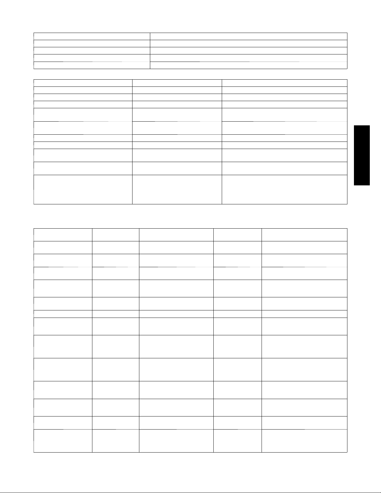
Table 3 – LED’s
The LED’s on the RTU Open show the status of certain functions
If this LED is on... Status is...
Power The RTU Open has power
Rx The RTU Open is receiving data from the network segment
Tx The RTU Open is transmitting data over the network segment
BO# The binary output is active
The Run and Error LED’s indicate control module and network status
If Run LED shows... And Error LED shows... Status is...
2 flashes per second Off Normal
2 flashes per second 2 flashes, alternating with Run LED Five minute auto ---restart delay after system error
2 flashes per second 3flashes,thenoff Control module has just been formatted
2 flashes per second 4 flashes, then pause Two or more devices on this network have the same
2 flashes per second On Exec halted after frequent system errors or control pro-
5 flashes per second On Exec start---up aborted, Boot is running
5 flashes per second Off Firmware transfer in progress, Boot is running
7 flashes per second 7 flashes per second, alternating with
Run LED
14 flashes per second 14 flashes per second, alternating with
Run LED
On On Failure. Try the following solutions:
MSTP network address
grams halted
Ten second recovery period after brownout
Brownout
--- Turn the RTU Open off, then on.
--- F o r m a t t h e R T U O p e n .
--- Download memory to the RTU Open.
--- Replace the RTU Open.
48---50LHTCQ---01T
Table4–RTUOpenAlarms
POINT NAME
Safety Chain safety_alarm Immediate Shutdown Automatic Over load Indoor Fan or Electric Heater
Fire Shutdown fire_alarm Immediate Shutdown Automatic Smoke detected by smoke detector or
Gas Valve igc_alarm Immediately operate fan at high-
Supply Fan sfan_fail_alarm Immediately disable
Supply Fan in Hand sfan_hand_alarm Ramp down Operations Automatic Bad Fan Status Switch, Configuration
Compressor Status comp_alarm Alert Generated Automatic Compressor would not start
Space Temp Sensor spt_ fail Ramp down Operations Automatic Bad sensor, bad wiring, failure to receive
ZS Sensor zst_sensor_fail Alert Generated Automatic Th is alarm indicates a communication
ZS Configuration zs_config_fail Alert Generated Automatic This alarm indicates that at least one ZS
Supply Air Temp Sensor loc_sat_sensor_fail Ramp down Operations Automatic Faulty, shorted, or open thermistor
Local OAT Sensor ioc_oat_sensor_fail May cause Economizer and Low
Outdoor Air Temp Sensor oat_fail Economizer and Low ambient D X
Space Relative
Humidity Sensor
BACnet Object
NAME
sprh_sensor_fail D ehumidification disabled Automatic Sensor reading is out of range. Bad
ACTION TAKEN BY
CONTROL
est speed
Operation
ambient DX cooling lockout to be
disabled
cooling lockout disabled.
RESET METHOD PROBABLE CAUSE
overheat
configuration incorrect
Automatic G as valve stuck open after heating cycle,
Automatic Tripped Circuit Breaker, Broken belt,
Automatic Faulty, shorted, or open thermistor
Automatic Failure to receive va lid local or ne twork
causing heat to continue to operate.
Bad indoor fan motor, Configuration
incorrect, Bad fan status switch.
incorrect.
Network or Linkage Space Temp value, or
sensor configured incorrec t ly.
failure of a connected ZS sensor that
previously had been actively
communicating.
sensor is configured in the Sensor
Binder properties and is not actually
communicating.
caused by wiring error or loose
connection.
caused by wiring error or loose
connection.
value for Outdoor Air Temperature
sensor, bad wiring, failure to receive
Network or Linkage RH value, or sensor
configured incorrectly.
27
Page 28

Table 4 -- RTU Open Alarms (cont)
POINT NAME
Indoor Air Quality Sensor iaq_sensor_fail No IAQ Operation Automatic Sensor reading is out of range. Bad
Outdoor Air Quality Sensor oaq_fail Control uses default OAQ value of
Economizer Operation econ_opr Alert Generated Automatic This alarm is active whenever an
Space Temperature spt_alrm_status Alert Generated Automatic Space Temperature value is less than
Supply Air Temperature sat_alarm Alert Generated Automatic SAT is greater than the high limit value
Setpoint Slider slidepot_alarm Set Offset to zero Automatic STO sensor is open for more than 5
Switch Configuration di_cfg_alarm Disable only wrong switch
48---50LHTCQ---01T
Analog Input
Configuration
Space Relative Humidity sprh_hi_alarm Alert Generated Automatic Indoor RH is greater than the high limit
Indoor Air Quality iaq_alarm Alert Generated Automatic CO2ppm reading is above the
Supply Fan Runtime sfan_rntm_alarm Alert Generated zero the timer Supply fan run time exceeded user
Compressor 1 Runtime comp1_rntm_alarm Alert Gener ated zero the timer Compressor #1 run time limit is exceeded
Compressor 2 Runtime comp2_rntm_alarm Alert Gener ated zero the timer Compressor #2 run time limit is exceeded
Filter filter_alarm Alert Generated Automatic / reset
Airside Linkage Alarm air_linkage_fail Alert Generated Automatic Airside Linkage communication from VVT
BACnet Object
NAME
ai_cfg_alarm Disable 4 selectable analog inputs Configure correctly More than one analog input is
ACTION TAKEN BY
400 ppm.
functions
CONTROL
RESET METHOD PROBABLE CAUSE
sensor, bad wiring, failure to receive
Network or Linkage RH value, or sensor
configured incorrectly.
Automatic Sensor reading is out of range. Bad
Configure correctly More than one discrete input is configured
timer
sensor, bad wiring, failure to receive
Networkvalue,orsensorconfigured
incorrectly.
economizer fault is detected as required
by the California Title 24 Economizer
FDD logic.
Economizer fault conditions include;
Failed to Fully Open, Failed to Open,
Failed to Close, and Stuck Open.
the low limit value or greater than the
high limit value
or less than the low l imit value for more
than 5 minutes
seconds
to provide the same function.
configured to provide the same
function.
value or less than the low limit value for
more then 15 minutes
configuration for 1 minute
defined limit
Dirty Filter, supply fan run time exceeded,
filter switch configuration wrong.
master terminal has stopped or failed
28
Page 29

Alarms
Alarms are provided to indicate a possible problem with
the controller or unit. Alarms can be checked through a
network and/or the local access device. All alarms are
listed in Table 4 with name, object name, action taken by
control, reset method, and possible cause. Some alarms
can occur based on specific configurations.
Safety Chain Alarm
This alarm occurs immediately if a field installed,
normally closed, safety contact opens and interrupts
24VAC signal input #4 (J1--9). The Unit Status will be
Shutdown and the System Mode will be Disable. All unit
operations stop immediately and will not restart until the
alarm automatically clears. There are no configurations
for this alarm; it is all based on field installed wiring. This
alarm will not occur if Fire Shutdown Alarm is active.
Normal operation resumes when the safety chain circuit is
complete.
Fire/Smoke Shutdown Alarm
This alarm occurs immediately when the smoke detector
senses smoke. The Unit Status will be Shutdown and the
System Mode will be Disable. All unit operations stop
immediately and will not restart until the alarm
automatically clears. If there is not a smoke detector
installed or the smoke detector did not trip, check input
configurations.
NOTE: The default function for input 5 is a normally
open Fire Shutdown input.
Gas Valve Alarm
This alarm occurs 60 second after gas heat has been
de--energized but the Integrated Gas Control (IGC) board
is still indicating a need for fan operation. Upon alarm
detection, the fan will start immediately and run at its
highest speed.
NOTE: The default function for input 9 is a normally
open IGC input for LC WeatherExpert units.
Supply Fan Failure
This alarm occurs when the indoor fan is being command
on and the fan status switch feedback is showing the fan
off. This will end current operating mode and disable unit
operation. This alarm requires a fan status switch to be
configured on one of the inputs.
Supply Fan in Hand
This alarm occurs when the indoor fan is being
commanded off and the fan status switch feedback is
showing the fan is on. This will prevent any operating
mode and disable unit operation. This alarm requires a fan
status switch to be configured on one of the inputs.
Compressor Status
This alarm indicates the base unit’s compressor safety
circuit is energized. Cooling, heating, and supply fan
outputs are not interrupted. Normal operation resumes
when the compressor safety circuit is de-energized. This
alarm requires field use of this described compressor
safety circuit.
Space Temp Sensor
This alarm occurs if the space sensor wired to the RTU
Open is disconnected or shorted for more than 10 seconds or
if the SPT value from the Network or Airside Linkage is no
longer being received. When this occurs the Unit Status will
be Shutdown and the System Mode will be Run. Sensor,
sensor connections, wiring, board connection, and
configurations should be checked for faults or errors. Alarm
will reset automatically when cause is fixed.
ZS Sensor
This alarm occurs if the ZS sensor wired to the RTU Open
stops communicating with the controller.
ZS Sensor -- This alarm indicates a communication
failure of a connected ZS sensor that previously had been
actively communicating. The alarm is reset when normal
ZS sensor communications resume, if power is cycled to
the controller, or if the Shutdown point is set to Active.
ZS Configuration -- This alarm indicates that at least one
ZS sensor is configured in the Sensor Binder properties
and is not actually communicating. The alarm is reset
when the configured ZS sensor is communicating or the
configuration is changed to reflect the sensor is no longer
connected to the Rnet.
Supply Air Temp Sensor
This alarm occurs immediately when the supply air
temperature sensor wired to the RTU Open is
disconnected or shorted. When this occurs the Unit Status
will be Shutdown and the System Mode will be Run.
Sensor, sensor connections, wiring, board connection, and
configurations should be checked for faults or errors.
Alarm will reset automatically when cause is fixed.
Local OAT Sensor
This alarm occurs when the outdoor air sensor indicates a
short or open circuit or the Network OAT value is no
longer being received. Economizer cooling and optimal
start functions are disabled. Normal operation resumes
when the controller detects a valid sensor.
Outdoor Air Temp Sensor
This alarm indicates that a valid OAT sensor value is no
longer available to the controller after having been
available previously.
Economizer Operation -- This alarm is active whenever
an economizer fault is detected as required by California
Title 24 Economizer FDD logic. Once detected, this alarm
will stay active until the Shutdown input is set to Active
or the fan is stopped.
Economizer -- This point indicates the specific fault
detected and annunciated by the Economizer Operation
alarm above. Detected fault conditions include: Failed to
Fully Open, Failed to Open, Failed to Close, and Stuck
Open.
Space Relative Humidity Sensor
This alarm indicates the mA input at the associated
channel falls below 3.5 mA or rises above 21 mA, or the
Network value for space RH is no longer being received.
Cooling, heating, and supply fan operation continues,
however, the controller’s Humidi-MiZer binary output is
disabled until the fault condition is corrected.
IAQ Sensor
This alarm indicates the mA input at the associated
channel falls below 3.5 mA or rises above 21 mA, or the
Network value for space RH is no longer being received.
48---50LHTCQ---01T
29
Page 30

Cooling, heating, and supply fan operation continues.
However, the controller’s IAQ control function is disabled
until the fault condition is corrected.
OAQ Sensor
This alarm indicates the mA input at the associated
channel falls below 3.5 mA or rises above 21 mA, or the
Network value for space RH is no longer being received.
Cooling, heating, and supply fan operation continues.
However, the controller’s IAQ control function uses
400ppm as the fixed outdoor air CO2 level until the fault
condition is corrected.
Space Temperature
When Occupied, a Space Temperature alarm is generated
if the space temperature falls below the lower limit or
rises above the upper limit.
When Unoccupied, an unoccupied space temperature
alarm is generated when the space temperature falls below
the alarm configuration Unoccupied Low SPT Alarm
Limit or when the space temperature rises above the alarm
configuration Unoccupied High SPT Alarm Limit.
The following values are related to the Space Temperature
48---50LHTCQ---01T
alarm:
Alarming Temperature – This variable displays the value
of the space temperature that caused the alarm and is only
visible when the space temperature is in an alarm state.
Alarm Limit Exceeded – This variable displays the value
of the alarm setpoint that was exceeded by the alarming
space temperature and is only visible when the space
temperature is in an alarm state.
Supply Air Temperature
This alarm indicates the supply air temperature fell below
the alarm configuration Low SAT Alarm Limit or
exceeded the alarm configuration High SAT Alarm Limit
for 5 minutes. This alarm is inhibited until the RTU has
been running for 30 minutes to allow for system
stabilization after startup.
Setpoint Slider
This alarm indicates an open circuit is detected at the
setpoint adjustment input. This can only occur if the
Space Sensor Type is set to T56. Note that only an open
circuit results in an alarm. A short across this input offsets
the setpoints negatively by the amount configured by
configuration Setpoint Adjustment Range.
Switch Configuration
This occurs if more than one binary input (inputs 3, 5, 8,
and 9) is configured for the same function. When this
happens the two inputs (or more) configured wrong will
be disabled as an inputs. This alarm will automatically be
cleared when configuration is corrected.
An example of this would be: Input 3 = Compressor
Safety, input 5 = Fan Status, input 8 = Fan Status, and
input 9 = Humidistat; the alarm would be active, unit
would run, compressor safety and humidistat would
function normally, and Fan Status (inputs 5 & 8) will be
interpreted as “No Function.”
Analog Input Configuration
This occurs if more than one analog input (inputs 1 & 2)
is configured for the same sensor. When this happens the
two inputs will be disabled as inputs. This alarm will
automatically be cleared when configuration is corrected.
An example of this would be: Input 1 = IAQ Sensor, input
2 = IAQ Sensor; the alarm would be active, unit would
run, but the IAQ Sensor (inputs 1 & 2) will be interpreted
as “No Function.”
Space Relative Humidity
This alarm indicates the space humidity fell below the
alarm configuration Low Space Humidity Alarm Limit or
exceeded the alarm configuration High Space Humidity
Alarm Limit for 10 minutes. This alarm is inhibited until
the RTU runs for 15 minutes to allow for system
stabilization after startup.
Indoor Air Quality
This alarm indicates the space CO2level exceeds the
alarm configuration Occupied High CO
1-minute. This alarm will be inhibited until the RTU has
been running for 2-minutes to allow for system
stabilization after startup.
Alarm Limit for
2
Supply Fan Runtime
This alarm indicates the accumulated runtime exceeds the
unit configuration Supply Fan Service Alarm Timer value
(when not set to 0). This alarm is most commonly used to
indicate an equipment maintenance interval is due. The
supply fan runtime accumulator may be reset by setting
the maintenance point Reset Supply Fan Runtime Alarm
to Clear, and then back to Run – acknowledging each
selection by clicking the OK button when it appears.
Setting unit configuration Supply Fan Service Timer value
to 0 disables the supply fan runtime alarm function.
Compressor 1 Runtime
This alarm indicates the accumulated runtime exceeds the
unit configuration Compressor 1 Service Alarm Timer value
(when not set to 0). This alarm is most commonly used to
indicate an equipment maintenance interval is due. The
Compressor 1 Runtime accumulator may be reset by setting
the maintenance point Reset Comp 1 Runtime Alarm to
Clear, and then back to Run – acknowledging each selection
by clicking the OK button when it appears. Setting unit
configuration Compressor 1 Service Timer value to 0
disables the Compressor 1 Runtime alarm function.
Compressor 2 Runtime
This alarm indicates the accumulated runtime exceeds the
unit configuration Compressor 2 Service Alarm Timer
value (when not set to 0). This alarm is most commonly
used to indicate an equipment maintenance interval is due.
The Compressor 2 runtime accumulator may be reset by
setting the maintenance point Reset Comp 2 Runtime
Alarm to Clear, and then back to Run – acknowledging
each selection by clicking the OK button when it appears.
Setting unit configuration Compressor 2 Service Timer
value to 0 disables the Compressor 2 runtime alarm
function. Note that this function is unavailable if the
service configuration Compressor Stages value is not set
to Two Stages.
Filter
This alarm indicates the accumulated runtime exceeds the
unit configuration Filter Service Alarm Timer value
(when not set to 0). This alarm is most commonly used to
indicate a filter replacement is due. Reset the filter service
30
Page 31

runtime accumulator by setting the maintenance point
Reset Filter Runtime Alarm to On, back to Off, and
clicking the OK button after each setting. Setting unit
configuration Filter Service Alarm Timer value to 0
disables the filter service alarm function.
Airside Linkage Alarm
This alarm indicates that RTU Open was connected to a
zoned system using Airside Linkage and it lost
communications with its linkage master or it is receiving
data from multiple masters.
Performance
Current Performance Data
The RTU Open collects performance data during
operation. The data can be used to monitor the operation
of the unit over time.
Equipment Runtime
The RTU monitors the supply fan and records the amount
of time the unit has been operating. This value will
continue to accumulate runtime until Performance Data
has been changed to Reset or will also automatically reset
every 24 hours at midnight if Save Performance Data
Daily is set to Enable.
Economizer Utilization
The amount of time the equipment has operated in the
economizer mode as a percentage of the equipment
runtime above. This value will continue to accumulate
runtime until Performance Data has been changed to
Reset or will automatically reset every 24 hours at
midnight if Save Performance Data Daily is set to Enable.
DCV Utilization
The amount of time the equipment has provided Demand
Controlled Ventilation as a percentage of the equipment
runtime above. This value will continue to accumulate
runtime until Performance Data has been changed to
Reset or will automatically reset every 24 hours at
midnight if Save Performance Data Daily is set to Enable.
Unocc Free Cool Utilization
The amount of time the equipment has provided Free
Cooling while unoccupied as a percentage of the
equipment runtime above. This value will continue to
accumulate runtime until Performance Data has been
changed to Reset or will automatically reset every 24
hours at midnight if Save Performance Data Daily is set to
Enable.
Part Load Cooling Utilization
The amount of time the equipment has operated in the
cooling mode but at less than 100% full cooling capacity
as a percentage of the equipment runtime above. This
value will continue to accumulate runtime until
Performance Data has been changed to Reset or will
automatically reset every 24 hours at midnight if Save
Performance Data Daily is set to Enable.
Full Load Cooling Utilization
The amount of time the equipment has operated in the
cooling mode at 100% full cooling capacity as a
percentage of the equipment runtime above. This value
will continue to accumulate runtime until Performance
Data has been changed to Reset or will automatically reset
every 24 hours at midnight if Save Performance Data
Daily is set to Enable.
Heating Utilization
The amount of time the equipment has operated in the
heating mode as a percentage of the equipment runtime
above. This value will continue to accumulate runtime
until Performance Data has been changed to Reset or will
automatically reset every 24 hours at midnight if Save
Performance Data Daily is set to Enable.
Recorded High OAT
The highest value of OAT noted since the last reset
occurred. This value will continue to update until
Performance Data has been changed to Reset or will
automatically reset every 24 hours at midnight if Save
Performance Data Daily is set to Enable.
Recorded Low OAT
The lowest value of OAT noted since the last reset
occurred. This value will continue to update until
Performance Data has been changed to Reset or will
automatically reset every 24 hours at midnight if Save
Performance Data Daily is set to Enable
Performance Data
Indicates the mode that is currently in effect. This point is
used to reset all of the above performance data manually
at any time.
Range = Collect/Reset Default = Collect
Historical Performance Data
The RTU Open collects historical performance every time
the performance data above has been reset.
Save Performance Data Daily
If set to Enable, the control will automatically transfer the
Current Performance Data directly to the Historical
Performance Data values for each entry once every 24 hours
at midnight. All Historical data will only be available for
viewing for the next 24 hours. Also, all current performance
data will be reset after the data has been transferred.
Range = Disable/Enable Default = Enable
Equipment Runtime
The value of the equipment runtime when the current
performance data was last reset.
Economizer Utilization
The value of the Economizer Utilization when the current
performance data was last reset.
DCV Utilization
The value of the DCV Utilization when the current
performance data was last reset.
Unocc Free Cool Utilization
The value of the Unocc Free Cool Utilization when the
current performance data was last reset.
Part Load Cooling Utilization
The value of the Part Load Cooling Utilization when the
current performance data was last reset.
Full Load Cooling Utilization
The value of the Full Load Cooling Utilization when the
current performance data was last reset.
48---50LHTCQ---01T
31
Page 32

Heating Utilization
The value of the Heating Utilization when the current
performance data was last reset.
Previous High OAT
The value of the Recorded High OAT when the current
performance data was last reset.
Previous Low OAT
The value of the Recorded Low OAT when the current
performance data was last reset.
Table 5 – Manufacture Date
When troubleshooting, you may need to know a control module’s manufacture date.
Obtain the manufacture date from a... Notes
Module status report (modstat) To obtain a modstat with Field Assistant:
Sticker on the control board
“Serial No: OR2YMCxxxP”
(Bar Coded & Typed Number)
48---50LHTCQ---01T
1. Press Function (FN) key and hold.
2. Then press period (.)
3. Release both buttons.
ThereportshowsthedateunderMain board hardware.
The serial numbers are unique and contain embedded information, for example OR2420042P:
“OR2” --- These first three digits are unique to RTU Open and are used as an identifier.
“YM” --- These two digits identify the last digit of the year and month (in hex, A=10/Oct)
of manufacture. “42” would represent a date of manufacture of “Feb 2014”.
“C” --- T h o u s a n d s c o u n t e r 0 --- 9 a n d A --- Z ; A = 1 0 ; Z = 3 5
“xxx” --- These three digits represent the sequential number of units produced for a given
product for the mentioned manufacturing time period.
“P” --- This final digit represents the decade and toggles between “N” and “M” every
ten years.
Third Party Networking
Third party communication and networking troubleshooting
should be done by or with assistance from the front end 3rd
party technician. A Module Status Report (Modstat) can be
run from Field Assistant or Equipment Touch (see Table 5 to
perform). This lists information about the board status and
networking state. For basic troubleshooting, see Table 6.
Refer to the RTU Open v3 Integration Guide for additional
information.
Table 6 – Basic Protocol Troubleshooting
Problem Possible cause Corrective action
No communication with 3rd
party vendor
Incorrect settings on SW1, SW2 and SW3 V erify and correct switch settings. Cycle
RS485 Port has no voltage output
(check with RTU Open disconnected from RS485
communication bus):
•Bacnet
• Bacnet @ 38.4K --- .06 to .09vdc
• Bacnet @ 76.8K --- .1vdc
• Modbus @ 9600 --- 76.8K --- .124vdc
• N2 @ 9600 --- .124vdc
Verify devices are daisy chained and repeaters an d bias
terminators are correctly installed.
R
@ 9600/19.2K --- .01 to .045vdc
powertoRTUOpenafterchangingswitch
settings.
Verify RTU Open has correct power
supply.
Possible bad driver on board.
Check RS485 bus for external voltage
before reconnecting to the bus.
Check 3rd party vendor RS485
communication wiring guidelines and
troubleshooting procedures.
32
Page 33
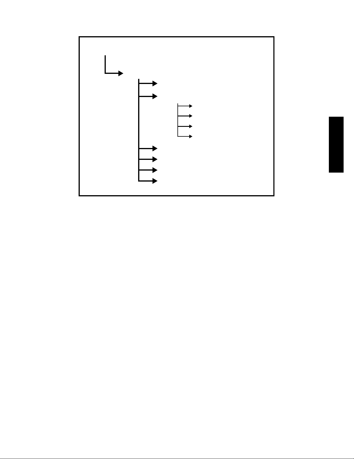
APPENDIX A -- USER INTERFACE MENUS
Field Assistant Navigation
Properties
Control Program
Status
Configuration
Unit Configuration
Setpoints
Alarm Configuration
Service Configuration
Maintenance
Performance
Alarms
Linkage
48---50LHTCQ---01T
C14143
33
Page 34

Equipment Touch Menu
RTU Properties Menu>
Status
48---50LHTCQ---01T
RTU Properties Menu>
Unit Configuration>
APPENDIX A -- USER INTERFACE MENUS (CON’T)
Access
Level
3=ADMIN
2=USER
1=No P W
3, 2, 1 Equi pment Status mode_status 1=Disabl ed
3,2,1 Syst em Mode run_status 1=O ff
3,2,1 S F an Status sf an_status Off/Running N/A
N/A Supply Fan S tatus
3,2,1 Supply F an VFD
3,2,1 Space T emperature - P rime Variabl e space_tem p xxx °F
3,2,1 Supply A ir Temperat ure sa_temp xxx °F
3,2,1 Outdoor A ir Temperat ure oa_temp xxx °F
3,2,1 Space R elative Humi dity space_rh 0- 100 %
3,2,1 Indoor A ir CO2 iaq 0-5000 ppm
3,2,1 Outdoor A ir CO2 oaq 0-5000 ppm
3,2,1 Economi zer Output econ_output 0-100 % open
3,2,1 Shutdow n shutdow n Inactive/Active
3 Fan Mode fan_mode 1=Auto
3 Pow er Fail Res tart Delay start_delay 0-30 sec 5
3 Minimum Cooli ng SAT sat_cl_min 45-75_F 50
3 Maximum Heating SAT sat_ht_max 85-150_F 120
N/A Vent Dm pr Pos / DC V Min Pos econ_min 0-100% Open 20
N/A Economizer P urge Min Pos ec on_purge_min 0-100% O pen 40
N/A LowFanEconMinPos
N/A DCV M ax Vent Damper P os iaq_dpr_max 0-75% Open 50
N/A S Fan Service AlarmTimer sfan_service_hrs 0-9999 hr 600 N/A
N/A 3 Supply F an Service Al arm Timer sf an_service_hrs 0-9999 hr 600
N/A Comp 1 S ervice Alarm T imer comp1_servic e_hrs 0-9999 hr 0
N/A Comp 2 S ervice Alarm T imer comp2_servic e_hrs 0-9999 hr 0
3 Filter ServiceAlarm Timer filter _service_hrs 0-9999 hr 600
N/A Door Al arm Delay door_al arm_delay 0-180 sec 60
3 Pushbut ton Override pb_enabl e Disable/ Enable Enable
3 Set point Adjustment stpt_adj_enable Di sable/Enable Enable
3 Set point Adjustment Range stpt_adj_r ange +/-0-5_F 5
3 Cool ing Lockout Temperat ure oat _cl_lockout 0-80_F 45
3 Economi zer High OA T Lockout Temp oat_ec_lock out 55-80_F 75
N/A HP Rev C ycle Lockout Temp
N/A HP Aux Heat Lockout T emp
3 Heat ing Lockout Temperat ure oat_ht _lockout 35-150_F 65
N/A Pre Occupanc y Purge preocc _purge Disabl e/Enable Disable
3 Purge Time purge_t ime 0-240 mi n 60 min
3 Unocc F ree Cool ntfc_ena Disable/E nable Disable
N/A Min Set point Separati on min_stpt_sep 2-10_F 5
N/A Occupancy Sour ce occ_source 1=A lways Occupied
1
= This point is only visible when Input 3, 5, 8, or 9 i s confi gured for Fan Status
2
= This point will be hidden f rom vi ew if U ni t Type is configured for LC WeatherExpert
3
= This point is only visible when Fan Control is configured for Variable Speed
4
= This point is only visible when Fan Control is configured for Two Speed
5
= This point is only visible when Uni t Type is configured for HP O/B Ctrl or HP Y 1/W1 Ctrl
POINT NAME BACnet Object RANGE DEFAULT Field Assistant Menu
1
2
Fan / S peed
3
Fan OffDelay fan_delay_off 0-180 sec 90
4
5
5
STATUS
2=Test
3=Run
2=Fan Onl y
3=Economizer Cooling
4=Cooling
5=Heating
6=Dehumidi fication
7=Test
8=Shutdown
9=Unocc F ree Cooling
10=Fire S hutdown
11=IAQ Ov erride
12=Pre-occ P urge
13=IGC Over ride
sfan_status Off/Running
fan_run 1=Off
2=Low
3=Med
4=High
5=On
vfd_output 0-100 %
UNIT CONFIGURATION
2=Continuous
3=Always On
econ_min_2 0-100% Open 33
hp_rev_cycle_lockout -20- 65_F -3
oat_auxht_lockout -20-65_F 40
2=BACnet Schedule
3=BAS on/ off
4=Remote O cc Input
Properties>Control Program
>Status
Continuous Properties>Control Program>
Configuration>
Unit Configuration
Always O ccupied
34
Page 35

Equipment Touch Menu
RTU Properties Menu>
Startu p Wizard
Field A ssistant Only
APPENDIX A -- USER INTERFACE MENUS (CON’T)
Access
Level
3=ADMIN
2=USER
1=No P W
3 Input 1 Functi on ai1_funct ion 1=No Sensor
3 Input 2 Functi on ai2_funct ion 1=No Sensor
3 Input 3 Functi on di3_funct ion 1=No Funct ion
N/A Input 3 Sw itch Configur ation di3_t ype N/O
3 Input 5 Functi on di5_funct ion 1=No Funct ion
3 Input 5 Swit ch Configurati on di5_type N/O
3 Input 8 Functi on di8_funct ion 1=No Funct ion
3 Input 8 Swit ch Configurati on di8_type N/O
3 Input 9 Functi on di9_funct ion 1=No Funct ion
3 Input 9 Swit ch Configurati on di9_type N/O
N/A ZS S ensor Binder zs_bi nder Rnet/ Unused Rnet
N/A ZS ZoneTemp zs_zone_temp Zone Temp ( 1-5) Mai n ZS Sensor
N/A ZS Z one Humidity zs_zone_humidit y Zone Hum idity (1-5) Mai n ZS Sensor
N/A ZS ZoneCO2 zs_zone_co2 Z one CO2 (1-5) Main Z S Sensor
POINT NAME BACnet Object RANGE DEFAULT Fi eld Assistant Menu
INPUT CONFIGURATION
2=IAO S ensor
3=OAQ S ensor
4=Space RH Sensor
2=IAO S ensor
3=OAQ S ensor
4=Space RH Sensor
2=Compressor S afety
3=Fan Status
4=Fil ter Status
5=Remote O ccupancy
6=Door C ontact
N/C
2=Fire S hutdown
3=Fan Status
4=Fil ter Status
5=Remote O ccupancy
6=Door C ontact
N/C
2=Enthalpy S witch
3=Fan Status
4=Fil ter Status
5=Remote O ccupancy
6=Door C ontact
N/C
2=Humidi stat
3=Fan Status
4=Fil ter Status
5=Remote O ccupancy
6=Door C ontact
7=IGC Over ride
Space sensor t ype spt_type 1=T55
SENSOR CALIBRATION
Space Tem perature l cl_space_temp
Space Tem p Calibration spt_offset - 9.9-10°F 0
Space RH lcl_space_rh 0-100%
Space AQ lcl_space_aq 0- 5000ppm
Supply A ir Temperatur e lcl_sa_tem p -56-245°F
Supply A ir Temp Cal ibration sat_offset -9. 9-10°F 0
Outdoor A ir Temperatur e lc_oa_temp -56-245°F
Outdoor A ir Temp Cal ibration oat_of fset -9.9-10°F 0
N/C
2=T56 (use f or T59)
3=SPT S ensor
4=None
5=ZS S ensor
IAQ S ensor Properties>Control Program>
No Sensor
Compressor S afety
N/O
Fire S hutdown
N/C
Enthalpy S witch
N/O
Humidis tat
IGC O verride (48 Ser ies LC
WeatherExpert units)
N/O
None
Configuration>
Unit Configuration>
Input Configuration
Properties>Control Program>
Configuration>
Unit Configuration>
Sensor Calibration
48---50LHTCQ---01T
35
Page 36

Equipment Touch Menu
RTU Properties Menu>
Unit Configuration>
RTU Properties Menu>
Alarm Configuration>
48---50LHTCQ---01T
RTU Properties Menu>
Alarm Configuration>
RTU Properties Menu>
Alarm Configuration>
RTU Properties Menu>
Alarm Configuration>
APPENDIX A -- USER INTERFACE MENUS (CON’T)
Access
Level
3=ADMIN
2=USER
1=No P W
3 Occupi ed Heating Set point occupied_heat _setpoint 40-90 °F 70 Properties>Control Program>
3 Occupi ed Cooling Set point oc cupied_cool_setpoint 55- 99 °F 76
3 Unoccupi ed Heating Set point unoccupied_heat_s etpoint 40-90 °F 55
3 Unoccupi ed Cooling Set point unoccupi ed_cool_setpoint 45-99 °F 90
N/A Effect ive Heat Set point eff ective_heat_setpoint 0-120 °F
N/A Effect ive Cool Set point ef fective_cool_setpoi nt 0-120 °F
3 Optimal Start opt m_start 0-4 hr 1
3 Optimal Start Type start_type 1=N one
3 Heat S tart K f actor (min/deg) h_kf actor 0- 99 15
3 Cool Start K factor ( min/deg) c_kfactor 0-99 15
3 Occ Rel ative Humidi ty Setpoint occ_dehum_stpt 0-unocc setpoi nt %rh 60
3 Unocc R elative Humidi ty Setpoint unocc _dehum_stpt 30- 100 %rh 95
3 DCV Max Ctr l Setpoint iaq_stpt _max 0-9999 ppm 650
3 Pow er Exhaust Setpoi nt
3 Occupi ed Alarm Hyst eresis occ_spt_alrm_hyst 0-20°F 5
N/A Alarm D elay (min/deg) spt _alrm_delay 0-60 mi nutes 10
3 Unoccupi ed Low SPT A larm Limit uno_spt_alr m_lo_lmt 35- 90 °F 45
3 Unoccupi ed High SPT Alarm Li mit uno_spt_alr m_hi_lmt 45- 100 °F 95
3 Low SAT Alarm Limit sat_l o_alrm_lim 15- 90 °F 38
3 High SAT Alarm Limit sat _hi_alrm_lim 90-175 °F 160
3 Occupi ed High RH A larm Limit (%RH) sprh_hi_alr m_lim 0- 100%rh 70%rh
7
3 Al arm Delay (mi n/%RH) sprh_delay 0-30 mi n 5min
3 Unoccupi ed High RH A larm Limit
N/A Low RH A larm Limit (%RH) sprh_lo_alrm_l im 0-100%rh 30%rh
3 Occupi ed High CO2 A larm Limit (ppm) iaq_occ_hi_l mt 0-9999 ppm 1200 Properties>Control Program>
8
6
= This point is hidden from view when Continuous Occupied Exhaust is enabled
7
= This menu is hidden from view when RH Control is set to Disable
8
=ThismenuishiddenfromviewwhenDCVControlissettoDisable
POINT NAME BACnet Object RANGE DEFAULT Fi eld Assistant Menu
6
(%RH)
SETPOINT
2=Temp C ompensated
3=Learning A daptive
pexh_stpt 20-90 %O pen 50
SPACE TEMPERATURE ALARM
SUPPLY TEMPERATURE ALARM
SPACE HUMIDITY ALARM
unocc_sprh_lmt 0-100%r h 100%rh
IAQ / VENTILATION ALARM
Temperatur e Compensated
Configuration>Setpoints
Properties>Control Program>
Configuration>
Alarm Configuration>
Space T emperature Al arm
Properties>Control Program>
Configuration>
Alarm Configuration>
Supply TemperatureAlarm
Properties>Control Program>
Configuration>
Alarm Configuration>
Space H umidity A larm
Configuration>
Alarm Configuration>
IAQ /Ventilation Alarm
36
Page 37

APPENDIX A -- USER INTERFACE MENUS (CON’T)
Access
Equipment Touch Menu
RTU Properties Menu>
Startu p Wizard
9
= This point is visible when Fan Control is configured for Variable Speed and not LC WeatherExpert
10
= This point is visible when Unit Type is confi gured for HP O/B Ctrl
11
= These points are not visible when uni t type is configured for LC WeatherExpert
Level
3=ADMIN
2=USER
1=No P W
3 Unit Type unit_type 1=Heat/C ool
3 Compressor Stages
N/A FaceSplit Coil
3 Economizer Exists econ_exi st No/Yes No (No FIOP)
3 Fan Cont rol
N/A VFD Input vfd_in_type 0- 10Vdc/2-10Vdc 2-10Vdc
N/A Max VFD Out put max_vfd_spd 33-100% 100%
N/A Min VFD Output min_vfd_spd 15- 100% 40%
N/A Dehum Min V FD Output dehum_min_v fd 50-100% 60%
3 Reversi ng Valve Output
3 Heat T ype heat_ty pe Electric/Gas Gas (48 S eries Units)
3 Number of Heat S tages heat_stages 1=1 st age
N/A Continuous Occupi ed Exhaust occ_exh No/Yes No
3 RH Control rh_enable Disable/Enabl e E nable (Units wi th Humidi- MiZerR)
3 DCV Control dcv_enable Disable/E nable Disable
N/A Indoor CO2 S ensor Value @ Mi n mA i aq_ref_lo_ppm 0-9999ppm 0
N/A Indoor CO2 S ensor Value @ Max m A iaq_ref_hi _ppm 0-9999ppm 2000
N/A Outdoor CO2 S ensor Value @ Mi n mA oaq_r ef_lo_ppm 0-9999ppm 0
N/A Outdoor CO2 S ensor Value @ Max mA oaq_ref_hi _ppm 0-9999ppm 2000
N/A System Space T emperature system_spt
N/A System Space R H system_rh
N/A System Space A Q system_i aq
N/A System Out door AQ system_oaq
N/A System Cool Demand Level cool_dem and_level 0-3 0
N/A System Heat Demand Level heat_demand_level 0-3 0
N/A System Out door Air Tem perature syst em_oat
3 Economizer High OA T Lockout Temp oat_ec_lockout 55-80_F 75
3 Vent D mpr Pos / D CV Min Pos econ_min 0- 100% Open 20
3 Economizer Purge Mi n Pos econ_purge_min 0- 100% Open 40
3 LowFanEconMinPos ec on_min_2 0-100% Open 33
3 DCV Max V ent Damper Pos iaq_dpr_max 0-75% Open 50
3 HP Rev C ycle Lockout Temp hp_rev_cycle_lockout - 20-30_F -3
3 Occupancy S ource occ_source 1=Always Oc cupied
POINT NAME BACnet Object RANGE DEFAULT F ield Assistan t Menu
9
9, 11
11
10
comp_stages 1= One Stage
face_split Yes/No No
fan_type 1=Singl e Speed
rev_vlv_type O out put type/B output type O out put type
SERVICE CONFIGURATION
2=LC Weather Expert
3=HP O /B Ctrl
4=HP Y1/W1 Ctrl
2=Two S tages
2=Two S peed
3=Variabl e Speed
2=2 stages
3=0 stage
2=BACnet Schedule
3=BAS On/Off
4=Remote O cc Input
Heat/Cool (TC/ HC models, and LC
sizes 04-06) )
LC WeatherE xpert (LC si zes 07-26)
HP Y1/ W1 Cltl ( TCQ and HCQ models)
One Stage ( sizes 04-07, and
A08-A12)
Two S tages (TC/HC sizes 08-30 and
LC sizes 04- 06)
Three S tages (LC WeatherE xpert
sizes 07-26)
Yes (FIOP)
Single S peed (04-07 and A08-12)
Two S peed (units wit h SAV™ option)
Variabl e (LC WeatherExper t sizes
07-26)
Electr ic (50 Seri es Units)
0 ( 50 series cooli ng only units)
1 (All TCQs and HCQs,
Low Nox uni ts, single phase
gas units, TC04-09 l ow and
TC05-07 m ed heat 3 phase
gas units)
2 ( TC 04 and 08-09 med,
TC05-09 hi gh heat 3 phase
gas units, HC04-09 3 phase
gas units and al l 12-20 gas
units, i ncluding all LC uni ts)
Disable ( Units w/o H umidi-MiZerR)
Always O ccupied
Properties>
Control Program>
Configuration>
Service Configuration
Equipment T ouch Only
48---50LHTCQ---01T
37
Page 38

Equipment Touch Menu
RTU Properties Menu>
Maintenance (Unit)
48---50LHTCQ---01T
Field A ssistant Only
APPENDIX A -- USER INTERFACE MENUS (CON’T)
Access
Level
3=ADMIN
2=USER
1=No P W
3 O ccupancy Status occ_status Occupi ed/Unoccupied Properties>Control Program
N/A Temp Com pensated Start
3 P re Occupancy Purge purge Inactive/Active
N/A Space T emp Sensor spt_status 1= Sensor Failur e
3 E ffective Heat Setpoint effect ive_ht_stpt 0-120° F
3 E ffective Cool Setpoint eff ective_ci_stpt 0-120° F
N/A Relat ive Humidit y Source rh_sour ce 1=N/ A
N/A IAQ S ource iaq_source 1=N/A
N/A OAQ S ource oaq_sourc e 1=N/A
N/A Outdoor A ir Temperatur e Source oat_s tatus 1=N /A
N/A System Status
N/A Safet y Chain Feedback safety_status Off/Run Enabled
N/A Fir e Shutdown St atus firedow n_status Run Enabled/ Shutdown
N/A Compress or Safety St atus comp_status Normal/ Trouble
N/A Calcul ated Min Econ P os cal _min_econ_pos 0-100%
N/A Calcul ated PE Set point cal_pe_st pt 0-100%
3 A ctive Compressor Stages comp_r un 0-2
3 A ctive Heat S tages heat _run 0-2
N/A Enthal py Status enthalpy_st atus High/Low
N/A Enthal py BACnet oae H igh/Low
N/A Humi distat Input S tatus humstat_st atus High/ Low
N/A Fil ter Status filter_status Clean/Dir ty
N/A Door Cont act Status door_contact_status Off/On
3 R eset Supply Fan R untime Alarm sfan_r ntm_clr Run/Clear Run
N/A Reset C omp 1 Runtime A larm comp1_rnt m_clr Run/Cl ear Run
N/A Reset C omp 2 Runtime A larm comp2_rnt m_clr Run/Cl ear Run
3 Reset Filter Runtime Alarm fil ter_rntm_clr Off/On Off
POINT NAME BACnet Object RANGE DEFAULT Fi eld Assistan t Menu
SERVICE TEST
ServiceTest test_enabl e Disable/Enabl e Disable
Fan Test fan_test Disabl e/Enable Disable
High S peed Fan Test hi_spd_test Disable/E nable Disable
Compressor 1 Test comp1_test Di sable/Enable Disabl e
Compressor 2 Test comp2_test Di sable/Enable Disabl e
Heat 1 T est heat1_test Disabl e/Enable Disabl e
Heat 2 T est heat2_test Disabl e/Enable Disabl e
Reversing Valve T est rev_vl v_test Disabl e/Enable Disabl e
Dehumidif ication Test dehum_test Disable/ Enable Disable
Power E xhaust Test pexh_test Di sable/Enable Disabl e
Economizer T est econ_t est 0-100 %Open 0
VFD S peed Test vfd_spd_test 0-100% 0
UNIT MAINTENANCE
-Or-
Learning A daptive Start
tcs_status
-Or-
aos_status
Inactive/Active
2=SPT S ensor
3=T55/T 56
4=Networ k
5=Airsi de Linkage
6=Locked Val ue
2=Local
3=Networ k
4=Linkage
5=Locked Val ue
6=Linkage&Local
2=Local
3=Networ k
4=Linkage
5=Locked Val ue
6=Linkage&Local
2=Local
3=Networ k
4=Linkage
5=Locked Val ue
6=Linkage&Local
2=Local
3=Networ k
4=Linkage
5=Locked Val ue
Properties>Control Program>
Configuration>
Service Configuration>Service Test
Maintenance>Unit
38
Page 39
Equipment Touch Menu
RTU Properties Menu>
Maintenance (Occupancy)
Field A ssistant Only
RTU Properties Menu>
Maintenance(Airside Linkage)
RTU Properties Menu>
Performance
Field A ssistant Only
APPENDIX A -- USER INTERFACE MENUS (CON’T)
Access
Level
3=ADMIN
2=USER
1=No P W
3 BAS On / Off keypad_ovrde 1=I nactive
3 Pushbutt on Override pb_status Off/Active
N/A Occupancy Contact occ_cont act_status Off/On
3 Override Time Remaining ovrde_time 0-240 m in
3 Schedules schedule Unoccupi ed/Occupied
3 Supply F an Runtime sfan_rntm xxxxx hr Properties>Control Program
3, 2, 1 Equipment Runtime equip_rntm xxxxx hr
3, 2, 1 Economi zer Utilization econ_ut il 0-100%
3, 2, 1 DCV Utilization dcy_util 0-100%
3, 2, 1 Unocc Free CoolUtilization ntf c_util 0-100%
3, 2, 1 Part Load C ooling Utilization par tload_cool_util 0- 100%
3, 2, 1 Full Load Cooli ng Utilization cool_ut il 0-100%
3, 2, 1 HeatingUtilization heat_util 0-100%
3, 2, 1 Recorded Hi gh OAT rec_hi _oat -xxx - xxx_F
3, 2, 1 Recorded Low O AT rec_lo_oat -xxx - xxx_F
N/A Performance D ata Collect /Reset
POINT NAME BACnet Object RANGE DEFAULT Field A ssistant Menu
OCCUPANCY (MAINTENANCE)
2=Occupied
3=Unoccupied
RUNTIME (MAINTENANCE)
Supply F an Runtime sfan_rntm xxxxx hr
Compressor 1 Runti me comp1_r ntm xxxxx hr
Compressor 2 Runti me comp2_r ntm xxxxx hr
Filt er Runtime filter_r ntm xxxxx hr
AIRSIDE LINKAGE (MAINTENANCE)
CURRENT PERFORMANCE DATA
HISTORICAL PERFORMANCE DATA
Save Per formance Daily s ave_perf_data Disabl e/Enable Disabl e
Equipment R untime pre_equip_r ntm xxxxx.x hr
Economizer U tilization pre_econ_ut il 0-100%
DCV Utilization pre_dcv_util 0-100%
UnoccFree Cool Utilization pre_ntfc_uti l 0-100%
Part Load C ooling Utilization pr e_pl_cool_util 0-100%
Full Load C ooling Utilization pre_cool_uti l 0-100%
Heating Utilization pre_heat_util 0- 100%
Recorded Hi gh OAT pre_hi _oat -xxx - xxx_F
Recorded Low O AT pre_lo_oat -xxx - xxx_F
Inactive Properties>Control Program
Maintenance>Occupancy
Properties>Control Program
Maintenance>Runtime
Linkag e>Airside L inkage
Properties>Control Program>
Perfor mance>Current
Performance Data
Properties>Control Program>
Perfor mance>Histori cal
Performance Data
48---50LHTCQ---01T
39
Page 40

Equipment Touch Menu
RTU Properties Menu>
Alarms
48---50LHTCQ---01T
RTU Properties Menu>
Maintenanc e ( Airside Linkage)
APPENDIX A -- USER INTERFACE MENUS (CON’T)
Access
Level
3=ADMIN
2=USER
1=No PW
3, 2, 1 Safety Chain safe ty_alar m Normal/Alarm Propert ies>Control Program>
3, 2, 1 Space Temperatur e Alar m Status spt_ alrm_ status Normal/Alarm
3, 2, 1 ZS Temp Sensor N/A
3, 2, 1 ZS Sensor Configuration N/A
3, 2, 1 Space Temp Sensor sp t_fail Normal/Alarm
3, 2, 1 Supply Air Temperature sat_ alarm Normal/Alarm
3, 2, 1 Supply Air Temp Sensor loc_sat_sensor _fail Normal/Alarm
N/A Supply Fan Failure sfan_fail _alarm Normal/Alarm
3, 2, 1 Supply Fan in Hand sfan_hand _alarm Normal/Alarm
3, 2, 1 Supply Fan Runtime N/A
3, 2, 1 Indoor Air Quali ty iaq_ alarm Normal/Alarm
3, 2, 1 Indoor Air Quali ty Sensor iaq_sensor_alarm Normal/Alarm
3, 2, 1 Space Relative Humid ity sp rh_hi _alarm Normal/Alarm
3, 2, 1 Space Relative Humid ity Sensor sprh_ sensor_ fail Normal/Alarm
3, 2, 1 Filter filter_ alarm Clean/ Dirty
3, 2, 1 Local OAT Se nsor loc_oat_sensor _fail Normal/Alarm
3, 2, 1 Econom izer Op eration econ_opr Normal/Alarm
3, 2, 1 Switch Configuration di_cfg_alarm Normal/Alarm
3, 2, 1 Analog I nput Config uration ai_cfg_alarm Normal/Alarm
3, 2, 1 Supply Fan Runtime sfan _rntm _alarm Normal/Alarm
3, 2, 1 Compr essor 1 Run time comp1_rntm_alarm Normal/Alarm
3, 2, 1 Compr essor 2 Run time Comp2_rntm_alarm Normal/Alarm
3, 2, 1 Airside Linkage Alarm air_l inkage _fail Normal/Alarm
N/A Linkage Colle ctor link_collector Properties>Control Program
3 Airside Linkage Status a_link_status Not Active/Active
N/A Air Source Mod e link_ahu_mode 1=Off
N/A Air Source Supply Air Temp link_sat xxx_F
N/A Air Source O utdoor Air T emp link_ahu_oat xxx_F
N/A Num ber of Pr ovider s link_collector/4602 xx
N/A Occ upancy S tatus link_occ Unoccupied/Occupie d
N/A Space Temperature link_stp xxx_F
N/A Occupied Cooling Setpoint link_occ_ cl_stpt 55---80_F
N/A Occupied Heating Setpoint link_occ_Ht_stpt 55---80_F
N/A Unoccup ied Cooling Setpoint link_unocc_cl_stpt 75 ---130_F
N/A Unoccupied Heating Setpoint link_unocc_ht_stpt 55 ---85_F
N/A Indoor Air CO2 (ppm) link_iaq xxx p p m
N/A Space Relative Hum idity lin k_sprh xxx%
N/A Link age Max Dam per Position link_max_dmpr 0 ---100%
N/A Link age Op timal Star t a_link_opt_start Inactive/Active
POINT NA ME BACnet Object RANGE DEFAULT Field Assistant Menu
ALARMS
Alarms
AIRSIDE LINKAGE
Maintenanc e>Airside Linkage
2=Warmup
3=Heating
4=Cooling
5=Freecool
6=Pressu re
7=EVAC
8=Vent
If “Airside Link age Statu s is “ Active”, the following ar e shown as ap plicabl e:
40
Page 41
APPENDIX B -- THIRD PARTY POINTS LIST
RTU Open Protocol Maps
Point Name
SPT Sensor Read O nly °F
input_1 Read O nly no uni ts ai_1 AI:1001 Input R egister (Fl oat) 21 AI 2 Select
input_2 Read O nly no uni ts ai_2 AI:1002 Input R egister (Fl oat) 23 AI 3 Select
input_6 Read O nly °F ai _6 AI:1006 Input R egister (Fl oat) 5 AI 7 Select
input_7 Read O nly °F ai _7 AI:1007 Input R egister (Fl oat) 25 AI 4 Select
input_10 Read Onl y °F ai_10 AI: 1010 Input Register ( Float) 27 AI 5 Select
input_11 Read Onl y other ai_11 AI:1011 Input R egister (Fl oat) 29 AI 6 Select
slidepot vol tage reading Read O nly no uni ts slidepot_v olts A I:1012 Input Register (Float) 7 AI 8 Select
Active C ompressor Stages Read Onl y no uni ts comp_run AV :2020 I nput Register ( Float) 31 ADF 10 S NVT_count_inc(9) nvoCmpStages
Active H eat Stages Read Only no uni ts heat_run AV:2003 Input Register ( Float) 33 ADF 11 S NVT_count_inc(9) nv oHtStgs
Air S ource Outdoor Ai r Temp Read Only °F link_ahu_oat AV:2609 I nput Register ( Float) 11 ADF 2 Select
Air S ource Supply Ai r Temp Read Only °F link_sat A V:2608 Input Regis ter (Float) 13 ADF 3 Select
Compressor 1 Runti me Read Onl y hr comp1_r ntm A V:2017 I nput Register ( Float) 35 ADF 12 Select
Compressor 1ServiceAlarm Timer R/W hr comp1_serv ice_hrs AV:83006 Holding Regi ster (Float ) 37 ADF 13 Select
Compressor 2 Runti me Read Onl y hr comp2_r ntm A V:2018 I nput Register ( Float) 39 ADF 14 Select
Compressor 2ServiceAlarm Timer R/W hr comp2_serv ice_hrs AV:83007 Holding Regi ster (Float ) 41 ADF 15 Select
Cooling Lockout Temperatur e R/W °F oat_cl_l ockout AV :9002 H olding Register ( Float) 43 ADF 16 S NVT_temp_p(105) nviClLckTemp
DCV M ax Ctrl Set point R/W ppm iaq_st pt_max AV: 3013 Hol ding Register ( Float) 45 ADF 17 SNV T_ppm(29)
DCV M ax Vent Damper P os R/W %Open iaq_dpr_m ax AV:9011 H olding Register (Float) 47 ADF 18 SN VT_lev_percent(81) nvi DCVMaxPos
Dehum Mi n VFD Output R/W % dehum_min_vfd A V:3028 Select.. Select.. Select
Economizer H igh OAT Lockout Temp R/W °F oat_ec_loc kout AV:9008 Holding R egister (Fl oat) 49 ADF 19 Select
Economizer O utput Read O nly %Open econ_output A V:2022 Input Regist er (Float) 51 ADF 20 SNVT _lev_percent(81) nvoEconOut
Economizer P urge Min Pos R/W %Open econ_purge_m in AV:9029 Hol ding Register (F loat) 75 ADF 5 S NVT_lev_percent( 81) nvoEcnPr gMin
Economizer T est R/W %Open econ_t est AV:81001 Holding R egister (Fl oat) 53 ADF 21 Select
Effect ive Cool Set point Read Only °F eff_cl_stpt AV:3005 Input Regi ster (Float ) 55 ADF 22 SNVT _temp_p(105) nvoEffCool SP
Effect ive Heat Set point Read O nly °F ef f_ht_stpt AV:3006 Input R egister (Fl oat) 57 ADF 23 SNVT _temp_p(105) nvoEffH eatSP
Factory T est Analog 1 C ontrol R/W % ao1_fac_test AV :91001 Hol ding Register ( Float) 59 ADF 24 Select
Factory T est Analog 2 C ontrol R/W V ao2_fac_t est AV: 91002 Holdi ng Register (F loat) 61 ADF 25 Select
Fan OffDelay R/W seconds fan_del ay_off AV:9024 H olding Register (Float) 63 ADF 26 Select
Filt er Runtime Read Only hr filt er_rntm AV: 2015 Input R egister (Fl oat) 65 ADF 27 Select
Filter Service Alarm Timer R/W hr fi lter_service_hrs A V:2019 H olding Register (Float ) 67 ADF 28 SNVT _count_inc(9) nviFltAlmTm
Heating Lockout Temperatur e R/W °F oat_ht_lockout AV:9003 Hol ding Register ( Float) 69 ADF 29 S NVT_temp_p(105) nviH tLckTmp
HP Aux Heat Lockout T emp R/W °F oat_auxht_lockout AV: 3025 Select.. Select.. Select
HP Rev C ycle Lockout Temp R/W °F hp_rev_cycle_lockout A V:9004 Holding Regi ster (Float ) 71 ADF 30 SNVT _temp_p(105) nviHPRvClLk
Indoor Ai r Quality C O2 (ppm) R ead Only ppm iaq AV:1009 Input Regi ster (Float ) 73 ADF 31 S NVT_ppm(29) nvoIAQ
Linkage Max Dam per Position Read Only % link_max_dmpr AV:2611 Input Register ( Float) 77 ADF 6 Select
LowFanEconMinPos R/W %Open econ_mi n_2 AV:9030 H olding Register (Float) 89 ADF 32 SN VT_lev_percent(81) nvi LwFnEcnMn
Max VF D Output R/W % max_vfd_spd A V:3026 Select.. Select.. Select
Maximum Heating SAT R/W °F sat_ht_max AV :83004 Hol ding Register ( Float) 79 ADF 34 Select
Min VF D Output R/W % min_vfd_spd A V:3027 Select.. Select.. Select
Minimum Cooling SAT R/W °F sat_cl_mi n AV :83003 Hol ding Register (F loat) 81 ADF 35 Select
Occ Rel ative Humidit y Setpoint R/W %rh occ_dehum_stpt AV:3011 H olding Register (Float) 83 ADF 36 SN VT_lev_percent(81) nviOcRHSP
Optimal Start R/W hr optm_star t AV:9026 H olding Register (Float ) 147 ADF 61 S NVT_count_inc(9) nviOptmSt art
Outdoor A ir Qualit y CO2 (ppm) Read O nly ppm oaq A V:1012 Input Regist er (Float) 85 ADF 37 SNVT _ppm(29) nvoO AQ
Outdoor A ir Temperatur e Read Onl y °F oa_temp A V:1003 Input Regist er (Float) 87 ADF 38 SNVT _temp_p(105) nvoOAT
Override T ime Remaining Read Only min ovrde_time AV:2016 Input Register ( Float) 93 ADF 41 S NVT_count_inc(9) nv oOvrTmRem
Password P rotected Output V ariable R/W no uni ts ppo AV:90000 Holding Regi ster (Float) 95 ADF 42 Select
Power E xhaust Setpoint R/W %Open pexh_st pt AV :3010 Hol ding Register ( Float) 97 ADF 43 S NVT_lev_percent( 81) nviPw rExhSP
Power F ail Restart Delay R/W seconds s tart_delay AV:9007 Hol ding Register ( Float) 127 ADF 58 SNV T_count_inc(9) nvi UntStrDly
Setpoint R/W °F occ_cl_stpt AV:3001 H olding Register ( Float) 9 ADF 4 SNV T_temp_p(105) nviOccC oolSP
Setpoint R/W °F occ_ht_stpt AV:3002 Hol ding Register (F loat) 19 ADF 9 S NVT_temp_p(105) nvi OccHeatSP
Setpoint R/W °F unocc_cl_stpt AV :3003 Hol ding Register ( Float) 15 ADF 7 SNVT_temp_p( 105) nv iUnoccClSP
Setpoint R/W °F unocc_ht_stpt AV: 3004 Hol ding Register ( Float) 17 ADF 8 SNV T_temp_p(105) nviUnocc HtSP
Setpoint Adjustment R ead Only °F stpt_adj A V:1006 Input Regist er (Float) 99 ADF 44 SNVT _temp_p(105) nvoSPAdjust
Setpoint Adjustment Range R/W °^F stpt_adj_range AV: 9015 Hol ding Register ( Float) 101 ADF 45 SNV T_count_inc(9) nviSPAdjRng
Space Rel ative Humidit y Read Onl y %rh space_rh AV:1011 I nput Register ( Float) 103 ADF 46 SNVT_l ev_percent(81) nvoSpaceRH
Space Tem perature - Pri me Variable Read Only °F space_temp AV:2007 I nput Register ( Float) 107 ADF 48 SNVT_t emp_p(105) nvoSpaceTemp
Space Tem perature Offset P ot Read Only °F stpt_adj_offset AV: 91006 Input R egister (Fl oat) 105 ADF 47 Select
Point
Access
Units
BACnet Info Modbus Info N2 Info LonWorksInfo
BACnet
Point Name
zone_temp_zone_temp
BACnet
Object I D
Modbus Register Type
AI:1 Select.. Select.. Select
Modbus
Register #
N2 Network
Point Type
N2 Network
Point
Address
SNVT Type SNVT Name
nviDCVMaxPPM
48---50LHTCQ---01T
41
Page 42

APPENDIX B -- THIRD PARTY POINTS LIST (CON’T)
RTU Open Protocol Maps
Point Name
SPT Sensor Read O nly min zone_temp_over-
Stage 1SAT Stpt R/W °F stg_1_sat AV:83008 Input R egister (Fl oat) 161 ADF 66 Select
Stage 2SAT Stpt R/W °F stg_2_sat AV:83009 Input R egister (Fl oat) 157 ADF 64 Select
Stage 3SAT Stpt R/W °F stg_3_sat AV:83010 Input R egister (Fl oat) 159 ADF 65 Select
Supply A ir Temperatur e R ead Only °F sa_temp AV: 1008 Input Register ( Float) 109 ADF 49 SNVT_t emp_p(105) nvoSAT
Supply F an Runtime Read Onl y hr sf an_rntm A V:2014 Input Regis ter (Float) 111 ADF 50 Select
Supply F an Service Al arm Timer R/W hr sfan_ser vice_hrs AV: 83005 Holdi ng Register (F loat) 113 ADF 51 Select
Supply F an VFD Read Onl y % vfd_out put A V:2027 Input Regi ster (Float) 91 ADF 33 Select
System C ooling Demand Level Read O nly no uni ts cool_demand_level AV :9006 I nput Register (F loat) 115 ADF 52 Select
System H eating Demand Level Read Onl y no uni ts heat_demand_level A V:9036 Input Regist er (Float) 117 ADF 53 Select
System O AT Master R ead Only °F mstr_oa_temp A V:80001 I nput Register (F loat) 121 ADF 55 Select
System O utdoor Air T emperature R/W °F syst em_oat A V:1901 Holding Regi ster (Float ) 119 ADF 54 SNVT_t emp_p(105) nviSysOAT
System O utdoor AQ R/W no units syst em_oaq A V:1908 Holding Regi ster (Float ) 155 ADF 63 Select
System S pace AQ R/W no units system_iaq AV: 1903 Hol ding Register ( Float) 149 ADF 39 SNV T_count_inc(9) nvi SysSpAQ
System S pace RH R/W % system_rh AV: 1904 Hol ding Register (F loat) 151 ADF 40 SNV T_lev_percent(81) nviS ysSpRH
System S pace Temperature R/W °F system_spt AV :1902 Hol ding Register ( Float) 123 ADF 56 SN VT_temp_p(105) nviS ysSpTmp
T5x Over ride Duration R/W hr ovr_dur A V:9023 Holding R egister (Fl oat) 125 ADF 57 Select
48---50LHTCQ---01T
Unocc Rel ative Humidi ty Setpoint R/W %rh unocc_dehum_stpt AV:3012 Holding R egister (Fl oat) 129 ADF 59 SNVT _lev_percent(81) nviUnoccR HSP
Vent Dm pr Pos / DC V Min Pos R/W %O pen econ_min A V:9005 H olding Register (Float ) 131 ADF 60 SNVT_l ev_percent(81) nvi DCVMinPos
VFD S peed Test R/W % vfd_spd_test AV: 81002 Holdi ng Register (F loat) 153 ADF 62 Select
input_3 Read O nly di _3 BI:1003 Di screte Input 1 BI 1 Select
input_4 Read O nly di _4 BI:1004 Di screte Input 2 BI 2 Select
input_5 Read O nly di _5 BI:1005 Di screte Input 3 BI 3 Select
input_8 Read O nly di _8 BI:1008 Di screte Input 4 BI 4 Select
input_9 Read O nly di _9 BI:1009 Di screte Input 5 BI 5 Select
Airside Linkage Read O nly air_li nkage_fail BV:7030 Di screte Input 26 BI 26 Select
Analog I nput Configurati on Read Onl y ai_cf g_alarm B V:7026 Discrete I nput 36 BI 36 Select
Compressor 1 Relay State Read Onl y com p_1 BV:2005 Discr ete Input 6 BI 6 Select
Compressor 1 Runti me Read Onl y comp1_r ntm_alarm BV :7014 Di screte Input 28 BI 28 Select
Compressor 1 Test R/W comp1_test B V:81005 Coil 1 BO 1 Select
Compressor 2 Relay State Read Onl y com p_2 BV :2004 D iscrete Input 7 BI 7 Select
Compressor 2 Runti me Read Onl y comp2_r ntm_alarm BV :7015 Di screte Input 29 BI 29 Select
Compressor 2 Test R/W comp2_test B V:81004 Coil 2 BO 2 Select
Compressor S afety Status Read O nly comp_status BV:1008 Di screte Input 8 BI 8 Select
Compressor Status Read O nly c omp_alarm BV:7013 D iscrete Input 30 BI 30 SN VT_switch(95) nvoCmpSafet y
Continuous Oc cupied Exhaust R/W occ_exh BV :9002 Coil 3 BO 3 Select
DCV Control R/W dcv _enable B V:1027 Select.. Select.. Select
Dehumidif ication Read Onl y dehum BV :2006 D iscrete Input 9 BI 9 Select
Dehumidif ication Test R/W dehum_test BV: 81006 Coil 4 BO 4 Select
Door Cont act Status Read Only door_contact_stat us B V:1010 Discrete I nput 10 BI 10 Select
Economizer E xists R/W econ_exist BV:99001 Coil 5 BO 5 Select
Economizer O peration Read Onl y econ_opr BV: 7054 Select.. Select.. Select
Enthalpy ( BACnet) R/W oae BV:1901 Coil 6 BO 6 SNV T_switch(95) nviSysEnt h
Enthalpy S tatus Read Onl y ent halpy_status BV:1002 Di screte Input 11 BI 11 Select
Factory T est R/W fac_t est_enable B V:91000 Coil 7 BO 7 Select
Factory T est Relay 1 C ontrol R/W rel ay1_fac_test B V:91001 Coil 8 BO 8 Select
Factory T est Relay 2 C ontrol R/W rel ay2_fac_test B V:91002 Coil 9 BO 9 Select
Factory T est Relay 3 C ontrol R/W rel ay3_fac_test B V:91003 Coil 10 BO 10 Select
Factory T est Relay 4 C ontrol R/W rel ay4_fac_test B V:91004 Coil 11 BO 11 Select
Factory T est Relay 5 C ontrol R/W rel ay5_fac_test B V:91005 Coil 12 BO 12 Select
Factory T est Relay 6 C ontrol R/W rel ay6_fac_test B V:91006 Coil 13 BO 13 Select
Factory T est Relay 7 C ontrol R/W rel ay7_fac_test B V:91007 Coil 14 BO 14 Select
Factory T est Relay 8 C ontrol R/W rel ay8_fac_test B V:91008 Coil 15 BO 15 Select
Filter Read Only filter _alarm BV:7017 Discr ete Input 31 BI 31 S NVT_switch( 95) nvoFilter
Filt er Status Read O nly filter_status BV: 1004 Di screte Input 12 BI 12 Select
Fire / Smoke Shut down Read Onl y fi re_alarm B V:7007 Discrete I nput 32 BI 32 SNV T_switch(95) nvoFrShtdw n
Fire S hutdown Status Read Only firedown_status BV: 1005 Di screte Input 13 BI 13 Select
Gas Valve Read O nly igc_alarm BV :7050 D iscrete Input 40 BI 40 SNVT _switch(95) nv oGasVlvAlm
Point
Access
Units
BACnet Info Modbus Info N2 Info LonWorksInfo
BACnet
Point Name
ride_ti me_remaining
BACnet
Object I D
Modbus Register Type
AV:1 Select.. Select.. Select
Modbus
Register #
N2 Network
Point Type
N2 Network
Point
Address
SNVT Type SNVT Name
42
Page 43
APPENDIX B -- THIRD PARTY POINTS LIST (CON’T)
RTU Open Protocol Maps
Point Name
Heat 1T est R/W heat 1_test BV :81003 Coil 16 BO 16 Select
Heat 2T est R/W heat 2_test BV :81002 Coil 17 BO 17 Select
Heat St age 1 Relay St ate Read O nly heat _1 B V:2003 Discrete Input 14 BI 14 Select
Heat St age 2 Relay St ate Read O nly heat _2 B V:2002 Discrete Input 15 BI 15 Select
Heat T ype R/W heat _type BV:99002 Select.. Select.. Select
High S pace Temperature Read Onl y spt _hi_alarm BV:7011 Di screte Input 35 BI 35 SNVT _switch(95) nvoHi SpTemp
High S peed Fan Test R/W hi_spd_t est B V:81010 Coil 18 BO 18 Select
Humidis tat Input St atus Read Onl y hums tat_status BV:1006 Discr ete Input 16 BI 16 Select
IGC Override Read Onl y i gcovr_status BV :1022 D iscrete Input 22 BI 22 Select
Indoor Ai r Quality Read Only i aq_alarm BV:7005 D iscrete Input 33 BI 33 SN VT_switch(95) nvoIAQA lm
Indoor Ai r Quality S ensor Read Only iaq_sensor_fail BV :7039 Di screte Input 37 BI 37 SNVT _switch(95) nvoI AQSensor
Local OA T Sensor R ead Only loc_oat _sensor_fail BV: 7003 Di screte Input 42 BI 42 Select
Low Space T emperature Read Only spt_lo_alarm BV:7012 D iscrete Input 39 BI 39 SN VT_switch(95) nvoLoSpTmp
Occupancy Cont act Read Only occ_contact_status BV :1007 D iscrete Input 17 BI 17 Select
Occupancy St atus Read Only occ_status BV: 2008 Di screte Input 18 BI 18 SNVT _switch(95) nvoO ccStatus
Outdoor A ir Qualit y Sensor Read Onl y oaq_f ail BV:7006 D iscrete Input 41 BI 41 SNV T_switch(95) nvoOAQSensor
Outdoor A ir Temp Sensor Read Only oat_fail BV :7029 Di screte Input 27 BI 27 Select
Power E xhaust Relay S tate Read Only pexh BV:2010 Di screte Input 19 BI 19 Select
Power E xhaust Test R/W pexh_test BV: 81008 Coil 19 BO 19 Select
Reset Com p 1 Runtime A larm R/W com p1_rntm_clr BV:7514 Coil 20 BO 20 Select
Reset Com p 2 Runtime A larm R/W com p2_rntm_clr BV:7575 Coil 21 BO 21 Select
Reset F ilter Al arm R/W fi lter_rntm_clr BV:7517 Coil 22 BO 22 SN VT_switch(95) nviRstFilAlm
Reset S upply Fan Runti me Alarm R/W sfan_rntm_c lr BV: 7510 Coil 23 BO 23 Select
Reversing V alve Output R/W rev_vlv_type BV:1026 Select.. Select.. Select
Reversing Valve R elay State R ead Only aux_1 BV :2007 D iscrete Input 20 BI 20 Select
RH Control R/W rh_enable BV:1025 Select.. Select.. Select
Safety Chain R ead Only safety_al arm BV :7024 D iscrete Input 43 BI 43 SNV T_switch(95) nvoSftyC hain
Safety C hain Feedback Read O nly safety_status BV:1009 Di screte Input 21 BI 21 Select
Schedule R/W schedule B V:8000 Coil 24 BO 24 Select
ServiceTest R/W test _enable BV :81000 Coil 25 BO 25 Select
Setpoint Adjustment R/W st pt_adj_enable BV :1013 Coil 26 BO 26 SN VT_switch(95) nviSPAdjEnbl
Setpoint Slider Read Only slidepot_alar m BV: 7002 Di screte Input 44 BI 44 Select
Shutdown R/W shutdown BV:9001 Coil 27 BO 27 Select
Space Rel ative Humidit y Read Onl y spr h_hi_alarm BV: 7018 Di screte Input 34 BI 34 SNVT _switch(95) nvoH iSPRHAlm
Space Rel ative Humidit y Sensor Read O nly sprh_sensor_fai l BV: 7022 Dis crete Input 45 BI 45 SNVT_sw itch(95) nvoSpR HSenr
Space Tem p Sensor Read Onl y spt_fail BV:7001 Di screte Input 46 BI 46 SNVT _switch(95) nvoSPTmpSen
Space Tem perature Alarm S tatus Read Only spt_alrm_status BV:7056 Select.. Select.. Select
SPT S ensor R ead Only spt_sensor _fail BV:7032 Disc rete Input 38 BI 38 Select
Supply A ir Temp Sensor R ead Only loc_sat _sensor_fail B V:7020 Discrete I nput 51 BI 51 SNV T_switch(95) nvoSATS ensor
Supply A ir Temperatur e R ead Only sat_al arm B V:7004 Discrete I nput 47 BI 47 SNVT _switch(95) nvoSATAlm
Supply F an Failure Read Onl y sf an_fail_alarm BV:7008 Discr ete Input 48 BI 48 Select
Supply F an in Hand Read Only s fan_hand_alarm BV:7009 Discret e Input 49 BI 49 Select
Supply F an Relay Stat e Read Onl y sf an BV:2001 Dis crete Input 23 BI 23 SNVT_sw itch(95) nvoSF Alarm
Supply F an Runtime Read Onl y sf an_rntm_alarm BV:7010 Dis crete Input 50 BI 50 Select
Supply F an Status R ead Only sfan_st atus BV :1003 D iscrete Input 24 BI 24 SN VT_switch(95) nvoFanStat us
Swit ch Configuration Read Onl y di_c fg_alarm B V:7025 Discrete I nput 52 BI 52 Select
System i s shut down Read Only shutdown_status BV: 2011 Di screte Input 25 BI 25 Select
Unocc Fr ee Cool R/W nt fc_ena BV:80001 Coil 28 BO 28 Select
ZS S ensor Configurati on Read Onl y zs_conf ig_fail BV:7055 Di screte Input 63 BI 63 SNVT _switch(95) nvoZ sCfgFail
ZS T emp Sensor Read Onl y zst_s ensor_fail BV: 7051 Select.. Select.. Select
Air S ource Mode Read O nly link_ahu_mode MS V:2005 I nput Register (S igned) 4 ADI 17 Select
BAS On / Off R/W keypad_ovr de MSV:1001 H olding Register (Signed) 133 ADI 1 SNVT_count _inc(9) nviBASOnOff
Compressor S tages R/W com p_stages MSV: 91003 Select.. Select.. Select
Equipment S tatus Read Only mode_status MS V:2001 I nput Register ( Signed) 3 ADI 16 Select
Fan / S peed Read O nly f an_run MSV: 2004 Input R egister (Signed) 175 ADI 4 Select
Fan Cont rol R/W fan_t ype MSV:9031 Select.. Select.. Select
Fan Mode R/W fan_mode M SV:9032 Holding R egister (Si gned) 146 ADI 18 Select
Point
Access
Units
BACnet Info Modbus Info N2 Info LonWorksInfo
BACnet
Point Name
BACnet
Object I D
Modbus Register Type
Modbus
Register #
N2 Network
Point Type
N2 Network
Point
Address
SNVT Type SNVT Name
48---50LHTCQ---01T
43
Page 44
APPENDIX B -- THIRD PARTY POINTS LIST (CON’T)
RTU Open Protocol Maps
Point Name
Input 1 F unction R/W ai1_funct ion MSV: 81001 Holding Regi ster (Signed) 134 ADI 2 Select
Input 2 F unction R/W ai2_funct ion MSV: 81002 Holding Regi ster (Signed) 135 ADI 3 Select
Input 3 F unction R/W di3_funct ion MSV: 81003 Holding Regi ster (Signed) 136 ADI 21 Select
Input 3 Sw itch Configur ation R/W di3_ty pe MSV: 81013 Holding Regi ster (Signed) 137 ADI 5 Select
Input 5 F unction R/W di5_funct ion MSV: 81005 Holding Regi ster (Signed) 138 ADI 6 Select
Input 5 Sw itch Configur ation R/W di5_ty pe MSV: 81015 Holding Regi ster (Signed) 139 ADI 7 Select
Input 8 F unction R/W di8_funct ion MSV: 81008 Holding Regi ster (Signed) 1 ADI 8 Select
Input 8 Sw itch Configur ation R/W di8_ty pe MSV: 81018 Holding Regi ster (Signed) 141 ADI 9 Select
Input 9 F unction R/W di9_funct ion MSV: 81009 Holding Regi ster (Signed) 142 ADI 10 Select
Input 9 Sw itch Configur ation R/W di9_ty pe MSV: 81019 Holding Regi ster (Signed) 143 ADI 11 Select
Number Of Heat S tages R/W heat_st ages MSV: 91004 Holding Regi ster (Signed) 149 ADI 19 Select
Occupancy Sour ce R/W occ_source M SV:1002 Holding R egister (Si gned) 144 ADI 12 Select
Optimal Start Type R/W start_type MSV :2009 Hol ding Register ( Signed) 154 ADI 20 SNVT _count_inc(9) nviOpt StType
Space sensor t ype R/W spt_type MSV:9001 H olding Register (Signed) 145 ADI 14 Select
Space Tem p Source Read Onl y spt_stat us MSV:2003 Input R egister (Si gned) 2 ADI 15 Select
System M ode Read Onl y r un_status MSV:2002 Input Register ( Signed) 1 ADI 13 SNVT _count_inc(9) nvoOpMode
Unit Type R/W uni t_type M SV:9018 Select.. Select.. Select
Point
Access
Units
48---50LHTCQ---01T
BACnet Info Modbus Info N2 Info LonWorksInfo
BACnet
Point Name
BACnet
Object I D
Modbus Register Type
Modbus
Register #
N2 Network
Point Type
N2 Network
Point
Address
SNVT Type SNVT Name
44
Page 45
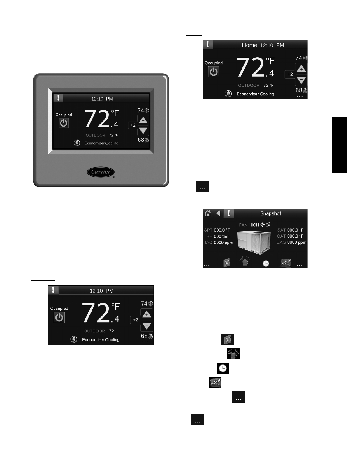
APPENDIX C -- EQUIPMENT TOUCH NAVIGATION SCREENS
Equipment Touch is a touchscreen device with a 4.3 in.
Color LCD display that can be connected to the RTU
Open controller to view or change its property values,
schedule equipment, view trends and alarms, and more,
without having to access the Building Automation
system’s server.
C14132
Fig. 20 -- Equipment Touch
Home
Displays:
S space temperature
S current setpoints
S mode
S occupancy
S OAT, if available
Allows:
S Pushbotton Override
S Space Setpoint Offset Adjustment
Tap
on the right to navigate to the Snapshot screen.
Snapshot
C14134
48---50LHTCQ---01T
This appendix provides a brief overview of the screens used
to navigate the Equipment Touch. For full details on
installation and setup refer to the Equipment Touch
Installation and Setup Guide (Catalog No. 11--808--443--01
or later).
NOTE: The System Touch when connected to the RTU
Open controller over the BACnet MS/TP network will
provide the same screens and function as the Equipment
Touch.
Standby
C14133
The Standby screen displays after the Inactivity Timer
expires (default is 5 minutes).
Displays:
S space temperature
S current setpoints
S mode
S occupancy
S OAT, if available
The Standby screen is not interactive. Touch anywhere on
the screen to advance to the Home screen.
C14135
Displays:
S SAT
S RH
S IAQ
S OAQ
S OAT, if available
Navigates to:
S Filter Status
S Alarm History
S Schedules
S Trends
S Back to Home -- on the left
S Forward to the next screen -- RTU Properties Menu --
on the right
45
Page 46

RTU Open Properties
Show/Hide Configuration
Navigates to the Property pages.
Login with one of the following passwords:
S User level -- type user
S Admin level -- type admin
NOTE: Only the buttons that are authorized for a specific
password level are visible.
48---50LHTCQ---01T
C14136
C14137
You can configure Show/Hide conditions for values on the
following screens:
S Standby
S Home
S Snapshot
NOTE: Only shown when logged in with the admin
password. (See note above.)
46
Page 47

48---50LHTCQ---01T
47
Page 48

48---50LHTCQ---01T
Copyright 2014 Carrier Corp. D 7310 W. Morris St. D Indianapolis, IN 46231 Edition Date: 05/14
Manufacturer reserves the right to change, at any time, specifications and designs without notice and without obligations.
48
Catalog No: 48 --- 50LHTCQ--- 01T
R e p l a c e s : 4 8 --- 5 0 L C --- 7 --- 2 6 --- 2 T / 4 8 --- 5 0 H C T Q --- 0 2 T
Page 49
RTUOPENSTART--UPSHEET
RTU Model Number: Date:
RTU Serial Number:
Performed by:
RTU Open Software Version: Company:
Protocol and Baud Rate: Network Address:
CONFIGURATION POINTS
POINT NAME BACnet Object RANGE DEFAULT ENTRY
SETPOINT
Occupied H eating Setpoint occupied_heat_setpoint 40-90 °F 70
Occupied C ooling Setpoint occupied_cool_setpoint 55-99 °F 76
Unoccupied H eating Setpoint unoccupied_heat_setpoint 40-90 °F 55
Unoccupied C ooling Setpoint unoccupied_cool_set point 45-99 °F 90
Effect ive Heat Set point effective_heat _setpoint 0-120 ° F
Effect ive Cool Set point effecti ve_cool_setpoint 0- 120 °F
Optimal Start optm_start 0-4 hr 1
Optimal Start Type start_type 1=None
Heat St art K fact or (min/deg) h_kfactor 0- 99 15
Cool S tart K fact or (min/deg) c_kfactor 0-99 15
Occ Rel ative Humidit y Setpoint occ_dehum_stpt 0-unocc setpoi nt %rh 60
Unocc Rel ative Humidi ty Setpoint unocc_dehum_stpt 30-100 %r h 95
DCV M ax Ctrl Set point iaq_stpt _max 0-9999 ppm 650
Power E xhaust Setpoint
Occupied A larm Hysteresi s occ_spt_alrm_hyst 0-20°F 5
Alarm D elay (min/deg) spt_alrm_del ay 0-60 minutes 10
Unoccupied Low SPT Al arm Limit uno_spt_alrm_l o_lmt 35-90 °F 45
Unoccupied H igh SPT A larm Limit uno_spt_alrm _hi_lmt 45- 100 °F 95
Low SAT Alarm Limit sat _lo_alrm_lim 15-90 °F 38
High SAT AlarmLimit sat_hi_al rm_lim 90-175 ° F 160
Occupied H igh RH Alar m Limit ( %RH) sprh_hi_alrm_lim 0-100%rh 70%rh
Alarm D elay (min/%RH ) spr h_delay 0-30 mi n 5min
Unoccupied H igh RH Al arm Limit ( %RH) unocc_sprh_lmt 0-100%rh 100%rh
Low RH A larm Limit (%RH) sprh_l o_alrm_lim 0-100%rh 30%rh
Occupied H igh CO2 Alar m Limit ( ppm) i aq_occ_hi_lmt 0-9999 ppm 1200
1
= This point is hidden from view when Continuous Occupied Exhaust is enabled
1
pexh_stpt 20-90 %O pen 50
2=Temp C ompensated
3=Learning A daptive
SPACE TEMPERATURE ALARM
SUPPLY TEMPERATURE ALARM
SPACE HUMIDITY ALARM
IAQ / VENTILATION ALARM
Temperatur e Compensated
48---50LHTCQ---01T
49
Page 50

48---50LHTCQ---01T
CONFIGURATION POINTS (CON’T)
POINT NAME BACnet Object RANGE DEFAULT ENTRY
UNIT CONFIGURATION
Fan Mode fan_mode 1=Auto
Power F ail Restart Delay start_del ay 0-30 sec 5
Fan OffDelay fan_delay_of f 0-180 sec 90
Minimum Cooling SAT sat_cl_min 45-75_F 50
Maximum Heating SAT sat_ht_max 85-150_F 120
Vent Dm pr Pos / DC V Min Pos econ_min 0-100% O pen 20
Economizer P urge Min Pos econ_purge_mi n 0-100% Open 40
LowFanEconMinPos
DCV M ax Vent Damper P os iaq_dpr _max 0-75% Open 50
S Fan Service AlarmTimer sfan_ser vice_hrs 0-9999 hr 600
Supply F an Service Al arm Timer sfan_servi ce_hrs 0- 9999 hr 600
Comp 1 S ervice Alarm T imer comp1_service_hr s 0-9999 hr 0
Comp 2 S ervice Alarm T imer comp2_service_hr s 0-9999 hr 0
Filter Service Alarm Timer f ilter_service_hr s 0-9999 hr 600
Door Al arm Delay door_alarm_del ay 0-180 sec 60
Pushbutton Over ride pb_enable Disable/ Enable E nable
Setpoint Adjustment stpt_adj _enable Disabl e/Enable E nable
Setpoint Adjustment Range stpt_adj_range +/-0-5_F 5
Cooling Lockout Temperatur e oat_cl _lockout 0-80_F 45
Economizer H igh OAT Lockout Temp oat_ec _lockout 55-80_F 75
HP Rev C ycle Lockout Temp
HP Aux Heat Lockout T emp
Heating Lockout Temperatur e oat_ht_lockout 35-150_F 65
Pre Occupanc y Purge preocc_purge Disable/ Enable Di sable
Purge Time purge_time 0-240 m in 60 mi n
Unocc Fr ee Cool ntfc_ena Disabl e/Enable Disable
Min Set point Separati on min_stpt_sep 2-10_F 5
Occupancy Sour ce occ_source 1=Alw ays Occupied
2
= This point is only visible when Fan Control is configured for Two Speed
3
= This point is only visible when Uni t Type is configured for HP O/B Ctrl or HP Y 1/W1 Ctrl
2
3
3
econ_min_2 0-100% Open 33
hp_rev_cycle_lockout -20-65_F -3
oat_auxht_lockout - 20-65_F 40
2=Continuous
3=Always On
2=BACnet Schedule
3=BAS on/ off
4=Remote O cc Input
Continuous
Always O ccupied
50
Page 51

CONFIGURATION POINTS (CON’T)
POINT NAME BACnet Object RANGE DEFAULT ENTRY
Input 1 F unction ai1_funct ion 1=No S ensor
Input 2 F unction ai2_funct ion 1=No S ensor
Input 3 F unction di3_funct ion 1=No F unction
Input 3 Sw itch Configur ation di 3_type N/O
Input 5 F unction di5_funct ion 1=No F unction
Input 5 Sw itch Configur ation di 5_type N/O
Input 8 F unction di8_funct ion 1=No F unction
Input 8 Sw itch Configur ation di 8_type N/O
Input 9 F unction di9_funct ion 1=No F unction
Input 9 Sw itch Configur ation di 9_type N/O
Space sensor t ype spt_type 1=T55
ZS S ensor Binder zs_binder Rnet /Unused Rnet
ZS ZoneTemp zs_zone_temp Zone Temp(1-5) Main ZS S ensor
ZS Z one Humidity zs_zone_humidi ty Z one Humidity ( 1-5) Main ZS Sensor
ZS ZoneCO2 zs_zone_co2 Zone CO2 ( 1-5) Mai n ZS Sensor
Space Tem perature lcl _space_temp
Space Tem p Calibration spt_offset -9.9-10°F 0
Space RH lcl_space_rh 0-100%
Space AQ lcl_space_aq 0- 5000ppm
Supply A ir Temperatur e lcl _sa_temp -56-245° F
Supply A ir Temp Cal ibration sat_offset -9.9-10°F 0
Outdoor A ir Temperatur e lc_oa_temp -56-245°F
Outdoor A ir Temp Cal ibration oat_of fset -9.9-10°F 0
INPUT CONFIGURATION
2=IAO S ensor
3=OAQ S ensor
4=Space RH Sensor
2=IAO S ensor
3=OAQ S ensor
4=Space RH Sensor
2=Compressor S afety
3=Fan Status
4=Fil ter Status
5=Remote O ccupancy
6=Door C ontact
N/C
2=Fire S hutdown
3=Fan Status
4=Fil ter Status
5=Remote O ccupancy
6=Door C ontact
N/C
2=Enthalpy S witch
3=Fan Status
4=Fil ter Status
5=Remote O ccupancy
6=Door C ontact
N/C
2=Humidi stat
3=Fan Status
4=Fil ter Status
5=Remote O ccupancy
6=Door C ontact
7=IGC Over ride
N/C
2=T56 (use f or T59)
3=SPT S ensor
4=None
5=ZS S ensor
SENSOR CALIBRATION
IAQ S ensor
No Sensor
Compressor Safety
N/O
Fire S hutdown
N/C
Enthalpy S witch
N/O
Humidis tat
IGC Override (48 Series LC
WeatherExpert units)
N/O
None
48---50LHTCQ---01T
51
Page 52

48---50LHTCQ---01T
CONFIGURATION POINTS (CON’T)
POINT NAME BACnet Object RANGE DEFAULT EN TRY
Unit Type unit _type 1=Heat/C ool
Compressor S tages
Face Split Coil
Economizer E xists econ_exist No/Yes No (No FIOP)
Fan Cont rol
VFD I nput vfd_in_type 0-10Vdc/ 2-10Vdc 2-10Vdc
Max VF D Output max_vf d_spd 33-100% 100%
Min VF D Output min_vfd_spd 15- 100% 40%
Dehum Mi n VFD Output dehum_m in_vfd 50-100% 60%
Reversing V alve Output
Heat T ype heat _type Electric/Gas Gas (48 Ser ies Units)
Number of Heat St ages heat_stages 1= 1 stage
Continuous Oc cupied Exhaust occ_exh No/Yes No
RH Control rh_enable Disabl e/Enable Enable (U nits with H umidi-MiZerR)
DCV Control dcv_enable Disable/ Enable Disable
Indoor CO 2 Sensor Value @ M in mA iaq_ref _lo_ppm 0-9999ppm 0
Indoor CO 2 Sensor Value @ M ax mA i aq_ref_hi_ppm 0- 9999ppm 2000
Outdoor C O2 Sensor Value @ Min mA oaq_ref_lo_ppm 0-9999ppm 0
Outdoor C O2 Sensor Value @ Max mA oaq_ref_hi _ppm 0-9999ppm 2000
System S pace Temperature system_spt
System S pace RH system_rh
System S pace AQ system_iaq
System O utdoor AQ system_oaq
System C ool Demand Level cool_demand_level 0-3 0
System H eat Demand Level heat_dem and_level 0-3 0
System O utdoor Air T emperature system_oat
Economizer H igh OAT Lockout Temp oat_ec_lockout 55-80_F 75
Vent Dm pr Pos / DC V Min Pos econ_mi n 0-100% Open 20
Economizer P urge Min Pos econ_purge_min 0-100% Open 40
LowFanEconMinPos econ_mi n_2 0-100% Open 33
DCV M ax Vent Damper P os iaq_dpr_max 0-75% Open 50
HP Rev C ycle Lockout Temp hp_rev_cycle_lockout -20-30_F -3
Occupancy Sour ce occ_source 1=A lways Occupied
ServiceTest test _enable Di sable/Enable Disabl e
Fan Test fan_test Disable/ Enable Disable
High S peed Fan Test hi_spd_test D isable/Enable Dis able
Compressor 1 Test com p1_test D isable/Enable Dis able
Compressor 2 Test com p2_test D isable/Enable Dis able
Heat 1 T est heat1_test Disable/Enabl e Di sable
Heat 2 T est heat2_test Disable/Enabl e Di sable
Reversing Valve T est rev_vlv_test Di sable/Enable Dis able
Dehumidif ication Test dehum_test Di sable/Enable Disabl e
Power E xhaust Test pexh_test Disable/E nable D isable
Economizer T est econ_test 0-100 %O pen 0
VFD S peed Test vf d_spd_test 0-100% 0
4
= This point is visible when Fan Control is configured for Variable Speed and not LC WeatherExpert
5
= This point is visible when Unit Type is confi gured for HP O/B Ctrl
6
= These points are not visible when uni t type is configured for LC WeatherExpert
4
4, 6
6
5
comp_stages 1=One S tage
face_split Yes/No No
fan_type 1= Single Speed
rev_vlv_type O output type/B out put type O output ty pe
SERVICE CONFIGURATION
2=LC Weather Expert
3=HP O /B Ctrl
4=HP Y1/W1 Ctrl
2=Two S tages
2=Two S peed
3=Variabl e Speed
2=2 stages
3=0 stage
2=BACnet Schedule
3=BAS On/Off
4=Remote O cc Input
SERVICE TEST
Heat/Cool (TC/ HC models, and LC s izes 04-06))
LC WeatherE xpert (LC si zes 07-26)
HP Y1/ W1 Cltl ( TCQ and HCQ models)
One Stage ( sizes 04-07, and A 08-A12)
Two S tages (TC/HC sizes 08-30 and LC s izes
04-06)
Three S tages (LC WeatherE Xpert sizes 07- 26)
Yes (FIOP)
Single S peed (04-07 and A08-12)
Two S peed (units wit h SAV™ option)
Variabl e (LC WeatherExper t sizes 07-26)
Electr ic (50 Seri es Units)
0 ( 50 series cooli ng only units)
1 (All TCQs and HCQs,
Low Nox uni ts, single phase
gas units, TC04-09 l ow and
TC05-07 m ed heat 3 phase
gas units)
2 ( TC 04 and 08-09 med,
TC05-09 hi gh heat 3 phase
gas units, HC04-09 3 phase
gas units and al l 12-20 gas
units, i ncluding all LC uni ts)
Disable ( Units w/o H umidi-MiZerR)
Always O ccupied
Copyright 2014 Carrier Corp. D 7310 W. Morris St. D Indianapolis, IN 46231 Edition Date: 05/14
Manufacturer reserves the right to change, at any time, specifications and designs without notice and without obligations.
52
Catalog No: 48 --- 50LHTCQ--- 01T
R e p l a c e s : 4 8 --- 5 0 L C --- 7 --- 2 6 --- 2 T / 4 8 --- 5 0 H C T Q --- 0 2 T
 Loading...