

Page 1
!
WARNING: Cancer - www.P65Warnings.ca.gov
Variable Air Volume Terminals
Installation, Start-Up and
Service Instructions
45J,K,M,N,Q,R
Fan Powered
CONTENTS
SAFETY CONSIDERATIONS . . . . . . . . . . . . . . . . . . . . . .1
PRE-INSTALLATION . . . . . . . . . . . . . . . . . . . . . . . . . . . . . .1
General . . . . . . . . . . . . . . . . . . . . . . . . . . . . . . . . . . . . . . . . . . .1
Unit Identification. . . . . . . . . . . . . . . . . . . . . . . . . . . . . . . . .2
Warranty. . . . . . . . . . . . . . . . . . . . . . . . . . . . . . . . . . . . . . . . . .3
CONTROL OPTIONS . . . . . . . . . . . . . . . . . . . . . . . . . . .4
VAV CCN Controls and OPEN VAV Controls . . . . .4
®
VVT
CCN Controls and OPEN VVT Controls . . . . .4
Analog Electric Controls. . . . . . . . . . . . . . . . . . . . . . . .4
Pneumatic Controls . . . . . . . . . . . . . . . . . . . . . . . . . . . .4
Direct Digital Controls (By Others). . . . . . . . . . . . . . . .4
No Control Units . . . . . . . . . . . . . . . . . . . . . . . . . . . . . . .4
INSTALLATION . . . . . . . . . . . . . . . . . . . . . . . . . . . . . . . . . . .4
Step 1 — Install Fan-Powered Box . . . . . . . . . . . . . . . .4
Step 2 — Make Duct Connections . . . . . . . . . . . . . . . .5
Step 3 — Connect Power Wiring . . . . . . . . . . . . . . . . . . 5
Step 4 — Set Up System and Calibrate. . . . . . . . . . . .7
START-UP . . . . . . . . . . . . . . . . . . . . . . . . . . . . . . . . . . . . . . . .8
General . . . . . . . . . . . . . . . . . . . . . . . . . . . . . . . . . . . . . . . . . . .8
Initial Start-Up Procedures. . . . . . . . . . . . . . . . . . . . . . . .8
Balancing Carrier Fan Terminals. . . . . . . . . . . . . . . . . .9
Speed Controller. . . . . . . . . . . . . . . . . . . . . . . . . . . . . . . . .16
Setting Fan Air Flow with ECM Motors . . . . . . . . . . .16
PNEUMATIC CONTROLS . . . . . . . . . . . . . . . . . . . . . .17
General — Single Function Pneumatic Controller
Control Sequences (1300-1305, 1400-1401) . . . .17
Units with Single-Function Controllers . . . . . . . . . .17
Units with Multi-Function Controllers
(Sequences 1306-1317 and 1402-1405) . . . . . . . .18
Operation Sequences. . . . . . . . . . . . . . . . . . . . . . . . . . . .19
Analog Controls Installation and Balancing
Procedures . . . . . . . . . . . . . . . . . . . . . . . . . . . . . . . . . . . . . .19
Thermostat Installation . . . . . . . . . . . . . . . . . . . . . . . . . .20
Programming Thermostat . . . . . . . . . . . . . . . . . . . . . . .20
SERVICE . . . . . . . . . . . . . . . . . . . . . . . . . . . . . . . . . . . . .22
Controls . . . . . . . . . . . . . . . . . . . . . . . . . . . . . . . . . . . . . . . . .22
Fan Motor and Wheel . . . . . . . . . . . . . . . . . . . . . . . . . . . .22
Fan Motor Wiring . . . . . . . . . . . . . . . . . . . . . . . . . . . . . . . .22
Fan Motor Maintenance. . . . . . . . . . . . . . . . . . . . . . . . . .22
SAFETY CONSIDERATIONS
SAFETY NOTE
Air-handling equipment will provide safe and reliable
service when operated within design specifications.
The equipment should be operated and serviced only
by authorized personnel who have a thorough knowledge of system operation, safety devices, and emergency procedures.
Good judgment should be used in applying any manufacturer’s instructions to avoid injury to personnel or
damage to equipment and property.
WARNING
Disconnect all power to the unit before performing maintenance or service. Unit may automatically start if power is
not disconnected. Electrical shock and personal injury
could result.
WARNING
If it is necessary to remove and dispose of mercury contactors in electric heat section, follow all local, state, and federal laws regarding disposal of equipment containing
hazardous materials.
See Fig. 1 for the Proposition 65 warning label.
Fig. 1 — Proposition 65 Warning Label
PRE-INSTALLATION
General
The 45J,K,Q constant volume (series) and 45M,N,R variable
volume (parallel) fan powered boxes (see Fig. 2 and 3) can be
equipped to provide pressure independent, variable volume
(VAV). All units can also be equipped with factory-installed
analog electronic, pneumatic, or variable air volume (VAV)
controls. Units are available with factory-installed electric or hot
water heat.
Catalog No. 04-53450003-01 Printed in U.S.A. Form 45-5SI Pg 1 8-18 Replaces: 45-3SI
Manufacturer reserves the right to discontinue, or change at any time, specifications or designs without notice and without incurring obligations.
Page 2
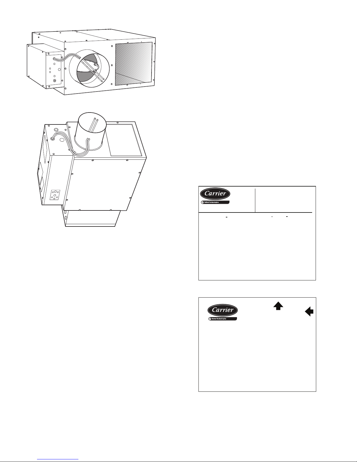
Fig. 2 — Series Flow Unit (45K Shown)
ORDER:
MODEL:
LINE VLT:
STEP:
MIN CIR AMP:
MAX. FUSE OR HACR CIRCUIT BREAKERS
MIN WIRE SIZE (COPPER CONDUCTORS ONLY):
ITEM:
REV: SN:
DUCT SIZE: MIN FPM :
PH: HZ: KW:
AMP:
CTL VOLT: CTL VA:
INTERNAL FUSE
AMP
(SUITABLE FOR AT LEAST 75 DEGREES CENT.)
TAG:
599049
010 C – 599049
– 10
45J 12 X 10 0375
480
03
60 2.50 3.00
01 24 50
5.60 15 AMP 600V
15.00
12AWG
VAV – 05 – 01
DUCT HEATER
AIR
FLOW
UP
not stack uncrated units over 6 ft high. Handle with care. Do
not handle control boxes by tubing connections or other external attachments. Tables 1-7 shows component weights.
INITIAL INSPECTION
Once items have been removed from packing, check careful-
ly for damage to duct connections, coils, or controls. File damage claim immediately with transportation agency and notify
Carrier.
NOTE: Remove all packaging material and foreign material
from unit and ensure the blower wheel moves freely before
installation. Units are shipped with cardboard in both sides of
the fan inlet that MUST be removed.
Unit Identification
Each unit has 2 main labels attached to the casing. The FAN
UNIT label (Fig. 4) lists the model number, supply voltage requirements, motor horsepower and overcurrent protection requirements. The AIRFLOW label (Fig. 5) lists the model number, unit size, factory order number and location. The location
“tag” indicates where the unit is intended for installation. There
may be other labels attached to the unit, as options or codes may
require. Read all labels on a typical unit before attempting installation. Control boxes are assembled as indicated on the identification label.
Contact your local Carrier representative for more in-
formation.
Fig. 3 — Parallel Fan Unit (45J Shown)
The 45J,M units are standard fan powered terminal units. The
45K,N units are quiet fan powered terminal units. The 45Q,R
units are low profile fan powered terminal units.
CONTROL OFFERINGS
Each 45J, 45K, 45M, 45N, 45Q, 45R unit is supplied with a
flow probe as a standard feature. This probe offers a flow averaging capability and results in flow sensing capacity equal to any
competitive unit.
Control options include VAV, VVT, analog electronic, and
pressure-independent pneumatic.
Pneumatic controls are available with linear actuators and
single-function or multi-function controller. The multi-function
controller provides a simple switchover from normally open to
normally closed applications.
Electronic control units feature a factory-installed enclosure
that provides easy access for field connections.
STORAGE AND HANDLING
Inspect for damage upon receipt. Shipping damage claims
should be filed with shipper at time of delivery. Store in a
clean, dry, and covered location. Do not stack units. When
unpacking units, care should be taken that the inlet collars
and externally mounted components do not become damaged.
Do not lift units using collars, sensors, or externally mounted
components as handles. If a unit is supplied with electric or
hot water heat, care should be taken to prevent damage to
these devices. Do not lay uncrated units on end or sides. Do
FAN UNIT
014
45N 5 — 12
MODEL NO
MOTOR
HEAT
FPB—313
TAG:
MOTOR(S) ARE THERMALLY PROTECTED
MIN. SUPPLY CIRCUIT AMPS
MAX. FUSE OR HACR CIRCUIT BREAKERS
MAX. OUTLET AIR TEMPERATURE 200 F
UNIT DESIGNED TO OPERATE AT NO LESS THAN 0.2 IWG STATIC PRESSURE.
ZERO CLEARANCE FROM UNIT, CONNECTED DUCT AND/OR PLENUM
TO COMB USTIBLE MATERIAL.
VOLT
HP
VOLT
KW
277
1/2
480
12.0
21.920
PHASE
PHASE
1
FLA(EA)
3
AMPS
25.000
CODE
HZ
HZHZ
AMPS
60
3.110
60
14.43
REPLACEMENT LINE FUSE
25 AMP 600V
10 579600 C
Fig. 4 — Fan Unit Label
Fig. 5 — Airflow Label
2
REV:
Page 3
INSTALLATION PRECAUTION
Check that construction debris does not enter unit or
ductwork. Do not operate the central-station air-handling fan
without final or construction filters in place. Accumulated dust
and construction debris distributed through the ductwork can adversely affect unit operation.
SERVICE ACCESS
Provide service clearance for unit access (see Installation section on page 4 for details).
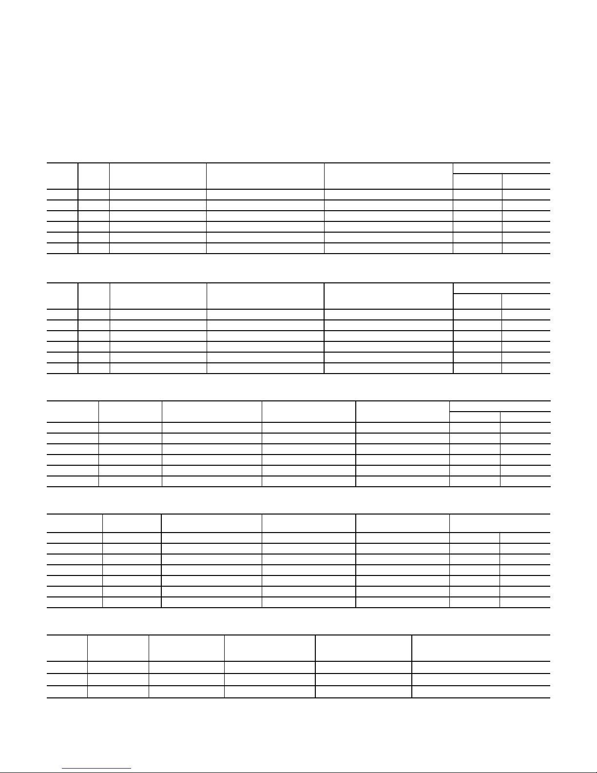
Table 1 — 45J Unit Weights
CODES
Install units in compliance with all applicable code
requirements.
UNIT SUSPENSION
See Installation section on page 4 for unit suspension details.
Warranty
All Carrier-furnished items carry the standard Carrier
warranty.
UNIT
45J
ONLY
SIZE
(lb)
2 70 +4 +9 +30 +19 +21
3 70 +4 +9 +30 +20 +22
4 85 +4 +9 +32 +22 +25
5 85 +4 +9 +32 +24 +28
6 100 +4 +9 +35 +25 +30
7 175 +4 +9 +40 +35 +43
WITH PNEUMATIC
CONTROLS
WITH DDC OR ANALOG
CONTROLS
WITH ELECTRIC HEATER
WITH HOT WATER
1-Row 2-Row
Table 2 — 45M Unit Weights
SIZE
UNIT
ONLY
(lb)
2 114 +4 +9 +30 +19 +21
3 114 +4 +9 +30 +20 +22
4 115 +4 +9 +32 +22 +25
5 122 +4 +9 +32 +24 +28
6 123 +4 +9 +35 +25 +30
7 127 +4 +9 +40 +35 +43
WITH PNEUMATIC
CONTROLS
WITH DDC OR ANALOG
CONTROLS
WITH ELECTRIC HEATER
WITH HOT WATER
1-Row 2-Row
Table 3 — 45K Unit Weights
45K
SIZE
2 185 +4 +9 +30 +9 +12
3 200 +4 +9 +30 +9 +12
4 200 +4 +9 +32 +9 +12
5 225 +4 +9 +32 +12 +17
6 250 +4 +9 +35 +12 +17
7 260 +4 +9 +40 +12 +17
UNIT ONLY (lb)
PNEUMATIC CONTROLS
WITH
WITH DDC OR
ANALOG CONTROLS
WITH
ELECTRIC HEAT
WITH HOT WATER
1-Row 2-Row
45N
SIZE
2 185 +4 +9 +30 +9 +12
3 200 +4 +9 +30 +9 +12
4 200 +4 +9 +32 +9 +12
5 225 +4 +9 +32 +12 +17
6 250 +4 +9 +35 +12 +17
7 260 +4 +9 +40 +12 +17
45Q SIZE UNIT ONLY (lb)
3
4
5
UNIT ONLY (lb)
75 +4 +9 +30 +10/+12
120 +4 +9 +35 +12/+14
100 +4 +9 +35 +12/+14
PNEUMATIC CONTROLS
WITH PNEUMATIC
CONTROLS (lb)
Table 4 — 45N Unit Weights
WITH
Table 5 — 45Q Unit Weights
WITH DDC OR
ANALOG CONTROLS
WITH DDC OR
ANALOG CONTROLS
WITH ELECTRIC HEAT
(lb)
3
WITH
ELECTRIC HEATER
(lb)
WITH HOT WATER
1-Row 2-Row
WITH HOT WATER (1 ROW/2 ROW)
(lb)
Page 4
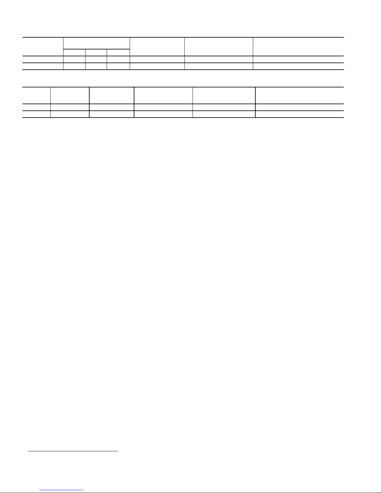
Table 6 — 45Q Dedicated Outdoor-Air System Unit Weights
45Q DOAS BOX
SIZE
3 97 106 120 +9 +30 +10/+12
5 130 145 160 +9 +35 +12/+14
UNIT WITH COOLING
COILS (lb)
2-ROW 4-ROW 6-ROW
WITH DDC OR
ANALOG CONTROLS
(lb)
WITH ELECTRIC HEAT (lb)
WITH HOT WATER (1 ROW/2 ROW)
Table 7 — 45R Unit Weights
45R SIZE UNIT ONLY (lb)
2 91 +4 +9 +25 +8/+10
4 106 +4 +9 +25 +8/+10
LEGEND FOR TABLES 1-7
DDC — Direct Digital Controls
DOAS — Dedicated Outdoor-Air System
WITH
PNEUMATIC
CONTROLS (lb)
CONTROL OPTIONS
The units are offered with a wide variety of factory-mounted
controls that regulate the volume of air delivery from the unit
and respond to cooling and heating load requirements of the conditioned space. All control packages can operate stand-alone and
will fulfill the thermal requirements of a given control space.
These devices are available in both pneumatic and electronic arrangements. The 3V™ and ComfortID™ control types are communicating controls which can be integrated into a CCN building system. A number of DDC (direct digital control) control
packages by others are available for consignment mounting as
indicated.
Control offerings are:
A: Analog Electronic
C: VAV
P: Pneumatic
V: VVT
®
(45M,N,R units only)
N: None or DDC by others
Each control approach offers a variety of operating functions;
a control package number identifies combinations of control
functions. Because of the variety of functions available, circuit
diagrams, operating sequences, and function descriptions are
contained in separate Application Data publications. Refer to the
specific control publication for details.
VAV CCN Controls and OPEN VAV Controls
Pressure independent control packages are available with or
without heat. These controls provide occupied and unoccupied
heating and cooling, demand controlled ventilation (DCV), and
zone humidity control. They can be networked together via either BACnet
provide integrated system operation of all components, including
the operation of air source equipment. These controls may be
used in a stand-alone terminal, or as part of the Carrier DDC
control system. All control arrangements include a standard inlet
1
or Carrier Comfort Network (CCN) protocols to
WITH DDC OR
ANALOG CONTROLS
(lb)
WITH ELECTRIC HEAT
(lb)
WITH HOT WATER (1 ROW/2 ROW)
control enclosure, SCR fan speed controller, 24-volt transformer
and fan relay.
Analog Electronic Controls
Pressure independent control packages are available with or
without hot water or electric heat, automatic or remote night
shutdown, and automatic night setback. All control arrangements include a standard inlet flow sensor, control enclosure,
SCR fan speed controller, 24-volt transformer, fan relay, and
wall thermostat to match the control type.
Pneumatic Controls
Pressure independent control packages are available with or
without hot water or electric heat, night shutdown and/or unoccupied heating. All control arrangements include a standard linear inlet flow sensor and SCR fan speed controller.
Single function controller: Provides single function, i.e., DANO.
Multi-function controller: Capable of providing DA-NO, DANC, RA-NC or RA-NO functions.
Direct Digital Controls (By Others)
Control sequences are available for factory installation of
numerous field-supplied controls from various manufacturers.
All packages include a standard liner inlet flow sensor, control
enclosure, SCR fan speed controller, 24-v transformer, and fan
relay.
Contact Carrier for information on mounting field-supplied
controls.
No Control Units
Control sequences are also available to provide a control box on
units supplied with no factory-installed controls. These arrangements include a standard linear inlet flow sensor, control enclosure, SCR fan speed control, 24-v transformer, and fan relay.
flow sensor, control enclosure, SCR (silicone control rectifier)
fan speed controller, class II 24-volt power transformer, and fan
contactor. Several types of room sensors may be ordered, with
and without set point adjustment, and with integral CO
sensors.
2
VVT® CCN Controls and OPEN VVT Controls
Pressure dependent control packages are available with or without hot water (on-off control), electric heat (up to 2 stages), or
SSR (solid-state relay) electric heat. They are designed to be an
integral part of the Carrier Comfort Network (CCN) or Carrier i-
®
Vu
Open Digital Control Systems, for parallel flow units only.
All control arrangements include a standard inlet flow sensor,
Step 1 — Install Fan-Powered Box
SELECT LOCATION
1. Units should be installed so that they do not come in contact with obstacles such as rigid conduit, sprinkler piping,
Greenfield flexible metal covering, or rigid pneumatic tubing; such contact can transmit vibration to the building
structure, causing objectionable low frequency noise.
2. Units should never be installed tight against concrete slabs
INSTALLATION
or columns, as vibration transmission is amplified in this
condition.
1. BACnet is a registered trademark of ASHRAE (American Society of
Heating Refrigerating and Air Conditioning Engineers).
3. Fan powered terminals require sufficient clearance for servicing the blower/motor assembly from the bottom of the
(lb)
(lb)
4
Page 5

unit, low voltage controls from the side and line voltage
motor controls or electric heat (if equipped) from the rear
(discharge end) of the unit.
Bottom access panel removal requires a minimum of 3-in.
minimum clearance, plus substantial horizontal clearance
to slide the access panel out of the way for service. Actual
horizontal dimensions will vary due to varying access panels for different sized units. See your particular unit’s submittal drawings for more detail.
NOTE: Be certain appropriate accommodations for panel
removal of most unit casings are large enough to allow adequate internal service room once the panels are removed.
A clearance of 18-in. is recommended for control enclosure
access. Unit control enclosure will vary depending on
which control package is used. Control enclosure location
is specified on unit submittals. Low voltage enclosure covers are removable, not hinged.
A clearance of 36-in. is recommended for line voltage motor controls and electric heat control access. High-voltage
motor controls or electric heat control access is supplied
with hinged access doors for units with fused disconnect.
Specific location is indicated on the unit submittal.
NOTE: These recommendations do not supersede NEC
(National Electrical Code) or local codes that may be applicable, which are the responsibility of the installing contractor.
4. Whenever possible, fan-powered boxes should be installed
over halls or passageways (rather than over occupied spaces) in order to limit the sound reaching occupants.
POSITION UNIT
1. When moving boxes, use appropriate material handling
equipment and avoid contact with shaft extensions, controls, wiring, piping, heaters, and control boxes.
2. Raise unit to position using safe mechanical equipment and
support until hanging means are attached and box is level.
INSTALL UNIT
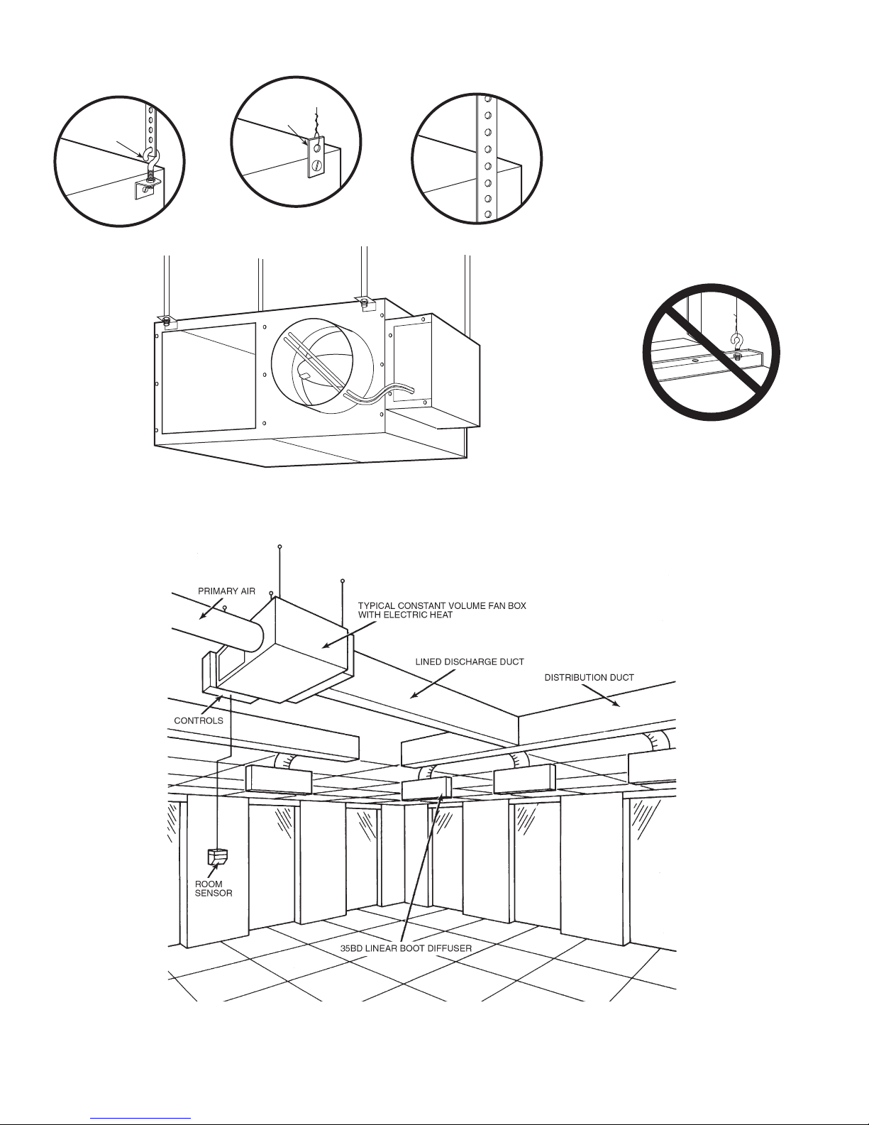
1. Install field-supplied eye bolts, strap hangers or bolt rod
supports as desired. Figure 6 illustrates possible unit suspension methods. A typical installation is shown in Fig. 7.
2. Care should be taken to use hanging materials of sufficient
stiffness and strength, rigidly attached to the unit. Straps
should not be located on coil flanges, electric heat sections,
or control boxes. When using trapeze supports, avoid areas
where access is required to side mounted controls, or side
or bottom access doors. For best installation with trapeze
supports, provide elastomeric material between unit and
supports.
3. Hangers should be securely attached to bar joist or mounting anchors properly secured to building structure with lugs
or poured-in-place hangers. Percussion nails are not considered adequate anchors.
Step 2 — Make Duct Connections
1. Install supply ductwork on each of the unit inlet collars. It
is recommended that 3 duct diameters of straight duct are
supplied to the inlet of the unit. An elbow put at the inlet of
the unit will create turbulence at the inlet making it difficult
for the flow sensor to accurately measure the airflow.
Check that the pressure pick-up in primary air collar is located properly and that air supply duct connections are airtight. Install supply ductwork on unit inlet collar, following
all accepted medium-pressure duct installation procedures.
Seal joints against leakage.
NOTE: For maximum efficiency in controlling radiated noise in
critical applications, inlet ducts should be fabricated of 24-gage
minimum sheet metal in place of flex connections. Flex duct is
extremely transparent to radiated sound; consequently high inlet
statics (Ps) or sharp bends with excessive pressure drop can
cause a radiated noise problem in the space. If flex duct is used,
it should be limited to the connection between the distribution
duct and the boot diffuser.
2. Install the discharge duct. On units with electric heat, the
recommended minimum distance of straight duct before
any transitions, elbows or branch connections is 48 inches.
It is strongly recommended that lined discharge duct be
used downstream of the unit. Insulate duct as required.
3. Fan boxes should not be attached to octopus sections immediately downstream of the unit.
4. Install optional return-air filters before operating the unit.
5. Where construction filters were supplied with the box,
leave filters in place until installation is complete and
building is cleaned for occupancy.
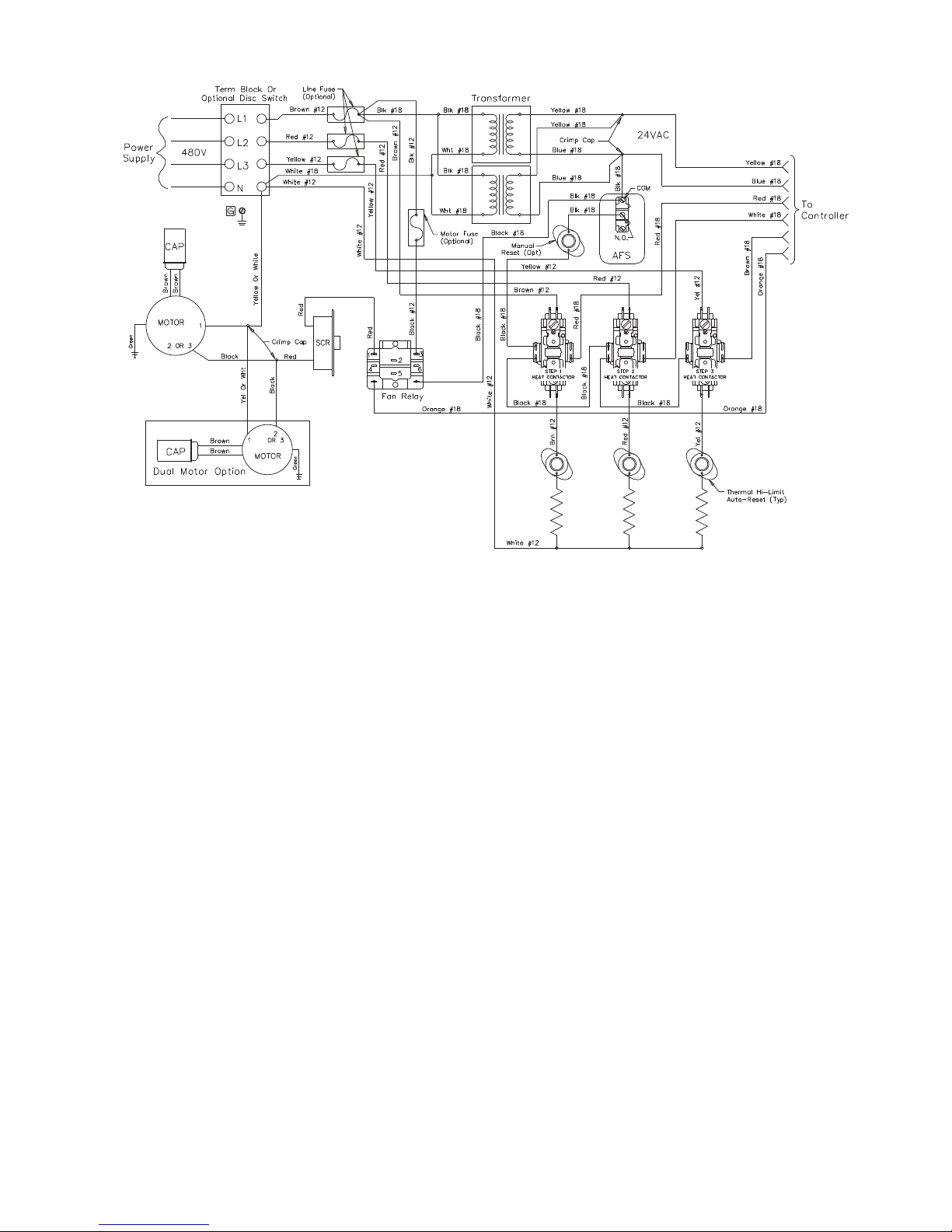
Step 3 — Connect Power Wiring (See Fig. 8)
1. All power wiring must comply with local codes and with
the NEC (National Electrical Code) ANSI/NFPA (American National Standards Institute/National Fire Protection
Association) 70-2017. Disconnect switches are optional
equipment. Electrical, control and piping diagrams are
shown on the exterior labeling or on a diagram inside the
control and high-voltage enclosure covers, unless otherwise specified in the order write-up. All units are wired for
a single point electrical connection to the fan and electric
heater (if equipped). Electric heaters provided by Carrier
are balanced by kW per stage. The installing electrician
should rotate incoming electric service by phase to help
balance overall building load.
2. All field wiring must be provided with a safety disconnect
per NEC 424-19, 20, and 21.
3. Disconnect all incoming power before wiring or servicing
unit. All disconnect switches on the terminal (if equipped)
should be in the OFF position while making power connections.
4. Units with electric heat should use copper wires rated at
least 125% of rating plate amperage. Refer to the unit’s rating label and minimum supply circuit amps.
5. Observe wiring diagram and instructions attached to the
unit. The 480-v, 3-phase units require a Wye power source
with a fourth (neutral) wire in addition to the full sized
ground wire. All units must be grounded as required by
NEC 424-14 and 250.
5
Page 6
FIELD-SUPPLIED
HANGER
BRACKET
OPTIONAL
ACCESSORY
HANGER
FIELD-SUPPLIED
HANGING STRAPS
DO NOT suspend unit
by trapeze hangers
that interfere with the
unit access panel.
Fig. 6 — Typical Unit Suspension Methods (45K Shown)
Fig. 7 — Typical Perimeter Installation — Constant Volume Fan-Powered Box
6
Page 7
LEGEND
AFS — Airflow Switch
CAP — Capacitor
SCR — Silicone Control Rectifier
Fig. 8 — Typical Power Connections for Fan Powered Units with 3-Stage Electric Heat
Step 4 — Set Up System and Calibrate
GENERAL
The parallel fan powered terminals (45M, 45N, and 45R) are
designed to provide varying quantities of cold primary air to a
space in response to a thermostat demand for cooling. For a
heating demand, the fan will operate to supply ceiling plenum
air to the space. For units equipped with a heating coil, the heater
will operate as required to meet a heating demand.
The series fan powered terminals (45J, 45K, and 45Q) are designed to provide a constant airflow to the space. The air supplied to the space is a mixture of primary air and ceiling plenum
air. The fan speed is adjusted to provide the required airflow to
the space. In response to a cooling demand from a thermostat,
the damper will increase the amount of cold primary air while reducing the amount of ceiling plenum air to decrease the temperature of the air being delivered to the space.
Most terminal control packages provide pressure compensation to allow pressure independent operation of the primary air
damper, regardless of changes to the available static pressure in
the supply ductwork. To balance the unit it is necessary to set
both the minimum and maximum airflow set points of the controller. The many types of control options available each have
specific procedures required for balancing. Refer to the submittal
information for these requirements.
SET POINTS
Maximum and minimum airflow set points are normally
specified for the job and specific for each unit on the job. Default
set point values are provided by the factory and can be reset to
the specific requirements in the field. The fan speed must be
field adjusted after all discharge ductwork and diffusers have
been installed.
Field Adjustment of the Maximum and Minimum Airflow
Set Points
Each fan powered terminals unit is equipped with a flow
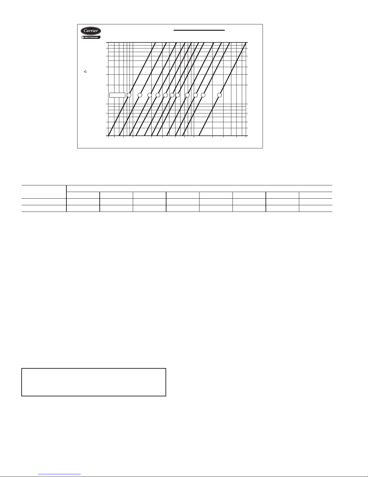
probe installed in the primary air inlet which measures a differential pressure. The relationship between the airflow probe pressure and the corresponding airflow is shown in the Flow Probe
Graph. See Fig. 9. This chart is attached to each unit.
SYSTEM CALIBRATION OF THE INLET AIRFLOW
SENSOR
To achieve efficient pressure independent operation, the velocity sensor and linear averaging flow probe must be calibrated
to the controller. This will ensure that airflow will be accurate for
all terminals at system start-up.
System calibration is accomplished by calculating a flow coefficient that adjusts the pressure fpm characteristics. The flow
coefficient is determined by dividing the flow for a given unit
(design air volume in cfm), at a different velocity pressure of 1.0
in. wg, by the standard pitot tube coefficient of 4005. This ratio
is the same for all sizes, if the standard averaging probe is used.
Carrier inlet areas are shown in Table 8. The design air volume is shown. It can be determined from Table 7 that the average design air velocity for units is equal to 0.2660 fpm at 1.0-in.
wg.
Determine the design air velocity by dividing the design air
volume (the flow at 1.0 in. wg) by the nominal inlet area (sq ft).
This factor is the K factor.
7
Page 8
1.0 (245.5)
.8 (192.0)
.6 (149.3)
(108)
229
INLET AIRFLOW SENSOR
CFM (L/s) @ 1” W.G. SIGNAL
(169)
(243)
(331)
(432)
358
515
(547)
702
916
1160
(676)
1432
(973)
2062
(1324)
2806
(1730)
3665
(3303)
7000
11
9.7
8.2
.4 (99.5)
.3 (74.5)
.2 (49.8)
.1 (24.9)
.07 (17.4)
.05 (12.4)
.04 (10.0)
.03 (7.5)
INLET SIZES 4
40
(19)50(24)70(33)
INLET SENSOR P
INCHES W.G. (PASCALS)
56789101214
100
(47)
(94)
200
300
500
(236)
CFM (L/s)
600
(330)
(142)
1000
(472)
16 22
2000
(944)
3000
(1437)
5000
(2360)
7000
(3303)
6.8
5.8
4.6
3.4
2.6
2.0
1.8
1.4
VOLTS (DC), ANALOG CONTROLS
Fig. 9 — Linear Probe CFM vs Signal Chart
Table 8 — Inlet Areas — 45J,K,M,N,Q,R
INLET DIAMETER (in.)
4568 10 12 14 16
Inlet Area 0.087 ft
2
0.136 ft
2
0.196 ft
2
0.349 ft
2
0.545 ft
2
0.785 ft
2
1.069 ft
2
CFM at 1 in. wg 230 360 515 920 1430 2060 2800 3660
NOTE: For ComfortID™ terminals, all flow sizes are normalized using a single probe multiplier (PMF) for all sizes equal to 2.273.
START-UP
General
Before balancing the system, the air handlers must be operating in accordance with the specifications for air capacity, static
pressure, and temperature. Record data on a unit performance
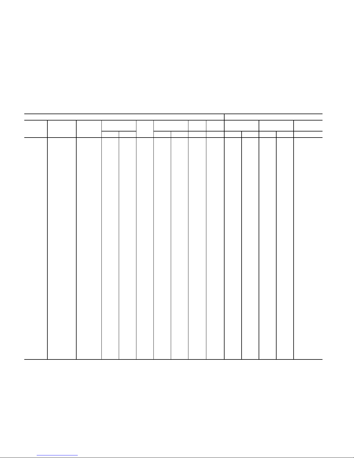
sheet (Fig. 10). The following items must be checked:
1. All fans must be running at calculated and specified rpm.
2. Permanent or temporary filters must be clean and installed
where required.
3. All central station dampers must be adjusted and operating
properly.
4. All thermostats must be calibrated and at the desired settings.
5. All ductwork must be tight.
6. All dirt or loose lining must be removed from inside
ductwork.
7. Pumps and sprays, when used, must be in operation.
8. Connections to the coil, when used, must be checked.
9. Water control valve, if used, must be checked.
IMPORTANT: Before proceeding with start-up, be
certain that voltage, frequency, and phase correspond
to unit specifications. Unless noted, all fan motors are
60 Hz, 115, 208/230, or 277 v, single-phase ac.
Remove the bottom access panel to remove the cardboard
packing material.
Initial Start-Up Procedures
NOTE: The following steps MUST be followed in order to properly operate and service this unit.
1. Disconnect all electrical power to the unit. Failure to disconnect the power to the fan box prior to checking and/or
servicing the fan box could result in a serious injury.
2. Verify that the fan box is installed level, and that adequate
mounting support has been provided.
3. Remove motor access panel from the bottom of the fan
box, and also remove the control panel cover.
4. Test the fan motor setscrew. The setscrew should fit tightly,
but it may have come loose during shipment or installation.
5. Rotate the blower by hand to ensure proper clearance between the blower and the blower housing.
6. Check the fan box for loose fiberglass insulation, especially
on the electric heater elements or the hot water coils (if
these accessories are installed).
7. Check the control enclosure and remove any debris.
8. Check the induction inlet filter (if provided) for obstructions, and verify the filter is securely in place.
9. Verify the main power supply to the connection to the fan
box for proper voltage. If the fan box is installed with electric heat, the electric heat voltage may exceed the blower
NOTE: All 45 Series terminal units are shipped with cardboard
packaging rings placed in one side of the blower housing internal
to the blower/motor. These rings are provided to prevent damage
to the motor during shipment. The rings MUST BE REMOVED
prior to operation. The packing rings are accessible through the
terminal’s plenum. Turn the fan wheel by hand to ensure that
blower is free spinning. Carrier will not accept responsibility for
any additional costs for removal of this packaging material.
motor voltage requirement. Excessive voltage to the fan
box may seriously damage it. Verify that the DDC (if
equipped) are receiving 24-v ac, –15%, +20%.
10. Identify the control system supplied.
11. Check all control connections (and/or electric) for proper
installation.
12. Connect electrical power.
1.369 ft
2
8
Page 9

Balancing Carrier Fan Terminals
Carrier fan terminal units contain primary air dampers
which, under the control of a volume controller, regulate the
amount of cold air distributed to the space.
45J,K,Q SERIES FLOW UNITS
The 45J,K,Q series flow terminals direct all primary air
through the unit fan. The terminal is designed to operate with the
fan supplying airflow equal to or greater than the airflow supplied by the VAV damper. To balance the unit, therefore, it is
necessary to first set the fan flow, and then the VAV damper (primary) flow.
Each control option has specific procedures required for balancing the unit, but some steps are common to all 45J,K,Q units.
The fan box adjustments described below must be made in conjunction with the adjustments described in the Speed Controller
and Control Adjustments section.
The VAV damper airflow may be set at the factory, but the fan
airflow must be set in the field as described in “Setting of VAV
(Primary) Airflow.”
Setting Fan Airflow
NOTE: If the unit has electric heat or hot water heat, temporarily
disable these functions before balancing the fan.
If unit has optional electric heat disconnect downstream of
fan motor connections to power, open disconnect.
If unit does not have optional electric heat disconnect, remove one electric heat power line connection. Be sure to insulate
loose line from ground wire or other wires.
1. Set the controller to provide heating airflow demand only.
Typically, this is accomplished by setting the thermostat to
the highest possible temperature setting.
NOTE: A minimum of 0.1 in. wg downstream static pressure is
required in the duct to ensure proper heater operation.
2. Determine that the VAV valve is fully closed and that the
fan is rotating in the proper direction. (If the VAV damper
is open when the fan is started and there is primary air in
the system, the fan may start and run backward.)
3. Using a flow hood or duct traverse, determine the delivered
fan airflow (cfm).
NOTE: Both flow hood and duct traverse are subject to measurement errors. Be sure that all applicable measurement precautions
are taken.
4. Compare the actual cfm in heating mode to the designed
airflow. If there is a minimum setting for the VAV damper
in heating mode (as recommended by ASHRAE [American Society of Heating, Refrigeration, and Air Conditioning Engineers] Standard 62), this quantity is included in the
total measured heating airflow to determine if the desired
induction airflow level has been met.
5. Adjust the fan SCR at unit control box to achieve the desired airflow rate. Refer to the performance data tables (Tables 9-11) to ensure airflow through electric heaters meets
the requirements before operating the heater.
Setting of VAV (Primary) Airflow
Adjustment of Set Points
Each 45J, 45K, and 45Q supplied with controls is equipped with
a pneumatic or electronic volume controller which regulates the
quantity of cold primary air entering the terminal and the conditioned space. If required airflow levels are specified with the job
order, the minimum and maximum cfm levels will be set at the
factory where applicable. If minimum and maximum levels are
not specified, a default value of 0 is used for minimum setting at
the factory. Other settings of minimum and maximum primary
airflow must be set in the field. Airflow (cfm) ranges for the primary air damper are shown in Tables 9-11. The minimum primary airflow (other than zero) is the minimum flow rate
controllable by the unit volume controller. The primary air
damper can be set at zero for shutoff or at the minimum cfm
listed.
Field Adjustment of Minimum and Maximum Airflow Set
Points
Each 45J, 45K, and 45Q unit is equipped with a centerpoint
averaging flow probe which provides an amplified differential
pressure that is proportional to the unit airflow. Output from this
probe is used to provide a flow signal to both pneumatic and
electronic controls. Unit airflow (cfm) can be read directly from
the flow probe on the unit (refer to Fig. 8).
1. With the unit airflow from the fan set, turn on primary
(VAV) air supply.
2. To set cfm in the field, connect a gage to the flow probe at
the provided ‘T’ taps, and check the differential pressure.
(Alternately, the total flow may be measured, and the previously determined fan induction flow rate may be subtracted
from the total flow to determine VAV flow. However, for
low primary settings, this may not be as accurate as the
flow tap method.)
3. If a minimum VAV flow is required in heating mode, adjust
the volume until the differential pressure corresponds to the
cfm required.
4. Set the controller to provide maximum cooling demand.
This is typically accomplished by first setting the thermostat to the lowest possible temperature setting.
a. In most series fan boxes, the primary airflow rate is
equal to the fan induction flow; in these cases, adjust
the volume controller until a balance is achieved
between fan induced airflow and primary airflow.
When a balance exists, a strip of paper hung at the
induction port should hang straight down, and neither be blown in or out of the unit.
b. If the primary airflow desired is less than the fan
induction flow, adjust the volume controller until the
differential pressure (measured through the flow
probe as described above) corresponds to the cfm
required. Verify that induction exists through the
inlet ports, using the paper strips as described above.
When induction exists, the paper strip should be
pulled into the unit.
5. Return all reheat options to normal connections.
6. Cap the ‘T’ taps.
7. Reset the thermostat to a normal setting.
NOTE: It is normal for the total airflow to the room to increase
slightly in full cooling mode.
9
Page 10
AIR TERMINAL PERFORMANCE SHEET
JOB NAME _________________________________________
JOB LOCATION _____________________________________
CUSTOMER ________________________________________
ENGINEER _________________________________________
BUILDING LOCATION/FLOOR _________________________
BUS NUMBER ______________________________________
CONTROL SET POINTS
Tag
Number
Zone
Address #
Box
Size
(in./cfm)
Cooling
(cfm)
Min Max Min Max Type Btu Min Max Min Max Mult.
Fan
cfm
Heating
(cfm)
Heat kW Occupied Unoccupied
Calibration
Gain
Fig. 10 — Air Terminal Performance Sheet
10
Page 11
Table 9 — 45J Series Fan Powered Terminal Unit Performance
45J WITH PSC FAN MOTOR
UNIT SIZE INLET SIZE (in.)
2 6 100 560 52 or 0 515 1/10 1.8 1 0.7
3
4
5
6
7 16 2100 3900 367 or 0 3665 (2) 3/4 N/A 13.2 9.9
UNIT SIZE INLET SIZE (in.)
3
6
7 16 685 4550 367 or 0 3665 (2) 1 N/A 21.0 13.8
NOTES:
1. 45J maximum primary airflow (cfm) is set by the maximum induced airflow,
which may vary as a function of downstream pressure. Maximum airflow
shown is based on the maximum induced airflow (fan airflow) or 1.00 in.
wg differential pressure signal from inlet airflow sensor, whichever is less.
2. Minimum recommended primary airflow (cfm) is based on 0.03 in. wg differential pressure of the inlet airflow sensor, or 0 airflow. 0.03 in. wg is
equal to 15% to 20% of the nominal flow rating of the terminal. Less than
15% to 20% may result in greater than +5% control of box flow.
3. 45J maximum/minimum fan airflow is based on 0.10 in. wg / 0.60 in. wg
downstream static pressure, respectively.
6
8 92 or 0 916
8
12 206 or 0 1440
10
12 206 or 0 2062
12
14 281 or 0 2530
6
8 92 or 0 916
10
14 281 or 0 2550
FAN AIRFLOW (cfm) PRIMARY AIRFLOW (cfm)
MIN MAX MIN MAX 120V 208/240V 277V
300 990
550 1440
1100 2140
1200 2530
FAN AIRFLOW (cfm) PRIMARY AIRFLOW (cfm)
MIN MAX MIN MAX 120V 208/240V 277V
165 1100
385 2550
52 or 0 515
92 or 0 916
143 or 0 1432
206 or 0 2062
45J WITH ECM FAN MOTOR
52 or 0 515
143 or 0 1432
MOTOR HP
1/4 3.6 2 1.5
1/4 5 2.8 2.110 143 or 0 1432
1/2 8.3 4.6 3.5
3/4 9.5 5.8 4.4
MOTOR HP
1/2 7.7 5.0 4.1
1 12.8 10.5 6.912 206 or 0 2062
MOTOR AMPS
MOTOR AMPS
11
Page 12
Table 10 — 45K Series Fan Powered Terminal Unit Performance
45K WITH PSC FAN MOTOR
UNIT SIZE INLET SIZE (in.)
2
3
4
5
6
7
UNIT SIZE INLET SIZE (in.)
3
6
7
NOTES:
1. 45K maximum primary airflow (cfm) is set by the maximum induced airflow, which may vary as a function of downstream pressure. Maximum airflow shown is based on the maximum induced airflow (fan airflow) or 1.00
in. wg differential pressure signal from inlet airflow sensor, whichever is
less.
2. Minimum recommended primary airflow (cfm) is based on 0.03 in. wg differential pressure of the inlet airflow sensor, or 0 airflow. 0.03 in. wg is
equal to 15% to 20% of the nominal flow rating of the terminal. Less than
15% to 20% may result in greater than +5% control of box flow.
3. 45K maximum/minimum fan airflow is based on 0.10 in. wg / 0.60 in. wg
downstream static pressure, respectively.
6
8 92 or 0 530
6
8 92 or 0 916
10 143 or 0 1100
12 360 or 0 1100
8
12 206 or 0 1300
10
14 281 or 0 1900
10
12 206 or 0 2062
14 281 or 0 2600
16 367 or 0 2600
10
12 206 or 0 2062
14 281 or 0 2806
16 367 or 0 3000
6
8 92 or 0 916
10 143 or 0 1030
12 206 or 0 1030
10
12 206 or 0 2000
14 281 or 0 2000
16 367 or 0 2000
10
12 206 or 0 2062
14 281 or 0 2500
16 367 or 0 2500
FAN AIRFLOW (cfm) PRIMARY AIRFLOW (cfm)
MIN MAX MIN MAX 120V 208/240V 277V
50 530
200 1100
500 1300
800 1900
1200 2600
1250 3000
FAN AIRFLOW (cfm) PRIMARY AIRFLOW (cfm)
MIN MAX MIN MAX 120V 208/240V 277V
250 1030
500 2600
600 2500
52 or 0 515
52 or 0 515
92 or 0 916
143 or 0 1432
143 or 0 1432
143 or 0 1432
45K WITH ECM FAN MOTOR
52 or 0 515
143 or 0 1432
143 or 0 1432
MOTOR
HP
1/10 1.4 0.8 0.6
1/4 4.3 2.4 1.8
1/4 4.3 2.4 1.810 143 or 0 1300
1/2 8.3 4.4 3.512 206 or 0 1900
3/4 9.5 5.0 4.4
1N/A7.1 5.3
MOTOR
HP
1/2 7.7 5.0 4.1
1 12.8 10.5 6.9
1 12.8 10.5 6.9
MOTOR AMPS
MOTOR AMPS
12
Page 13
UNIT
SIZE
3
4
5
UNIT
SIZE
3
4
5
UNIT
SIZE
3
5
Table 11 — 45Q Series Fan Powered Terminal
45Q UNITS WITH PSC FAN MOTOR
INLET
SIZE
(in.)
8
10 143 or 0 1075
10
13.5 X 8 206 or 0 1650
10
14 281 or 0 1970
INLET
SIZE
(in.)
6
10 143 or 0 1100
10
13.5 x 8 206 or 0 1900
8
10 143 or 0 1432
12 206 or 0 1745
14 281 or 0 1745
INLET
SIZE
(in.)
6
8 92 or 0 916
6
10 143 or 0 1432
FAN AIRFLOW PRIMARY AIRFLOW
MIN MAX MIN MAX 120V 208/240V 277V
460 1075
805 1650
840 1970
FAN AIRFLOW PRIMARY AIRFLOW
MIN MAX MIN MAX 120V 208/240V 277V
170 1100
285 1900
265 1745
FAN AIRFLOW PRIMARY AIRFLOW
MIN MAX MIN MAX 120V 208/240V 277V
150 1000
250 1625
92 or 0 916
143 or 0 1432
143 or 0 1432
45Q UNITS WITH ECM FAN MOTOR
52 or 0 515
143 or 0 1432
92 or 0 916
45Q UNITS WITH ECM FAN MOTOR AND DOAS BOX
52 or 0 515
52 or 0 515
MOTOR HP
1/4 5.8 2.6 2.2
(2) 1/6 6.9 3.7 2.7
1/2 8.4 4.2 3.712 206 or 0 1970
MOTOR HP
1/3 5.0 3.3 2.68 92 or 0 916
(2) 1/3 10.0 6.6 5.2
1/2 7.7 5.0 4.1
MOTOR HP
1/3 5.0 3.3 2.6
1/2 7.7 5.0 4.18 92 or 0 916
MOTOR AMPS
MOTOR AMPS
MOTOR AMPS
NOTES:
1. 45Q maximum primary airflow (CFM) is set by the maximum induced airflow, which may vary as a function of downstream pressure. Maximum airflow shown is based on the maximum induced airflow (fan airflow) or 1.00
in. wg differential pressure signal from inlet airflow sensor, whichever is
less.
2. Minimum recommended airflow (CFM) is based on 0.03 in. wg differential
pressure of the inlet airflow sensor, or 0 airflow. 0.03 in. wg is equal to 15%
to 20% of the nominal flow rating of the terminal. Less than 15% to 20%
may result in greater than +5% control of box flow.
3. 45Q maximum/minimum fan airflow is based on 0.10 in. wg / 0.60 in. wg
downstream static pressure, respectively.
13
Page 14

BALANCING 45M,N,R PARALLEL FLOW UNITS
A parallel fan terminal is designed to operate with the fan supplying air equal to 40 to 60% of the VAV damper maximum setting. Adjustments to the parallel units fan should be made with
the primary air closed off. Refer to unit capacity tables to ensure
airflow through the electric heater meets the minimum requirements before operating heater.
Each control option has specific procedures required for balancing the unit, but some steps are common to all parallel fan
units, as described below.
To balance parallel fan unit:
Setting Fan Airflow
NOTE: If the unit has electric heat or hot water heat, temporarily
disable these functions before balancing the fan.
If unit has optional electric heat disconnect downstream of
fan motor connections to power, open disconnect.
If unit does not have optional electric heat disconnect, remove one electric heat power line connection. Be sure to insulate
loose line from ground wire or other wires.
1. Set the controller to provide heating airflow demand only.
Typically, this is accomplished by setting the thermostat to
the highest possible temperature setting.
NOTE: A minimum of 0.1 in. wg downstream static pressure is
required in the duct to ensure proper heater operation.
2. Determine that the VAV damper is fully closed. This may
require a temporary override of the VAV controller. Do not
adjust minimum and maximum cfm set points at this time.
3. Using a flow hood or duct traverse, determine the delivered
fan airflow (cfm).
NOTE: Both flow hood and duct traverse are subject to
measurement errors. Be sure that all applicable measurement precautions are taken.
4. Compare the required design cfm in heating mode to the
actual delivered airflow. If there is a minimum setting for
the VAV damper in heating mode (as recommended by
ASHRAE [American Society of Heating, Refrigeration,
and Air Conditioning Engineers] Standard 62), this quantity is included in the total measured airflow.
5. Adjust the fan SCR at unit control box to achieve the desired airflow rate.
Setting of VAV (Primary) Airflow
Adjustment of Set Points
Each parallel fan unit is equipped with a pneumatic or
electronic volume controller which regulates the quantity of
cold primary air entering the terminal and the conditioned
space. If required airflow levels are specified with the job order, the minimum and maximum cfm levels will be set at the
factory. If minimum and maximum levels are not specified, a
default value is used. Other settings of minimum and maximum primary airflow must be set in the field. Airflow (cfm)
ranges for the primary air damper are shown in Tables 12-14
for 45M,N,R units. The minimum primary airflow (other than
zero) is the minimum flow rate controllable by the unit volume controller. The primary air damper can be set at zero for
shutoff or at the minimum cfm listed.
Field Adjustment of Minimum and Maximum Airflow Set
Points
Each parallel fan unit is equipped with a four quadrant multipoint center averaging flow probe which provides an amplified
differential pressure that is proportional to the unit airflow. Output from this probe is used to provide a flow signal to both pneumatic and electronic controls. Unit airflow (cfm) can be read
directly from the flow probe on the unit.
1. After the unit airflow from the fan has been set, turn on primary (VAV) air supply and turn off the fan.
2. To set cfm in the field, connect a gage to the flow probe
and check the differential pressure.
3. If a minimum VAV flow is required in heating mode, adjust
the volume controller until the differential pressure corresponds to the cfm required.
4. Some control sequences allow the fan to start before the
VAV damper reaches minimum setting, for an overlapping
of fan and VAV flow. For these sequences, after controller
min airflow has been adjusted, the total airflow with both
fan and primary airflow should be checked. For sequences
that call for the fan to start as the first stage of heat, the
cooling minimum cfm can be verified at the diffuser.
Setting the minimum control point will typically require
careful adjustment of the thermostat to create a minimum
cooling demand signal.
5. a. Set the controller to provide maximum cooling de-
mand. This is typically accomplished by setting the
thermostat to the lowest possible temperature setting. For most control sequences, this will cause the
fan to shut off.
b. Adjust the volume controller until the differential
pressure (measured through the flow probe as
described above) corresponds to the cfm required.
6. Return all reheat options to normal connections.
7. Cap the ends of the inlet flow sensors.
8. Reset the thermostat to a normal setting.
14
Page 15
Table 12 — 45M Parallel Fan Powered Terminal Unit Performance
45M WITH PSC FAN MOTOR
UNIT SIZE INLET SIZE (in.)
2
3
4
5
6
7 16 2100 3900 367 or 0 3665 (2) 3/4 N/A 13.2 9.9
NOTES:
1. 45M maximum primary airflow (cfm) is based on 1.00 in. wg differential
pressure signal from inlet airflow sensor.
2. Minimum recommended primary airflow (cfm) is based on 0.03 in. wg differential pressure of the inlet airflow sensor, or 0 airflow. 0.03 in. wg is equal to
6
8 92 or 0 916 1/10 2
6
8 92 or 0 916
8
12 206 or 0 1440
10
12 206 or 0 2062
12
14 281 or 0 2530
FAN AIRFLOW (cfm) PRIMARY AIRFLOW (cfm)
MIN MAX MIN MAX 120V 208/240V 277V
200 400
300 990
550 1440
1100 2140
1200 2530
52 or 0 515 1/10 1.6 0.9 0.7
52 or 0 515
92 or 0 916
143 or 0 1432
206 or 0 2062
15% to 20% of the nominal flow rating of the terminal. Less than 15% to
20% may result in greater than +5% control of box flow.
3. 45M maximum/minimum fan airflow (cfm) is based on 0.25 in. wg external
(downstream) static pressure.
MOTOR HP
1/4 3.6 2 1.5
1/4 5 2.8 2.110 143 or 0 1432
1/2 8.3 4.6 3.5
3/4 9.5 5.8 4.4
MOTOR AMPS
Table 13 — 45N Parallel Fan Powered Terminal Unit
45N WITH PSC FAN MOTOR
UNIT SIZE INLET SIZE (in.)
2
3
4
5
6
7
6
8 92 or 0 916
6
10 143 or 0 1432
6
8 92 or 0 916
10 143 or 0 1432
12 206 or 0 2062
10
14 281 or 0 2806
10
12 206 or 0 2062
14 281 or 0 2806
16 367 or 0 3665
10
12 206 or 0 2062
14 281 or 0 2806
16 367 or 0 3665
FAN AIRFLOW (cfm) PRIMARY AIRFLOW (cfm)
MIN MAX MIN MAX 120V 208/240V 277V
150 530
160 800
190 900
480 1700
500 1700
780 2000
52 or 0 515
52 or 0 515
52 or 0 515
143 or 0 1432
143 or 0 1432
143 or 0 1432
MOTOR
HP
1/10 2.6 1.5 1.1
1/4 3.1 1.7 1.38 92 or 0 916
1/4 3.4 1.9 1.4
1/2 7.3 4.1 3.112 206 or 0 2062
1/2 7.3 4.1 3.1
3/4 9.5 5.8 4.4
MOTOR AMPS
UNIT SIZE INLET SIZE (in.)
6
4
7
NOTES:
1. 45N maximum primary airflow (cfm) is based on 1.00 in wg differential pressure signal from inlet airflow sensor.
2. Minimum recommended primary airflow (cfm) is based on 0.03 in. wg differential pressure of the inlet airflow sensor, or 0 airflow. 0.03 in. wg is equal to
15% to 20% of the nominal flow rating of the terminal. Less than 15% to
20% may result in greater than +5% control of box flow.
8 92 or 0 916
10 143 or 0 1432
12 206 or 0 2062
10
12 206 or 0 2062
14 281 or 0 2806
16 367 or 0 3665
FAN AIRFLOW (cfm) PRIMARY AIRFLOW (cfm)
MIN MAX MIN MAX 120V 208/240V 277V
150 1000
240 1600
45N WITH ECM FAN MOTOR
52 or 0 515
143 or 0 1432
15
MOTOR
HP
1/2 7.7 5.0 4.1
1 12.8 10.5 6.9
MOTOR AMPS
Page 16
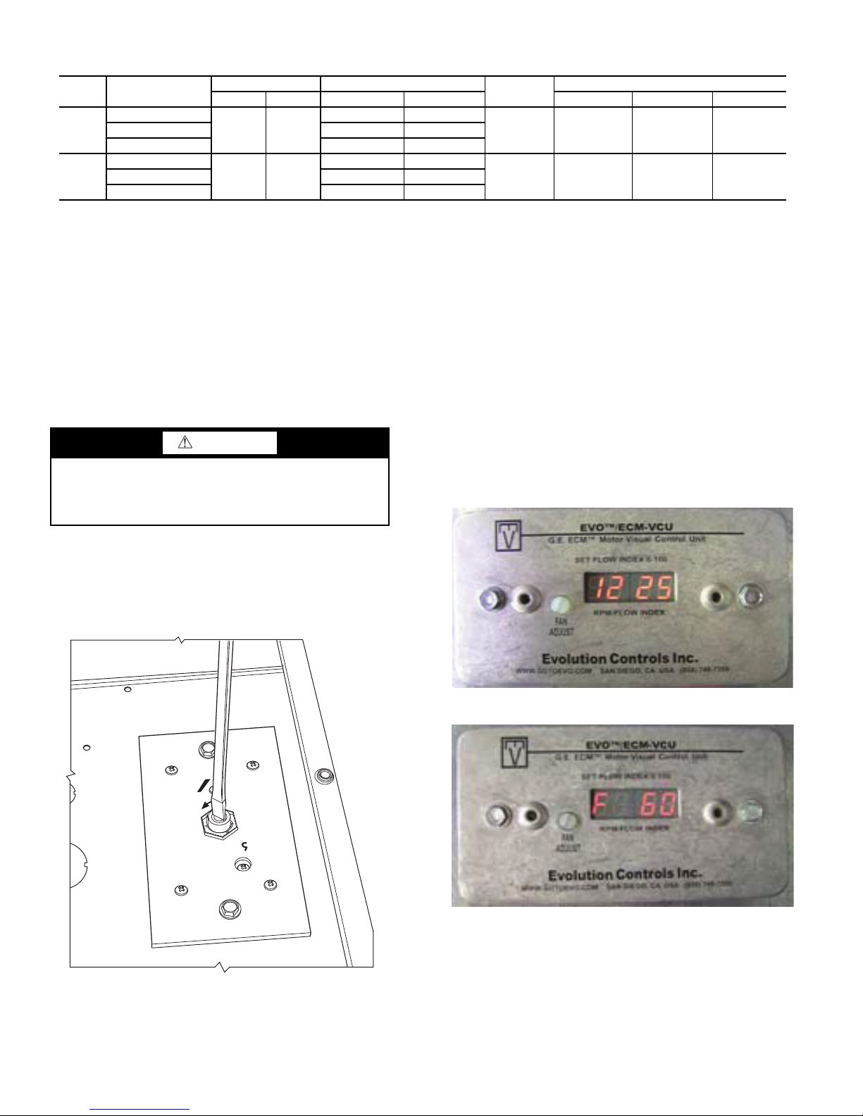
Table 14 — 45R Parallel Fan Powered Terminal Unit With PSC Fan Motor Performance
LO
HI
UR
RANCO
MXF-544002-001
100533-01
277 V 12L
5 FLA
50
6
Z
UNIT
SIZE
NOTES:
1. 45Q maximum primary airflow (CFM) is based on 1.00 in. wg differential
pressure signal from inlet airflow sensor.
2. Minimum recommended airflow (CFM) is based on 0.03 in. wg differential
pressure of the inlet airflow sensor, or 0 airflow. 0.03 in. wg is equal to 15%
INLET SIZE (in.)
6
2
10 143 or 0 1432
8
4
13.5 x 8 206 or 0 2062
FAN AIRFLOW PRIMARY AIRFLOW
MIN MAX MIN # MAX 120V 208/240V 277V
52 or 0 515
350 665
92 or 0 916
420 855
Speed Controller
Each Carrier fan powered air terminal unit is equipped with a
fan SCR speed controller, located on the bottom of the control
box. The SCR can be adjusted in the field.
NOTE: The 45J size 7 unit and 45Q size 4 unit have two SCR
speed controllers, one for each fan. One SCR is located in the
standard position at the bottom of the control box; the other is at
the top of the control box.
The fan airflow output is dependent on the setting of the controller and the downstream static resistance.
CAUTION
The minimum stop on the speed controller is factory set at
an internal minimum stop to prevent damage to the motor.
Do not attempt to override this minimum stop or electrical
damage to the fan motor may result.
MOTOR HP
1/6 3.7 1.5 1.48 92 or 0 916
1/4 5.6 2.5 2.010 143 or 0 1432
to 20% of the nominal flow rating of the terminal. Less than 15% to 20%
may result in greater than +5% control of box flow.
3. 45R maximum/minimum fan airflow is based on 0.25 in. wg external (downstream) static pressure, respectively.
MOTOR AMPS
Setting Fan Air Flow with ECM Motors
Several terminal unit models are available with ECM motors for
easy balancing. These motors supply a determined amount of air
regardless of static pressure from ductwork layout or air distribution. The ECM motors are programmed to provide a maximum CFM depending on model and unit size. The motors are
then set to provide the desired CFM as a proportional amount of
the maximum. The proportion can be set by several options:
VCU (CONTROL OPTION 6)
VCU controlled units are manually operated with a digital readout on the ECM controller (see Fig. 12). The digital readout provides a percent of maximum. A fan adjustment knob is rotated
until the desired percent is displayed. After 20 seconds from
final adjustment, the controller display will alternate between
percent and motor RPMs.
TO INCREASE THE FAN SPEED (RPM), turn the slotted
adjustment on the controller clockwise toward the “HI” marking
printed on the controller face plate (see to Fig. 11).
TO DECREASE THE FAN SPEED (RPM), turn the adjustment
counterclockwise toward the “LO” marking. (see Fig. 11).
Fig. 11 — Fan Speed Controller
Fig. 12 — VCU ECM Controller
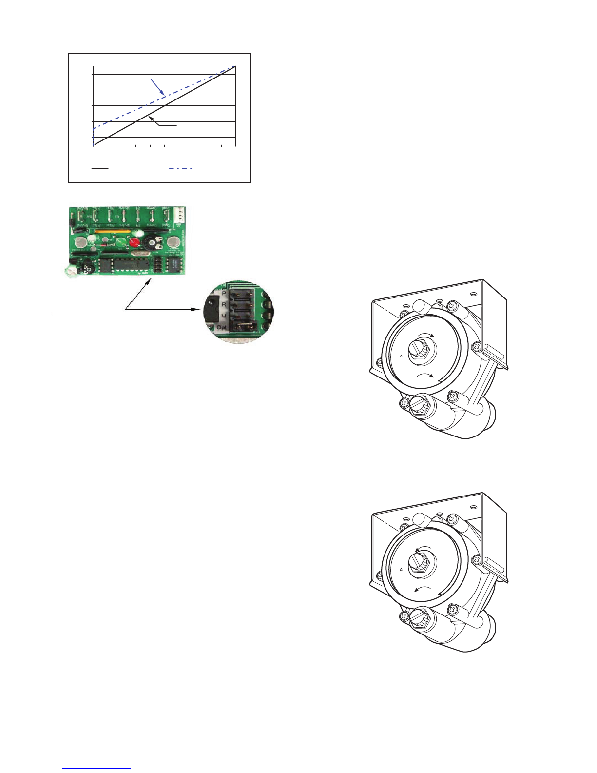
ACU-O, 0-10VDC (0-20MA) INPUT (CONTROL OPTION 7)
The board is factory set to accept a 0-10 Vdc signal to control
the airflow between 0% and 100% as shown in the chart in
Fig. 12. This option does not allow for on/off control. Setting
the jumper to the “Opt” position as shown in the “Jumper
Setting” in Fig. 13 sets the control signal to 0-10Vdc signal.
16
Page 17
3. Check for primary airflow in the inlet duct, using a differ-
NOTE: Both ACU Options provide a manual Override
for field setting the ECM motor without being connected
to a DDC controller. If a DDC controller is connected,
adjusting the manual override with lock out the
automation signal for 15 minutes.
JUMPER SETTING
Volts
0-10Vdc 2-10Vdc with
On/Off
“Opt” Jumper
“P” Jumper
10
9
8
7
6
5
4
3
2
1
0
0 10 20 30 40 50 60 70 80 90 100
Flow Index
HI
LO
CSC-2003
0-1” P
D.A.
DMPR. N.O.
I
N
C
R
E
A
S
E
I
N
C
R
E
A
S
E
HI
LO
CSC-2004
0-1” P
R.A.
DMPR. N.C.
I
N
C
R
E
A
S
E
I
N
C
R
E
A
S
E
ential pressure sensor tapped into the differential pressure
sensor signal line tees.
4. Verify that the installed room thermostat is compatible with
the unit control.
5. Close the primary air damper.
a. RANC — disconnecting the actuator from the con-
troller should allow the damper to close completely.
b. DANO — connecting to 20 psi air supply directly to
the actuator should close the damper completely.
6. Start the blower motor by doing one of the following:
45J,K,Q Units:
Both RANC and DANO — Connect electrical power to
the blower motor control.
45M,N,R Units:
RANC — Connect the main air line to the blower control,
bypassing the thermostat input.
DANO — Disconnect the thermostat line from the blower
controls.
These steps should energize the fan.
ACU-P, 2-10VDC (4-20MA) INPUT (CONTROL OPTION 8)
Another option is to have the board factory set to allow for on/
off control by setting the jumper on to the “P” position. This setting uses a 2-10 Vdc control signal range with a voltage signal
under 2 Vdc turning the motor off. See Fig. 13 for graph of operating range.
General — Single Function Pneumatic Controller
Control Sequences (1300-1305, 1400-1401)
Fig. 13 — ACU ECM Controller
PNEUMATIC CONTROLS
To properly balance the system, all ductwork and outlets must
be installed and connected tightly. Reference piping/wiring diagram on unit for specifics for the control sequence selected for
the unit.
Units with Single-Function Controllers
1. Determine sequence of operations (reverse-acting, normally closed [RANC], direct-acting, normally open [DANO]).
This can be accomplished by reading the diagram affixed
to the unit. The standard RANC controller is gray colored;
the DANO controller is beige. See Fig. 14-16.
2. Check that main air pressure at the controller. Main air
should equal 18 to 25 psi. Main air must be clean and dry.
Fig. 14 — Pneumatic Volume Controller (Normally
Open) for Pneumatic Control Unit (Beige Color)
Fig. 15 — Pneumatic Volume Controller (Normally
Closed) for Pneumatic Control Unit (Gray Color)
17
Page 18
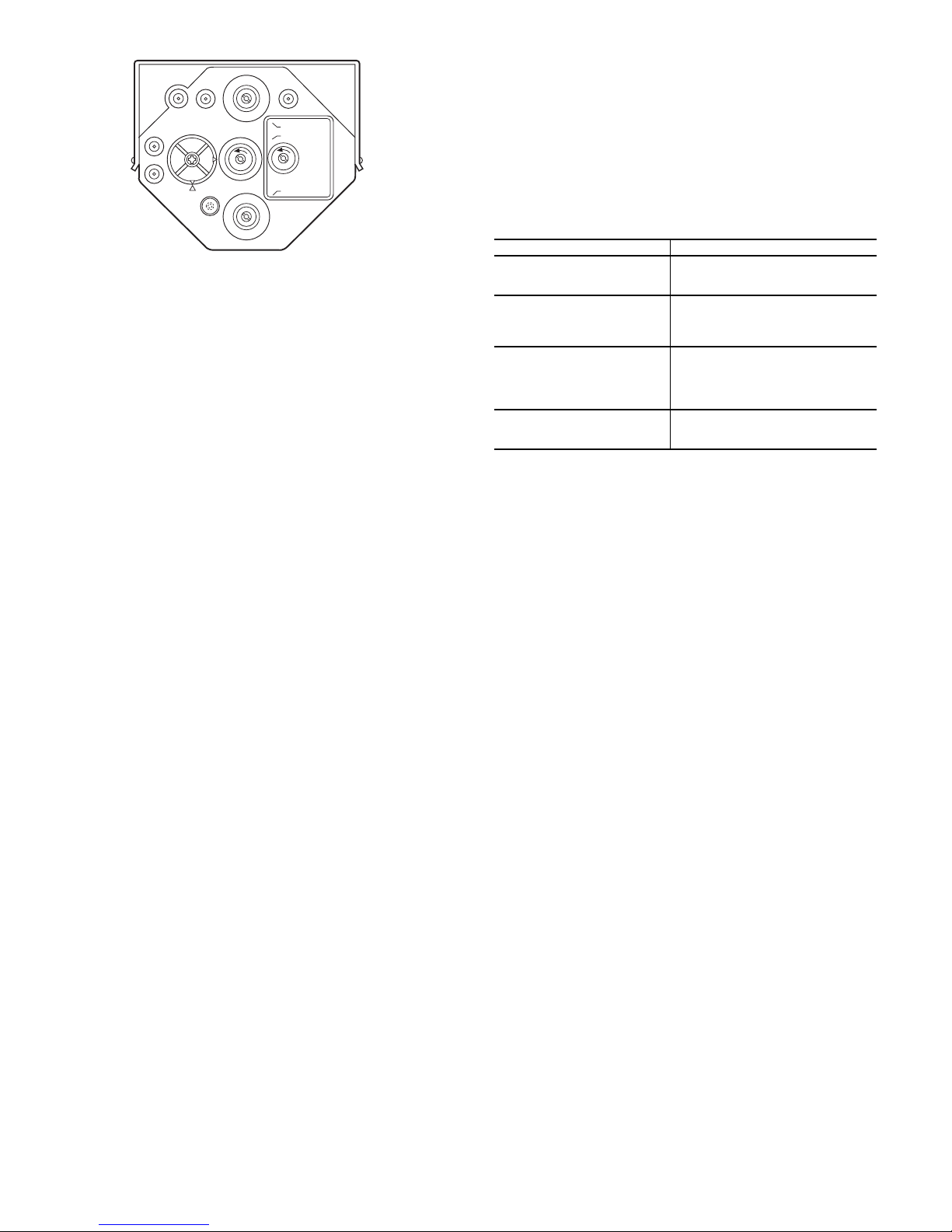
Fig. 16 — CSC 3000 Series Reset Volume Controller
T
H
L
B
M
NO
NC
G
RESET START
LO STAT ΔP
RESET SPAN
HI STAT ΔP
DAMPER
I
N
C
R
I
N
C
R
7. Balance the supply outlets using a proportional air volume
method.
a. With the blower discharging full volume (SCR on
max setting), measure the total air volume.
b. Calculate the percentage of the design air volume
needed by each outlet.
c. Multiply the total air volume by the percent-of-
design air volume for each diffuser.
d. Balance each outlet according to the requirements
calculated above.
8. Balance the unit fan discharge:
a. Measure the total flow discharging from the unit.
b. Adjust the discharge flow from the unit using the unit
electronic speed control (SCR).
9. Reconnect the damper actuator and/or the thermostat tubing to the velocity controller with the fan still running.
Make sure the piping is as shown on the unit piping/wiring
diagram.
10. Balance the primary (cooling) air volume:
NOTE: To balance the primary air side of the 45M,N,R
unit only, the blower motor must be disconnected.
a. Connect the Magnehelic or inclined manometer (0 to
2.0 in. wg scale, maximum) to the differential pressure sensor tubing.
b. Measure the volume of air flowing through the inlet
using the calibration curve affixed to the unit.
RANC
1) With a 0 psi thermostat signal, measure the unit
maximum airflow.
2) Rotate to the “HI” adjustment knob on the velocity
controller, adjust the airflow to the desired maximum setting.
3) With the 15 psig (or greater) thermostat signal,
measure the unit minimum airflow.
DANO
1) At a 0 psi stat signal, measure the unit minimum
airflow.
2) Rotate the “LO” adjustment knob of the velocity
controller, adjust the minimum flow to the desired setting, as read from the differential pressure sensor.
3) With a 15 psig (or greater) thermostat signal, measure the unit maximum airflow.
4) Rotate the “HI” adjustment know on the velocity
controller, adjust the airflow to the desired maximum setting.
11. Reconnect the power to the blower motor on the 45M,N,R
unit.
NOTES:
1. The single function control system uses a KMC CSC 2000
series velocity controller with a rated air consumption of
0.0083 SCFM at 20 psi main air pressure.
2. The maximum and minimum limits are both changed when
adjusting the CENTER knob. For this reason, the center
knob should always be set first.
3. Refer to the Table 15 if any of the above steps do not result
in satisfactory performance.
Table 15 — Troubleshooting Pneumatic Controls
PROBLEM LIKELY CAUSE
Controller does not reset to
maximum minimum set point
during balancing procedure
Controller does not reset to
maximum or point during
operation
Pneumatic actuator does not
stroke fully
Air valve stays in wide open
position
Thermostat signal is being used for
control signal. An artificial signal must
be used.
Thermostat is not demanding minimum set maximum or minimum air
volume. Main air pressure at the controller is less than 15 psi.
Leak in pneumatic tubing between the
controller and the actuator. Main air
pressure at the controller is less that
15 psi. Leak in the actuator diaphragm.
Differential pressure sensor is blocked
or obstructed. Insufficient supply air
pressure in the unit inlet.
Units with Multi-Function Controllers
(Sequences 1306-1317 and 1402-1405)
1. Determine sequence of operation (direct-acting, normally
closed [DANC], reverse-acting, normally closed [RANC],
direct-acting, normally open, or reverse-acting, normally
open). This can be accomplished by reading the diagram
affixed to the unit. All sequences above utilize a four-function controller, allowing for changeover from a given sequence to another.
2. Check the main air pressure at the controller. Main air
should equal 18 to 25 psi. Main air must be clean and dry.
3. Check for primary airflow in the inlet duct, using a differential pressure sensor tapped into the differential pressure
sensor signal line tees.
4. Verify that the installed room thermostat is compatible with
the unit control.
5. Close the primary air damper.
a. DANC, RANC — Disconnecting the actuator from
the controller should allow the damper to close completely.
b. DANO, RANO — Connecting a 20 psi air supply
directly to the actuator should close the damper completely.
6. Start the blower motor by doing one of the following:
45J,K,Q Units:
DANC, RANC, DANO, RANO — Connect electrical
power to the blower motor controls.
45M,N,R Units:
DANC, DANO — Disconnect the thermostat line from the
blower control.
RANC, RANO — Connect the main air line to the blower
control, bypassing the thermostat input.
These steps should energize the fan.
7. Balance the supply outlets using a proportional air volume
method:
a. With the blower discharging full volume (SCR on
max setting), measure the total air volume.
b. Calculate the percentage of the design air volume
needed by each outlet.
c. Multiply the total air volume by the percent-of-
design air volume for each diffuser.
18
Page 19

d. Balance each outlet according to the requirements
calculated in previous steps.
8. Balance the unit fan discharge:
a. Measure the total flow discharging from the unit.
b. Adjust the discharge flow from the unit using the unit
electronic speed control (SCR).
9. Reconnect the damper actuator to the velocity controller
with the fan still running. Make sure the piping is as shown
on the unit piping/wiring diagram.
10. Balance the primary (cooling) air volumes:
NOTE: To balance the primary air side of the 45M,N,R
units only, the blower motor must be disconnected.
a. Connect a Magnehelic or inclined manometer (0 to
2.0 in. wg scale, maximum) to the differential pressure sensor tubing.
b. Measure the volume of air flowing through the inlet
using the calibration curve affixed to the unit.
c. Adjust the “LO STAT” knob, with a 0 psi thermostat
signal, to obtain the desired airflow setting. Depending on the control sequence desired, the “LO STAT”
knob will vary either the minimum setting or the
maximum setting as follows:
DANC — “LO STAT” knob adjusts the minimum
setting.
RANC — “LO STAT” knob adjusts the maximum
setting.
DANO — “LO STAT” knob adjusts the minimum
setting.
RANO — “LO STAT” knob adjusts the maximum
setting.
Operation Sequences
1. During maximum thermostat cooling demand, the primary air damper will open in the maximum airflow setting
providing cold primary air at the preset maximum volume.
Accessory coils, if supplied, are off, and the unit should
discharge primary air only.
2. When the thermostat modulates between maximum cooling and satisfied set point, the primary air damper responds
by proportional settings. Accessory coils, if supplied, are
off. The 45J,K,Q units only will be inducing plenum air
and mixing it with the cold primary air. The 45M,N,R fan
will not induce any plenum air at this point.
3. When the thermostat is modulating between maximum
heating demand and satisfied setpoint, the primary air
damper will be at the minimum air volume setting. A maximum amount of plenum air is induced at this point. In sequence, the first and second stages of electric reheat will
energize, if supplied. If hot water heating coils are supplied,
they will either open fully or modulate open.
4. During thermostat demand for maximum heating, primary
air will flow through the unit at the preset minimum setting, maximum amount of plenum air will be induced, and
heating coils, if supplied, are full on. See Table 15 for
pneumatic control troubleshooting.
5. Adjust the “HI STAT” knob, with a 15 psi thermostat signal, to obtain the desired airflow setting. Depending on
the control sequence desired, the “HI STAT” knob will
vary either the minimum setting or the maximum setting
as follows:
DANC — “HI STAT” knob adjusts the maximum setting
RANC — “HI STAT” knob adjusts the minimum setting
DANO — “HI STAT” knob adjusts the maximum setting
RANO — “HI STAT” knob adjusts the minimum setting
6. To adjust the thermostat reset start point, remove gage port
(“G”) cap and attach a 0 to 30 psi pressure gage and note
the pressure reading. Adjust the thermostat pressure to the
controller, “T” port to the desired start point. Adjust the
“RESET START” knob until the gage pressure begins to
change slightly. Remove pressure gage and replace cap.
7. To adjust the thermostat reset span from standard 5 psi, remove gage port (“G”) cap and attach a 0 to 30 psi pressure
gage and note the pressure reading. Adjust the thermostat
pressure to the controller “T” port to the desired start point.
Adjust the “RESET SPAN” knob until the gage pressure
equals the desired reset span. Remove gage and replace
cap.
8. To change logic from a given sequence to another, follow
the steps below:
a. To change from N.O. to N.C. or from N.C. to N.O.,
loosen the “damper” dial screw and rotate the dial
until the desired damper position indicator is aligned
with the arrow. The VAV damper must be physically
changed to desired position.
b. To change from DA to RA or from RA to DA, no
configuration changes are required — use the appropriate calibration procedures from above.
9. Reconnect the power to the blower motor on the 45M,N
units.
NOTES:
1. The multi-function control system uses a KMC CSC 3000
series velocity controller with a rated air consumption of
1.00 SCFH at 20 psi main air pressure.
2. The maximum and minimum limits are both changed when
adjusting the center knob. The center knob should always
be set first.
Analog Controls Installation and Balancing
Procedures
The Analog Electronic Control System is a pressure independent volume reset control that uses a KMC CSP-4702 controlleractuator (see Fig. 17).
Adjustments for the minimum and maximum airflow settings
are made at the thermostat. The thermostat (CTE-5202) operates
on a 16 VDC power supply from the CSP 4702 controller and
outputs a 0 to 10 VDC signal on the AO1 and AO2 terminals.
AO1 is used as the cooling output and AO2 is used as the heating
output.
19
Page 20
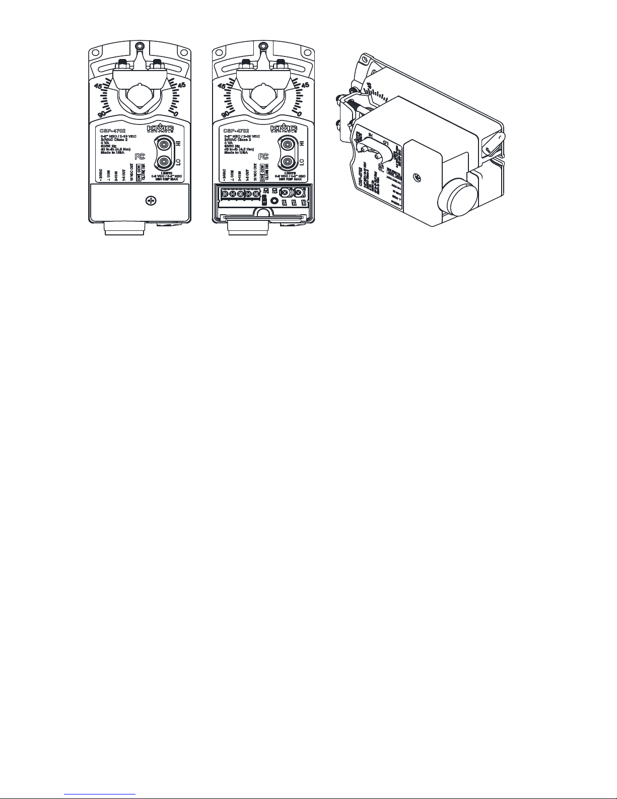
Fig. 17 — CSP-4702 Controller/Actuator
Thermostat Installation
For proper operation, mount the thermostat on an interior
wall. Do not mount the thermostat in a location that will cause it
to be affected by direct sunlight or other heat or cold sources.
The thermostat should be clear of all obstructions so it can properly sense the room temperature. Complete rough-in wiring at
each location prior to thermostat installation. Cable insulation
must meet local building codes.
1. Remove thermostat cover. If the thermostat is locked on the
back plate, turn the two hex screws in on the bottom of the
cover (in the two outermost holes) in the back plate
CLOCKWISE until they clear the cover. Do not remove
these screws completely. Swing the thermostat up and
away from the back plate to remove it.
2. Route the wires through the opening in the back plate.
3. Install the back plate directly to the junction box using the
screws supplied with the thermostat. Verify the hex screws
used for securing the cover are located at the bottom before
installing.
4. Connect the wires to the terminal block. Refer to the wiring
diagram located on the inside cover of the control enclosure of each unit showing the wiring terminations.
5. Replace the thermostat cover. Turn the two hex screws
COUNTER CLOCKWISE until they are flush with the
bottom cover and secure it to the back plate.
Programming Thermostat
1. The thermostat has three sequences that are selectable from
the display screen. To access the configuration menu on the
thermostat, press and hold the Up and Down arrows for 10
seconds until the display starts flashing “LIMITS”. Use the
Up and Down arrows to scroll between the different menu
options or set a specific value. Use the Setpoint button to
select a menu or set a value.
2. To set the minimum and maximum airflow limits, Use
AO1 Min and AO1 Max or AO2 Min and AO2 Max. Use
the Table 16 to determine thermostat setting for the CFM
per inlet size.
3. For details on how to program the thermostat for each
control sequence see the specific control sequence submittal.
20
Page 21
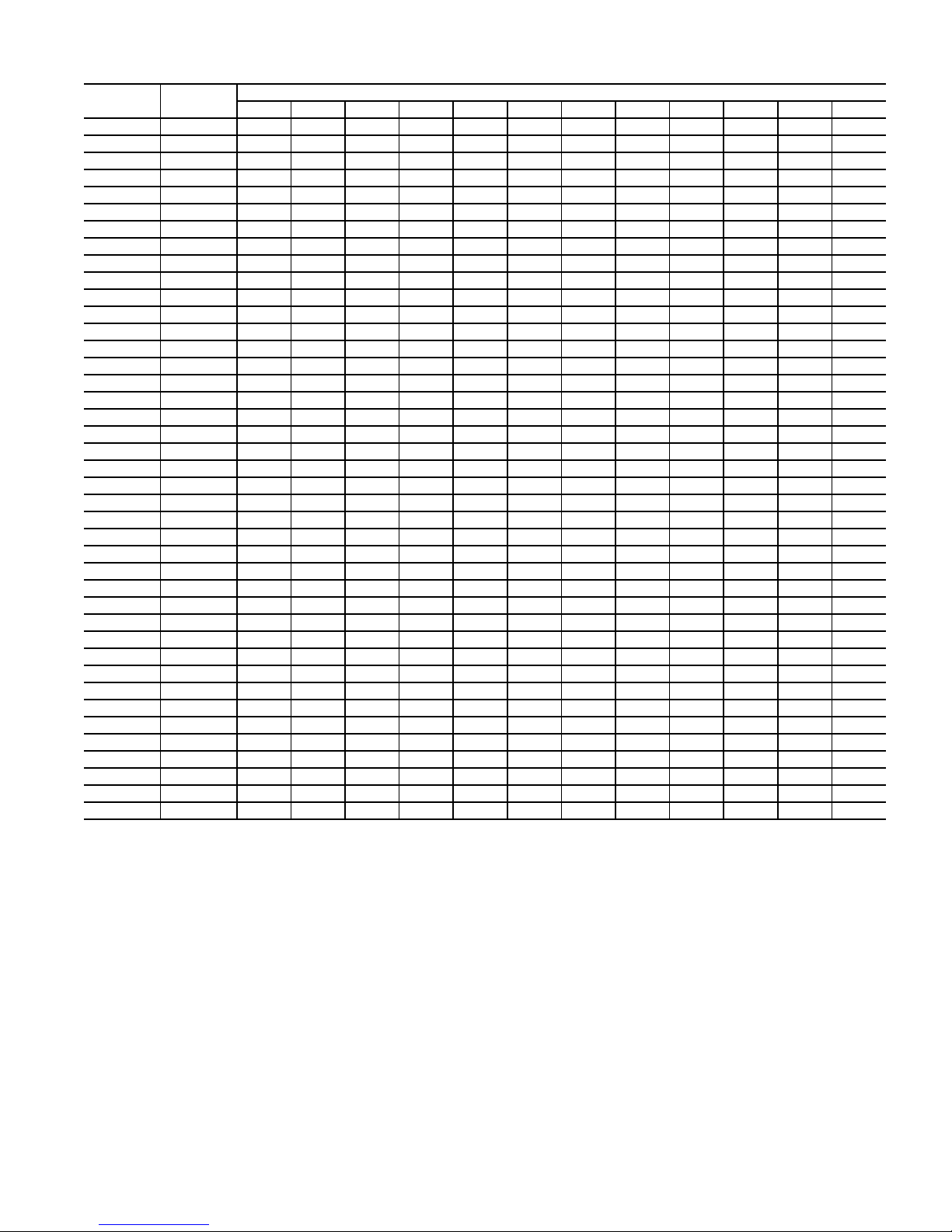
Table 16 — CFM Chart for Setting Minimum and Maximum Values on Thermostat
AO1 AND
AO2
0-2 0.00 00000 0000000
2.1 0.03 36 57 81 111 145 183 226 326 444 580 315 1107
2.2 0.05 51 80 115 157 205 259 320 461 627 820 445 1565
2.3 0.08 63 98 141 192 251 318 392 565 768 1004 545 1917
2.4 0.10 72 113 163 222 290 367 453 652 887 1159 630 2214
2.5 0.13 81 127 182 248 324 410 506 729 992 1296 704 2475
2.6 0.15 89 139 200 272 355 449 555 798 1087 1420 771 2711
2.7 0.18 96 150 216 293 383 485 599 862 1174 1533 833 2928
2.8 0.20 102 160 231 314 410 519 640 922 1255 1639 891 3130
2.9 0.23 109 170 244 333 435 550 679 978 1331 1739 945 3320
3.0 0.25 115 179 258 351 458 580 716 1031 1403 1833 996 3500
3.1 0.28 120 188 270 368 481 608 751 1081 1472 1922 1045 3671
3.2 0.30 125 196 282 384 502 635 784 1129 1537 2008 1091 3834
3.3 0.33 131 204 294 400 522 661 816 1175 1600 2089 1136 3991
3.4 0.35 136 212 305 415 542 686 847 1220 1660 2168 1178 4141
3.5 0.38 140 219 316 430 561 710 877 1263 1718 2244 1220 4287
3.6 0.40 145 226 326 444 580 733 905 1304 1775 2318 1260 4427
3.7 0.43 149 233 336 457 597 756 933 1344 1829 2389 1299 4563
3.8 0.45 154 240 346 471 615 778 960 1383 1882 2459 1336 4696
3.9 0.48 158 247 355 484 632 799 987 1421 1934 2526 1373 4824
4.0 0.50 162 253 364 496 648 820 1012 1458 1984 2592 1408 4950
4.1 0.53 166 259 373 508 664 840 1037 1494 2033 2656 1443 5072
4.2 0.55 170 265 382 520 680 860 1062 1529 2081 2718 1477 5191
4.3 0.58 174 271 391 532 695 879 1086 1563 2128 2779 1510 5308
4.4 0.60 177 277 399 543 710 898 1109 1597 2174 2839 1543 5422
4.5 0.63 181 283 407 555 724 917 1132 1630 2218 2898 1575 5534
4.6 0.65 185 289 416 566 739 935 1154 1662 2262 2955 1606 5644
4.7 0.68 188 294 423 576 753 953 1176 1694 2305 3011 1636 5751
4.8 0.70 192 299 431 587 767 970 1198 1725 2348 3067 1666 5857
4.9 0.73 195 305 439 597 780 987 1219 1755 2389 3121 1696 5960
5.0 0.75 198 310 446 608 794 1004 1240 1785 2430 3174 1725 6062
5.1 0.78 202 315 454 618 807 1021 1260 1815 2470 3227 1753 6162
5.2 0.80 205 320 461 627 820 1037 1281 1844 2510 3278 1782 6261
5.3 0.83 208 325 468 637 832 1053 1300 1873 2549 3329 1809 6358
5.4 0.85 211 330 475 647 845 1069 1320 1901 2587 3379 1836 6454
5.5 0.88 214 335 482 656 857 1085 1339 1929 2625 3428 1863 6548
5.6 0.90 217 340 489 666 869 1100 1358 1956 2662 3477 1890 6641
5.7 0.93 220 344 496 675 881 1115 1377 1983 2699 3525 1916 6732
5.8 0.95 223 349 502 684 893 1130 1395 2009 2735 3572 1941 6823
5.9 0.98 226 353 509 693 905 1145 1414 2036 2771 3619 1967 6912
6.0 1.00 229 358 515 702 916 1160 1432 2062 2806 3665 1992 7000
SENSOR
SIGNAL
4 5 6 7 8 9 10 12 14 16 20 22
CFMs PER INLET SIZE
21
Page 22
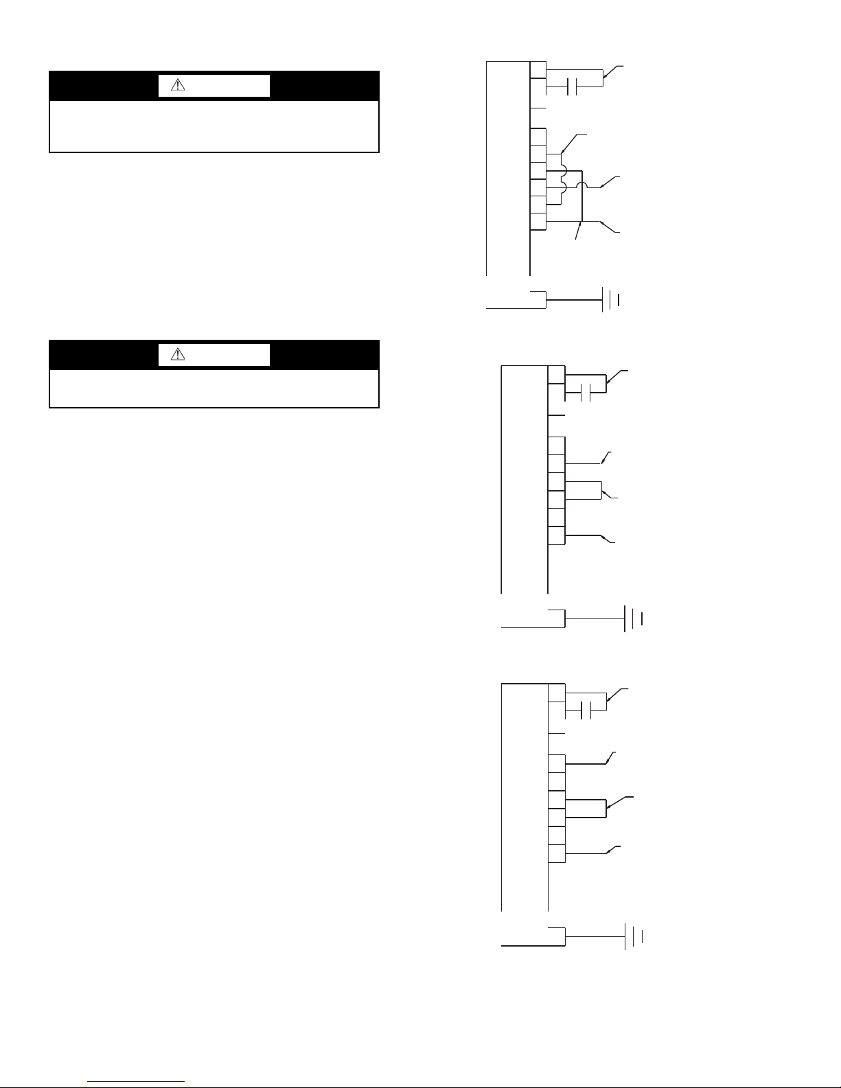
SERVICE
1 2 3 4 5 6
MOTOR
MOTOR
1 2 3 4 5 6
GREEN
BLACK #12
BLACK #12
TO
SCR CONTROLLER
BROWN TO
CAPACITOR
WHITE #12 TO
TERMINAL BLOCK/
DISCONNECT SWITCH
MOTOR
1 2 3 4 5 6
WARNING
LOCK OPEN AND TAG heater electrical disconnect
before working on this equipment. Otherwise, one leg of
the 3-leg heater remains energized.
BROWN TO
CAPACITOR
BLACK #12
Controls
No periodic preventive maintenance is necessary.
Fan Motor and Wheel
The fan motor and wheel are accessible from the bottom of
the unit. Remove the bottom panel to check the wiring or remove
the fan wheel or motor.
The PSC motors are equipped with long life sleeve bearings
with non-detergent SAE 20 oil biannually.
NOTE: The ECM motor has permanently lubricated ball bearings that require NO maintenance.
WARNING
Disconnect power to unit before touching fan motor wiring, or electrical shock or personal injury could result.
TO CHECK WIRING (REFER TO FIG. 18-20)
The PSC motor is connected by quick-connect terminals to
the capacitor (brown wire), the housing wire (green ground
wire), and the control box (black wire and white wire). Verify
that the fan motor wiring is correct as shown in these figures.
TROUBLESHOOTING
To remove the fan motor and wheel:
1. Disconnect motor wiring.
2. The fan motor and wheel assembly is attached to the discharge panel with 4 hex nuts.
3. Remove the motor by removing the 3 screws that attach the
torsion flex mounts to the inlet ring.
4. Remove wheel by unscrewing the hub set screws that are
accessed through the open end of the wheel.
Fan Motor Wiring
Refer to the fan motor wiring details shown on the wiring
diagram attached to the unit. Failure to reconnect the fan
properly can cause damage to the motor and/or serious personal injury.
Fan Motor Maintenance
Unit motors are equipped with permanently lubricated bearings. Inspect fan and motor assembly for accumulation of dust
and dirt as required by operating environment. Clean as necessary. See Fig. 18-20 for motor wiring.
WHITE #12 TO
TERMINAL BLOCK/
DISCONNECT SWITCH
CRIMPTIE WIRE 1
AND WIRE 4
Green
BLACK #12
SCR CONTROLLER
TO
Fig. 18 — PSC Motor Wiring Terminal Block —
115 V, Single Phase
Fig. 19 — PSC Motor Wiring Terminal Block —
208/240 V, Single Phase
BROWN TO
CAPACITOR
WHITE #12 TO
TERMINAL BLOCK/
DISCONNECT SWITCH
BLACK #12
BLACK #12
SCR CONTROLLER
TO
GREEN
Fig. 20 — PSC Motor Wiring Terminal Block —
277 V, Single Phase
22
Page 23

If fan motor does not run:
1. Make sure that there is free rotation of blower wheel.
2. Remove fan packing.
3. Verify that there is no freight or installation damage.
4. Check for proper unit power.
5. Disconnects should be on, and check optional fusing.
6. Check for proper control signal, pie switch setting, proper
air control 24 vac at fan contactor, and that the coil is energized.
If fan motor runs, excessive noise:
1. Make sure the blower, and all components have no clearance problems and are securely attached.
2. Verify the integrity of ductwork, make sure there are no
leaks or loose connections rattling diffusers or balancing
dampers.
3. Confirm that the maximum CFM not too high, or discharge
static pressure is too low.
If fan motor runs, insufficient airflow:
1. Check for ductwork restrictions, dirty air filters, and
clogged water coils.
2. Re-adjust fan speed control.
3. Discharge static pressure too high.
If repair or replacement is required:
1. Motor and fan should be removed as an assembly. Disconnect all power before servicing.
2. Remove the four hex nuts from the mounting lugs holding
the fan assembly to the discharge panel, and lower the assembly.
NOTE: Do not allow assembly to hang from wiring.
3. Loosen the setscrew if removing motor from blower.
4. Hold the blower wheel to the motor shaft. Remove the
three screws holding motor to the fan housing, and slide
motor and fan housing apart. Reverse the procedure for assembly.
NOTE: Overtightening motor mounting screws may crush isolation bushings, and cause excessive fan noise and wear.
23
Page 24

© Carrier Corporation 2018
Catalog No. 04-53450003-01 Printed in U.S.A. Form 45-5SI Pg 24 8-18 Replaces: 45-3SI
Manufacturer reserves the right to discontinue, or change at any time, specifications or designs without notice and without incurring obligations.
 Loading...