

Page 1
42TW/TD
Chilled Water
Fan Coil unit
with Remote Control
(50/60 Hz)
Insta
llation,
Se
ervice I
Start-
Instruct
Installation and servicing air-conditioning
equipment can be hazardous due to system
pressure and electrical components. Only trained
and qualified service personnel should install,
repair, or service air conditioning equipment.
Untrained personnel can perform basic
maintenance functions of cleaning coils and filters
and replacing filters.
All other operations should be performed by trained
service personnel When working on airconditioning equipment, observe precautions in the
literature, tags and labels attached to the unit, and
other safety precautions that may apply.
Follow all safety codes. Wear safety glasses and
work gloves. Use quenching cloth for un-brazing
operations. Have fire extinguishers available for all
brazing operations.
Up
and
tions
SAFETY CONSIDERATIONS
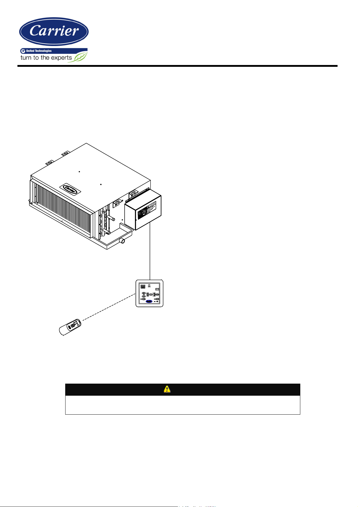
REMOTE CONTROL
Fig. 1 - 42TW Unit
ELECTRIC SHOCK HAZARD To avoid the possibility of electrical shock, open and tag all
service switches before installing this equipment.
CONTROL BOARD
WARNING
CONTENTS
Safety Consideration
Introduction
Receiving
Inspection
Protection
Preliminary Check
Physical Data
Sound Data
Fan Performance Data
Base Unit Dimensions
Prepare Jobsite
Identify and Prepare Units
Unit Configuration
Rigging and Unpacking
Installation
Page Page
1
Placing unit in position
2
Making Piping Connections
2
Electrical Heater Option
2
Test and Insulate
2
Make Electrical Connections
2
Make Duct Connections
2
Make Final Preparation
4
Control Board & Remote control
5
Typical wiring digram
6
Start-up
7
Service
7
Start-up Checklist
7
7
7
7
7
8
8
8
8
8
9,10
11,12
13
13
14
-1-
Page 2
- 2 -
INTRODUCTION
Size
03 05 06
07
09
11
12 16
CFM*
348
592
692
780
883
1181
1385
1572
Cooling Capacity (kw)*
3.4 6.1 7.5
8.9
9.9
11.5
14.5
16.9
Colling Capacity
(kbtuh)
11.7
20.7
25.6
30.4
33.8
39.2
49.5
57.7
SHR
0.75
0.74
0.72
0.71
0.71
0.75
0.73
0.73
Power Supply
208-230, 1 ph, 60 Hz / 220-240, 1 ph, 50 Hz / 110-127, 1 ph, 60 Hz
Motor HP(
Nominal)
1/15 1/10
1/15
1/10
Input W atts ( Med Speed, 25 Pa ESP)
56 64 70 80 80 130
146
160
Number of
Motors
1, 3
Speed
2, 3 Speed
Coil
Material
Smooth copper tubes/ Aluminum fins with double wavey fin
Coil Face Area,
m^2
0.11
0.15
0.21
0.26
0.31
0.31
0.44
0.52
Coil
Connection
Type
Sweat
Type
Coil
Connection Size
5/8
Inch
7/8
Inch
Number of
Rows
3
Fin Denisty/ Inch
14
Drain
Diameter
5/8
Inch
Blower type
Direct drive forward curved centerifugal fan
Blower
Number
1
2 4
Blower Diameter / Width, mm
156/220
156/170
156/220
156/170
156/220
Filter
Type
Washable Aluminum Filter
Width, mm
640
800
1010
1220
1430
1430
1430
1640
Depth, mm
590
Height, mm
275
375
Net Weight, kg
18 23 28 32 39 43 49 56
This document contains general installation
instructions for the 42TW unit Fan Coils. Refer
to the unit-wiring diagram installed on the
blower housing or specific manufacturer
literature for any other type of factory-mounted
controls.
See drawings for unit configurations,
dimensions, clearances, and pipe
connections. Refer to unit wiring label for all
electrical connections; follow NEC (National
Electrical Code) and local codes.
RECEIVING
42TW fan coil units are shipped individually
packed in carton boxes. When cartons are
individually off loaded from the truck, do not
roll, nor throw, or drop the carton to avoid
damage to the contents. Store boxes upright
as the symbols on the boxes indicated. Do
not stack units more than 6 units high for size
11-16 and 8 units high for other sizes.
INSPECTION
Check the shipment against shipping list and
remove unit from the carton and take off
protective covering. If the unit has been
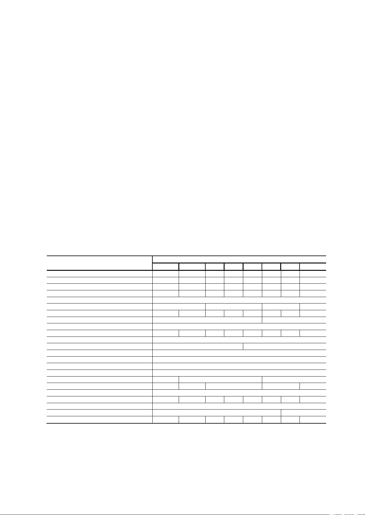
Table.1 -
Physical
Model 42TW3
Model
42T
Data - 42TW3, 42TD3 – 2 Pipe
D3
damaged, file claim with transportation
company and notify Carrier immediately.
PROTECTION
Protection unit from damage caused by job
site debris. Do not allow dust, debris and
water to get into the unit. These will damage
unit’s component and unit’s performance will
be affected.
PRELIMINARY
Following is a checklist which should be
checked before the installation is started. The
installer should be familiar with each of the
following requirements before the actual
installation.
- Space requirement and clearance, See
Fig.3.
- Ceiling or mounting strength.
- Piping connections.
- Condensate drain connection.
- Power supply and wiring.
- Air duct connections.
System
CHECK
* At 26.7/19 c approch 6.7c water inlet/12.7c water outlet, High speed @ 0 Static
Page 3

- 3 -
Model 42TD 4
Size
03 04 05
06
08
10
11 14
CFM*
313
533
623
702
795
1065
1247
1416
Cooling Capacity (kw)*
3.8 6.2 7.7
9.0
9.9
12.7
15.7
17.6
Colling Capacity
(kbtuh)
13.0
21.0
26.3
30.8
33.7
43.3
53.6
60.1
SHR
0.69
0.71
0.69
0.69
0.69
0.7
0.68
0.69
Power Supply
208-230, 1 ph, 60 Hz / 220-240, 1 ph, 50 Hz / 110-127, 1 ph, 60 Hz
Motor HP
(Nominal)
1/15 1/10
1/15
1/10
Input W atts ( Med Speed, 25 Pa ESP)
52 60 65 75 75 121
136
150
Number of
Motors
1, 3
Speed
2, 3 Speed
Coil
Material
Smooth copper tubes/ Aluminum fins with double wavey fin
Coil Face Area
0.11
0.15
0.21
0.26
0.31
0.31
0.44
0.52
Coil
Connection
Type
Sweat
Type
Coil
Connection Size
5/8
Inch
7/8
Inch
Number of
Rows
4
Fin Denisty/ Inch
14
Drain
Diameter
5/8
Inch
Blower type Direct drive forward curved centerifugal fan
Blower
Number
1
2 4
Blower Diameter /
Width
156/220
156/170
156/220
156/170
156/220
Filter
Type
Washable Aluminum Filter
Width 640
800
1010
1220
1430
1430
1430
1640
Depth
590
Height
275
375
19 24 29 33 41 45 51 58
Model 42TW4
Size
03 04 05
06
08
10
11 14
CFM*
313
533
623
702
795
1065
1247
1416
Cooling Capacity (kw)*
3.4 5.3 6.9
8.0
8.9
11.2
14.1
15.9
Colling Capacity
(kbtuh)
11.6
18.1
23.5
27.3
30.4
38.2
48.1
54.3
Heating Capacity (kw)**
2.9 5.5 6.8
7.9
9.4
12.2
13.9
17.5
Heating Capacity
(kbtuh)
9.9 18.8
23.2
27.0
32.1
41.6
47.4
59.7
Power Supply
208-230, 1 ph, 60 Hz / 220-240, 1 ph, 50 Hz / 110-127, 1 ph, 60 Hz
Motor HP
(Nominal)
1/15 1/10
1/15
1/10
52 60 65 75 75
121
136
150
Number of
Motors
1, 3
Speed
2, 3 Speed
Coil
Material
Smooth copper tubes/ Aluminum fins with double wavey fin
Coil Face Area
0.11
0.15
0.21
0.26
0.31
0.31
0.44
0.52
Coil
Connection
Type
Sweat
Type
Coil
Connection
Size Cool & Heat
3/4 Inch & 5/8
Inch
Number of
Rows
4
Fin Denisty/ Inch
14
Drain
Diameter
5/8
Inch
Blower type
Direct drive forward curved centerifugal fan
Blower
Number
1
2 4
Blower Diameter /
Width
156/220
156/170
156/220
156/170
156/220
Filter
Type
Washable Aluminum Filter
Unit
Dimensions
640
800
1010
1220
1430
1430
1430
1640
590
275
375
Net
Weight
19 24 29 33 41 45 51 58
Table.2 -
Physical
Data - 42TW4,42TD4 – 2 Pipe
System
Model 42TW4
Net
Weight
* At 26.7/19 c approch 6.7c water inlet/12.7c water outlet, High speed @ 0 Static
Table.3 -
Physical
Data - 42TW4, 42TD4 – 4 Pipe
System
Model 42TD4
Width,
Depth,
mm
mm
Height, mm
* At 26.7/19 c approch 6.7c water inlet/12.7c water outlet, High speed @ 0 Static
** At 20 /14 c approch 70c water inlet/61.6c water outlet, High speed @ 0 Static
Page 4
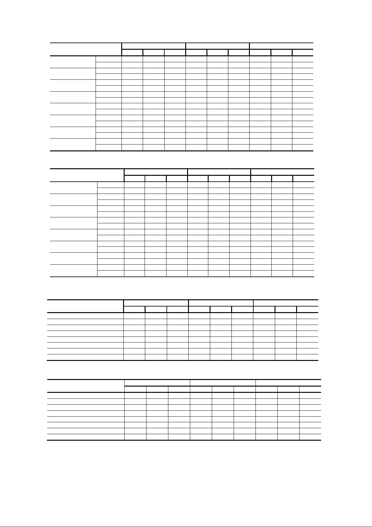
Table.4 a - POWER CONSUMPTION 42TW,42TD 3ROW
42TW,42TD ± 3Row
-03
-05
-06
-07
-09
-11
-12
-16
Amps
Watts
Amps
Watts
Amps
Watts
Amps
Watts
Amps
Watts
Amps
Watts
Amps
Watts
Amps
Watts
@ 0 Pa ESP @ 25 Pa ESP @ 50 Pa ESP
Hi Med Low Hi Med Low Hi Med Low
0.40 0.35 0.30 0.34 0.28 0.24 0.30 0.25 0.20
80 70 60 68 56 48 60 50 40
0.45 0.40 0.35 0.37 0.32 0.27 0.33 0.28 0.22
90 80 70 74 64 54 66 56 44
0.55 0.45 0.35 0.45 0.35 0.27 0.40 0.30 0.22
110 90 70 90 70 54 80 60 44
0.60 0.50 0.40 0.50 0.40 0.30 0.45 0.35 0.25
120 100 80 100 80 60 90 70 50
0.60 0.50 0.40 0.50 0.40 0.30 0.45 0.35 0.25
120 100 80 100 80 60 90 70 50
0.90 0.80 0.70 0.75 0.65 0.55 0.65 0.55 0.45
180 160 140 150 130 110 130 110 90
1.10 0.90 0.70 0.90 0.73 0.55 0.80 0.62 0.45
220 180 140 180 146 110 160 124 90
1.20 1.00 0.80 1.00 0.80 0.62 0.80 0.70 0.50
240 200 160 200 160 124 160 140 100
Table.4 b
42TW,42TD ± 4Row
-03
-04
-05
-06
-08
-10
-11
-14
Note: For 220V, 1 Phase Motor.
Amps
Watts
Amps
Watts
Amps
Watts
Amps
Watts
Amps
Watts
Amps
Watts
Amps
Watts
Amps
Watts
@ 0 Pa ESP @ 25 Pa ESP @ 50 Pa ESP
Hi Med Low Hi Med Low Hi Med Low
0.37 0.33 0.28 0.33 0.27 0.23 0.29 0.24 0.20
73 64 55 64 52 45 57 48 38
0.42 0.37 0.33 0.36 0.31 0.26 0.32 0.27 0.22
82 73 64 69 60 50 63 53 42
0.51 0.42 0.33 0.43 0.34 0.26 0.39 0.29 0.22
100 82 64 84 65 50 76 57 42
0.56 0.47 0.37 0.48 0.38 0.29 0.44 0.34 0.24
109 91 73 93 75 56 86 67 48
0.56 0.47 0.37 0.48 0.38 0.29 0.44 0.34 0.24
109 91 73 93 75 56 86 67 48
0.84 0.75 0.65 0.72 0.62 0.53 0.64 0.54 0.44
164 145 127 140 121 103 124 105 86
1.03 0.84 0.65 0.86 0.70 0.53 0.78 0.61 0.44
200 164 127 168 136 103 152 118 86
1.12 0.93 0.75 0.96 0.77 0.60 0.78 0.68 0.49
218 182 145 187 150 116 152 133 95
Table.5 a -SOUND PRESSURE
42TW,42TD ± 3Row
42TW3-03
42TW3-05
42TW3-06
42TW3-07
42TW3-09
42TW3-11
42TW3-12
42TW3-16
@ 0 Pa ESP @ 25 Pa ESP @ 50 Pa ESP
Hi Med Low Hi Med Low Hi Med Low
47.5 45.5 43.5 46.5 44.0 42.5 45.5 42.5 41.0
48.5 46.5 44.5 47.5 45.0 43.5 46.5 43.5 42.0
50.0 48.0 46.0 49.0 46.5 45.0 48.0 45.0 43.5
50.5 48.5 46.5 49.5 47.0 45.5 48.5 45.5 44.0
50.0 48.0 46.0 49.5 47.0 45.5 48.5 45.5 43.5
51.0 49.0 47.0 50.0 47.5 46.0 49.0 46.0 44.0
51.0 49.0 47.0 50.0 47.5 46.0 49.0 46.0 44.5
51.5 49.5 47.5 50.5 48.0 46.5 49.5 46.5 45.0
Table.5 b
42TW ± 4Row
42TW4-03
42TW4-04
42TW4-05
42TW4-06
42TW4-08
42TW4-10
42TW4-11
42TW4-14
Note: Assumes "standard room ", 3 meters from exit, no ducts, ducts will further reduce sound
@ 0 Pa ESP @ 25 Pa ESP @ 50 Pa ESP
Hi Med Low Hi Med Low Hi Med Low
46.5 44.5 42.5 46.0 43.5 42.0 45.0 42.0 40.5
47.5 45.5 43.5 47.0 44.5 43.0 46.0 43.0 41.5
49.0 47.0 45.0 48.5 46.0 44.5 47.5 44.5 43.0
49.5 47.5 45.5 49.0 46.5 45.0 48.0 45.0 43.5
49.0 47.0 45.0 49.0 46.5 45.0 48.0 45.0 43.0
50.0 48.0 46.0 49.5 47.0 45.5 48.5 45.5 43.5
50.0 48.0 46.0 49.5 47.0 45.5 48.5 45.5 44.0
50.5 48.5 46.5 50.0 47.5 46.0 49.0 46.0 44.5
-4-
Page 5
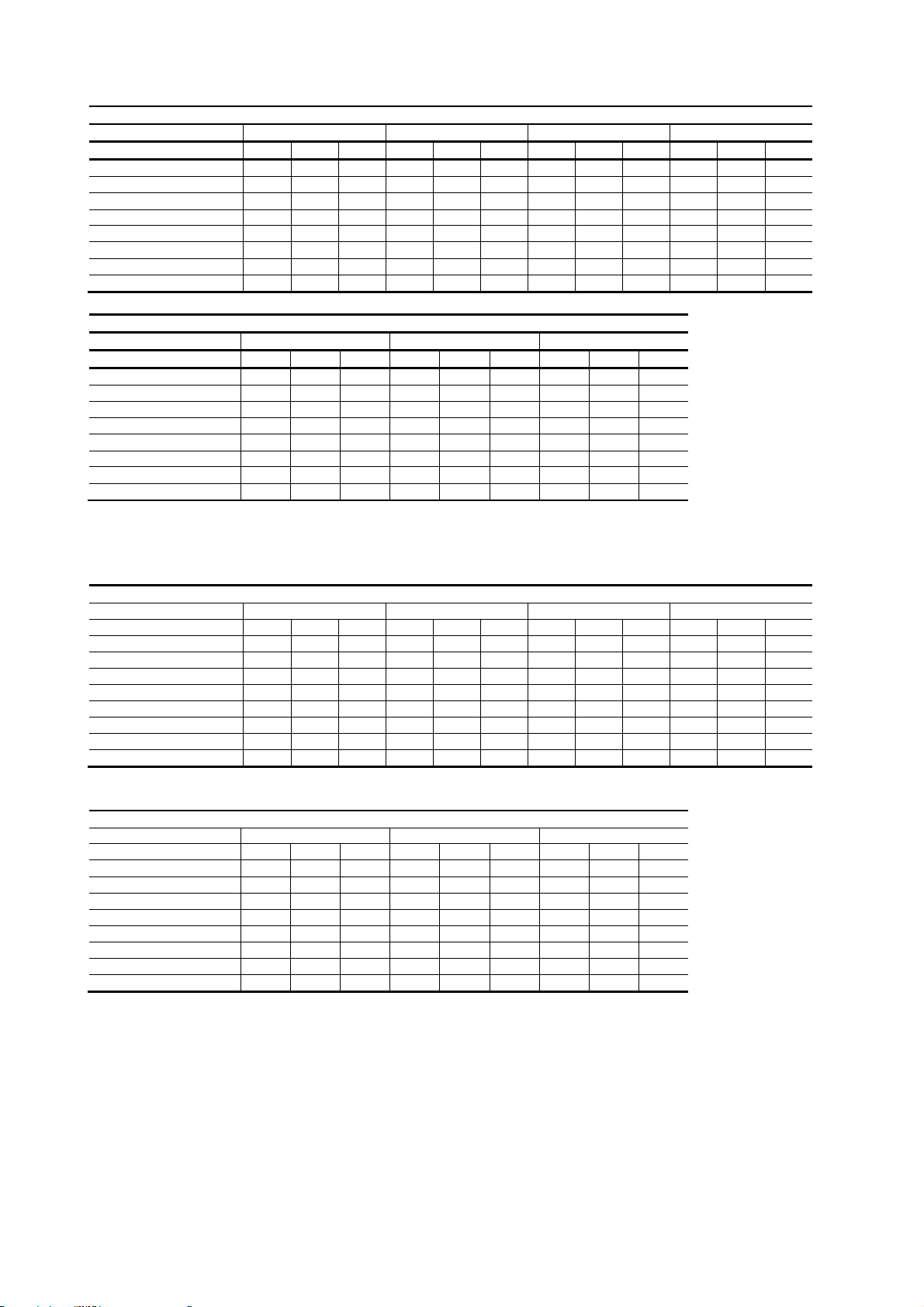
Table.6 a - Fan Performance ± 42TW-3-SI
L
423
629
845
938
1011
1257
1690
1876
L
383
572
769
854
919
1144
1538
1707
42TW3 Air Flow (m3/hr)
Ex. Static Pres. Pa 0 12.5 25 37.5
Unit Size H M L H M
03
05
06
07
09
11
12
16
592 515 466 568 481
1005 846 694 940 761
1176 995 931 1132 943
1325 1174 1031 1284 1090
1500 1285 1120 1420 1178
2007 1690 1385 1879 1521
2353 1991 1862 2265 1886
2671 2349 2062 2569 2180
42TW3 Air Flow (m3/hr)
Ex. Static Pres. Pa 50 62.5 75
Unit Size H M L H M L H M L
03
05
06
07
09
11
12
16
H ± At High Fan Speed.
M ± At Medium Fan Speed.
L ± At Low Fan Speed.
460 358 250 380 270 ± 305 ±±
718 541 389 625 439 ± 524 ±±
919 715 499 737 541 ± 559 ±±
1031 788 634 890 651 ± 769 ±±
1120 865 650 1000 740 ± 862 ±±
1437 1082 777 1251 879 ± 1048 ±±
1839 1430 997 1437 1055 ± 1091 ±±
2062 1575 1268 1770 1295 ± 1530 ±±
HML HML
544 446 380 502 402 315
875 676 564 794 600 473
1088 891 759 1024 791 634
1243 1006 845 1158 896 752
1340 1071 902 1230 968 776
1751 1352 1129 1589 1200 946
2177 1781 1518 2048 1582 1268
2467 2011 1690 2315 1791 1504
Table.6 b - Fan Performance ± 42TW - 4 - SI
42TW4 Air Flow (m3/hr)
Ex. Static Pres. Pa 0 12.5 25 37.5
Unit Size H M L H M
03
05
06
07
09
10
11
14
532 463 419 517 437
905 764 625 855 693
1059 896 840 1030 858
1192 1058 931 1168 992
1350 1156 1007 1291 1072
1809 1524 1249 1710 1384
2119 1793 1679 2061 1716
2406 2118 1859 2338 1984
42TW4 Air Flow (m3/hr)
Ex. Static Pres. Pa 50 62.5 75
Unit Size H M L H M L H M L
03
05
06
07
09
10
11
14
H ± At High Fan Speed.
M ± At Medium Fan Speed.
L ± At Low Fan Speed.
433 336 235 363 279 ± 296 ±±
675 509 366 594 417 ± 503 ±±
864 672 469 700 514 ± 537 ±±
969 741 596 846 618 ± 738 ±±
1063 813 602 950 715 ± 825 ±±
1351 1017 730 1188 835 ± 1006 ±±
1729 1344 937 1365 1002 ± 1047 ±±
1938 1481 1192 1682 1230 ± 1469 ±±
HML HML
502 411 350 467 373 292
805 622 519 738 558 440
1001 820 698 952 736 590
1144 926 777 1077 833 699
1232 987 831 1148 900 717
1611 1244 1039 1478 1116 880
2003 1639 1397 1905 1471 1179
2270 1850 1555 2153 1666 1399
-5-
Page 6

Page 7

PREPARE JOSITE FOR UNIT INSTALLATION
To save time and to reduce the possibility of
costly errors, set up a complete sample
installation in a typical room at jobsite. Check all
critical dimensions such as pipe, wire, and duct
connection requirements. Refer to job drawings
and product dimension drawings as required.
Instruct all trades in their part of the installation.
IDENTIFY AND PREPARE UNITS
Be sure power requirements match available
power source. Refer to unit nameplate and
wiring diagram.
1. Check all tags on unit to determine if shipping
screws are to be removed. Remove screws as
directed.
2. Rotate the fan wheel by hand to ensure that
the fan is unrestricted and can rotate freely.
Check for shipping damage and fan
obstructions.
UNIT CONFIGURATION
The piping connections, drain pan outlet and control
box are located on the right side of the unit facing the
airflow direction as factory standard as shown in the
unit picture. Left hand side connection is factory
option. However, the connections side can be
relocated at site.
RIGGING AND UNPACKING
Unit should not be removed from carton until reaching
final location to avoid damage. Inspect unit for
shipping damage and file claim with transportation
company if necessary, check nameplate voltage
against available power supply. For special installation,
consult local building and electrical codes.
INSTALLATION
PLACING UNIT IN POSITION
1. Select the unit location. Allow adequate space
for free air circulation, service clearances, piping
and electrical connections, and any necessary
ductwork, see fig.2. For specific unit dimensions,
refer to the submittal drawings. Allow clearances
according to the local and national electrical
codes.
2. Be sure either the ceiling is able to support the
weight of the unit. See Table 1-3 for nominal unit
weight.
3. Move unit into position. Ensure unit is level or
pitched towards drain to ensure proper drainage
and operation.
4. Mounting units to the ceiling - When unit is
lifted, access to the. mounting holes is on the top
panel of the unit. Hanger rods, fasteners, and
other required hardware must be field-supplied.
MAKING PIPING CONNECTONS
Qualified personnel in accordance with local and
national codes must perform all piping
connections. Refer to Fig.2 for piping
connections.
NOTE: It is important to have a common
understanding of which side of the unit is the right
hand side and which is the left hand side. When
facing the supply air outlet from the front of the
unit (air blowing in your face), your right hand will
be on the right side of the unit and your left hand
will be on the left side of the unit. See Fig. 5.
Fig.3 ± Minimum clearance required. Fig4- Changing the coil connection side
Fig.5 ± Unit end reference
-7-
Page 8

Table.7 - ELECTRIC HEATER OPTION
(2 Pipe System)
42TW 3 Ro
ws Models 42TW 4 Rows Models Heater option, watts
42TW3-03
42TW3-05
42TW3-06
42TW3-07
42TW3-09
42TW3-11
42TW3-12
42TW3-16
42TW4-03 2000
42TW4-04 2000
42TW4-05 2000
42TW4-06 2500
42TW4-08 2500
42TW4-10 4000
42TW4-11 4000
42TW4-14 4000
TEST AND INSULATE
When all joints are complete, perform hydrostatic
test for leaks. Vent all coils at this time. Check
interior unit piping for signs of leakage from
shipping damage or mishandling. If leaks are
found, notify a Carrier representative before
initiating any repairs. Release trapped air from
system (refer to Make Final Preparations section).
MAKE ELECTRICAL CONNECTIONS
Refer to unit nameplate for required supply
voltage, fan and heater amperage and required
circuit ampacity. Refer to unit wire diagram for unit
and field wiring; see fig.6 . Make sure all electrical
connections are in accordance with unit wiring
diagram and all applicable codes. The fan
motor(s) should never be controlled by any wiring
or device other than the factory-supplied control
board and remote control.
All field wiring must be in accordance with
governing codes and ordinances. Any modification
of unit wiring without factory authorization will
invalidate all factory warranties and nullify any
agency listings.
- Select proper wall location to fix display pad
- Connect communication cable end to its
location in the PCB as shown in the wiring
diagram.
IMPORTANT
Wiring diagrams shown depict typical control
functions. Refer to unit wiring label for specific
functions.
minimize duct-to-unit alignment problems and
noise transmission where specified.
Set unit markings for minimum clearance to
combustible materials and first 3 ft of
ductwork. Install ductwork, accessory grilles
and plenums so that they do not restrict
access to filter.
Cut openings for supply-air and return-air
grilles. Be careful not to cut wires, piping or
structural supports.
CAUTION
Prevent dust and debris from settling in
unit. If wall finish or color is to be spray
applied, cover all openings to prevent
spray from entering unit. Unit efficiency
will be reduced.
MAKE FINAL PREPARATIONS
1. Turn off power to the unit (open unit
electrical disconnect).
3. Clean dirt, dust, and other construction
debris from unit interior. Be sure to check fan
wheel and housing.
4. Rotate fan wheel by hand to be sure it is
free and does not rub housing. Check that
wing nuts securing fan assembly to fan deck
are tight.
5. Ensure all panels and filters are installed
before checking fan operation. Turn on power
to the unit.
MAKE DUCT CONNECTIONS
Install all ductwork to and from unit in
accordance with all applicable codes. Duct
construction must allow unit to operate within
duct external static pressure limits as shown
on job submittals. Units designed to operate
with ductwork may be damaged if operated
without intended ductwork attached.
Units provided with outside air should have
some method of low-temperature protection
to prevent freeze-up. Insulate ductwork as
required. Use flexible connections to
IMPORTANT
Do not start-up or operate unit without
filter. Be sure filter and unit interior are
clean.
8. Be sure drain line is properly and securely
positioned and that the line is clear. Pour
water into drain to check operation.
- 8 -
Page 9

Controller For Ducted Fan Coil Units
DIP Switch
On
Off
SW1
Cool
Cool-Heat
SW2
Water System
DX System
Room sensor fault
E1
Indoor coil sensor fault
E2
Comp fault
E4
“COOL” Led
Lights on when selecting COOL mode.
“DRY” Led
Lights on when selecting DRY mode.
“HEAT” Led
Lights on when selecting Heat mode.
“FAN” Led
Lights on when selecting FAN mode.
Wired Room
Notes: The wired room controller is mounted on the wall and can control all system functions without wireless remote control.
Wired Room Controller
Wireless Room Controller
- 9 -
Features: The controller is used to control air cooled ducted split unit, supports the following functions:
- Modes: Cool, Dry, Fan, Heat
- Indoor fan speed: Auto, High, Medium, Low
- Sleep mode
- Compressor protections:
Comp 3 minutes restart protection
Indoor coil anti-freeze
Room sensor and indoor coil sensor failure monitoring
- Non volatile memory – keep system settings
- Programmable On/Off timer
- Random restart to minimize voltage dip during compressor first cut in cycle upon power up.
Hardware Setting: A 2 way DIP switch is used to configure:
Error Code: If multiple faults happen at the same time, the corresponding error code will be shown one after
another
Split System Description
1) On/Off Key: If you press this key, the system will begin operation, Press the key again, and operation stops.
(You can hear a receiving beep). If you press this key immediately after turning off the system, the compressor will
not operate for 3 minutes to prevent overloading.
2) Operation Mode Selection Key: Toggles the operation mode: Cool, Dry, Heat, or Fan only
3) Fan Speed Selection Key: Toggles the fan speed: Auto, High, Medium, or Low, Note: Fan key is invalid in Dry
mode.
4) Temperature Up Key:
press.
5) Temperature Down Key: By pressing temperature down key, the setting temperature decreases by 1ºC with
each press. If you set the desired room temperature, then system will maintain the room temperature as set. Upon
setting the desired room temperature the system will maintain the room temperature
Controller (Standard)
Fault Error code
By pressing Temperature up Key, the setting temperature increases by 1ºC with each
Page 10

Cool Mode
FAN
Menu
Parameter
Set Range
Default value
Remarks
1: Disable room temp display
2: Enable room temp display
1: Comp OFF, Fan ON
2: Comp OFF, Fan OFF
1: Heater OFF, Fan ON
2: Heater OFF, Fan OFF
- 10 -
: If the room temperature is higher than the setting, the compressor will automatically turn on provide a
cooling effect. On the hand, if the room temperature is lower than the setting, the compressor will automatically turn
off to stop cooling operation. If indoor fan is programed to be turned off with comp signal, it will turn off once comp
is cut off
Heat Mode: If the room temperature is lower than the setting, the Electric heater will automatically turn on to
provide a heating effect. If the room temperature is higher than the setting, the heater will automatically turn off to
stop heating operation. If indoor fan is programed to be turned off with heater signal, it will turn off once heater is
cut off but subject to 30 sec dispersing remaining heat timing.
Dry Mode: The fan speed runs automatically at low speed and compressor stopping and running is controlled by
the difference between room and setting temperatures and by continuous running time. If indoor fan is programed
to be turned off with comp signal, it will turn off once comp is cut off
- In Dry mode, the humidity is reduced in the space to be air-conditioned.
Fan Mode: There will be no cooling or heating effects; only the fans of indoor unit will run for ventilation at the
selected speed (High, Med, and Low).
- In COOL or HEAT mode and if AUTO fan speed is selected; Fan speed is automatically selected by controller
according to the difference between setting temperature and room temperature, fan will be continuously
running at low speed after setting temperature is achieved.
Notes:
a) Temperature setting range is 16ºC to 30ºC or 60ºF to 85ºF.
b) Hold down at the same time for about 5 seconds, Temp down and fan keys will toggle the temperature
setting from degree C to degree F and vice versa.
c) Press any temperature key will flash the current setting temperature for 4 seconds, Should there be no
further key press, it will revert to room temperature display. Temperature display range is 0 C to 50 C or 32 F
to 99 F.
d) Temp keys are invalid in Fan mode.
6) Sleep Key: Press this key to set the SLEEP timer and then the sleep led will light on, to cancel the sleep timer
press this key again.
- Sleep function for healthy sleep to control automatically the room temperature and stop automatically the
operation of the air conditioner after certain set off time.
- Sleep mode is valid in cool or heat mode and invalid in Fan mode.
7) Timer Key: Upon count down of the set hours, the system will switch from OFF to ON or vice-versa.
- OFF Timer Function to stop automatically, the air conditioner after certain set OFF time.
- ON Timer Function to start automatically, the air conditioner after certain set ON time.
* Timer setting is 1 Hour to 24 Hour. The timer led will light on when operating the Timer Function
First key press will flash the digital display and Timer Led for 3 seconds.
Notes:
a) The digital displays show the number of hours previously set, only the Timer Led flashes.
b) Subsequent 3 seconds will show the number of hours previously set; only the timer led flashes.
c) Should there be no further key press, it will revert to normal mode.
d) Should Timer key is not released timer setting will increase automatically every 0.5-second.
8) Sensor: Receives the remote controller’s signal
9) Display Screen:
Displays the set temperature and displays also the TIMER settings when adjusting it.
10) Key Lock Mode: To activate key lock mode, hold down for 3 seconds, temp. Down Key (5) and Mode Key (2).
In key lock mode, all keys are not valid except ON/OFF Key (1) to turn ON/OFF the system.
Notes:
a) Hold down Temp Down and Sleep button for one second to enter into coil temperature display mode.
Press Temp Up key to display indoor coil temperature, High Fan LED flashes. With the same sequence to
exit coil temperature display mode. Temperature display range is -9C to 78 ºC.
b) Hold down
to activate temperature display setting and auto fan LED flashes. Repeat the same sequence to cancel
this function. Press
temperature display and “2” means enable room temperature display.
Temperature display, Auto fan
1
LED flashing
Cool mode fan control function,
2
Auto & High fan LED flashing
Heat mode fan control function,
3
Auto & Medium fan LED flashing
and
buttons for only 1 second ( 5 sec to toggle between ºC and ºF temperature )
or button to change the setting from 1 to 2. “1” means disable room
1~2 1
1~2 1
1~2 1
Page 11

WIRING SCHEMATIC 42TW/TD COOL/HEAT
-11-
Page 12

WIRING SCHEMATIC 42TW/TD COOL/HEAT WITHOUT CONTROL
-12-
Page 13

START-UP
42TW unit is designed to operate in hot and
humid conditions without condensation
problem because of the rubber insulated
drain pan. Refer to the startup checklist in
page 11 for startup procedure.
SERVICE
TO CLEAN COIL
1. Be sure electrical service switch is open,
locked, and tagged while working on unit.
2. Remove supply-air grille access panel and
brush between coil fins with stiff wire brush.
Follow-up by cleaning with vacuum cleaner. If
coil is cleaned with air hose and nozzle, take
care not to drive dirt and dust into other
components.
CHECK DRAIN
Lock open and tag unit electrical service
switch.
Check drain pan, drain line and trap at start
of each cooling season. A standard type pipe
cleaner for 5/8-in. ID pipe can be used to
ensure that pipe is clear of obstruction so that
condensate is carried away.
CLEAN FAN WHEEL
Lock open and tag unit electrical service
switch.
For access to fan assembly, remove front or
bottom panel.
Fan assembly may be removed from its
tracks if unit has a long conduit lead. Use a
stiff brush or vacuum to remove dirt and
debris from scroll.Wipe all fan surfaces with a
damp cloth.
CLEAN ELECTRIC HEATER
Lock open and tag unit electrical service
switch.
1. Remove dust, dirt, or foreign material
before start-up. Do not block normal airflow to
and from units; blockage may damage
electric heaters.
2. Clean heater elements with soft brush or
vacuum cleaner as necessary.
CLEAN OR REPLACE AIR FILTERS
Lock open and tag unit electrical service
switch.
At the start of each cooling season and after
each month of operation (more or less
depending on operating conditions) replace
throwaway filter or clean permanent filter.
THROWAWAY FILTER ² Replace filter with
a good quality filter. Do not attempt to clean
and reuse disposable filters.
PERMANENT FILTER
1. Tap on solid surface to dislodge heavy
particles.
2. Wash in hot water.
3. Set filter on end so that water drains out
through slots in frame. Allow filter to dry
thoroughly.
See Fig.7 for filter access.
Fig.7 ± Filter Access.
-13-
Page 14

START-UP CHECKLIST FOR 42TW SERIES FAN COIL UNIT
I. Project Information
Job Name
_______________________________________________________________________
Address ________________________________________________________________________
City ______________________________________________State __________ Zip __________
Installing Contractor
_______________________________________________________________
Sales Office _____________________________________________________________________
Start-up Performed By
_____________________________________________________________
INSPECTION, INSTALLATION, & START-UP CHECKLIST
ITEM COMPLETE ITEM COMPLETE
Receiving & Inspection
1. Unit received undamaged
2. Unit received complete as ordered
3. Unit arrangement/hand correct
4. Unit structural support complete &
correct
Handling & Installation
5. Mounting grommets / isolators
used
6. Proper access provided for unit &
accessories
9. Proper electrical service provided
7. Proper overcurrent protection
provided
8. Proper service switch / disconnect
provided
9. Proper refrigerant line sizes to unit
10. All service to unit in code
compliance
11. All shipping screws & braces
removed
12. Unit protected from direct &
foreign matter
Cooling / Heating Connections
13. Connect field piping to unit
14. Pressure test all piping for leaks
15. Install drain line & traps as
required
16. Insulate all piping as required
Ductwork Connections
17. Install ductwork, Fittings, &
Grilles as required
18. Flexible duct connections at unit
19. Proper supply & return grille type
& size used
20. Insulate all ductwork as required
Electrical Connections
21. Refer to unit wiring diagram
22. Connection incoming power
service(s)
23,QVWDOOFRQQHFWLRQ³IXUQLVKRQO\´
parts
24. All field wiring in code compliance
Unit Startup
25. General visual unit & system
inspection
26. Check for proper fan belt tension
27. Check for proper fan rotation
28. Record electrical supply voltage
29. Record ambient temperatures
30. Check all wiring for secure
connections
31. Close all unit isolation valves
32. Flush water systems
33. Fill systems with water /
refrigerant
34. Vent water systems as required
35. All ductwork & grilles in place
36. All unit panels & filters in place
37. Start fans, pumps, chillers, etc.
38. Check for overload condition of all
units
39. Check all ductwork & units for air
leaks
40. Balance air systems as required
41. Record all final settings for future
use
42. Check piping & ductwork for
vibration
43. Verify proper cooling operation
44. Verify proper heating operation
45. Reinstall all covers & access
panels
-14 -
Page 15

NOTES
Page 16

Manufacturer reserves the right to discontinue, or change at any time, specifications or designs without notice and without incurring obligations
2015
42TW/TD - 05 - IOM
 Loading...