


42KC, 45UC, 45XC, 35BF
Access Floor Terminal Units
Installation, Operation and
Configuration Instructions
AXIS™
CONTENTS
Page
SAFETY CONSIDERATIONS...................... 1
GENERAL ...................................... 2-5
System Overview ................................ 2
System Architecture ............................. 3
PRE-INSTALLATION.............................. 6
Unpack and Inspect Units ........................ 6
Storage and Handling ............................ 6
Prepare Jobsite for Unit Installation.............. 6
45XC FAN-POWERED ZONE MIXING UNIT
INSTALLATION.............................. 6-27
45XC Hardware................................... 7
45XC Field-Supplied Hardware ................... 7
45XC Fan-Powered Zone Mixing Box
Installation ..................................... 9
45XC Sensor Installation ........................14
45XC Input and Output Connectors ............. 25
Connect to the CCN Communication Bus .......26
Connect Air Pressure Tubing.................... 26
45UC UNDERFLOOR SERIES FAN-POWERED
TERMINAL INSTALLATION ................. 27-35
45UC Hardware.................................. 27
45UC Field-Supplied Hardware .................. 27
45UC Underfloor Series Fan-Powered Unit
Installation ....................................29
45UC Sensor Installation ........................30
Connect to the CCN Communication Bus .......30
Modulating Baseboard Hydronic Heating........35
42KC PERIMETER FAN COIL UNIT
INSTALLATION............................. 36-45
42KC Hardware.................................. 36
42KC Field-Supplied Hardware .................. 37
42KC Perimeter Fan Coil Unit Installation ....... 37
Connect the Power Transformer................. 38
Fan Coil Controller Inputs and Outputs .........44
42KC Sensor Installation ........................44
35BF DIFFUSER INSTALLATION.............. 46-49
35BF-R Swirl Diffuser Installation ............... 46
35BF-CT,D,V Linear Diffuser Installation......... 46
OPERATION .................................. 50,51
Initial Start-Up Procedures ...................... 50
45XC Start-Up and Checkout Procedure......... 50
42KC Start-Up................................... 50
Page
CONFIGURATION ............................ 51-68
45XC Commissioning ........................... 51
45XC Set-Up and Configuration .................51
42KC Set-Up and Configuration .................57
42KC Fan Coil Airflow Adjustment .............. 57
Setting Fan Airflow with ECM ................... 57
Balancing Underfloor Fan Terminals ............ 57
Speed Controller ................................ 60
Set Points ....................................... 60
Testing and Start-Up ............................ 61
45XC Operation ................................. 62
42KC Fan Coil Sequence ........................ 66
45XC Application Considerations ............... 66
Maintenance ................................... 67
SAFETY CONSIDERATIONS
SAFETY NOTE
Air-handling equipment will provide safe and reliable
service when operated within design specifications. The
equipment should be operated and serviced only by
authorized personnel who have a thorough knowledge
of system operation, safety devices and emergency
procedures.
Good judgement should be used in applying any manufacturer’s instructions to avoid injury to personnel or
damage to equipment and property.
Disconnect all power to the unit before performing maintenance or service. Unit may automatically start if power is
not disconnected. Electrical shock and personal injury
could result.
If it is necessary to remove and dispose of mercury contactors in electric heat section, follow all local, state, and federal laws regarding disposal of equipment containing
hazardous materials.
Manufacturer reserves the right to discontinue, or change at any time, specifications or designs without notice and without incurring obligations.
Book 3 3
Ta b 6 a 7 a
Catalog No. 04-53450001-01 Printed in U.S.A. Form 45-4SI Pg 1 11-05 Replaces: 45-2SI

GENERAL
The 45XC fan-powered mixing box provides plenum pressure and temperature control to the underfloor plenum. The
45XC mixing box is also equipped with a modulating primary
air damper and a variable speed fan. Together, these features
allow the 45XC unit to maintain plenum pressure at the desired
pressure set point while adjusting the plenum temperature to
match the load requirements.
The 45UC series underfloor fan-powered terminal and the
42KC fan coil unit are used to provide increased cooling or
supplemental heating to perimeter zones. These units are available with factory-installed electric or hot water heating coils.
The controllers are factory-mounted. The 33ZCPLNCTL
zone controller is supplied on the 45XC fan-powered mixing
box. The 33ZCFANTRM underfloor controller is supplied on
the 45UC underfloor fan-powered terminal. The 42KC fan coil
units contain the 33ZCFANCOL perimeter fan coil controller.
All are designed to be an integral part of the Carrier Direct Digital Controls (DDC) system. The controllers can communicate
on the Carrier Comfort Network® (CCN) system while completely integrating with the building’s heating, ventilation and
air conditioning (HVAC) system.
System Overview — Electronic control units feature a
factory-installed enclosure that provides easy access for field
connections.
The 45XC zone controller is factory-supplied and factoryconfigured, and consists of a processor, pressure transducer and
actuator. The controllers are configured to maintain the plenum
pressure between 0.01 and 1.0 in. wg and to control and maintain space temperature by measuring both plenum and space
temperature. The space temperature set point may be adjusted
by the user through the space temperature sensor without additional software.
Each 45XC zone controller also has the ability to function
as a linkage coordinator for systems with up to 128 zones. As a
linkage coordinator, a controller retrieves and provides system
information to the air-handling equipment and other zone
controllers. When a primary supply air sensor is installed, the
controller can function as a stand-alone device. See Fig. 1
and 2.
The controller monitors differential pressure from two pressure probes: one mounted in the space and one in the pressurized plenum. It compares the resulting signal to a plenum
pressure set point in order to provide pressure-independent
control of the air passing through the mixing box into the
plenum.
The controller is wired to a wall-mounted, field-supplied,
space temperature sensor (SPT) in order to monitor zone
temperature changes and satisfy zone demand.
The controller is designed to allow a service person or
building owner to configure and operate the unit through the
CCN user interface, however, a user interface is not required
for day-to-day operation. All maintenance, configuration, setup, and diagnostic information is available through the Level II
communications port to allow data access by an attached computer running Network Service Tool, ComfortVIEW™, or
ComfortWORKS® software.
PMET
S
S
FAN MOTOR
INTERFACE
(
ECAP
T
ERUTARE
ROSNE
ROOLFREDNU
MUNELP
NOC ENOZ ROOLFREDNU
)LTCNLPCZ33
SPACE
PRESSURE
SENSOR
R
ELLORT
PRIMARY AIR
TEMPERATURE
SENSOR
AIRFLOW
SENSOR
PRIMARY AIR
DAMPER
GIH
WOL
DAMPER
ACTUATOR
H
TROP
TROP
CONTROLS
ENCLOSURE
PRIMARY
P
IA
R
AIR DUCT
RAMIR
Y
ROSNES ERUSSERP MUNELP
EC
MIXED AIR
T
FAN
NRUTER / GNILI
RIA MUNELP
RETLIF
)deilppus-dleif(
RIA YLPPUS
ERUTAREPMET
FIELD-SUPPLIED
FILTER MONITOR
ERUSSERP
WS
HCTI
)deilppus-dleif(
RETURN
DUCT
3 equivalent diameters
of straight discharge duct
(minimum)
Fig. 1 — Typical Installation of Single 45XC Fan-Powered Mixing Unit
for Each Underfloor Zone
2

PMET
S
S
FAN MOTOR
INTERFACE
(
ECAP
T
ERUTARE
ROSNE
ROOLFREDNU
MUNELP
PRIMARY
RAMIR
TIC
)rosneS wolfriA(
Y
Y
than one
erom htiw snoitacilppa ni desu(
AIR DUCT
EC
EBORP
)munelp nommoc a gnizirusserp tinu CX54
MIXED AIR
T
FAN
NRUTER / GNILI
RIA MUNELP
RETLIF
)deilppus-dleif(
RIA YLPPUS
ERUTAREPMET
FIELD-SUPPLIED
FILTER MONITOR
ERUSSERP
WS
HCTI
)deilppus-dleif(
RETURN
DUCT
3 equivalent diameters
of straight discharge duct
(minimum)
P
IA
PRIMARY AIR
TEMPERATURE
SENSOR
AIRFLOW
SENSOR
PRIMARY AIR
DAMPER
DAMPER
R
NOC ENOZ ROOLFREDNU
ELLORT
)LTCNLPCZ33
ACTUATOR
HGIH
TROP
W
OL
R
TOP
CONTROLS
ENCLOSURE
R
OLEV DELLATSNI-DLEIF
Fig. 2 — Typical Installation for Multiple 45XC Fan-Powered Mixing Units
in a Larger Common Underfloor Zone (One 45XC Unit Shown)
System Architecture — Figure 3 shows the typical
control system architecture: a 45XC mixing box unit used to
provide the main plenum pressure and temperature control and
four 42KC fan coil units to provide supplemental heating and
cooling.
Figure 4 shows an arrangement of underfloor and zone
controllers and terminal units employed in the HVAC system
of a large building. Though all controllers are connected to the
same bus, controllers are configured to stand alone, satisfying
the needs of individual zones. These are commonly used in
perimeter zones. All underfloor controllers participate in linkage, with one configured as a linkage master; the rest are
configured as slaves.
This arrangement, from the software point of view, gives
the following information:
• All controllers may be configured to stand alone with their
own sensor OR they may share a temperature sensor
between themselves. The zone controllers do not share
sensor data with underfloor controllers.
• Controllers may have their own temperature sensor (located
near ceiling plenum) OR may share a single temperature
sensor.
• Controllers participate in linkage when sending the damper
position, occupancy, zone temperature and temperature set
point data to the master underfloor controller.
A bridge is recommended to isolate the underfloor control
system from the primary communication (comm) bus to:
• improve communication quality
• increase communication speed
Controllers use the underfloor plenum as the air source and
control the diffusers to satisfy the space temperature needs.
Controllers also make use of strip heaters for auxiliary heating.
POWER REQUIREMENTS — The power supply is 24 vac
± 10% at 40 va (50/60 Hz).
WIRING CONNECTIONS — Field wiring is 18-gage to
22-gage wire. The zone controller is a NEC (National Electrical
Code) Class 2 rated device.
INPUTS
• space temperature sensor
• primary air damper position
• plenum sensor (factory-installed)
• supply air temperature sensor
• optional primary air temperature sensor (required for sys-
tems which do not utilize a linkage compatible air source)
• optional CO
sensor
2
• optional relative humidity sensor
OUTPUTS
• internally factory-wired VAV (variable air volume) actuator
• internally factory-wired fan speed controller
3

ACCURACY — Terminal airflow pressure control is rated to
1 in. wg measured maximum pressure. The zone controller is
capable of controlling from as low as 0.01 in. wg to as high as
1.0 in. wg nominal pressure with an accuracy of ± 3% (nominal) at any point within the range.
HARDWARE (MEMORY) — The hardware consists of
FLASH EPROM memory.
DIFFERENTIAL PRESSURE SENSOR — Pressure range is
0.0 to 2.0 in. wg maximum for the onboard pressure sensor.
SPECIFIED SENSING TEMPERATURE RANGE — The
controller space temperature measuring range is –40 to 245 F.
This range applies to space temperature, supply-air temperature and primary air temperature sensors. The controller has an
allowable control set point range from 40 to 90 F for heating
and45to99Fforcooling.
COMMUNICATIONS — The maximum number of controllers is limited to 128 zones, with a limit of 8 systems (Linkage
Coordinator configured for at least 2 zones). Carrier Comfort
Network® (CCN) bus length may not exceed 4000 ft, with no
more than 60 devices on any 1000 ft section. Optically isolated
RS-485 repeaters are required every 1000 ft.
Exterior Zones
At 19,200 and 38,400 baud, the number of controllers is
limited to 128 maximum, with no limit on the number of Linkage Coordinators. Bus length may not exceed 1000 ft.
ENVIRONMENTAL RATINGS — Operating Temperature
is 32 to 140 F at 0 to 90% rh (relative humidity)
(non-condensing).
Shipping Temperature is –40 to 185 F at 0 to 90% rh
(non-condensing).
PERFORMANCE VIBRATION
• 0.014 in. peak-to-peak displacement measured at 5 to 31 Hz
• 0.75 G measured at 31 to 300 Hz
CORROSION — Equipment intended for indoor use only.
APPROVALS
• listed under UL 873
• conforms to requirements per European Consortium
standards EN50081-1 (CISPR 22, Class B) and EN50082-1
(IEC 801-2, IEC 801-3, and IEC 801-4) for CE mark
labeling
• UL94-5V plenum rated (housing and actuator)
35BF-D
42KC
42KC
Exterior Wall
LEGEND
42KC — Perimeter Fan Coil Unit with 33ZCFANCOL Fan Coil Controller
45XC — Fan-Powered Zone Mixing Unit with 33ZCPLNCTL Zone Controller
T—Wall-Mounted Temperature Sensor
35BF-D Linear Diffuser
35BF-R Swirl Diffuser
42KC
42KC
45XC
35BF-R
Interior Zones
Fig. 3 — Typical System Layout (45XC and 42KC)
4

CCN PRIMARY BUS (BUS 0)
CCN
SYSTEM
MONITORING
SOFTWARE
FAN COIL
CONTROLLER
45UC UNIT
(33ZCFANTRM)
FULLY CCN
COMPATIBLE CARRIER
AIR HANDLER
SECONDARY BUS
CC6400 OR CSAM
EQUIPPED
NON-CARRIER
AIR HANDLER
COMFORT ID™
EQUIPPED
AIR TERMINAL
(1 OF UP TO 128)
ADDRESSED
SEQUENTIALLY
45XC UNIT
(33ZCPLNCTL)
TYPICAL 42KC
FAN COIL UNIT
BRIDGE
(RECOMMENDED)
FAN COIL
CONTROLLER
(33ZCFANCOL)
TYPICAL 42KC
FAN COIL UNIT
LEGEND
CCN — Carrier Comfort Network®
CSAM — Comfort System
Air
Manager™
Fig. 4 — Control System Architecture with Underfloor Terminal Units
DATA
COLLECTION
OPTION
42KC UNIT
(33ZCFANCOL)
TO OTHER
CONTROLLERS
ON COMM BUS
5

PRE-INSTALLATION
Unpack and Inspect Units —
from all units. Check the shipment against shipping order.
Inspect for damage upon receipt. If shipment is damaged or
incomplete, file claim with transportation company and advise
Carrier immediately.
Remove shipping wraps
Storage and Handling — Store in a clean, dry and
covered location. Do not stack units. When unpacking units,
care should be taken that the inlet collars and externally mounted components do not become damaged. Do not lift units using
collars, sensors, or externally mounted components as handles.
If a unit is supplied with electric or hot water heat, care should
be taken to prevent damage to these devices. Do not lay uncrated units on end or sides. Do not stack uncrated units over 6 ft
high. Do not handle control boxes by tubing connections or
other external attachments.
PRIMARY
AIR DUCT
Prepare Jobsite for Unit Installation — To s av e t im e
and to reduce the possibility of costly errors, set up a complete
sample installation in a typical room at the jobsite. Check all
critical dimensions. Refer to job drawings and product dimension drawings as required.
45XC FAN-POWERED ZONE MIXING UNIT
INSTALLATION
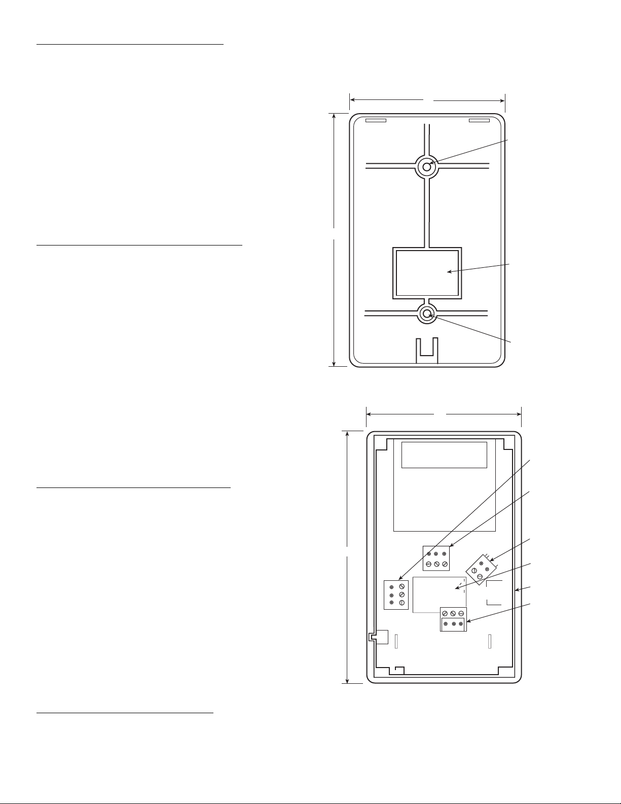
Physical components of the 45XC fan-powered zone
mixing unit is detailed in Fig. 5. Figure 6 shows 45XC fanpowered zone mixing unit dimensions and weight data.
CEILING PLENUM
RETURN AIR
DUCT
CONTROL
ENCLOSURE
42 in. MINIMUM - SIZE 04
54 in. MINIMUM - SIZE 07
LOW AND HIGH
PRESSURE PORT*
RAISED FLOOR
*Installation is shown for a single unit in a multiple unit/common plenum application.
High and low pressure ports piped to a discharge plenum. Refer to Fig. 2.
SUPPLY AIR
TEMPERATURE
PROBE
SUPPLY DUCT
Fig. 5 — 45XC Fan-Powered Zone Mixing Unit Physical Details
6

1/2" DIA.
H
X
Y
D
PRIMARY
AIR INLET
W
DAMPER SHAFT
DD
1/2"
20"
ALLOW AT LEAST
24" CLEARANCE
FOR CONTROLS
J 11 7/8"
6 1/4"
A
B 1-1/2"
INLET VIEW
45XC UNIT SIZE UNIT WEIGHT (lb) FILTER SIZE (in.) FILTER P/N FILTER KIT P/N
4 209 17 x 17 x 1 102649-1717 3503341717
7 269 22 x 19 x 1 102649-2219 3503342219
INLET
UNIT
SIZE
*Estimated for rpm/torque controlled motor, at 0.1 in. wg static pressure under floor.
NOTE: Inlet Size: 6-10, DD = 3
SIZE
(in.)
4
7
PRI.
CFM
6 500 1200 1700
8900 1200 21001/2361/8361/8181/16151/815 77/811 14 9 631/831/
10 1400 1200 26001/2361/8361/8181/16151/815 97/811 14 9 731/831/
12 2100 1200 33001/2361/8361/8181/16151/815 117/811 14 9831/
10 1400 2500 3900 1 42
12 2100 2500 4600 1 421/8461/8201/16201/817 117/815 17 10 8 51/241/
14 2800 2500 5300 1 421/8461/8201/16201/817 137/815 17 10 10 51/
16 3700 2500 6200 1 421/8461/8201/16201/817 157/815 17 10 101/451/
FA N
CFM*
7
/8in. Inlet Size: 12-16, DD = 57/8in.
1-1/4"
MAX
FLOW
RECIRCULATED
AIR INLET
MOUNTING BRACKET - (4 PLCS)
SEE OPTIONAL FEATURES BELOW
PLAN VIEW – LEFT HAND UNIT
RIGHT HAND UNITS AVAILABLE - CONTROLS NOT SHOWN
HP
LWH
1
/2361/8361/8181/16151/815 57/811 14 9 631/831/
1
/8461/8201/16201/817 97/815 17 10 7 51/241/
L
Recirc. Air
AB FG
Fig. 6 — 45XC Fan Powered Zone Mixing Unit Physical Data and Dimensions
45XC Hardware — The 45XC fan-powered mixing unit
contains the 33ZCPLNCTL zone controller.
Figure 7 shows the zone controller physical details.
SUPPLY-AIR TEMPERATURE (SAT) SENSOR (Fig. 9) —
The zone controller must be connected to a field-supplied supply air temperature (SAT) sensor (P/N 33ZCSENSAT) to monitor the temperature of the air delivered by the fan coil.
45XC Field-Supplied Hardware — Each 45XC fan-
powered zone mixing unit requires the following field-supplied
components to complete its installation:
• transformer — 24 vac, 40 va (standard applications)
• contactors (as required for electric heat)
1
•
/4-in. OD flame retardant polyethylene tubing (length not
toexceed25ft)
• space temperature sensor (33ZCT55SPT, 33ZCT56SPT, or
33ZCT57SPT)
• supply-air temperature sensor (33ZCSENSAT) with two
no. 10 x
supply duct)
• primary-air temperature sensor
• indoor-air quality (CO
• relative humidity sensor (optional)
SPACE TEMPERATURE SENSOR (Fig. 8) — Each
33ZCPLNCTL zone controller requires a field-supplied
Carrier space temperature sensor. There are three sensors
available for this application:
• 33ZCT55SPT, space temperature sensor with override
button
• 33ZCT56SPT, space temperature sensor with override
button and set point adjustment
1
/2-in. sheet metal screws (to secure SAT sensor to
) sensor (optional)
2
PRIMARY-AIR TEMPERATURE SENSOR (PAT)
(Optional) — A field-supplied, primary air temperature (PAT)
sensor (P/N 33ZCSENPAT) is used on a zone controller that is
functioning as a linkage master for a non CCN/linkage compatible air source. See Fig. 10.
INDOOR-AIR QUALITY (CO
indoor air quality sensor is required for IAQ monitoring.
Three different CO2sensors are available for zone CO2level
monitoring.
• The 33ZCSENCO2 sensor is an indoor, wall-mounted sensor with an LED (light-emitting diode) display.
• The 33ZCT55CO2 sensor is an indoor, wall-mounted sensor without display. The CO
temperature sensor with override button.
• The 33ZCT56CO2 sensor is an indoor, wall-mounted sensor without display. The CO
temperature sensor with override button and temperature
offset.
RELATIVE HUMIDITY SENSOR (Fig. 12) — The relative
humidity sensor (P/N 33AMSENRHS000) is an indoor, wallmounted sensor and is required for zone humidity control
(dehumidification).
• 33ZCT57SPT, space temperature sensor with override button, set point adjustment, and manual fan speed control
DISCHARGE
DIMENSIONS (in.)
Discharge
D
G
Z
F 2 9/16"
DISCHARGE VIEW
XY Z J
8
8
8
31/
8
8
8
8
41/
8
2
41/
2
8
)SENSOR(Fig.11)—An
2
sensor also includes a space
2
sensor also includes a space
2
7

0
HF23BJ042
Made in Switzerland
by Belimo Automation
LR 92800
NEMA 2
LISTED
94D5
TENP IND &
REG. EQUIP.
Class 2 Supply
5K
WIP
yel
blu
ora
35 in-lb (4 Nm)
80...110s
24VAC/DC
50/60 Hz
3VA 2W
COM
1
2
red wht
blk
15
LOW
1
®
3
ZONE Controller
Part Number: 33ZCPLNCTL
S/N:
Bus#:
Element#:
Unit#:
HIGH
US
C
1
J6
2
1
J7
3
®
1
J8
3
SEC DMP
J6
1
CCW
COMCWHEAT1
24VAC
HEAT2
FAN AC
FAN
24VAC
N/A
HEAT3
CW
COM
COW
6
RH/IAQ
GND
SECFLOW
J4
+10V
DMPPOS
GND
TEST
GND
1
1
CCN
J2A
3
1
3
+
G
-
J1
+24V
SPT
GND
SAT
T56
GND
PAT
REMOTE
J3
24VAC
16
2
1
+
LEN
G
-
J2B
3
SRVC
+
-
G
Fig. 7 — 45XC Fan-Powered Zone Mixing Unit Controller Physical Details (33ZCPLNTCTL)
Cool
Warm
Fig. 8 — Space Temperature Sensor (P/N 33ZCT56SPT Shown)
.08
.39
FOAM GASKET
3.90
.40'' O.D.
.250 ±.01 Dia
.175 DIA
x .600
3.00
PLENUM RATED CABLE
114'' ±6
5.5 ±.5
NOTE: Dimensions are in inches.
Fig. 9 — Supply Air Temperature Sensor (33ZCSENSAT)
8

Fig. 10 — Primary Air Temperature Sensor
(33ZCSENPAT)
5.625
(14.3)
3.25
(8.3)
NOTE: Dimensions are in inches. Dimensions in () are in
centimeters.
1.125
(2.9)
5
(12.7)
0.25
(0.8)
Fig. 11 — Indoor Air Quality (CO2) Sensor
(33ZCSENCO2)
Fig. 12 — Wall-Mounted Relative Humidity Sensor
(33AMSENRHS000)
45XC Fan-Powered Zone Mixing Box Installation
STEP 1 — SELECT LOCATION
1. Units should be installed so that they do not come in contact with obstacles such as rigid conduit, sprinkler piping,
Greenfield flexible metal covering, or rigid pneumatic
tubing; such contact can transmit vibration to the building
structure, causing objectionable low frequency noise.
2. Units should never be installed tightly against concrete
slabs or columns, as vibration transmission is amplified in
this condition.
3. Fan-powered terminals require sufficient clearance for
servicing the blower/motor assembly from the bottom of
the unit, low voltage controls from the side and line
voltage motor controls or electric heat (if equipped) from
the rear (discharge end) of the unit. See Fig. 6.
Bottom access panel removal requires a minimum of
3-in. minimum clearance, in addition to substantial horizontal clearance, to slide the access panel out of the way
for service. Actual horizontal dimensions will vary due to
varying access panels for different sized units. See unit
submittal drawings for detailed information.
NOTE: Be certain that accommodations for panel removal of unit casings are large enough to allow adequate
internal service room once the panels are removed.
A clearance of 18 in. is recommended for control enclosure access. Unit control enclosure will vary depending
on which control package is used. Control enclosure
location is specified on unit submittals. Low voltage
enclosure covers are removable, not hinged.
A clearance of 36 in. is recommended for line voltage
motor controls and electric heat control access. High voltage motor controls or electric heat control access is
supplied with hinged access doors for units with fused
disconnect. Specific location is indicated on the unit
submittal.
These recommendations do not supersede NEC (National
Electrical Code) or local codes that may be applicable.
Adherence to these codes are the responsibility of the
installing contractor.
4. Whenever possible, fan-powered boxes should be
installed over halls or passageways (rather than over
occupied spaces) in order to limit the sound reaching
occupants.
STEP 2 — POSITION UNIT
1. When moving boxes, use appropriate material handling
equipment and avoid contact with shaft extensions, controls, wiring, piping, heaters, and control boxes.
2. Raise unit to position using safe mechanical equipment
and support until hanging means are attached and box is
level.
STEP 3 — INSTALL UNIT
1. Install field-supplied eyebolts, straphangers or bolt rod
supports as desired. Figure 13 illustrates possible 45XC
unit suspension methods. A typical underfloor installation
is shown in Fig. 14.
2. Care should be taken to use hanging materials of sufficient stiffness and strength, rigidly attached to the unit.
Straps should not be located on coil flanges, electric heat
sections, or control boxes. When using trapeze supports,
avoid areas where access is required to side mounted
controls, or side or bottom access doors. For best installation with trapeze supports, provide elastomeric material
between unit and supports.
3. Hangers should be securely attached to bar joist or
mounting anchors properly secured to building structure
with lugs or poured-in-place hangers. Percussion nails are
not considered adequate anchors.
9

STEP 4 — MAKE DUCT CONNECTIONS
1. Check that the pressure pick-up in primary air collar is
located properly and that air supply duct connections are
airtight. Install supply ductwork on unit inlet collar,
following all accepted medium-pressure duct installation
procedures. Seal joints against leakage.
NOTE: For maximum efficiency in controlling radiated
noise in critical applications, inlet ducts should be fabricated of 24-gage minimum sheet metal in place of flex
connections. Flex duct is extremely transparent to radiated sound; consequently high inlet static pressure (Ps) or
sharp bends with excessive pressure drop can cause a radiated noise problem in the space. If flex duct is used, it
should be limited to the connection between the distribution duct and the boot diffuser.
2. Install the discharge duct, being careful not to reduce the
face area of any electric heat section until several diameters away from the unit. It is strongly recommended that
lined discharge duct be used downstream of the unit.
Insulate duct as required.
3. Fan boxes should not be attached to octopus sections
immediately downstream of the unit.
4. Install optional return-air filters before operating the unit.
5. Leave construction filters supplied with the box in place
until installation is complete and building is cleared for
occupancy.
STEP 5 — POWER WIRING
Disconnect electrical power before wiring or servicing the
unit. All disconnect switches on the terminal (if equipped)
should be in the OFF position while making power connections. Electrical shock, personal injury, or damage to the
zone controller can result.
1. All power wiring must comply with local codes and with
NEC ANSI/NFPA (American National Standards
Institute/National Fire Protection Association) 70-1981.
Disconnect switches are optional equipment. Electrical,
control and piping diagrams are shown on the exterior
labeling or on a diagram inside the control and highvoltage enclosure covers, unless otherwise specified in
the order write-up. All units are wired for a single point
electrical connection to the fan and electric heater (if
equipped). Electric heaters provided by Carrier are
balanced by kW per stage. The installing electrician
should rotate incoming electric service by phase to help
balance overall building load.
2. All field wiring must be provided with a safety disconnect per NEC 424-19, 20, and 21.
3. Units with electric heat should use copper wires rated at
least 125% of rating plate amperage. Refer to the unit’s
rating label and minimum supply circuit amps.
4. Observe wiring diagram and instructions attached to the
unit. A Wye power source with a fourth (neutral) wire in
addition to the full sized ground wire is required for
480-v, 3-phase units. All units must be grounded as
required by NEC 424-14 and 250. See Fig. 15A and 15B.
ACCESSORY
HANGER
SUPPORT
ROD
FIELD-SUPPLIED
BRACKET
HANGER
DO NOT SUSPEND UNIT BY
TRAPEZE HANGERS THAT
INTERFERE WITH THE
UNIT ACCESS PANEL
Fig. 13 — Typical 45XC Support Methods
10

ROOM
SENSOR
45XC
FAN POWERED
ZONE MIXING
BOX
Fig. 14 — Typical Underfloor Installation — 45XC Fan-Powered Mixing Box
35 BF-R
SWIRL DIFFUSER
11

LEGEND
Factory Piping
Factory Wiring
Fig. 15A — 45XC Zone Controller Wiring — Control Package 4840
Field Wiring
to the fully closed position. Mount actuator over damper shaft and
secure to shaft enclosure. Engage clutch and rotate damper CCW to
AFS — Airflow Switch
COM — Common
CCW — Counterclockwise
CW — Clockwise
DMPPOS — Damper Position
ECM — Electronically Commutated Motor
GND — Ground
N.O. — Normally Open
PAT — Primary Air Temperature Sensor
SAT — Plenum Temperature Sensor
SPT — Space Temperature Sensor
UL — Underwriter’s Laboratories
NOTES:
the fully open position.
1. Verify actuator bushing is in the full CW position. Rotate damper CW
2. Use insulated quick connects.
Electric shock may result. Disconnect unit prior to servicing unit.
3. These controls have been wired to comply with UL-1995.
12

LEGEND
Factory Piping
Factory Wiring
Field Wiring
AFS — Airflow Switch
COM — Common
CCW — Counterclockwise
CW — Clockwise
DMPPOS — Damper Position
ECM — Electronically Commutated Motor
GND — Ground
N.O. — Normally Open
PAT — Primary Air Temperature Sensor
SAT — Plenum Temperature Sensor
SPT — Space Temperature Sensor
UL — Underwriter’s Laboratories
Electric shock may result. Disconnect unit prior to servicing
CW to the fully closed position. Mount actuator over damper
shaft and secure to shaft enclosure. Engage clutch and rotate
damper CCW to the fully open position.
NOTES:
1. Verify actuator bushing is in the full CW position. Rotate damper
2. Use insulated quick connects.
unit.
3. These controls have been wired to comply with UL-1995.
13
Fig. 15B — 45XC Zone Controller Wiring — Control Package 4841

45XC Sensor Installation
GENERAL SENSOR INSTALLATION — The sensor should
be mounted:
• on an internal wall near a return air grille or duct
• at least 3 ft from any corner, 2 ft from an open doorway and
4 to 6 ft from the floor
• proximal to the wiring egress on the wall
• where temperature operating limits are 32 to 122 F
The sensor should NOT be mounted:
• close to a window, on an outside wall, or next to a door
leading to the outside
• close to or in direct airflow of areas such as open windows,
drafts or over heat sources
• in areas with poor air circulation, such as behind a door or in
an alcove where there are dramatic temperature fluctuations
or moisture accumulation
• where it is influenced by supply air as the sensor will give
an inaccurate reading
• where it may be exposed to direct occupant breathing, such
as near water coolers or coffee machines.
SPACE TEMPERATURE SENSOR INSTALLATION —
A space temperature sensor must be installed for each zone
controller. There are three types of SPT sensors available used
with the 33ZCPLNCTL controller: 33ZCT55SPT space temperature sensor with timed override button, 33ZCT56SPT
space temperature sensor with timed override button and set
point adjustment, and 33ZCT57SPT space temperature sensor
with timed override button, set point adjustment, and manual
fan speed control. See Fig. 8 and 16.
The space temperature sensor is used to measure the build-
ing interior temperature and should be located on an interior
building wall. The sensor wall plate accommodates the NEMA
(National Electrical Manufacturers Association) standard 2 x
4 in. junction box. The sensor can be mounted directly on the
wall surface if acceptable by local codes.
Do not mount the sensor in drafty locations such as near air
conditioning or heating ducts, over heat sources such as baseboard heaters or radiators, or directly above wall-mounted
lighting dimmers. Do not mount the sensor near a window
which may be opened, near a wall corner, or a door. Sensors
mounted in these areas will have inaccurate and erratic sensor
readings.
The sensor should be mounted approximately 5 ft from the
floor, in an area representing the average temperature in the
space. Allow at least 4 ft between the sensor and any corner
and mount the sensor at least 2 ft from an open doorway.
The sensor consists of the following hardware:
1 — sensor top
1 — sensor base
1 — mounting plate
2 — machine screws (6 x 32)
2 — locking screws
Install the sensor as follows (see Fig. 16):
1. Locate the two Allen type screws at the bottom of the
sensor.
2. Turn the two screws clockwise to release the cover from
the sensor wall mounting plate.
3. Lift the cover from the bottom and then release it from
the top fasteners.
4. Feed the wires from the electrical box through the opening in the center of the sensor mounting plate.
5. Usingtwono.6-32x1machinescrews(providedwith
the sensor), secure the sensor to the electrical box.
NOTE: Sensor may also be mounted directly on the wall
using2plasticanchorsand2sheetmetalscrews
(field-supplied).
6. Use 20-gage wire to connect the sensor to the controller.
The wire is suitable for distances of up to 500 ft. Use a
three-conductor shielded cable for the sensor and set
point adjustment connections. The standard CCN communication cable may be used. If the set point adjustment
(slidebar) is not required, then an unshielded, 18-gage or
20-gage, two-conductor, twisted pair cable may be used.
The CCN service jack requires a separate, shielded CCN
communication cable. Always use separate cables
for CCN communication and sensor wiring. (Refer to
Fig. 17-19 for wire terminations.)
7. Replace the cover by inserting the cover at the top of the
mounting plate first, then swing the cover down over the
lower portion. Rotate the two Allen head screws counterclockwise until the cover is secured to the mounting plate
and locked in position.
NOTE: Clean sensor with damp cloth only. Do not use
solvents. See Table 1 for resistance vs temperature data.
Before performing service or maintenance operations on
the system, turn off main power switches to the unit.
Electric shock can cause personal injury.
NOTE: Dimensions are in inches.
Fig. 16 — Space Temperature Sensor and
Wall-Mounted Humidity Sensor Mounting
14

Wiring the Space Temperature Sensor
(33ZCT55SPT,
33ZCT56SPT, 33ZCT57SPT) — The sensor wiring has the
following requirements:
• Power requirements: 18 to 36 vac RMS 50/60 Hz at 4 va.
• All system wiring must be in compliance with all applicable
local and national codes.
• A dedicated power supply is required for this sensor.
• All sensor wiring should be color-coded for ease of mainte-
nance and service.
• Wiring should be 18 to 22 AWG (American Wire Gage)
stranded wire (20 AWG is recommended).
To wire the sensor, perform the following (see Fig. 17-19):
1. Identify which cable is for the sensor wiring.
2. Strip back the jacket from the cables at least 3 inches.
1
Strip
/4-in. of insulation from each conductor. Cut the
shield and drain wire from the sensor end of the cable.
3. Connect the sensor cable as follows:
a. Connect one wire from the cable (RED) to the SPT
terminal on the controller. Connect the other end of
the wire to the left terminal on the SEN terminal
block of the sensor.
b. Connect another wire from the cable (BLACK) to
the GND terminal on the controller. Connect the
other end of the wire to the remaining open terminal on the SEN terminal block (COM on
33ZCT57SPT).
c. On 33ZCT56SPT and 33ZCT57SPT thermostats,
connect the remaining wire (WHITE/CLR) to the
T56 terminal on the controller. Connect the other
end of the wire to the SET terminal on the sensor.
d. In the control box, install a no. 10 ring-type crimp
lug on the shield drain wire. Install this lug under
the mounting screw of the zone controller.
e. On 33ZCT56SPT thermostats, install a jumper
between the two center terminals (right SEN and
left SET). See Fig. 18.
f. On 33ZCT57SPT thermostats, a separate
3-conductor, shielded cable is used to connect the
fan speed wiring. Connect the SPD terminal on the
thermostat to the SPEED terminal on the zone controller. Use the white/clear wire. Connect the COM
terminal on the thermostat to the GND terminal on
the zone controller. Use the black wire. Connect
the 10V terminal on the thermostat to the +10V
terminal on the zone controller. Use the red wire.
In the control box, install a no. 10 ring-type crimp
lug on the fan speed wiring shield drain wire.
Install this lug under the mounting screw of the
zone controller.
Wiring the CCN Communication Service Jack
—See
Fig. 17-19. To wire the service jack, perform the following:
1. Strip back the jacket from the CCN communication
cable(s) at least 3 inches. Strip
1
/4-in. of insulation from
each conductor. Remove the shield and separate the drain
wire from the cable. Twist together all the shield drain
wires and fasten them together using a closed end crimp
lug or a wire nut. Tape off any exposed bare wire to
prevent shorting.
2. Connect the CCN + signal wire(s) (RED) to Terminal 5.
3. Connect the CCN – signal wire(s) (BLACK) to
Terminal 2 .
4. Connect the CCN GND signal wire(s) (WHITE/CLR) to
Terminal 4 .
Before wiring the CCN connection, refer to Connect the
CCN Communication Bus section for communication bus wiring and cable selection. The cable selected must be identical to
the CCN communication bus wire used for the entire network.
The other end of the communication bus cable must be
connected to the remainder of the CCN communication bus. If
the cable is installed as a T-tap into the bus, the cable length
cannot exceed 50 ft. No more than 10 T-taps are allowed
per bus. Wire the CCN service jack of the sensor in a daisy
chain arrangement with other equipment. See Fig. 20. Refer to
the Connect to the CCN Communication Bus section for additional details.
SW1
2
3
SEN
45
61
RED(+)
WHT(GND)
BLK(-)
BLK (GND)
RED (SPT)
CCN COM
SENSOR WIRING
Fig. 17 — Space Temperature Sensor Wiring
(33ZCT55SPT)
2
3
SEN
SW1
Cool Warm
45
61
RED(+)
WHT(GND)
BLK(-)
SET
WHT
(T56)
BLK (GND)
RED (SPT)
CCN COM
SENSOR WIRING
JUMPER
TERMINALS
AS SHOWN
Fig. 18 — Space Temperature Sensor Wiring
(33ZCT56SPT)
15

WHITE (SPEED)
3-CONDUCTOR
SHIELDED CABLE
LEGEND
CCN — Carrier Comfort Network®
SW1 — Switch
Set Point — Set Point Adjust
NOTE: Do not connect white wire to SET terminal if set point adjustment is not needed.
3-CONDUCTOR
SHIELDED CABLE
Fig. 19 — Space Temperature Sensor Wiring (33ZCT57SPT)
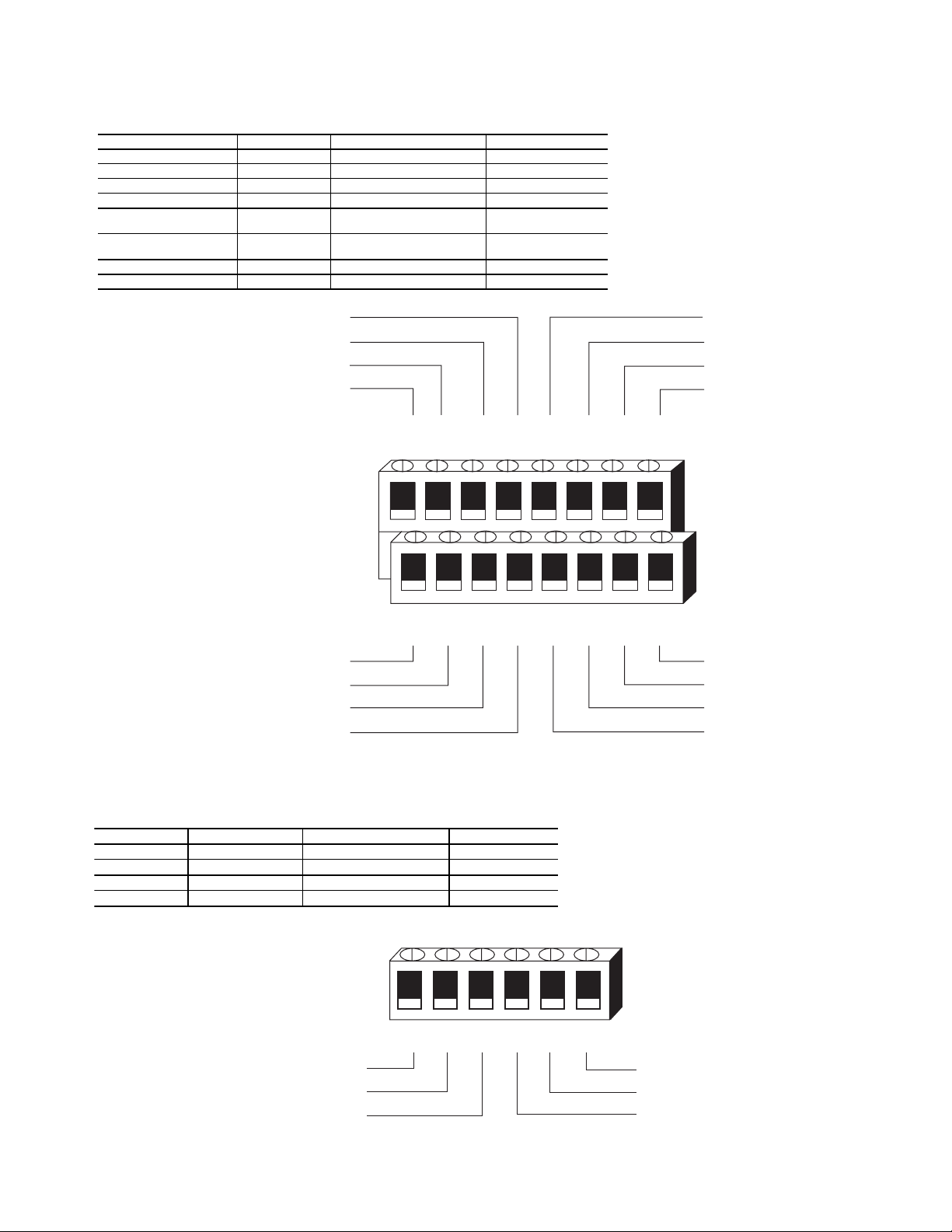
Table 1 — Thermistor Resistance vs Temperature Values for Space Temperature Sensor,
Return-Air Temperature Sensor, and Supply-Air Temperature Sensor
TEMP (C) TEMP (F) RESISTANCE (Ohms)
0 32 32,651
5 41 25,395
10 50 19,903
15 59 15,714
20 68 12,494
25 77 10,000
30 86 8,056
35 956,530
40 104 5,325
45 113 4,367
50 122 3,601
16

Wiring when distance between fan coil controller and space temperature sensor is 50 feet or less:
50 FT. MAXIMUM
FAN COIL
PERIMETER
CONTROLLER
3 COND COMM CABLE (TYP)
2 COND TWISTED
CABLE OR 3 COND
CABLE (TEMP
SENSOR WIRING) (TYP)
45KC
FAN COIL UNIT
CCN COMM BUS
Warm
Cool
SPACE
TEMPERATURE
SENSOR
Wiring when distance between fan coil controller and space temperature sensor is greater than 50 feet:
Warm
Cool
CCN COMM BUS
2 COND TWISTED
CABLE OR 3 COND
CABLE (TEMP
SENSOR WIRING) (TYP)
Warm
Cool
SPACE
TEMPERATURE
SENSOR
DISTANCE GREATER
THAN 50 FT.
Fig. 20 — Communication Bus Wiring (42KC Perimeter Fan Coil Zone Controller Shown)
Warm
Cool
17

SUPPLY-AIR TEMPERATURE (SAT) SENSOR INSTALLATION — The SAT sensor is required and must be installed
in the fan coil air outlet. The part number is 33ZCSENSAT.
The SAT sensor probe is 6 inches in length. See Fig. 9.
When using a ducted supply, the supply-air temperature
sensor should be located in the supply duct downstream of the
discharge of the fan coil to allow good mixing of the supply
airstream.
See Fig. 21 for mounting location. See Fig. 22 for mounting
hole requirements.
Disconnect electrical power before wiring the zone controller. Electrical shock, personal injury, or damage to the zone
controller can result.
Do not run sensor or relay wires in the same conduit or
raceway with Class 1 AC service wiring. Do not abrade,
cut, or nick the outer jacket of the cable. Do not pull or
draw cable with a force that may harm the physical or
electrical properties. Avoid splices in any control wiring.
Damage to the 33ZCPLNCTL zone controller can result.
Perform the following steps to connect the SAT sensor to
the zone controller:
1. Locate the opening in the control box. Pass the sensor
probe through the hole.
1
2. Drill or punch a
/2-in. hole in the fan coil unit. See
Fig. 22.
3. Use two field-supplied, self-drilling screws to secure the
sensor probe to the fan coil unit.
4. Connect the sensor leads to the zone controller’s wiring
harness terminal board at the terminals labeled SAT
(RED) and GND (BLK).
Perform the following steps if state or local code requires
the use of conduit, or if sensor installation requires a cable
length of more than 8 ft:
1. Secure the probe to the fan coil unit with two fieldsupplied self-drilling screws.
2. If extending cable length beyond 8 ft, use plenum rated,
20 AWG, twisted pair wire.
3. Connect the sensor leads to the zone controller’s wiring
harness terminal board at the terminals labeled SAT
(RED) and GND (BLK).
4. Neatly bundle and secure excess wire.
INDOOR-AIR QUALITY (CO
) SENSOR INSTALLA-
2
TION — The indoor-air quality (CO2) sensor accessory monitors carbon dioxide levels, which provide information used to
monitor indoor air quality. Three types of sensors are provided.
The wall sensor can be used to monitor the conditioned air
space. Sensors use infrared technology to measure the levels of
CO
present in the air. The wall sensor is available with or
2
without an LCD readout to display the CO
Fig. 11.
level in ppm. See
2
Sensor accessory descriptions and part numbers are shown
in Table 2. To mount the sensor, refer to the installation instructions shipped with the accessory kit.
Table 2 — CO
CO2SENSOR
ACCESSORY
PA RT N U MB ER S
33ZCSENCO2 Wall Mount Sensor (with display)
33ZCT55CO2
33ZCT56CO2
The CO
sensors listed in Table 3 are factory-set for a range
2
Sensor Accessories
2
DESCRIPTION
Wall Mount Sensor with 33ZCT55SPT
space temperature sensor (no display)
Wall Mount Sensor with 33ZCT56SPT
space temperature sensor and set point
adjustment (no display)
of 0 to 2000 ppm and a linear voltage output of 0 to 10 vdc.
Refer to the instructions supplied with the CO
sensor for
2
electrical requirements and terminal locations.
To accurately monitor the quality of the air in the conditioned air space, locate the sensor near a return air grille (if
present) so it senses the concentration of CO
leaving the
2
space. The sensor should be mounted in a location to avoid
direct breath contact.
Do not mount the CO
sensor in drafty areas such as near
2
supply ducts, open windows, fans, or over heat sources. Allow
at least 3 ft between the sensor and any corner. Avoid mounting
the sensor where it is influenced by the supply air; the sensor
gives inaccurate readings if the supply air is blown directly
onto the sensor or if the supply air does not have a chance
to mix with the room air before it is drawn into the return
airstream.
APROX
2 FT
SUPPLY
DUCT
TYPICAL
FAN COIL UNIT
HC
SUPPLY
AIR SENSOR
LEGEND
HC — Heating Coil
Fig. 21 — Supply Air Temperature Sensor
Mounting Location (42KC)
3.00
1.50
ø0.50
CLEARANCE HOLE
ENGAGEMENT HOLE FOR
#10 SHEET METAL SCREW (2)
Fig. 22 — Supply Air Temperature
Sensor Mounting
18

Indoor-Air Quality Sensor Wiring
— To wire the sensors
after they are mounted in the conditioned air space or outdoor
location, see Fig. 23 and the instructions shipped with the
sensors. For each sensor, use two 2-conductor 18 AWG
twisted-pair cables (unshielded) to connect the separate isolated 24 vac power source to the sensor and to connect the sensor
to the control board terminals. To connect the sensor to the
control board, identify the positive (0-10 VDC) and ground
(SIG COM) terminals on the sensor. Connect the –10 VDC terminal to terminal IAQ and connect the SIG COM terminal to
terminal GND.
RELATIVE HUMIDITY SENSOR (WALL-MOUNTED)
INSTALLATION — The relative humidity sensor accessory
is installed on an interior wall to measure the relative humidity
of the air within the occupied space. See Fig. 12.
Theuseofastandard2x4in.electricalboxtoaccommodate the wiring is recommended for installation. The sensor can
be mounted directly on the wall, if acceptable by local codes.
If the sensor is installed directly on a wall surface, install the
humidity sensor using 2 screws and 2 hollow wall anchors
(field-supplied); do not overtighten screws. See Fig. 16.
Do NOT clean or touch the sensing element with chemical
solvents; they can permanently damage the sensor.
The sensor must be mounted vertically on the wall. The
Carrier logo should be oriented correctly when the sensor is
properly mounted.
DO NOT mount the sensor in drafty areas such as near heating or air-conditioning ducts, open windows, fans, or over heat
sources such as baseboard heaters, radiators, or wall-mounted
light dimmers. Sensors mounted in those areas will produce
inaccurate readings.
Avoid corner locations. Allow at least 4 ft between the
sensor and any corner. Airflow near corners tends to be
reduced, resulting in erratic sensor readings.
Sensor should be vertically mounted approximately 5 ft up
from the floor, beside the space temperature sensor.
For distances up to 500 feet, use a 3-conductor, 18 or
20 AWG cable. A CCN communication cable can be used,
although the shield is not required. The shield must be removed
from the sensor end of the cable if this cable is used. See
Fig. 24 for wiring details.
The power for the sensor is provided by the control board.
The board provides 24 vdc for the sensor. No additional power
source is required.
FRESH
AIR
DAMPER
FAN
ON
FAN A C
LOW
MED
HIGH
24VAC
OAD
RH
GND
IAQ
+10V
SPEED
GND
CONDSW
GND
R
+
W
GND
B
-
+24V DC
SPT
GND
SAT
T56
GND
CNGOVR
RMT/FS
R
W
B
87
21
24VAC
LINE VOLTAGE
SEPARATE
POWER
SUPPLY
REQUIRED
NOT USED
CCN
COMMUNICATIONS
VALV E
DX1
COM
VALV E
DX2
HEAT1
24VAC
HEAT2
Fig. 23 — CO2Sensor Wiring (42KC Controller Shown)
19
CCN
COMMUNICATIONS
24 VAC
EQUIPMENT GROUND
LINE
VOLTAGE

To wire the sensor, perform the following:
1. At the sensor, remove 4-in. of jacket from the cable. Strip
1
/4-in. of insulation from each conductor. Route the cable
through the wire clearance opening in the center of the
sensor.
2. Connect the RED wire to the sensor screw terminal
marked (+).
3. Install one lead from the resistor (supplied with the sensor) and the WHITE wire into the sensor screw terminal
marked (–). After tightening the screw terminal, test the
connection by pulling gently on the resistor lead.
4. Connect the remaining lead from the resistor to the
BLACK wire and secure using a field-supplied closed
end type crimp connector or wire nut.
5. Using electrical tape, insulate any exposed resistor lead to
prevent shorting.
6. At the control box, remove the jacket from the cable.
7. Strip
1
/4-in. of insulation from each conductor.
8. Connect the RED wire to terminal 24 VDC on the control
board.
NOTE: The 24 VDC terminal is used for rh sensor wiring
only.
9. Connect the BLACK wire to terminal GND on the
control board.
10. Connect the WHITE/CLEAR wire to terminal RH on the
control board.
11. Connect shield to earth ground (if shielded wire is used).
HUMIDITY SENSOR
RED
WHITE
BLACK
SHIELD
(IF USED)
+24V DC
RH
SPT
GND
GND
IAQ
SAT
+10V
SPEED
GND
GND
R
+
W
GND
B
-
J1
T56
GND
CNGOVR
RMT/FS
R
W
B
1
2
3
VALVE
DX1
COM
VALVE
DX2
HEAT1
24VAC
HEAT2
FRESH
AIR
DAMPER
FAN
ON
FAN A C
LOW
MED
HIGH
24VAC
OAD
CONDSW
Fig. 24 — Humidity Sensor Wiring (42KC Controller Shown)
+
-
499
NOT USED
CCN
COMMUNICATIONS
CCN
COMMUNICATIONS
24 VAC
LINE
VOLTAGE
EQUIPMENT
GROUND
20

AND SPACE TEMPERATURE SENSORS (Optional) —
CO
2
The CO
and space temperature sensors are comprised of two
2
sensors housed in one unit. They are designed to monitor
carbon dioxide (CO2) levels in the air and measure the interior
building temperature.
Two models are available: P/N 33ZCT55CO2, and
P/N 33ZCT56CO2, which has a set point adjustment potentiometer. Both models include a push-button override that may
be disabled through controller software. See Table 3 for sensor
specifications. To convert the CO
CO
sensor, the duct-mounted aspirator (33ZCASPCO2) will
2
sensor into a duct-mounted
2
NOTE: There are 2 locking screws provided on the bottom of
the cover for security. A special tool is required to remove and
install the cover if the locking screws are used.
The sensor consists of the following hardware:
1 — sensor top
1 — sensor base
1 — mounting plate
2 — machine screws (6 x 32)
2 — locking screws
need to be purchased.
Refer to the instructions supplied with the CO
electrical requirements and terminal locations. The zone
controller requires 24 vac 25 va transformer to provide power
to the sensor.
sensor for
2
Before performing service or maintenance operations on
the system, turn off main power switches to the unit.
Electric shock can cause personal injury.
IMPORTANT: The CO2and space temperature sensor
should be wall-mounted in the occupied space to accurately measure the ventilation delivered to that zone.
Do NOT mount the sensor in the return air duct.
Table 3 — Performance Specification (P/N 33ZCT55CO2 and 33ZCT56CO2)
FEATURE SPECIFICATION
Sensing Method Single Beam Absor ption Infrared™
Sample Method Diffusion
Measurement Range 0to2000ppm
Sensitivity ± 20 ppm
Accuracy ± 100 ppm
Pressure Dependency 0.13% of reading per mmHg
Response Time 0 to 90% Step Change <2 minutes
Warm-Up Time at 77 F (25 C) <2 minutes
Operating Conditions 32 to 122 F (0° to 50 C)
Storage Temperatures –4 to +158 F (–20to70C)
Agency Certification FCC Part 15 Class B/CE/CA Energy Commission
Calibration/Interval Lifetime self-calibrating after 14 days of run time.*
Power 18-30 vac RMS, 50/60 Hz —halfwave rectified (dedicated)
Analog CO
Temperature Sensor 10 KΩ Thermistor, 10 KΩ ± 2.5% at 77 F (25 C)
Temperature Control (P/N 33ZCT56CO2 only) Equipped with a slide potentiometer.
Override Control Equipped with a push button that, when depressed, shorts out its internal thermistor.
Reliability Meets applicable Carrier reliability requirements
KΩ — Kilo-ohm (1000 ohms)
RH — Relative Humidity
RMS — Root Mean Square
TEMA — Time Extended Measurement
Output 4-20 mA (Rlmax = 500 Ohms) and 0-10 V(Source 100 mA, Sink 10 mA)
2
LEGEND *Automatic background calibration (ABC Logic™) is a patented self-
Patented TEMA self calibration software and 10K temperature sensor
60 to 90 F: 760 mmHg (15 to 32 C)
0to99% RH, non-condensing
18-42 VDC polarity protected (dedicated)
1.75 VA maximum average power
2.75 VA peak power
Positions Resistance
Left (Stop) 0 K(+5 K)
Right (Stop) 100 K±10 K
calibration procedure that is designed to be used in applications where
CO
concentrations will drop to outdoor ambient conditions (approxi-
2
mately 400 ppm) at least 3 times in a 14-day period (typically during
unoccupied periods).
21
Step 1 — Space Temperature Sensor Location
— The sensor
should be mounted:
• on an internal wall near a return air grille or duct
• at least 3 ft from any corner, 2 ft from an open doorway and
4 to 6 ft from the floor
• proximal to the wiring egress on the wall
• where temperature operating limits are 32 to 122 F
The sensor should NOT be mounted:
• close to a window, on an outside wall, or next to a door leading to the outside
• close to or in direct airflow of areas such as open windows,
drafts or over heat sources
• in areas with poor air circulation, such as behind a door or in
an alcove in areas where there are dramatic temperature
fluctuations or moisture accumulation
• where it is influenced by supply air as the sensor will give
an inaccurate reading
• where it may be exposed to direct occupant breathing, such
as near water coolers or coffee machines.
Step 2 — Mounting the Space Temperature Sensor
—The
sensor can be mounted on a surface, wall or in a junction box.
See Fig. 25-28.
NOTE: Before mounting the sensor, disassemble the sensor
into three parts. See Fig. 27.
Surface or Wall Mounting
1. Place the mounting plate on the wall. Mark the desired
location of the two mounting holes on the wall through
the holes in the mounting plate. See Fig. 25.
2. Pull the wires through the wire hole in the middle of the
mounting plate.
3. Drill two mounting holes in the wall in the location
marked in Step 1.
4. Mount the sensor mounting plate with two wood screws
and anchors (field-supplied).
Junction Box Mounting
1. Run wires through knockout in a 2x4in.junctionbox
(field-supplied).
2. Pull wires through the wire hole in the middle of the
mounting plate.
3. Secure the sensor mounting plate to the junction box
usingthetwo6x32machinescrews(included).
Step 3 — Wiring the Space Temperature Sensor
— Perform
the following procedure to wire the sensor:
1. Run the wall wiring through the wire hole in the sensor
base. See Fig. 26.
2. Align the top clips and secure the bottom clips of the
sensor base to the wall mount plate. See Fig. 27.
3. Gently rock the case from top to bottom, using minimal
pressure. A “snap” sound will indicate that the sensor is
secure. See Fig. 27.
4. Separate the wires into two bundles. One bundle should
contain the wires for the CO
sensor (J4 and J1) and the
2
other bundle should contain the wires for the temperature
sensor and CCN (J5 and J6). See Table 4 and Fig. 28.
5. Terminate the wires to J1, J4, J5, and J6. See Table 4 and
Fig. 28.
6. Push excess wire back through the hole. Align the sensor
top over the sensor base.
7. Install the cover on the sensor. Two Allen wrench locking
screws are provided to lock the cover onto the sensor for
security reasons. They are located on the bottom of the
cover. See Fig. 27.
Step 4 — Space Temperature Sensor Start-Up
— Perform the
following procedure to start up the sensor:
Once the installation is complete, apply power to the sensor.
A two-minute warm-up will take place. After two minutes, the
LED indicator light will be solid.
Measure and read the temperature and CO
sensor levels by
2
using a meter or checking the readings at the attached controller. Be sure the CO
maximum acceptable level in the range.
5.25”
levels are above the minimum, up to the
2
3”
Fig. 25 — CO2and Space Temperature Sensor
Mounting Plate
3”
3
2
5.25”
3
2
1
J5
OVERRIDE
B2
LEGEND
1—3-Pin Terminal Block — Signal Out
2—3-Pin Terminal Block — Temp Sensor
3—3-Pin Terminal Block — CCN
4—Wiring Access — 1.21 in. x .75 in.
5—2-Pin Terminal Block — Power In
6—RJ14 Connector — Service Communication
1
J4
J6
1
2
J3
Fig. 26 — CO2and Space Temperature
Sensor Base — Terminal Connections
22
MOUNTING
HOLE
WIRE HOLE
MOUNTING
HOLE
2
1
5
4
6
3

SENSOR
MOUNTING
PLATE
SENSOR
BASE
SENSOR
COVER
Fig. 27 — Sensor Assembly
ALLEN WRENCH
LOCKING SCREWS
(HIDDEN)
J1 J4
21 21
ISOLATED 24 VAC
OR 24 VDC
POWER SUPPLY
1
2
3 3
+
-
SHIELDED CABLE
GROUNDED AT
ONE LOCATION ONLY.
2
1
SHIELDED CABLE
GROUNDED AT
ONE LOCATION ONLY.
CCN (-)
CCN (GROUND)
CCN (+)
SETPOINT (T56)
COMMON
SENSOR
TO
TYPICAL
CARRIER
CONTROLLER
CO2
OUTPUT
4-20mA
GROUND
0-10 v
+
3
J6 J5
Fig. 28 — CO
and Space Temperature Sensors — Typical Field Wiring
2
(P/N 33ZCT55CO2, 33ZCT56CO2)
23

Table 4 — CO
and Space Temperature Sensors — Electrical Connections
2
(P/N 33ZCT55CO2, 33ZCT56CO2)
CONNECTOR TERMINAL DESIGNATION
J1 2-Pin Power Terminal
J3 RJ14 Connector
J4 3-Pin Terminal Signal Out
J5
J6
LEGEND
CCN — Carrier Comfort Network®
1—24VAC (+) (Dedicated Power Supply)
2—24VAC (–)(Dedicated Power Supply)
CCN Service Communication
1 — Not Used
2 — CCN (+)
3 — CCN Ground
4 — Not Used
5 — CCN (–)
6 — Not Used
1 — 4-20 mA CO
2 — Common CO2Output
3 — 0-10VDC CO
3-Pin Terminal Temp Sensor
1 — Thermistor
2—Common
3 — Temperature Offset
3-Pin Terminal CCN Communications
1 — CCN (–)
2 — CCN Ground
3 — CCN (+)
Output
2
Output
2
24
45XC Input and Output Connectors — The 45XC
zone controller inputs are shown in Fig. 29. Outputs (fan,
staged heat) are shown in Fig. 30. All available controller outputs are factory wired.
Inputs (J4)
CHANNEL J4 PINS (+,–) DESCRIPTION CONTROL DEVICE
SPT 4, 6 Space Temperature 10K Thermistor
SAT 6, 8 Supply Air Temperature 10K Thermistor
SP_OFFSET 10, 12 Set Point Offset Adjust 100K Pot en tiometer
PAT EM P 12, 14 Primary Air Temperature 10K Thermistor
RH/IAQ
DMPPOS
PRIFLO N/A Plenum Pressure Sensor 0-5 VDC
REMTCIN 2 (24 VAC),6(–) Unoccupied Override Input 0/24 VAC
PRIMARY DAMPER POSITION
16 (24 VDC),
15 (+),13(–)
9(10 VDC)
7 (W+),5(–)
GROUND
PLENUM PRESSURE
GROUND
RH/IAQ Sensor 2-10 VDC
Damper Position 0-10 VDC
5
3
1
9
7
11 13
LEGEND
IAQ — Indoor Air Quality
PAT EM P — Primary Air Temperature
RH — Relative Humidity
SAT — Supply-Air Temperature
SP — Set Point
SPT — Space Temperature
NOTE: The 24 v connection (J4-16) is required for
RH sensor only.
+10 VDC SUPPLY
NOT USED
GROUND
RH/IAQ
15
J4
2
46
REMTCIN/24 VAC
PATEMP
GROUND
T56 SETPOINT OFFSET
8
Fig. 29 — 45XC Input Connectors
Outputs (J5)*
CHANNEL J5 TERMINATIONS DESCRIPTION CONTROL DEVICE
DMPR_CCW 1, 2 Primary Damper CCW 24 VAC, 1A
DMPR_CW 2, 3 Primary Damper CW 24 VAC, 1A
HEAT_ST1 4, 5 Fan 1 (Increase) 24 VAC, 1A
HEAT_ST2 5, 6 Fan 1 (Decrease) 24 VAC, 1A
J5
PRIMARY DAMPER
ACTUATOR (OPEN)
PRIMARY DAMPER
ACTUATOR (CLOSED)
GROUND
1
2
34
Fig. 30 — 45XC Output Connectors
10
12 14
LEGEND
CCW — Counterclockwise
CW — Clockwise
* All outputs are factory wired.
6
5
HEAT CLOSE/
STAGE 2
COMMON (24VAC)
16
HEAT OPEN/
STAGE 1
+24VDC SUPPLY
SPT
GROUND
SAT
25

Connect to the CCN Communication Bus —
All controllers connect to the bus in a daisy chain arrangement.
The zone controller may be installed on a primary CCN bus or
on a secondary bus from the primary CCN bus. Connecting to
a secondary bus is recommended.
At any baud (9600, 19200, 38400 baud), the number of
controllers is limited to 239 zones maximum. When Carrier
linkage thermostats are used on the same bus as fan coil units,
no more than 128 fan coils and 12 linkage thermostats may be
on the same bus. Bus length may not exceed 4000 ft, with no
more than 60 total devices on any 1000 ft section. Optically
isolated RS-485 repeaters are required every 1000 ft.
NOTE: Carrier thermostats operate at 9600 band.
The first zone controller in a network connects directly to
the bridge and the others are wired sequentially in a daisy chain
fashion. Refer to Fig. 20 for an illustration of CCN communication bus wiring.
The CCN communication bus may also connect to the zone
controller space temperature sensor. Refer to the 45XC Sensor
Installation section for sensor wiring instructions.
COMMUNICATION BUS WIRE SPECIFICATIONS —
The CCN Communication Bus wiring is field-supplied and
field-installed. It consists of shielded three-conductor cable
with drain (ground) wire. The cable selected must be identical
to the CCN Communication Bus wire used for the entire network. See Table 5 for recommended cable.
Table 5 — Recommended Cables
MANUFACTURER CABLE PART NO.
Alpha 2413 or 5463
American A22503
Belden 8772
Columbia 02525
NOTE: Conductors and drain wire must be at least 20 AWG
(American Wire Gage), stranded, and tinned copper. Individual conductors must be insulated with PVC, PVC/nylon, vinyl, Teflon, or
polyethylene. An aluminum/polyester 100% foil shield and an outer
jacket of PVC, PVC/nylon, chrome vinyl, or Teflon with a minimum
operating temperature range of –20 Cto60 Cisrequired.
CONNECTION TO THE COMMUNICATION BUS
1. Strip the ends of the red, white, and black conductors of
the communication bus cable.
2. Connect one end of the communication bus cable to the
bridge communication port labeled COMM2 (if connecting on a secondary bus).
When connecting the communication bus cable, a color
code system for the entire network is recommended to
simplify installation and checkout. See Table 6 for the
recommended color code.
Table 6 — Color Code Recommendations
SIGNAL TYPE
+ Red 1
Ground White 2
– Black 3
CCN BUS WIRE
COLOR
3. Connect the other end of the communication bus cable to
the terminal block labeled CCN in the zone controller of
the first air terminal. Following the color code in Table 6,
PLUG PIN
NUMBER
connect the Red (+) wire to Terminal 1. Connect the
White (ground) wire to Terminal 2. Connect the Black (–)
wire to Terminal 3.
4. Connect additional zone controllers in a daisy chain fashion, following the color coded wiring scheme in Table 6.
Refer to Fig. 20.
NOTE: The communication bus drain wires (shield) must be
tied together at each zone controller. If the communication bus
is entirely within one building, the resulting continuous shield
must be connected to ground at only one single point. If the
communication bus cable exits from one building and enters
another building, connect the shields to ground at a lightning
suppressor in each building where the cable enters or exits (one
point only).
Connect Air Pressure Tubing
CONTROL PACKAGE 4840 — The underfloor controller
measures the pressure differential between the plenum high
and the occupied space low. See Fig. 1. The field-supplied and
field-installed piping are connected to barb fittings on the
underfloor controller with
tubing. All piping for this purpose must be plenum rated and
must conform to local codes.
Figure 15A indicates the positions of the two barb fittings.
Perform the following steps to install and connect the air
pressure tubing:
1. Select a location where the airflow tube will be installed.
The location should be one that is away from the unit’s
discharge into the plenum and halfway between that point
and the farthest diffuser. If this requirement is not met,
stable airflow measurements may not be possible.
2. Mount the tubing in the plenum securely.
3. Use field-supplied
to connect the high pressure airflow pickup to barb fitting
P1 on the pressure transducer. At the underfloor controller, be careful to avoid sharp bends in the tubing, because
malfunctions may occur if the tubing is bent too sharply.
Use at least 2 ft of tubing for reading stability.
4. Use field-supplied
to connect the low pressure fitting P2 on the pressure
transducer to the occupied space. Be careful to avoid sharp
bends in the tubing because malfunctions may occur if the
tubing is bent too sharply. Use at least 2 ft of tubing for
stability.
5. The
3
/8-in. OD tubing is limited to 25 ft maximum length
for accurate measurement and response. For lengths up to
50 ft, use
1
/4-in. OD tubing. Do not exceed 50 ft tube
lengths for either the low or high pressure connections.
CONTROL PACKAGE 4841 (Fig. 31) — Locate the airflow probe as shown in Fig. 15B. Perform the following steps
to install and connect the air pressure tubing:
1. Drill a rectangular shaped hole in the ductwork.
2. Securely mount the airflow probe with the high pressure
side (black and red tubing) facing into the airflow from
the 45XC terminal.
3. The probe is supplied with 10 ft of tubing from the
factory. If required, it may be extended up to 25 ft using
field-supplied
1
/4-in. flame retardant polyethylene
1
/4-in. tubing (rated for the application)
1
/4-in. tubing (rated for the application)
1
/4in. OD, flame retardant tubing.
26

AIR FROM 45XC
DISCHARGE
LEGEND
— Velocity Pressure
V
P
NOTE: Supply Duct View rotated to show component location.
Fig. 31 — Component Installation (Control Package 4841)
PLENUM
TEMPERATURE
SENSOR
24 in.
Size 04 - 34 in.
Size 07 - 46 in.
Size 04 - 42 in.
Size 07 - 54 in.
AIR INTO
PLENUM
CENTERLINE
LOW Vp PRESSURE
HIGH Vp PROBE
(Facing into Airflow)
NOTE - Supply Duct View
rotated to show component location
45UC UNDERFLOOR SERIES
FAN-POWERED TERMINAL INSTALLATION
Physical components of the 45UC underfloor series fanpowered terminal is detailed in Fig. 32. Figure 33 shows 45UC
underfloor terminal unit dimensions and weight data.
45UC Hardware — The 45UC underfloor fan-powered
unit contains the 33ZCFANTRM underfloor controller.
Figure 34 shows the underfloor controller physical details.
45UC Field-Supplied Hardware — Each 45UC un-
derfloor fan-powered unit requires the following field-supplied
components to complete its installation:
• transformer — 24 vac, 40 va (standard applications)
• contactors (as required for electric heat)
• space temperature sensor (33ZCT55SPT, 33ZCT56SPT, or
33ZCT57SPT)
• supply-air temperature sensor (33ZCSENSAT) with two
no. 10 x
supply duct)
• primary-air temperature sensor
• changeover sensor (required for 2-pipe applications)
• indoor-air quality (CO
• relative humidity sensor (optional)
• valve and actuator for hot water heat (optional)
SPACE TEMPERATURE SENSOR (Fig. 8) — Each under-
floor controller requires a field-supplied Carrier space
temperature sensor. There are three sensors available for this
application:
• 33ZCT55SPT, space temperature sensor with override
button
• 33ZCT56SPT, space temperature sensor with override
button and set point adjustment
1
/2-in. sheet metal screws (to secure SAT sensor to
) sensor (optional)
2
• 33ZCT57SPT, space temperature sensor with override
button, set point adjustment, and manual fan speed control
SUPPLY-AIR TEMPERATURE (SAT) Sensor (Fig. 9) — The
underfloor controller must be connected to a field-supplied
supply air temperature (SAT) sensor (P/N 33ZCSENSAT) to
monitor the temperature of the air delivered by the fan coil.
PRIMARY-AIR TEMPERATURE SENSOR (PAT) (Optional) —
A field-supplied, primary air temperature (PAT) sensor (P/N
33ZCSENPAT) is used on an underfloor controller that is functioning as a linkage master for a non CCN/linkage compatible air
source. See Fig. 10.
INDOOR-AIR QUALITY (CO
) SENSOR (Fig. 11) —
2
An indoor air quality sensor is required for indoor air quality
monitoring. Three different CO
level monitoring.
CO
2
sensors are available for zone
2
• The 33ZCSENCO2 sensor is an indoor, wall-mounted
sensor with an LED (light-emitting diode) display.
• The 33ZCT55CO2 sensor is an indoor, wall-mounted
sensor without display. The CO
sensor also includes a
2
space temperature sensor with override button.
• The 33ZCT56CO2 sensor is an indoor, wall-mounted
sensor without display. The CO
space temperature sensor with override button and tempera-
sensor also includes a
2
ture offset.
RELATIVE HUMIDITY SENSOR (Fig. 12) — The relative humidity sensor (P/N 33AMSENRHS000) is an indoor,
wall-mounted sensor and is required for zone humidity control
(dehumidification).
CHANGEOVER SENSOR — The underfloor controller uses
the changeover sensor (33ZCSENCHG) in 2-pipe applications
to determine if it is capable of providing heating or cooling to
the space based on the temperature of the heating and cooling
medium supplied to the unit from the building piping system.
This value may be broadcast to other units.
27

Fig. 32 — 45UC Series Fan-Powered Underfloor Unit Physical Detail
C
3
1
4
7
45UC
UNIT SIZE
7
6
8
8
1
2
2
1
2
2
INLET SIZE
(in.)
W
8
4
HI-VOLTAGE
CONTROL ENCLOSURE
Base
Unit
21
16
WEIGHT (lb)
With Hot Water Coil
1-Row 2-Row
L
6
OPTIONAL FILTER &
ACCESS DOOR
3 9 120 132 136 150
4
9 128 140 146 158
10 128 140 146 158
B
16
With Electric Heat
E
3
1/4 " TURN FASTENER
A
LO-VOLTAGE
CONTROL ENCLOSURE
INDUCED
AIR INLET
3
8
D
H
PRIMARY AIR INLET
WITH AeroCross
MULTIPOINT CENTER
AVERAGING FLOW
SENSOR
F
G
™
45UC
UNIT SIZE
INLET SIZE
ABCDE FGHLW
3 9-in. Diameter 5 14 88
4
9-in. Diameter
10-in. Diameter 9
51412
NOTE: All dimensions are in inches.
Fig. 33 — 45UC Underfloor Unit Physical Data and Dimensions
28
DIMENSIONS (in.)
7
/
7
8
/
7
/
31/
8
8
8
3
55/
2
5
65/
8
5
/
8
8
710
714
1
/
48 21
2
1
/
48 21
8

DAMPER
SHAFT
ACTUATOR
CLAMP
ASSEMBLY
LOW PRESSURE
TUBING ROUTING
MECHANICAL
STOP
ACTUATOR
RELEASE
BUTTON
0
HF23BJ042
Made in Switzerland
by BelimoAutomation
LR 92800
NEMA2
LISTED
94D5
TENP IND &
REG. EQUIP.
Class 2 Supply
yel
FAN A C
J6
FAN
24VAC
N/A
HEAT3
CW
COM
J8
COW
SEC DMP
6
HEAT2
HIGH
PRESSURE
TUBING
ROUTING
15
RH/IAQ
SECFLOW
J4
DMPPOS
TEST
1
1
3
LOW
1
ZONE Controller
Part Number: 33ZCFANTRM
S/N:
Bus#:
Element#:
Unit#:
HIGH
2
red wht
®
3
35 in-lb (4 Nm)
80...110s
24VAC/DC
50/60 Hz
3VA 2W
5K
COM
WIP
1
ora
blk
blu
US
C
1
2
1
J7
3
®
1
3
J6
1
CCW
COMCWHEAT1
24VAC
16
+24V
SPT
GND
GND
SAT
+10V
T56
GND
GND
PAT
REMOTE
GND
2
1
+
LEN
+
G
CCN
G
-
J2B
-
3
J2A
J3
SRVC
1
+
-
J1
24VAC
3
G
NOTE: Actuator clamp accepts dampers
shafts with the following characteristics:
Round —
Square —
Damper shaft must be a minimum of 1.5-in.
(38 mm) long.
1
/4-in. to5/8-in. (6to16mm)
1
Fig. 34 — 45UC Underfloor Controller Physical Details (33ZCFANTRM)
GROMMET
ANTIRO TATIO N
TAB
/4-in. to7/16-in. (6to11mm)
45UC Underfloor Series Fan-Powered Unit
Installation
STEP 1 — POSITION UNIT
1. Units should be installed under raised access flooring so
that they do not come in contact with obstacles such as
rigid conduit, sprinkler piping, Greenfield flexible metal
covering, or rigid pneumatic tubing; such contact can
transmit vibration to the building structure, causing
objectionable low frequency noise.
2. Fan-powered terminals require sufficient clearance for
servicing the blower/motor assembly, low voltage
controls from the side and line voltage motor controls or
electric heat (if equipped) from the rear (discharge end) of
the unit.
NOTE: Be certain that accommodations for panel removal of unit casings are large enough to allow adequate
internal service room once the panels are removed.
A clearance of 18 in. is recommended for control enclosure access. Unit control enclosure will vary depending
on which control package is used. Control enclosure
location is specified on unit submittals. Low voltage
enclosure covers are removable, not hinged.
A clearance of 36 in. is recommended for line voltage
motor controls and electric heat control access. High
voltage motor controls or electric heat control access is
supplied with hinged access doors for units with fused
disconnect. Specific location is indicated on the unit
submittal.
These recommendations do not supersede NEC (National
Electrical Code) or local codes that may be applicable,
which are the responsibility of the installing contractor.
3. When moving boxes, use appropriate material handling
equipment and avoid contact with shaft extensions, controls, wiring, piping, heaters, and control boxes.
4. Raise unit to position using safe mechanical equipment
and support until hanging means are attached and box is
level.
5. If necessary, use furring strips to level the unit, and
anchor units to floor.
STEP 2 — MAKE DUCT CONNECTIONS
1. Check that the air supply duct connections are airtight.
Install supply ductwork on unit discharge, following all
accepted medium-pressure duct installation procedures.
Seal joints against leakage.
NOTE: For maximum efficiency in controlling radiated
noise in critical applications, inlet ducts should be fabricated of 24-gage minimum sheet metal in place of flex
connections. Flex duct is extremely transparent to radiated sound; consequently high inlet static pressure (Ps) or
sharp bends with excessive pressure drop can cause a radiated noise problem in the space. If flex duct is used, it
should be limited to the connection between the distribution duct and the boot diffuser.
2. Install the discharge duct, being careful not to reduce the
face area of any electric heat section until several diameters away from the unit. It is strongly recommended that
lined discharge duct be used downstream of the unit.
Insulate duct as required.
3. Fan boxes should not be attached to octopus sections
immediately downstream of the unit.
4. Protect units from damage caused by jobsite debris. Do
not allow foreign material to fall into unit. Prevent dust
and debris from being deposited on motor or fan wheels.
5. Install optional return-air filters before operating the unit.
6. Leave construction filters supplied with the box in place
until installation is complete and building is cleared for
occupancy.
29

STEP 3 — POWER WIRING
Disconnect electrical power before wiring or servicing the
unit. All disconnect switches on the terminal (if equipped)
should be in the OFF position while making power connections. Electrical shock, personal injury, or damage to the
zone controller can result.
1. All power wiring must comply with local codes and with
the NEC (National Electrical Code) ANSI/NFPA (American National Standards Institute/National Fire Protection
Association) 70-1981. Disconnect switches are optional
equipment. Electrical, control and piping diagrams are
shown on the exterior labeling or on a diagram inside the
control and high-voltage enclosure covers, unless otherwise specified in the order write-up. All units are wired
for a single point electrical connection to the fan and
electric heater (if equipped). Electric heaters provided by
Carrier are balanced by kW per stage. The installing
electrician should rotate incoming electric service by
phase to help balance overall building load.
2. All field wiring must be provided with a safety disconnect per NEC 424-19, 20, and 21.
3. Units with electric heat should use copper wires rated at
least 125% of rating plate amperage. Refer to the unit’s
rating label and minimum supply circuit amps.
4. Observe wiring diagram and instructions attached to the
unit. A Wye power source with a fourth (neutral) wire
in addition to the full sized ground wire is required for
480-v, 3-phase units. All units must be grounded as
required by NEC 424-14 and 250. See Fig. 35-38.
45UC Sensor Installation — See Sensor Installation
in 45XC Fan-Powered Zone Mixing Unit Installation.
Connect to the CCN Communication Bus —
See Connect to the CCN Communication Bus section in 45XC
Fan-Powered Zone Mixing Unit Installation.
30

LINE
VOLTAGE
SPT
LINE
VOLTA GE
TRAN
GROUND
24 VAC
TRANSFORMER
GROUND
TERMINAL
NOT USED
COMMUNICATIONS
CCN
COMMUNICATIONS
CCN
M
FAN MOTOR
+24V
SPT
RH/IAQ
GND
FAN
CONTACTOR
GND
SECFLOW
T56
SAT
+10V
Y
BL
DMPPOS
FAN
AC
GND
GND
FAN
PAT
REMOTE
N/A
GND
OR
24 VAC
NOT
USED
R
(+)
HEAT3
CW
W
B
(GND)
COM
SECOND
(–)
CCW
DAMPER
HEAT2HEAT1 24VAC
RBW
LEGEND
CCN — Carrier Comfort Network®
SPT — Space Temperature Sensor
TRAN — Transformer
Field Wiring
Factory Wiring
LOW
10
HI
WHTREDBLK
Fig. 35 — 45UC Underfloor Controller Wiring — Fan Powered Terminals, Cooling Only
COM
ORABLUYEL
HF23BJ042
31

LINE
VOLTAGE
SPT
SAT
PAT *
LINE
VOLTAGE
M
FAN MOTOR
FAN CONTACTOR
+24V
SPT
RH/IAQ
GND
GND
SECFLOW
COMMUNICATIONS
NOT USED
Y
T56
FAN AC
PAT
GND
REMOTE
N/A
GND
GND
BL
OR
DMPPOS
FAN
T
24 VAC
NO
USED
R
(+)
HEAT3
CW
W
(GND)
B
(-)
COM
SECOND
DAMPER
SAT
+10V
CCN
COMMUNICATIONS
CCN
CCW
TRAN
GROUND
TRANSFORMER
24 VAC
GROUND
TERMINAL
HEAT2HEAT1 24VAC
RBW
LEGEND
HI
24V*
OP
CL
COM
LOW
HWV
WHTREDBLK
10
COM
Field Wiring
ORABLUYEL
Factory Wiring
Fig. 36 — 45UC Underfloor Controller Wiring — Fan Powered Terminals, Modulating Hot Water Heat
HF23BJ042
PAT — Primary-Air Temperature Sensor
SAT — Supply-Air Temperature Sensor
SPT — Space Temperature Sensor
CCN — Carrier Comfort Network®
HWV — Hot Water Valve
TRAN — Transformer
*Required only on Linkage master if on a non-compatible air source.
32

LINE
VOLTAGE
FAN CONTACTOR
M
FAN MOTOR
+24V
SPT
SPT
RH/IAQ
GND
GND
SECFLOW
SAT
PAT*
LINE
VOLTAGE
LEGEND
Field Wiring
Factory Wiring
TRAN
COMMUNICATIONS
CCN
COMMUNICATIONS
CCN
CCN — Carrier Comfort Network®
H—Heater Relay
PAT — Primary-Air Temperature Sensor
SAT — Supply-Air Temperature Sensor
SPT — Space Temperature Sensor
GROUND
TERMINAL
TRAN — Transformer
GROUND
TRANSFORMER
24 VAC
HEAT2HEAT1 24VAC
NOT USED
T56
DMPPOS
FAN AC
BL
GND
GND
FAN
OR
PAT
N/A
24 VAC
REMOTE
GND
NOT USED
B
W
R
CW
(GND)
(-)
COM
SECOND
DAMPER
CCW
(+)
HEAT3
SAT
+10V
Y
RBW
LOW
HI
WHTREDBLK
10
COM
H3 H2 H1
Fig. 37 — 45UC Underfloor Controller Wiring — Fan Powered Terminals, Staged Electric Heat
ORABLUYEL
HF23BJ042
33
*Required only on linkage master if on a non-compatible air source.

LINE
VOLTAGE
SPT
SAT
LINE
VOLTAGE
M
FAN MOTOR
FAN CONTACTOR
+24V
Q
RH/IA
SPT
GND
GND
N
NOT USED
CC
SAT
+10V
SECFLOW
T56
Y
FAN AC
GND
S
BL
DMPPO
GND
FAN
PAT
REMOTE
N/A
GND
OR
24 VAC
NOT USED
R
(+)
HEAT3
CW
W
(GND)
B
(-)
M
CO
SECOND
DAMPER
CCW
COMMUNICATIONS
CCN
COMMUNICATIONS
TRAN
GROUND
24 VAC
HEAT2HEAT1 24VAC
RBW
TRANSFORMER
GROUND
TERMINAL
LEGEND
LOW
HWV
HI
WHTREDBLK
10
COM
ORABLUYEL
Field Wiring
Factory Wiring
Fig. 38 — 45UC Underfloor Controller Wiring — Fan Powered Terminals, Two-Position Hot Water Heat
HF23BJ042
SAT — Supply-Air Temperature Sensor
SPT — Space Temperature Sensor
CCN — Carrier Comfort Network®
TRAN — Transformer
HWV — Hot Water Valve
34

Modulating Baseboard Hydronic Heating —
Install the water valve on the leaving water end of the baseboard heater. See Fig. 39. Observe the fluid flow direction
when mounting the valve. Be sure to properly heat sink the
valve and direct the flame away from the actuator and valve
body when sweating the valve connections. Install the leaving
water temperature sensor (P/N 33ZCSENCHG) on the
hydronic heating coil as shown. The sensor accommodates
nominal copper pipe from
1
1
/8in.). It should be secured to the pipe with the clamp
supplied. If piping is larger than 1 in. nominal size, a fieldsupplied clamp must be used. Use fiberglass pipe insulation to
insulate the sensor assembly.
Refer to Fig. 36 to wire the modulating water valve and the
sensor to the underfloor controller. Connect the leaving water
temperature sensor to the controller using the wiring connections shown for the SAT sensor.
NOTE: The leaving water temperature sensor replaces the SAT
sensor in this application.
Use 18 or 20 AWG wire for all connections. The water
valve actuator housing may be used as a junction box if the
leaving water temperature sensor cable is not long enough and
the sensor cable must be extended to reach the controller.
1
/2to 1 in. (OD sizes from5/8to
For modulating hydronic heating applications, the default
configuration must be changed to properly control the valve.
Refer to the service configuration table and set the Heating
Loop parameters as follows:
Proportional Gain = 20.0
Integral Gain = 0.5
Derivative Gain = 0.0
Start Value = 102.0
Also, set the Ducted Heat decision to YES and set the Maximum Duct Temperature decision equal to 200 F.
33ZCSENCHG
(SENSOR)
FLOW
1/2” TUBE
3/4” TUBE
1” TUBE
Fig. 39 — Typical Water Valve and
Sensor Installation
35

42KC PERIMETER FAN COIL
UNIT INSTALLATION
Physical components of the 42KC fan coil unit is detailed in
Fig. 40. Refer to Fig. 41 for 42KC fan coil unit details.
Fig. 40 — 42KC Fan Coil Unit Physical Details
42KC Hardware — The 42KC perimeter fan coil unit
contains the 33ZCFANCOL zone controller.
Figure 42 shows the 42KC perimeter fan coil controller
physical details.
INLET VIEW
INLET SCREEN
TOP VIEW
A
DISCHARGE VIEW
E
B
W
B
C
5
8
8
8
16
A
L
3
1
8
5
3
6
8
H
NOTE: All dimensions are in inches.
42KC
UNIT SIZE
14 12 x 10
16 14 x 9
42KC
UNIT SIZE
14 12 10
16 14 97/
Fig. 41 — 42KC Fan Coil Unit Physical Data and Dimensions
INLET SIZE
(in.)
1
/
2
7
/
8
ABCEH LW
Base
Unit
120 132 136 150
128 140 146 158
DIMENSIONS (in.)
1
/
173/
2
8
173/
4
4
WEIGHT (lb)
With Hot Water Coil
1-Row 2-Row
113/
133/
14 18 347/
4
16 19 347/
4
With Electric
Heat
8
8
36

US
C
®
ZONE Controller
Part Number: 33ZCFANCOL
S/N:
Bus#:
Element#:
Unit#:
1
VLV/DX1
1
2
COM
1
5
J7
OAD ENA
J5
VLV/DX2
HEAT1
J6
24VAC
FAN A C
FAN O N
24VAC
HEAT2
LOW
MED
HIGH
6
15
GND
+10V
J4
SPEED
GND
CONDSW
GND
1
1
CCN
J2A
3
1
IAQ
3
RH
CNGOVR
RMT/FS
+
G
-
J3
SRVC
J1
24VAC
1
3
+24V
SPT
GND
SAT
T56
GND
LEN
J2B
16
2
LED1
LED2
+
G
-
+
-
G
Fig. 42 — 42KC Perimeter Fan Coil Controller Physical Details (33ZCFANCOL)
42KC Field-Supplied Hardware — Each 42KC pe-
rimeter fan coil unit requires the following field-supplied
components to complete its installation:
• transformer — 24 vac, 40 va (standard applications)
• contactors (as required for fan or electric heat)
• space temperature sensor (33ZCT55SPT, 33ZCT56SPT, or
33ZCT57SPT)
• supply-air temperature sensor (33ZCSENSAT) with two
no. 10 x
supply duct)
• changeover sensor (required for 2-pipe applications)
• indoor-air quality (CO
• linkage thermostat (optional)
• relative humidity sensor (optional)
• valve and actuator for hot water heat (optional)
SPACE TEMPERATURE SENSOR — Each zone controller requires a field-supplied Carrier space temperature sensor.
There are four standard temperature sensors available for this
application:
• 33ZCT55SPT, space temperature sensor with override
button
• 33ZCT56SPT, space temperature sensor with override
button and set point adjustment
• 33ZCT57SPT, space temperature sensor with override
button, set point adjustment, and manual fan speed control
• 33ZC58SPT, space temperature sensor with override button,
set point adjustment, and fan speed control, and LCD
display
SUPPLY-AIR TEMPERATURE (SAT) SENSOR — The
zone controller must be connected to a field-supplied supplyair temperature (SAT) sensor (P/N 33ZCSENSAT) to monitor
the temperature of the air delivered by the fan coil.
CHANGEOVER SENSOR — The 33ZCSENCHG changeover sensor is used by the 42KC zone controller in 2-pipe
applications to determine the temperature of the medium which
is supplied to the fan coil by the building piping system. The
controller can then determine if it is capable of providing heating or cooling to the space based on sensing the pipe water
temperature. This value may be broadcast to other fan coils if a
linkage thermostat is used or the controller is part of a CCN
system with a comfort controller.
1
/2-in. sheet metal screws (to secure SAT sensor to
sensor (optional)
2)
INDOOR-AIR QUALITY (CO
) SENSOR — An indoor-air
2
quality sensor is required for indoor air quality monitoring.
Three different CO2sensors are available for zone CO2level
monitoring. One is used to measure CO
only, while two other
2
models combine the CO2sensor with a space temperature sensor to eliminate the need for multiple sensors in each zone.
• The 33ZCSENCO2 sensor is an indoor, wall-mounted
sensor with an LED (light-emitting diode) display.
• The 33ZCT55CO2 sensor is an indoor, wall-mounted
sensor without display. The CO
space temperature sensor with override button.
sensor also includes a
2
• The 33ZCT56CO2 sensor is an indoor, wall-mounted sensor without display. The CO
sensor also includes a space
2
temperature sensor with override button and temperature
offset.
LINKAGE THERMO STAT — The linkage thermostat
(33CSKITLST-01) can be used to control multiple 42KC units
from a single thermostat. The linkage thermostat provides thermostat functions for up to 8 units serving a common zone.
Thermostat functions include space temperature sensing,
remote set point adjustment, and occupancy information. The
linkage thermostat can be used in place of any space temperature sensor.
RELATIVE HUMIDITY — The relative humidity sensor
(P/N 33AMSENRHS000) is an indoor, wall-mounted sensor
and is required for zone humidity control (dehumidification).
42KC Perimeter Fan Coil Unit Installation
STEP 1 — POSITION UNIT
1. Units should be installed under raised access flooring so
that they do not come in contact with obstacles such as
rigid conduit, sprinkler piping, Greenfield flexible metal
covering, or rigid pneumatic tubing; such contact can
transmit vibration to the building structure, causing
objectionable low frequency noise.
2. Fan-powered terminals require sufficient clearance for
servicing the blower/motor assembly, low voltage controls from the side and line voltage motor controls or
electric heat, if equipped, from the rear (discharge end) of
the unit. See Fig. 43.
NOTE: Be certain that accommodations for panel removal of unit casings are large enough to allow adequate internal service room once the panels are removed.
37

1 IN.
AIR FLOW
DISCHARGE DUCT
HC
ELECTRIC OR HOT WATER
ALLOW 1 IN. CLEARANCE
FROM TOP OF UNIT TO
BOTTOM OF FLOORING
FAN COIL
UNIT
Fig. 43 — Service Clearance for Fan Coil
Unit Installation
A clearance of 18 in. is recommended for control enclosure access. Unit control enclosure will vary depending
on which control package is used. Control enclosure
location is specified on unit submittals. Low voltage
enclosure covers are removable, not hinged.
A clearance of 36 in. is recommended for line voltage
motor controls and electric heat control access. High voltage motor controls or electric heat control access is
supplied with hinged access doors for units with fused
disconnect. Specific location is indicated on the unit
submittal.
These recommendations do not supersede NEC (National
Electrical Code) or local codes that may be applicable,
which are the responsibility of the installing contractor.
3. When moving boxes, use appropriate material handling
equipment and avoid contact with shaft extensions, controls, wiring, piping, heaters, and control boxes.
4. Raise unit to position using safe mechanical equipment
and support until hanging means are attached and box is
level.
STEP 2 — INSTALL UNIT — If necessary, use furring
strips to level the unit, and anchor units to floor.
STEP 3 — MAKE DUCT CONNECTIONS
1. Check that the air supply duct connections are airtight.
Install supply ductwork on unit discharge, following all
accepted medium-pressure duct installation procedures.
Seal joints against leakage.
NOTE: For maximum efficiency in controlling radiated
noise in critical applications, inlet ducts should be fabricated of 24-gage minimum sheet metal in place of flex
connections. Flex duct is extremely transparent to radiated sound; consequently, high inlet static pressure (Ps)
or sharp bends with excessive pressure drop can cause a
radiated noise problem in the space. If flex duct is used, it
should be limited to the connection between the distribution duct and the boot diffuser.
2. Install the discharge duct, being careful not to reduce the
face area of any electric heat section until several diameters away from the unit. It is strongly recommended that
lined discharge duct be used downstream of the unit.
Insulate duct as required.
3. Fan boxes should not be attached to octopus sections
immediately downstream of the unit.
4. Protect units from damage caused by jobsite debris. Do
not allow foreign material to fall into unit. Prevent dust
and debris from being deposited on motor or fan wheels.
5. Install optional return-air filters before operating the unit.
6. Leave construction filters supplied with the box in place
until installation is complete and building is cleared for
occupancy.
STEP 4 — POWER WIRING
Disconnect electrical power before wiring or servicing the
unit. All disconnect switches on the terminal (if equipped)
should be in the OFF position while making power connections. Electrical shock, personal injury, or damage to the
zone controller can result.
1. All power wiring must comply with local codes and with
the NEC ANSI/NFPA (American National Standards
Institute/National Fire Protection Association) 70-1981.
Disconnect switches are optional equipment. Electrical,
control and piping diagrams are shown on the exterior
labeling or on a diagram inside the control and highvoltage enclosure covers, unless otherwise specified in
the order write-up. All units are wired for a single point
electrical connection to the fan and electric heater (if
equipped). Electric heaters provided by Carrier are
balanced by kW per stage. The installing electrician
should rotate incoming electric service by phase to help
balance overall building load.
2. All field wiring must be provided with a safety disconnect per NEC 424-19, 20, and 21.
3. Units with electric heat should use copper wires rated at
least 125% of rating plate amperage. Refer to the unit’s
rating label and minimum supply circuit amps.
4. Observe wiring diagram and instructions attached to the
unit. A Wye power source with a fourth (neutral) wire, in
addition to the full-sized ground wire, is required for
480-v, 3-phase units. All units must be grounded as
required by NEC 424-14 and 250.
Connect the Power Transformer — An individual,
field-supplied, 24 vac power transformer is required for each
zone controller. Transformers must be UL Class 2 rated. Standard applications require a 24 vac transformer, rated at 40 va
minimum. All transformer secondaries are required to be
grounded. Use only stranded copper conductors for all wiring to
the zone controller. Wiring connections must be made in accordance with NEC and local codes. Ground one side of the transformer secondary at the transformer location. Connect the
grounded side of the transformer to J1-2. Connect the hot side of
the transformer secondary to J1-1. Connect an 18-gage, green
ground wire from terminal J1-3 to the metal chassis of the unit.
For zone controllers, the power requirement sizing allows
for a water valves accessory and for the fan contactor. Water
valves are limited to 10 va on both two-position and modulating hot water. The fan contactor is limited to 3 va (holding) for
each fan output.
NOTE: If a water valve contactor exceeds these limits, or
external contactors are required for electric heat, then it is
recommended that a 60 va transformer be used. The maximum
rating for any single output is 20 va.
NOTE: Do not run sensor or communication wiring in the
same conduit with line-voltage wiring.
NOTE: An accessory conduit box (P/N 33ZCCONBOX)
is available for conduit wiring connections to the zone
controller.
Perform the following steps to connect the power
transformer:
1. Install the field-supplied transformer in an electrical
enclosure that conforms to NEC and local codes.
2. Connect 24 vac from the transformer as shown in the
applicable wiring diagram (Fig. 44-48). Be sure to
observe polarity when connecting the transformer power.
38

LEGEND
AFS — Airflow Switch
CAP — Capacitor
COM — Common
DISC — Disconnect
N.O. — Normally Open
SCR — Electronic Speed Controller
39
Fan-Powered Units with Electric Heat
Fig. 44 — Typical 42KC 115/277 V, Single-Phase, 1-Stage, 1-Element Wiring Diagrams for

LEGEND
CAP — Capacitor
DISC — Disconnect
SCR — Electronic Speed Controller
40
Fan-Powered Units Without Electric Heat
Fig. 45 — Typical 42KC 208/240 V, Single-Phase Wiring Diagrams for

LEGEND
Field Wiring
Factory Wir ing
NOTE: These controls have been wired to
comply with UL-1995.
41
Fig. 46 — Typical Low Voltage Control Wiring Diagram for
42KC Fan-Powered Units with Up to 2 Stages of Electric Heat

LEGEND
Field Wiring
Factory Wir ing
NOTE: These controls have been wired to
comply with UL-1995.
42
42KC Fan-Powered Units with On/Off Hot Water Heat
Fig. 47 — Typical Low Voltage Control Wiring Diagram for

LEGEND
Field Wiring
Factory Wiring
NOTE: These controls have been wired to
comply with UL-1995.
43
42KC Fan-Powered Units with 3-Point Floating Valve
Fig. 48 — Typical Low Voltage Control Wiring Diagram for

Fan Coil Controller Inputs and Outputs — The
fan coil controller inputs and outputs are shown in Fig. 49
and 50.
CONNECT ACCESSORIES — Refer to accessory installation instructions for installation procedures. Fan coil controller
wiring is shown for the linkage thermostat, which is an optional accessory (Fig. 51).
42KC Sensor Installation — See 45XC Sensor Instal-
lation section on page 14.
Inputs (J4)
CHANNEL J4 PINS (+,–) DESCRIPTION CONTROL DEVICE
SPT 14, 12 Space Temperature 10K Thermistor
SAT 10, 12 Supply Air Temperature 10K Thermistor
SP_OFFSET (T56/T57) 8, 12 Set Point Offset Adjust 100K Potentiometer
CNGOVR 4, 6 Changeover Sensor 10K Thermistor
RH
SPEED 7 (+),5(–) Manual Speed Position 0-10 VDC
IAQ 11 (+),13(–) Indoor Air Quality Sensor 0-10 VDC
FS OR REMOTE S/S
16 (24 VDC),
15 (+),13(–)
2 (24 VDC),
J1Pin1(Gnd)
MANUAL SPEED
GROUND
NOT USED
GROUND
RH Sensor 2-10 VDC
Fan Status or
Remote Start/Stop
1
3
5
24 VAC (DI)
7
9
11 13
LEGEND
DI — Direct Input
FS — Fan Status
IAQ — Indoor Air Quality
RH — Relative Humidity
SAT — Supply-Air Temperature
SPT — Space Temperature
S/S — Start/Stop
NOTES:
1. Terminals 1 and 3 provide switched
24 VAC output power to the load.
2. Terminal 5 connects to field-supplied
24 vac.
3. The 24 v connection (J4-16) is
required for RH sensor only.
NOT USED
IAQ
GROUND
RH
15
J4
FAN STATUS OR REMOTE S/S
CHANGEOVER SENSOR
GROUND
T56 SETPOINT OFFSET
2
46
10
8
12 14
Fig. 49 — 42KC Fan Coil Controller Inputs
16
+24VDC SUPPLY
SPT
GROUND
SAT
44

Daughter Board Outputs (J6, J7)
CHANNEL TERMINATIONS(+,–) DESCRIPTION CONTROL DEVICE
FAN AC J6-1, J1-1 Fan Input Power 24V,5A
FAN ON J6-2, J1-2 Fan Start/Stop* 24V,5A
LOW J6-3, J1-2 Low Speed 24V,5A
MED J6-4, J1-2 Med Speed 24V,5A
HI J6-5, J1-2 High Speed 24V,5A
OAD J7-1, J7-2 Outdoor Air Damper 24 VAC 1A
*For single-speed fan units, connect fan start/stop to control fan contactor.
NOTE: J6-1 must be jumpered to 24 VAC +. (J1-1).
(-)
BLACK
(+)
RED
GREEN/
WHITE
(GND)
1
CCN
FCC
2
3
J6
2
1
3
45
FAN (24VAC)
FAN ON
LO SPEED
MED SPEED
HIGH SPEED
Fig. 50 — 42KC Fan Coil Controller Daughter Board Outputs
WIRENUT
(-)
BLACK
(+)
RED
GREEN/
WHITE
(GND)
TYPICAL
FAN COIL UNIT
3-CONDUCTOR
WIRE WITH
SHIELD
CCN
COMMUNICATION
BUS
LINKAGE
THERMOSTAT WIRING
CONNECTION BLOCK
SHIELD
(-)
BLACK
(+)
RED
GREEN/
WHITE
(GND)
WHT
RED
SHIELD
(-)
BLACK
(+)
RED
GREEN/
WHITE
(GND)
24VAC
OAD
COMMUNICATION BUS
J7
1
2
COOL
24 VAC
TRANSFORMER
(SEPARATE
ISOLATED)
GND
RED
AC(+)
POWER
SUPPLY
BOARD
W-
R+
MAXIMUM
WIRE LENGTH
OF 100 FT.
CCN — Carrier Comfort Network®
LEGEND
FCC — Fan Coil Controller
WHT
Fig. 51 — 42KC Wiring Connections (Linkage Thermostat Option)
45

35BF DIFFUSER INSTALLATION
35BF-R Swirl Diffuser Installation —
ings for diffusers are pre-cut in the floor panels at the factory.
Removal of flooring is not necessary to install the diffusers.
Install diffusers after flooring and carpet installation is
complete through the top panel by placing the unit into the
gasketed positive compression quick mount underfloor ring.
Secure the gasketed quick mount underfloor ring to the trim
ring on the underside of the raised panel. See Fig. 52.
Hole open-
CURVED SLOT HELICAL
THROW DIFFUSER CORE
7 3/4” DIAMETER
MANUALLY ADJUSTED FLOW
REGULATOR (OPTIONAL)
DIRT/DUST RECEPTACLE
35BF-CT, D, V Linear Diffuser Installation —
Removal of flooring is not necessary to install the 35BF-D
linear floor diffuser plenum and 35BF-V variable volume
diffuser plenum with damper; they can be installed into raised
flooring from the top surface. See Fig. 53 and 54.
The 35BF-CT rectangular floor grilles/diffuser frame may
be used with either of the linear floor diffusers. See Fig. 55 for
dimension and deflection information.
9 3/ 4"
1"
FLANGE
FLOOR
TILE
TRIM RING WITH SPACE FLANGES
(MUST BE USED WITH THIS ASSEMBLY)
5 3/4"
Open/Close indicator is raised from
trim ring and diffuser core
GASKETED POSITIVE COMPRESSION
QUICK MOUNTED UNDERFLOOR RING
10 7/16” DIAMETER
Fig. 52 — 35BF-R Adjustable Swirl Diffuser
HOLE OPENING FOR
DIFFUSER IS 8 5/8”
FLOOR
TILE
46

PLENUM
E
ACCESS FLOORING
(BY OTHERS)
DIFFUSER CORE
DIFFUSER FRAME
ATTACH DIFFUSER FRAM
TO 35BF-CT WITH #8 SELF
DRILLING SCREWS.
(FIELD-SUPPLIED)
FIELD INSTALLATION
DIFFUSER FRAME
(35BF-CT)
FLOOR PANEL
ATTACHMENT SCREWS
(ASSEMBLED PRIOR TO
INSTALLATION INTO FLOOR)
35BF-D ASSEMBLY
NOTE: 35BF-CT Diffuser Frame and 35BF-D
plenum are sold as separate units.
85/8"
16 5/8"
16"
11/8"
12 1/2"
11 "
9" Ø INLET
Fig. 53 — 35BF-D Linear Floor Diffuser Plenum
8"
7"
47

VAV PLENUM
ACCESS FLOORING
(BY OTHERS)
16 5/8"
DIFFUSER CORE
DIFFUSER FRAME
ATTACH DIFFUSER FRAME
TO 35BF-V WITH #8 SELF
DRILLING SCREWS.
(FIELD-SUPPLIED)
FIELD INSTALLATION
DIFFUSER FRAME
(35BF-CT)
FLOOR PANEL
ATTACHMENT SCREWS
(ASSEMBLED PRIOR TO
INSTALLATION INTO FLOOR)
35BF-V ASSEMBLY
NOTE: 35BF-CT Diffuser Frame and 35BF-V plenum
are sold as separate units.
85/8"
8"
16"
11/2"
21/4"
31/2"
12"
Fig. 54 — 35BF-V Variable Volume Diffuser Plenum
6"
48

35BF-CT ALUMINUM — FIXED BARS
CT-480 —1/4-in. SPACING,1/8-in. BARS, 0° DEFLECTION
CT-481 —1/4-in. SPACING,1/8-in. BARS, 15° DEFLECTION
CORE WITH HEAVY DUTY MOUNTING FRAME
FOR FLOOR APPLICATIONS
Type 5 heavy duty mounting frame is shown.
NOTE: Core is furnished with additional reinforcing.
Frame Type 5
• 1 in. Flange
Removable core is furnished
with frame. When spring clip
is furnished, add an additional
FACE VIEW OF FRAME
17 3/8"
HEAVY DUTY MOUNTING FRAME
FOR FLOOR APPLICATIONS
1
/4in. to duct width.
9 3/8"
17/8"
1/8"
1 3/16"
11/32"
O=Dplus15/8"
1"
D minus 3/8"
D = Duct Size
Check Selection
1/4 in. Spacing
1/8 in. Bars
MODEL CT-480
0° DEFLECTION
MODEL CT-481
15° DEFLECTION
AVAILABLE CORES
DUCT SIZE MINUS 3/4"
1/4"
1/4"
SUPPORT BAR
DUCT SIZE
MINUS 3/4"
1/8"
OVERALL LENGTH AND WIDTH
1/8"
1/8"
1 5/32"
1 5/32"
TYPE D O C
51617
1/4"
1 5/32"
DUCT SIZE FRAME CORE
DOC
89
Fig. 55 — 35BF-CT Rectangular Floor Grille
Length
Core
C
D
O
DUCT SIZE FRAME CORE
3
/
153/
8
Width
1
/4in. SPACING
NUMBER OF
BLADES
3
/
8
73/
8
29
8
49
OPERATION
45XC Start-Up and Checkout Procedure
Initial Start-Up Procedures —
fan terminal units and 42KC perimeter fan coil units are
designed to provide varying quantities of cold primary air to a
space in response to a thermostat demand for cooling. For a
heating demand, the fan will operate to supply ceiling plenum
air to the space or for units equipped with a heating coil, the
heater will operate as required to meet a heating demand.
The 45XC fan-powered mixing box is designed to provide
airflow to an underfloor plenum at a specified pressure set
point. The air supplied to the plenum is a mixture of primary air
and ceiling plenum air. The fan speed is adjusted automatically
by the control to provide the required airflow to maintain
desired plenum temperature set point while the primary air
damper will modulate to maintain the desired plenum pressure.
In response to a cooling demand from a thermostat, the damper
will increase the amount of cold primary air while the fan
reduces the amount of ceiling plenum air to decrease the temperature of the air being delivered to the space. Typical plenum
design temperatures are approximately 62 to 63 F, but the
45XC zone controller will automatically adjust the temperature
to meet the load conditions and maintain the balance point.
The 45UC underfloor fan terminal control packages provide
pressure independent operation of the primary air damper,
regardless of changes to the available static pressure in the primary supply. To balance the unit, it is necessary to set both the
minimum and maximum airflow set points of this controller.
The many types of control options available each have specific
procedures required for balancing. Refer to the submittal information for these requirements.
NOTE: The following steps MUST be followed in order to
properly operate and service this unit.
1. Disconnect all electrical power to the unit.
Failure to disconnect the power to the fan box prior to
checking and/or servicing the fan box could result in serious personal injury.
2. Verify that the fan box is installed level and that adequate
mounting support has been provided.
3. Remove motor access panel from the bottom of the fan
box, and also remove the control panel cover.
4. Test the fan motor setscrew. The setscrew should fit
tightly, but it may have loosened during shipment or
installation.
5. Rotate the blower by hand to ensure proper clearance
between the blower and the blower housing.
6. Check the fan box for loose fiberglass insulation, especially on the electric heater elements or the hot water coils
(if these accessories are installed).
7. Check the control enclosure and remove any debris.
8. Check the induction inlet filter (if provided) for obstructions, and verify the filter is securely in place.
9. Verify the main power supply to the connection to the fan
box for proper voltage.
10. Identify the control system supplied.
11. Check all control connections (and/or electric) for proper
installation.
12. Connect electrical power.
The 45UC underfloor
Before proceeding with start-up, be certain that voltage,
frequency, and phase correspond to unit specifications.
Unless noted, all fan motors are 60 Hz, 115, 208/240, or
277 vac electric heat. The electric heat voltage may
exceed the blower motor voltage requirement. Excessive voltage to the fan box may seriously damage it.
Verify that the DDC (if equipped) is receiving 24 vac,
–15%, +20%.
All underfloor terminal units are shipped with cardboard
packaging rings placed in one side of the blower housing internal to the blower/motor. These rings are provided to prevent damage to the motor during shipment.
The rings MUST BE REMOVED prior to operation.
The packing rings are accessible through the terminal’s
plenum. Turn the fan wheel by hand to ensure that
blower is free spinning. Carrier will not accept responsibility for any additional costs for removal of this packaging material. Failure to remove cardboard rings could
result in damage to the unit.
Before balancing the system, the air handlers must be operating in accordance with the specifications for air capacity, static pressure, and temperature. The following items MUST be
checked:
1. All fans must be running at calculated and specified rpm.
2. Permanent or temporary filters must be clean and
installed where required.
3. All central station dampers must be adjusted and operating properly.
4. All thermostats must be calibrated and at the desired
settings.
5. All ductwork must be tight.
6. All dirt or loose lining must be removed from inside
ductwork.
7. Pumps and sprays, when used, must be in operation.
8. Connections to the coil, when used, must be checked.
9. Water control valve, if used, must be checked.
42KC Start-Up — Use the Carrier Comfort Network®
communication software to start up and configure the fan coil
controller. All set-up and set point configurations are factoryset and field-adjustable.
Changes can be made using the ComfortWORKS® software, ComfortVIEW™ software, or Network Service Tool.
The Network Service Tool is a portable interface device that
allows the user to change system set-up and set points from a
zone sensor or terminal control module. During start-up, the
Carrier software can also be used to verify communication
with each fan coil controller.
For specific operating instructions, refer to the literature
provided with the software.
PERFORM SYSTEM CHECK-OUT
1. Check correctness and tightness of all power and communication connections.
2. At the fan coil, check fan and system controls for proper
operation.
3. At the fan coil, check electrical system and connections
of any optional electric reheat coil. If hot water reheat is
used, check piping and valves against job drawings.
50

4. Ensure that area around the fan coil is clear of construction dirt and debris.
5. Check that final filters are installed in the fan coil. Dust
and debris can adversely affect system operation.
6. Verify that the fan coil controller controls are properly
connected to the CCN bus.
INITIAL OPERATION AND TEST — Perform the following procedure:
1. Apply power to the unit.
2. Connect the service tool to the phone jack service port of
the controller.
3. Using the service tool, upload the controller from address
0,1. The address may be set at this time. Make sure that
Service Tool is connected to this fan coil unit only when
changing the address.
CONFIGURATION
45XC Commissioning —
tion permits the user to calibrate the damper position and zerocalibrate the pressure sensor. Commissioning is performed using points on the maintenance display (see Table 7).
Table 7 — Commissioning Function
FUNCTION CODE DESCRIPTION
CMODE Commissioning Mode
CALIBRAT Damper/Transducer Cal
MAXCOOL Maximum Cooling Pressure
INPUT
OUTPUT
PROCESS (ALGORITHM) — If the Calibration mode is set
to Enable, the controller will interrupt its normal control to provide a means for an air balancer to easily test and commission
the equipment. Once in the Commissioning mode, the control
will remain in that mode until all tests are completed or for a
maximum of 1 hour. During commissioning, the POINTS display screen MODE will indicate “COMMISS.”
If the Commissioning mode and the Damper/Transducer are
both set to Enable, the controller will first test and calibrate the
damper to verify the position feedback potentiometer is functioning and internally set the actuator full stroke time. A zero
calibration will also be performed on the pressure transducer. If
either test fails, the CAL (Auto Calibration) output will be set
to alarm. When the test is completed successfully, the control
will reset the Damper/Transducer Calibrate input to Disable.
The control will then provide a method to set, verify and test
the cooling maximum and cooling minimum pressure limits.
While in the Commissioning mode, if the Maximum Cooling
input is set to Enable, the controller will recover the configured
maximum cooling pressure limit as configured, and display the
value as the pressure set point. If incorrect, the balancer can
enter the correct value in the pressure set point, and this value
will then be transferred back to the maximum cooling configuration limit. The control will then modulate the damper to
achieve this set point and will display the resulting pressure as
the actual pressure. If the pressure is incorrect, the balancer can
enter the correct value as the actual pressure and the control
will store this value. Once completed, or if the Minimum Cooling input is set to Enable, the Maximum Cooling input is reset
to Disable. If the Minimum Cooling input is set to Enable, the
MINCOOL Minimum Cooling Pressure
HEATOVER Maximum Heating Pressure
COMCFM Pressure Set Point
MVP Actual Plenum Pressure
SAT Supply Air Temperature
MODE Terminal Mode
CAL Auto Calibration
OFFSET Pressure Transducer Calibration
The Commissioning func-
Offset (internal point)
process is repeated except the minimum cooling pressure limit
is used. If a correction is necessary, the control calculates an
offset when the balancer enters the correct value.
If the heat override input is set to Enable, the pressure is
modulated to the greater of the reheat airflow limit or the minimum cooling limit, and full heating is provided. Heating can be
verified by the balancer through the Supply Air Temperature
displayed value. Heating will be controlled during the test to
avoid exceeding the maximum duct temperature. The 45XC
configuration data is displayed in Tables 8-21.
ABNORMAL CONDITIONS AND RESPONSES — If the
controller is unable to calibrate the open/close potentiometer
readings or zero calibrate the pressure transducer during the
commissioning function of damper/transducer calibration, an
alarm indication will be set using the CAL point. A CCN alarm
message will also be generated. The alarm condition is cleared
when calibration is successfully accomplished.
45XC Set-Up and Configuration
1. With the primary airflow disabled (AHU OFF), select the
Air Balancing Maintenance screen (ZNAIRBAL) and set
the Commissioning Mode to ENABLE.
2. Set the Damper/Transducer Cal to ENABLE. Allow the
primary air damper to fully close. After the controller
calibrates the 0% open primary air damper position, the
controller will fully open the damper and calibrate the
100% open primary air damper position. The primary air
damper will fully close to the 0% position and the
controller will zero calibrate the pressure transducer.
When the test is complete, the Damper/Transducer Cal
point will automatically revert back to DISABLE. Once
this occurs, verify that the Auto-Calibration point at the
bottom of the screen reads ‘NORMAL.’ If so, the terminal has been calibrated successfully. Force the Commissioning Mode point to DISABLE, then AUTO, which
will remove the 45XC terminal controller from the commissioning mode.
3. Select the Set Point table (SETPOINT) and configure the
desired Occ Heat set point, which should be set to the
desired space temperature value. If the system (primary
air source) is shut down at night during unoccupied times
and an accelerated morning cool down is desired, configure the Occ Cool set point between 3 and 4º F above the
Occ Heat set point. If this cycle is not desired, set the Occ
Cool set point to 99.
4. In the Set Point table, configure the Unocc Heat set point
and Unocc Cool set point to the same values as the occupied values unless a second space temperature set point is
desired.
NOTE: Setting the unoccupied space heating set point
lower than normal (below 70 F) consumes additional
energy to maintain this lower temperature set point. The
underfloor system is NOT designed for unoccupied operation at the terminals, but rather at the primary air source
(AHU or RTU) or through a field-installed zone damper
to disable primary airflow from the source to the 45XC
mixing terminal. If a lower unoccupied heating set point
is required, configure the Unocc Heat set point to that
lower value. The 45XC mixing terminal should be set to
occupied operation at all times to ensure maximum system efficiency. Again, if an accelerated cool down transition is desired, configure the Unocc Cool set point to a
value approximately 4º F above the Unocc Heat set point.
When an accelerated cool down transition is not used, the
Unocc Cool set point is configured to 99.
5. In the Service Config Table (PRESS), configure the Cool
Minimum Plenum Pressure set point, which is used for
normal control.
51

6. If the Occ or Unocc Cool set points are used, configure
the Cool Maximum Plenum Pressure set point; otherwise,
set this value equal to the Cool Minimum value. The Cool
Maximum value is the controlling plenum pressure set
point used when the space temperature equals or exceeds
the Cool set point. When the space temperature is
between the heating and cooling set points, the plenum
pressure is controlled to a linear interpolation between the
two pressure set points.
7. In the Service Config table (PRESS), configure the Heat
Minimum Plenum Pressure set point. This is the plenum
pressure set point used whenever the central station
equipment is in a heating mode, such as Morning Warm
Up (as detected by the primary air temperature sensor).
This value should be set lower than the Cool Minimum
Plenum Pressure set point in order to reduce airflow to
this zone when the space temperature has achieved the
Table 8 — 45XC Controller Identification Table
TABLE NAME CONTROLLER ID
Device Name CID_UF
Description Underfloor Controller
Location —
Software Part Number CESR131317-01
Model Number —
Serial Number WWYYnnnnnn
Reference Number Version 1.0
LEGEND
CID_UF — Controller Identification — Underfloor
——Blank Field
heating set point. This will prevent overheating of the
space.
NOTE: Only primary air, NOT return air, is used when
the primary air source is operating in the heating mode.
The terminal fan will only operate at minimum speed.
The primary air damper will modulate as required to
maintain the desired heating plenum pressure set point.
8. Configure the Heat Maximum Plenum Pressure set point.
The controlling plenum pressure set point is used during
morning warm up, when the space temperature falls below the heating set point and the primary air source is
providing heated air. The value is usually set equal to the
Cool Minimum Plenum Pressure set point in order to
warm the space for occupancy and achieve the heating set
point quickly.
Table 9 — 45XC Points Display Table
POINT DESCRIPTION STATUS/UNITS RANGE ACCESS
MODE Terminal Mode MODE (1) R
TYPE Terminal Type UNDERFLR (2) R
CNTSP Controlling Set Point XXX.X F –40.0-245.0 R
SPT Space Temperature XXX.X F –40.0-245.0 R/W
MVP Plenum Pressure X.XXX wg 0.000-2.000 R/W
DMPPOS Damper Position XXX% OPEN 0-100 R
SAT Plenum Air Temperature XXX.X F –40.0-245.0 R/W
RH Relative Humidity XXX.X% 0.0-100.0 R/W
AQ Air Quality (ppm)XXXX0-5000 R/W
PAT EMP Primary Temperature XXX F –40-245 (3) R/W
REMTCIN Unocc Override Off Off/On R/W
LEGEND NOTES:
R—Read
R/W — Read/Write
UNDERFLR — Underfloor
1. Modes = OFF [0], HEAT [1], COOL [5], VENT [3],FAN&VENT
[4],DEHUMID [6],WARM-UP[2],REHEAT [7], PRESSURE [8],
EVAC [9],ZEROCAL[10],COMMISS[11]
2. UNDERFLR is equivalent to CID PAR_FAN Type and is fixed for
this application.
3. Used by Linkage Master Zone for Mode determination, if configured as a system and no air source is specified, otherwise spare
temperature sensor.
Table 10 — 45XC Pressure Set Point Service Configuration Table
POINT DESCRIPTION STATUS/UNITS RANGE DEFAULT
COOLMIN Cool Minimum X.XX wg 0.00-2.00 0.06
COOLMAX Cool Maximum X.XX wg 0.00-2.00 0.08
HEATMIN Heat Minimum X.XX wg 0.00-2.00 0.04
DB_PCT Deadband XX.X% 7.5-20.0 12.5
HEATMAX Heat Maximum X.XX wg 0.00-2.00 0.08
52

Table 11 — 45XC Terminal Service Configuration Table
POINT DESCRIPTION STATUS/UNITS RANGE DEFAULT
DAMPER PID
Kp Proportional Gain XXX.X –100.0-100.0 30.0
Ki Integral Gain XXX.X –5.0-5.0 2.5
Kd DerivativeGain XXX.X –20.0-20.0 0.0
STARTVAL Start Value XXXX.X% 0.0-100.0 10.0
DMPDIR CW Rotation Close/Open 0-1 0 (Close)
HEATING PID
Kp Proportional Gain XXX.X –100.0-100.0 4.0
Ki Integral Gain XXX.X –5.0-5.0 0.5
Kd DerivativeGain XXX.X –20.0-20.0 0.0
STARTVAL Start Value XXXX.X F 40.0-125.0 65.0
MAXTEMP Maximum Temperature XXX F 40-200 90
SPTTRIM SPT Trim XXXX.X^F–9.9-9.9 0.0
SATTRIM SAT Trim XXXX.X^F–9.9-9.9 0.0
RMTCFG Unocc. Override Configuration (Close) Open/Close 0-1 1
LEGEND
SAT — Space Air Temperature
SPT — Space Temperature
UNOCC — Unoccupied
Table 12 — 45XC Option Service Configuration Table
POINT DESCRIPTION STATUS/UNITS RANGE DEFAULT
SCH Occupancy Schedule #XXX64-99 64
GSM Global Schedule Master No/Yes 0-1 0 (No)
OVR Override (Hours: Minutes)XX:XX 00:00-24:00 00:00
SETT Set Point Group #XXX0-16 0
GSTM Global Set Point Master No/Yes 0-1 0 (No)
LIMT Maximum Offset Adjust XX.X^F 0-15.0 2.0
BROACK Broadcast Acknowledger No/Yes 0-1 0 (No)
SENSOPT Sensor Options*XXX0-2 0
*0 = None, 1 =Humidity, 2 = IAQ.
Table 13 — 45XC Alarm Configuration Table (Type 10H)
POINT DESCRIPTION STATUS/UNITS RANGE DEFAULT
ROUTING Alarm Routing Control XXXXXXXX 0-1 each pos 00000000
RETIME Re-alarm Time XXXX min 0-1440 0 (disabled)
SPTHYS SPT Occupied Hysteresis XX.X^F 1.0-100.0 5.0
UNOCCUPIED SPT
LOWLIM High Limit XXX.X F –40.0-245.0 40.0
HIGHLIM Low Limit XXX.X F –40.0-245.0 99.0
HIGHVP High Plenum Pressure X.XXX wg 0.000-2.000 0.200
OCCUPIED RH
LOWLIM High Limit XXX.X% 0.0-100.0 0.0
HIGHLIM Low Limit XXX.X% 0.0-100.0 100.0
UNOCCUPIED RH
LOWLIM High Limit XXX.X% 0.0-100.0 0.0
HIGHLIM Low Limit XXX.X% 0.0-100.0 100.0
AIR QUALITY
LOWLIM High Limit XXXX.X 0.0-5000.0 250.0
HIGHLIM Low Limit XXXX.X 0.0-5000.0 1200.0
53

Table 14 — 45XC Linkage Configuration Table
POINT DESCRIPTION STATUS/UNITS RANGE DEFAULT
ZONE LINKAGE
MZENA Linkage Master Zone No/Yes 0-1 0 (No)
NSYSTZ Number of Zones XXX 1-239 1
ASBUSB Air Source Bus Number XXX 0-239 0
ASELEMN Air Source Element Number XXX 0-239 0
STATIC PRESSURE RESET
MINDP Reset Min Damper Position XX% 0-99 50
MAXDP Reset Max Damper Position XXX% 0-100 85
SPMAX Maximum Reset X.X wg 0.0-5.0 0.0
SPRVAR SP Reset Variable Name XXXXXXXX* A-Z, 0-9,blank,-,_ —
CCN-LINKAGE DATA
CCNVAR CCN-Variable Name XXXXXXXX* A-Z, 0-9,blank,-,_ —
CCNFUNC CCN Function Config† X 0-3 3
DATA RATE Data Transfer Rate XX min 1-15 10
CCNOUTP CCN Output Point XXXXXXXX* A-Z, 0-9,blank,-,_ —
DESTBUSN Destination Bus Number XXX 0-239 0
DESTELEN Destination Element Number XXX 0-239 0
BRD_RECV Sensor Mode X 1-3 1
SENSCFG Listen Sensor Config X 1-2 1
BRDDEVID Broadcasting Element Number XXX 1-239 1
*ASCII text.
†0 = None
1 = Average
2 = Low
3 =High
1 = Local Sensor
2 = Broadcast
3 = Listen!
1 = SPT
2 = SPT & Offset
Table 15 — 45XC Set Point Table
DESCRIPTION POINT STATUS/UNITS RANGE DEFAULT
Occ Heat
Set Point
LEGEND
OCC — Occupied
OCSP — Occupied Cool Set Point
OHSP — Occupied High Set Point
UCSP — Unoccupied Cool Set Point
UHSP — Unoccupied High Set Point
OHSP XXX.X F40.0-90.0 72.0
OCSP XXX.X F45.0-99.9 74.0
UHSP XXX.X F40.0-90.0 72.0
UCSP XXX.X F45.0-99.990.0
Table 16 — 45XC Zone Linkage Maintenance Table
POINT DESCRIPTION STATUS/UNITS RANGE ACCESS
ASBUSNUM Air Source Bus Number XXX —R
ASDEVADR Air Source Element Number XXX —R
MZDEVADR Master Zone Element Number XXX —R
ASOPMODE Operating Mode * —R
ASTEMP Air Source Supply Temp XXX.X F—R
STRTBIAS Start Bias Time XXX min — R
AOHS Average Occ Heat Set Point XXX.X F—R
AOCS Average Occ Cool Set Point XXX.X F—R
AUHS Average Unocc Heat Set Point XXX.X F—R
AUCS Average Unocc Cool Set Point XXX.X F—R
AZT Average Zone Temp XXX.X F—R
AOZT Average Occ Zone Temp XXX.X F—R
CCCNVAL Composite CCN Value XXX.X F† — R
OCCSTAT Occupancy Status** X —R
NEXTOCCD Next Occupied Day XXX —R
NEXTOCCT Next Occupied Time XX:XX —R
NEXTUNOD Next Unoccupied Day XXX —R
NEXTUNOT Next Unoccupied Time XX:XX —R
PREVUNOD Previous Unoccupied Day XXX —R
PREVUNOT Previous Unoccupied Time XX:XX —R
MAXDMPOS Maximum Damper Position XXXXX.X% 0.0-100.0 R/W
PRESVAL Static Press Reset X.X wg 0.0-5.0 R/W
PRESDECR Pressure Decrease Value X.XXX wg 0.000-5.000 R/W
PRESINCR Pressure Increase Value X.XXX wg 0.000-5.000 R/W
LEGEND
R—Read
R/W — Read/Write
*Modes = OFF [1], COOLING [4], HEATING [3], FREECOOL [5], PRESSURE
[6],EVAC [7].
†No units for this as this is varying in nature and depends on the CCN output
point name in config table.
**1=Occupied.
54

Table 17 — 45XC Zone Maintenance Table
POINT DESCRIPTION STATUS/UNITS RANGE ACCESS
ZONE_OCC Occupied No/Yes R
DAVCTL Linkage SlaveNo/Yes R
LINKMAST Linkage Master No/Yes R
TIMOV Timed Override in Effect No/Yes R
T56OFF Set Point Offset (T- 5 6 )XXX.X^F –20.0-20.0 R/W
CCMR Cool Master Reference XXX.X F 45.0-99.9 R/W
PPREF Plenum Pressure Reference X.XXX wg 0-2.000 R/W
HEATENA Fan Enable Ena/Disa R
HCMR Fan Master Reference XXX.X F 40.0-90.0 R/W
HSMR Plenum Temperature Reference XXX F 0-200 R/W
TCA Temperature Control Airflow XXX% R
COOLFLAG Cooling in Effect No/Yes R
HEATFLAG HeatinginEffect No/Yes R
LEGEND
R—Read
R/W — Read/Write
Table 18 — 45XC Air Balancing Maintenance Table
POINT DESCRIPTION STATUS/UNITS RANGE ACCESS
CMODE Commissioning Mode DIS/ENA 0-1 R/W
CALIBRAT Damper/Transducer Cal DIS/ENA 0-1 R/W
MAXCOOL Max Cooling Pressure DIS/ENA 0-1 R/W
MINCOOL Min Cooling Pressure DIS/ENA 0-1 R/W
HEATOVER Max Heating Pressure DIS/ENA 0-1 R/W
CONCFM Pressure Set Point X.XX wg 0-2.00 R/W
MVP Actual Plenum Pressure X.XXX wg 0.000-2.000 R/W
SAT Supply Air Temperature XXX.X F –40.0-245.0 R/W
CAL Auto Calibration NORMAL/ALARM 0-1 R
LEGEND
DIS/ENA — Disable/Enable
R—Read
R/W — Read/Write
Table 19 — 45XC Holiday Configuration Tables
POINT DESCRIPTION STATUS/UNITS RANGE DEFAULT VALUE
MONTH Start Month XX 1-12 1
DAY Start Day XX 1-31 1
DURATION Duration XXX 0-365 0
55

Table 20 — 45XC Time Schedule Configuration Table
POINT DESCRIPTION STATUS/UNITS RANGE DEFAULT
OVR Manual Override Hours X hours 0-4 0
DOW1 Period 1: Day of Week XXXXXXXX 0/11’s
OCC1 Period 1: Occupied from XX:XX 0:00-24:00 0:00
UNOCC1 Period 1: Occupied to XX:XX 0:00-24:00 24:00
DOW2 Period 2: Day of Week XXXXXXXX 0/10’s
OCC2 Period 2: Occupied from XX:XX 0:00-24:00 0:00
UNOCC2 Period 2: Occupied to XX:XX 0:00-24:00 24:00
DOW3 Period 3: Day of Week XXXXXXXX 0/10’s
OCC3 Period 3: Occupied from XX:XX 0:00-24:00 0:00
UNOCC3 Period 3: Occupied to XX:XX 0:00-24:00 24:00
DOW4 Period 4: Day of Week XXXXXXXX 0/10’s
OCC4 Period 4: Occupied from XX:XX 0:00-24:00 0:00
UNOCC4 Period 4: Occupied to XX:XX 0:00-24:00 24:00
DOW5 Period 5: Day of Week XXXXXXXX 0/10’s
OCC5 Period 5: Occupied from XX:XX 0:00-24:00 0:00
UNOCC5 Period 5: Occupied to XX:XX 0:00-24:00 24:00
DOW6 Period 6: Day of Week XXXXXXXX 0/10’s
OCC6 Period 6: Occupied from XX:XX 0:00-24:00 0:00
UNOCC6 Period 6: Occupied to XX:XX 0:00-24:00 24:00
DOW7 Period 7: Day of Week XXXXXXXX 0/10’s
OCC7 Period 7: Occupied from XX:XX 0:00-24:00 0:00
UNOCC7 Period 7: Occupied to XX:XX 0:00-24:00 24:00
DOW8 Per io d 8: Day of Week XXXXXXXX 0/10’s
OCC8 Pe riod 8: Occupied from XX:XX 0:00-24:00 0:00
UNOCC8 Peri od 8: Occupied to XX:XX 0:00-24:00 24:00
LEGEND
DOW# — Peri od #: Day of Week
OCC# — Pe riod #: Occupied from
UNOCC# — Perio d #: Occupied to
Table 21 — 45XC Time Schedule Maintenance
POINT DESCRIPTION STATUS/UNITS RANGE ACCESS
TIME SCHEDULE
MODE Mode X 0-1 R
PERIOD Current Occupied Period X R
OVERLA ST Override in Progress No/Yes 0-4 R
OVERDURA Override Duration XHours 0-4 R
OCCSTART Occupied Start Time XX:XX 0:00-24:00 R
UNSTART Unoccupied Start Time XX:XX 0:00-24:00 R
NXTOCCD Next Occupied Day X SUN-SAT, blank R
NXTOCCT Next Occupied Time XX:XX 0:00-24:00 R
NXTUNOD Next Unoccupied Day X SUN-SAT, blank R
NXTUNOT Next Unoccupied Time XX:XX 0:00-24:00 R
PRVUNOD Last Unoccupied Day X SUN-SAT, blank R
PRVUNOT Last Unoccupied Time XX:XX 0:00-24:00 R
LEGEND
R—Read
56

42KC Set-Up and Configuration
FAN, HEAT, AND COOL CONFIGURATION AND
TEST — Reference Tables 22-28 to configure and test the fan,
cool, and heat processes:
1. Display the Fan Coil Service Configuration screen to
make sure the Cool Type, Heat Type, fan speeds, and
other options are configured.
2. Display the Points Display table. In most cases, the fan
will start up in low speed due to the default settings. If the
fan does not come on, forcing the fan output to ON using
the Points Display table will cause the fan to run at low
speed. Check to ensure the fan is running.
3. Refer to 42KC Fan Coil Airflow Adjustment and set both
SCR1 and SCR2 to deliver the desired airflow. With the
fan running at low speed, bring up the Fan Coil Maintenance screen. Two points are available to change fan
speed to Medium or High. Change the speeds by forcing
the point. Make sure the fan runs at the correct speeds.
Change the points back to AUTO after completing the
test.
4. Heating operation can be tested with the fan running in
the occupied mode by forcing the space temperature
point. Force the point to a value 5° F above the cooling
set point to test the fan speed control and 2° F below the
heating set point to test heating.
42KC Fan Coil Airflow Adjustment
1. Using a CCN service interface tool, start the fan by placing the controller in the occupied mode. Adjust the occupied set points so that the current space temperature is at
least 5° F above the heating set point and at least 5° F
below the cooling set point (the satisfied Space Temperature condition).
2. As noted on the Points Display table, verify that Fan
Mode is displaying “LOW.” Set SCR1 to adjust the
lowest airflow, which will be provided under conditions
where the space temperature is satisfied.
3. From the Maintenance screen, force the Fan Speed
Medium point (FANSPD1) to ON. The fan will operate at
medium speed. Adjust SCR2 to provide the required
airflow on medium speed.
4. From the Maintenance screen, force the Fan Speed High
point (FANSPD2) to ON. The fan will operate at high
speed. There is no adjustment for high speed fan operation. The fan and motor will operate at full speed.
5. If high speed fan operation is not desired, then change the
number of fan speeds (FAN_TYPE in the Service Configuration table) to 2. If electric heat is supplied, verify
that the airflow provided at the medium speed setting of
SCR 2 in step 2 above is sufficient to provide adequate
airflow through the electric heater.
For additional information on the 42KC controller (P/N
33ZCFANCOL) and a full description of each value, default
and range information, refer to the fan coil controller installation, start-up and configuration instructions.
Setting Fan Airflow with ECM (Electronically
Commutated Motor) —
mixing boxes are equipped with ECMs and DO NOT require
balancing. Fan speed is automatically adjusted to meet the
temperature and pressure set points for the underfloor plenum.
The ECM is programmed to provide a maximum airflow,
depending on model and unit size. See Table 29 for airflow
range.
The 45XC series fan-powered
Balancing Underfloor Fan Terminals — Carrier
45UC underfloor fan terminal units contain primary air dampers which, under the control of a volume controller, regulate the
amount of primary air or plenum air (dependent on installation)
distributed to the space.
The 45UC underfloor terminals direct all return plenum air
through the unit fan. The terminal is designed to operate with
the fan supplying airflow equal to or greater than the airflow
supplied by the primary air source. To balance the unit, it
is necessary to first set the fan flow, then the VAV damper
(primary) flow.
Each control option has specific procedures required for
balancing the unit, but some steps are common to all terminal
units. The fan box adjustments described below must be made
in conjunction with the adjustments described in the Speed
Controller and Set Points sections. The VAV damper airflow
may be set at the factory, but the fan airflow must be set in the
field as described below. See Table 30.
Table 22 — 42KC Points Display Table
POINT DESCRIPTION DEFAULT UNITS
MODE Desired Mode Fan Only
ALARM Equipment Status Alarm
CSPT Controlling Set Point 70.0 dF
SPT Controlling Temperature 72.0 dF
RAT Space Temperature 72.0 dF
SAT Supply Air Temperature 68.2 dF
FANSTAT Fan Mode Low
CCAP Cooling Capacity 0.0 %
HCAP Heating Capacity 0.0 %
FLTSTAT Filter Status Clean
CHGMODE Changeover Mode Heat
CON_PUMP Condensate Pump Off
REMOTE Remote Start Off
SFS Supply Fan Status On
AQ Air Quality (PPM) 0.0
RH Relative Humidity 0.0 %RH
OAT Outdoor Air Temperature 0.0 dF
CCV1 Valve/DX1 Off
CCV2 Valve/DX2 Off
HCV1 Heating 1 Off
HCV2 Heating 2 Off
DAMPER Damper Output Close
FAN Fan Output On
57

Table 23 — 42KC Unit with Modulating Hot Water
Heat Service Configuration Table
Table 24 — 42KC with 2 Position Hydronic Heat or
1-Stage Electric Heat Service Configuration Table
NAME DESCRIPTION DEFAULT UNITS
UNITTYPE 2-Pipe Changeover Disable
FAN CONTROL
FANOPR Fan Operation* 1
FAN_TYPE Number of Fan Speeds (1-3) 3
FAN PID
KP Proportional Gain 50.0
KI Integral Gain 0.0
KD Derivative0.0
STARTVAL Starting Value 100.0 %
COOL_TYP Cooling Type† 0
COOLING PID
KP Proportional Gain 8.0
KI Integral Gain 0.3
KD DerivativeGain 0.0
STARTVAL Starting Value 65.0 dF
STAGED COOLING
STAGES Number of Stages 1
TG1 Stage 1 Time Gard Enable
TG2 Stage 2 Time Gard Disable
CLT1 2-Pos Valve Logic Type Normal
CLT2 Stage 2 DX Logic Type Normal
HEAT_TYP Heating Type** 1
HEATING PID
KP Proportional Gain 13.0
KI Integral Gain 1.3
KD DerivativeGain 0.0
STARTVAL Starting Value 80.0 dF
HCROV Fan Off Value 55.0 dF
STAGED HEATING
STAGES Number of Stages 2
HLT1 2-Pos Valve Logic Type Normal
DMP 2-Position Damper No
AIR QUALITY
AQINLO AQ Low Voltage 0.0 Volts
AQINHI AQHigh Voltage 10.0 Volts
AQLO AQ Low Reference (PPM) 0.0
AQHI AQHigh Reference (PPM) 2000.0
FIL_TIMR Filter Timer hrs * 100 15
CPTIMR Condensate Pump Timer 10 min
RATTRIM Space Temp Trim 0.0 ^F
SATTRIM Supply Air Temp Trim 0.0 ^F
* 0=Auto, 1=Continuous.
†1=Mod, 2=2-Pos, 3=DX.
**1=Mod, 2=2Pos,3=Elec 4=2-Pipe Chg w/Elec Ht.
NAME DESCRIPTION DEFAULT UNITS
UNITTYPE 2-Pipe Changeover Disable
FAN CONTROL
FANOPR Fan Operation* 1
FAN_TYPE # Fan Speeds (1-3) 3
FAN P ID
KP Proportional Gain 40.0
KI Integral Gain 0.0
KD Derivative0.0
STARTVAL Starting Value 100.0 %
COOL_TYP Cooling Type† 0
COOLING PID
KP Proportional Gain 8.0
KI Integral Gain 0.3
KD DerivativeGain 0.0
STARTVAL Starting Value 65.0 dF
STAGED COOLING
STAGES Number of Stages 1
TG1 Stage 1 Time Gard Enable
TG2 Stage 2 Time Gard Disable
CLT1 2-Pos Valve Logic Type Normal
CLT2 Stage 2 DX Logic Type Normal
HEAT_TYP Heating Type **
HEATING PID
KP Proportional Gain 35.0
KI Integral Gain 0.0
KD DerivativeGain 0.0
STARTVAL Starting Value 105.0 dF
HCROV Fa n Of f Value 55.0 dF
STAGED HEATING
STAGES Number of Stages 1
HLT1 2-Pos Valve Logic Type Normal
DMP 2-Position Damper No
AIR QUALITY
AQINLO AQ Low Voltage 0.0 Volts
AQINHI AQHigh Voltage 10.0 Volts
AQLO AQ Low Reference (PPM) 0.0
AQHI AQHigh Reference (PPM) 2000.0
FIL_TIMR Filter Timer hrs * 100 15
CPTIMR Condensate Pump Timer 10 min
RATTRIM Space Temp Trim 0.0 ^F
SATTRIM Supply Air Temp Trim 0.0 ^F
*
0=Auto, 1=Continuous.
†1=Mod, 2=2-Pos, 3=DX.
**Enter Type 2 for two-position hot water/steam.
Enter Type 3 for 1 stage electric heat.
58

Table 25 — 42KC with 2-Stage Electric Heat
Service Configuration Table
NAME DESCRIPTION DEFAULT UNITS
UNITTYPE 2-Pipe Changeover Disable
FAN CONTROL
FANOPR Fan Operation* 1
FAN_TYPE # Fan Speeds (1-3) 3
FAN PID
KP Proportional Gain 40.0
KI Integral Gain 0.0
KD Derivative0.0
STARTVAL Starting Value 100.0 %
COOL_TYP Cooling Type† 0
COOLING PID
KP Proportional Gain 8.0
KI Integral Gain 0.3
KD DerivativeGain 0.0
STARTVAL Starting Value 65.0 dF
STAGED COOLING
STAGES Number of Stages 1
TG1 Stage 1 Time Gard Enable
TG2 Stage 2 Time Gard Disable
CLT1 2-Pos Valve Logic Type Normal
CLT2 Stage 2 DX Logic Type Normal
HEAT_TYP Heating Type** 1
HEATING PID
KP Proportional Gain 15.6
KI Integral Gain 1.6
KD DerivativeGain 0.0
STARTVAL Starting Value 93.0 dF
HCROV Fan Off Value 55.0 dF
STAGED HEATING
STAGES Number of Stages 2
HLT1 2-Pos Valve Logic Type Normal
DMP 2-Position Damper No
AIR QUALITY
AQINLO AQ Low Voltage 0.0 Volts
AQINHI AQHigh Voltage 10.0 Volts
AQLO AQ Low Reference (PPM) 0.0
AQHI AQHigh Reference (PPM) 2000.0
FIL_TIMR Filter Timer hrs * 100 15
CPTIMR Condensate Pump Timer 10 min
RATTRIM Space Temp Trim 0.0 ^F
SATTRIM Supply Air Temp Trim 0.0 ^F
*
0=Auto, 1=Continuous.
†1=Mod, 2=2-Pos, 3=DX.
**1=Mod, 2=2Pos,3=Elec 4=2-Pipe Chg w/Elec Ht.
Table 26 — 42KC Set Point Table
NAME DESCRIPTION VALUE UNITS
SETPOINTS
OHSP Occupied Low Setpoint 70.0 dF
OCSP Occupied High Setpoint 74.0 dF
UHSP Unoccupied Low Setpoint 55.0 dF
UCSP Unoccupied High Setpoint 90.0 dF
ORHH Occupied High Humidity 100.0 %RH
URHH Unoc High Humidity 100.0 %RH
Table 27 — 42KC Fan Coil Maintenance Table
NAME DESCRIPTION VALUE UNITS
OCCSTAT Occupied Yes
DAVCL Linkage in Effect No
TIMOV Timed Override in Effect No
STRTBIAS Start Bias Time 0 min
T56OFF Setpoint Offset (T- 5 6 ) 0.0 F
T57STAT T57 Status 4
HCMR Heat Master Reference 70.0 dF
HCSR Heat Submaster Reference 150.0 dF
CCMR Cool Master Reference 74.0 dF
CCSR Cool Submaster Reference 150.0 dF
COOLFLAG Cooling in Effect No
HEATFLAG HeatinginEffect No
REHTFLAG Reheat in Effect No
FANPCT Fan Speed 0 %
FANSP D1 Fan Speed Medium Off
FANSP D2 Fan Speed High Off
CHGTEMP Changeover Temperature 95.3 dF
CHANGOVR Changeover Status Heat
LINKAGE THERMOSTAT
LINKSTAT Linkage Status 2
SUPE-ADR Supervisory Element 0
SUPE-BUS Supervisory Bus 0
BLOCKNUM Supervisory Block 0
OCLOSTPT Average Occ Heat Setpt 0.0 dF
OCHISTPT Average Occ Cool Setpt 0.0 dF
UNLOSTPT Average Unoc Heat Setpt 0.0 dF
UNHISTPT Average Unoc Cool Setpt 0.0 dF
AZT Average Zone Temp 0.0 dF
AOZT Average Occ Zone Temp 0.0 dF
OCCSTAT Occupancy Status (1=occ) 1
Table 28 — 42KC Fan Coil Alarm Configuration
Table
NAME DESCRIPTION VALUE UNITS
ALARM CONTROL
ALRMCNT Alarm Routing Control 11010000
REALARM Realarm Time 0 min
SPTHYS Control Temp Hysteresis 5.0 ˆF
SUPPLY AIR TEMPERATURE
LOWLIM Low Limit 45.0 dF
HIGHLIM High Limit 150.0 dF
OCCUPIED RH
LOWLIM Low Limit 30.0 %RH
HIGHLIM High Limit 70.0 %RH
UNOCCUPIED RH
LOWLIM Low Limit 10.0 %RH
HIGHLIM High Limit 90.0 %RH
AIR QUALITY
LOWLIM Low Limit 0.0
HIGHLIM High Limit 1200.0
59

Table 29 — 45XC Fan-Powered Zone Mixing Unit (ECM)
UNIT
SIZE
ECM — Electronically Commutated Motor
FLA — Full Load Amps
*Special order.
†This value is based on a signal of 0.03 in. wg differential pressure
of the linear averaging flow probe. Minimum Primary flow may be
zero.
INLET
SIZE
4
7
10 1448 145 2648
12 2085208 3285
10
12 2085208 4585
14 2838 2845338
16 3706 371 6206
MOTOR
HP
6
8927 932127
1
LEGEND
120 V FLA* 240 V FLA* 277 V FLA Max Min† Max Min
/
2
118.0 9.0 8.1
ECM MOTOR AMPS PRIMARY AIRFLOW ECM FAN AIRFLOW**
9.5 4.7 4.1
Table 30 — 45UC Underfloor Series Flow Fan Box (ECM)
UNIT
SIZE
3 9
4
ECM — Electronically Commutated Motor
*Max based on 0.1 in. wg downstream static pressure.
Min based on 0.6 in. wg downstream static pressure.
INLET
SIZE
9
10
MOTOR
LEGEND
HP
1
1
1
120 V 208/240 V 277 V Max Min Max Min**
/
3
/
3
/
3
MOTOR AMPS FAN AIRFLOW*
4.1 — 2.4 1000 280 900 203 0.10
3.9 — 2.3 1050 360 900 203 0.10
3.9 — 2.3 1050 360 1050 251 0.09
MAX
FLOW
521 52
1200 250
1448 145
2500 400
**Rpm/torque controlled motor, at 0.1 in. wg static pressure
underfloor.
NOTE: Data is based on tests conducted in accordance with ARI
(Air Conditioning and Refrigeration Institute) Standard 880-98.
PRIMARY
AIRFLOW†
†Maximum primary airflows are set by the maximum induced air-
flow, which may vary as a function of downstream pressure.
**Some DDC controls supplied by others may have different
limitations.
MINIMUM
STATIC PRESSURE
(in. wg)
1721
3948
Speed Controller — Each 45UC fan-powered air termi-
nal unit is equipped with a fan SCR speed controller located on
the bottom of the control box. The SCR can be adjusted in the
field. (One SCR is located in the standard position at the bottom of the control box; the other is at the top of the control
box.)
The minimum stop on the speed controller is factory set at
an internal minimum stop to prevent damage to the motor.
Do not attempt to override this minimum stop or electrical
damage to the fan motor may result.
The fan airflow output is dependent on the setting of the
controller and the downstream static resistance.
To increase the fan speed, turn the slotted adjustment on the
controller clockwise toward the “HI” marking printed on the
controller faceplate (see Fig. 56). To decrease the fan speed,
turn the slotted adjustment on the controller clockwise toward
the “LO” marking (see Fig. 56).
Set Points
ADJUSTMENT OF SET POINTS — Each 45UC underfloor
terminal unit, supplied with CCN controls, is equipped with an
electronic volume controller which regulates the quantity of cold
primary air entering the terminal and the conditioned space. If
required airflow levels are specified with the job order, the minimum and maximum cfm levels will be set at the factory (where
applicable). If minimum and maximum levels are not specified,
a default value of 0 is used for minimum setting at the factory.
Other settings of minimum and maximum primary airflow must
be set in the field. Airflow (cfm) ranges for the primary air
damper and fans are shown in Table 30. The minimum primary
airflow (other than zero) is the minimum flow rate controllable
by the unit volume controller. The primary air damper can be set
at zero for shutoff or at the minimum cfm listed.
Fig. 56 — 45UC Fan Speed Controller
60

FIELD ADJUSTMENT OF MINIMUM AND MAXIMUM
AIRFLOW SET POINTS — Each 45UC underfloor terminal
unit is equipped with a centerpoint averaging airflow sensor,
which provides an amplified differential pressure that is proportional to the unit airflow. Output from this sensor is used to
provide a flow signal to both pneumatic and electronic controls. Unit airflow (cfm) can be read directly from the airflow
sensor labels on the unit. See Fig. 57 and Table 30.
1. With the unit airflow from the fan set, turn on primary
(VAV) air supply.
2. To set cfm in the field, connect a gage to the flow probe at
the provided ‘T’ taps, and check the differential pressure.
(Alternately, the total flow may be measured, and the previously determined fan induction flow rate may be
subtracted from the total flow to determine VAV flow.
However, for low primary settings, this may not be as
accurate as the flow tap method.)
3. If a minimum VAV flow is required in heating mode,
adjust the volume until the differential pressure corresponds to the cfm required.
4. Set the controller to provide maximum cooling demand.
This is typically accomplished by first setting the thermostat to the lowest possible temperature setting.
a. In most series fan boxes, the primary airflow rate is
equal to the fan induction flow; in these cases,
adjust the volume controller until a balance is
achieved between fan-induced airflow and primary
airflow. When a balance exists, a strip of paper
hung at the induction port should hang straight
down, and neither be blown in or out of the unit.
b. If the VAV airflow desired is less than the fan
induction flow, adjust the volume controller until
the differential pressure (measured through the
flow probe as described above) corresponds to the
cfm required. Verify that induction exists through
the inlet ports, using the paper strips as described
above. When induction exists, the paper strip
should be pulled into the unit.
5. Return all reheat options to normal connections.
6. Cap the ‘T’ taps.
7. Reset the thermostat to a normal setting.
NOTE: It is normal for the total airflow to the room to increase
slightly in full cooling mode.
Testing and Start-Up
1. Place the 45XC controller in the Occupied mode. This
action may be completed through the occupancy schedule
or via the Occupancy Input point on the Point Display
table.
2. Verify the required information was entered as specified
in the 45XC Set-Up and Configuration section. Verify the
primary air source is operating in a Cooling mode. Adjust
the occupied heating set point to approximately 1º F
above the current zone temperature and adjust the occupied cooling set point to the maximum value (99 F). From
the Points Display Table, verify the Terminal Mode
(MODE) is HEAT.
3. Allow the system to operate and determine the controlling pressure set point. The controlling plenum pressure
reference (PPREF) can be found in the ZNMAIN table.
Note the pressure reference value. Monitor the fan enable
point (HEATENA) and verify that the status changes to
ENA and the ‘Heating in effect’ flag is YES. Once this
occurs, proceed to the plenum temperature reference
point (HSMR) and FORCE this value to the design temperature that the system was selected for (approximately
62 F). Proceed to the Points Display Table (POINTS) and
verify that the Actual Plenum Pressure (MVP) is at or
near the noted reference and the plenum temperature is at
the desired value that was previously entered (forced). If
these values do not comply, the primary air damper
(DMPPOS) should modulate to achieve this pressure set
point while the fan speed will change to achieve the
desired plenum temperature.
NOTE: If the damper position is at 100% and the Actual
Plenum Pressure is still below the desired pressure set
point, either the terminal has insufficient capacity to
achieve the desired pressure set point, excessive leakage
is occurring from the plenum, or the fan is not operating
properly.
INLET AIRFLOW SENSOR
CFM at 1 in. wg SIGNAL
1.0
.8
.6
.4
.3
.2
in. wg
INLET SIZES
INLET SENSOR P
.1
.07
.05
.04
.03
40
50
358
8
300
515
10
12
9
500 700 1000
CFM
229
4
70
100
6
5
7
200
1432
916702
2062
116 0
14
16
2000
Fig. 57 — Inlet Airflow Sensor Cfm vs Signal Chart
61
3665
2806
22
3000
5000
7000
11
9.7
8.2
6.8
5.8
4.6
3.4
2.6
VOLTS (DC), ANALOG CONTROLS
2.0
1.8
1.4
7000

4. Verify that the fan can maintain the desired plenum
pressure at minimum load conditions. Force the plenum
temperature reference point (HSMR) to the maximum
design temperature that the system was selected for
(approximately 65 to 67 F). Verify return air to the terminal is at least at this temperature or greater. Allow sufficient time for the fan speed to increase. Verify that the primary air damper closes, then connect a Magnehelic gage
to the terminal’s primary airflow pickup probes. Using
Fig. 57 (provided with the terminal), manually adjust the
primary air damper position to achieve the desired minimum primary airflow for ventilation. From the Points
Display Table (POINTS), read the actual damper position
(DMPPOS) and configure the minimum primary air
damper position (MIN_VENT) in Table 9.
NOTE: If the Actual Plenum Pressure is below the desired pressure set point, either the terminal has insufficient fan capacity to achieve the desired pressure set
point, excessive leakage is occurring from the plenum, or
the fan is not operating properly.
5. While the Magnehelic gage is still connected, manually
open the primary air damper in order to achieve the maximum rated box primary airflow. Set the primary air
damper actuator’s mechanical stop so that the damper
cannot exceed this position.
6. When completed, remove all forces previously applied
for testing purposes.
45XC Operation — As the space temperature varies
around the space temperature set point, the fan speed is
controlled to regulate the amount of return air allowed into the
plenum, which in turn, the return air (hot) quantity is varied.
The primary damper then adjusts to reduce the supply air
(cold) in order to maintain a constant pressure in the duct.
Underfloor plenum pressure is maintained at set point, which
supplies air to the space through diffusers. The space air will
heat up and hot air will reach the ceiling plenum. Several
factors contribute to the heating of the space air: the occupancy, lighting loads, perimeter heating, mechanical heating by
independent underfloor controller, etc. It is the job of the fan to
introduce the proper proportion of ceiling plenum air to the
supply air to maintain the space temperature at the configured
heating set point.
These variable speed, parallel fan-powered terminals are
designed to provide constant flow pressure and temperature
control for a sealed underfloor plenum. These terminals are
primarily used for plenums serving a single interior zone,
where a combination of primary air mixed with recirculated air
provides proper plenum pressure, temperature and ventilation.
They may also be used in conjunction with a separate perimeter heating system to condition exterior zones. A typical
application is shown in Fig. 1. Design load requirements and
terminal fan capacity govern terminal selection and sizing. The
control can provide variable air volume (VAV) control of the
primary air during both cooling and heating. The fan provides
plenum temperature control by varying the amount of recirculated air introduced into the plenum, while the primary air
damper simultaneously maintains the plenum pressure by
controlling the amount of primary air introduced into the
plenum. As the zone’s cooling load decreases, the fan speed
increases, which increases the amount of recirculated air drawn
in from the ceiling plenum. Simultaneously, the amount of
primary air is reduced to maintain a constant discharge
pressure. A wall-mounted space temperature (SPT) sensor
located in the zone will sense load requirements. The terminal
fan will operate whenever the primary air source is operating.
FOR 45XC UNITS WITH CONTROL PACKAGE 4840
System Start-Up — Cooling (Refer to Numbers in Fig. 58)
1. Points 1 and 2 indicate that maximum cooling airflow is
established by the user-defined maximum cooling plenum pressure set point until the zone comes under control
at 2 (this may be the same value as the minimum cooling
pressure set point). The fan operates at minimum speed.
2. Beginning at 2, the plenum pressure is reduced by reducing the primary airflow until the minimum cooling
plenum pressure set point is reached at 3.
Normal Operation — Cooling (Refer to Numbers in Fig. 58)
1. Point 3 indicates that the zone temperature is above the
control (heating) set point, the plenum pressure is
maintained at the user-defined minimum cooling plenum
pressure set point.
2. At point 4, as the zone temperature decreases, the plenum
temperature is increased by increasing the fan speed to
introduce more recirculated air while simultaneously
reducing the primary airflow. The plenum pressure
remains constant at the user-defined minimum cooling
plenum pressure set point.
3. As indicated by points 4 and 5, should the zone temperature continue to fall below the occupied control set point,
the primary air damper will close but not below the userdefined minimum ventilation set point at point 5 (may be
set to zero), while the fan provides recirculated air to
maintain the plenum pressure set point.
Heating (When the Primary Air Source is Providing Heated
Air, Refer to Numbers in Fig. 59)
1. Upon receiving a heating signal generated by the air
source equipped with CCN controls (or a primary air
temperature sensor is installed to detect that the air source
is heating), the heating mode is automatically in effect.
2. If the zone temperature is above the occupied heating set
point, the primary air damper is modulated to maintain
the minimum heating plenum pressure set point at 4 ft-lb.
The fan operates at minimum speed.
3. Should the zone temperature fall, the plenum pressure
will increase up to the user-defined maximum heating
plenum pressure set point at 5 ft-lb. The control may be
configured to provide constant volume heating to provide
a constant supply of heated air to the zone.
Morning Warm-Up (If Configured to Provide Variable Volume
Heating, Refer to Numbers in Fig. 59) — Upon receiving a
morning warm-up signal generated by the air source equipped
with CCN controls, the primary air damper will modulate to
maintain the maximum heating plenum pressure set point if the
zone temperature is below the occupied heating set point at
5 ft-lb. This allows a maximum quantity of warm primary air to
be delivered to the zone. As the zone’s temperature rises, the
plenum pressure is reduced to the minimum heating plenum
pressure 4 ft-lb. The terminal fan operates at minimum speed.
Cooling — Unoccupied Time Period (Optional)
unoccupied period is reached, the user-defined occupied cooling set point can be reset upward to a user-defined unoccupied
cooling set point. If the primary air source is operating, the
primary air damper will throttle in the same manner (see System Start-Up — Cooling and Normal Operation — Cooling)
during the unoccupied period, using the zone’s unoccupied
cooling set point.
Heating — Unoccupied Time Period (Optional)
unoccupied period is reached, the user-defined occupied heating set point can be reset downward to a user-defined unoccupied heating set point. If the primary air source is operating, the
primary air damper will operate in the same manner (see Heating) during the unoccupied period, using the zone’s unoccupied
heating set point.
Demand Controlled Ventilation Sensor (Optional)
control provides an input for a ventilation sensor (CO2)thatcan
be used to monitor the ventilation provided to the zone. The
sensor value can also be used by a CCN system in order to
modulate the mixed-air damper on the primary air source
equipment and provide demand controlled ventilation.
— When the
— When the
—The
62

Damper Override
— The damper override function is energized through the use of a field-supplied smoke control panel
connected to the air source equipped with CCN controls. The
smoke control panel and installation must be in accordance
with UL864 and local codes. The damper override function
overrides the airflow setting used by the logic. It will cause the
terminal to provide the configured maximum cooling plenum
pressure when the air source is in the Pressurization mode, and
fully close the primary air damper when the air source is in the
evacuation mode. The terminal fan is disabled only after the
primary air is off.
If the Primary Air Source Shuts Off
— The primary air
damper will fully close and the control will recalibrate the
plenum pressure transducer. If the primary air source remains
off (no primary air), the damper will be repositioned to at least
50% open to allow the air source to restart properly.
Plenum Pressure
(Maximum Cooling)
Maximum Fan Airflow
Plenum Pressure
(Minimum Cooling)
Minimum Ventilation
Minimum Fan Airflow
LEGEND
Warmer
5
4
5
OCCUPIED
CONTROL SETPOINT
HEATING &
MORNING WARM-UP
4
Cool
3
OCCUPIED
COOLING
SETPOINT
PLENUM PRESSURE
PRIMARY AIRFLOW
PLENUM TEMPERATURE
FAN
Air Source Supplying Heated Air
Air Source Supplying Cooled Air
Fig. 58 — Sequence of Operation — Equipment Cooling Mode (Control Package 4840)
12
Plenum Pressure
(Maximum Heating)
Maximum Heating Airflow
Warm
Minimum Heating Airflow
(Minimum Heating)
Minimum Fan Airflow
5'
4'
OCCUPIED
CONTROL SETPOINT
HEATING &
MORNING WARM-UP
OCCUPIED
COOLING
SETPOINT
PLENUM TEMPERATURE
PRIMARY AIRFLOW
PLENUM PRESSUREPlenum Pressure
FAN
LEGEND
Air Source Supplying Heated Air
Air Source Supplying Cooled Air
Fig. 59 — Sequence of Operation — Equipment Heating Mode (Control Package 4840)
63

FOR 45XC UNITS WITH CONTROL PACKAGE 4841
System Start-Up — Cooling (Refer to Numbers in Fig. 60)
— Points 1-4 indicate that maximum cooling airflow is provided by primary air until the zone comes under control at 4. The
fan operates at minimum speed.
Normal Operation — Cooling (Refer to Numbers in Fig. 60)
1. Points 1-3 indicate that if the zone temperature is above
the control (heating) set point (typically 70 F), the terminal’s 55 F primary airflow from the air source is maximized to provide cold air to the plenum and cool the
space. The fan is at minimum airflow and the total
volume of air is maintained at the required constant
airflow set point.
2. At point 4, as the zone temperature drops closer to the
occupied heating set point, the discharge air temperature
from the terminal into the plenum is increased by increasing the fan speed to introduce more recirculated air while
simultaneously the primary airflow is reduced to maintain
the total airflow into the access plenum. As indicated by
points 4 and 5, should the zone temperature continue to
fall, the primary air damper will close but not below the
user defined minimum ventilation set point at 5 (may be
set to zero), while the fan provides recirculated air from
the return plenum, to maintain constant airflow into the
underfloor plenum.
Heating (When the Primary Air Source [AHU] is Providing
Heated Air, Fig. 61) — Upon receiving a heating signal generated by the air source equipped with CCN controls (or a
primary air temperature sensor is installed to detect that the air
source is heating), the heating mode is automatically in effect
and the primary air damper is modulated to maintain constant
airflow into the plenum. The fan operates at minimum speed.
Unoccupied Time Period (Optional)
— When an unoccupied
period is reached, the user-defined occupied control set point
(heating set point) can be reset upward to a user defined
unoccupied set point to minimize the use of primary air during
unoccupied periods. If the primary air source is operating,
the primary air damper will close and the fan will maintain
the desired airflow into the plenum. The control operates in the
same manner (see Normal Operation — Cooling) during the
unoccupied period, using the zone’s higher unoccupied control
set point.
NOTE: In common plenum applications, unoccupied control is
not recommended unless all terminals use the exact same time
schedule and set points):
Demand Controlled Ventilation Sensor (Optional)
trol provides an input for a ventilation sensor (CO
— The con) that can be
2
used to monitor the ventilation provided to the zone. The sensorvaluecanalsobeusedbyaCCNsysteminorderto
modulate the mixed air damper on the primary air source
equipment and provide demand controlled ventilation.
Damper Override
— The damper override function is energized through the use of a field-supplied smoke control panel
connected to the air source equipped with CCN controls. The
smoke control panel and installation must be in accordance
with UL864 and local codes. The damper override function
overrides the primary airflow setting used by the logic. It will
cause the terminal to provide the configured maximum airflow
into the plenum when the air source is in the Pressurization
mode, and fully close the primary air damper when the air
source is in the Evacuation mode. The terminal fan is disabled
only if the primary air is off.
Primary Air Source Shuts Off
1. The primary air damper will fully close and the control
will recalibrate the plenum pressure transducer.
2. If the primary air source remains off (no primary air), the
damper will be repositioned to at least 50% open to allow
the air source to restart properly.
Calibration of Airflow Sensors
—Inacommonplenum
application with multiple terminals, all primary air sources
supplying primary air to terminals feeding the common
plenum must operate on the exact same schedule and must
transition to “Off” at the same time at least once each day for
25 minutes to allow all airflow (pressure) transducers to
recalibrate properly. Considering the amount of time required
for recalibration, it is suggested that the recalibration period
take place during the unoccupied period, if one exists. Sequentially, each primary air damper will fully close and each control
will recalibrate its pressure transducer.
64
Typical Plenum
Pressure Setpoint
.10
Warmer
Maximum Fan Airflow
5
34
Maximum Primary Airflow
2
1
Resulting
Plenum Pressure
Temperature
.08
.06
Typical
Minimum Primary Airflow
Ventilation
5
OCCUPIED
(CONFIGURED HEATING)
4
Cooler
Total Supply Airflow to Plenum
Plenum Temperature
Minimum Fan Airflow Fan
LEGEND
Air Source Supplying Heated Air
Air Source Supplying Cooled Air
Fig. 60 — Sequence of Operation — Equipment Cooling Mode (Control Package 4841)
Plenum Pressure
(Maximum Heating)
Maximum Heating Airflow
5'
PLENUM TEMPERATURE
PRIMARY AIRFLOW
PLENUM PRESSUREPlenum Pressure
FAN
Minimum Heating Airflow
(Minimum Heating)
Minimum Fan Airflow
Warm
4'
OCCUPIED
CONTROL SETPOINT
HEATING &
MORNING WARM-UP
OCCUPIED
COOLING
SETPOINT
LEGEND
Air Source Supplying Heated Air
Air Source Supplying Cooled Air
Fig. 61 — Sequence of Operation — Equipment Heating Mode (Control Package 4841)
65

42KC Fan Coil Sequence
CONTROL MODES — The control operating mode is determined based upon the fan coil’s mechanical configuration
(heating coil type) and optional features, such as the T57 space
temperature sensor’s fan speed switch selection. The fan will
NOT operate and the mode will remain OFF if the T57’s fan
speed selection is in the OFF position. Otherwise, the control
will determine the operating mode as defined below.
Morning Start — Warm-up
low the Occupied Heating Set Point, the unit will operated in
the “Occupied Heating Mode” as described below.
Morning Start — Cooling
above the Occupied Cooling Set Point, the unit will operated in
the “Occupied Cooling Mode” as described below.
Occupied Heating Mode — Water/Steam
temperature falls below the heating set point, the water valve
will modulate (open for two position control valves) as required to maintain the heating set point. The valve is controlled
to prevent the discharge air temperature from rising above
140 F at any time. During heating, if the fan has not been manually set (T57 only) to operate at a desired fixed speed, the fan
will operate at the lowest speed necessary to meet the space
load conditions in order to minimize fan noise. If the load increases, the fan speed will increase. When the load decreases
and the space temperature rises, the fan speed is reduced. If the
space temperature rises above the heating set point, the heating
valve is closed.
Occupied Heating Mode — Electric Heat
temperature falls below the heating set point, the electric heater
stages are controlled to maintain the space temperature at the
desired heating set point. During heating, if the fan speed has
not been manually selected (T57 only) to operate at a desired
speed, the fan will operate at the lowest speed necessary to
meet the space load conditions, to minimize fan noise. If the
supply air temperature should rise above 130 F while electric
heat is operating, the fan speed is automatically increased
(except if manually overridden from a T57 sensor). The fan
will maintain high speed until all stages of electric heat have
been disabled or the supply air temperature drops below 100 F.
If the supply air temperature continues to increase above 140 F,
the heater stages are deenergized. To protect against short
cycling, the first heater stage is prevented from being restarted
for a 5-minute period after being deenergized. If the space temperature rises above the heating set point, all heating stages are
disabled.
Unoccupied Heating Mode
the heat will be activated when the space temperature falls 1º F
below the unoccupied heating set point. The heat is controlled
in order to prevent the supply air temperature from rising above
140 F at any time. The fan will operate at low speed unless the
low speed is unable to raise the space temperature to the unoccupied heating set point. The fan will be deenergized and the
heat disabled when the space temperature rises above the unoccupied heating set point.
Occupied Cooling Mode
above the cooling set point and the fan has not been manually
set (T57 only) to operate at a desired speed, the fan will operated at the lowest speed necessary to meet the space load conditions in order to minimize fan and air noise. As the space load
increases, the fan speed will increase to deliver more air from
the underfloor plenum to the diffusers to balance the load as required. When the load decreases and the space temperature
falls, the fan speed is reduced.
Unoccupied Cooling Mode
cooled air in the underfloor plenum. No unoccupied cooling is
provided. Unoccupied cooling should be disabled by setting
the unoccupied cooling set point to the maximum value of
99 F.
— If the space temperature is be-
— If the space temperature is
—Ifthespace
—Ifthespace
— The fan will be energized and
— If the space temperature rises
— All cooling is provided by the
Unoccupied Fan Cycling
been selected, the fan will start once an hour and operate for
1 minute to circulate the air in the space in order to avoid air
stagnation and provide more accurate space temperature sensing. The actual start time for each unit will be determined by
its address.
— If unoccupied fan cycling has
45XC Application Considerations
1. The 45XC fan-powered mixing box is used to mix primary air with ceiling plenum return air and deliver that air
into an underfloor plenum supply distribution system.
The 45XC mixing box maintains plenum pressure and
temperature in order to meet the load requirements of the
space. The pressure is maintained at set point by modulating the primary air damper to increase or decrease the
flow of primary air into the underfloor plenum. This causes the resulting pressure to increase as the airflow
increases or decrease as the airflow decreases. To maintain the proper plenum temperature, the parallel fan is
used to modulate the flow of return air from the ceiling
plenum into the plenum. This return airflow is a parallel
airflow path to the primary airflow so the two work
together, but oppositely, in order to maintain plenum
pressure. For example, as the calculated plenum temperature set point increases due to a load decrease in the
space, the parallel terminal fan increases its speed in order
to introduce more return air into the plenum. This causes
the plenum pressure to increase, therefore, the primary air
damper closes to reduce the plenum pressure to coincide
with the configured plenum pressure set point.
IMPORTANT: The terminal fan must be capable of supplying enough return air to maintain the configured plenum
pressure set point. If the fan is not able to supply enough
return air, additional primary air will be used to maintain
the plenum pressure set point, resulting in a plenum
temperature that is colder than required, which will overcool the space.
The terminal fan capacity and primary air damper size
must both be accurately selected to achieve the complete
range of plenum temperatures required, from the minimum
plenum temperature at design space load to the maximum
plenum temperature at minimum space load. The actual
terminal capacity must meet or exceed the required plenum
airflow over the full range of plenum temperatures. Refer
to the 45X Underfloor Air Capacity Calculator
program on the commercial marketing webpage
(www.hvacpartners.com). To get to the calculator, select
Carrier Commercial Marketing→Products→Airside Products→Air Terminals. Choose “45X” under the “Air Terminal Model” column, then “Documents and Downloads.”
The calculator is found in the Miscellaneous section.
The 45X Underfloor Air Capacity Calculator uses
specific input conditions for ceiling plenum temperature
and primary air temperature to confirm that the airflow
specified by the design engineers is available at the
required underfloor plenum temperature.
2. The space temperature control set point for the 45XC
underfloor system is ALWAYS the configured heating set
point. This is the set point that the fan and primary air
damper will maintain. During occupied periods, the occupied heating set point is used. The occupied cooling set
point is only used to increase the plenum pressure and
speed the space temperature recovery from an overtemperature condition caused by the space transitioning from
unoccupied to occupied. The occupied cooling set point
is NOT a temperature control set point, but rather the set
point at which the control uses the maximum cooling
pressure set point to increase airflow to the space. It
should only be used if additional noise is acceptable in
66

order to expedite the space temperature recovery. The
feature may be disabled by setting the maximum cooling
plenum pressure set point to the same value as the
minimum cooling pressure set point, or by setting the
occupied space temperature set point to the maximum
value.
3. The 45XC underfloor control is also equipped with
unoccupied temperature set points. However, they do not
function as typical unoccupied set point controls. The
underfloor control always maintains the heating set point,
therefore when transitioning to unoccupied operation, the
unoccupied heating set point is used. If this set point is
lower than the current space temperature, the fan return
airflow will decrease and primary airflow will increase to
lower the plenum temperature and satisfy the unoccupied
heating space temperature set point while maintaining the
plenum pressure set point. This causes energy consumption to increase. Conversely, if the unoccupied heating set
point is raised, the primary air will be reduced while the
fan speed will increase in an attempt to warm the space.
Therefore, if a reduction in primary airflow is desired
during unoccupied periods, then the unoccupied heating
set point must be increased to the desired unoccupied
space temperature set point and the unoccupied cooling
set point must be set to maximum.
A more effective way to reduce energy consumption during unoccupied periods is to disable the primary airflow
to the underfloor terminals via a field-supplied damper
installed in the branch duct supplying the underfloor
terminals or shutting down the primary air source fan.
This will eliminate both the primary air consumption and
will cause the underfloor terminal fan to shut down as
well.
Unless two different temperature control set points are
desired, the unoccupied set point should be set to the
same values as the occupied set points. Underfloor
controllers should have occupancy scheduled for
24 hours a day, 7 days a week (always occupied).
4. The Carrier Control Package 4840 is an underfloor plenum pressure control package that should only be used
when one or two 45XC terminal discharges into an isolated or subdivided underfloor plenum (see 45XC Fan
Speed and Temperature Control — For 45XC Units With
Control Package 4840). When the plenum airflow requirements exceed the capability of two 45XC terminals,
the 45XC terminals must be installed with a field-supplied velocity probe as shown in the Carrier Control
Package 4841 (see 45XC Fan Speed and Temperature
Control — For 45XC Units With Control Package 4841).
This is done when multiple terminals are used to pressurize a common plenum. In this case, generally 70 to 80%
of the total plenum airflow is controlled using the 4841
control package and 20 to 30% of the terminal airflow
into the plenum is controlled using the 4840 package. The
4841 control package ensures that the common plenum is
supplied evenly and that the airflow capability of a single
terminal is not exceeded. Plenum pressure control is
maintained by the terminal(s) using the 4840 control
package.
NOTE: If the common plenum is large and more than one
4840 terminal is used, these should be located appropriately to ensure proper pressure control and to minimize
interaction between the terminals.
The 45XC underfloor plenum control systems require the
primary air source to be shut down in order to recalibrate
the pressure transducers. These systems operate at extremely low pressures and must be recalibrated to provide
accurate pressure and flow control. It is recommended
that the primary airflow be shut down every 24 hours for
at least 30 minutes to allow recalibration. When 45XC
underfloor terminals are fed primary air from a common
primary air system that cannot be shut down, a twoposition branch damper MUST be installed to ensure the
air can be closed off to the underfloor terminals for
recalibration. This damper should be controlled to shut
off the primary air to all underfloor terminals once
every 24 hours, for 30 minutes, to allow recalibration.
Additionally, if multiple 45XC terminals supply a common underfloor plenum, then the primary air must be shut
off to these terminals simultaneously. Failure to provide a
30-minute recalibration period will result in incorrectly
calibrated pressure transducers and a plenum pressure
value at or near zero, eventually leading to a failure to
calibrate transducer alarm.
Maintenance
MOTOR TROUBLESHOOTING — The PSC motors are
equipped with long-life sleeve bearings with non-detergent
SAE (Society of Automotive Engineers) 20 oil. Do not add oil
to motors.
The ECM motor has permanently lubricated ball bearings
that require no maintenance.
The ECM motors are 277 v, single phase only and use a
quick-connect type plug between the power source and the
motor. No alternate wiring options are available.
To Check Wiring
connect terminals to the capacitor (brown wire), the housing
wire (green ground wire), and the control box (black wire and
white wire). Verify that the fan motor wiring is correct as
shown in Fig. 62-64.
To remove the fan motor and wheel:
1. Disconnect wiring at the quick-connect terminals located
on the motor and the bell. Note connections.
2. The fan motor and wheel assembly is attached to the
discharge panel with 4 hex nuts.
3. Remove the motor by removing the 3 screws that attach
the torsion flex mounts to the inlet ring.
4. Remove wheel by unscrewing the hub set screws that are
accessed through the open end of the wheel.
Refer to the fan motor wiring details shown on the wiring
diagram attached to the unit.
Failure to reconnect the fan properly can cause damage to
the motor and/or serious personal injury.
FAN MOTOR MAINTENANCE — Unit motors are equipped
with permanently lubricated bearings. Inspect fan and motor
assembly accumulation of dust and dirt as required by operating
environment. Clean as necessary.
If fan motor does not run:
1. Make sure that there is free rotation of blower wheel.
2. Remove fan packing.
3. Verify that there is no freight or installation damage.
4. Check for proper unit power.
5. Disconnects should be on, and check optional fusing.
6. Check for proper control signal, pie switch setting, proper
air control 24 vac at fan contactor, and that the coil is
energized.
If fan motor runs with excessive noise:
1. Make sure the blower, and all components have no clearance problems and are securely attached.
— The PSC motor is connected by quick-
67

2. Verify the integrity of ductwork, make sure there are no
leaks or loose connections rattling diffusers or balancing
dampers.
3. Confirm that the maximum cfm is not too high, or that
discharge static pressure is not too low.
If fan motor runs with insufficient airflow:
1. Check for ductwork restrictions, dirty air filters, and
clogged water coils.
2. Re-adjust fan speed control.
3. Discharge static pressure too high.
If repair or replacement is required:
1. Motor and fan should be removed as an assembly.
Disconnect all power before servicing.
2. Remove the four hex nuts from the mounting lugs holding the fan assembly to the discharge panel, and lower the
assembly.
NOTE: Do not allow assembly to hang from wiring.
3. Loosen the setscrew if removing motor from blower.
Brown to
Capacitor
White #12 to
Terminal Block /
Disconnect Switch
Black #12
Black #12 to
SCR Controller
Green
ROTOM
6
5
4
132
Fig. 63 — PSC Motor Wiring Terminal Block —
208/240 V, Single Phase
Brown to
Capacitor
654321
Black #12
ROTOM
White #12 to
Terminal Block /
Disconnect Switch
Black #12 to
Crimp tie Wire 1
and Wire 4
Green
Fig. 62 — PSC Motor Wiring Terminal Block —
115 V, Single Phase
SCR Controller
Brown to
Capacitor
White #12 to
Terminal Block /
Disconnect Switch
ROTOM
421635
Green
Fig. 64 — PSC Motor Wiring Terminal Block —
277 V, Single Phase
Black #12
Black #12 to
SCR Controller
Copyright 2005 Carrier Corporation
Manufacturer reserves the right to discontinue, or change at any time, specifications or designs without notice and without incurring obligations.
Book 3 3
Ta b 6 a 7 a
Catalog No. 04-53450001-01 Printed in U.S.A. Form 45-4SI Pg 68 11-05 Replaces: 45-2SI
 Loading...