

Product
Data
AIRSTREAM™
42BHC,BVC
System Fan Coils
600to4000Cfm
Carrier’s versatile belted fan coil units
satisfy design requirements:
• A selection of 8 sizes covers
capacities from 600 to 4000 cfm
• Choice of motors, from
eliminates oversizing
• Wide range of coil options for 2-pipe
or 4-pipe systems
• Optional DX coils with expansion
valve and distributor
• Single and three-phase electric
heat (1.0 to 40 kW)
1
/4to 5 hp,
42BHC UNIT
Features/Benefits
The 42BHC, BVC belt drive
fan coil units provide yearround comfort air
conditioning with central
station operating economy.
A variety of coil options
reduces first cost
Four, 6 or 8-row cooling coils combine
needed capacities with the most efficient heat transfer surface. For
4-pipe systems, select either of two
split-coil options. Coils consist of aluminum fins securely bonded to
OD seamless copper tubes. Each fin’s
aluminum collar ensures accurate control of the fin spacing, while completely covering the tubes to lengthen coil
life. All coils also feature manual air
vents, with automatic air vent available
as an option.
1
/2-in.
42BVC UNIT
Copyright 2005 Carrier Corporation Form 42B-1PD
Fan wheels are designed to
provide low operating costs
The forward-curved, centrifugal,
double-inlet fans are statically and
dynamically balanced at the factory to
minimize transmission of vibration
to the building structure.
The belt-driven motor (single or
three phase) has a variable-pitch pulley
which adjusts at the jobsite to accommodate limited ranges of air quantities
and pressures.
All motors (single and three phase)
are UL listed, factory wired, single
speed with thermal overload protection and are continuous duty rated.
Motors are supplied with permanently
lubricated bearings, class-B insulation
and are open drip-proof. The motor
mount has an adjustable platform for
easy belt adjustment. The motor and
its mounting are independently isolated
from the cabinet and the blower. An
adjustable pitch pulley allows cfm balancing to meet system requirements.
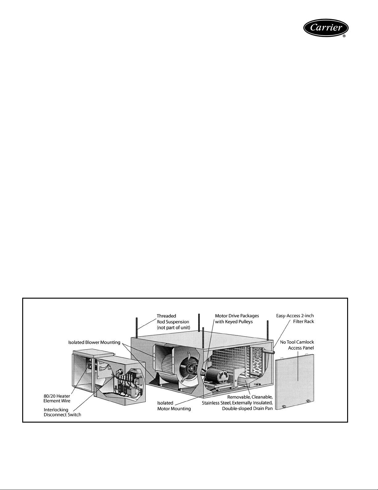
Motor drive packages are provided
with keyed pulleys.
Complete factory assembly
minimizes on-the-jobsite costs
and problems
Compact, lightweight units are designed
for easy mounting. Knockouts designed
to accept
3
/8-in. threaded rods are
provided on the top and bottom of each
corner of the unit One-in. duct collars
on discharge and on return are furnished standard. These integral duct
collars cut installation time and labor
expense.
Durable construction means
easy-to-maintain units
The 42BHC,BVC fan coils casings are
fabricated from heavy-gage galvanized
G90 steel, reinforced for maximum
rigidity and structural strength. Removable side panels with tool-less camlock
fasteners allow easy access for servicing interior components.
One-inch matte surface, fiberglass
thermal/acoustical insulation lines the
fan coil cabinets to prevent sweating
and to muffle sound transmission.
The stainless steel, double-sloped
condensate drain pan extends under
full coil surface to cut maintenance
costs.
Slide-in return-duct collar filter
makes it possible to remove and
replace the filter without disturbing
return air ductwork.
Table of contents
Page
Features/Benefits. . . . . . . . . . . . . . . . . . . . . . . . . . . . . . . . . . . . . . . . . . . 1,2
Model Number Nomenclature . . . . . . . . . . . . . . . . . . . . . . . . . . . . . . . . . . . 3
Physical Data. . . . . . . . . . . . . . . . . . . . . . . . . . . . . . . . . . . . . . . . . . . . . . . 3
Options and Accessories. . . . . . . . . . . . . . . . . . . . . . . . . . . . . . . . . . . . . . 4,5
Base Unit Dimensions . . . . . . . . . . . . . . . . . . . . . . . . . . . . . . . . . . . . . . 6-13
Accessory Dimensions . . . . . . . . . . . . . . . . . . . . . . . . . . . . . . . . . . . . . 14-18
Application Data . . . . . . . . . . . . . . . . . . . . . . . . . . . . . . . . . . . . . . . . . 19-21
Selection Procedure . . . . . . . . . . . . . . . . . . . . . . . . . . . . . . . . . . . . . . . . . 22
Performance Data . . . . . . . . . . . . . . . . . . . . . . . . . . . . . . . . . . . . . . . 23-33
Typical Wiring Schematics . . . . . . . . . . . . . . . . . . . . . . . . . . . . . . . . . .34-36
Electrical Data . . . . . . . . . . . . . . . . . . . . . . . . . . . . . . . . . . . . . . . . . . . . . 37
Controls . . . . . . . . . . . . . . . . . . . . . . . . . . . . . . . . . . . . . . . . . . . . . . . . . 38
Guide Specifications. . . . . . . . . . . . . . . . . . . . . . . . . . . . . . . . . . . . . . . 39,40
INTERNAL FEATURES OF A 42BHC FAN COIL UNIT
2
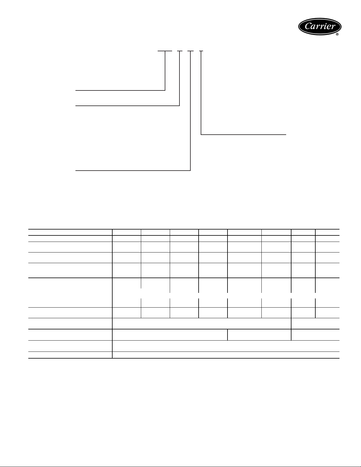
Model number nomenclature
42BH C 08 L
42BH — Vertical Belt Drive Fan Coil Unit
42BV — Vertical Belt Drive Fan Coil Unit
C — Design
Coil —
Rows
B — 4, 2-Pipe
6, 2-Pipe
L —
H — 4/1, Same End Conn.
K — 4/2, Same End Conn.
N — 6/1, Same End Conn.
Q — 6/2, Same End Conn.
R — 8, 2-Pipe
1 — 4 With Electric Heat
Size — Nominal
—
06
600
—
08
800
—
1000
10
12 — 1200
Cfm
2 — 6 With Electric Heat
3 — 8 With Electric Heat
16 — 1600
20 — 2000
30 — 3000
40 — 4000
NOTE: Refer to current 42 Series Master Prices for
complete model definition, including motor, cfm and
total static pressure.
Physical data
UNIT SIZE 42BHC, BVC 06 08 10 12 16 20 30 40
NOMINAL CFM 600 800 1000 1200 1600 2000 3000 4000
42BHC SHIPPING WT (lb)
(no heat/ with heat)
42BVC SHIPPING WT (lb)
(no heat/ with heat)
FILTERS (2 in. pleated)
Number...Size (in.) 1...16
Face Area (sq ft) 2.8 2.8 4.2 4.2 5.5 6.3 8.9 11.7
COILS
Size (in.) 15 x 20 15 x 20 15 x 29 15 x 29 15 x 39 18 x 40 27 x 40 27 x 54
Face Area (sq ft) 2.1 2.1 3.0 3.0 4.1 4.9 7.7 10.3
Fins per inch
Coil Water Weight (approx. lb per
row of coil)
FANS
Number...Size (in.) 1...9 x 4 1...9 x 6 1...10 x 4 1...10 x 7 1...11 x 10 1...12 x 9 1...12 x 12 1...15 x 12
COPPER COIL CONN. 8 ROW
(in.) (Cooling)
COPPER COIL CONN. 4 AND 6 ROW
(in.) (Cooling)
COPPER COIL CONN. 1 AND 2 ROW
(in.) (Heating)
DRAIN CONN. SIZES (in.)
203/234 205/236 253/287 256/290 312/346 344/380 437/474 553/590
200/231 202/233 243/277 247/281 289/323 351/387 436/473 522/559
1
/2x 24 1...161/2x 24 1...181/4x 33 1...181/4x 33 2...181/4x211/22...203/4x 22 2...29 x 22 2...29 x 29
10
0.240 0.240 0.324 0.324 0.420 0.492 0.768 1.020
1OD 1
3
/4OD 1 OD 11/2OD
1
/2OD
3
/4MPT
1
/2OD
3

Options and accessories
42BHC, BVC OPTIONS AND ACCESSORIES
ITEM OPTION* ACCESSORY†
Automatic Air Vents X
Controls X
Electric Heat X
Filters X
Heating/Cooling Coils X
Insulation X
Mixing Boxes X
Motors X
Thermostats X
Valve Packages X
*Factory-installed option.
†Field-installed accessory.
The 42BHC and 42BVC fan coil units are designed to
offer maximum flexibility in an application, accessibility for
service, quiet operation and durability.
Factory-installed options
Automatic air vents — Automatic air vents have fiber-
washers, which allow air in the pipes to pass through,
automatically bleeding the system. The fiber washers eliminate the need to manually remove air from the system.
When wet, washers swell and seal the system.
Coils — Coils are available in a choice of two-pipe system
with 4-row cooling/heating or four-pipe system with 4, 6
or 8-row cooling and 1 or 2 row heating.
Reheat operation is standard. Preheat is available as an
option.
Controls
• Interlocking disconnect switch
• Heater power fusing
• 24 v Class 2 transformer (40 va)
• 8-pole control terminal strip
• Auto reset temperature limit switch
• Airflow safety switch
• Motor power fusing
• Motor control contactor
• 24 v condensate overflow switch
Electric heat — Total electric heat eliminates the require-
ment for a boiler. Heating and/or cooling may be available
on an individual basis throughout the year. Resistance
electric heat is available from 1.0 kW to 40.0 kW (refer to
electric heater data table for availability per unit) with
single-stage or multiple-stage, single power source.
Voltages:
• 115 v, 208 v, 230 v and 277 v single-phase 60 Hz
• 208 v, 230 v and 480 v three-phase 60 Hz
Electric heat is available with the following staging options
(3-phase staging is balanced).
• 1 to 12 kW 1 stage only — single phase
• 3 to 12 kW 1 or 2 stage only — single phase
• 1 to 40 kW 1 stage only — 3 phase
• 4 to 40 kW 1 or 2 stage only — 3 phase
• 12 to 40 kW 1, 2, or 3 stage — 3 phase
Heater coils are constructed of high-grade resistance
wire that is supported by ceramic insulators on plated steel
brackets. These heat elements are suspended directly in
front of the outlet after the blower and the coil. High limit
thermal cutouts protect the heater in the event of air
failure.
Filters — Two in. pleated filters are standard. One-in.
pleated, two 1-in. throwaway, or 2-in. MERV (minimum
efficiency reporting value) 11 filters with 2-in. pleated
pre-filter are available. The 2-in. MERV 11 filters with 2-in.
pleated pre-filter include a filter rack.
Insulation — Tuf-Skin™ II (1-in. thick) insulation is
standard. Units are available with ¾-in. closed cell, 1-in.
Tuf-Skin Rx™ edge sealed, or 1-in. foil-faced insulation.
Motors — A wide selection of standard motors provides
efficient operation in ducted applications with excellent
performance with up to 2 inches of total static pressure.
Available motor options:
• 115 v, 208 v, 230 v and 277 v single-phase 60 Hz
• 208 v, 230 v and 460 v three-phase 60 Hz
• Open drip-proof motors
• External junction box
Field-installed accessories
Mixing boxes — Mixing boxes can be used when outside
air is required for ventilation. Preassembled at the factory
and shipped separately with base rails for field installation,
mixing boxes include a linkage kit consisting of two crank
arms, 2 swivels and either a 25 in. long (for sizes 06-16) or
a 84 in. long (for sizes 20-40) rod for field installation of an
actuator.
4
Thermostats — Three thermostats are available for field
installation:
Honeywell T834C manual changeover, single-stage heat
thermostat features:
• off-cool-heat system switch
• on-auto fan mode switch
• single-stage electric heat
• outside air signal
Honeywell T8500 digital, automatic/manual changeover,
2-stage heat thermostat features:
• digital display of temperatures and all functions
• off-cool-heat-auto system mode buttons
• single speed fan operation
• on-auto fan mode button
• single or two stage electric heat signal
• outside air signal
• remote temperature sensor available
Sunne T170 single-stage heat, 2-pipe heat/cool auto
changeover thermostat features:
• digital display of ambient temperature and operating
mode
• single fan speed operation, power and operating mode
buttons
• continuous fan operation, cycling water control valve
• 4-pipe ACO/MCO (automatic changeover/manual
changeover) with “on-auto” fan mode button
• one or 2 stage electric heat signal available
• purge cycle and temperature sensor for 2-pipe cold
water/hot water systems
• programmable operating range, dead band, digital display, temperature set-back
THERMOSTAT FUNCTIONS
SYSTEM FUNCTION CHANGEOVER
2Pipe HW-Heat Only ACO — XX
2 Pipe CW-Cool Only ACO — XX
2Pipe
2Pipe
2Pipe
4Pipe
ACO — Automatic Changeover
Aux — Auxiliary
CW — Chilled Water
HW — Hot Water
MCO — Manual Changeover
CW/HW
Heat/Cool
CW/HW
Heat/Cool with
Aux. Electric Heat
CW-Cooling with
To t al Electric Heat
CW/HW
Heat/Cool
LEGEND
MCO ——X
ACO ——X
MCO ——X
ACO ——X
MCO X X X
ACO — XX
MCO X X X
ACO — XX
THERMOSTATS
Honeywell
T834C
Honeywell
T8500
Sunne
T170
Valve packages — Valve packages are factory assembled
for field installation. Motorized valves (24 v) can be operated with power on with spring return or power off/power
on.
It is recommended that basic motor controls are ordered
when valve packages are ordered.
5
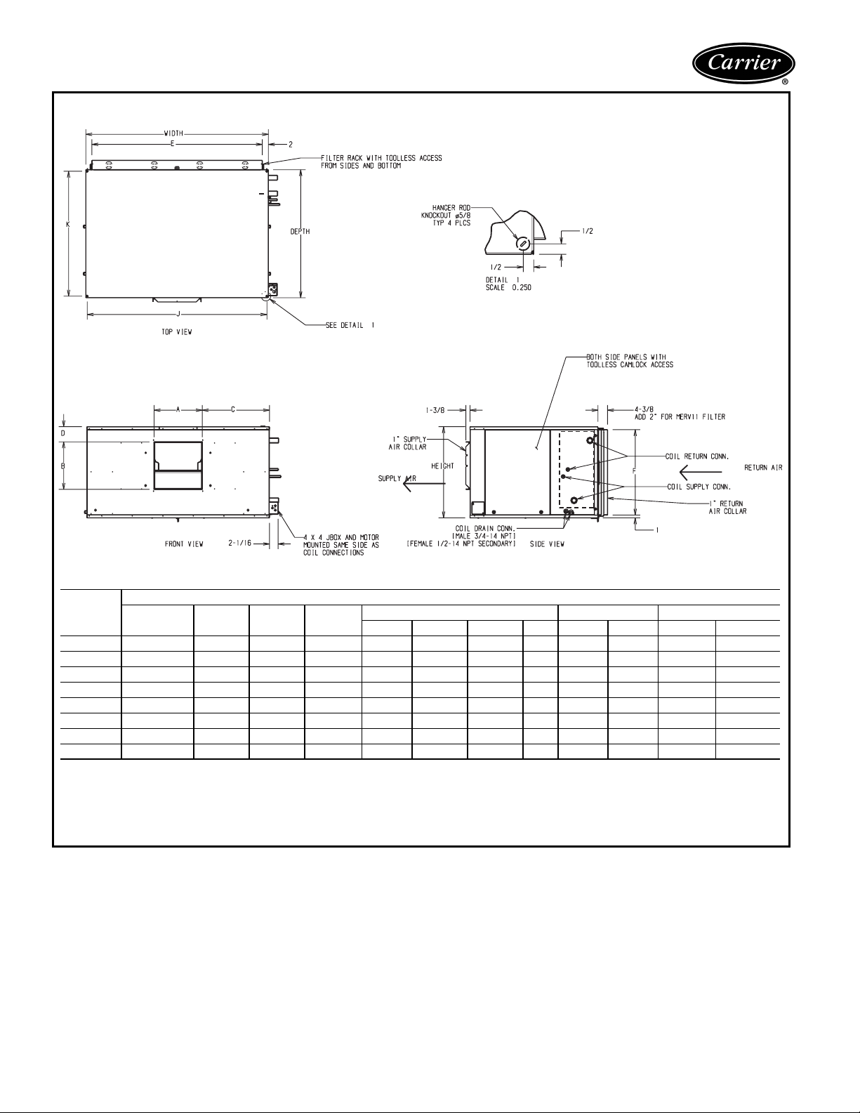
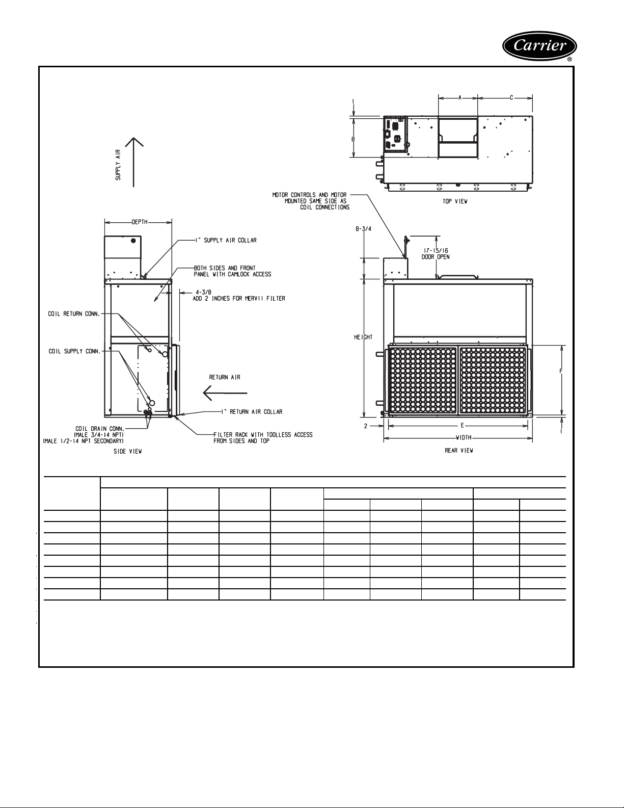
Base unit dimensions
42BHC FAN COIL BASE UNIT (NO CONTROLS)
UNIT
42BHC
06 9x 4 36
08 9x 6 363/
10 10 x 4 373/
12 10 x 7 373/
16 11 x 10 3715/
20 12 x 9 40
30 12 x 12 403/
40 15 x 12 439/
NOTES:
1. All dimensions are in inches (±
2. Any modifications to product specifications by any person are subject to acceptance of the factory. Product specifications are subject to
Fan Size Depth Width Height
3
/
2811/
16
2811/
16
371/
4
371/
4
471/
16
3
/
481/
8
481/
8
621/
16
1
/4in.).
16
16
16
16
16
16
16
16
181/
2
181/
2
201/
4
201/
4
201/
4
223/
4
31 157/
31 167/
DIMENSIONS (in.)
Supply Duct Return Duct Mounting Holes
AB CDEF J K
71/
89/
71/
915/161111/
135/
121/
109/
8
109/
16
1111/
2
1211/
16
133/
2
133/
8
161/
16
137/
16
137/
16
137/
16
137/
16
1613/
16
173/
4
161/
4
2213/
16
8
8
8
8
16
4
16
16
11/8241/
11/8241/
11/8331/
11/8331/
11/8431/
11/8441/
61/8441/
51/8581/
167/
16
167/
16
183/
16
183/
16
183/
16
2011/
16
2815/
16
2815/
16
273/
16
273/
16
363/
16
363/
16
463/
16
473/
16
473/
16
613/
16
351/
16
16
16
16
16
16
16
16
351/
3613/
3613/
37
397/
397/
425/
4
4
16
16
8
change without notice.
3. Right hand shown, left hand opposite.
4. Hanger rods, which are field-supplied, are shown for reference only.
16
16
6
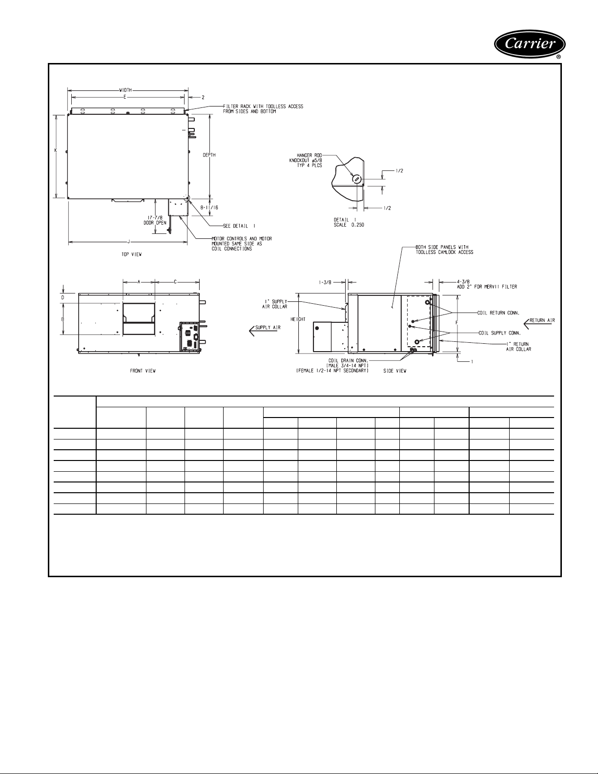
42BHC FAN COIL WITH MOTOR CONTROL OPTION
UNIT
42BHC
06 9x 4 36
08 9x 6 363/
10 10 x 4 373/
12 10 x 7 373/
16 11 x 10 3715/
20 12 x 9 40
30 12 x 12 403/
40 15 x 12 439/
NOTES:
1. All dimensions are in inches (±
2. Any modifications to product specifications by any person are subject to acceptance of the factory. Product specifications are subject to
Fan Size Depth Width Height
3
/
2811/
16
2811/
16
371/
4
371/
4
471/
16
3
/
481/
8
481/
8
621/
16
1
/4in.).
16
16
16
16
16
16
16
16
181/
2
181/
2
201/
4
201/
4
201/
4
223/
4
31 157/
31 167/
DIMENSIONS (in.)
Supply Duct Return Duct Mounting Holes
AB CDEF J K
71/
89/
71/
915/
135/
121/
109/
8
109/
16
1111/
2
1111/
16
1211/
16
133/
2
133/
8
161/
16
137/
16
137/
16
137/
16
137/
16
1613/
16
173/
4
161/
4
2213/
16
8
8
8
8
16
4
16
16
11/8241/
11/8241/
11/8331/
11/8331/
11/8431/
11/8441/
61/8441/
51/8581/
167/
16
167/
16
183/
16
183/
16
183/
16
2011/
16
2815/
16
2815/
16
273/
16
273/
16
363/
16
363/
16
463/
16
473/
16
473/
16
613/
16
351/
16
16
16
16
16
16
16
16
351/
3613/
3613/
37
397/
397/
425/
4
4
16
16
16
16
8
change without notice.
3. Right hand shown, left hand opposite.
4. Hanger rods, which are field-supplied, are shown for reference only.
7
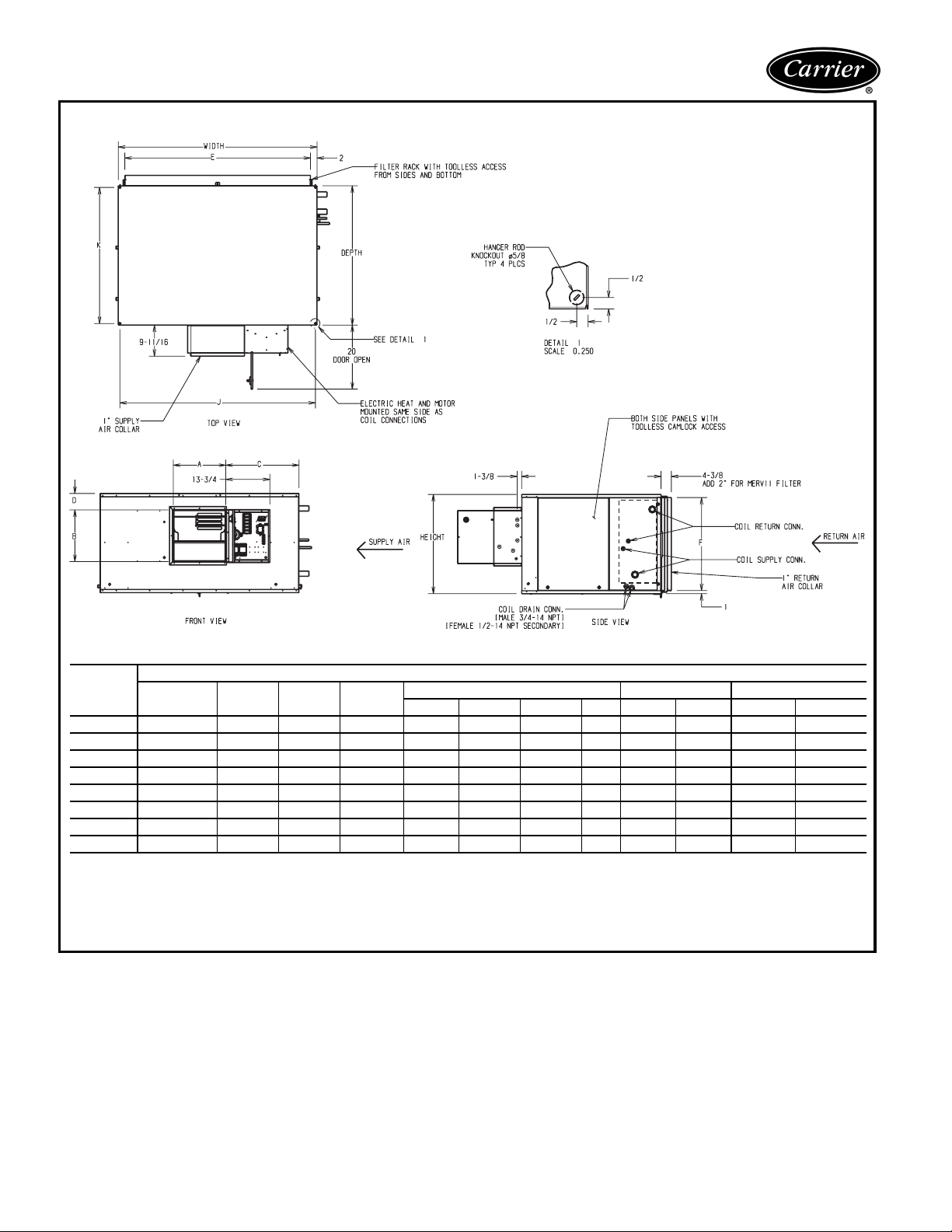
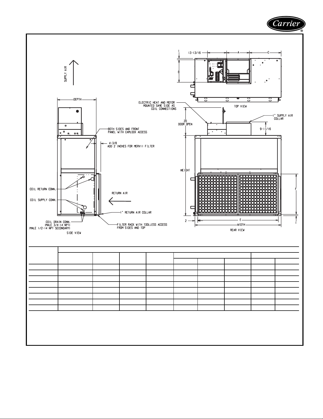
Base unit dimensions (cont)
42BHC FAN COIL WITH ELECTRIC HEAT OPTION
UNIT
42BHC
06 9x 4 36
08 9x 6 363/
10 10 x 4 373/
12 10 x 7 373/
16 11 x 10 3715/
20 12 x 9 40
30 12 x 12 403/
40 15 x 12 439/
NOTES:
1. All dimensions are in inches (±
2. Any modifications to product specifications by any person are subject to acceptance of the factory. Product specifications are subject to
change without notice.
Fan Size Depth Width Height
3
/
2811/
16
2811/
16
371/
4
371/
4
471/
16
3
/
481/
8
481/
8
621/
16
1
/4in.).
16
16
16
16
16
16
16
16
181/
181/
201/
201/
201/
223/
31 157/
31 167/
2
2
4
4
4
4
DIMENSIONS (in.)
Supply Duct Return Duct Mounting Holes
AB CDEF J K
71/
89/
71/
915/
135/
121/
109/
8
109/
16
1111/
2
1111/
16
1211/
16
133/
2
133/
8
161/
16
137/
16
137/
16
137/
16
137/
16
1613/
16
173/
4
161/
4
2213/
16
8
8
8
8
16
4
16
16
11/8241/
11/8241/
11/8331/
11/8331/
11/8431/
11/8441/
61/8441/
51/8581/
167/
16
167/
16
183/
16
183/
16
183/
16
2011/
16
2815/
16
2815/
16
273/
16
273/
16
363/
16
363/
16
463/
16
473/
16
473/
16
613/
16
351/
16
16
16
16
16
16
16
16
351/
3613/
3613/
37
397/
397/
425/
4
4
16
16
8
3. Right hand shown, left hand opposite.
4. Hanger rods, which are field-supplied, are shown for reference only.
16
16
8
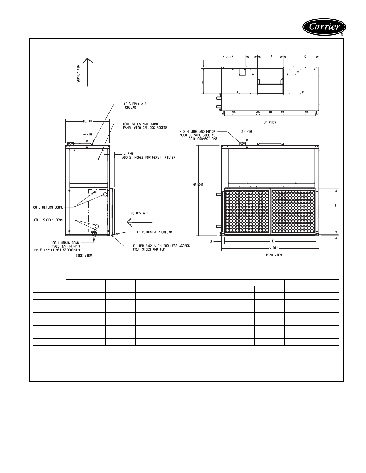
42BVC FAN COIL BASE UNIT (NO CONTROLS)
UNIT
42BVC
06 9x 4 20 28
08 9x 6 20 281/
10 10 x 4 22 371/
12 10 x 7 22 371/
16 11 x 10 22 471/
20 12 x 9 24 481/
30 12 x 12 28 481/
40 15 x 12 28 621/
NOTES:
1. All dimensions are in inches (±
2. Any modifications to product specifications by any person are subject to acceptance of the factory. Product specifications are subject to
change without notice.
Fan Size Depth Width Height
1
/
16
16
16
16
16
16
16
16
1
/4in.).
DIMENSIONS (in.)
361/
2
361/
2
393/
8
393/
8
393/
451/
543/
575/
8
8
16
8
135/
121/
157/
167/
Supply Duct Return Duct
AB CEF
71/
89/
71/
915/
8
16
2
16
16
2
8
16
109/
109/
1111/
1111/
1211/
133/
133/
161/
16
16
16
16
16
4
4
16
33/
33/
51/
51/
167/
1713/
161/
227/
4
4
2
2
8
16
8
8
241/
241/
331/
331/
431/
441/
441/
581/
167/
16
16
16
16
16
16
16
16
167/
183/
183/
183/
2011/
2815/
2815/
16
16
16
16
16
3. Right hand shown, left hand opposite.
4. Hanger rods, which are field-supplied, are shown for reference only.
16
16
16
9
Base unit dimensions (cont)
42BVC FAN COIL WITH MOTOR CONTROL OPTION
UNIT
42BVC
06 9x 4 20 28
08 9x 6 20 281/
10 10 x 4 22 371/
12 10 x 7 22 371/
16 11 x 10 22 471/
20 12 x 9 24 481/
30 12 x 12 28 481/
40 15 x 12 28 621/
NOTES:
1. All dimensions are in inches (±
2. Any modifications to product specifications by any person are subject to acceptance of the factory. Product specifications are subject to
NOTES:
change without notice.
1. All dimensions are in inches (±
3. Right hand shown, left hand opposite.
2. Any modifications to product specifications by any person are
4. Hanger rods, which are field-supplied, are shown for reference only.
subject to acceptance of the factory. Product specifications are
subject to change without notice.
3. RH shown, LH opposite.
Fan Size Depth Width Height
1
/
16
16
16
16
16
16
16
16
1
/4in.).
1
/4in.).
DIMENSIONS (in.)
361/
2
361/
2
393/
8
393/
8
393/
451/
543/
575/
8
8
16
8
135/
121/
157/
167/
Supply Duct Return Duct
AB CEF
71/
89/
71/
915/
8
16
2
16
16
2
8
16
109/
109/
1111/
1111/
1211/
133/
133/
161/
16
16
16
16
16
4
4
16
33/
33/
51/
51/
167/
1713/
161/
227/
4
4
2
2
8
8
8
241/
16
241/
16
331/
16
331/
16
431/
16
441/
16
441/
581/
16
16
16
4. Hanger rods, which are field-supplied, are shown for reference
only.
167/
167/
183/
183/
183/
2011/
2815/
2815/
16
16
16
16
16
16
16
16
10
42BVC FAN COIL WITH ELECTRIC HEAT OPTION
UNIT
42BVC
06 9x 4 20 28
08 9x 6 20 281/
10 10 x 4 22 371/
12 10 x 7 22 371/
16 11 x 10 22 471/
20 12 x 9 24 481/
30 12 x 12 28 481/
40 15 x 12 28 621/
NOTES:
1. All dimensions are in inches (±
2. Any modifications to product specifications by any person are subject to acceptance of the factory. Product specifications are subject to
Fan Size Depth Width Height
1
/
16
16
16
16
16
16
16
16
1
/4in.).
DIMENSIONS (in.)
361/
2
361/
2
393/
8
393/
8
393/
451/
543/
575/
8
8
16
8
135/
121/
157/
167/
Supply Duct Return Duct
AB CEF
71/
89/
71/
915/
8
16
2
16
16
2
8
16
109/
109/
1111/
1111/
1211/
133/
133/
161/
16
16
16
16
16
4
4
16
33/
33/
51/
51/
167/
1713/
161/
227/
4
4
2
2
8
16
8
8
241/
241/
331/
331/
431/
441/
441/
581/
16
16
16
16
16
16
16
16
167/
167/
183/
183/
183/
2011/
2815/
2815/
change without notice.
3. Right hand shown, left hand opposite.
4. Hanger rods, which are field-supplied, are shown for reference only.
16
16
16
16
16
16
16
16
11
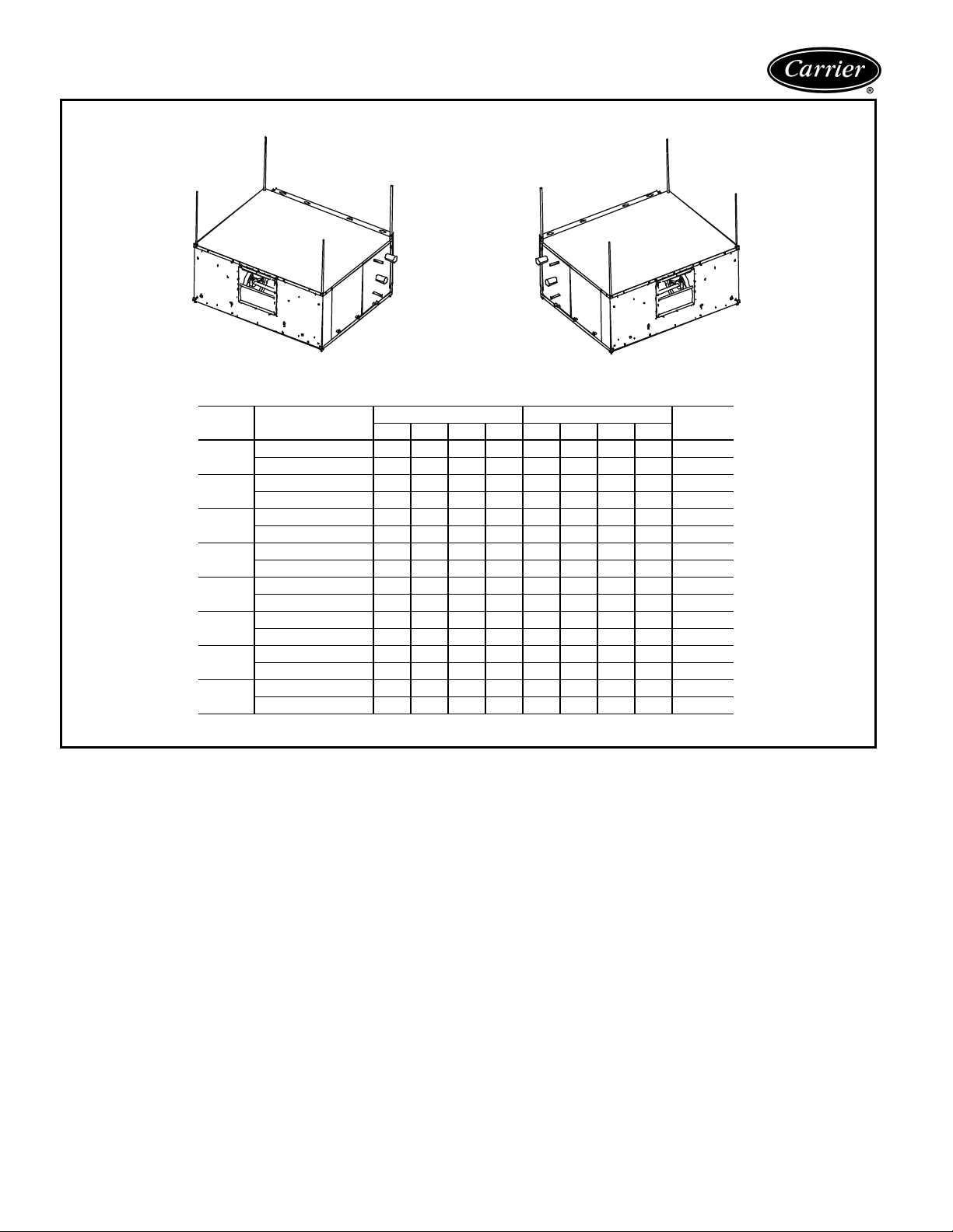
Base unit dimensions (cont)
42BHC UNIT CORNER WEIGHTS (lb)
1
3
4
RIGHT HAND UNIT
UNIT
42BHC
NOTE: Unit weights (shown in pounds) ±10%, are based on the 8-row coil and 1 Hp motor.
CONFIGURATION
06
08
10
12
16
20
30
40
No Heat 50 55 47 51 55 50 51 47 203
With Heat 50 58 59 67 58 50 67 59 234
No Heat 51 55 47 52 55 51 52 47 205
With Heat 50 59 59 68 59 50 68 59 236
No Heat 63 71 55 63 71 63 63 55 253
With Heat 62 76 68 81 76 62 81 68 287
No Heat 64 72 56 64 72 64 64 56 256
With Heat 63 76 68 82 76 63 82 68 290
No Heat 80 87 69 76 87 80 76 69 312
With Heat 79 91 82 95 91 79 95 82 346
No Heat 90 98 74 82 98 90 82 74 344
With Heat 90 102 88 100 102 90 100 88 380
No Heat 118 127 92 100 127 118 100 92 437
With Heat 118 131 106 119 131 118 119 106 474
No Heat 155 162 114 122 162 155 122 114 553
With Heat 155 166 129 140 166 155 140 129 590
2
RIGHT-HAND UNITS LEFT-HAND UNITS
12341234
1
3
LEFT HAND UNIT
2
4
TOTAL
WEIGHT
12

42BVC UNIT CORNER WEIGHTS (lb)
1
3
2
4
1
3
1
3
2
4
RIGHT HAND UNIT
UNIT
42BVC
06
08
10
12
16
20
30
40
NOTE: Unit weights (shown in pounds) ±10% are based on the 8-row coil and 1 Hpmotor.
CONFIGURATION
No Heat 52 54 51 43 54 52 43 51 200
With Heat 58 65 61 47 65 58 47 61 231
No Heat 53 55 51 43 55 53 43 51 202
With Heat 58 66 62 47 66 58 47 62 233
No Heat 63 69 61 50 69 63 50 31 243
With Heat 69 81 72 54 81 69 54 72 277
No Heat 64 70 62 51 70 64 51 62 247
With Heat 70 82 73 55 82 70 55 73 281
No Heat 74 85 72 58 85 74 58 72 289
With Heat 80 98 84 61 98 80 61 84 323
No Heat 90 108 86 68 108 90 68 86 351
With Heat 95 123 99 71 123 95 71 99 387
No Heat 110 139 106 81 139 110 81 106 436
With Heat 115 155 120 83 155 115 83 120 473
No Heat 131 172 125 94 172 131 94 125 522
With Heat 135 190 140 95 190 135 94 140 559
RIGHT-HAND UNITS LEFT-HAND UNITS
12341234
1
3
LEFT HAND UNIT
2
2
WEIGHT
4
4
TOTAL
TOTAL WEIGHT UNIT CORRECTION FACTOR (lb)
Corner weights on pages 12 and 13 are for 8-row water filled coils. For a different number of rows, total unit weight
can be determined by the following procedure:
• Identify the number of rows and the size of the unit.
• Determine the total weight of the unit from the Corner Weight tables.
• From the table below, identify the correction factor (for size of unit and number of rows) and subtract this from the
total weight.
UNITS
42BHC,BVC
06 21 16 11 5
08 21 16 11 5
10 28 21 14 7
12 28 21 14 7
16 39 29 20 10
20 46 35 23 12
30 74 55 37 18
40 98 74 49 25
4ROWS 5ROWS 6ROWS 7ROWS
Correction Factors (lb)
13

Accessory dimensions
MIXING BOX
1
2.4
A
C
BOTTOM/REAR INLET
WB
2
B
2
W
TOP VIEWS
A
3
A
H
2.4
4
2.4
1
4
2.4
H
A
3
C
TOP/REAR INLET
14
NOTE: All dimensions in inches.
RIGHT HAND SIDE VIEWS
42BHC,BVC
UNIT SIZE
06 18.5 28 6 24 11
08 18.5 28 6 24 11
10 20.25 37 8 33 13
12 20.25 37 8 33 13
16 20.25 47 8 43 13
20 22.75 48 8 44 13
30 31.0 481044 15
40 31.0 481044 15
DIMENSIONS (in.)
HWABC

MIXING BOX RAILS
W
FRONT VIEW
NOTE: All dimensions in inches.
UNIT
42BHC06 28 51.6 16.1
42BHC08 28 51.6 16.1
42BHC10 37 55.2 18.1
42BHC12 37 55.2 18.1
42BHC16 47 55.4 18.1
42BHC20 48 57.8 18.1
42BHC30 48 59.8 20.1
42BHC40 62 63.0 20.1
DIMENSIONS (in.)
WD A
1
1
D
A
3
SIDE VIEW
UNIT
42BVC06 28 35.5 16.1
42BVC08 28 35.5 16.1
42BVC10 37 39.5 18.1
42BVC12 37 39.5 18.1
42BVC16 47 39.5 18.1
42BVC20 48 41.5 18.1
42BVC30 48 47.5 20.1
42BVC40 62 47.5 20.1
DIMENSIONS (in.)
WD A
15

Accessory dimensions (cont)
VALVE PACKAGES
Basic — Basic valve package includes 2 or 3-way
valves with balancing valves and 2 ball valvs.
B
A
D
Deluxe — Deluxe valve package includes a circuit
setter and a strainer in addition to the components
listed under basic valve package.
F
E
D
A
B
NOTE: All dimensions in inches.
CONTROL VALVE
Normal Close Off
Spring Return
High Close Off
Power On/
Power Off
PIPING
PACKAGE
2-way
3-way
2-way
3-way
C
E
F
SIZEABCDE FCv
1
/2in. 12.45 2.285 — — 15.25 7.41 3.5 25 psig
3
/4in. 12.71 3.156 — — 17.71 7.936 5 20 psig
1 in. 14.88 3.38 — — 20.81 9.6 8 17 psig
1
/2in. 12.99 14.7 1.823 5.805 16.29 19.32 4 25 psig
3
/4in. 12.84 16.24 2.318 7.411 17.34 21.02 5 20 psig
1 in. 14.72 19.38 2.774 8.247 20.65 25.19 8 17 psig
1
/2in. 13.29 2.285 — — 16.09 7.41 3.5 60 psig
3
/4in. 13.59 3.156 — — 18.59 7.936 4.6 60 psig
1 in. 14.97 3.38 — — 20.90 9.6 6.6 60 psig
1
/2in. 13.41 15.54 2.031 6.014 16.71 20.16 3.8 60 psig
3
/4in. 13.03 16.62 2.219 7.313 17.53 21.4 5.9 60 psig
1 in. 14.77 19.47 2.731 8.248 20.70 25.28 9 60 psig
CLOSE
C
OFF
16

PIPING CONNECTION LOCATION DIAGRAM*
HWS
HWR
D
C
B
A
2(51)
1-5/8(41)
RH Tell-Tale
CWR
CWS
Drain
0
)462(8/3-01
E
)912(8/5-8
F
)571( 8/7-6
G
H
0
LH Tell-Tale
LEGEND
CWR — Cold Water Return
CWS — Cold Water Supply
HWR — Hot Water Return
HWS — Hot Water Supply
LH — Left Hand
RH — Right Hand
SO — Stub Out
*Right-hand unit with re-heat coil shown.
42BHC,BVC
UNIT SIZE
06 1 0.75 0.75 0.5
08 1 0.75 0.75 0.5
10 1 0.75 0.75 0.5
12 1 0.75 0.75 0.5
16 11 1 0.5
20 11 1 0.5
30 1.5 1.5 1.5 0.5
40 1.5 1.5 1.5 0.5
8RowCoilSO
Nominal
Use the table on the next page to determine the location of the piping
connections. For example, on a size 20 unit with 4 rows and a right
hand connection, the location of the chilled water supply line is determined by G (6 in.) and B (7
HEAD STUB OUT SIZES (in.)
6RowCoilSO
Nominal
4RowCoilSO
Nominal
4
/5in.).
Heating 1 or 2 SO
Row Coil Nominal
17

Accessory dimensions (cont)
HEAT OPTIONS
Re-heat
Pre-heat*
*Factory-installed option.
42BHC,BVC
UNIT SIZE
06/08
10/12
16
20
30/40
06/08
10/12
16
20
30/40
COIL ROWS DIMENSIONS (in.)
0—
4
13
23
0— ———
6
13
23
80 — — ——10
4
0—
15
25
6
0— ———
15
25
80 — — ——10
4
0—
1
25
0— ———
6
1
25
80 — — ——10
4
0—
1
25
0— ———
6
1
25
80 — — ——10
4
0—
1
23
0— ———
6
1
23
80 — — ——10
4
6
80 — 6
0—6
13
23
0—6
13
23
0—7
4
15
25
0—7
6
15
25
80 — 7
4
0—7
15
25
6
0—7
15
25
80 — 7
4
6
80 — 7
0—7
15
25
0—7
15
25
0—5
4
13
23
0—5
6
13
23
80 — 5
A BCDEFGHCool Heat
1
/
13
/
1
/
13
/
1
/
7
/
16
1
/
27
/
LH 105/
RH 133/
7
/
16
LH 105/
RH 133/
7
/
16
LH 1115/
RH 1411/
1
/
LH 1115/
RH 1411/
1
/
LH 141/
RH 1813/
5
/
LH 141/
RH 1813/
5
/
1
/
13
/
1
/
13
/
1
/
7
/
16
1
/
7
/
16
1
/
7
/
16
1
/
7
/
16
3
/
16
1
/
3
/
16
1
/
5
/
16
5
/
5
/
16
5
/
———
2
16
2
16
8
8
61
61/
8
73/
4
123/
143/
4
8
151/
2
1513/
16
151/
2
1513/
16
———
171/
8
177/
16
171/
8
177/
16
77
79/
16
93/
16
93/
4
77
79/
16
93/
16
93/
4
———
8
8
73/
8
8
4
155/
8
177/
177/
12
16
12
16
95/
95/
79/
1113/
1113/
93/
8
8
16
16
16
4
———
16
16
2
16
16
2
713/
16
183/
16
135/
201/
135/
201/
16
16
16
16
95/
95/
79/
1113/
1113/
93/
8
8
16
16
16
4
———
16
16
8
16
16
8
2
16
2
16
8
8
8
8
2
2
8
8
515/
87/
713/
87/
713/
69/
515/
69/
515/
16
1
/
8
63/
4
61/
8
1
/
8
63/
4
61/
8
1
/
8
3
/
4
83/
8
73/
4
3
/
4
83/
8
73/
4
3
/
4
3
/
4
83/
8
73/
4
3
/
4
83/
8
73/
4
3
/
4
13
/
16
16
16
13
/
16
16
16
13
/
16
15
/
16
16
16
15
/
16
16
16
15
/
16
265/
16
123/
4
133/
8
123/
4
123/
4
133/
8
123/
4
123/
4
143/
8
15 171/
143/
8
143/
8
15 171/
143/
8
143/
8
155/
8
161/
4
155/
8
155/
8
161/
4
155/
8
155/
8
183/
16
1813/
16
183/
16
183/
16
1813/
16
183/
16
183/
16
265/
16
2615/
16
265/
16
265/
16
2615/
16
265/
16
265/
16
167/
16
281/
8
167/
16
281/
8
———5
151/
2
1513/
16
———8
151/
2
1513/
16
———10
———5
8
177/
16
———8
8
177/
16
———10
———5
171/
8
177/
16
———8
171/
8
177/
16
———10
———5
193/
4
201/
16
———8
193/
4
201/
16
———10
———5
2713/
16
281/
8
—3
2713/
16
281/
8
—3
95/
8
95/
8
79/
16
1113/
16
1113/
16
93/
4
211/
16
31/
4
211/
16
31/
4
211/
16
31/
4
211/
16
31/
4
211/
16
31/
4
211/
16
31/
4
211/
16
31/
4
211/
16
31/
4
——73
211/
16
1
/
4
——9
211/
16
1
/
4
515/
79/
93/
79/
93/
79/
93/
93/
79/
93/
93/
79/
103/
103/
211/
93/
93/
7
7
93/
7
7
93/
8
8
93/
31/
16
16
81/
8
16
4
1
/
4
515/
16
16
81/
8
16
4
1
/
4
515/
16
16
16
81/
8
1
/
4
515/
16
81/
8
1
/
4
515/
16
81/
8
1
/
4
15
/16211/
733/
81/847/
1
/8211/
211/
16
4
16
16
16
4
16
16
16
4
16
4
211/1693/1633/
31/4101/447/
211/
31/
211/1693/1633/
31/4101/447/
211/
31/
211/1693/1633/
31/4101/447/
211/
31/
1
/4211/
15
/16211/
733/
16
81/847/
4
1
/8211/
1
/4211/
15
/16211/
733/
16
81/847/
4
1
/8211/
1
/4211/
15
/16211/
733/
16
81/847/
4
1
/8211/
211/1693/1633/
31/4101/447/
211/
31/
211/16101/447/
1
/4211/
15
/16211/
81/847/
16
81/8211/
4
3
/1633/
31/4101/4211/
16
16
4
8
16
4
8
16
16
4
8
16
4
8
16
16
4
8
16
4
8
16
16
4
8
16
4
8
16
16
3
/
4
8
16
4
8
16
18

Application data
Basic definitions
Unit hand — When facing the supply air outlet from the
front of the unit (air blowing in your face), your right hand
will be the right hand side of the unit and your left hand the
left hand side of the unit.
PIPING COMPONENTS
SYMBOL/SKETCH DESCRIPTION
MANUAL AIR VENT: Threaded brass needle valve
with screwdriver slot for adjustment.
Application — Body brazed into high point of heat-
ing and cooling coils for bleeding air from coil. Standard item on all hydronic coils (not used on steam
or DX coils). Should not be used in lieu of main system air vents.
AUTOMATIC AIR VENT: Nickel plated brass valve,
fiber-disc type, with positive shut-off ballcheck and
quick vent feature via knurled vent screw.
Application — Optional replacement for manual air
vent. Automatically passes minute quantities of air
through the fiber discs which expand upon contact
with water, completely sealing the valve. As air
accumulates, the fiber discs dry and shrink, repeating the cycle. Not recommended for removing large
quantities of air encountered during initial start-up
or subsequent draining and refilling. Should not be
used in lieu of main system air vents.
SWAGE: Copper tube end expanded to accept a
copper tube of the same size for factory or field
brazing.
Application — Used where possible for all tubing
joints for best joint integrity.
CIRCUIT SETTER: Variable water flow balancing
valve with manual adjustment knob, pointer, percent-open scale, memory stop and integral pressure read-out ports.
Application — Used for close tolerance water flow
balancing. Positive shut-off ball valve feature allows
usage as combination balancing and shut-off valve.
LEGEND
Cv — Coefficient of Velocity
DX— Direct Expansion
*Check all system component pressure ratings (coils, values, pumps,
etc.) with manufacturer and any applicable local or national piping
codes prior to specifying system pressure rating.
UNIT HAND
CVFACTOR RATING*
1
/
2
N/A N/A 400 100
N/A N/A 125 240
N/A N/A 300 200
2.12 3.9 300 250
3
/
4
PSI F
19

Application data (cont)
PIPING COMPONENTS (cont)
SYMBOL/SKETCH DESCRIPTION
BALANCE VALVE: Variable water flow manual bal-
ancing valve with screwdriver slot adjustment
screw.
Application — Often used in conjunctionwithtest
port fittings for water flow balancing. Balance by
temperature differential or coil pressure drop
(check specifications for service fittings required if
balancing by pressure drop). May be used in 3-way
valve bypass line to permit equal flow balancing.
STRAINER: Y-type body with 50 mesh stainless
steel screen.
Application — Used for removal of small particles
from system water during normal system operation.
Should not be used in lieu of main system strainers. Strainer screen may have to be removed during initial high pressure system flushing during
start-up. Screen should be removed and cleaned
per normal maintenance schedule (provisions for
strainer blow-down not provided).
BALL VALVE: Manual balance and shut-off valve.
Application — Used for unit isolation and water flow
balancing. Without memory stop feature water balance point must be marked by installer (if necessary). Check specifications for service fittings
required when used for water balancing.
LEGEND
Cv — Coefficient of Velocity
DX— Direct Expansion
*Check all system component pressure ratings (coils, values, pumps,
etc.) with manufacturer and any applicable local or national piping
codes prior to specifying system pressure rating.
CVFACTOR RATING*
1
/
2
3
/
4
PSI F
3.0 8.9 150 200
9.0
Clean
19.0
Clean
400 250
4.0 7.5 400 200
20

PIPING COMPONENTS (cont)
SYMBOL/SKETCH DESCRIPTION
2-WAY MOTORIZED VALVE: Electric
2-position flow control valve (open/closed).
Normally closed body with manual override
lever. Installed in supply line to unit.
Application — All standard control and valve
packages are based upon normally closed
valves (valve electrically powered open and
closed by spring return when electric power
removed). Manual override lever allows valve
to be placed in the open position for secondary (unit) flushing, constant water flow prior to
start-up, etc. Manual override is automatically
disengaged when valve is electrically activated. Consult factory for normally open
valve applications.
3-WAY MOTORIZED VALVE: Electric
2-position flow control valve (closed to coil/
open to bypass or open to coil/closed to
bypass). Normally closed with manual override lever. Installed in supply line to unit.
Application — Same comments as 2-way
motorized valve except with manual override
lever engaged the valve is open to both ports
and water flow will take the path of least resistance through the valve package (not necessarily 100% through the coil).
C
FACTO R
V
1
/
2
3
/
4
1 PSI F
3.5 5.0 8.0
SPRING RETURN
3.5 4.6 6.6
POWER ON/OFF
4.0 5.0 8.0
SPRING RETURN
3.8 5.9 9.0
RATING
300 200
300 200
LEGEND
Cv — Coefficient of Velocity
DX— Direct Expansion
NOTES:
1. Motorized spring return 2-way valves have a maximum close-off differential of 25 psi.
2. Motorized spring return 3-way valves have a maximum close-off differential of 25 psi.
POWER ON/OFF
21

Selection procedure
This selection procedure provides a guide to determine
unit performance of the 42BHC, BVC units. Capacity
tables (in Performance Data) are based on nominal cfm.
Correction factors are provided for other operating conditions as explained in the following selection example.
For applications outside the range provided in this
catalog, please consult the factory.
FORMULAS:
TC = TCb x Ct x Et
SC = SCb x Cs x Es
Where:
Cs = Sensible Airflow Correction Factor
Ct = Total Airflow Correction Factor
Es = Sensible Elevation Correction Factor
Et = Total Elevation Correction Factor
SC = Sensible Capacity
SCb = Base Sensible Capacity from Base Cooling Capaci-
ties by gpm charts
TC = Total Capacity
TCb = Base Total Capacity from Base Cooling Capacities
by gpm charts
EXAMPLE:
I Rate unit performance.
To rate the performance at sea level for a 42BHC16
unit with a four-row coil at 80 F/67 F EAT, 45 F EWT,
7 gpm water flow, and 1500 cfm:
a) Enter the Base Cooling Capacities by Gpm, 4-Row
Capacity Units table at 80 F/67 F EAT and
45 F EWT.
b) Locate the appropriate row for unit size 16 and
7 gpm.
Record the tabulated base performance.
TCb = 42.0 MBtuh
SCb = 34.2 MBtuh
∆T = 12.0 F
c) Divide CFM Actual by CFM Nominal to determine
Cfm Ratio.
Cfm Ratio = 1500/1600 =.9375
II Select CFM correction factors.
Select the Cfm correction factors, Ct and Cs, from the
Airflow Correction Factors table. (Interpolation may be
required.)
Ct = .9625
Cs = .96
Select the elevation correction factors, Et and Es, from
the Elevation Correction Factors table. (No correction
necessary in this example, unit is at sea level.)
Et = 1.00
Es = 1.00
III Calculate actual performance.
TC = TCb x Ct x Et
= 42.0 x .9625 x 1.00
= 40.42 MBtuh
SC = SCb x Cs x Es
= 34.2 x .96 x 1.00
= 32.83 MBtuh
a) Calculate water pressure drop (or refer to the Water
Pressure Drop for Cv Factor and Water Flow Rate
table on page 33). From the Cv Factor by Coil and
Unit Size table on page 32, find the Cv value for
unit size 16 with four rows.
Cv = 7.2
P = [GPM/(0.658 x Cv)]2
= [7.0/(0.658 x 7.2)]2
= 2.18 feet of H
b) For selections other than those listed here, please
contact the factory.
IV Determine motor.
To determine motor and drive selection requirements
and obtain the cfm for a specific application, the
total static pressure (TSP) for that application must be
determined.
The TSP is the sum of the internal static pressure
(ISP) and the external static pressure (ESP) measured in
inches of water column. Internal static pressure is the
sum of the static resistance of the unit’s components
— the cabinet, coil and filter. The ESP is the static
resistance of the unit’s external components, including,
but not limited to, ductwork, grilles and additional
filtration. For non-ducted applications, the ESP is
0 in. wg.
After the TSP has been calculated (see the following
example), use the motor horsepower table on pages 30
and 31 to determine actual horsepower (hp) for the belt
drive unit. Horsepower offerings are limited to
1
/2, 3/4, 1, 11/2, 2, 3 and 5.
The standard selection is the nearest offering above
the actual hp shown in the table.
Using the TSP of the table, match the unit size with
the cfm row to determine the correct motor for the
specific application. Drive sheaves and the required
belt assembly will be provided to meet specific design
requirements. Drive sheaves are set at the factory.
Calculate the hp and drive selection required to deliver 1500 cfm on a 42BHC16 unit equipped with a
4-row hydronic cooling coil and a 2-in. pleated filter in
a ducted application at .38 in. ESP, including duct and
grille losses.
Using the Component Static Resistance table on
page 32, the ISP is calculated as follows:
Cabinet .09-in. wg
4-row Wet Coil .30-in. wg
2-in. Pleated Filter .12-in. wg
ISP .51-in. wg
ESP .38-in. wg
TSP .89-in. wg
O
2
1
/4, 1/3,
22

Performance data
42BHC,BVC AIRFLOW CORRECTION FACTORS
CFM RATIO
(Actual/Base)
1.40 1.25 1.26
1.35 1.22 1.23
1.30 1.19 1.20
1.25 1.16 1.17
1.20 1.13 1.14
1.15 1.10 1.11
1.10 1.07 1.08
1.05 1.04 1.04
1.00 1.00 1.00
0.95 0.97 0.97
0.90 0.94 0.93
0.85 0.90 0.89
0.80 0.86 0.85
0.75 0.82 0.81
0.70 0.78 0.77
0.65 0.74 0.72
0.60 0.70 0.67
0.55 0.66 0.62
0.50 0.62 0.57
0.45 0.58 0.52
0.40 0.53 0.47
0.35 0.48 0.42
0.30 0.43 0.38
0.25 0.38 0.33
NOTE: Use Sensible Heat correction factors when calculating heating
capacity.
TOTAL (Ct) SENSIBLE (Cs)
DIRECT EXPANSION (DX) CORRECTION FACTORS
%OF
NOMINAL CFM
80 0.95 0.93
90 0.97 0.96
100 1.00 1.00
110 1.02 1.04
120 1.05 1.08
Consult factory for values outside of table.
DX Total Capacity (MBtuh) = Base Et x Total Correction Factor
DX Sensible Capacity (MBtuh) = Base Es x Sensible Correction Factor
% of Nominal Cfm = Actual Cfm (from Fan Performance table)
÷ Nominal Cfm
CORRECTION FACTOR
Total Sensible
ALTITUDE COOLING CORRECTION FACTORS
ELEVATION (ft) TOTAL HEAT (Et) SENSIBLE HEAT (Es)
1000 0.99 0.96
2000 0.98 0.93
3000 0.97 0.89
4000 0.96 0.86
5000 0.94 0.83
6000 0.93 0.80
7000 0.92 0.77
8000 0.91 0.75
9000 0.90 0.73
42BHC,BVC HOT WATER CAPACITY CORRECTION FACTORS
ENTERING AIR
TEMPERATURE (F)
50 0.455 0.545 0.636 0.727 0.818 0.909 1.000 1.091 1.182 1.273 1.364
55 0.409 0.500 0.591 0.682 0.773 0.864 0.955 1.045 1.136 1.227 1.318
60 0.363 0.455 0.545 0.636 0.727 0.818 0.909 1.000 1.091 1.182 1.273
65 0.318 0.409 0.500 0.591 0.682 0.773 0.864 0.955 1.045 1.136 1.227
70 0.272 0.363 0.455 0.545 0.636 0.727 0.818 0.909 1.000 1.091 1.182
75 0.227 0.318 0.409 0.500 0.591 0.682 0.773 0.864 0.955 1.045 1.136
80 0.182 0.272 0.363 0.455 0.545 0.636 0.727 0.818 0.909 1.000 1.091
NOTES:
1. Leaving air temperature not to exceed 104 F with standard motor.
2. Base capacity ratings based on 180 F entering water temperature
and 70 F entering air temperature.
3. Hot Water Heating Capacity (MBtuh) =Rated Heating Capacity x
Hot Water Capacity Correction Factor x Sensible Airflow Correction Factor.
100 110 120 130 140 150 160 170 180 190 200
ENTERING WATER TEMPERATURE (F)
23

Performance data (cont)
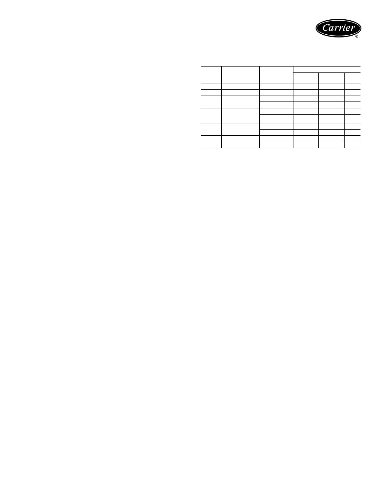
42BHC, BVC NOMINAL COOLING CAPACITIES
UNIT SIZE
42BHC,BVC
06 600
08 800
10 1000
12 1200
16
20 2000
30 3000
40 4000
EWT — Entering Water Temperature
MBtuh — Capacity (Btuh in thousands)
*Based on entering air temperature of 67 F wb, 80 F db and temperature rise of 10
degrees F.
NOTE: All ratings at sea level. Ratings in accordance with ARI (Air Conditioning &
Refrigeration Institute).
NOMINAL
LEGEND
CFM
1600
COIL
ROWS
4
6
8
4
6
8
4
6
8
4
6
8
4
6
8
4
6
8
4
6
8
4
6
8
EWT
(F)
40 23.3 16.0
45 17.9 13.8
50 12.8 12.0
40 31.0 19.8
45 24.5 17.0
50 18.0 14.5
40 33.8 21.2
45 26.7 18.1
50 19.4 15.2
40 28.4 20.0
45 21.9 17.5
50 15.3 15.3
40 38.4 25.1
45 30.3 21.7
50 22.5 18.6
40 42.6 27.2
45 33.7 23.3
50 24.7 19.8
40 40.5 27.3
45 31.6 23.7
50 23.4 20.6
40 52.2 33.3
45 41.7 28.7
50 31.2 24.5
40 57.7 36.0
45 46.4 31.0
50 34.6 26.2
40 45.4 31.2
45 35.5 27.2
50 26.5 23.8
40 59.6 38.4
45 47.4 33.2
50 35.5 28.5
40 66.6 42.0
45 53.3 36.1
50 39.9 30.7
40 59.7 41.2
45 46.4 35.9
50 34.4 31.4
40 78.7 50.9
45 62.6 44.1
50 46.8 37.8
40 89.0 56.0
45 71.3 48.3
50 53.3 41.0
40 75.2 51.6
45 59.0 45.1
50 44.1 39.5
40 99.0 63.8
45 78.7 55.2
50 59.0 47.4
40 111.8 70.3
45 89.9 60.6
50 67.6 51.6
40 112.5 77.6
45 87.6 67.6
50 65.0 59.1
40 148.5 95.8
45 117.8 82.8
50 88.1 71.1
40 168.0 105.5
45 135.0 91.0
50 101.2 77.4
40 157.7 106.7
45 123.6 92.9
50 92.6 81.1
40 204.0 130.5
45 162.6 112.7
50 122.3 96.7
40 230.1 143.5
45 185.6 123.8
50 140.2 105.2
COOLING*
Tot al
Capacity
(MBtuh)
Sensible
Capacity
(MBtuh)
42BHC,BVC NOMINAL HEATING CAPACITIES
UNIT SIZE
42BHC,BVC
06 600
08 800
10 1000
12 1200
16 1600
20 2000
30 3000
40 4000
NOTES:
1. Ratings are based on 180 F Entering Water Temperature (EWT) and 70 F
Entering Air Temperature (EAT ) .
2. Leaving-air temperature is not to exceed 104 F with the standard motor.
Consult the factory for higher temperature motor applications.
3. For information on four and six-row heating coil capacities and applications,
consult the factory.
4. For all application ratings, use the quick-selection ratings provided in this
catalog, or contact the factory.
NOMINAL CFM ROWS
127.0
246.9
127.0
246.9
127.0
246.9
138.5
268.5
148.0
287.7
158.7
2104.9
178.0
2149.2
192.3
2182.4
HEATING CAPACITY
(MBtuh)
24

UNIT
SIZE
GPM
42BHC,BVC
06
08
10
12
16
20
30
40
DB — Dry Bulb Temperature
EWT — Entering Water Temperature
MBtuh — Btuh in Thousands
SCb— Base Sensible Capacity at Nominal Cfm
TCb— Base Total Capacity at Nominal Cfm
WB — Wet Bulb Temperature
∆T—Change in Water Temperature (F)
LEGEND NOTE: All capacities are given in thousands of Btuh (MBtuh).
40 F EWT 45 F EWT 50 F EWT 40 F EWT 45 F EWT 50 F EWT 40 F EWT 45 F EWT 50 F EWT
∆TTC
3 10.9 16.3 13.2 9.0 13.5 12.1 7.2 10.7 10.7 13.0 19.5 14.5 11.1 16.6 13.4 9.1 13.7 12.3 15.3 22.9 15.7 13.3 19.9 14.6 11.2 16.9 13.5
4 9.1 18.3 14.0 7.5 15.0 12.7 5.7 11.5 11.5 11.0 22.0 15.5 9.3 18.6 14.1 7.6 15.2 12.8 13.1 26.2 16.9 11.3 22.6 15.5 9.5 18.9 14.2
5 7.9 19.7 14.6 6.4 16.1 13.1 5.0 12.5 11.6 9.6 23.9 16.3 8.0 20.1 14.7 6.5 16.2 13.2 11.4 28.5 17.8 9.8 24.5 16.3 8.2 20.4 14.8
3 12.2 18.3 16.0 10.0 15.0 15.0 8.4 12.7 12.7 14.5 21.7 17.4 12.4 18.7 16.3 10.2 15.2 15.2 16.9 25.4 18.8 14.8 22.2 17.7 12.6 19.0 16.6
4 10.4 20.8 17.0 8.6 17.2 15.6 6.9 13.8 13.8 12.4 24.9 18.6 10.6 21.1 17.2 8.7 17.4 15.8 14.6 29.2 20.2 12.7 25.4 18.8 10.7 21.4 17.4
5 9.0 22.6 17.7 7.4 18.6 16.1 5.8 14.5 14.5 10.8 27.1 19.5 9.2 22.9 17.9 7.5 18.7 16.3 12.9 32.1 21.3 11.1 27.7 19.6 9.3 23.2 18.0
6 8.0 23.9 18.3 6.5 19.5 16.5 5.0 14.9 14.9 9.6 28.9 20.3 8.1 24.3 18.4 6.6 19.7 16.7 11.5 34.4 22.1 9.8 29.5 20.3 8.2 24.6 18.5
3 15.4 23.1 20.2 12.7 19.0 19.0 10.6 16.0 16.0 18.2 27.2 22.0 15.6 23.4 20.6 12.8 19.2 19.2 21.1 31.7 23.7 18.5 27.8 22.3 15.8 23.8 21.0
4 13.2 26.4 21.6 11.0 21.9 19.8 8.8 17.5 17.5 15.7 31.5 23.6 13.4 26.8 21.8 11.1 22.1 20.1 18.4 36.9 25.5 16.0 32.0 23.8 13.6 27.1 22.1
5 11.5 28.8 22.6 9.5 23.7 20.5 7.4 18.5 18.5 13.8 34.6 24.9 11.7 29.2 22.8 9.6 23.9 20.8 16.3 40.7 27.0 14.1 35.2 24.9 11.8 29.6 22.9
6 10.2 30.6 23.4 8.4 25.1 21.1 6.4 19.1 19.1 12.3 36.9 25.8 10.4 31.1 23.5 8.4 25.3 21.3 14.6 43.8 28.2 12.6 37.7 25.8 10.5 31.5 23.6
3 16.4 24.6 22.8 13.8 20.7 20.7 11.6 17.4 17.4 19.3 28.9 24.7 16.7 25.0 23.3 14.0 20.9 20.9 22.3 33.5 26.5 19.6 29.5 25.1 16.9 25.4 23.8
4 14.2 28.4 24.3 11.9 23.7 22.4 9.7 19.3 19.3 16.8 33.6 26.5 14.4 28.8 24.6 11.6 23.2 23.2 19.6 39.2 28.5 17.1 34.2 26.7 14.5 29.1 25.0
5 12.4 31.1 25.4 10.3 25.8 23.2 8.2 20.5 20.5 14.8 37.1 27.8 12.6 31.5 25.7 10.4 26.0 23.6 17.4 43.6 30.1 15.1 37.8 28.0 12.7 31.9 25.9
6 11.1 33.2 26.3 9.1 27.3 23.9 7.1 21.4 21.4 13.3 39.8 28.9 11.2 33.7 26.5 9.2 27.5 24.2 15.6 46.9 31.4 13.5 40.5 29.0 11.3 34.0 26.7
5 14.2 35.4 31.4 11.7 29.3 29.3 9.9 24.7 24.7 16.8 41.9 34.2 14.4 36.1 32.0 11.9 29.7 29.7 19.5 48.8 36.8 17.1 42.8 34.7 14.7 36.6 32.6
7 11.8 41.3 33.8 9.8 34.3 31.0 7.8 27.4 27.4 14.1 49.4 37.1 12.0 42.0 34.2 9.9 34.6 31.5 16.6 58.0 40.1 14.4 50.3 37.3 12.1 42.5 34.6
9 10.1 45.3 35.5 8.3 37.2 32.2 6.4 28.9 28.9 12.1 54.4 39.1 10.2 46.0 35.8 8.3 37.5 32.6 14.3 64.4 42.5 12.3 55.5 39.2 10.3 46.5 36.0
11 8.7 48.1 36.7 7.1 39.3 33.0 5.4 29.9 29.9 10.6 58.3 40.7 8.9 48.8 36.9 7.2 39.5 33.3 12.6 69.3 44.4 10.8 59.4 40.6 9.0 49.5 37.0
5 16.5 41.3 37.9 13.8 34.6 34.6 11.6 29.1 29.1 19.4 48.6 41.2 16.8 42.0 38.7 14.0 35.0 35.0 22.5 56.3 44.2 19.8 49.5 41.8 17.0 42.6 39.5
7 13.9 48.5 40.8 11.6 40.5 37.6 9.3 32.7 32.7 16.5 57.6 44.6 14.0 49.2 41.4 11.7 40.8 38.3 19.2 67.4 48.1 16.7 58.6 45.0 14.2 49.7 41.9
9 11.9 53.5 42.9 9.8 44.1 39.1 7.7 34.8 34.8 14.2 64.0 47.1 12.0 54.1 43.3 9.9 44.4 39.6 16.7 75.2 51.0 14.5 65.0 47.3 12.2 54.7 43.6
11 10.4 57.1 44.4 8.5 46.8 40.1 6.6 36.1 36.1 12.5 68.6 48.9 10.5 57.8 44.7 8.5 47.0 40.6 14.8 81.3 53.3 12.7 69.9 49.0 10.6 58.4 44.9
7 15.9 55.6 55.6 13.9 48.5 48.5 11.7 41.0 41.0 19.0 66.5 59.7 16.2 56.8 56.8 14.1 49.4 49.4 22.0 77.0 64.0 19.5 68.2 61.0 16.5 57.9 57.9
9 14.6 65.5 58.6 12.1 54.4 54.4 10.2 45.8 45.8 17.2 77.4 63.7 14.8 66.8 59.8 12.2 55.1 55.1 20.0 90.1 68.5 17.6 79.0 64.7 15.1 67.8 60.9
11 13.1 72.3 61.3 11.0 60.5 56.6 8.9 49.1 49.1 15.6 85.9 67.0 13.4 73.5 62.2 11.1 61.1 57.7 18.3 100.5 72.2 15.9 87.6 67.6 13.5 74.5 63.1
14 11.4 79.9 64.5 9.4 66.1 58.8 7.5 52.3 52.3 13.7 95.6 70.7 11.6 81.1 65.1 9.5 66.6 59.7 16.1 112.5 76.6 13.9 97.4 71.1 11.7 82.1 65.7
17 11.4 85.5 66.8 8.3 70.2 60.5 6.4 54.5 54.5 12.1 102.8 73.6 10.2 86.8 67.3 8.3 70.7 61.2 14.3 121.8 80.1 12.3 104.9 73.8 10.3 87.9 67.7
11 16.4 90.5 79.5 13.5 74.4 74.4 11.4 62.5 62.5 19.4 106.8 86.4 16.7 91.8 80.8 13.7 75.1 75.1 22.6 124.1 92.8 19.7 108.5 87.4 16.9 92.8 82.1
14 14.4 100.9 83.7 12.0 84.0 76.8 9.6 67.4 67.4 17.1 119.9 91.4 14.6 102.1 84.6 12.1 84.6 78.2 20.0 140.2 98.6 17.4 121.8 92.0 14.7 103.2 85.6
17 12.8 108.7 87.0 10.6 89.7 79.2 8.3 70.6 70.6 15.3 129.9 95.4 12.9 110.0 87.6 10.6 90.2 80.2 18.0 152.6 103.2 15.5 132.0 95.7 13.1 111.1 88.3
21 11.1 116.5 90.2 9.1 95.5 81.5 7.0 73.6 73.6 13.3 140.0 99.4 11.2 118.0 90.7 9.1 95.9 82.3 15.8 165.5 108.1 13.6 142.4 99.4 11.3 119.2 91.1
25 9.8 122.3 92.7 8.0 99.8 83.2 6.0 75.6 75.6 11.8 147.9 102.7 9.9 124.0 93.0 8.0 100.3 84.0 14.1 175.8 112.1 12.0 150.4 102.4 10.0 125.5 93.3
75 F DB/ 63 F WB 80 F DB/67 F WB 85 F DB/71 F WB
∆TTCbSCb∆TTCbSCb∆TTCbSCb∆TTCbSCb∆TTCbSCb∆TTCbSCb∆TTCbSCb∆TTCbSC
bSCb
42BHC,BVC 4-ROW COOLING CAPACITY (by Gpm)
b
UNIT
SIZE
42BHC,BVC
06
08
10
12
16
20
30
40
DB — Dry Bulb Temperature
EWT — Entering Water Temperature
MBtuh — Btuh in Thousands
SCb— Base Sensible Capacity at Nominal Cfm
TCb— Base Total Capacity at Nominal Cfm
WB — Wet Bulb Temperature
∆T—Change in Water Temperature (F)
LEGEND NOTE: All capacities are given in thousands of Btuh (MBtuh).
40 F EWT 45 F EWT 50 F EWT 40 F EWT 45 F EWT 50 F EWT 40 F EWT 45 F EWT 50 F EWT
GPM
∆TTCbSCb∆TTCbSCb∆TTCbSCb∆TTCbSCb∆TTCbSCb∆TTCbSCb∆TTCbSCb∆TTCbSCb∆TTCbSC
3 13.5 20.2 15.4 11.1 16.7 13.9 8.8 13.2 12.5 16.1 24.2 16.9 13.7 20.6 15.5 11.2 16.8 14.0 19.0 28.4 18.3 16.5 24.7 16.9 13.9 20.8 15.5
4 11.3 22.6 16.4 9.2 18.5 14.6 7.2 14.4 12.9 13.6 27.2 18.2 11.5 23.0 16.4 9.3 18.6 14.7 16.1 32.2 19.8 13.9 27.9 18.1 11.7 23.4 16.4
5 9.7 24.2 17.1 7.9 19.7 15.1 6.1 15.1 13.3 11.7 29.2 19.1 9.9 24.6 17.1 7.9 19.9 15.2 13.9 34.8 20.9 12.0 30.0 19.0 10.0 25.1 17.1
3 15.3 22.9 18.7 12.8 19.2 17.2 10.2 15.3 15.3 18.1 27.2 20.4 15.5 23.3 18.9 12.9 19.3 17.4 21.2 31.8 22.0 18.5 27.7 20.5 15.7 23.6 19.1
4 13.0 26.0 20.0 10.7 21.4 18.1 8.3 16.5 16.5 15.5 31.1 22.0 13.2 26.4 20.1 10.8 21.6 18.3 18.3 36.5 23.8 15.8 31.7 22.0 13.4 26.7 20.2
5 11.3 28.1 20.9 9.2 23.1 18.7 7.2 18.0 16.7 13.5 33.8 23.1 11.4 28.6 21.0 9.3 23.2 18.9 16.0 40.0 25.2 13.8 34.6 23.1 11.6 29.0 21.0
6 9.9 29.7 21.6 8.1 24.3 19.2 6.3 18.8 17.0 12.0 35.9 24.0 10.1 30.2 21.6 8.2 24.5 19.3 14.2 42.6 26.2 12.2 36.7 23.9 10.2 30.7 21.6
4 16.2 32.3 25.0 13.4 26.8 22.7 10.4 20.8 20.8 19.2 38.5 27.4 16.4 32.7 25.1 13.5 26.9 22.9 22.5 45.0 29.6 19.5 39.1 27.4 16.5 33.1 25.2
5 14.1 35.3 26.3 11.6 29.0 23.6 9.1 22.8 21.1 16.9 42.3 29.0 14.3 35.8 26.3 11.7 29.2 23.8 19.9 49.8 31.5 17.2 43.0 28.9 14.5 36.2 26.3
6 12.5 37.5 27.2 10.2 30.6 24.3 7.9 23.8 21.5 15.0 45.1 30.2 12.7 38.1 27.2 10.3 30.8 24.4 17.8 53.3 32.9 15.4 46.1 30.0 12.9 38.6 27.2
8 10.1 40.5 28.6 8.2 32.9 25.3 6.3 25.3 22.1 12.3 49.1 31.9 10.3 41.3 28.5 8.3 33.2 25.3 14.6 58.5 35.0 12.6 50.3 31.7 10.5 41.9 28.4
6 13.7 41.0 30.8 11.2 33.6 27.7 8.8 26.5 24.8 16.4 49.1 33.9 13.8 41.5 30.9 11.3 33.8 27.9 19.3 57.8 36.8 16.6 49.9 33.8 14.0 41.9 30.9
8 11.2 44.7 32.4 9.1 36.4 28.9 7.1 28.2 25.5 13.5 53.9 35.9 11.3 45.4 32.4 9.2 36.7 29.0 16.0 63.9 39.3 13.8 55.0 35.8 11.5 46.0 32.4
10 9.4 47.1 33.5 7.7 38.3 29.7 5.9 29.4 26.0 11.5 57.3 37.4 9.6 48.0 33.5 7.7 38.6 29.7 13.6 68.2 41.1 11.7 58.6 37.2 9.8 48.8 33.4
7 14.6 51.2 39.6 12.1 42.3 35.9 9.4 32.8 32.8 17.5 61.1 43.5 14.8 51.9 39.8 12.2 42.6 36.3 20.5 71.7 47.0 17.8 62.1 43.5 15.0 52.4 40.0
9 12.5 56.1 41.7 10.2 46.0 37.4 8.0 36.0 33.3 15.0 67.4 46.0 12.6 56.9 41.8 10.3 46.2 37.6 17.7 79.5 50.1 15.3 68.7 45.9 12.8 57.6 41.8
11 10.8 59.5 43.2 8.8 48.5 38.5 6.8 37.6 34.0 13.1 71.8 47.9 11.0 60.5 43.2 8.9 48.9 38.6 15.5 85.2 52.4 13.3 73.4 47.7 11.1 61.3 43.2
13 9.5 62.0 44.4 7.8 50.5 39.3 6.0 38.8 34.5 11.6 75.3 49.4 9.7 63.2 44.3 7.8 50.9 39.4 13.8 89.6 54.2 11.8 76.9 49.1 9.9 64.2 44.2
7 17.0 59.6 47.6 14.2 49.5 43.4 11.2 39.2 39.2 20.2 70.7 52.0 17.2 60.3 47.9 14.2 49.8 44.0 23.6 82.5 56.0 20.5 71.7 52.1 17.4 60.8 48.2
9 14.6 65.9 50.2 12.0 54.2 45.3 9.2 41.5 41.5 17.5 78.7 55.2 14.8 66.6 50.4 12.1 54.5 45.7 20.5 92.4 59.8 17.8 79.9 55.1 14.9 67.3 50.5
11 12.8 70.4 52.2 10.5 57.6 46.7 8.2 45.0 41.6 15.4 84.6 57.6 13.0 71.3 52.2 10.5 57.9 47.0 18.1 99.8 62.7 15.6 86.1 57.4 13.1 72.1 52.2
13 11.4 73.8 53.7 9.3 60.2 47.8 7.2 46.6 42.3 13.7 89.0 59.5 11.5 74.9 53.6 9.3 60.5 48.0 16.2 105.3 64.9 14.0 90.8 59.2 11.7 75.9 53.6
15 10.2 76.5 54.9 8.3 62.2 48.7 6.4 47.9 42.8 12.3 92.6 61.0 10.4 77.8 54.8 8.4 62.6 48.8 14.7 110.2 67.0 12.6 94.6 60.7 10.5 78.9 54.7
11 16.3 89.4 71.5 13.5 74.4 65.3 10.7 59.0 59.0 19.3 106.2 78.1 16.5 90.6 72.1 13.6 75.0 66.2 22.5 124.0 84.3 19.6 107.9 78.4 16.7 91.6 72.7
14 14.1 98.9 75.5 11.6 81.5 68.2 8.9 62.5 62.5 16.9 118.2 83.0 14.3 100.2 75.8 11.7 82.0 68.8 19.8 138.9 90.0 17.2 120.3 82.9 14.5 101.3 76.0
17 12.4 105.8 78.5 10.2 86.7 70.3 8.0 67.8 62.7 15.0 127.2 86.7 12.6 107.3 78.6 10.3 87.2 70.8 17.6 150.0 94.3 15.2 129.6 86.4 12.8 108.6 78.7
21 10.7 112.5 81.5 8.7 91.7 72.4 6.8 71.0 63.9 12.9 135.8 90.4 10.9 114.3 81.4 8.8 92.3 72.7 15.4 161.2 98.8 13.2 138.8 89.9 11.0 115.9 81.3
17 15.6 132.8 101.1 12.9 109.4 91.3 10.2 86.6 82.1 18.7 158.6 111.1 15.8 134.3 101.4 12.9 109.9 92.0 21.9 185.9 120.3 18.9 160.8 110.8 15.9 135.4 101.6
21 13.6 142.7 105.4 11.1 116.8 94.3 8.7 91.3 83.9 16.3 171.3 116.4 13.8 144.5 105.4 11.2 117.3 94.8 19.2 201.8 126.5 16.6 174.2 115.8 13.9 145.9 105.3
25 12.0 150.0 108.6 9.8 122.3 96.6 7.6 94.8 85.3 14.5 180.8 120.4 12.2 152.2 108.5 9.8 123.0 97.0 17.1 213.8 131.4 14.7 184.4 119.7 12.3 154.1 108.3
75 F DB/63 F WB 80 F DB/67 F WB 85 F DB/71 F WB
42BHC,BVC 6-ROW COOLING CAPACITY (by Gpm)
b
25

Performance data (cont)
42BHC,BVC 8-ROW COOLING CAPACITY (by Gpm)
UNIT
SIZE
42BHC,BVC
06
08
10
12
16
20
30
40
DB — Dr y Bulb Temperature
EWT — Entering Water Temperature
MBtuh — Btuh in Thousands
SCb— Base Sensible Capacity at Nominal Cfm
TCb— Base Total Capacity at Nominal Cfm
WB — Wet Bulb Temperature
∆T—Change in Water Temperature (F)
42BHC,BVC
DB — Dry Bulb Temperature
EWT — Entering Water Temperature
MBtuh — Btuh in Thousands
SCb— Base Sensible Capacity at Nominal Cfm
TCb— Base Total Capacity at Nominal Cfm
WB — Wet Bulb Temperature
∆T—Change in Water Temperature (F)
LEGEND NOTE: All capacities are given in thousands of Btuh (MBtuh).
UNIT
SIZE
06
08
10
12
16
20
30
40
LEGEND NOTE: All capacities are given in thousands of Btuh (MBtuh).
40 F EWT 45 F EWT 50 F EWT 40 F EWT 45 F EWT 50 F EWT 40 F EWT 45 F EWT 50 F EWT
GPM
∆TTC
4 11.8 23.6 17.0 9.7 19.4 15.2 7.6 15.1 13.4 14.2 28.4 18.9 12.1 24.1 17.1 9.8 19.6 15.3 16.8 33.6 20.6 14.6 29.2 18.8 12.3 24.6 17.1
5 10.2 25.6 17.9 8.4 20.9 15.8 6.4 16.1 13.8 12.4 30.9 20.0 10.5 26.2 17.9 8.5 21.2 15.9 14.7 36.7 21.9 12.7 31.9 19.9 10.7 26.7 17.9
6 9.0 27.0 18.6 7.3 22.0 16.3 5.6 16.8 14.1 10.9 32.7 20.8 9.2 27.6 18.5 7.4 22.3 16.3 13.0 39.0 22.9 11.3 33.8 20.6 9.4 28.3 18.5
7 8.0 28.0 19.0 6.5 22.8 16.7 5.0 17.3 14.3 9.7 34.1 21.4 8.2 28.7 19.0 6.6 23.1 16.7 11.6 40.7 23.6 10.1 35.2 21.2 8.4 29.4 18.9
4 13.6 27.2 20.8 11.3 22.5 18.8 9.0 18.0 17.0 16.2 32.5 22.8 13.8 27.7 20.9 11.4 22.8 19.0 19.0 38.1 24.7 16.6 33.2 22.9 14.1 28.1 21.0
5 11.9 29.9 21.9 9.8 24.6 19.7 7.7 19.3 17.5 14.4 35.9 24.2 12.2 30.4 22.0 9.9 24.8 19.8 16.9 42.3 26.4 14.7 36.7 24.2 12.4 30.9 22.0
6 10.6 31.9 22.8 8.7 26.1 20.3 6.7 20.2 17.9 12.8 38.4 25.3 10.8 32.5 22.8 8.8 26.4 20.4 15.2 45.5 27.7 13.1 39.4 25.2 11.0 33.1 22.8
7 9.5 33.4 23.5 7.8 27.2 20.8 6.0 21.0 18.2 11.5 40.4 26.2 9.7 34.1 23.5 7.9 27.6 20.9 13.7 47.9 28.7 11.9 41.5 26.1 9.9 34.8 23.5
8 8.6 34.6 24.1 7.0 28.2 21.2 5.4 21.6 18.4 10.5 41.9 26.9 8.8 35.4 24.0 7.1 28.5 21.2 12.5 50.0 29.6 10.8 43.2 26.7 9.0 36.1 24.0
6 13.3 40.0 28.6 10.9 32.8 25.5 8.5 25.5 22.5 16.0 48.1 31.7 13.6 40.7 28.6 11.0 33.1 25.6 18.9 56.8 34.6 16.4 49.2 31.6 13.8 41.3 28.6
7 12.0 42.1 29.6 9.8 34.4 26.2 7.6 26.5 22.9 14.5 50.8 32.9 12.3 42.9 29.5 9.9 34.7 26.2 17.2 60.2 36.0 14.9 52.1 32.7 12.5 43.6 29.4
8 10.9 43.7 30.3 8.9 35.6 26.7 6.8 27.3 23.2 13.2 52.9 33.8 11.2 44.6 30.3 9.0 36.0 26.7 15.7 62.8 37.2 13.6 54.4 33.6 11.4 45.5 30.1
9 10.0 45.0 31.0 8.1 36.6 27.2 6.2 28.0 23.5 12.1 54.6 34.6 10.2 46.0 30.8 8.2 37.1 27.2 14.5 65.1 38.1 12.5 56.2 34.4 10.4 47.0 30.7
7 13.2 46.4 33.6 10.9 38.0 30.0 8.5 29.7 26.5 15.9 55.7 37.1 13.5 47.1 33.6 10.9 38.3 30.1 18.8 65.7 40.5 16.3 56.9 37.0 13.6 47.8 33.5
9 11.1 50.1 35.3 9.1 40.8 31.2 7.0 31.5 27.3 13.5 60.5 39.2 11.3 51.0 35.2 9.2 41.2 31.2 15.9 71.7 43.0 13.8 62.0 39.0 11.5 51.9 35.1
11 9.6 52.6 36.4 7.8 42.8 32.0 5.9 32.7 27.8 11.6 63.8 40.7 9.8 53.7 36.3 7.9 43.2 32.0 13.8 76.1 44.8 11.9 65.5 40.4 10.0 54.8 36.1
13 8.4 54.4 37.2 6.8 44.2 32.6 5.2 33.6 28.1 10.2 66.3 41.8 8.6 55.6 37.1 6.9 44.7 32.6 12.2 79.1 46.2 10.5 68.2 41.5 8.7 56.9 37.0
9 13.6 61.0 44.5 11.1 50.1 39.7 8.7 39.2 35.3 16.3 73.3 49.1 13.8 62.1 44.5 11.2 50.6 39.9 19.2 86.4 53.5 16.6 74.9 48.9 14.0 63.0 44.4
11 11.9 65.3 46.4 9.7 53.3 41.1 7.5 41.2 36.1 14.3 78.8 51.5 12.1 66.5 46.3 9.8 53.8 41.2 16.9 93.2 56.3 14.7 80.6 51.2 12.3 67.5 46.1
13 10.5 68.3 47.7 8.6 55.7 42.1 6.6 42.7 36.7 12.7 82.7 53.2 10.7 69.7 47.6 8.6 56.2 42.1 15.1 98.2 58.4 13.1 84.9 52.9 10.9 70.9 47.4
15 9.4 70.6 48.8 7.7 57.4 42.9 5.8 43.9 37.1 11.4 85.8 54.6 9.6 72.2 48.6 7.7 58.0 42.9 13.6 102.3 60.1 11.7 88.1 54.2 9.8 73.6 48.4
10 14.9 74.6 54.8 12.3 61.3 49.1 9.6 48.1 43.7 17.9 89.4 60.4 15.1 75.7 54.8 12.3 61.7 49.3 21.0 105.1 65.6 18.2 91.0 60.1 15.3 76.5 54.7
12 13.2 79.4 56.9 10.8 64.9 50.6 8.4 50.4 44.6 15.9 95.6 63.0 13.4 80.6 56.8 10.9 65.4 50.7 18.8 112.8 68.8 16.3 97.5 62.6 13.6 81.7 56.6
14 11.9 83.0 58.6 9.7 67.7 51.8 7.4 52.2 45.3 14.3 100.3 65.1 12.1 84.5 58.4 9.7 68.2 51.8 17.0 118.7 71.2 14.6 102.6 64.6 12.2 85.7 58.1
16 10.7 85.8 59.8 8.7 69.8 52.7 6.7 53.5 45.8 13.0 103.9 66.7 10.9 87.5 59.6 8.8 70.4 52.7 15.4 123.5 73.3 13.3 106.5 66.2 11.1 89.0 59.3
13 16.1 104.3 78.9 13.3 86.4 71.3 10.6 68.7 64.2 19.2 124.5 86.7 16.3 105.9 79.2 13.4 87.1 72.0 22.4 145.9 93.8 19.5 126.8 86.6 16.5 107.2 79.5
16 14.2 113.6 83.0 11.7 93.3 74.2 9.1 73.1 65.9 17.0 136.3 91.6 14.4 115.4 83.0 11.8 94.0 74.6 20.1 160.5 99.6 17.4 139.0 91.2 14.6 116.9 82.9
19 12.7 120.5 86.1 10.4 98.5 76.4 8.0 76.4 67.3 15.3 145.2 95.4 12.9 122.6 85.9 10.5 99.4 76.6 18.1 171.6 104.2 15.6 148.4 94.8 13.1 124.4 85.7
22 11.4 125.8 88.5 9.3 102.6 78.2 7.2 79.0 68.3 13.8 152.0 98.4 11.6 128.1 88.2 9.4 103.5 78.2 16.4 180.2 107.8 14.2 155.7 97.7 11.8 130.2 87.9
25 10.4 129.9 90.3 8.5 105.7 79.5 6.5 81.0 69.1 12.6 157.4 100.8 10.6 132.5 90.0 8.5 106.7 79.5 15.0 187.2 110.8 12.9 161.5 100.0 10.8 134.9 89.6
19 15.9 151.5 110.7 13.1 124.5 99.0 10.3 97.7 88.0 19.1 181.4 122.0 16.1 153.4 110.5 13.2 125.2 99.4 22.4 213.0 132.5 19.4 184.3 121.2 16.3 155.0 110.3
22 14.5 159.4 114.3 11.9 130.4 101.5 9.2 101.4 89.5 17.4 191.6 126.4 14.7 161.7 113.8 11.9 131.2 101.7 20.5 225.8 137.7 17.7 195.1 125.4 14.9 163.6 113.4
25 13.3 165.7 117.1 10.8 135.2 103.6 8.4 104.4 90.7 16.0 199.7 129.9 13.5 168.3 116.6 10.9 136.1 103.6 18.9 236.1 142.0 16.3 203.9 128.8 13.6 170.6 116.0
28 12.2 170.8 119.3 9.9 139.0 105.2 7.6 106.9 91.7 14.7 206.4 132.8 12.4 173.8 118.8 10.0 140.1 105.2 17.5 244.4 145.5 15.1 211.1 131.7 12.6 176.4 118.2
40 F EWT 45 F EWT 50 F EWT 40 F EWT 45 F EWT 50 F EWT 40 F EWT 45 F EWT 50 F EWT
∆T
GPM TCbSCbGPM TCbSCbGPM TCbSCbGPM TCbSCbGPM TCbSCbGPM TCbSCbGPM TCbSCbGPM TCbSCbGPM TCbSC
10 3.5 17.3 13.6 2.5 12.5 11.7 3.5 17.3 13.6 4.7 23.3 16.0 3.6 17.9 13.8 2.6 12.8 12.0 6.0 30.0 18.5 4.8 24.2 16.2 3.7 18.3 14.0
12 2.5 14.9 12.6 — — — 2.5 14.9 12.6 3.5 20.8 15.0 2.6 15.5 12.9 — — — 4.6 27.7 17.5 3.6 21.7 15.2 2.7 16.0 13.2
14 — — — — — — — — — 2.6 18.1 13.9 — — — — — — 3.5 24.8 16.4 2.7 19.0 14.2 — — —
16— — ————— — —— — —— — — ——— 2.721.815.3— — —— — —
10 4.3 21.3 17.2 3.0 15.1 15.1 4.3 21.3 17.2 5.7 28.4 20.0 4.4 21.9 17.5 3.1 15.3 15.3 7.3 36.4 22.9 5.8 29.2 20.2 4.5 22.3 17.7
12 3.1 18.6 16.1 2.2 13.3 13.3 3.1 18.6 16.1 4.2 25.5 18.9 3.2 19.3 16.5 2.3 13.7 13.7 5.6 33.5 21.8 4.4 26.4 19.1 3.3 19.8 16.8
14 2.3 15.8 15.0 — — — 2.3 15.8 15.0 3.2 22.5 17.7 2.4 16.5 15.5 — — — 4.3 30.2 20.6 3.3 23.4 18.1 2.5 17.2 16.0
16 — — — — — — — — — 2.4 19.3 16.5 — — — — — — 3.4 27.0 19.3 2.5 20.3 17.0 — — —
18— — ————— — —— — —— — — ——— 2.623.418.1— — —— — —
10 6.2 30.9 23.5 4.6 23.1 20.3 6.2 30.9 23.5 8.1 40.5 27.3 6.3 31.6 23.7 4.7 23.4 20.6 10.2 51.2 31.1 8.4 41.8 27.4 6.4 32.2 23.9
12 4.7 28.1 22.3 3.4 20.7 19.3 4.7 28.1 22.3 6.2 37.3 26.0 4.8 28.8 22.6 3.5 21.0 19.7 8.0 47.9 29.8 6.4 38.5 26.1 4.9 29.4 22.9
14 3.6 25.2 21.1 2.5 17.6 17.6 3.6 25.2 21.1 4.9 34.3 24.8 3.7 25.9 21.5 2.6 18.1 18.1 6.4 44.7 28.5 5.0 35.4 25.0 3.8 26.5 21.9
16 2.8 22.0 19.8 — — — 2.8 22.0 19.8 3.9 31.0 23.5 2.9 22.9 20.4 — — — 5.2 41.2 27.2 4.0 32.1 23.8 2.9 23.5 20.9
18 — — — — — — — — — 3.1 27.5 22.1 — — — — — — 4.2 37.7 25.8 3.2 28.6 22.6 2.2 19.5 19.5
10 7.0 34.8 27.0 5.2 26.2 23.4 7.0 34.8 27.0 9.1 45.4 31.2 7.1 35.5 27.2 5.3 26.5 23.8 11.5 57.5 35.5 9.3 46.8 31.3 7.2 36.1 27.4
12 5.3 31.8 25.7 3.9 23.6 22.4 5.3 31.8 25.7 7.0 41.9 29.8 5.4 32.5 26.0 3.8 22.9 22.9 9.0 53.8 34.0 7.2 43.1 29.9 5.5 33.0 26.3
14 4.1 28.6 24.4 2.9 20.4 20.4 4.1 28.6 24.4 5.5 38.6 28.4 4.2 29.4 24.9 3.0 20.9 20.9 7.2 50.1 32.6 5.7 39.7 28.7 4.3 29.9 25.3
16 3.2 25.3 23.0 2.2 17.8 17.8 3.2 25.3 23.0 4.4 35.1 27.0 3.3 26.1 23.7 2.3 18.5 18.5 5.8 46.3 31.1 4.5 36.1 27.4 3.4 26.8 24.2
18 2.3 21.0 21.0 — — — 2.3 21.0 21.0 3.5 31.4 25.6 2.4 21.9 21.9 — — — 4.7 42.4 29.7 3.6 32.5 26.2 2.5 22.6 22.6
10 9.1 45.4 35.6 6.8 33.9 30.8 9.1 45.4 35.6 11.9 59.7 41.2 9.3 46.4 35.9 6.9 34.4 31.4 15.2 75.8 47.0 12.3 61.4 41.4 9.5 47.3 36.3
12 6.8 40.9 33.7 4.8 28.9 28.9 6.8 40.9 33.7 9.1 54.7 39.2 7.0 41.9 34.2 4.9 29.5 29.5 11.8 70.6 44.9 9.4 56.3 39.5 7.1 42.8 34.7
14 5.1 35.9 31.6 3.6 25.2 25.2 5.1 35.9 31.6 7.1 49.6 37.2 5.3 37.2 32.4 3.7 26.2 26.2 9.3 65.3 42.9 7.3 51.3 37.7 5.5 38.2 33.2
16 3.6 28.9 28.9 — — — 3.6 28.9 28.9 5.5 44.1 35.1 3.8 30.3 30.3 — — — 7.4 59.6 40.7 5.7 45.9 35.8 4.2 33.4 31.6
18 — — — — — — — — — 4.2 38.0 32.8 — — — — — — 6.0 53.7 38.5 4.5 40.1 33.8 — — —
10 11.6 57.9 44.8 8.7 43.7 38.9 11.6 57.9 44.8 15.0 75.2 51.6 11.8 59.0 45.1 8.8 44.1 39.5 19.1 95.4 58.8 15.5 77.6 51.9 12.0 60.0 45.5
12 8.9 53.2 42.8 6.6 39.5 37.2 8.9 53.2 42.8 11.6 69.9 49.4 9.0 54.2 43.3 6.7 40.1 38.0 14.9 89.6 56.5 12.0 71.7 49.7 9.2 55.1 43.8
14 6.9 48.1 40.7 4.9 34.2 34.2 6.9 48.1 40.7 9.2 64.6 47.3 7.0 49.3 41.4 5.0 35.0 35.0 11.9 83.4 54.1 9.5 66.3 47.7 7.2 50.2 42.1
16 5.3 42.8 38.5 3.8 30.0 30.0 5.3 42.8 38.5 7.4 59.0 45.1 5.5 44.1 39.5 3.9 31.2 31.2 9.7 77.4 51.8 7.6 60.7 45.7 5.6 45.2 40.4
18 3.9 35.4 35.4 — — — 3.9 35.4 35.4 5.9 53.1 42.8 4.1 36.9 36.9 — — — 7.9 71.3 49.5 6.1 54.8 43.7 4.2 38.0 38.0
10 17.2 85.8 66.9 12.8 64.1 58.0 17.2 85.8 66.9 22.5 112.5 77.6 17.5 87.6 67.6 13.0 65.0 59.1 28.6 142.8 88.4 23.1 115.8 77.8 17.8 89.2 68.2
12 12.9 77.4 63.4 9.1 54.7 54.7 12.9 77.4 63.4 17.2 103.3 73.8 13.2 79.4 64.5 9.3 55.8 55.8 22.1 132.7 84.4 17.7 106.4 74.4 13.5 81.0 65.3
14 9.8 68.3 59.7 6.8 47.9 47.9 9.8 68.3 59.7 13.4 94.0 70.1 10.1 70.6 61.2 7.1 49.8 49.8 17.6 123.3 80.7 13.9 97.0 71.0 10.4 72.5 62.5
16 6.9 55.2 55.2 — — — 6.9 55.2 55.2 10.5 84.0 66.2 7.6 61.1 57.7 — — — 14.1 112.9 76.8 10.9 87.2 67.5 7.9 63.5 59.5
18 — — — — — — — — — 8.1 72.8 62.0 — — — — — — 11.3 102.0 72.8 8.5 76.6 63.9 — — —
14 14.7 102.9 84.5 10.4 72.8 72.8 14.7 102.9 84.5 19.5 136.6 98.0 15.0 105.0 85.7 10.6 74.1 74.1 25.1 175.5 112.0 20.0 140.1 98.6 15.2 106.7 86.8
16 11.6 92.9 80.4 8.2 65.3 65.3 11.6 92.9 80.4 15.8 126.1 93.9 11.9 95.2 82.1 8.4 67.2 67.2 20.5 163.8 107.5 16.2 129.4 94.7 12.1 97.1 83.5
18 9.1 81.9 76.0 6.1 55.2 55.2 9.1 81.9 76.0 12.8 115.0 89.5 9.4 84.8 78.3 6.5 58.5 58.5 16.9 152.4 103.1 13.1 118.4 90.8 9.7 87.2 80.2
75 F DB / 63 F WB 80 F DB / 67 F WB 85 F DB / 71 F WB
b SC
∆TTCbSCb∆TTCbSCb∆TTCbSCb∆TTCbSCb∆TTCbSCb∆TTCbSCb∆TTCbSCb∆TTCbSC
b
42BHC,BVC 4-ROW COOLING CAPACITY (by ∆T)
75 F DB/ 63 F WB 80 F DB/67 F WB 85 F DB/71 F WB
b
b
26

42BHC, BVC 6-ROW COOLING CAPACITY (by ∆T)
UNIT
SIZE
42BHC,BVC
06
08
10
12
16
20
30
40
DB — Dr y Bulb Temperature TCb— Base Total Capacity at Nominal Cfm
EWT — Entering Water Temperature WB — Wet Bulb Temperature
MBtuh — Btuh in Thousands ∆T—Change in Water Temperature (F)
SCb— Base Sensible Capacity at Nominal Cfm
40 F EWT 45 F EWT 50 F EWT 40 F EWT 45 F EWT 50 F EWT 40 F EWT 45 F EWT 50 F EWT
∆T
GPM TCbSCbGPM T CbSCbGPM TCbSCbGPM TCbSCbGPM TCbSCbGPM TCbSCbGPM TCbSCbGPM TCbSCbGPM TCbSC
10 4.8 23.8 17.0 3.5 17.7 14.3 2.4 12.0 12.0 6.2 31.0 19.8 4.9 24.5 17.0 3.6 18.0 14.5 7.8 38.8 22.7 6.4 32.2 19.9 5.0 25.1 17.1
12 3.6 21.8 16.1 2.6 15.8 13.5 — — — 4.8 28.9 18.9 3.7 22.4 16.2 2.7 16.1 13.8 6.2 37.0 21.9 5.0 30.0 19.0 3.8 23.0 16.3
14 2.8 19.6 15.1 — — — — — — 3.8 26.7 18.0 2.9 20.2 15.3 — — — 5.0 34.7 20.9 4.0 27.8 18.1 3.0 20.7 15.5
16 — — — — — — — — — 3.0 24.3 17.0 2.2 17.8 14.4 — — — 4.0 32.3 19.9 3.2 25.3 17.1 2.3 18.4 14.7
18 — — — — — — — — — 2.4 21.7 15.9 — — — — — — 3.3 29.8 18.9 2.5 22.7 16.2 — — —
10 5.9 29.6 21.6 4.4 22.2 18.4 3.1 15.5 15.5 7.7 38.4 25.1 6.1 30.3 21.7 4.5 22.5 18.6 9.7 48.3 28.6 8.0 39.8 25.1 6.2 31.0 21.7
12 4.5 27.2 20.5 3.3 20.0 17.5 2.3 14.0 14.0 6.0 35.8 23.9 4.6 27.9 20.7 3.4 20.3 17.8 7.6 45.6 27.5 6.2 37.1 24.0 4.7 28.5 20.8
14 3.5 24.7 19.4 2.5 17.7 16.6 — — — 4.7 33.2 22.8 3.6 25.3 19.7 2.6 18.1 17.0 6.1 42.9 26.3 4.9 34.3 23.0 3.7 25.8 19.9
16 2.7 21.9 18.3 — — — — — — 3.8 30.4 21.7 2.8 22.6 18.7 — — — 5.0 40.0 25.2 3.9 31.4 21.9 2.9 23.2 19.0
18 — — — — — — — — — 3.0 27.4 20.5 2.2 19.9 17.6 — — — 4.1 37.0 24.0 3.2 28.4 20.8 2.3 20.5 18.1
10 8.1 40.6 28.7 6.2 30.9 24.4 4.4 22.0 20.7 10.4 52.2 33.3 8.3 41.7 28.7 6.2 31.2 24.5 13.0 65.1 37.9 10.8 54.2 33.3 8.5 42.6 28.7
12 6.4 38.1 27.5 4.7 28.5 23.4 3.3 19.7 19.7 8.3 49.5 32.1 6.5 39.0 27.6 4.8 28.8 23.6 10.4 62.4 36.7 8.5 51.1 32.0 6.6 39.8 27.7
14 5.1 35.4 26.3 3.7 26.0 22.4 2.6 17.9 17.9 6.7 46.7 30.8 5.2 36.2 26.5 3.8 26.3 22.7 8.5 59.4 35.4 6.9 48.1 30.8 5.3 36.9 26.6
16 4.1 32.5 25.1 2.9 23.3 21.3 — — — 5.5 43.7 29.6 4.2 33.3 25.3 3.0 23.7 21.7 7.0 56.2 34.1 5.6 45.0 29.6 4.2 33.9 25.5
18 3.3 29.5 23.8 2.2 19.9 19.9 — — — 4.5 40.6 28.2 3.4 30.2 24.1 2.3 20.4 20.4 5.9 53.0 32.7 4.6 41.7 28.4 3.4 30.8 24.5
10 9.3 46.3 33.2 7.0 35.2 28.4 4.9 24.4 24.4 11.9 59.6 38.4 9.5 47.4 33.2 7.1 35.5 28.5 14.9 74.3 43.7 12.3 61.7 38.4 9.7 48.4 33.2
12 7.2 43.5 31.9 5.4 32.6 27.3 3.8 22.8 22.8 9.4 56.3 37.0 7.4 44.3 32.0 5.5 32.8 27.5 11.8 71.1 42.3 9.7 58.0 36.9 7.5 45.1 32.1
14 5.8 40.4 30.6 4.3 29.8 26.1 3.0 20.9 20.9 7.6 53.0 35.6 5.9 41.2 30.7 4.3 30.1 26.5 9.7 67.6 40.8 7.8 54.6 35.6 6.0 41.9 30.9
16 4.7 37.2 29.2 3.4 27.0 25.0 2.3 18.4 18.4 6.2 49.7 34.2 4.7 38.0 29.5 3.4 27.4 25.5 8.0 63.7 39.2 6.4 51.1 34.3 4.8 38.6 29.7
18 3.8 33.9 27.8 2.6 23.3 23.3 — — — 5.1 46.2 32.7 3.8 34.6 28.2 2.6 23.8 23.8 6.7 60.1 37.8 5.3 47.4 32.9 3.9 35.2 28.6
10 12.2 61.2 44.0 9.3 46.4 37.6 6.4 32.1 32.1 15.7 78.7 50.9 12.5 62.6 44.1 9.4 46.8 37.8 19.7 98.5 58.0 16.3 81.5 50.9 12.8 63.9 44.1
12 9.5 57.0 42.1 7.1 42.5 36.0 4.9 29.7 29.7 12.4 74.2 48.9 9.7 58.3 42.3 7.2 42.9 36.4 15.6 93.9 56.0 12.8 76.5 48.9 9.9 59.4 42.5
14 7.5 52.6 40.2 5.5 38.4 34.3 3.8 26.6 26.6 10.0 69.7 47.0 7.7 53.8 40.5 5.6 39.0 34.9 12.7 89.1 54.0 10.3 71.8 47.1 7.8 54.8 40.8
16 6.0 47.8 38.2 4.1 32.6 32.6 — — — 8.1 64.8 45.0 6.1 49.0 38.7 4.2 33.4 33.4 10.5 83.7 51.8 8.3 66.8 45.2 6.3 50.0 39.2
18 4.7 42.7 36.0 — — — — — — 6.6 59.6 42.9 4.9 44.0 36.8 3.3 29.8 29.8 8.7 78.6 49.7 6.8 61.5 43.2 5.0 45.1 37.5
10 15.4 76.9 55.1 11.7 58.6 47.1 8.1 40.6 40.6 19.8 99.0 63.8 15.7 78.7 55.2 11.8 59.0 47.4 24.7 123.3 72.5 20.4 102.1 63.6 16.1 80.3 55.2
12 12.0 72.3 53.0 9.1 54.3 45.4 6.3 38.1 38.1 15.6 93.6 61.5 12.3 73.7 53.2 9.1 54.7 45.8 19.7 117.9 70.2 16.0 96.3 61.3 12.5 75.0 53.3
14 9.6 67.4 50.9 7.1 49.9 43.6 5.0 35.0 35.0 12.6 88.2 59.2 9.8 68.7 51.2 7.2 50.4 44.2 16.0 112.0 67.7 13.0 90.7 59.2 10.0 69.7 51.4
16 7.8 62.3 48.7 5.7 45.3 41.7 3.9 31.0 31.0 10.4 82.9 56.9 7.9 63.5 49.1 5.7 45.9 42.6 13.3 106.1 65.3 10.6 85.1 57.0 8.1 64.4 49.5
18 6.3 56.9 46.4 4.3 39.1 39.1 — — — 8.6 77.3 54.6 6.5 58.1 47.1 4.4 40.0 40.0 11.1 100.2 62.9 8.8 79.2 54.8 6.6 59.1 47.6
10 23.0 115.1 82.6 17.5 87.3 70.6 12.1 60.5 60.5 29.7 148.5 95.8 23.6 117.8 82.8 17.6 88.1 71.1 37.0 185.2 109.0 30.6 153.2 95.6 24.1 120.3 82.9
12 17.9 107.5 79.3 13.4 80.2 67.6 9.3 56.0 56.0 23.3 139.8 92.1 18.3 109.9 79.6 13.5 81.0 68.4 29.3 176.0 105.0 24.0 144.1 92.0 18.6 111.9 79.8
14 14.2 99.3 75.7 10.4 72.6 64.6 7.2 50.3 50.3 18.8 131.3 88.4 14.5 101.5 76.3 10.5 73.7 65.7 23.9 167.6 101.5 19.3 135.3 88.6 14.8 103.3 76.8
16 11.3 90.6 72.0 7.7 61.8 61.8 — — — 15.3 122.4 84.7 11.6 92.8 72.9 7.9 63.2 63.2 19.7 157.8 97.5 15.7 126.0 85.0 11.8 94.5 73.7
18 9.0 81.1 68.0 6.1 54.6 54.6 — — — 12.5 112.9 80.8 9.3 83.5 69.4 6.3 56.7 56.7 16.5 148.3 93.6 12.9 116.2 81.4 9.5 85.5 70.6
10 31.8 158.9 112.7 24.3 121.4 96.3 17.4 87.2 82.3 40.8 204.0 130.5 32.5 162.6 112.7 24.5 122.3 96.7 — — — 42.2 210.9 130.2 33.2 166.2 112.7
12 25.0 150.0 108.6 18.9 113.1 92.8 13.1 78.8 78.8 32.3 193.6 125.9 25.5 153.0 108.8 19.0 113.9 93.5 40.6 243.4 143.8 33.3 199.6 125.7 26.0 155.7 108.9
14 20.1 140.7 104.6 14.9 104.6 89.3 10.4 73.1 73.1 26.2 183.1 121.4 20.5 143.3 104.9 15.1 105.4 90.4 33.2 232.4 139.1 26.9 188.5 121.3 20.8 145.4 105.1
16 16.4 131.0 100.3 12.0 95.7 85.7 8.2 66.0 66.0 21.6 172.9 117.0 16.7 133.2 100.9 12.1 96.8 87.2 27.6 220.5 134.1 22.2 177.4 117.0 16.9 135.1 101.5
18 13.4 120.7 96.0 9.6 86.3 82.0 6.3 56.3 56.3 18.0 162.2 112.6 13.7 122.9 96.9 9.3 84.1 84.1 23.2 208.8 129.3 18.5 166.1 112.7 13.8 124.6 97.8
75 F DB/63 F WB 80 F DB/67 F WB 85 F DB/71 F WB
LEGEND NOTE: All capacities are given in thousands of Btuh (MBtuh).
b
42BHC, BVC 8-ROW COOLING CAPACITY (by ∆T)
UNIT
SIZE
42BHC,BVC
06
08
10
12
16
20
30
40
DB — Dr y Bulb Temperature TCb— Base Total Capacity at Nominal Cfm
EWT — Entering Water Temperature WB — Wet Bulb Temperature
MBtuh — Btuh in Thousands ∆T—Change in Water Temperature (F)
SCb— Base Sensible Capacity at Nominal Cfm
NOTE: All capacities are given in thousands of Btuh (MBtuh).
40 F EWT 45 F E WT 50 F EWT 40 F EWT 45 F EWT 50 F EWT 40 F EWT 45 F EWT 50 F EWT
∆T
GPM TCbSCbGPM TCbSCbGPM TCbSCbGPM TCbSCbGPM TCbSCbGPM TCbSCbGPM TCbSCbGPM TCbSCbGPM TCbSC
10 5.2 25.8 18.0 3.8 19.0 15.0 — — — 6.8 33.8 21.2 5.3 26.7 18.1 3.9 19.4 15.2 8.5 42.4 24.4 7.1 35.3 21.3 5.5 27.6 18.2
12 3.9 23.3 16.9 — — — — — — 5.2 31.4 20.2 4.0 24.2 17.1 — — — 6.7 40.2 23.4 5.5 32.8 20.3 4.2 25.0 17.2
14 — — — — — — — — — 4.1 28.7 19.0 — — — — — — 5.4 37.6 22.3 4.3 30.1 19.2 — — —
16—— ——— —————— ——— ——— — 4.434.821.13.426.917.9—— —
18—— ——— —————— ——— ——— —3.531.619.8—— ——— —
10 6.5 32.7 23.2 4.9 24.3 19.6 3.3 16.5 16.5 8.5 42.6 27.2 6.7 33.7 23.3 4.9 24.7 19.8 10.7 53.4 31.1 8.9 44.3 27.2 6.9 34.7 23.4
12 5.0 29.8 21.9 3.6 21.4 18.4 — — — 6.6 39.7 25.9 5.1 30.7 22.1 3.3 19.9 19.9 8.4 50.7 29.9 6.9 41.3 26.0 5.3 31.5 22.3
14 3.8 26.4 20.5 — — — — — — 5.2 36.5 24.5 3.9 27.4 20.8 — — — 6.8 47.5 28.5 5.4 38.0 24.7 4.0 28.2 21.1
16 — — — — — — — — — 4.1 32.9 23.0 — — — — — — 5.5 44.0 27.1 4.3 34.3 23.3 — — —
18—— ——— —————— ——— ——— —4.540.325.63.430.321.8—— —
10 9.0 45.0 31.0 6.8 34.1 26.1 4.5 22.5 22.5 11.5 57.7 36.0 9.3 46.4 31.0 6.9 34.6 26.2 14.3 71.4 41.0 12.0 60.1 36.0 9.5 47.6 31.0
12 7.0 42.1 29.6 5.2 31.1 24.8 3.5 20.9 20.9 9.1 54.8 34.7 7.2 43.3 29.7 5.3 31.6 25.0 11.5 68.9 39.9 9.5 56.9 34.7 7.4 44.4 29.7
14 5.5 38.8 28.1 4.0 27.9 23.5 — — — 7.4 51.7 33.3 5.7 39.9 28.3 3.6 25.5 25.5 9.4 65.8 38.5 7.7 53.7 33.3 5.8 40.9 28.4
16 4.4 35.1 26.5 — — — — — — 6.0 48.2 31.8 4.5 36.2 26.8 — — — 7.8 62.3 36.9 6.2 50.0 31.9 4.6 37.2 27.1
18 3.4 31.0 24.7 — — — — — — 4.9 44.3 30.1 3.6 32.2 25.2 — — — 6.5 58.7 35.4 5.1 46.0 30.3 3.7 33.2 25.7
10 10.4 51.9 36.1 7.9 39.4 30.6 5.3 26.4 26.4 13.3 66.6 42.0 10.7 53.3 36.1 8.0 39.9 30.7 16.5 82.5 47.7 13.8 69.1 41.9 10.9 54.7 36.1
12 8.1 48.6 34.6 6.0 36.1 29.2 4.1 24.6 24.6 10.5 63.1 40.4 8.3 49.9 34.7 6.1 36.5 29.4 13.2 79.3 46.2 10.9 65.4 40.3 8.5 51.0 34.7
14 6.4 44.9 32.9 4.6 32.5 27.7 — — — 8.5 59.5 38.8 6.6 46.1 33.1 4.7 33.1 28.1 10.8 75.6 44.6 8.8 61.6 38.8 6.7 47.1 33.3
16 5.1 40.9 31.2 3.6 28.8 26.2 — — — 6.9 55.6 37.1 5.2 42.0 31.5 3.5 27.8 27.8 9.0 71.6 42.9 7.2 57.5 37.2 5.4 42.9 31.8
18 4.0 36.4 29.3 — — — — — — 5.7 51.2 35.2 4.2 37.6 29.8 — — — 7.5 67.5 41.2 5.9 53.0 35.5 4.3 38.6 30.3
10 13.9 69.4 48.2 10.5 52.6 40.8 7.0 35.2 35.2 17.8 89.0 56.0 14.3 71.3 48.3 10.7 53.3 41.0 22.1 110.6 63.9 18.5 92.5 56.0 14.6 73.1 48.3
12 10.8 64.9 46.2 8.0 48.1 38.9 5.4 32.6 32.6 14.1 84.4 54.0 11.1 66.7 46.3 8.1 48.8 39.3 17.7 106.0 61.8 14.6 87.5 53.9 11.4 68.2 46.4
14 8.6 59.9 43.9 6.2 43.2 36.9 — — — 11.4 79.6 51.8 8.8 61.5 44.2 6.3 44.0 37.5 14.5 101.2 59.7 11.8 82.4 51.9 9.0 62.9 44.4
16 6.8 54.2 41.5 4.7 37.7 34.6 — — — 9.3 74.2 49.5 7.0 55.9 42.0 4.6 36.7 36.7 12.0 95.8 57.4 9.6 76.8 49.7 7.2 57.2 42.4
18 5.3 47.8 38.8 — — — — — — 7.6 68.2 47.0 5.5 49.7 39.6 — — — 10.0 90.2 55.0 7.8 70.6 47.3 5.7 51.2 40.3
10 17.5 87.6 60.6 13.4 66.9 51.4 9.5 47.4 43.4 22.4 111.8 70.3 18.0 89.9 60.6 13.5 67.6 51.6 27.7 138.7 80.0 23.2 116.2 70.2 18.4 92.1 60.5
12 13.8 82.7 58.4 10.3 62.0 49.3 7.0 42.1 42.1 17.8 106.6 67.9 14.1 84.7 58.4 10.4 62.6 49.6 22.2 133.4 77.6 18.4 110.3 67.7 14.4 86.5 58.4
14 11.0 77.3 56.0 8.1 56.7 47.2 5.5 38.8 38.8 14.5 101.2 65.5 11.3 79.0 56.1 8.2 57.4 47.7 18.3 127.8 75.1 14.9 104.5 65.4 11.5 80.6 56.2
16 8.9 71.4 53.4 6.4 51.2 44.9 — — — 11.9 95.4 63.0 9.1 73.0 53.7 6.5 52.1 45.7 15.2 121.6 72.5 12.3 98.4 62.9 9.3 74.3 53.9
18 7.2 65.0 50.6 5.0 45.1 42.5 — — — 9.9 89.0 60.2 7.4 66.6 51.2 5.2 46.4 43.6 12.8 115.5 69.9 10.2 91.7 60.4 7.5 67.9 51.7
10 26.3 131.4 91.0 20.0 100.0 77.1 13.4 66.8 66.8 33.6 168.0 105.5 27.0 135.0 91.0 20.2 101.2 77.4 41.7 208.7 120.4 34.9 174.6 105.4 27.7 138.4 90.9
12 20.6 123.5 87.4 15.3 91.9 73.6 10.4 62.3 62.3 26.6 159.8 101.9 21.1 126.6 87.6 15.5 93.1 74.2 33.4 200.5 116.6 27.6 165.6 101.7 21.6 129.5 87.6
14 16.4 114.5 83.4 11.9 83.2 70.0 8.0 56.4 56.4 21.6 151.2 98.1 16.8 117.4 83.8 12.1 84.5 71.0 27.4 191.7 112.7 22.4 156.5 98.0 17.1 120.0 84.1
16 13.1 104.6 79.0 9.2 73.7 66.2 — — — 17.7 141.7 93.9 13.4 107.5 79.8 8.8 70.6 70.6 22.7 182.0 108.5 18.3 146.5 94.1 13.7 109.8 80.4
18 10.4 93.6 74.3 — — — — — — 14.6 131.1 89.4 10.7 96.7 75.6 — — — 19.1 171.9 104.3 15.1 135.5 89.9 11.0 99.1 76.6
10 36.1 180.6 123.9 27.7 138.7 105.1 19.7 98.7 88.4 46.0 230.1 143.5 37.1 185.6 123.8 28.0 140.2 105.2 56.9 284.6 163.3 47.8 238.9 143.1 38.1 190.4 123.5
12 28.6 171.7 119.8 21.6 129.7 101.2 14.6 87.5 87.5 36.7 220.3 139.2 29.3 175.8 119.7 21.8 130.8 101.6 45.7 274.2 158.6 38.0 228.2 138.7 29.9 179.6 119.4
14 23.1 161.9 115.4 17.1 120.1 97.2 11.7 81.8 81.8 30.0 210.2 134.5 23.6 165.5 115.4 17.3 121.1 97.9 37.7 264.2 154.1 31.0 217.1 134.1 24.1 168.5 115.3
16 18.9 151.2 110.5 13.7 109.8 92.9 9.3 74.3 74.3 24.9 199.6 129.9 19.3 154.3 110.8 13.9 111.1 94.1 31.6 253.0 149.2 25.7 205.7 129.6 19.6 156.9 111.0
18 15.5 139.5 105.4 11.0 98.8 88.5 — — — 20.9 188.0 124.9 15.8 142.4 106.1 11.2 100.6 90.2 26.8 241.3 144.2 21.5 193.4 124.7 16.1 144.8 106.6
75 F DB/63 F WB 80 F DB/67 F WB 85 F DB/71 F WB
LEGEND
b
27

Performance data (cont)
DIRECT EXPANSION (DX) BASE COOLING CAPACITIES* (MBtuh) — 4-ROW COIL
UNIT
SIZE
42BHC,BVC
06
08
10
12
16
20
30
40
CONNECTION
SIZE(in.)
LiquidSuction THSHTH SH THSHTH SH THSHTH SH
3
/
8
3
/
8
1
/
2
1
/
2
5
/
8
5
/
8
5
/
8
7
/
8
11/
11/
5
/
8
5
/
8
7
/
8
7
/
8
7
/
8
7
/
8
8
8
LEGEND *Capacity based on R-22 refrigerant at 105 F liquid temperature and 10 F
MBtuh — Capacity (Btuh in thousands)
SH — Sensible Heat
TH — To ta l Heat
CFM
400
600
700
600
800
900
800
1000
1100
1000
1200
1300
1400
1600
1800
1800
2000
2200
2600
2800
3000
3200
3600
3800
4000
4200
R-22
SUCTION
TEMP(F)
40 8.6 7.8 9.9 9.9 13.5 7.8 13.5 9.8 18.7 9.8 18.8 11.7
45 5.4 5.4 7.8 7.8 7.2 5.5 8.4 7.9 13.5 7.8 13.6 9.8
50 2.3 2.3 5.4 5.4 2.3 2.3 5.4 5.4 6.6 5.5 7.8 7.8
40 13.3 12.0 15.4 15.4 19.5 11.5 19.5 14.5 26.9 14.2 26.6 17.1
45 9.0 9.0 12.3 12.3 11.5 8.5 13.2 12.1 19.4 11.4 19.7 14.5
50 5.0 5.0 8.9 8.9 5.0 5.0 8.9 8.9 11.0 8.6 13.0 12.2
40 15.3 13.8 17.7 17.7 21.9 13.1 22.0 16.5 30.1 16.1 29.8 19.4
45 10.4 10.4 14.2 14.2 13.3 9.9 15.1 13.9 21.9 13.0 22.2 16.6
50 6.1 6.1 10.4 10.4 6.1 6.1 10.4 10.4 12.7 9.9 15.0 14.1
40 13.3 12.0 15.4 15.4 19.5 11.5 19.5 14.5 26.9 14.2 26.6 17.1
45 9.0 9.0 12.3 12.3 11.5 8.5 13.2 12.1 19.4 11.4 19.7 14.5
50 5.0 5.0 8.9 8.9 5.0 5.0 8.9 8.9 11.0 8.6 13.0 12.2
40 17.0 15.4 19.8 19.8 24.3 14.6 24.2 18.4 33.0 17.7 32.4 21.4
45 11.8 11.8 15.9 15.9 14.9 11.1 16.8 15.6 24.1 14.5 24.4 18.4
50 7.1 7.1 11.7 11.7 7.1 7.1 11.7 11.7 14.2 11.2 16.7 15.8
40 18.4 16.9 21.5 21.5 26.3 15.9 26.2 20.1 35.5 19.2 35.3 23.4
45 12.9 12.9 17.3 17.3 16.2 12.1 18.3 17.1 26.4 15.9 26.3 20.1
50 7.9 7.9 12.9 12.9 7.9 7.9 12.9 12.9 15.6 12.3 17.3 17.3
40 24.7 18.9 23.9 23.9 33.2 18.3 32.9 22.2 42.0 21.5 41.4 25.2
45 17.2 15.8 20.0 20.0 24.9 14.9 24.9 18.9 33.9 18.2 33.6 22.1
50 11.9 11.9 16.0 16.0 15.1 11.3 17.0 15.9 24.6 14.8 24.9 18.9
40 29.1 22.7 29.1 29.1 38.8 21.7 38.6 26.5 48.8 25.3 48.4 30.0
45 20.8 19.3 24.4 24.4 29.2 17.9 29.3 22.8 39.5 21.6 39.1 26.4
50 14.8 14.8 19.7 19.7 18.1 13.8 19.7 19.7 29.0 17.8 29.3 22.8
40 31.0 24.5 31.4 31.4 41.2 23.2 40.8 28.4 51.7 26.9 51.0 32.0
45 22.3 20.9 26.4 26.4 31.1 19.2 31.2 24.6 41.9 23.1 41.6 28.4
50 16.0 16.0 21.2 21.2 19.4 14.9 21.2 21.2 30.8 19.2 31.2 24.6
40 29.1 22.7 29.1 29.1 38.8 21.7 38.6 26.5 48.8 25.3 48.4 30.0
45 20.8 19.3 24.4 24.4 29.2 17.9 29.3 22.8 39.5 21.6 39.1 26.4
50 14.8 14.8 19.7 19.7 18.1 13.8 19.7 19.7 29.0 17.8 29.3 22.8
40 32.8 26.1 33.5 33.5 43.4 24.6 42.8 30.1 54.3 28.5 54.2 34.2
45 23.7 22.4 28.1 28.1 32.7 20.4 32.9 26.2 44.0 24.5 43.5 30.1
50 17.1 17.1 22.7 22.7 20.6 16.0 22.7 22.7 32.5 20.4 32.9 26.3
40 34.4 27.6 35.3 35.3 45.4 25.9 45.1 31.9 56.7 29.9 56.6 36.0
45 24.0 24.0 29.7 29.7 34.3 21.5 34.5 27.7 45.9 25.8 45.6 31.8
50 18.1 18.1 24.0 24.0 21.8 16.9 24.0 24.0 34.0 21.5 34.4 27.8
40 38.2 30.7 39.4 39.4 52.0 29.4 51.8 36.2 66.5 34.6 65.9 41.2
45 26.0 26.0 32.8 32.8 37.9 23.8 38.3 30.8 53.0 29.4 52.6 36.1
50 18.9 18.9 25.9 25.9 21.8 18.0 25.9 25.9 37.2 23.7 38.3 31.0
40 41.9 34.1 43.7 43.7 56.7 32.3 56.0 39.7 72.3 37.9 71.8 45.4
45 28.9 28.9 36.4 36.4 41.5 26.4 42.0 34.2 57.6 32.3 57.2 39.8
50 21.1 21.1 28.9 28.9 24.2 20.1 28.9 28.9 40.5 26.3 41.8 34.4
40 45.1 37.1 47.3 47.3 60.8 34.9 60.1 43.1 77.3 40.8 77.0 49.2
45 31.4 31.4 39.5 39.5 44.6 28.6 45.1 37.3 61.6 34.9 61.2 43.2
50 23.0 23.0 31.4 31.4 26.3 22.0 31.4 31.4 44.0 28.7 44.9 37.5
40 48.8 39.2 50.3 50.3 65.9 37.3 65.4 45.8 83.7 43.7 83.2 52.2
45 33.4 33.4 41.9 41.9 48.5 30.5 48.9 39.3 67.0 37.2 66.5 45.8
50 24.5 24.5 33.4 33.4 28.8 23.3 33.4 33.4 47.5 30.3 48.8 39.5
40 52.2 42.4 54.3 54.3 70.3 40.1 69.7 49.4 89.1 46.8 88.5 56.1
45 36.2 36.2 45.3 45.3 51.9 32.9 52.4 42.6 71.3 40.0 70.6 49.3
50 26.6 26.6 36.1 36.1 31.0 25.3 36.1 36.1 51.2 32.9 52.2 42.8
40 55.3 45.3 57.8 57.8 74.2 42.6 73.6 52.6 93.9 49.6 93.2 59.6
45 38.6 38.6 48.3 48.3 54.9 35.1 55.4 45.5 75.1 42.5 74.3 52.5
50 28.5 28.5 38.5 38.5 33.0 27.2 38.5 38.5 54.1 35.1 55.2 45.8
40 72.3 57.6 73.9 73.9 98.0 55.2 96.5 67.3 124.8 64.8 122.5 76.6
45 49.0 49.0 61.6 61.6 72.0 44.9 72.6 57.8 99.7 55.1 98.6 67.3
50 35.9 35.9 49.0 49.0 42.3 34.1 49.0 49.0 71.0 44.8 72.5 58.0
40 76.1 61.1 78.4 78.4 102.8 58.2 102.0 71.5 130.8 68.2 129.8 81.4
45 52.1 52.1 65.4 65.4 75.8 47.5 76.4 61.3 104.6 58.1 103.8 71.4
50 38.2 38.2 52.0 52.0 44.8 36.3 52.0 52.0 74.0 47.2 76.2 61.6
40 79.7 64.4 82.5 82.5 107.4 61.1 106.0 74.9 136.3 71.4 134.3 85.0
45 54.9 54.9 68.9 68.9 79.2 50.0 79.9 64.7 109.0 60.9 107.7 74.9
50 40.4 40.4 54.9 54.9 47.2 38.4 54.9 54.9 77.7 49.8 79.7 64.9
40 83.0 67.5 86.3 86.3 111.6 63.7 110.9 78.7 141.5 74.4 141.0 89.4
45 57.6 57.6 72.1 72.1 82.4 52.3 83.2 67.8 113.2 63.6 112.3 78.5
50 42.4 42.4 57.5 57.5 49.2 40.3 57.5 57.5 81.3 52.4 83.0 68.1
40 110.1 84.0 107.6 107.6 141.6 78.8 141.1 96.2 173.7 90.0 173.3 107.4
45 82.1 72.3 91.7 91.7 111.1 66.5 110.8 84.0 143.8 78.3 143.3 95.7
50 58.8 58.8 75.4 75.4 76.7 53.6 81.4 72.8 110.8 66.3 111.1 84.0
40 113.6 87.3 112.1 112.1 145.9 81.6 144.1 99.3 178.8 93.0 178.3 111.3
45 85.1 75.4 95.5 95.5 114.6 69.0 114.5 87.4 148.0 81.1 146.2 98.8
50 61.3 61.3 78.5 78.5 79.2 55.8 84.4 76.0 114.2 68.8 114.7 87.4
40 117.1 90.5 116.2 116.2 150.0 84.3 148.7 103.0 183.5 95.9 183.0 115.0
45 87.9 78.4 99.0 99.0 117.8 71.4 117.8 90.6 151.9 83.7 150.5 102.4
50 63.7 63.7 81.5 81.5 81.7 57.9 87.1 79.1 117.3 71.2 118.0 90.7
40 120.4 93.6 120.1 120.1 153.8 86.8 153.0 106.5 187.9 98.6 187.4 118.5
45 90.5 81.3 102.4 102.4 120.9 73.6 121.0 93.7 155.6 86.2 154.5 105.9
50 66.0 66.0 84.3 84.3 83.9 59.9 89.8 82.0 120.2 73.5 121.1 93.8
75/63 80/63 75/67 80/67 80/71 85/71
ENTERING-AIR TEMPERATURE (F)—DRY BULB/WET BULB
superheat.
28

DIRECT EXPANSION (DX) BASE COOLING CAPACITIES* (MBtuh) — 6-ROW COIL
UNIT
SIZE
42BHC,BVC
06
08
10
12
16
20
30
40
MBtuh — Capacity (Btuh in thousands)
SH — Sensible Heat
TH — To ta l Heat
CONNECTION
SIZE (in.)
LiquidSuction THSHTHSHTHSHTHSHTHSHTHSH
3
3
1
1
5
5
5
7
5
/
/
/
/
/
/
/
/
/
8
8
2
2
8
8
8
8
11/
11/
8
5
/
8
7
/
8
7
/
8
7
/
8
7
/
8
8
8
LEGEND *Capacity based on R-22 refrigerant at 105 F liquid temperature and 10 F
CFM
400
600
700
600
800
900
800
1000
1100
1000
1200
1300
1400
1600
1800
1800
2000
2200
2600
2800
3000
3200
3600
3800
4000
4200
R-22
SUCTION
TEMP (F)
40 15.4 11.1 13.6 13.6 20.8 11.1 20.8 13.2 26.4 13.2 26.3 15.3
45 9.1 9.1 11.4 11.4 15.6 8.9 15.6 11.0 21.3 11.0 21.3 13.1
50 6.7 6.7 9.1 9.1 9.3 6.5 10.2 8.9 15.7 8.9 15.7 11.0
40 22.1 16.2 20.6 20.6 29.3 15.9 29.4 19.1 37.2 18.7 37.0 21.9
45 14.0 14.0 17.3 17.3 22.3 12.9 22.4 16.2 30.2 15.8 30.2 19.0
50 10.5 10.5 14.0 14.0 14.0 9.8 15.4 13.5 22.3 12.9 22.6 16.2
40 25.1 18.6 23.7 23.7 33.0 18.0 33.0 21.7 41.8 21.1 41.5 24.8
45 17.8 15.5 20.0 20.0 25.1 14.7 25.3 18.5 33.6 17.8 33.8 21.6
50 12.1 12.1 16.1 16.1 15.9 11.3 17.6 15.6 25.1 14.6 25.5 18.5
40 22.1 16.2 20.6 20.6 29.3 15.9 29.4 19.1 37.2 18.7 37.0 21.9
45 14.0 14.0 17.3 17.3 22.3 12.9 22.4 16.2 30.2 15.8 30.2 19.0
50 10.5 10.5 14.0 14.0 14.0 9.8 15.4 13.5 22.3 12.9 22.6 16.2
40 27.7 20.7 26.6 26.6 36.5 20.0 36.3 24.1 45.8 23.3 45.5 27.4
45 19.8 17.4 22.4 22.4 27.5 16.3 27.9 20.7 37.0 19.7 37.1 24.0
50 13.7 13.7 18.1 18.1 17.7 12.6 19.6 17.5 27.7 16.3 28.1 20.7
40 30.0 22.7 29.1 29.1 39.5 21.8 39.3 26.4 49.4 25.3 49.0 29.8
45 21.6 19.2 24.6 24.6 30.0 17.9 30.3 22.7 40.2 21.6 40.0 26.2
50 15.0 15.0 19.9 19.9 19.3 13.9 21.4 19.4 29.8 17.8 30.4 22.7
40 33.3 23.3 29.3 29.3 42.4 22.6 42.2 26.9 51.8 25.9 51.5 30.1
45 25.1 19.7 25.1 25.1 34.0 19.0 33.8 23.2 43.5 22.4 43.1 26.5
50 16.6 16.6 20.9 20.9 24.5 15.2 25.1 19.7 34.0 18.7 34.3 23.1
40 39.1 28.0 35.7 35.7 49.4 26.7 49.0 31.8 59.9 30.3 59.6 35.5
45 29.8 23.9 30.7 30.7 39.6 22.5 39.6 27.9 50.3 26.3 49.9 31.5
50 20.3 20.3 25.5 25.5 28.7 18.2 29.7 24.0 39.5 22.2 39.9 27.7
40 41.6 30.1 38.7 38.7 52.3 28.4 52.0 34.2 63.3 32.2 62.6 37.8
45 31.9 25.9 33.2 33.2 42.0 24.1 42.1 30.0 53.1 28.1 52.9 33.8
50 22.0 22.0 27.6 27.6 30.4 19.6 31.7 25.9 41.9 23.8 42.3 29.8
40 39.1 28.0 35.7 35.7 49.4 26.7 49.0 31.8 59.9 30.3 59.6 35.5
45 29.8 23.9 30.7 30.7 39.6 22.5 39.6 27.9 50.3 26.3 49.9 31.5
50 20.3 20.3 25.5 25.5 28.7 18.2 29.7 24.0 39.5 22.2 39.9 27.7
40 43.9 32.1 41.4 41.4 54.9 30.1 54.7 36.3 66.3 33.9 65.8 40.1
45 33.7 27.7 35.5 35.5 44.1 25.6 44.3 32.0 55.6 29.7 55.5 36.0
50 23.6 23.6 29.6 29.6 32.0 20.9 33.5 27.8 44.0 25.3 44.5 31.8
40 46.0 34.0 43.8 43.8 57.3 31.6 57.1 38.3 68.9 35.5 68.8 42.3
45 35.4 29.5 37.7 37.7 46.0 26.9 46.3 33.9 57.9 31.2 57.8 37.9
50 25.1 25.1 31.4 31.4 33.5 22.1 35.2 29.6 45.8 26.7 46.4 33.7
40 53.9 38.8 49.4 49.4 69.0 37.3 68.6 44.6 84.6 42.7 83.7 49.8
45 40.4 32.9 42.2 42.2 54.6 31.2 54.6 38.6 70.6 36.9 70.1 44.2
50 27.5 27.5 34.9 34.9 38.6 24.9 40.2 33.0 54.7 30.9 55.2 38.5
40 59.0 43.0 55.1 55.1 75.1 40.9 74.5 49.1 91.8 46.7 91.5 55.0
45 44.4 36.8 47.1 47.1 59.6 34.4 59.7 42.9 76.5 40.5 76.1 48.8
50 30.7 30.7 39.0 39.0 42.1 27.7 44.2 36.9 59.4 34.0 60.1 42.7
40 63.5 46.9 60.2 60.2 80.4 44.1 80.0 53.3 97.9 50.2 97.5 59.4
45 48.0 40.3 51.5 51.5 63.8 37.3 64.1 46.8 81.7 43.7 81.2 52.9
50 33.6 33.6 42.6 42.6 45.3 30.2 47.7 40.5 63.4 36.9 64.3 46.6
40 68.0 49.2 62.9 62.9 86.5 46.9 85.9 56.2 105.6 53.6 105.3 63.0
45 51.3 42.0 53.8 53.8 68.8 39.5 68.8 49.0 88.2 46.4 87.9 55.9
50 35.3 35.3 44.6 44.6 48.8 31.7 51.1 42.1 68.7 39.0 69.4 48.8
40 72.7 53.2 68.3 68.3 92.1 50.3 91.8 60.7 112.2 57.2 111.5 67.5
45 55.1 45.7 58.5 58.5 73.3 42.5 73.5 53.1 93.7 49.8 93.4 60.2
50 38.4 38.4 48.5 48.5 52.2 34.4 54.8 45.8 72.9 42.0 73.9 52.9
40 77.0 57.0 73.2 73.2 97.1 53.4 96.4 64.5 117.9 60.6 116.8 71.6
45 58.5 49.1 62.7 62.7 77.4 45.3 77.7 56.9 98.5 52.8 98.1 64.1
50 41.2 41.2 52.0 52.0 55.2 36.8 58.1 49.3 77.2 45.0 77.9 56.7
40 100.8 72.3 92.2 92.2 128.7 69.5 127.6 82.8 157.6 79.5 156.4 92.9
45 75.9 61.5 78.9 78.9 102.3 58.3 102.2 72.1 131.6 68.8 131.1 82.5
50 51.6 51.6 65.3 65.3 72.7 46.7 75.5 61.6 102.8 57.8 103.2 71.8
40 106.1 76.7 98.0 98.0 135.0 73.2 134.1 87.6 165.0 83.6 164.4 98.2
45 80.1 65.5 83.9 83.9 107.4 61.6 107.4 76.4 137.7 72.4 137.3 87.1
50 54.9 54.9 69.5 69.5 76.4 49.5 79.7 65.6 107.2 60.9 108.3 76.1
40 111.0 80.8 103.6 103.6 140.9 76.7 140.2 92.2 171.8 87.4 170.2 102.6
45 84.0 69.2 88.7 88.7 112.1 64.7 112.3 80.6 143.4 75.9 143.0 91.5
50 58.1 58.1 73.5 73.5 79.7 52.2 83.5 69.4 112.2 64.1 113.0 80.2
40 115.6 84.7 108.8 108.8 146.3 80.0 145.8 96.6 178.0 90.9 177.2 107.4
45 87.6 72.8 93.1 93.1 116.5 67.6 116.8 84.5 148.6 79.1 148.1 95.7
50 61.1 61.1 77.2 77.2 82.9 54.7 87.1 73.0 115.8 66.9 117.4 84.2
40 137.6 99.2 128.3 128.3 168.6 92.0 168.3 111.0 200.7 102.8 200.3 121.7
45 107.9 86.4 110.9 110.9 137.6 79.1 138.7 98.6 170.2 90.5 170.6 109.8
50 78.5 74.4 93.2 93.2 103.5 65.7 107.5 86.3 137.1 78.1 139.1 97.9
40 141.9 103.1 133.7 133.7 173.1 95.0 173.2 115.1 205.7 105.9 205.3 125.9
45 111.6 90.0 115.6 115.6 141.4 81.8 142.9 102.5 174.4 93.4 175.2 113.9
50 78.8 78.8 97.2 97.2 106.5 68.3 111.0 90.1 140.6 80.8 143.2 101.9
40 145.9 106.9 138.9 138.9 177.3 97.8 177.7 119.1 210.2 108.8 210.2 129.9
45 115.1 93.6 120.1 120.1 144.9 84.4 146.8 106.3 178.3 96.2 179.5 117.8
50 81.9 81.9 101.0 101.0 109.4 70.7 114.4 93.7 143.8 83.4 146.9 105.7
40 149.7 110.5 143.8 143.8 181.1 100.4 181.9 122.8 214.3 111.5 214.7 133.8
45 118.3 97.1 124.4 124.4 148.1 86.9 150.4 110.0 181.8 98.9 183.5 121.6
50 84.9 84.9 104.7 104.7 112.1 73.1 117.5 97.2 146.6 85.9 150.4 109.3
75/63 80/63 75/67 80/67 80/71 85/71
ENTERING AIR TEMPERATURE (F) — DRY BULB/WET BULB
superheat.
29

Performance data (cont)
UNIT HORSEPOWER DATA TABLE
UNIT
SIZE
42BHC,BVC
06
08
10
12
16
20
30
40
——Application not available
Bhp — Horsepower
BLOWER CFM
9in. x 4in.
9in. x 6in.
10 in. x 4 in.
10 in. x 7 in.
11 in. x 10 in.
12 in. x 9 in.
12 in. x 12 in.
15 in. x 12 in.
LEGEND
TOTAL STATIC PRESSURE (in. wg)
0.3 0.4 0.5 0.6 0.7 0.8 0.9 1.0 1.1
Rpm Bhp Rpm Bhp Rpm Bhp Rpm Bhp Rpm Bhp Rpm Bhp Rpm Bhp Rpm Bhp Rpm Bhp
400 677 0.05 770 0.07 857 0.09 937 0.11 1009 0.13 1077 0.14 1140 0.16 1200 0.18 1257 0.20
500 729 0.07 798 0.09 873 0.33 947 0.13 1019 0.16 1086 0.18 1150 0.20 1210 0.23 1267 0.25
600 809 0.11 856 0.12 909 0.14 968 0.16 1031 0.18 1093 0.21 1154 0.24 1214 0.26 1271 0.29
700 906 0.15 939 0.17 977 0.18 1020 0.20 1067 0.22 1118 0.25 1171 0.28 1225 0.31 1278 0.34
800 1012 0.22 1038 0.23 1068 0.25 1100 0.27 1135 0.29 1174 0.31 1215 0.33 1259 0.36 1305 0.39
600 670 0.07 745 0.09 815 0.11 880 0.12 942 0.14 1000 0.16 1055 0.18 1108 0.20 1159 0.22
700 706 0.10 776 0.11 842 0.13 903 0.15 962 0.17 1018 0.19 1071 0.21 1123 0.24 1172 0.26
800 748 0.12 812 0.14 874 0.17 932 0.19 988 0.21 1041 0.23 1092 0.25 1142 0.28 1190 0.30
900 794 0.16 853 0.18 910 0.20 965 0.23 1018 0.25 1069 0.28 1118 0.30 1165 0.33 1211 0.35
1000 — — — — — — — — — — 1103 0.34 1149 0.36 1193 0.39 1236 0.41
800 817 0.17 854 0.19 896 0.21 943 0.23 992 0.25 1042 0.28 1091 0.31 1139 0.34 1185 0.36
900 897 0.23 926 0.25 959 0.27 996 0.29 1036 0.31 1079 0.34 1123 0.37 1168 0.40 1212 0.43
1000 982 0.31 1006 0.33 1033 0.35 1062 0.37 1095 0.39 1130 0.41 1167 0.44 1206 0.47 1246 0.50
1100 1068 0.41 1088 0.42 1111 0.44 1135 0.46 1161 0.48 1190 0.50 1221 0.53 1254 0.56 1288 0.59
1200 1143 0.51 1172 0.53 1192 0.55 1212 0.57 1234 0.59 1258 0.62 1284 0.64 1311 0.67 1340 0.70
1000 629 0.13 688 0.15 744 0.18 789 0.20 849 0.22 898 0.24 946 0.26 991 0.29 1035 0.31
1100 656 0.16 712 0.19 765 0.21 816 0.23 865 0.26 912 0.28 958 0.30 1002 0.33 1044 0.35
1200 686 0.20 738 0.22 789 0.25 837 0.27 884 0.30 929 0.32 973 0.35 1015 0.38 1056 0.40
1300 717 0.24 767 0.27 814 0.29 861 0.32 905 0.35 948 0.37 990 0.40 1031 0.43 1071 0.46
1400 — — — — — — — — — — 968 0.43 1008 0.46 1048 0.49 1086 0.52
1400 — — 648 0.20 699 0.23 747 0.26 792 0.29 834 0.31 875 0.34 913 0.37 949 0.40
1500 611 0.20 664 0.23 714 0.26 761 0.29 805 0.32 847 0.35 887 0.38 925 0.41 961 0.44
1600 631 0.24 682 0.27 730 0.30 776 0.33 819 0.36 860 0.39 899 0.42 937 0.45 973 0.48
1700 651 0.27 700 0.30 747 0.34 791 0.37 834 0.40 874 0.43 913 0.47 950 0.50 986 0.53
1800 — — — — — — — — — — 890 0.49 928 0.52 965 0.56 1000 0.60
1800 — — 629 0.32 672 0.36 712 0.39 751 0.43 788 0.46 824 0.50 860 0.54 894 0.57
1900 603 0.32 646 0.36 686 0.40 726 0.43 763 0.47 800 0.51 835 0.55 869 0.59 903 0.62
2000 621 0.36 662 0.40 702 0.44 740 0.48 777 0.52 812 0.56 846 0.60 880 0.64 913 0.68
2100 639 0.41 679 0.45 718 0.49 755 0.53 790 0.57 825 0.61 859 0.66 891 0.70 923 0.74
2200 658 0.46 697 0.50 734 0.54 770 0.59 805 0.63 839 0.67 871 0.71 903 0.76 935 0.80
2300 — — — — — — — — — — — — 887 0.78 918 0.83 947 0.87
2400 — — — — — — — — — — — — — — 932 0.90 961 0.95
2400 604 0.43 647 0.47 688 0.52 728 0.57 766 0.62 803 0.66 840 0.71 875 0.76 909 0.82
2600 633 0.52 674 0.57 713 0.62 750 0.67 787 0.72 823 0.77 857 0.82 891 0.88 924 0.93
2800 660 0.62 701 0.67 739 0.73 775 0.78 810 0.84 844 0.89 877 0.95 909 1.01 941 1.06
3000 694 0.74 730 0.79 766 0.85 800 0.91 834 0.97 866 1.03 898 1.09 929 1.15 960 1.21
3200 726 0.87 760 0.93 794 0.99 827 1.05 859 1.12 890 1.18 921 1.24 951 1.30 980 1.37
3400 — — — — — — — — — — — — 944 1.42 972 1.48 1000 1.55
3400 — — — — 609 0.79 639 0.85 668 0.91 697 0.97 724 1.04 752 1.10 778 1.16
3600 — — — — 627 0.90 656 0.96 684 1.03 712 1.09 738 1.16 765 1.22 791 1.29
3800 — — 616 0.95 646 1.02 674 1.09 701 1.16 727 1.22 753 1.29 779 1.36 804 1.43
4000 607 1.01 637 1.08 665 1.15 692 1.22 718 1.29 744 1.37 769 1.44 794 1.51 818 1.58
4200 629 1.14 657 1.22 684 1.30 711 1.37 736 1.45 761 1.52 786 1.59 809 1.67 833 1.74
4400 — — — — — — — — — — — — 806 1.79 829 1.87 852 1.95
NOTES:
1. Contact factory if higher horsepower selection is required for a
given cfm and total static pressure.
2. The variable pitch motor sheave provided will allow +
adjustment. Unit sizes 06, 08, 10 and 12 have
sheaves. Unit sizes 16, 20, 30 and 40 have 1-in. bore fan sheaves.
3. Consult factory for motor selections when outlet air temperature
exceeds 104 F on hot water coil applications.
4. Single-phase motors are only available to 2 hp. Three-phase
motors are available from
1
/2to 3 hp.
15% rpm
3
/4in. bore fan
30

UNIT HORSEPOWER DATA TABLE (cont)
UNIT
SIZE
BLOWER CFM
42BHC,BVC
06 9in. x 4in.
08 9in. x 6in.
10 10 in. x 4 in.
12 10 in. x 7 in.
16 11 in. x 10 in.
20 12 in. x 9 in.
30 12 in. x 12 in.
40 15 in. x 12 in.
LEGEND
——Application not available
Bhp — Horsepower
TOTAL STATIC PRESSURE (in. wg)
1.2 1.3 1.4 1.5 1.6 1.7 1.8 1.9 2.0
Rpm Bhp Rpm Bhp Rpm Bhp Rpm Bhp Rpm Bhp Rpm Bhp Rpm Bhp Rpm Bhp Rpm Bhp
400——————————————————
500 1321 0.27 1374 0.30 — — — — — — — — — — — — — —
600 1326 0.32 1378 0.35 1429 0.38 1478 0.40 — — — — — — — — — —
700 1331 0.37 1383 0.40 1433 0.43 1482 0.46 1529 0.50 1575 0.53 1619 0.56 1662 0.59 1705 0.63
800 1352 0.42 1399 0.46 1446 0.49 1492 0.52 1538 0.56 1583 0.60 1627 0.63 1670 0.67 1712 0.71
600 1208 0.24 — — — — — — — — — — — — — — — —
700 1220 0.28 1266 0.30 1310 0.33 1353 0.35 1395 0.37 — — — — — — — —
800 1236 0.33 1280 0.35 1324 0.38 1366 0.40 1407 0.43 1447 0.45 1486 0.48 1524 0.51 1562 0.53
900 1256 0.38 1299 0.40 1341 0.43 1382 0.46 1423 0.49 1462 0.52 1500 0.54 1537 0.57 1574 0.60
1000 1278 0.44 1319 0.47 1359 0.49 1398 0.52 1436 0.55 1474 0.57 1510 0.60 1546 0.63 1582 0.65
800 1229 0.39 1271 0.42 1311 0.44 1350 0.47 1388 0.50 1425 0.52 1461 0.55 1496 0.58 1530 0.60
900 1254 0.46 1296 0.49 1336 0.52 1375 0.55 1413 0.58 1450 0.61 1486 0.64 1520 0.67 1554 0.70
1000 1286 0.53 1326 0.57 1365 0.60 1403 0.64 1441 0.67 1477 0.70 1513 0.74 1547 0.77 1581 0.81
1100 1324 0.62 1360 0.66 1396 0.69 1433 0.73 1469 0.77 1504 0.80 1539 0.84 1573 0.88 1606 0.92
1200 1370 0.73 1402 0.76 1434 0.80 1467 0.84 1501 0.87 1534 0.91 1567 0.95 1600 0.99 1633 1.03
1000 1078 0.33 1120 0.36 1160 0.38 1200 0.40 1239 0.43 1276 0.45 1313 0.47 1349 0.50 1385 0.52
1100 1086 0.38 1126 0.40 1166 0.43 1222 0.48 1242 0.48 1279 0.51 1315 0.53 1350 0.56 1396 0.61
1200 1097 0.43 1136 0.46 1174 0.48 1211 0.51 1248 0.54 1284 0.57 1319 0.59 1353 0.62 1387 0.65
1300 1110 0.49 1148 0.51 1185 0.54 1221 0.57 1257 0.60 1292 0.63 1326 0.66 1359 0.69 1392 0.72
1400 1124 0.55 1162 0.58 1198 0.61 1234 0.64 1269 0.67 1304 0.70 1338 0.73 1371 0.77 1404 0.80
1400 985 0.42 1018 0.45 1051 0.48 1083 0.51 1113 0.54 1143 0.57 1172 0.59 1200 0.62 1227 0.65
1500 996 0.47 1030 0.50 1062 0.53 1094 0.56 1124 0.59 1154 0.62 1182 0.65 1210 0.68 1238 0.71
1600 1008 0.52 1041 0.55 1074 0.58 1105 0.61 1135 0.64 1165 0.67 1193 0.71 1221 0.74 1248 0.77
1700 1020 0.57 1053 0.60 1085 0.63 1116 0.67 1146 0.70 1176 0.73 1204 0.77 1232 0.80 1259 0.84
1800 1033 0.63 1065 0.66 1097 0.70 1128 0.73 1157 0.77 1186 0.80 1215 0.84 1242 0.87 1268 0.90
1800 927 0.61 959 0.65 991 0.69 1022 0.73 1052 0.77 — — — — — — — —
1900 935 0.66 967 0.70 998 0.74 1028 0.78 1058 0.83 1087 0.87 1115 0.91 — — — —
2000 944 0.72 975 0.76 1006 0.80 1035 0.85 1065 0.89 1093 0.93 1121 0.97 1149 1.02 1176 1.06
2100 954 0.78 985 0.82 1014 0.87 1043 0.91 1072 0.96 1100 1.00 1128 1.04 1155 1.09 1181 1.14
2200 965 0.85 995 0.89 1024 0.94 1052 0.98 1080 1.03 1108 1.07 1135 1.12 1162 1.17 1188 1.21
2300 976 0.92 1004 0.96 1032 1.01 1060 1.05 1087 1.10 1114 1.14 1141 1.19 1167 1.24 1193 1.28
2400 989 0.99 1016 1.04 1044 1.09 1071 1.13 1097 1.18 1124 1.23 1150 1.28 1175 1.32 1200 1.37
2400 943 0.87 976 0.92 1008 0.97 1039 1.03 1070 1.08 1101 1.14 1130 1.20 1160 1.26 1189 1.32
2600 956 0.99 988 1.04 1019 1.10 1049 1.16 1079 1.21 1108 1.27 1137 1.33 1166 1.39 1194 1.45
2800 972 1.12 1002 1.18 1032 1.24 1062 1.30 1090 1.36 1119 1.42 1147 1.48 1174 1.54 1201 1.61
3000 990 1.27 1019 1.33 1048 1.39 1076 1.45 1104 1.52 1131 1.58 1158 1.65 1185 1.71 1211 1.78
3200 1009 1.43 1037 1.50 1065 1.56 1093 1.63 1120 1.69 1146 1.76 1172 1.83 1198 1.90 1224 1.97
3400 1027 1.61 1055 1.68 1082 1.75 1108 1.82 1135 1.89 1161 1.96 1186 2.03 1212 2.10 1237 2.17
3400 805 1.23 830 1.30 856 1.36 881 1.43 905 1.51 930 1.58 954 1.65 978 1.73 1001 1.81
3600 816 1.36 841 1.43 865 1.50 889 1.57 913 1.64 937 1.72 960 1.79 983 1.87 1006 1.95
3800 828 1.50 852 1.57 876 1.64 899 1.72 923 1.79 945 1.87 968 1.95 990 2.02 1012 2.10
4000 842 1.65 865 1.73 888 1.80 911 1.88 933 1.95 955 2.03 977 2.11 999 2.19 1020 2.27
4200 856 1.82 879 1.90 901 1.97 923 2.05 945 2.13 966 2.21 987 2.29 1008 2.37 1029 2.46
4400 874 2.03 896 2.11 917 2.19 938 2.27 959 2.35 980 2.43 1000 2.51 1020 2.60 1040 2.68
NOTES:
1. Contact factory if higher horsepower selection is required for a
given cfm and total static pressure.
2. The variable pitch motor sheave provided will allow +
adjustment. Unit sizes 06, 08, 10 and 12 have
sheaves. Unit sizes 16, 20, 30 and 40 have 1-in. bore fan sheaves.
15% rpm
3
/4in. bore fan
3. Consult factory for motor selections when outlet air temperature
exceeds 104 F on hot water coil applications.
4. Single-phase motors are only available to 2 hp. Three-phase
motors are available from
1
/2to 3 hp.
31

Performance data (cont)
42BHC,BVC COMPONENT STATIC RESISTANCE (in. wg)
UNIT
SIZE 42BHC,BVC
06
08
10
12
16
20
30
40
NOMINAL
CFM
1000 0.12 0.51 0.76 1.01 0.06 0.12 0.24 0.35 0.47 0.21 0.12 0.17 0.34
1000 0.06 0.24 0.36 0.48 0.03 0.06 0.11 0.17 0.22 0.11 0.06 0.09 0.18
1100 0.08 0.29 0.44 0.58 0.03 0.07 0.14 0.20 0.27 0.14 0.08 0.11 0.22
1200 0.09 0.35 0.52 0.69 0.04 0.08 0.16 0.24 0.32 0.16 0.09 0.13 0.26
1000 0.06 0.24 0.36 0.48 0.03 0.06 0.11 0.17 0.22 0.11 0.06 0.09 0.18
1100 0.08 0.29 0.44 0.58 0.03 0.07 0.14 0.20 0.27 0.14 0.08 0.11 0.22
1200 0.09 0.35 0.52 0.69 0.04 0.08 0.16 0.24 0.32 0.16 0.09 0.13 0.26
1300 0.11 0.41 0.61 0.81 0.05 0.09 0.19 0.28 0.38 0.19 0.11 0.15 0.31
1400 0.13 0.47 0.71 0.94 0.05 0.11 0.22 0.33 0.44 0.22 0.13 0.17 0.36
1400 0.07 0.26 0.39 0.52 0.03 0.06 0.12 0.18 0.24 0.13 0.07 0.10 0.21
1500 0.09 0.30 0.45 0.60 0.03 0.07 0.14 0.21 0.28 0.15 0.09 0.12 0.24
1600 0.10 0.34 0.51 0.68 0.04 0.08 0.16 0.24 0.32 0.17 0.10 0.13 0.27
1700 0.11 0.38 0.58 0.77 0.04 0.09 0.18 0.27 0.36 0.19 0.11 0.15 0.31
1800 0.12 0.43 0.65 0.86 0.05 0.10 0.20 0.30 0.40 0.21 0.12 0.17 0.35
1800 0.12 0.30 0.45 0.60 0.03 0.07 0.14 0.21 0.28 0.13 0.08 0.10 0.21
1900 0.13 0.34 0.50 0.67 0.04 0.08 0.16 0.23 0.31 0.14 0.08 0.12 0.24
2000 0.14 0.37 0.56 0.74 0.04 0.09 0.17 0.26 0.35 0.16 0.09 0.13 0.26
2100 0.16 0.41 0.61 0.82 0.05 0.10 0.19 0.29 0.38 0.18 0.10 0.14 0.29
2200 0.17 0.45 0.67 0.90 0.05 0.10 0.21 0.31 0.42 0.19 0.11 0.16 0.32
2300 0.19 0.49 0.74 0.98 0.06 0.11 0.23 0.34 0.46 0.21 0.12 0.17 0.35
2400 0.21 0.54 0.80 1.07 0.06 0.12 0.25 0.37 0.50 0.23 0.13 0.19 0.38
2400 0.11 0.22 0.33 0.43 0.03 0.05 0.10 0.15 0.20 0.13 0.07 0.10 0.21
2600 0.13 0.25 0.38 0.51 0.03 0.06 0.12 0.18 0.24 0.15 0.09 0.12 0.24
2800 0.15 0.29 0.44 0.59 0.03 0.07 0.14 0.21 0.27 0.17 0.10 0.14 0.28
3000 0.18 0.34 0.51 0.68 0.04 0.08 0.16 0.24 0.31 0.20 0.12 0.16 0.32
3200 0.20 0.39 0.58 0.77 0.04 0.09 0.18 0.27 0.36 0.23 0.13 0.18 0.37
3400 0.23 0.43 0.65 0.87 0.05 0.10 0.20 0.30 0.40 0.25 0.15 0.20 0.42
3400 0.13 0.24 0.36 0.48 0.03 0.06 0.11 0.17 0.22 0.15 0.09 0.12 0.24
3600 0.15 0.27 0.40 0.54 0.03 0.06 0.12 0.19 0.25 0.16 0.10 0.13 0.27
3800 0.16 0.30 0.45 0.60 0.03 0.07 0.14 0.21 0.28 0.18 0.11 0.15 0.30
4000 0.18 0.33 0.50 0.66 0.04 0.08 0.15 0.23 0.31 0.20 0.12 0.16 0.33
4200 0.20 0.36 0.55 0.73 0.04 0.08 0.17 0.25 0.34 0.22 0.13 0.18 0.37
4400 0.22 0.40 0.60 0.80 0.05 0.09 0.19 0.28 0.37 0.25 0.14 0.20 0.40
CABINET
400 0.02 0.08 0.12 0.16 0.01 0.02 0.04 0.06 0.08 0.03 0.02 0.03 0.06
500 0.03 0.13 0.19 0.25 0.01 0.03 0.06 0.09 0.12 0.05 0.03 0.04 0.09
600 0.04 0.18 0.27 0.36 0.02 0.04 0.08 0.13 0.17 0.08 0.04 0.06 0.12
700 0.06 0.25 0.37 0.50 0.03 0.06 0.12 0.17 0.23 0.10 0.06 0.08 0.17
800 0.08 0.32 0.49 0.65 0.04 0.08 0.15 0.23 0.30 0.14 0.08 0.11 0.22
600 0.04 0.18 0.27 0.36 0.02 0.04 0.08 0.13 0.17 0.08 0.04 0.06 0.12
700 0.06 0.25 0.37 0.50 0.03 0.06 0.12 0.17 0.23 0.10 0.06 0.08 0.17
800 0.08 0.32 0.49 0.65 0.04 0.08 0.15 0.23 0.30 0.14 0.08 0.11 0.22
900 0.10 0.41 0.61 0.82 0.05 0.10 0.19 0.29 0.38 0.17 0.10 0.14 0.28
800 0.04 0.15 0.23 0.31 0.02 0.04 0.07 0.11 0.14 0.07 0.04 0.06 0.12
900 0.05 0.19 0.29 0.39 0.02 0.05 0.09 0.14 0.18 0.09 0.05 0.07 0.15
WET COIL DRY COIL
4
Row6Row8Row1Row2Row4Row6Row8Row
ONE-INCH
PLEATED
FILTER
TWO-INCH
THROWAWAY
FILTER
TWO-INCH
PLEATED
FILTER
TWO-INCH
PLEATED
MERV 11
FILTER
Hydronic coil pressure drop — All of the factory’s hydronic coils have a coefficient of velocity (Cv) resistance
factor assigned to assist in a more accurate determination
of water pressure drop (see Cv Factor by Coil and Unit Size
table below).
Calculating pressure drop:
The Cv factor is equal to the flow rate of water in gpm
through a piping component when the pressure drop
through the component is 1.0 pounds per square inch
(psi), or 2.31 ft wg.
∆P (ft wg) = ∆P (psi) x 2.31
Use the Cv factor from the Cv Factor by Coil and Unit
Size table to determine the water coil pressure drop.
32
Coil pressure drop (ft wg):
2
∆P = (GPM
/Cv
2
) x 2.31
or
∆P = [GPM/(0.658 x Cv)]
2
or
Refer to the Water Pressure Drop for Cv Factor and
Water Flow Rate table. See example on page 22.
Cv FACTOR BY COIL AND UNIT SIZE
COIL TYPE
1 Row Heat Only 1.4 1.4 1.3 1.3 1.2 1.2 0.8 0.7
2 Row Heat Only 2.4 2.4 2.2 2.2 2.0 1.9 1.6 1.4
4 Row Heat/Cool 4.7 4.7 4.4 4.4 7.2 6.8 13.2 12.4
6 Row Heat/Cool 4.0 4.0 3.7 3.7 6.1 5.8 11.4 10.5
8 Row Heat/Cool 3.6 3.6 3.3 3.3 5.3 5.1 9.8 9.0
06 08 10 12 16 20 30 40
42BHC,BVC UNIT SIZE

42BHC,BVC WATER PRESSURE DROP (ft. wg) FOR CV FACTOR AND WATER FLOW RATE (GPM)
Cv
FAC TOR S
NOTE: Table interpolation is permissible, and extrapolation is not recommended.
0.5 1.0 1.5 2.0 2.5 3.0 3.5 4.0 4.5 5.0 5.5 6.0 6.5 7.0 7.5 8.0 8.5 9.0 9.5 10.0 10.5 11.0 11.5 12.0 13.0 14.0 15.0 16.0 17.0 18.0 19.0 20.0
0.8 0.93.68.114.422.532.4————————————————————— —————
0.9 0.72.86.411.417.825.634.9—— ———————————————————————
1.0 0.52.35.29.214.420.728.236.9————————————————————————
1.1 0.41.94.27.611.917.123.330.5————————————————————————
1.2 —1.63.66.410.014.419.625.632.4———————————————————————
1.3 —1.33.05.48.512.316.721.827.634.1——————————————————————
1.4 —1.12.64.77.310.614.418.823.829.4——————————————————————
1.5 —1.02.34.16.49.212.516.420.725.631.0—————————————————————
1.6 —0.92.03.65.68.111.014.418.222.527.232.4————————————————————
1.7 —0.81.83.24.97.19.712.716.119.924.128.733.7———————————————————
1.8 —0.71.62.84.46.48.711.414.417.821.525.630.1———————————————————
1.9 —0.61.42.54.05.77.810.212.915.919.323.027.031.3——————————————————
2.0 —0.51.32.33.65.27.09.211.614.417.420.724.428.232.4—————————————————
2.1 —0.51.12.03.24.76.48.310.613.015.818.822.125.629.433.5—————— ——————————
2.2 —0.41.01.92.94.25.87.69.611.914.417.120.123.326.830.5————————————————
2.3 ——0.91.72.73.95.36.98.810.913.215.718.421.324.527.931.5———————————————
2.4 ——0.91.62.53.64.96.48.110.012.114.416.919.622.525.628.932.4——————————————
2.5 ——0.81.42.33.34.55.97.49.211.113.315.618.120.723.626.729.933.3—————————————
2.6 ——0.71.32.13.04.15.46.98.510.312.314.416.719.221.824.627.630.8—————————————
2.7 ——0.71.21.92.83.85.06.47.99.511.413.315.517.820.222.825.628.531.6————————————
2.8 ——0.61.11.82.63.64.75.97.38.910.612.414.416.518.821.223.826.529.432.4———————————
2.9 ——0.61.11.72.43.34.35.56.88.39.811.613.415.417.519.822.224.727.430.2———————————
3.0 ——0.51.01.62.33.14.15.26.47.79.210.812.514.416.418.520.723.125.628.231.0——————————
3.2 ——0.50.91.42.02.73.64.55.66.88.19.511.012.614.416.318.220.322.524.827.229.8—————————
3.4 ———0.81.21.82.43.24.04.96.07.18.49.711.212.714.416.118.019.922.024.126.428.7————————
3.6 ———0.71.11.62.12.83.64.45.36.47.58.710.011.412.814.416.017.819.621.523.525.630.1———————
3.8 ———0.61.01.41.92.53.24.04.85.76.77.89.010.211.512.914.415.917.619.321.123.027.031.3——————
4.0 ———0.50.91.31.72.32.93.64.35.26.17.08.19.210.411.613.014.415.917.419.020.724.428.2——————
4.2 ———0.50.81.11.62.02.63.23.94.75.56.47.38.39.410.611.813.014.415.817.318.822.125.629.4—————
4.4 ———0.40.71.01.41.92.42.93.64.25.05.86.77.68.69.610.711.913.114.415.717.120.123.326.830.5————
4.6 — — — — 0.6 0.9 1.3 1.7 2.2 2.7 3.3 3.9 4.6 5.3 6.1 6.9 7.8 8.8 9.8 10.9 12.0 13.2 14.4 15.7 18.4 21.3 24.5 27.9 31.5 — — —
4.8 — — — — 0.6 0.9 1.2 1.6 2.0 2.5 3.0 3.6 4.2 4.9 5.6 6.4 7.2 8.1 9.0 10.0 11.0 12.1 13.2 14.4 16.9 19.6 22.5 25.6 28.9 — — —
5.0 — — — — 0.5 0.8 1.1 1.4 1.8 2.3 2.7 3.3 3.9 4.5 5.2 5.9 6.6 7.4 8.3 9.2 10.1 11.1 12.2 13.3 15.6 18.1 20.7 23.6 26.7 29.9 — —
5.3 — — — — 0.5 0.7 1.0 1.3 1.6 2.0 2.4 2.9 3.4 4.0 4.6 5.2 5.9 6.6 7.4 8.2 9.0 9.9 10.8 11.8 13.9 16.1 18.5 21.0 23.7 26.6 29.6 —
5.6 — — — — 0.4 0.6 0.9 1.1 1.4 1.8 2.2 2.6 3.1 3.6 4.1 4.7 5.3 5.9 6.6 7.3 8.1 8.9 9.7 10.6 12.4 14.4 16.5 18.8 21.2 23.8 26.5 29.4
5.9 — — — — — 0.6 0.8 1.0 1.3 1.6 2.0 2.3 2.8 3.2 3.7 4.2 4.7 5.3 5.9 6.6 7.3 8.0 8.7 9.5 11.2 13.0 14.9 16.9 19.1 21.5 23.9 26.5
6.2 — — — — — 0.5 0.7 0.9 1.2 1.5 1.8 2.1 2.5 2.9 3.3 3.8 4.3 4.8 5.4 6.0 6.6 7.2 7.9 8.6 10.1 11.7 13.5 15.3 17.3 19.4 21.6 24.0
6.5 — — — — — 0.4 0.6 0.8 1.1 1.3 1.6 1.9 2.3 2.6 3.0 3.5 3.9 4.4 4.9 5.4 6.0 6.6 7.2 7.8 9.2 10.7 12.3 13.9 15.8 17.7 19.7 21.8
6.8 — — — — — — 0.6 0.8 1.0 1.2 1.5 1.8 2.1 2.4 2.8 3.2 3.6 4.0 4.5 4.9 5.5 6.0 6.6 7.1 8.4 9.7 11.2 12.7 14.4 16.1 18.0 19.9
7.1 — — — — — — 0.5 0.7 0.9 1.1 1.3 1.6 1.9 2.2 2.5 2.9 3.3 3.7 4.1 4.5 5.0 5.5 6.0 6.6 7.7 8.9 10.3 11.7 13.2 14.8 16.5 18.3
7.5 — — — — — — 0.5 0.6 0.8 1.0 1.2 1.4 1.7 2.0 2.3 2.6 2.9 3.3 3.7 4.1 4.5 4.9 5.4 5.9 6.9 8.0 9.2 10.5 11.8 13.3 14.8 16.4
8.0 — — — — — — — 0.5 0.7 0.9 1.0 1.3 1.5 1.7 2.0 2.3 2.6 2.9 3.2 3.6 3.9 4.3 4.7 5.2 6.1 7.0 8.1 9.2 10.4 11.6 13.0 14.4
8.5 — — — — — — — 0.5 0.6 0.8 0.9 1.1 1.3 1.5 1.8 2.0 2.3 2.5 2.8 3.2 3.5 3.8 4.2 4.6 5.4 6.2 7.1 8.1 9.2 10.3 11.5 12.7
9.0 — — — — — — — 0.4 0.5 0.7 0.8 1.0 1.2 1.4 1.6 1.8 2.0 2.3 2.5 2.8 3.1 3.4 3.7 4.1 4.8 5.5 6.4 7.3 8.2 9.2 10.2 11.4
9.5 ———————— 0.50.60.70.91.01.21.41.61.82.02.32.52.83.13.33.64.35.05.76.57.48.29.210.2
10.0 ———————— 0.40.50.70.80.91.11.31.41.61.82.02.32.52.73.03.33.94.55.25.96.67.48.39.2
10.5 ————————— 0.50.60.70.81.01.11.31.51.71.82.02.32.52.73.03.54.14.75.36.06.77.58.3
11.0 ————————— 0.40.50.60.80.91.01.21.31.51.71.92.12.32.52.73.23.74.24.85.56.16.87.6
11.5 —————————— 0.50.60.70.80.91.11.21.41.51.71.92.12.32.52.93.43.94.45.05.66.36.9
12.0 —————————— 0.40.50.60.70.91.01.11.31.41.61.71.92.12.32.73.13.64.14.65.25.76.4
13.0 ——————————— 0.40.50.60.70.80.91.11.21.31.51.61.81.92.32.63.03.53.94.44.95.4
14.0 ———————————— 0.50.50.60.70.80.91.01.11.31.41.51.71.92.32.63.03.43.84.24.7
15.0 ————————————— 0.50.50.60.70.80.91.01.11.21.31.41.72.02.32.62.93.33.74.1
16.0 ————————————— —0.50.50.60.70.80.90.91.01.11.31.51.72.02.32.62.93.23.6
17.0 ————————————— ——0.50.50.60.70.80.80.91.01.11.31.51.82.02.32.52.83.2
18.0 ————————————— ——0.40.50.50.60.70.70.80.91.01.21.41.61.82.02.32.52.8
19.0 ————————————— ———0.40.50.50.60.70.70.80.91.01.21.41.61.82.02.32.5
20.0 ————————————— ————0.40.50.50.60.70.70.80.91.11.31.41.61.82.02.3
WATER FL OW RATE (G PM)
SOUND POWER DATA
DISCHARGE SOUND RATINGS — A-WEIGHTED SOUND POWER LEVEL RATINGS* (dB)
42BHC,BVC UNIT SIZE NOMINAL CFM
06 600 60 57 57 58 54 49 42
08 800 60 57 57 58 54 49 42
10 1000 68 65 65 66 62 57 50
12 1200 68 65 65 66 62 57 50
16 1600 69 66 66 67 63 58 51
20 2000 67 64 64 65 61 56 49
30 3000 70 67 67 68 64 59 52
40 4000 78 75 75 76 72 67 60
*These noise ratings are calculated values, not actual test values, and
apply only to the discharge of the unit, not the radiated sound levels.
Sound power is in decibels re 10e-12 w.
125 250 500 1000 2000 4000 8000
CENTER FREQUENCY (Hz)
33

Typical wiring schematics
BASE UNIT, SINGLE-PHASE POWER
MOTOR CONTROL/DISCONNECT OPTION SINGLE-PHASE POWER
34

BASE UNIT, THREE-PHASE POWER
MOTOR CONTROL/DISCONNECT OPTION THREE-PHASE POWER
35

Typical wiring schematics (cont)
2-PIPE COOLING ONLY WITH SINGLE-SPEED FAN OPERATION AND HONEYWELL THERMOSTAT
NOTES:
1. Optional valves are field wired.
2. No HW valve with electric heat.
2-PIPE OR 4-PIPE HEATING/COOLING WITH SINGLE-SPEED
FAN OPERATION AND HONEYWELL DIGITAL THERMOSTAT
36
NOTES:
1. Optional valves are field wired.
2. No HW valve with electric heat.

Electrical data
42BHC,BVC ELECTRIC HEATER DATA AVAILABILITY 42BHC,BVC ELECTRIC HEATER DATA
kW
1 ●●●—————
1.5 ●●●●————
2 ●●●●————
2.5 ●●●●●———
3 ●●●●●———
3.5 ●●●●●●——
4 ●●●●●●——
4.5 ●●●●●●——
5 ●●●●●●——
6 ●●●●●●● ●
7 — ●●●●●●●
8 — ●●●●●●●
10 ——●●●●●●
12 ———●●●●●
15 ————●●●●
16 ————●●●●
20 —————●●●
25 ——————●●
30 ——————●●
35 ———————●
40 ———————●
● — Standard Offering
NOTES:
1. Stages available:
Single phase: 1-12 kW, 1 stage only
Three phase: 1-40 kW, 1 stage only
2. Electric Heating Capacities (Btuh) =Heater kW x 3413
3. Electric Heater Amperage for Single-phase Power
= (Heater kW x 1000)/Applied Voltage Electric Heater Amp. for 3-phase Power
= (Heater kW x 1000)/(Applied Voltage x 1.73).
06 08 10 12 16 20 30 40
LEGEND
3-12 kW, 1 stage or 2 stage
4-40 kW, 1 or 2 stage
12-40 kW, 1, 2 or 3 stage
42BHC UNIT SIZE
kW
120 V 208 V 240 V 277 V 208 V 240 V 480 V
1 8.3 4.8 4.2 3.6 2.8 2.4 1.2
1.5 12.5 7.2 6.3 5.4 4.2 2.4 1.2
2 16.7 9.6 8.3 7.2 5.6 4.8 2.4
2.5 20.8 12.0 10.4 9.0 6.9 6.0 3.0
3 25.0 14.4 12.5 10.8 8.3 7.2 3.6
3.5 29.2 16.8 14.6 12.6 9.7 8.4 4.2
4 33.3 19.2 16.7 14.4 11.1 9.6 4.8
4.5 37.5 21.6 18.8 16.2 12.5 10.8 5.4
5 41.7 24.0 20.8 18.1 13.9 12.0 6.0
6 — 28.8 25.0 21.7 16.7 14.4 7.2
7 — 23.7 29.2 25.3 19.4 16.8 8.4
8 — 38.5 33.3 28.9 22.2 19.2 9.6
10 — 47.6 41.3 35.7 27.5 23.8 11.9
12 — — — 43.3 33.3 28.9 14.4
15 — — — — 41.6 36.1 18.0
16 — — — — 44.4 38.5 19.2
20 — — — — — 47.9 23.9
25 ——————30.1
30 ——————36.1
35 ——————42.1
40 ——————48.0
Single-Phase Three-Phase
FULL LOAD AMPS
MOTOR PERFORMANCE DATA (AMPS)
VOLTAGE
V-P h-H z
115-1-60 5.2 6.0 8.6 13.3 14.4 — — — —
208-1-60 3.0 3.6 4.8 6.5 7.4 9.4 11.0 — —
230-1-60 2.5 3.0 4.2 6.6 6.0 9.0 10.9 — —
277-1-60 2.1 2.5 3.6 5.1 5.4 8.5 8.0 — —
208-3-60 — — 2.4 3.6 3.8 6.0 6.5 8.2 —
230-3-60 — — 2.2 3.0 3.2 4.8 6.2 8.0 14.0
460-3-60 — — 1.1 1.5 1.9 2.8 3.1 4.0 7.0
NOTES:
1. Motor Full Load Amps refer to National Electric Code (NEC)
Amps; actual motor nameplate amps may vary.
2. NEC data extrapolated for 277 v.
3. Motors are open drip proof, ball bearing, single speed, 1750 rpm
rated at continuous duty, 140 F ambient with reversible rotation.
1
1
/
/
4
3
Nominal HP
1
3
/
/4111/2235
2
Service Switches:
The service switch is an On/Off switch on incoming power
supply to unit. Proper amperage load must be determined
before switch can be selected. The range of the fused or
non-fused service switch is 0 to 40 amps.
Amp Load = [Motor amps + Heater amps (if required)]*
1.20.
The UL listing signifies that Carrier’s fan coil units have been examined
by UL and comply with the organization’s applicable standards of U.S.
and Canadian national product safety standard, UL 1995/CSA C22.2
No. 236.
37

Controls
Standard control features
• 4 in. x 4 in. junction box
NOTE: Motor leads are wired to the 4 in. x 4 in. junction
box, mounted on the external panel. Field verification of
the motor rotation is required on 3-phase applications.
Motor control options
• Interlocking disconnect switch*
• 24-v class 2 transformer (40 va)†
• 8-pole control terminal strip
• Motor power fusing*
• Motor control contactor**
Motor and electric heat control options
NOTE: Electric heat option requires same voltage as motor
and must include the control option. These control features
are standard with electric heat options and control option.
• Interlocking disconnect switch*
• Heater power fusing*
• 24-v class 2 transformer (40 va)†
• 8-pole control terminal strip
• Auto reset temperature limit switch
• Manual reset backup temperature limit switch
• 80/20 heater element wire
• Motor power fusing*
• Motor control contactor**
• Agency listed for 0-in. clearance
Electric heat options:
• Single-phase, 1 or 2 stage heat
• Three-phase, 1, 2 or 3 stage heat
*Complies with NEC’s requirement, Article 430 for dis-
connect, branch circuit protection motor controller and
motor overload protection.
†No control fusing necessary.
**Complies with NEC’s requirement for a motor starter
with internal heating elements when used with the
factory’s standard motors with integral thermal overload
protection.
38

Guide specifications
System Fan Coil Unit
HVAC Guide Specifications — 42B
Size Range: 600 to 4000 Nominal Cfm
Carrier Model Number:
42BHC (Horizontal Fan Coil Unit)
42BVC (Vertical Fan Coil Unit)
Part 1 — General
1.01 SYSTEM DESCRIPTION
Horizontal and vertical, 2-pipe or 4-pipe, belt-
driven, galvanized casing model fan coil unit for
ducted installation above the ceiling or within
floor mounted cabinet, with full access to internal
components.
1.02 QUALITY ASSURANCE
A. Unit performance shall be rated in accordance with
ARI Standard 440-2005.
B. Unit construction shall comply with ASHRAE (latest
edition) Safety Code and NEC.
C. Unit shall be constructed in accordance with ETL
and ETL, Canada standards. Factory-installed
motors and electric heaters shall be UL approved.
D. Each coil shall be factory tested for leakage
at 350-psig air pressure with coil submerged
in water. Insulation and adhesive shall meet
NFPA-90A requirements for flame spread and
smoke generation.
E. Each coil shall be factory tested for leakage at
350 psig air pressure with coil submerged in water.
Insulation and adhesive shall meet NFPA-90A
requirements for flame spread and smoke generation. Factory-installed motors shall be UL approved.
1.03 DELIVERY, STORAGE AND HANDLING
Unit shall be handled and stored in accordance with
the manufacturer’s instructions.
Part 2 — Products
2.01 EQUIPMENT
A. General:
Factory-assembled, horizontal and vertical, drawthru type fan coil unit for ducted installation above
the ceiling or floor mounting. Unit shall be complete
with water coils, fan(s), motor, belt drive, drain pan,
and filter.
B. Casing:
Construction shall be heavy-gage galvanized steel,
lined with one-in. thick fiberglass Tuf-Skin™ II
thermal/acoustical insulation. Knockouts shall be
provided for hanging the horizontal unit, that will
accept
of all unit corners. Supply and return duct connection shall be 1 in. long. Removable side panels shall
be provided for access to the fan/motor assembly. A
double-sloped drain pan shall be constructed of
stainless steel, extending under the full length and
width of the coil(s) with a
thread stainless steel drain connection and
3
/8-in. threaded rod at the top, and bottom
3
/4-in. male nominal pipe
1
/2-in.
male MPT stainless secondary drain connection
(capped when not required). The outside surface of
the drain pan shall be insulated with
1
/8-in. closed
cell insulation.
C. Fans:
Belt-driven, double-width fan wheels shall have
forward-curved blades and be statically and dynamically balanced. Fan drive shall consist of variablepitch motor pulley, fixed-pitch fan pulley and V-belt.
Fans and scrolls shall be of galvanized steel.
D. Coils:
Standard unit shall be equipped with a 4-row coil for
installation in a 2-pipe system and additional rows of
coil shall be provided for installation in a 4-pipe system as described in the Options and Accessories
section. Coils shall have
1
/2-in. copper tubes, aluminum fins bonded to the tubes by mechanical expansion and have a working pressure of 250 psig at
200 F. Each coil shall have a manual air vent and
sweat connections for copper tubes.
E. Operating Characteristics:
A single-circuit coil unit installed in a 2-pipe system
shall be capable of providing heating or cooling as
determined by the operating mode of the central
water supply system. A double-circuit coil unit
installed in a 4-pipe system shall be capable of providing sequenced heating and cooling.
F. Mot o r( s ):
Fan motors shall be open, drip-proof, single-speed,
60 Hz, 1750 rpm 1 or 3 phase, suitable for continuous duty at 104 F (40 C). Single phase motors are
capacitor start, include automatic reset thermal
overload protection and are available in 115, 208,
230, or 277 volts (60 Hz). Three-phase motors are
available in 208, 230, or 460 volts (60 Hz). Motors
are resilient base mounted (except 3 and 5 hp
motors, which are rigid base mounted).
G. Options and Accessories:
1. Factory-Installed Options:
a. Coils:
1) Unit coil(s) shall be equipped with automatic air vent(s).
2) Unit shall be equipped with a highcapacity 6-row or 8-row coil for installation in a 2-pipe system.
3) For installation in a 4-pipe system, unit
shall be equipped with either a 4-row
cooling/1-row hot water heating splitcircuit coil, or a 4/2, 6/1, or 6/2 splitcircuit coil as required.
4) Unit shall be equipped with either a 4row DX (direct expansion) cooling coil
or a 6-row DX cooling coil as required.
5) Unit coil(s) shall be copper fin, copper
tube with stainless steel tube and sheets.
b. Filters:
1) A two-in. pleated filter shall be installed
in the unit (standard).
39

Guide specifications (cont)
2) One-in. pleated, (2) 1-in. throwaway or
2-in pleated MERV 11 filters with 2-in.
pre-filter shall be installed as indicated
on the equipment schedule.
c. Insulation:
1) Units shall be equipped with 1-in. thick
Tuf-Skin™ II insulation (standard).
2) Units are available with ¾-in. closed
cell, 1-in. Tuf-Skin Rx™ edge sealed,
or 1-in. foil-faced insulation.
d. Controls:
1) Unit shall be equipped with 24-v transformer, motor contactor and terminal
strip for connection to field or factory
provided controller.
2) Unit shall be equipped with interlocking door-disconnect switch, touch-type
fusing, 24-v transformer, motor contactor and terminal strip for connection to field provided controller.
3) Unit shall be equipped with interlocking door-disconnect switch, separate
motor and electric heater touch-type
fusing, 24-v transformer, motor contactor and terminal strip for connection to field-provided or factoryprovided controller.
e. Motor(s):
Single-phase motors are capacitor start and
shall include automatic reset thermal overload protection and shall be available in
115, 208, 230, or 277 volts (60 Hz).
Three-phase motors shall be available in
208, 230, or 460 volts (60 Hz).
f. Electric Heat:
1) Electric heaters shall be constructed of
high-grade resistance wire supported
by ceramic insulators on plated steel
brackets. The heat elements shall be
suspended in front of the outlet, after
the blower and coil. High-limit thermal
cutouts shall protect the heat elements
in the event of an air failure.
2) Single-phase heaters shall be available
in 115, 208, 230, or 277 volts (60
Hz). Three-phase electric heat shall be
available in 208, 230, or 460 volts (60
Hz).
2. Field-Installed Accessories:
a. Mixing Boxes:
1) Mixing boxes shall be preassembled at
the factory and shipped separately with
base rails.
2) Mixing boxes shall include
a linkage kit, which consists of two
crank arms, 2 swivels and a rod, 25 in.
long (for unit sizes 06-16) or 84 in.
long (for unit sizes 20-40), for the field
installation of the actuator.
b. Thermostats:
Three thermostats shall be available for
field installation:
1) The single stage heat thermostat shall
feature manual changeover, off-coolheat system switch, on-auto fan mode
switch, single-stage electric heat, and
outside air signal.
2) The 2-stage heat thermostat shall feature automatic/manual changeover,
digital display of temperatures and all
functions, off-cool-heat-auto system
mode buttons, single speed fan operation, on-auto fan mode button, single
or two stage electric heat signal, outside air signal and optional remote
temperature sensor.
3) The single-stage heat, 2-pipe heat/
cool thermostat shall feature digital
display of ambient temperature and
operating mode, single fan speed operation, power and operating mode buttons, continuous fan operation, cycling
water control valve, 4-pipe automatic
changeover/manual changeover with
“on-auto” fan mode button, optional
one or 2-stage electric heat signal, and
purge cycle, temperature sensor for
2-pipe cold water/hot water systems,
and programmable operating range,
dead band, digital display, temperature set-back.
c. Valve Packages:
1) Valve packages shall be factoryassembled for field installation.
2) Basic valve packages shall include
2-way or 3-way valves with balancing
valves and 2 ball valves.
3) Deluxe valve packages shall include a
circuit setting and a strainer in addition
to the features included in the basic
valve package.
Book 3
Ta b 7 a
Carrier Corporation • Syracuse, New York 13221 9-05A 9-05
Manufacturer reserves the right to discontinue, or change at any time, specifications or designs without notice and without incurring obligations.
Book 4
New Pg 40 Catalog No. 524-236 Printed in U.S.A. Form 42B-1PD
Ta b 4 FC 4
Replaces: 42BHC-1PD
 Loading...