


Carrier 40MVC, 38MVQ, 40MVQ, 38MVC User Manual
38MVC/40MVC
38MVQ/40MVQ
Comfortt S e r i e s H i g h --- W a l l D u c t --- F r e e S p l i t S y s t e m
Sizes 009 --- 024
Service Manual
TABLE OF CONTENTS
PAGE
SAFETY CONSIDERATIONS 1.........................
STANDARD FEATURES AND ACCESSORIES 2...........
SPECIFICATIONS -- COOLING ONLY 3..................
SPECIFICATIONS -- HEAT PUMP UNITS 4...............
DIMENSIONS 5......................................
SERVICE VALVE LOCATIONS 5........................
CLEARANCES 6.....................................
SYSTEM OPERATING ENVELOPE 7....................
ELECTRICAL DATA 7................................
WIRING 8...........................................
CONNECTION DIAGRAMS 9..........................
WIRING DIAGRAMS 10 -- 16...........................
REFRIGERATION CYCLE DIAGRAM 17.................
REFRIGERANT LINES 18.............................
SYSTEM EVACUATION AND CHARGING 19.............
CONTROL SYSTEM 20...............................
SYSTEM SAFETIES 20................................
3MINUTETIMEDELAY 20............................
COMPRESSOR OVERCURRENT PROTECTION 20 -- 21....
SEQUENCE OF OPERATION 21........................
MODES OF OPERATION 22 -- 24........................
TROUBLESHOOTING 25 -- 37..........................
APPENDIX 38 -- 43...................................
SAFETY CONSIDERATIONS
Improper installation, adjustment, alteration, service, maintenance,
or use can cause explosion, fire, electrical shock, or other
conditions which may cause death, personal injury, or property
damage. Consult a qualified installer, service agency, or your
distributor or branch for information or assistance. The qualified
installer or agency must use factory-- authorized kits or accessories
when modifying this product. Refer to the individual instructions
packaged with the kits or accessories when installing.
Follow all safety codes. Wear safety glasses, protective clothing,
and work gloves. Use quenching cloth for brazing operations.
Have fire extinguisher available. Read these instructions
thoroughly and follow all warnings or cautions included in
literature and attached to the unit. Consult local building codes and
National Electrical Code (NEC) for special requirements.
Recognize safety information. This is the safety--alert symbol
When you see this symbol on the unit and in instructions or
manuals, be alert to the potential for personal injury.
Understand these signal words: DANGER, WARNING, and
CAUTION. These words are used with the safety--alert symbol.
DANGER identifies the most serious h azards which will result in
severe personal injury or death. WARNING signifies hazards
which could result in personal injury or death. CAUTION is used
to identify unsafe practices which may result in minor personal
injury or product and property damage. NOTE is used to highlight
suggestions which will result in enhanced installation, reliability, or
operation.
!
ELECTRICAL SHOCK HAZARD
Failure to follow this warning could result in personal injury
or death.
Before installing, modifying, or servicing system, main
electrical disconnect switch must be in the OFF position.
There may be more than 1 disconnect switch. Lock out and
tag switch with a suitable warning label.
WARNING
!
!
INTRODUCTION
Section 1 of this Service Manual provides the necessary
information to service, repair, and maintain the EEZ family of
Puron air conditioners and heat pumps. Section 2 of this manual is
an appendix with data required to perform troubleshooting. Use
the Table of Contents to locate a desired topic.
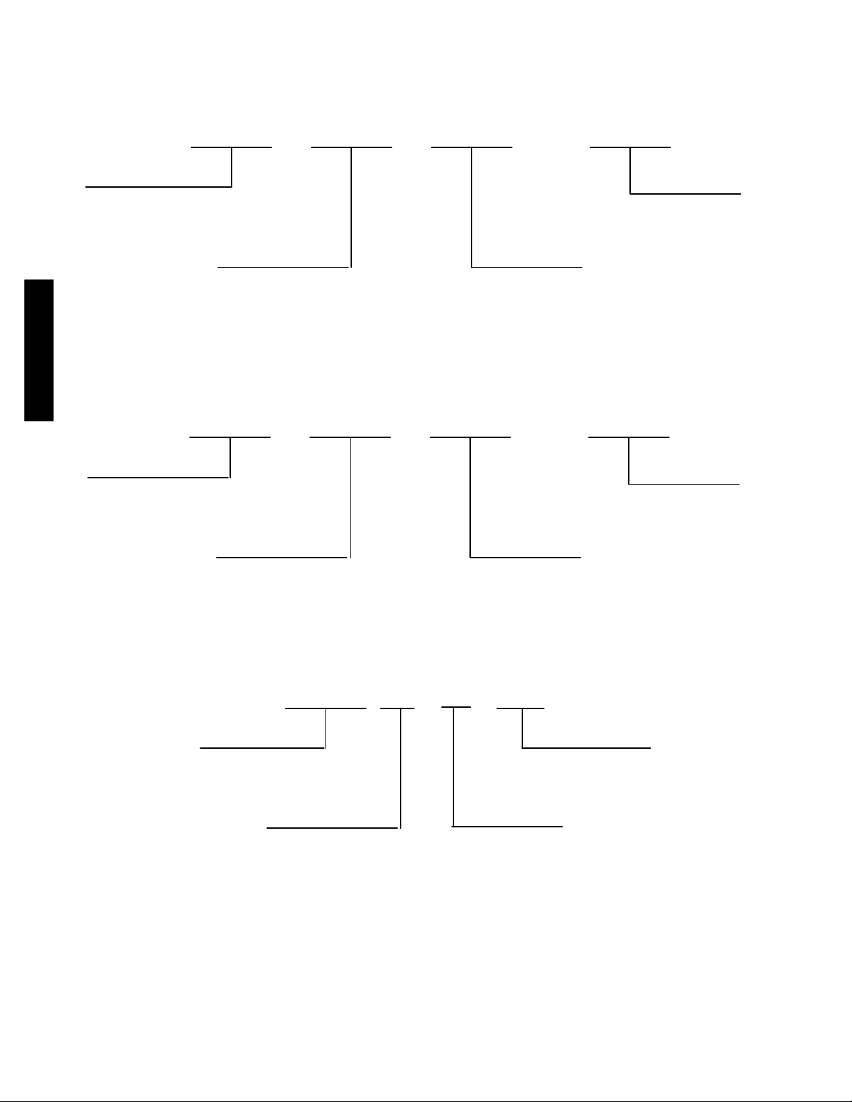
MODEL NUMBER NOMENCLATURE
INDOOR UNIT
40 MVC 3--- 01
Fan Coil Unit
Unit Type
MVC --- Co o l i n g On l y
MVQ --- H e a t Pu m p
018
Nominal Capacity
009 --- 3 / 4 To n
012 --- 1 To n
018 --- 1 --- 1 / 2 To n
024 --- 2 To n s
---
Volt age
--- --- 3 0 V D C
1 --- 1 1 5 --- 1 --- 6 0
3 --- 208/230 ---1 ---60
38/40MVC, MVQ
A i r --- C o o l e d C o n d e n s e r
OUTDOOR UNIT
38 MVC 3--- 01
Unit Type
MVC --- Co o l i n g On l y
MVQ --- H e a t Pu m p
018
Nominal Capacity
009 --- 3 / 4 To n
012 --- 1 To n
018 --- 1 --- 1 / 2 To n
024 --- 2 To n s
---
SERIAL NUMBER NOMENCLATURE
Week of Manufacture
01 06
V
00001
Serial Number
Volt age
1--- 11 5 --- 1 --- 6 0
3--- 208/230 --- 1 ---60
Year of Manufacture
Manufacturing Site
2
STANDARD FEATURES AND ACCESSORIES
Ease Of Installation
Mounting Brackets S
Low Voltage Controls S
Comfort Features
Microprocessor Controls S
Wireless Remote Control S
Automatic Air Sweep S
Air Direction Control S
Auto Restart Function S
Cold Blow Protection On Heat Pumps S
Turbo M o d e O n Si z e s 9K a n d 1 2 K S
Auto Changeover On Heat Pumps S
Energy Saving Features
Sleep Mode S
Stop/Start Timer S
Safety And Reliability
3MinuteTimeDelayForCompressor S
Over Current Protection For Compressor S
Indoor Coil Freeze Protection S
Indoor Coil High Temperature Protection On Heat Pumps S
Condenser High Temperature Protection On heat Pumps{ S
Accumulator On Heat Pumps S
Ease Of Service And Maintenance
Cleanable Filters S
Diagnostics S
Liquid Line Pressure Taps S
Suction And Discharge Pressure Taps (Sizes 18 and 24K) S
Application Flexibility
Low Ambient Controls ( --- 20˚F) A
Condensate Pumps A
Crankcase Heater A
Wind Baffles F
Warranty
5 --- Year Compressor Warranty S
1 --- Parts Warranty S
Compressor Extended Warranty Years 6 Thru 10 O
All Parts And Labor Years 2 Thru 5 O
All Parts And Labor Years 2 Thru 5, Compressor Years 6
Thru 10
{ Sizes 18k & 24k
Legend
SStandard
A Accessory
OOptional
F Field Fabricated
O
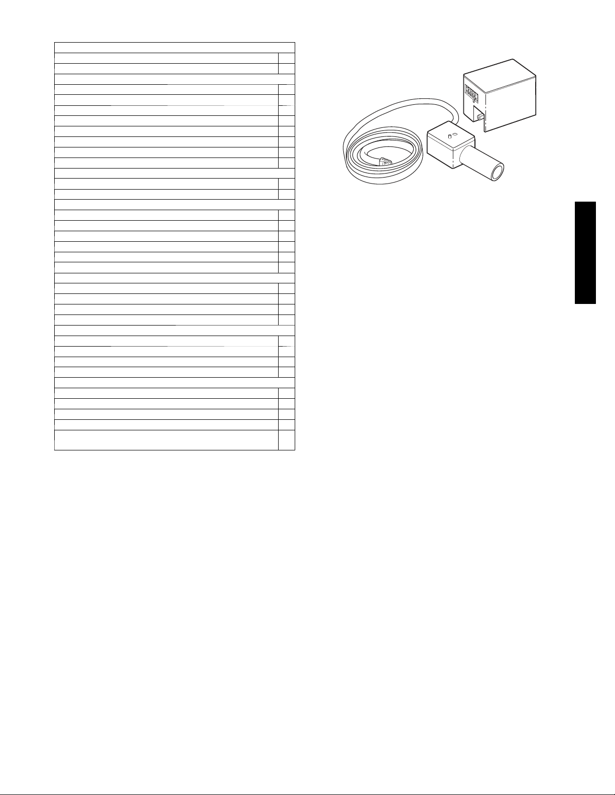
INDOOR UNITS
On high wall fan coils, the condensate pump has a lift capability of
18 ft (5.5 m) or the discharge side with the pump mounted in the
fan coil or 6 ft (1.8 m) on the suction side if the pump must be
remote mounted. The pump mounts inside the unit with quick
plug--in connections, and is recommended when adequate drain
line pitch cannot be provided, or when the condensate must move
up to exit.
NOTE: An external 115v power source will be required to run the
pump on unit sizes 9k and 12k.
OUTDOOR UNITS
LOW AMBIENT KIT
The kit controls condenser fan cycling using a pressure switch. It is
specifically designed to control fan--motor cycles in response to
saturated condensing pressure. This device maintains a constant
saturated condensing temperature of 100 _F ± 10 _F (37.78_C ±
--12.22 _C) at outdoor--air temperatures between 55 _F and --20 _F
(12.78_C ± --12.22_C), and can be used on all outdoor units
without changing the outdoor fan motor.
CRANKCASE HEATER
Available for units with rotary compressors. Heater clamps around
compressor oil sump. Recommended for low-- ambient applications
on sizes 9, 12 , 18, 24 and long line applications.
A07892
Fig. 1 – Condensate Pump
38/40MVC, MVQ
3
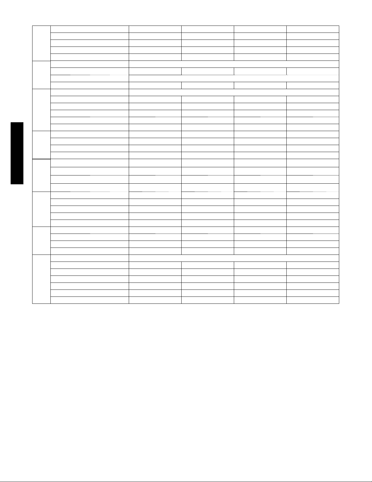
SPECIFICATIONS -- COOLING ONLY UNITS
System Model Number 5 3 M V C 0 0 9 --- --- --- 1 5 3 M V C 0 1 2 --- --- --- 1 5 3 M V C 0 1 2 --- --- --- 3 5 3 M V C 0 1 8 --- --- --- 3
System Voltage 115 V 115 V 208/230 208/230
Control Voltage 0 --- 1 2 P u l s e D C 0 --- 1 2 P u l s e D C 0 --- 1 2 P u l s e D C Pulse DC
Capacity (Btuh) 9000 12000 12000 18000
System
SEER 13.0 13.0 13.0 13.0
Refrigerant Typ e R--- 410A
Design Pressure (PSIG) 550 550 550 550
Metering Device Capillary Tube in Outdoor Unit
Charge (lb) 2.3 2.9 3.0 4.4
Refrigerant
Type Rotary
Model EA82X1C --- 1FZDU1 EA108X1C--- 1FZDU1 PA108X1C--- 3FZDU PA150X2C S--- 3KUU
O i l C h a r g e ( P O E --- o z ) 11.8 11.8 11.8 25.4
Capacitor 45µF/250VAC 45µF/250VAC 35µF/370VAC 40µF/370VAC
Rated Current (RLA) 7.5 9.9 5.2 7.3
Compressor
Locked Rotor Amp (LRA) 40 47 21 32.6
Rpm/CFM 900/1060 900/1090 900/1120 840/1470
Diameter (in) .. No. of Blades 15.8 … 3 15.8 … 3 15.8 … 3 18.1 … 3
Motor (hp) 0.102 0.102 0.102 0.224
Motor
Outdoor
Capacitor 6.5µF/260VAC 6.5µF/260VAC 2.5µF/450VAC 3µF/450VAC
Face A rea (sq. f t) 4.05 3.94 3.94 5.51
38/40MVC, MVQ
No. Rows 2 2 2 4
Fins per inch 17 17 17 18
Circuits 4 4 4 4
Outdoor Coil
Motor Watts/HP 20/.034 20/.034 20/.034 25/.044
Rpm/Cfm (High) 1250/325 1270/425 1270/425 1070/630
Rpm/Cfm (Medium) 1000/260 1100/365 1100/365 1000/570
Rpm/Cfm (Low) 800/190 1000/340 1000/340 960/500
Indoor Motor
Blower Diameter … Length (in) 3.84 … 25.87 4.17 … 25.2 4.17 … 25.2 4.21 … 37.6
Face A rea (sq. f t) 2.15 2.54 2.54 4.36
No. Rows 2 2 2 2
Coil
Fins per inch 19.5 19.5 19.5 19.5
Indoor
Circuits 2 3 3 6
Connection Type Flare
Liquid (Mix Phase) (in) OD 1/4” 1/4” 1/4” 1/4”
Vapor Line (in) OD 3/8” 1/2” 1/2” 1/2”
Condensate Drain (in) .65 (OD) .53 (ID) .65 (OD) .53 (ID) .65 (OD) .53 (ID) .65 (OD) .53 (ID)
Lines
Maximum Length (ft) 65 65 65 100
Refrigerant
Max Lift (Fan Coil Above) (ft) 35 35 35 50
Max Drop (Fan Coil Below) (ft) 35 35 35 50
4
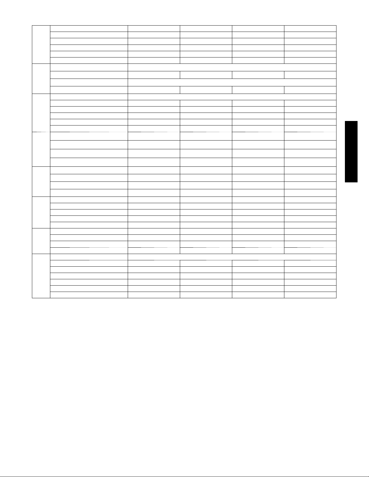
SPECIFICATIONS -- HEAT PUMP UNITS
System Model Number 5 3 M V Q 0 0 9 --- --- --- 1 5 3 M V Q 0 1 2 --- --- --- 1 5 3 M V Q 0 1 2 --- --- --- 3 5 3 M V Q 0 1 8 --- --- --- 3
System Voltage 115 V 115 V 208/230 208/230
Control Voltage 0 --- 1 2 P u l s e D C 0 --- 1 2 P u l s e D C 0 --- 1 2 P u l s e D C Pulse DC
Capacity (Btuh) 9000 12000 12000 18000
System
SEER 13.0 13.0 13.0 13.0
HSPF 7.7 7.7 7.7 7.7
Refrigerant Typ e R--- 410A
Design Pressure (PSIG) 550 550 550 550
Metering Device Capillary Tubes in Outdoor Unit
Charge (lb) 2.35 3.0 3.0
Refrigerant
Type Rotary
Model EA82X1C --- 1FZDU1 EA108X1C--- 1FZDU1 PA108X1C--- 3FZDU PA150X2C S--- 3KUU
O i l C h a r g e ( P O E --- o z ) 11.8 11.8 11.8 25.4
Capacitor 45µF/250VAC 45µF/250VAC 35µF/370VAC 40µF/370VAC
Rated Current (RLA) 7.5 9.9 5.2 7.3
Compressor
Locked Rotor Amp (LRA) 40 47 21 32.6
Rpm/CFM 900/1060 900/1090 900/1120 840/1470
Diameter (in) .. No. of Blades 15.8 … 3 15.8 … 3 15.8 … 3 18.1 … 3
Motor (hp) 0.102 0.102 0.102 0.224
Capacitor 6.5µF/260VAC 6.5µF/260VAC 2.5µF/450VAC 3µF/450VAC
Outdoor Motor
Face A rea (sq. f t) 4.05 3.94 3.94 5.51
No. Rows 2 2 2 4
Fins per inch 17 17 17 18
Circuits 4 4 4 4
Outdoor Coil
Motor Watts/HP 20/.034 20/.034 20/.034 25/.044
Rpm/Cfm (High) 1250/325 1270/425 1270/425 1070/630
Rpm/Cfm (Medium) 1000/260 1100/365 1100/365 1000/570
Motor
Indoor
Rpm/Cfm (Low) 800/190 1000/340 1000/340 960/500
Blower Diameter … Length (in) 3.84 … 25.87 4.17 … 25.2 4.17 … 25.2 4.21 … 37.6
Face A rea (sq. f t) 2.15 2.54 2.54 4.36
No. Rows 2 2 2 2
Coil
Fins per inch 19.5 19.5 19.5 19.5
Indoor
Circuits 2 3 3 6
Connection Type Flare
Liquid (Mix Phase) (in) OD 1/4” 1/4” 1/4” 1/4”
Vapor Line (in) OD 3/8” 1/2” 1/2” 1/2”
Condensate Drain (in) .65 (OD) .53 (ID) .65 (OD) .53 (ID) .65 (OD) .53 (ID) .65 (OD) .53 (ID)
Maximum Length (ft) 65 65 65 100
Lines
Refrigerant
Max Lift (Fan Coil Above) (ft) 35 35 35 50
Max Drop (Fan Coil Below) (ft) 35 35 35 50
38/40MVC, MVQ
5
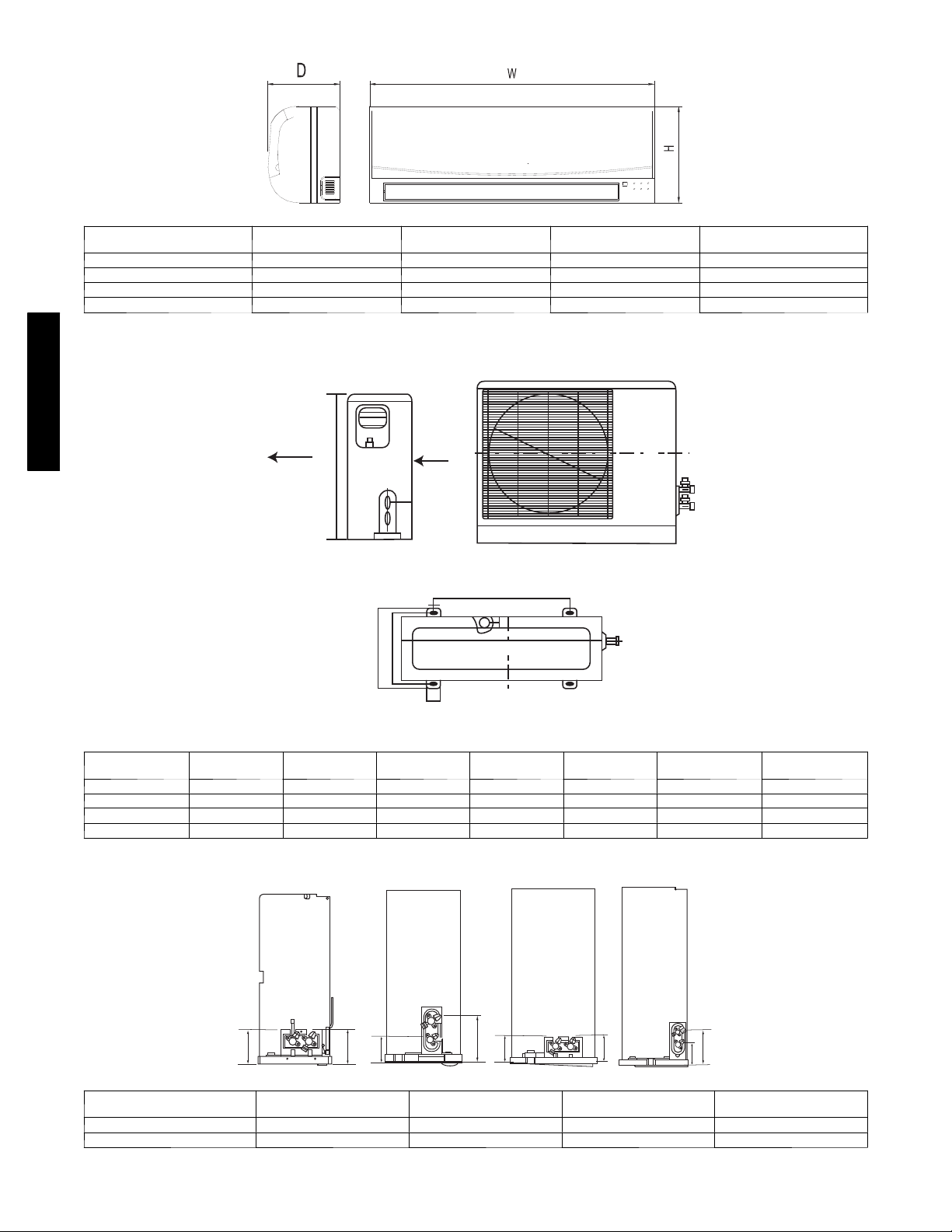
DIMENSIONS -- INDOOR
Model Size
9K 32.09 (815) 11.02 (280) 7.68 (195)
12K 35.67 ( 906) 11.26 (286) 9.25 (235)
18K 49.21 (1250) 12.80 (325) 9.06 (230)
24K 49.21 (1250) 12.80 (325) 9.06 (230)
in. (mm)
DIMENSIONS -- OUTDOOR
A07336
W
H
in. (mm)
D
in. (mm)
Weight lb (kg)
24.2 (11)
33.0 (15)
55.0 (25)
55.0 (25)
38/40MVC, MVQ
Model Size
9K 30.71 (780) 21.26 (540) 21.61 ( 549) 11.81 (300) 10.87 (276)
12K 29.92 (760) 23.23 (590) 20.87 (530) 12.40 (315) 11.42 (290)
18K 33.07 (840) 27.36 (695) 22.05 (560) 14.17 (360) 13.19 (335)
24K 31.16 (893) 33.86 (860) 23.11 (588) 13.98 (355) 13.11 (333)
Air Flow
W
in. (mm)
SERVICE VALVE LOCATI ONS
9K
H
H
in. (mm)
L2
L3
in. (mm)
12K
L1
W
L1
35
A07337
L2
in. (mm)
18K
L3
in. (mm)
24K
Weight lb (kg)
Cooling Only
77.0 (35) 79.2 (36)
85.8 (39) 90.2 (41)
125.4 (57) 125.4 (57)
159.5 (72) 160.6 (73)
Weight lb (kg)
Heat Pumps
Service Valve Locations
J 3.46 (88) 3.19 (81) 3.46 (88) 4.02 (102)
K 3.46 (88) 5.63 (143) 3.62 (92) 6.57 (167)
K
12K
in. (mm)
J
K
18K
in. (mm)
K
J
A07376a
24K
in. (mm)
J
9K
in. (mm)
J
K
6
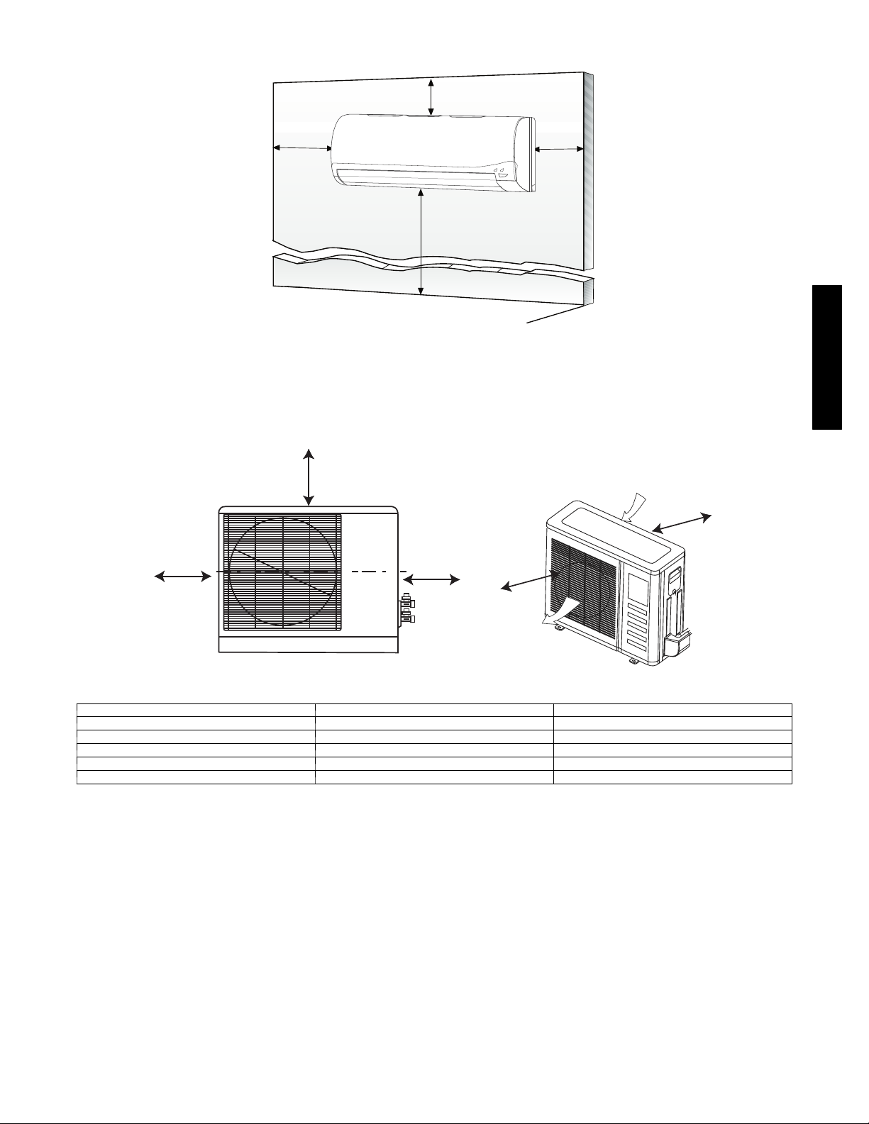
CLEARANCES -- INDOOR
5
"
(0.13m)
min.
6" (0.15m) min.
(1.8m)
6'
Fig. 2 – Indoor unit clearance
5
"
(0.13m)
min.
A07891
CLEARANCES -- OUTDOOR
D
UNIT 9k and 12k in. (mm)
A 24 (610)
B 24 (610)
C 24 (610)
D 4 (102)
E 12 (305)
A
B
Fig. 3 – Outdoor Unit Clearance
38/40MVC, MVQ
Air-inlet
E
C
Air-outlet
A07894
18k and 24k in. (mm)
24 (610)
36 (914)
24 (610)
12 (305)
12 (305)
7
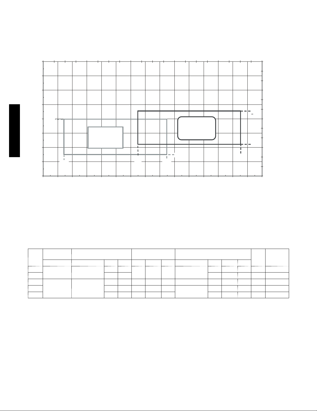
SYSTEM OPERATING ENVELOPE
53MVC/MVQ System Operating Envelope Chart
40
50
60
70
80
90
100
110
120
-10 0 10 20 30 40 50 60 70 80 90 100 110 120 130 140
Outdoor Temperature (ºF)
Indoor Temperature (ºF)
0
5
10
15
20
25
30
35
40
45
50
55
60
-40-35-30-25-20-15-10-5 0 5 1015202530354045505560
Outdoor Temperature (ºC)
Indoor Temperature (ºC)
Cooling
Continuous
Operation
Heating
Continuous
Operation
85º
62ºF
55º
75ºF
55ºF
5ºF
80ºF
125º
38/40MVC, MVQ
Use low ambient control if the unit will operate in cooling at ambient conditions below 55_F (12.78_C).
Fig. 4 – System Operating Enevelope
ELECTRICAL DATA
OPERATING
UNIT
SIZE
*Permissible limits of the voltage range at which the unit will operate satisfactorily
LEGEND
FLA --- Fu l l L o a d A m p s
LRA --- L o c k e d R o t o r A m p s
MCA - -- Minimum Circuit Amps
RLA ---RatedLoadAmps
VOLTAGE*
MAX/MIN V O L T S --- P H --- H Z RLA LRA FLA HP W VOLTS FLA HP W
009
012 9.9 47 1.18 0.044 25 15 25
012
018 7.3 32.6 0.78 0.224 53
024 9.7 34.8 0.62 0.218 100 0.39 0.112 50 14 25
127/104 1 1 5 --- 1 --- 6 0
253/187 208/230---1 ---60
COMPRESSOR OUTDOOR FAN INDOOR FAN
7.5 40
5.2 21 0.38 0.116 36 35 DC 1.18 0.044 25 9 15
0.60 0.102 23 35 DC
208/230---1---60
1.1 0.034 20 12 20
0.26 0.075 31 11 20
A08180
MCA
MAX
FUSE/CB
AMP
8
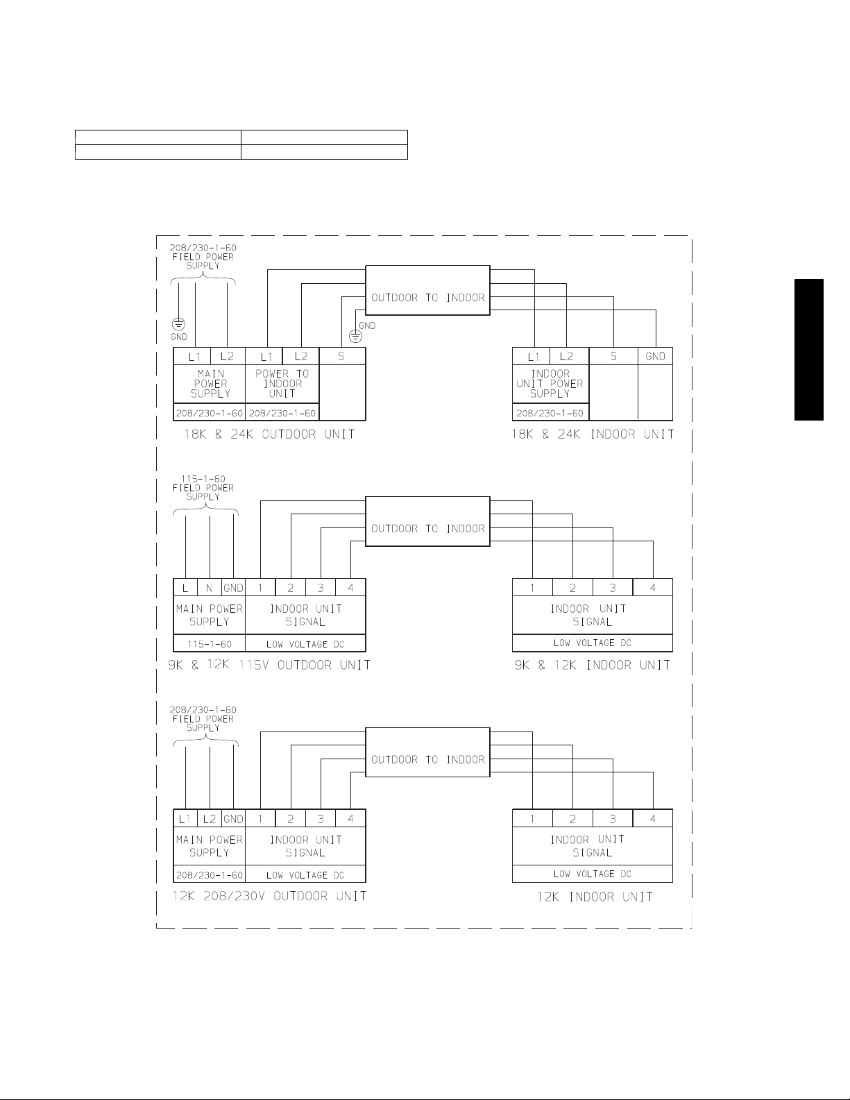
WIRING
The main power is supplied to the outdoor unit. The field supplied connecting cable from the outdoor unit to indoor unit consists of four
wires and provides the power for the indoor unit as well as the communication signal between the outdoor unit and indoor unit.
Voltage drop on the connecting cable should be kept to a minimum. Use cable size and max length below:
18 AWG 50 ft. (16 m)
16 AWG 100 ft. (33 m)
CONNECTION DIAGRAMS
CONNECTING CABLE
CONTROL
CONNECTING CABLE
CONNECTING CABLE
CONTROL
38/40MVC, MVQ
Notes:
1. Do not use thermostat wire for any connection between indoor and outdoor units.
2. All connections between indoor and outdoor units must be as shown. The connections are sensitive to polarity.
3. On the 18k and 24k units, the “S” terminal “CONTROL” output is pulse DC with a potential AC voltage shock hazard.
Fig. 5 – Connection Diagrams
9
A07654
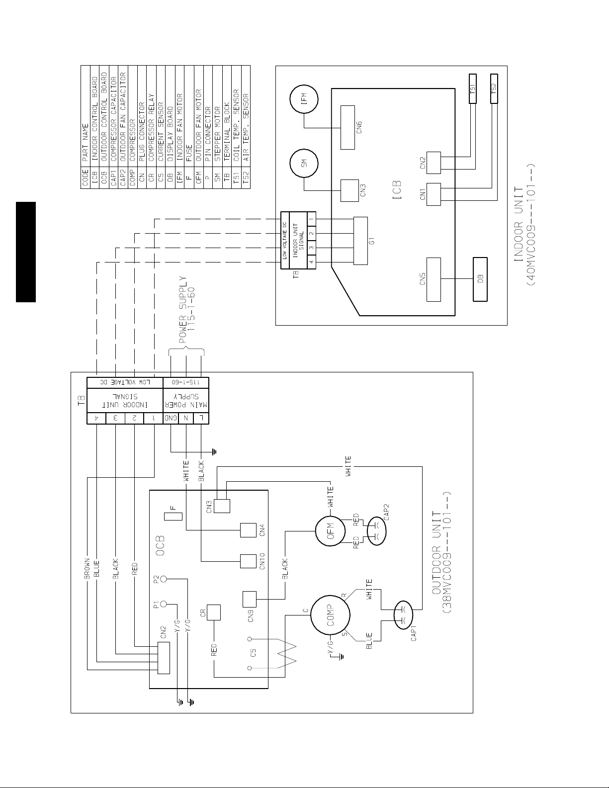
38/40MVC, MVQ
Fig. 6 – Wiring Diagram 38MVC009------ 1 W/ 40MVC009-- -- --1
WIRING DIAGRAMS
10
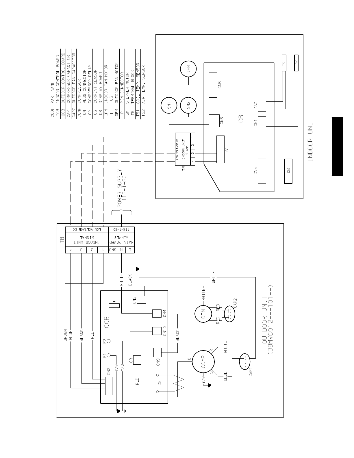
38/40MVC, MVQ
Fig. 7 – Wiring Diagram 38MVC012------ 1 W/ 40MVC012-- -- --1
WIRING DIAGRAMS (CONT.)
11
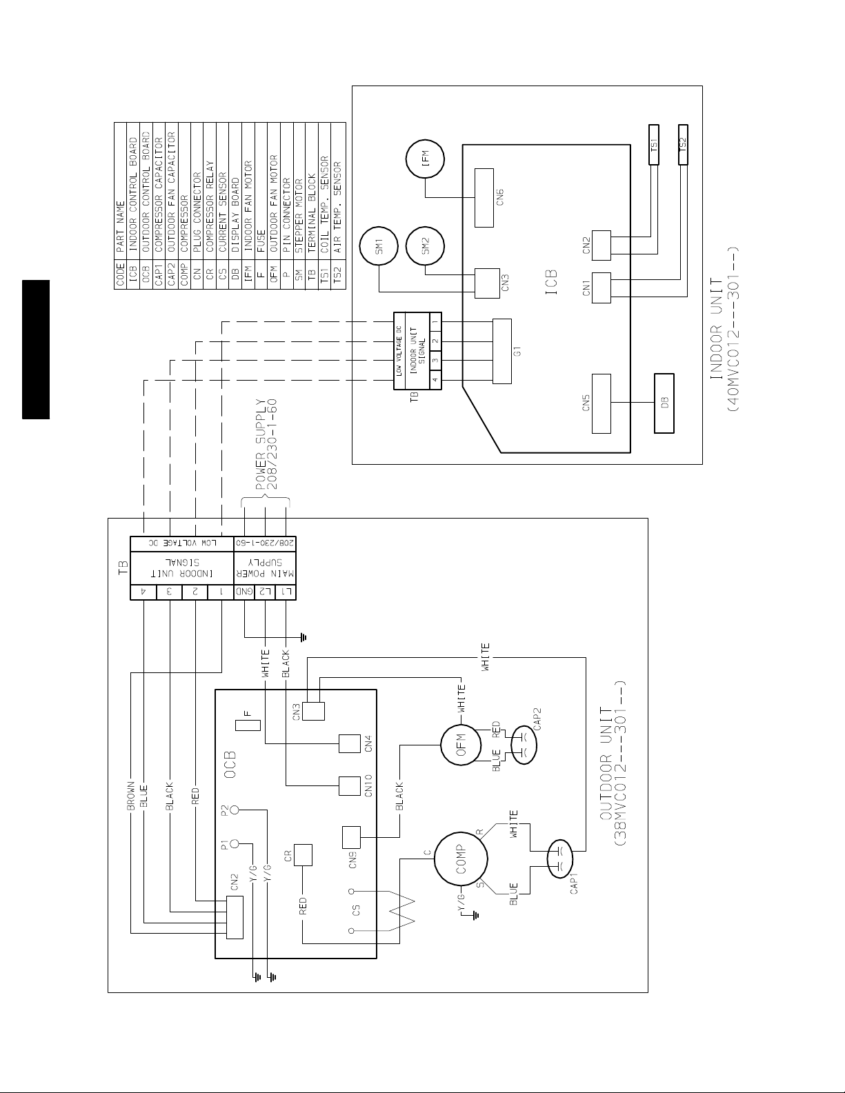
38/40MVC, MVQ
Fig. 8 – Wiring Diagram 38MVC012------ 3 W/ 40MVC012-- -- --3
WIRING DIAGRAMS (CONT.)
12
38/40MVC, MVQ
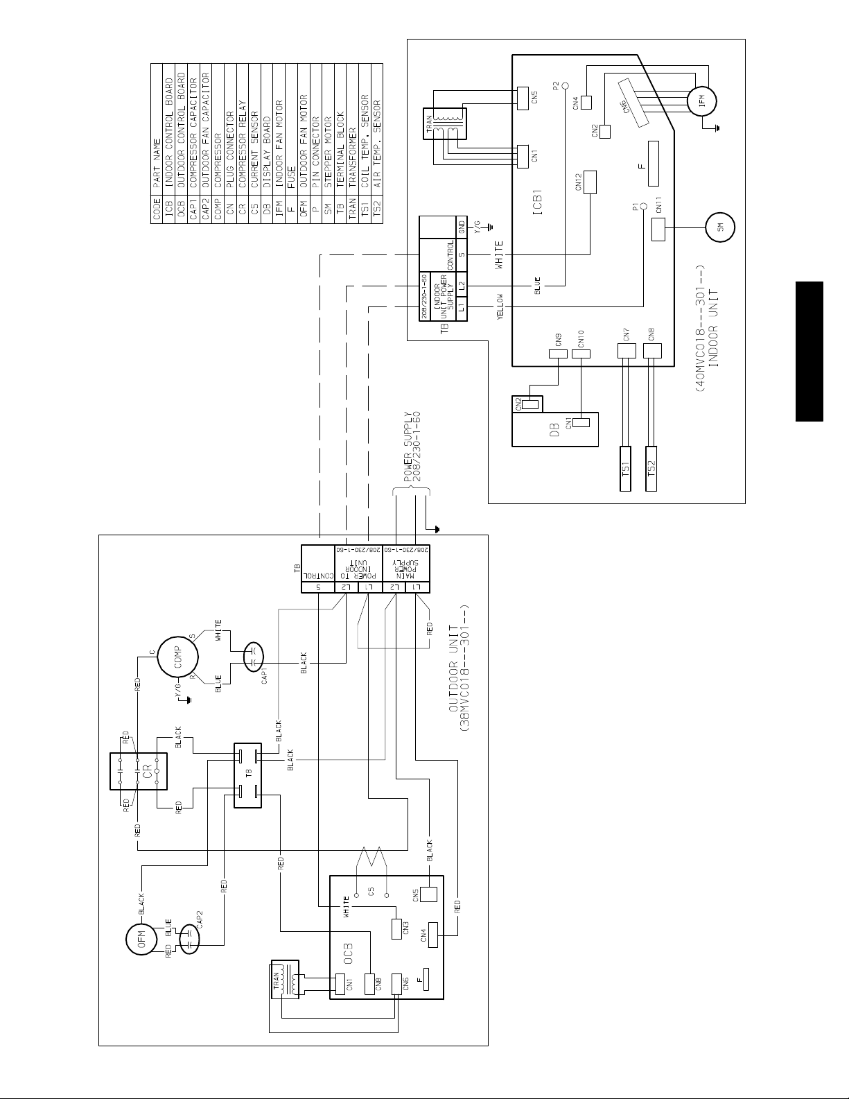
Fig. 9 – Wiring Diagram 38MVC018------ 3 W/ 40MVC018-- -- --3
WIRING DIAGRAMS (CONT.)
13
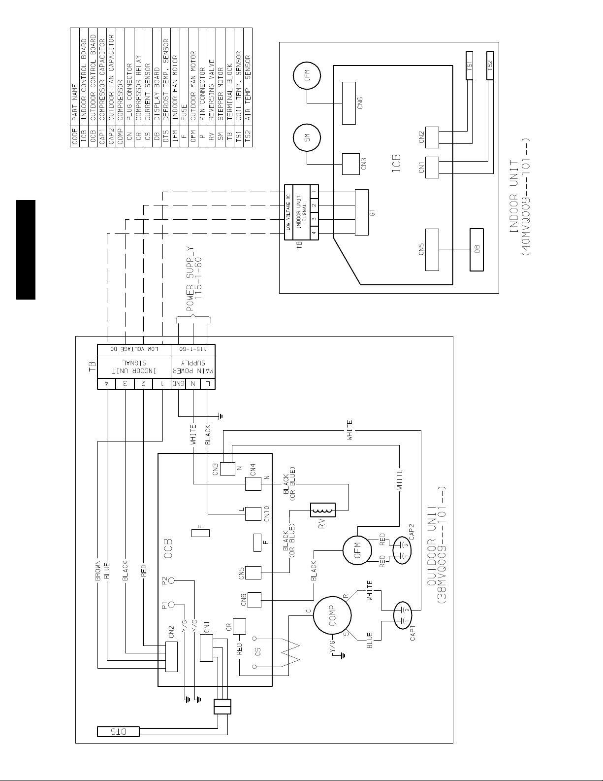
38/40MVC, MVQ
Fig. 10 – Wiring Diagram 38MVQ009------ 1 W/ 40MVQ009-- -- --1
WIRING DIAGRAMS (CONT.)
14