

Carrier 40MBCQ123 Installation Manual
40MB*C
Cassette Ductless System
Sizes 09 to 18
Installation Instructions
TABLE OF CONTENTS
PAGE
SAFETY CONSIDERATIONS 2.........................
PARTS LIST 3.......................................
SYSTEM REQUIREMENTS 4...........................
DIMENSIONS − INDOOR 5............................
CLEARANCES − INDOOR 6...........................
INSTALLATION TIPS 7................................
INDOOR UNIT INSTALLATION 7.......................
ELECTRICAL DATA 13...............................
CONNECTION DIAGRAMS 13.........................
START−UP 15........................................
TROUBLESHOOTING 16..............................
NOTE: The images in this manual are for illustration purposes
only. The actual model may differ slightly.
NOTE: Read the entire instruction manual before starting the
installation.
SAFETY CONSIDERATIONS
Installing, starting up, and servicing air−conditioning equipment
can be hazardous due to system pressures, electrical components,
and equipment location (roofs, elevated structures, etc.).
Only trained, qualified installers and service mechanics should
install, start−up, and service this equipment.
Untrained personnel can perform basic maintenance functions such
as cleaning coils. All other operations should only be performed by
trained service personnel.
When working on the equipment, observe precautions in the
literature and on tags, stickers, and labels attached to the
equipment.
Follow all safety codes. Wear safety glasses and work gloves. Keep
a quenching cloth and fire extinguisher nearby when brazing. Use
care in handling, rigging, and setting bulky equipment.
Read these instructions thoroughly and follow all warnings or
cautions included in the literature and attached to the unit. Consult
the local building codes and National Electrical Code (NEC) for
special requirements. Recognize safety information.
!
!
This is the safety−alert symbol
the unit and in instructions or manuals, be alert to the potential for
personal injury. Understand these signal words: DANGER,
WARNING, and CAUTION. These words are used with the
safety−alert symbol. DANGER identifies the most serious hazards
which will result in severe personal injury or death. WARNING
signifies hazards which could result in personal injury or death.
CAUTION is used to identify unsafe practices which may result in
minor personal injury or product and property damage. NOTE is
used to highlight suggestions which will result in enhanced
installation, reliability, or operation.
. When you see this symbol on
!
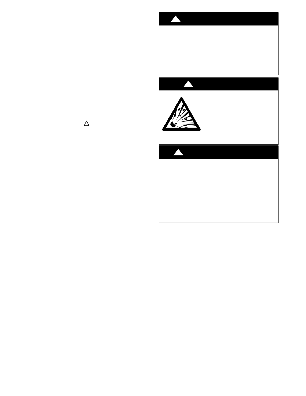
ELECTRICAL SHOCK HAZARD
Failure to follow this warning could result in personal
injury or death.
Before installing, modifying, or servicing system, the
main electrical disconnect switch must be in the OFF
position. There may be more than 1 disconnect switch.
Lock out and tag switch with a suitable warning label.
!
EQUIPMENT DAMAGE HAZARD
Failure to follow this caution may result in equipment
damage or improper operation.
Do not bury more than 36 in. (914 mm) of refrigerant pipe
in the ground. If any section of pipe is buried, there must be
a 6 in. (152 mm) vertical rise to the valve connections on
the outdoor units. If more than the recommended length is
buried, refrigerant may migrate to the cooler buried section
during extended periods of system shutdown. This causes
refrigerant slugging and could possibly damage the
compressor at start−up.
WARNING
!
WARNING
EXPLOSION HAZARD
Failure to follow this warning could
result in death, serious personal injury,
and/or property damage.
Never use air or gases containing
oxygen for leak testing or operating
refrigerant compressors. Pressurized
mixtures of air or gases containing
oxygen can lead to an explosion.
CAUTION
2
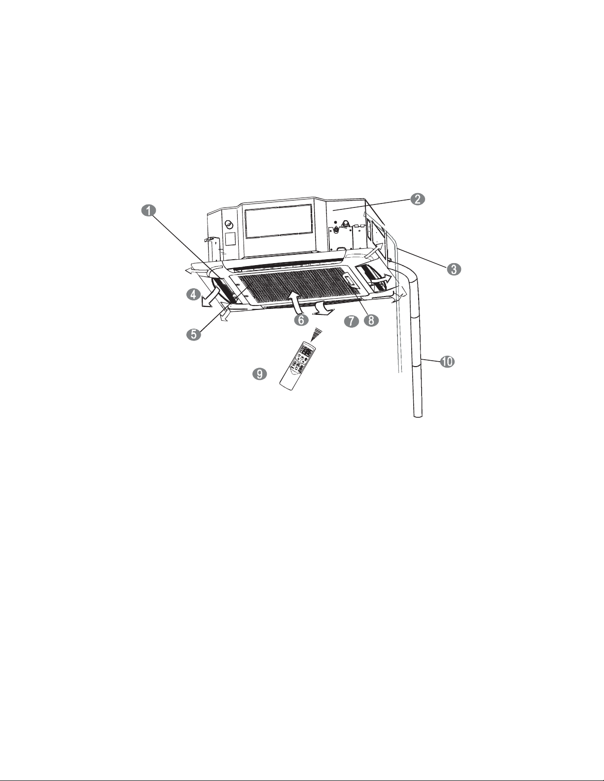
PARTS LIST
Table 1—Parts List
PART NO. PART NAME
1 Air flow louver (at air outlet)
2 Drain pump (drain water from the indoor unit)
3 Drain pipe (Field Supplied)
4 Air outlet
5 Air filter (inside grille/ceiling panel)
6 Air inlet
7 Grille/Ceiling panel (Required - sold separately)
8 Display panel
9 Remote controller
10 Refrigerant pipe (Field Supplied)
Fig. 1 - Parts List
Note:
- If the outdoor unit is higher than the indoor unit, prevent rain from flowing into the indoor unit, along the connection pipe, by creating a downward arc
in the connection pipe before it enters the wall to the indoor unit. This ensures that rain drips from the connection pipe before entering the wall.
- Piping and the interconnecting wiring are field supplied.
- Fig.1 is only a sketch. Different models may differ slightly.
See Table 2 for the units covered in these installation instructions.
Table 2—Indoor Units
kBTUh V-Ph-Hz ID Model No.
9 208/230-1-60 40MBQB09C--3
12 208/230-1-60 40MBQB12C--3
18 208/230-1-60 40MBQB18C--3
3
SYSTEM REQUIREMENTS
Allow sufficient space for airflow and unit servicing. See Fig. 3 for the minimum required distances between the unit and the walls or ceilings.
PIPING
IMPORTANT: Both refrigerant lines must be insulated separately.
S Minimum refrigerant line length between the indoor and outdoor units is 10 ft. (3 m).
S Table 3 lists the pipe sizes for the indoor unit. Refer to the outdoor unit installation instructions for other allowed piping lengths and
refrigerant information.
Table 3—Indoor Unit Pipe Sizes
SYSTEM SIZE 9K 12K 18K
Piping
Gas Pipe (size - connection type) In (mm) 3/8 (9.52) 1/2 (12.7) 1/2 (12.7)
Liquid Pipe (size - connection type) In (mm) 1/4 (6.35) 1/4 (6.35) 1/4 (6.35)
WIRING
All wires must be sized per NEC (National Electrical Code) or
CEC (Canadian Electrical Code) and local codes. Use the
Electrical Data table MCA (minimum circuit amps) and MOCP
(maximum over current protection) to correctly size the wires and
the disconnect fuse or breakers respectively.
Per the caution note, only stranded copper conductors with a 600
volt rating and double insulated copper wire must be used. The
use of BX cable is not recommended.
IMPORTANT: The use of BX cable is not recommended.
Recommended Connection Method for Power and
Communication Wiring − Power and Communication Wiring:
The main power is supplied to the outdoor unit. The field
supplied 14/3 power/communication wiring from the outdoor unit
to the indoor unit consists of four (4) wires and provides the
power for the indoor unit. Two wires are high voltage AC power.
One wire is communication wiring and the other is a ground wire.
Recommended Connection Method for Power and
Communication Wiring (To minimize communication wiring
interference)
Power Wiring:
The main power is supplied to the outdoor unit. The field
supplied connecting cable from the outdoor unit to the indoor unit
consists of three (3) wires and provides the power for the indoor
unit. Two wires are high voltage AC power and one is a ground
wire.
Communication Wiring:
A separate shielded stranded copper conductor only, with a 600
volt rating and double insulated copper wire, must be used as the
communication wire from the outdoor unit to the indoor unit.
Please use a separate shielded 16GA stranded control wire.
!
EQUIPMENT DAMAGE HAZARD
Failure to follow this caution may result in equipment
damage or improper operation.
S Wires should be sized based on NEC and local codes.
S Use copper conductors only with a 600 volt rating and
double insulated copper wire.
CAUTION
4
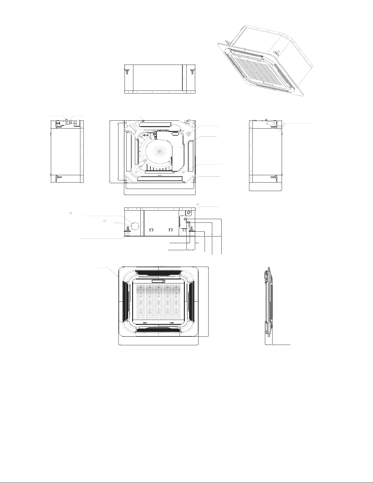
DIMENSIONS − INDOOR
Liquid side
Gas side
)
(
6
5
.
6
5
2
Outside Air Intake
Wiring connection port
Panel
20.59(523)
22.44(570)
5
.
(7
2
5
9
Body
21.46(545)
22.44(570)
)
1.65(42)
2.67(68)
Drain hole
( for Service )
E-parts box
4-Screw hole
(for install panel)
4-install hanger
)
5
(2
.
8
0
9
Drain pipe
1.73(44)
6.18(157)
4.96(126)
Wiring connection port
10.24(260)
25.47(647)
25.47(647)
1.97(50)
Fig. 2 - Indoor Unit
Table 4—Dimensions Indoor
UNIT SIZE
BODY PANEL BODY PANEL BODY PANEL
Height in(mm) 10.24 (260) 1.97 (50) 10.24 (260) 1.97 (50) 10.24 (260) 1.97 (50)
Width in(mm) 22.44 (570) 25.47 (647) 22.44 (570) 25.47 (647) 22.44 (570) 25.47 (647)
Depth in(mm) 22.44 (570) 25.47 (647) 22.44 (570) 25.47 (647) 22.44 (570) 25.47 (647)
Height in(mm) 11.42 (290) 4.84 (123) 11.42 (290) 4.84 (123) 11.42 (290) 4.84 (123)
Width in(mm) 25.79 (655) 28.15 (715) 25.79 (655) 28.15 (715) 25.79 (655) 28.15 (715)
Depth in(mm) 25.79 (655) 28.15 (715) 25.79 (655) 28.15 (715) 25.79 (655) 28.15 (715)
Weight-Gross lbs(kg) 41.88 (19) 9.92 (4.5) 41.88 (19) 9.92 (4.5) 46.3 (21) 9.92 (4.5)
Weight-Net lbs(kg) 35.27 (16) 5.51 (2.5) 35.27 (16) 5.51 (2.5) 39.68 (18) 5.51 (2.5)
9 12 18
DIMENSIONS
PACKING
5
 Loading...