

Page 1
40MAQ
High Wall Ductless Split Sys tem
Sizes 09 to 36
Installation Instructions
NOTE: Read the entire instruction manual before starting the
installation.
TABLE OF CONTENTS
PAGE
SAFETY CONSIDERATIONS 2.........................
PARTS L IST 3.......................................
SYSTEM REQUIREMENTS 4...........................
DIMENSIONS -- INDOOR 5............................
CLEARANCES -- INDOOR 5...........................
INSTALLATION TIPS 6................................
INDOOR UNIT INSTALLATION 6.......................
ELECTRICAL DATA 7................................
CONNECTION DIAGRAMS 7..........................
INSTALL ALL POWER, INTERCONNECTING WIRING,
AND PIPING TO INDOOR UNIT 7......................
WIRELESS REMOTE CONTROL INSTALLATION 8.......
START--UP 9.........................................
TROUBLESHOOTING 10..............................
Page 2
SAFETY CONSIDERATIONS
Installing, starting up, and servicing air-- conditioning equipment
can be hazardous due to system pressures, electrical components,
and equipment location (roofs, elevated structures, etc.).
Only trained, qualified installers and service mechanics should
install, start--up, and service this equipment.
Untrained personnel can perform basic maintenance functions such
as cleaning coils. All other operations should be performed by
trained service personnel.
When working on the equipment, observe precautions in the
literature and on tags, stickers, and labels attached to the
equipment.
Follow all safety codes. Wear safety glasses and work gloves. Keep
quenching cloth and fire extinguisher nearby when brazing. Use
care in handling, rigging, and setting bulky equipment.
Read these instructions thoroughly and follow all warnings or
cautions included in literature and attached to the unit. Consult
local building codes and National Electrical Code (NEC) for
special requirements. Recognize safety information. This is the
!
!
safety--alert symbol
in instructions or manuals, be alert to the potential for personal
injury. Understand these signal words: DANGER, WARNING,
and CAUTION. These words are used with the safety--alert
symbol. DANGER identifies the most serious hazards which will
result in severe personal injury or death. WARNING signifies
hazards which could result in personal injury or death. CAUTION
is used to identify unsafe practices which may result in minor
personal injury or product and property damage. NOTE is used to
highlight suggestions which will result in enhanced installation,
reliability, or operation.
. When you see this symbol on the unit and
!
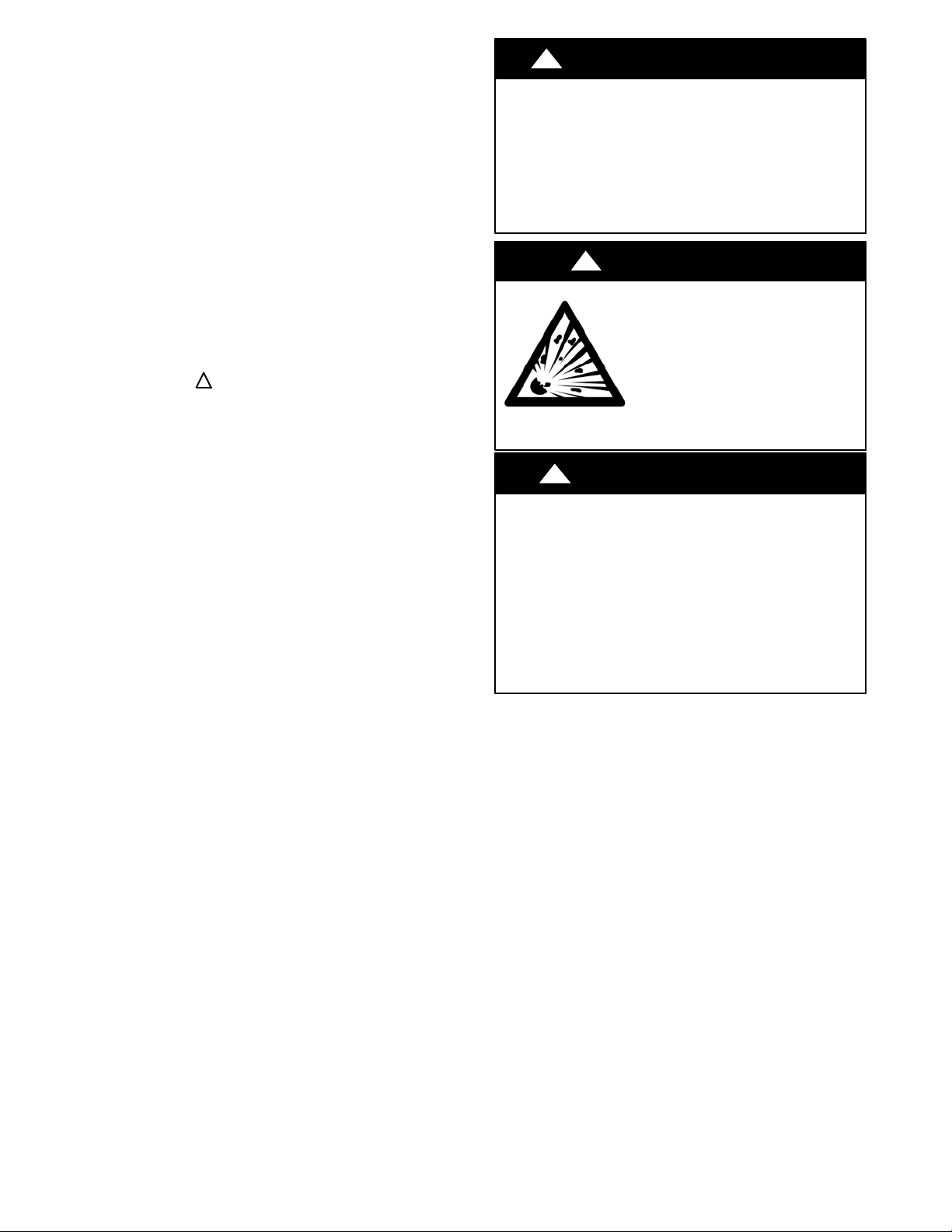
ELECTRICAL SHOCK HAZARD
Failure to follow this warning could result in personal
injury or death.
Before installing, modifying, or servicing system, main
electrical disconnect switch must be in the OFF
position. There may be more than 1 disconnect switch.
Lock out and tag switch with a suitable warning label.
!
EQUIPMENT DAMAGE HAZARD
Failure to follow this caution may result in equipment
damage or improper operation.
Do not bury more than 36 in. (914 mm) of refrigerant pipe
in the ground. If any section of pipe is buried, there must be
a 6 in. (152 mm) vertical rise to the valve connections on
the outdoor units. If more than the recommended length is
buried, refrigerant may migrate to the cooler buried section
during extended periods of system shutdown. This causes
refrigerant slugging and could possibly damage the
compressor at start--up.
WARNING
!
WARNING
EXPLOSION HAZARD
Failure to follow this warning could
result in death, serious personal injury,
and/or property damage.
Never use air or gases containing
oxygen for leak testing or operating
refrigerant compressors. Pressurized
mixtures of air or gases containing
oxygen can lead to an explosion.
CAUTION
2
Page 3
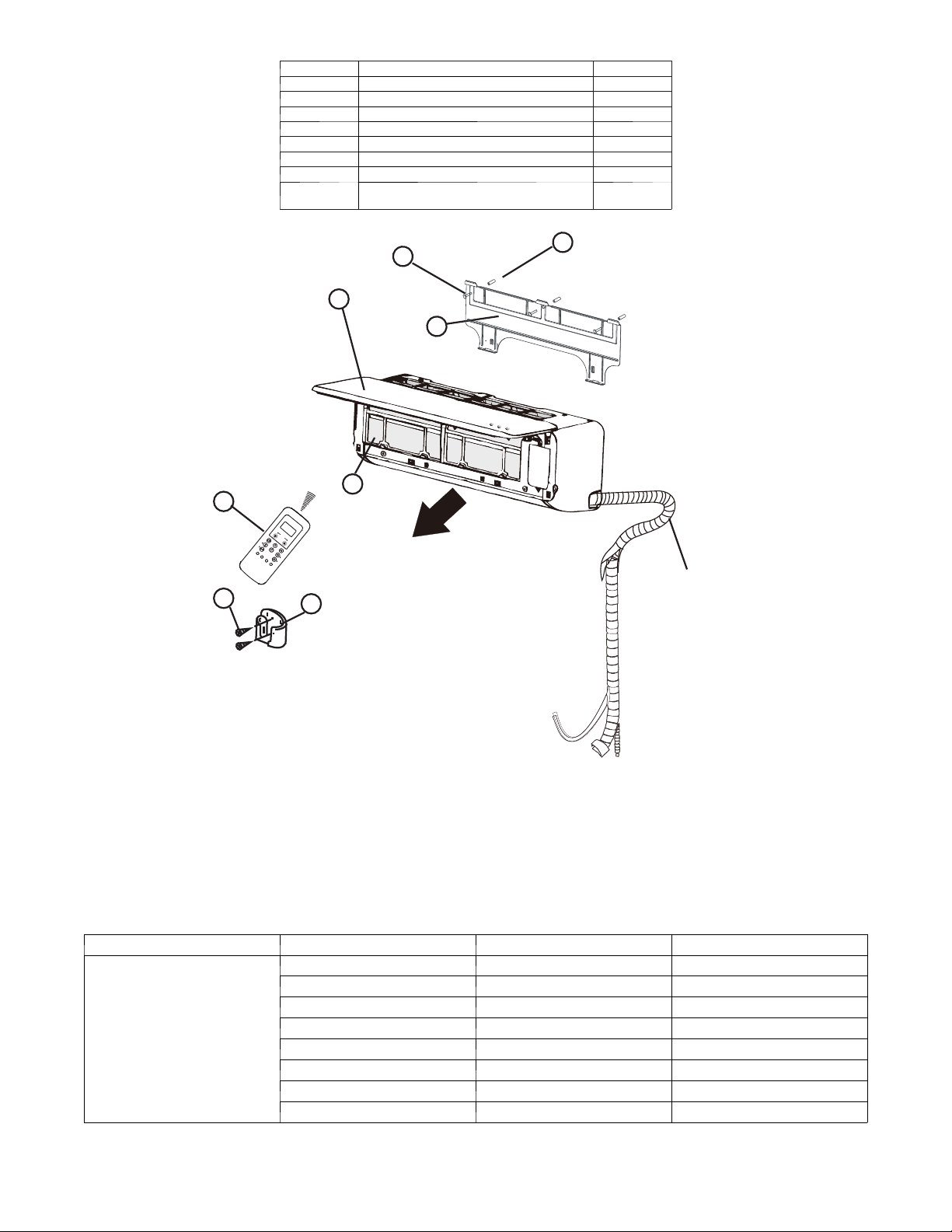
PARTS LIST
Part No. Name of Part Qty
1 Indoor Unit 1
2 Mounting Plate 1
3 M o u nt in g S c r ew A S T3 .9 x2 5 --- C --- H 5
4 Anchor 5
5 Air Filter 1
6 Remote Control 1
7 Remote Control Holder 1
8
Remote Control Mounting Screw B
ST2.0x10 ---C --- H
2
3
4
1
2
5
6
A
U
T
O
C
O
O
D
L
R
Y
H
E
A
T
F
A
N
H
I
G
H
T
M
E
E
D
M
L
P
O
M
W
o
d
e
O
n
S
/
O
w
f
f
i
n
g
F
a
n
S
e
l
f
C
S
l
e
l
e
a
e
n
p
F
ol
I
o
l
n
o
i
w
z
e
M
r
e
S
T
m
L
im
a
E
r
D
e
t
E
r
y
e
T
u
F
r
b
.
o
P
.
S
i
le
n
c
e
8
7
r
Ai
Outlet
Interconnecting
Piping/wiring
Fig. 1 --- Parts List
Note:
--- If the outdoor unit is higher than the indoor unit, prevent rain from flowing into the indoor unit along the connection pipe by making a downward arc in the conne ction pipe before it
enters the wall to the indoor unit. This ensures that rain drips from the connection pipe bef ore it enters the wall.
--- Piping and the interconnecting wiring are field supplied.
--- The illustration above is only a sketch. Different models may be slightly different.
The following units are covered in these installation instructions.
Table 1—Indoor Units
Description
kBTUh V --- P h --- H z ID Model No.
9 1 1 5 --- 1 --- 6 0 40MAQB09B --- ---1
12 1 15 --- 1 --- 6 0 40MAQB12B--- --- 1
9 208/230--- 1--- 60 40MAQB09B --- ---3
High Wall
12 208/230--- 1 --- 60 40MAQB12B --- ---3
18 208/230--- 1 --- 60 40MAQB18B --- ---3
24 208/230--- 1 --- 60 40MAQB24B --- ---3
30 208/230--- 1 --- 60 40MAQB30B --- ---3
36 208/230--- 1 --- 60 40MAQB36B --- ---3
3
A150726
Page 4

SYSTEM REQUIREMENTS
Allow sufficient space for airflow and servicing unit. See Fig. 3 for minimum required distances between unit and walls or ceilings.
Piping
IMPORTANT: Both refrigerant lines must be insulated separately.
S Table 2 lists the pipe sizes for the indoor unit. Refer to the outdoor unit installation instructions for other allowed piping lengths and
refrigerant information.
Table 2—Indoor Unit Pipe Sizes
Gas Pipe
Liquid Pipe
UNIT SIZE
9K
(115V)
in 3/8 1/2 3/8 1/2 1/2 5/8 5/8 5/8
(mm) 9.52 12.7 9.52 12.7 12.7 16 16 16
in 1/4 1/4 1/4 1/4 1/4 3/8 3/8 3/8
(mm) 6.35 6.35 6.35 6.35 6.35 9.52 9.52 9.52
12K
(115V)
9K
(208/230V)
12K
(208/230V)
18K
(208/230V)
24K
(208/230V)
30K
(208/230V)
(208/230V)
36K
Wiring
All wires must be sized per NEC (National Electrical Code) or
CEC (Canadian Electrical Code) and local codes. Use the Electrical
Data table MCA (minimum circuit amps) and MOCP (maximum
over current protection) to correctly size the wires and the
disconnect fuse or breakers respectively.
Per caution note, only stranded copper conductors with a 600 volt
rating and double insulated copper wire must be used. The use of
BX cable is not recommended.
Recommended Connection Method for Power and
Communication Wiring -- Power and Communication Wiring:
The main power is supplied to the outdoor unit. The field supplied
14/3 power/communication wiring from the outdoor unit to the
indoor unit consists of four (4) wires and provides the power for
the indoor unit. Two wires are high voltage AC power, one is
communication wiring and the other is a ground wire.
Recommended Connection Method for Power and
Communication Wiring (To minimize communication wiring
interference) Power Wiring:
The main power is supplied to the outdoor unit. The field supplied
power wiring from the outdoor unit to the indoor unit consists of
three (3) wires and provides the power for the indoor unit. Two
wires are high voltage AC power and one is a ground wire.
To minimize voltage drop, the factory recommended wire size is
14/2 stranded with a ground.
Communication Wiring:
A separate shielded stranded copper conductor only, with a 600
volt rating and double insulated copper wire, must be used as the
communication wire from the outdoor unit to the indoor unit.
Please use a separate shielded 16GA stranded control wire.
!
CAUTION
EQUIPMENT DAMAGE HAZARD
Failure to follow this caution may result in equipment
damage or improper operation.
S Wires should be sized based on NEC and local codes.
S Use copper conductors only with a 600 volt rating and
double insulated copper wire.
4
Page 5

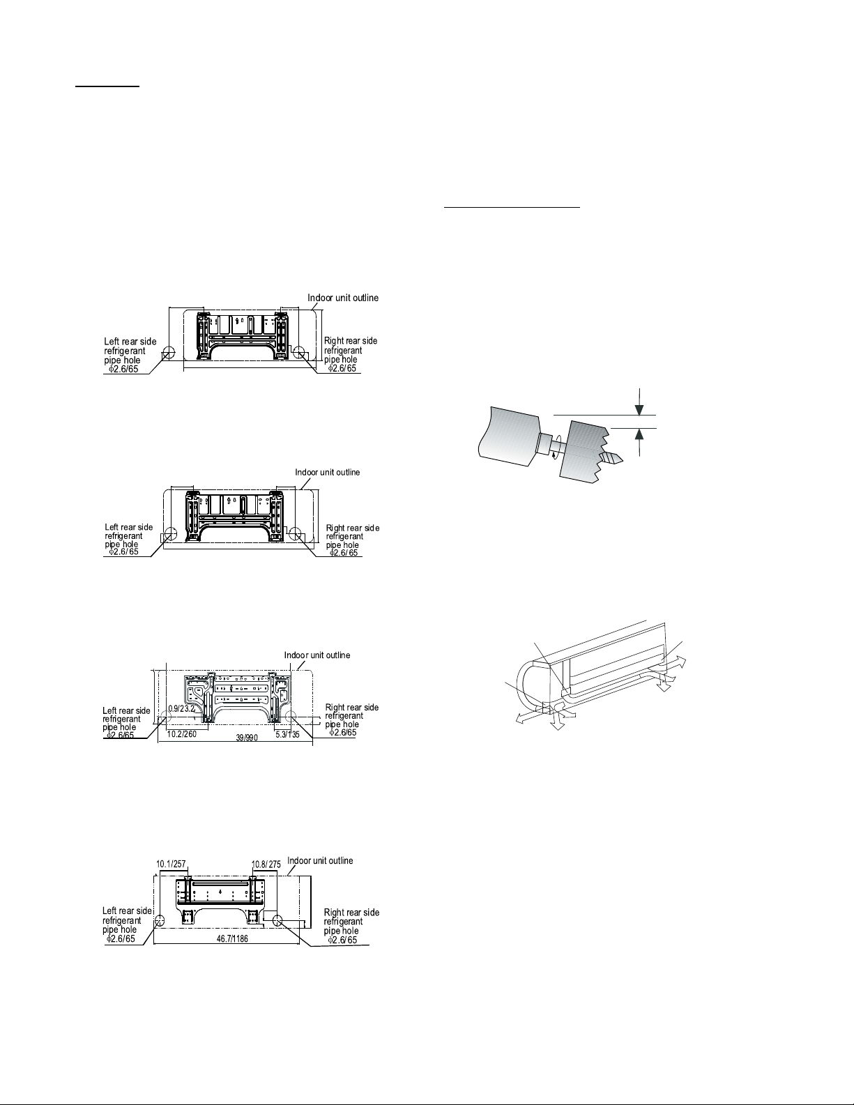
DIMENSIONS -- INDOOR
Fig. 2 --- Indoor Unit Dimensions
Table 3—Indoor Unit Dimensions
HIGH WALL UNIT SIZE 9K 12K 9K 12K 18K 24K 30K 36K
Volt age (115V) (115V) (208/230V) (208/230V) (208/230V) (20/230V) (208/230V) (20/230V)
Height In (mm) 11.02 (280) 11.02 (280) 11.02 (280) 11.02 (280) 12.40 (315) 13.39 (343) 13.39 (343) 13.39 (343)
Width In (mm) 32.87 (835) 32.87 (835) 32.87 (835) 32.87 (835) 38.98 (990) 46.69 (1186) 46.69 (1186) 46.69 (1186)
Depth In (mm) 7.80 (198) 7.80 (198) 7.80 (198) 7.80 (198) 8.58 (218) 10.16 (258) 10.16 (258) 10.16 (258)
W e i g h t --- N e t Lbs (kg) 19.18 (8.7) 19.18 (8.7) 19.18 (8.7) 19.18 (8.7) 24.46 (12.0) 40.12 (18.2) 40.12 (18.2) 40.12 (18.2)
CLEARANCES -- INDOOR
CEILING
A150772
5
"
(0.13m)
min.
6" (0.15m) min.
(1.8m)
6'
FLOOR
Fig. 3 --- Indoor Unit Clearance
5
"
(0.13m)
min.
A07891
5
Page 6
INSTALLATION TIPS
Ideal installation locations include:
Indoor
Unit
S A location where there are no obstacles near inlet and outlet area.
S A location which can bear the weight of indoor unit.
S Do not install indoor units near a direct source of heat such as
direct sunlight or a heating appliance.
S A location which provides appropriate clearances as outlined in
Fig. 3.
INDOOR UNIT INSTALLA TION
INSTALL MOUNTING PLATE
The mounting plate will look like one of the following figures
depending on the model size.
Unit: inch/mm
7.1/180
1.8/45
29.5/750
Sizes 09K & 12K
Fig. 4 --- Mounting Plate -- Model sizes 09, 12
Unit: inch/mm
4.3/110
1.4/36.5
11/280
1.8/45
A150728
2. The mounting plate should be located horizontally and level
on the wall. All minimum spacings shown in Fig. 3 should
be maintained.
3. If the wall is block, brick, concrete or similar material, drill
.2” (5 mm) diameter holes and insert anchors for the
appropriate mounting screws.
4. Attach the mounting plate to the wall.
DRILL HOLE IN WALL FOR INTERCONNECTING
PIPING, DRAIN AND WIRING
Refrigerant Line Routing
The refrigerant lines may be routed in any of the four directions
showninFig.9.
For maximum serviceability, it is recommended to have refrigerant
line flare connections and the drain connections on the outside of
the wall that the fan coil can be mounted on.
If piping is going through the back:
1. Determine the pipe hole position using the mounting plate
as a template. Drill pipe hole diameter per values given in
Fig. 4 through 7. The outside pipe hole is 1/2--in. (13 mm)
min. lower than inside pipe hole, so it slants slightly
downward (see Fig. 8).
1/2 in. (13 mm)
Min.
5.5/140
1.8/45
32.9/835
Size 18K
4.3/110
1.4/36.5
5
11/280
/4
1.8
Fig. 5 --- Mounting Plate -- Model size 18
Unit: inch/mm
12.4/315
Size 24K
Fig. 6 --- Mounting Plate -- Model sizes 24
1.8/45
Unit: inch/mm
A150727
A150729
INDOOR
OUTDOOR
Fig. 8 --- Drill Holes
If piping is going through the right or left side:
1. Use a small saw blade to care fully remove the corresponding
plastic covering on side panel and drill the appropriate size
hole where the pipe is going through the wall.
Pipe cover
Pipe holder
1
2
Right back piping
Pipe cover
4
Left piping
3
Left back piping
Right piping
Fig. 9 --- Piping Locations
A07371
A14349
43
1.8/45
3
13.5/
0.85/21.5
Size 30K & 36K
A150730
Fig. 7 --- Mounting Plate -- Model sizes 30, 36
1. Carefully remove the mounting plate, which is attached to
the back of the indoor unit.
6
Page 7

ELECTRICAL DA TA
k
HIGH WALL UNIT
SIZE
9K
12K 0.33 0.053
9K
12K 0.33 0.053
18K 0.49 0.067
24K 0.61 0.16
30K 0.61 0.16
36K 0.61 0.16
LEGEND
F L A --- F ul l L o a d A mp s
V --- Ph --- Hz FLA HP
1 1 5 --- 1 --- 6 0
208/230--- 1 ---60
CONNECTION DIAGRAMS
Table 4—Electrical Data
INDOOR FAN
0.33 0.053
0.33 0.053
MAX FUSE CB AMP
Refer to outdoor unit installation instructions –
Indoor unit powered by the outdoor unit
115-1-60
L
N
Power to
Indoor Unit
115-1-60
FIELD POWER SUPPLY
GND
L
S
Indoor
Signal
High
Voltage
N
Main
Power Supply
115-1-60
L1 L2
Indoor Unit
Power Supply
208/230-1-60
Indoor
Signal
High
Voltage
CONNECTING CABLE
OUTDOOR TO INDOOR
L
N
Indoor Unit
Power Supply
115-1-60
9K and 12K 115V Indoor Unit 9K and 12K 115V Outdoor Unit 9K to 36K 230V Indoor Unit 9K to 36K 230V Outdoor Unit
Notes:
1. Do not use thermostat wire for any connection between indoor and outdoor units.
2. All connections between indoor and outdoor units must be as shown. The connections are sensitive to polarity and will result in a fault code.
Indoor
Signal
High
Voltage
GND
S
Ground
CONNECTING CABLE
OUTDOOR TO INDOOR
GND
S
Ground
Power to
Indoor Unit
208/230-1-60
208/230-1-60
FIELD POWER SUPPLY
L1
L2
S
Indoor
Signal
High
Voltage
Fig. 10 --- Connection Diagrams
Front Panel
Electrical box
cover
5. Open front cover of indoor unit and remove field wiring
terminal block cover.
6. Pull interconnecting wire up from back of indoor unit and
position in close to the terminal block on indoor unit.
7. Push lower part of indoor unit up on wall, then move
indoor unit from side to side, up and down to check if it is
hooked securely (see Fig. 12).
Upper hook
9K and 12K 115V 9K to 36K 208/230V
Lower hoo
GND
L2
L1
Main
Power Supply
208/230-1-60
A150732
LNS L1 L2 S
Fig. 11 --- Control and Power Wiring on Indoor Unit
INSTALL ALL POWER, INTERCONNECTING
WIRING, AND PIPING TO INDOOR UNIT
1. Run interconnecting piping and wiring from outdoor unit to
indoor unit.
2. Run interconnecting cable through hole in wall (outside to
inside).
3. Lift indoor unit into position and route piping and drain
through hole in wall (inside to outside). Fit the
interconnecting wiring into back side of indoor unit.
4. Put upper claw at back of indoor unit on upper hook of
Mounting Plate, move indoor unit from side to side to see
that it is securely hooked.
A14352
A07347a
Fig. 12 --- Indoor Unit Installation
8. Connect wiring from outdoor unit per connection diagram
(see Fig. 10 and Fig. 11).
9. Replace field wiring cover and close front cover of indoor unit.
10. Piping:
a. Cut the pipe, with a p ipe cutter, at 90 degrees(see Fig. 13).
b. Remove the service connection, if provided with the unit.
7
Page 8

DŽ
90
Oblique
Roughness
Burr
Fig. 13 --- Pipe Cutting
c. Remove all the burrs from the cut cross section of the pipe
avoiding any burrs inside the tubes.
d. Remove the flare nuts attached to the indoor and outdoor
units.
e. Install the correct size flare nut onto the tubing and make
the flare connection. Refer to Table 5 for the flare nut
spaces.
Table 5 —Flare Nut Spacing
OUTER DIAM. (mm)
Ø 1/4" (6.35) 0.05 (1.3) 0.03 (0.7)
Ø 3/8" (9.52) 0.06 (1.6) 0.04 (1.0)
Ø 1/2" (12.7) 0.07 (1.8) 0.04 (1.0)
Ø 5/8” (15.88) 0.09 (2.2) 0.08 (2.0)
"A"
Bar
Copper pipe
Max. Min.
Bar
Clamp handle
A (mm)
Handle
Yoke
Cone
Red arrow mark
Fig. 14 --- Flare Nut Spacing
f. Apply a small amount of refrigerant oil to the flare
connection on the tubing.
g. Align center of the pipes and/or service valve.
Indoor unit tubing Flare nut Piping
Fig. 15 --- Align Pipe Center
h. Connect both the liquid and gas piping to the indoor unit
i. Tighten the flare nut using a torque wrench as specified in
Tab l e 6 .
Table 6—Tightening Torque
PIPE DIAMETER INCH
(mm)
Ø1/4” (6.35) 10 to 13 13.6 to 17.6
Ø3/8” (9.52) 24 to 31 32.5 to 42.0
Ø1/2” (12.7) 37 to 46 50.1 to 62.3
Ø5/8” (15.88) 50 to 60 67.7 t o 81.3
Flare nut
Copper tube
TIGHTENING TORQUE
F t --- l b N --- m
Fig. 16 --- Tighten the Flare Nut
A150767
A150768
A150769
A150770
Proper Do not put drain end into waterDo not form a rise
A14351
Fig. 17 --- Proper Drain Hose Installation
NOTE: For proper orientation of the refrigerant piping, electrical
cable and drain lines, refer to Fig. 18.
Indoor unit
Interconnecting
Wiring
Drain Piping
.
.
.
.
.
.
.
..
.
.
.
.
.
.
.
.
.
.
.
.
.
.
.
.
.
.
Refrigerant Piping
Tape
A07346
.
.
.
.
.
.
Fig. 18 --- Proper Orientation
NOTE: For applications where gravity cannot be used for
drainage, a condensate pump accessory is available. Consult the
condensate pump Installation Instructions for more information.
WIRELESS REMOTE CONTROL INSTALLATION
Mounting Bracket (if installed on the wall)
1. Use the two screws supplied with control to attach the
Mounting Bracket to the wall in a location selected by
customer and within operating range.
2. Install batteries in Remote Control.
3. Place Remote Control into remote control Mounting
Bracket.
NOTE: For remote control operation, refer to the unit Owner’s
Manual.
WIRED REMOTE CONTROLLER
For setup instructions, refer to the Wired controller installation
manual.
!
CAUTION
UNIT DAMAGE HAZARD
Failure to follow this caution may result in equipment
damage or improper operation.
Never use the system compressor as a vacuum pump.
Refrigerant tubes and indoor coil should be evacuated using the
recommended deep vacuum method of 500 microns. The alternate
triple evacuation method may be used if the procedure outlined
below is followed. Always break a vacuum with dry nitrogen.
FINAL TUBING CHECK
IMPORTANT: Ensure certain factory tubing on the indoor unit
has not shifted during shipment. Ensure tubes are not rubbing
against each other or any sheet metal. Pay close attention to feeder
tubes, making sure wire ties on feeder tubes are secure and tight.
11. Connect the drain line. The drain line must not have a trap
anywhere in its length, must pitch downwards, and must be
insulated up to the outside wall (see Fig. 17).
8
Page 9

START--UP
Tes t Operation
Perform a test operation after completing gas leak and electrical
safety check (see Fig. 19).
Manual control
button
Fig. 19 --- Test Operation
1. Push the “ON/OFF” button on Remote Control to b egin
testing.
NOTE: A protection feature prevents air conditioner from being
activated for approximately 3 to 4 minutes.
2. Push MODE bu tton, select COOLING, HEATING, FAN
mode to check that all functions work correctly.
3. To run the test using the manual button in the indoor unit:
(1.) Open front panel of the indoor unit;
(2.) Push the manual switch once to energize the unit.
The set conditions of manual operation are as
follows:
· Preset set point: 76_F(24_C)
· Fan speed: AUTO
· Discharge air direction: Pre--set position based on
operation in “Cool” or “Heat” mode.
4. Be sure to set manual switch to “OFF” (by pushing it twice
again) after finishing test operation.
AUTO/COOL
A14353
SYSTEM CHECKS
1. Conceal the tubing where possible.
2. Make sure that the drain tube slopes downward along its
entire length.
3. Ensure all tubing and connections are properly insulated.
4. Fasten tubes to the outside wall, when possible.
5. Seal the hole through which the cables and tubing pass.
INDOOR UNIT
1. Do all Remote Control buttons function properly?
2. Do the display panel lights work properly?
3. Does the air deflection louver function properly?
4. Does the drain work?
Explain Following Items To Customer
(with the aid of the Owner’s Manual):
1. How to turn air conditioner on and off; selecting
COOLING, HEA TING and other operating modes; setting
a desired temperature; setting the timer to automatically start
and stop air conditioner operation; and all other features of
the Remote Control and display panel.
2. How to remove and clean the air filter.
3. How to set air deflection louver.
4. Explain care and maintenance.
5. Present the Owner’s Manual and installation instructions to
customer.
9
Page 10

TROUBLESHOOTING
For ease of service, the systems are equipped with diagnostic code
display LEDs on both the indoor and outdoor units. The indoor
diagnostic display is a combination of flashing LEDs on the
display panel or the front of the unit.
Some indoor units display error codes specifying failure modes in
outdoor units. If possible, always check the diagnostic codes
displayed on the indoor unit first.
The diagnostic codes displayed in the indoor and outdoor units are
listed in the tables below.
INDOOR UNIT DIAGNOSTIC GUIDES
Table7—IDUnitsErrorCodeDisplay
OPERATION LAMP TIMER LAMP DISPLAY LED STATUS
☆ 1time
☆ 2times
☆ 3times
☆ 4times
☆ 5times
☆ 6times
☆ 7times
☆1time
☆ 2times
☆ 3times
☆ 4times
☆ 5times
☆ 6times
☆ 1time ☆
☆ 2times ☆
☆ 3times ☆
☆ 5times ☆
X E0 Indoor unit EEPROM parameter error
X E1 Indoor / outdoor units communication error
X E2 Zero--- crossing signal detection error
X E3 Indoor fan speed is out of control
X E4 Indoor room temperature sensor T1 open circuit or short circuit
X E5 Evaporator coil temperature sensor T2 open circuit or short circuit
X EC Refrigerant leakage detection
O F0 Overload current protection
O F1 Outdoor ambient temperature sensor T4 open circuit or short circuit
O F2 Condenser coil temperature sensor T3 open circuit or short circuit
O F3 Compressor discharge temperature sensor T5 open circuit or short circuit
O F4 Outdoor unit EEPROM parameter error
O F5 Outdoor fan speed is out of control
P0 IPM malfunction or IGBT over---strong current protection
P1 Over voltage or over low voltage protection
P2
P4 Inverter compressor drive error
High temperature protection of the compressor top diagnosis and solution
(only for 9k,12k models)
O (on -- light) X(off -- light) ☆(flash)
For additional diagnostic information, refer to the Service Manual
Copyright 2015 Carrier Corporation S 7310 W. Morris St. S Indianapolis, IN 46231
Manufacturer reserves the right to change, at any time, specifications and designs without notice and without obligations.
Edition Date: 12/15
10
Catalog No: 40MAQ ---01SI
Replaces: New
 Loading...