

39LA,LB,LC,LD,LF,LG,LH03-25
Indoor Air-Handling Units
Installation, Start-Up and
Service Instructions
CONTENTS
SAFETY CONSIDERATIONS . . . . . . . . . . . . . . . . . . . . . . . . . . . .1
INTRODUCTION . . . . . . . . . . . . . . . . . . . . . . . . . . . . . . . . . . . . . . 2,3
Unit Identification. . . . . . . . . . . . . . . . . . . . . . . . . . . . . . . . . . . . . . .2
PREINSTALLATION . . . . . . . . . . . . . . . . . . . . . . . . . . . . . . . . . . . 4-7
Rigging . . . . . . . . . . . . . . . . . . . . . . . . . . . . . . . . . . . . . . . . . . . . . . . . .4
Suspended Units . . . . . . . . . . . . . . . . . . . . . . . . . . . . . . . . . . . . . . .4
Service Clearance . . . . . . . . . . . . . . . . . . . . . . . . . . . . . . . . . . . . . .4
Condensate Drain . . . . . . . . . . . . . . . . . . . . . . . . . . . . . . . . . . . . . .4
External Vibration Isolators. . . . . . . . . . . . . . . . . . . . . . . . . . . . .4
INSTALLATION . . . . . . . . . . . . . . . . . . . . . . . . . . . . . . . . . . . . . . 8-29
Mixing Box . . . . . . . . . . . . . . . . . . . . . . . . . . . . . . . . . . . . . . . . . . . . .8
Condensate Drain . . . . . . . . . . . . . . . . . . . . . . . . . . . . . . . . . . . . . .8
Inlet Guide Vane Actuators . . . . . . . . . . . . . . . . . . . . . . . . . . . 10
Install Fan Motor. . . . . . . . . . . . . . . . . . . . . . . . . . . . . . . . . . . . . . .11
Install Sheaves on Motor and Fan Shafts . . . . . . . . . . . . . .11
Install V-Belts. . . . . . . . . . . . . . . . . . . . . . . . . . . . . . . . . . . . . . . . . 12
Water and Steam Piping Recommendations . . . . . . . . . . 14
Coil Freeze-Up Protection . . . . . . . . . . . . . . . . . . . . . . . . . . . . 14
Refrigerant Piping, Direct Expansion
(DX) Coils . . . . . . . . . . . . . . . . . . . . . . . . . . . . . . . . . . . . . . . . . . 17
Electric Heaters. . . . . . . . . . . . . . . . . . . . . . . . . . . . . . . . . . . . . . . 25
Discharge Modification . . . . . . . . . . . . . . . . . . . . . . . . . . . . . . . 28
START-UP. . . . . . . . . . . . . . . . . . . . . . . . . . . . . . . . . . . . . . . . . . . 29,30
Check List . . . . . . . . . . . . . . . . . . . . . . . . . . . . . . . . . . . . . . . . . . . . 29
SERVICE . . . . . . . . . . . . . . . . . . . . . . . . . . . . . . . . . . . . . . . . . . . 30-38
General . . . . . . . . . . . . . . . . . . . . . . . . . . . . . . . . . . . . . . . . . . . . . . . 30
Fan Motor Replacement . . . . . . . . . . . . . . . . . . . . . . . . . . . . . . 30
Coil Cleaning . . . . . . . . . . . . . . . . . . . . . . . . . . . . . . . . . . . . . . . . . 30
Winter Shutdown (Chilled Water Coil Only) . . . . . . . . . . . 30
Field-Installed Coils . . . . . . . . . . . . . . . . . . . . . . . . . . . . . . . . . . 31
Coil Removal . . . . . . . . . . . . . . . . . . . . . . . . . . . . . . . . . . . . . . . . . 31
Changing Coil Hand . . . . . . . . . . . . . . . . . . . . . . . . . . . . . . . . . . 35
Filters. . . . . . . . . . . . . . . . . . . . . . . . . . . . . . . . . . . . . . . . . . . . . . . . . 36
Fan Shaft Bearing Removal. . . . . . . . . . . . . . . . . . . . . . . . . . . 36
Fan and Shaft Removal . . . . . . . . . . . . . . . . . . . . . . . . . . . . . . . 38
Lubrication . . . . . . . . . . . . . . . . . . . . . . . . . . . . . . . . . . . . . . . . . . . 38
METRIC CONVERSION CHART . . . . . . . . . . . . . . . . . . . . . . . 39
Air-handling equipment is designed to provide safe and
reliable service when operated within design specifications. To
avoid injury to personnel and damage to equipment or property
when operating this equipment, use good judgment and follow
safe practices as outlined below.
NEVER enter an enclosed fan cabinet or reach into a unit
while the fan is running.
LOCK OPEN AND TAG the fan motor power disconnect
switch before working on a fan. Take fuses with you and
note removal on tag. Electric shock can cause personal
injury or death.
LOCK OPEN AND TAG the electric heat coil power disconnect switch before working on or near heaters.
SAFETY CONSIDERATIONS
Page
CHECK the assembly and component weights to be sure
that the rigging equipment can handle them safely. Note
also, the centers of gravity and any specific rigging
instructions.
CHECK for adequate ventilation so that fumes will not
migrate through ductwork to occupied spaces when welding or cutting inside air-handling unit cabinet or plenum.
WHEN STEAM CLEANING COILS be sure that the area
is clear of personnel.
DO NOT attempt to handle access covers and removable
panels on outdoor units when winds are strong or gusting
until you have sufficient help to control them. Make sure
panels are properly secured while repairs are being made to
a unit.
DO NOT remove access panel fasteners until fan is completely stopped. Pressure developed by a moving fan can
cause excessive force against the panel which can injure
personnel.
DO NOT work on dampers until their operators are
disconnected.
BE SURE that fans are properly grounded before working
on them.
SECURE drive sheaves with a rope or strap before working on a fan to ensure that rotor cannot free-wheel.
DO NOT restore power to unit until all temporary walkways inside components have been removed.
NEVER pressurize equipment in excess of specified test
pressures.
PROTECT adjacent flammable material when welding or
flame cutting. Use sheet metal or asbestos cloth to contain
sparks. Have a fire extinguisher at hand and ready for
immediate use.
IMPORTANT: The installation of air-handling units and all
associated components, parts, and accessories which make
up the installation and subsequent maintenance shall be in
accordance with the regulations of ALL authorities having
jurisdiction and MUST conform to all applicable codes. It
is the responsibility of the installing contractor to determine
and comply with ALL applicable codes and regulations.
Field-supplied motors should be Underwriters Laboratories
(UL) or Canadian Standards Association (CSA) approved.
Field wiring must comply with National Electrical Code
(NEC) and all local requirements.
Manufacturer reserves the right to discontinue, or change at any time, specifications or designs without notice and without incurring obligations.
Catalog No. 533-932 Printed in U.S.A. Form 39L-6SI Pg 1 1110 2-04 Replaces: 39L-5SI
INTRODUCTION
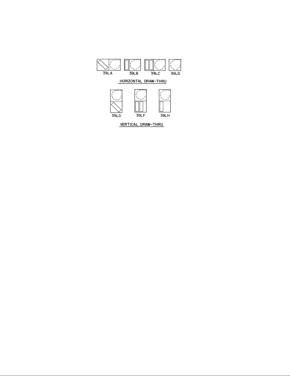
Fig. 1 — Unit Identification
LEGEND
Fig. 2 — 39L Model Number
CV — Constant Volume
DX — Direct Expansion
VAV — Var iab le Air Vol um e
39L C 10 GK C H E A C G - A
Due to the complexity of the (18 position) 39L model number, use the “verify model number”
function in the AHUBuilder® software for a detailed model explanation. The description below
can be used as a general model guide.
Pos. 1-3: Unit Type — 39L Air Handler
Pos. 4: Unit Model — how the unit is configured. Refer to Fig. 3.
Pos. 5-6: Unit Size — Ranges from 03 to 25.
Pos. 7-8: Draw-Thru Options — Includes the sections that will make up the unit.
Pos. 9-12: Coil Type and Arrangement — Describes the coil type (chilled water, CX, heating
only, etc.), fins, rows and circuit information.
Pos. 13-15: Fans — Describes fan discharge, fan speed, and motor information.
Pos. 16: Controls — Describes the AirManager™ control offering (CV, VAV) and the
components that they include.
Pos. 17: F1/F2 Motors — Depending upon positions 13 and 17, F1 or F2 motors may be
substituted for top mounted motor conduit boxes.
Pos. 18: Special Order — Allows copper fin coils and/or .025 in. wall tubes.
Unit Identification —
the 18-digit part number listed on the serial plate. The part
number describes all component, coil, motor, drive, and control
selections. See Fig. 1-3 for unit identification.
The 39L units are identified by
2
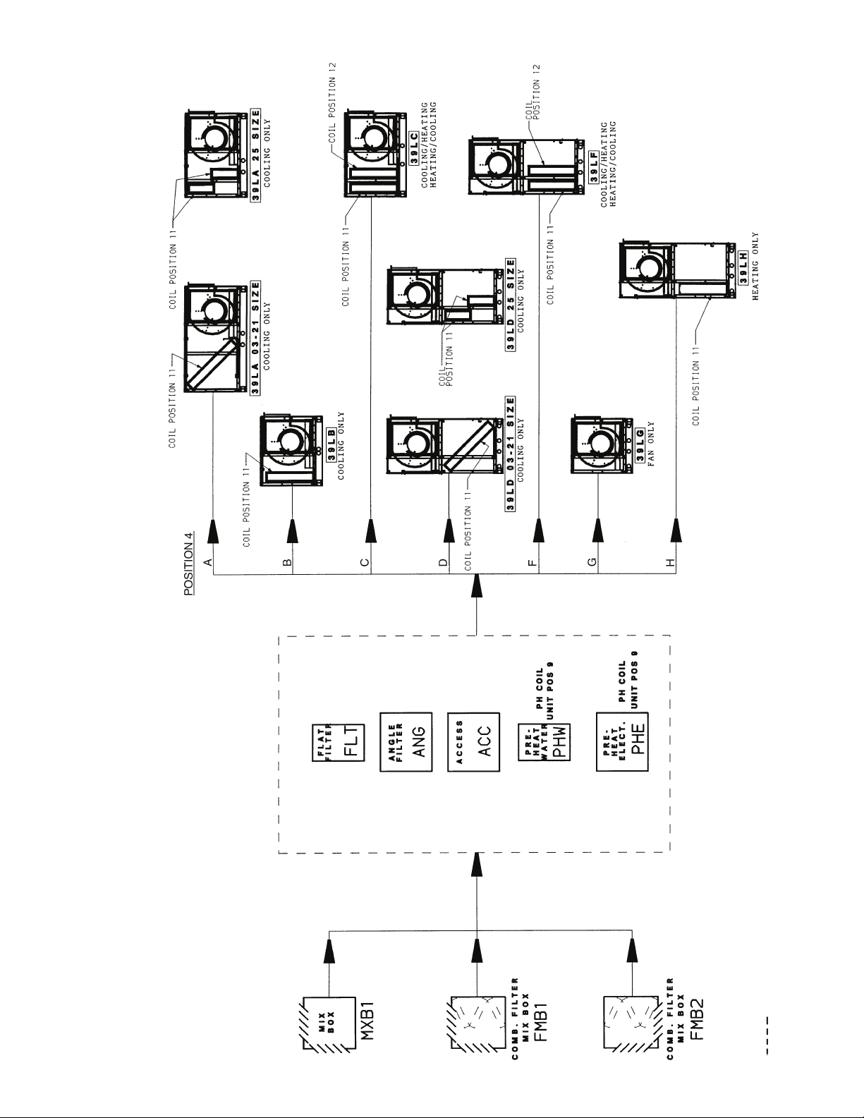
LEGEND
Fig. 3 — Position 4, Unit Configuration Model
(Component Sequence Also Shown)
COMB. — Combination
PH — Preheat
POS. — Positi on
Factory-installed option components
3
PREINSTALLATION
1. Check items received against packing list. Notify Carrier
of any discrepancy.
2. Refer to Fig. 4 for service area requirements.
3. To transfer unit from truck to storage site, refer to rigging
details in Fig. 5 and section on unit rigging for proper
handling. See Table 1 for component weights.
If a fork lift truck is used, lift only from heavy end of skid.
Minimum recommended fork length is 48 inches.
4. Do not stack unit components or accessories during storage. Stacking can cause damage or deformation.
5. If unit is to be stored for more than 2 weeks prior to installation, observe the following precautions:
a. Choose a dry storage site that is reasonably level
and sturdy to prevent undue stress or permanent
damage to the unit structure or components. Do not
store unit on vibrating surface. Damage to stationary bearings can occur. Set unit off ground if in
heavy rain area.
b. Remove all fasteners and other small parts from
jobsite to minimize theft. Tag and store parts in a
safe place until needed.
c. Cover entire unit with a tarp or plastic coverall.
Extend cover under unit if stored on ground.
Secure cover with adequate tiedowns or store
indoors. Be sure all coil connections have protective shipping caps.
d. Monthly — Remove tarp from unit, enter fan
section through access door or through fan inlet,
and rotate fan and motor slowly by hand to redistribute the bearing grease and to prevent bearing
corrosion.
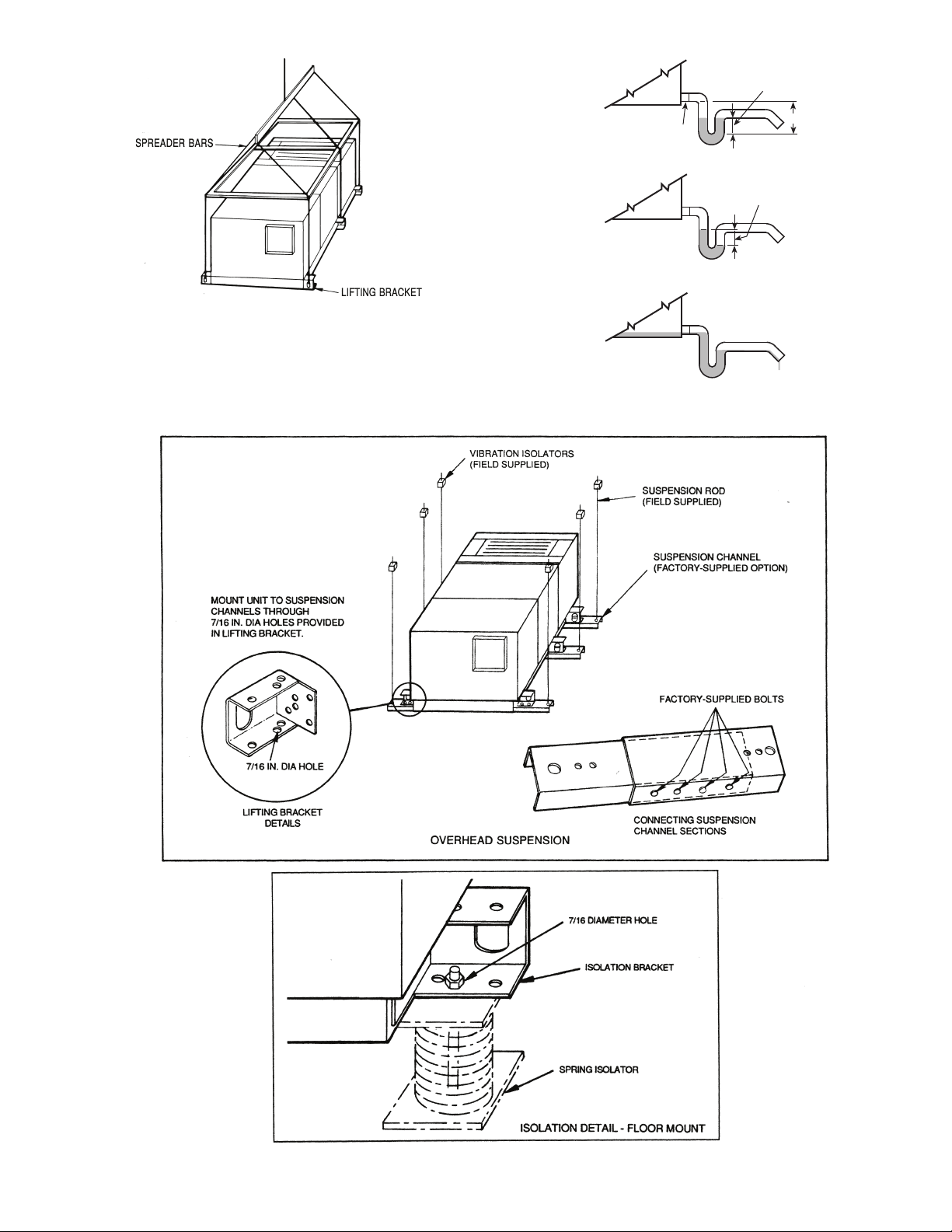
Rigging (Fig. 5) — All 39L units can be rigged by means
of the lifting brackets on bottom of unit.
Units are shipped fully assembled. Do not remove shipping
skids or protective covering until unit is ready for final placement. Use slings and spreader bars as applicable to lift unit. Do
not lift unit by coil connections or headers.
Do not remove protective caps from coil piping connections
until ready to connect piping.
Do not remove protective cover or grease from fan shaft until ready to install sheave.
Lay rigid temporary protection such as plywood walkways
in unit to prevent damage to insulation or bottom panel during
installation.
Suspended Units — Figure 6 shows overhead suspen-
sion of unit using optional factory-supplied suspension
channels.
Each support channel consists of 2 pieces, the smaller of
which fits inside the larger one. This allows the channel to be
adjusted to the required length for installation.
Channels are shipped on top of the unit. The 2 sections of
each channel are shipped one inside the other, and are held in
place during shipping by the panel screws in the top panel.
Hardware required for installation of suspension channels is
shipped in a package inside the fan section.
At least 2 suspension channels are shipped with each fan
and coil unit. One or more extra channels will be supplied
depending on the number of accessories ordered. Be sure to
install all the suspension channels shipped with a unit. Refer to
39L Isolator Mounting (Suspended Unit) certified drawing for
details.
To install suspension channels:
1. Remove panel screws to free suspension channels for installation. Replace screws in top panel.
2. Adjust channel to required length by sliding one channel
section inside the other. The channel must extend at least
9 in. but not more than 12 in. beyond the edge of the unit.
Set length of channel by installing factory-supplied bolts
through the overlapping channel sections.
3. Mount unit to suspension channel using factory-supplied
nuts and bolts through
ing bracket.
4. Install field-supplied suspension rods through
ameter holes provided at outer edges of channel. Be sure
hanger rods are securely fastened in place.
7
/16-in. diameter holes in unit lift-
9
/16-in. di-
Service Clearance — Provide adequate space for unit
service access (fan shaft and coil removal, filter removal, motor access, damper linkage access, etc.) as shown in Fig. 4.
Condensate Drain — To prevent excessive build-up of
condensate in drain pan, adequate trap clearance must be provided beneath the unit as indicated in Fig. 7. See Installation,
Condensate Drain section (page 8) for additional details.
External Vibration Isolators — Install vibration iso-
lators per certified drawings, and in accordance with the job
specifications and the instructions of the vibration isolator
manufacturer. The coil piping must be isolated or have a flexible connection to avoid coil header damage because of unit
motion. A flexible connection should be installed at the fan discharge.
Figure 6 shows isolation location for floor mounting or
overhead suspension of unit.
4
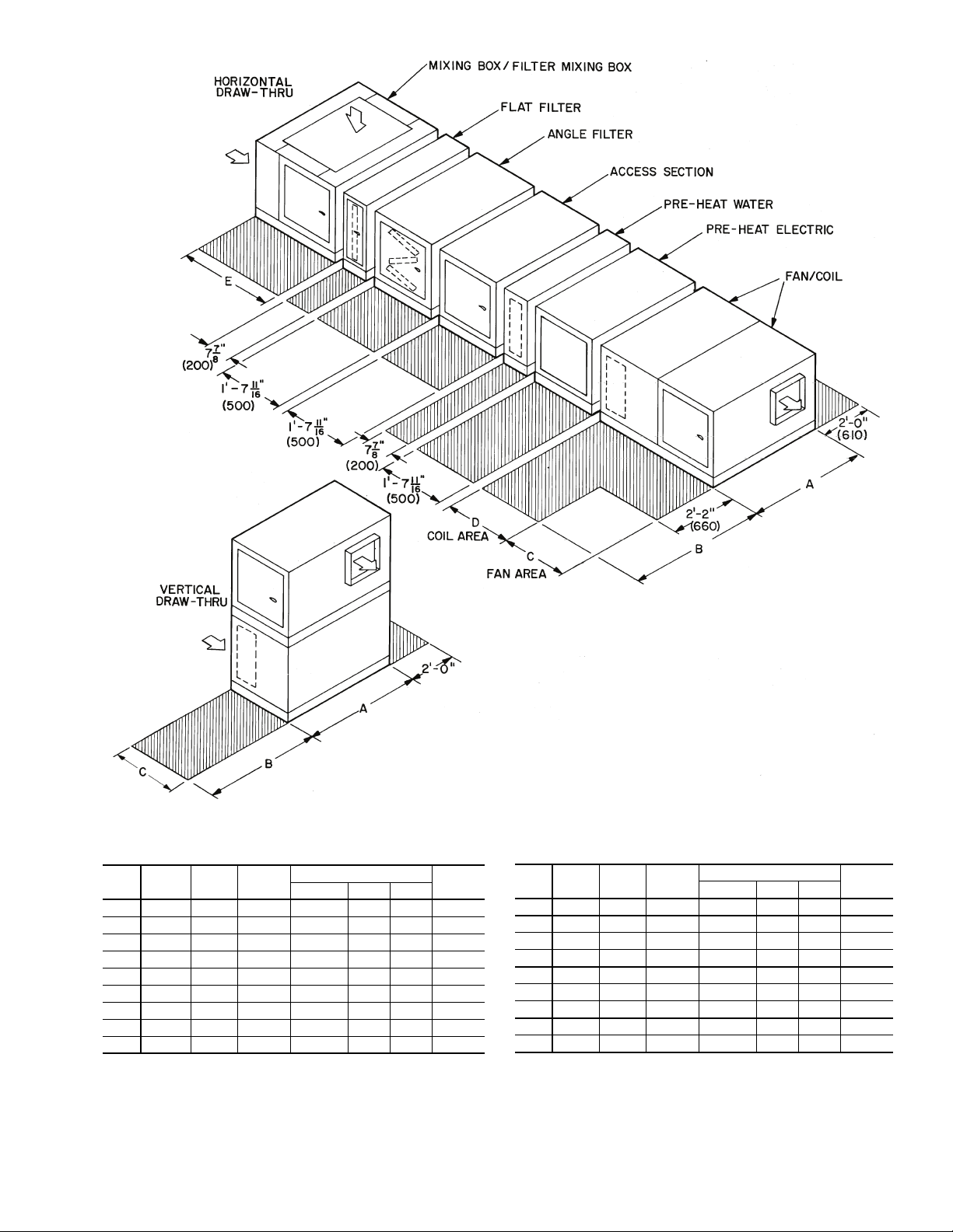
NOTE: Dimensions in ( ) are in mm.
DIMENSIONS (ft-in.)
SIZE A B C
D
E
39LA 39LB 39LC
03 3-17/83-13/41-91/41- 711/160-77/81-33/42- 39/
16
06 3-93/43-95/82-13/161-115/80-77/81-33/42- 39/
16
08 4-111/164-19/162-51/82- 39/160-77/81-33/42- 39/
16
10 4-99/164-97/162-51/82- 39/160-77/81-33/42- 39/
16
12 5-51/165-55/162-51/82- 39/160-77/81-33/42- 39/
16
15 5-51/165-55/163-1 2-119/160-77/81-33/42- 39/
16
18 5-51/165-55/163-415/163- 33/80-77/81-33/42-117/
16
21 6-51/46-51/83-415/163- 33/80-77/81-33/42-117/
16
25 6-51/46-51/84-015/162- 39/160-77/81-33/42-117/
16
DIMENSIONS (mm)
SIZE A B C
D
E
39LA 39LB 39LC
03 952 959 540 500 200 400 700
06 1162 1159 640 600 200 400 700
08 1262 1259 740 700 200 400 700
10 1462 1459 740 700 200 400 700
12 1653 1659 740 700 200 400 700
15 1653 1659 940 900 200 400 700
18 1653 1659 1040 1000 200 400 900
21 1962 1959 1040 1000 200 400 900
25 1962 1959 1240 700 200 400 900
Fig. 4 — Service Area Requirements
5
Table 1 — Physical Data
UNIT SIZE 03 06 08 10 12 15 18 21 25
UNIT WEIGHTS (lb)*
39LA 200 280 411 470 540 620 695 740 820
39LB 150 210 308 352 405 465 521 555 615
39LC 170 238 349 400 459 527 590 629 697
39LD 230 322 472 540 621 713 799 851 943
39LF 230 322 472 540 621 713 799 851 943
39LG 120 168 246 282 324 372 417 444 492
39LH 220 308 452 517 594 682 764 814 902
COMPONENT WEIGHTS (lb)
Mixing Box Section 139 164 193 219 226 244 283 272 311
Filter Mixing Box 150 173 208 227 245 279 327 340 395
Angle Filter Section 75 82 97 107 114 134 140 159 185
Flat Filter Section 37 43 48 50 55 74 75 86 90
Access Section 48 55 60 64 68 74 77 87 92
Preheat (Water) Section 36 42 43 46 49 52 54 53 57
Preheat (Electric) Section 49 56 61 66 72 74 76 87 89
TYPICAL DRY COIL WEIGHTS (lb)
Large Face Area Cooling Coils,
1
/
-in. OD (Chilled Water & DX)†
2
4-Row 56 84 98 109 137 178 198 251 280
6-Row 63 95 123 138 174 234 270 327 363
Small Face Area Cooling Coils,
1
/
-in. OD (Chilled Water & DX)†
2
4-Row 45 72 91 105 133 161 182 211 238
6-Row 53 85 113 129 162 197 225 270 307
8-Row 61 92 129 143 189 228 263 324 377
Hot Water Coils,
1-Row 19 34 38 48 58 62 77 86 95
2-Row 28 43 51 61 76 89 104 117 130
Steam Coils, 1-row, 1-in. OD
6-FPI 50 70 85 95 110 135 150 180 215
9-FPI 55 80 100 115 125 155 175 214 256
12-FPI 60 85 115 130 145 180 205 248 297
FAN
Wheel Diameter (in.) 9
Wheel Width (in.) 7
Shaft Diameter (in.) 3/4 1
Maximum Fan Rpm 2500 2000 2000 1600 1600 1400 1300 1100 1000
OPERATING CHARGE, R-22 (lb)
4-Row Coil 1-2 2-3 3-4 4-5 4-5 5- 6 6- 7 6- 8 6- 9
6-Row Coil 1-2 2-4 5-6 5-6 6-8 8-10 9-11 11-13 11-16
8-Row Coil 2-3 3-5 5-6 5-7 7-9 10-12 12-14 13-19 16-24
COIL VOLUME (gal. water)
Chilled Water,
Large Face Area
4-Row 2.5 3.5 4.5 5.2 5.6 7.3 8.5 10.4 12.0
6-Row 3.2 4.7 6.0 6.8 7.7 10.1 11.7 14.2 16.3
Chilled Water,
Small Face Area
4-Row 2.1 3.3 3.9 4.1 5.1 6.3 7.3 8.7 9.8
6-Row 2.4 3.7 5.1 5.9 6.6 8.3 9.5 11.8 13.5
8-Row 2.7 4.1 6.4 7.4 8.4 10.7 12.1 14.7 17.2
Hot Water,
1-Row 0.5 0.8 1.0 1.3 1.5 1.8 2.1 2.5 2.9
2-Row 0.7 1.3 1.6 2.0 2.4 2.9 3.4 4.0 4.8
COOLING COILS
Chilled Water
(4, 6 Row) Large Face Area
Face Area (sq ft) 3.63 5.90 7.90 9.54 11.18 14.91 17.71 21.6 25.0
Number of Tubes/Face 16 20 24 24 24 32 38 38 44
Finned Tube Length (in.) 26.1 34.0 37.9 45.8 53.7 53.7 53.7 65.5 65.5
Chilled Water
(4, 6, 8 Row) Small Face Area
Face Area (sq ft) 2.72 4.72 6.58 7.95 9.32 12.12 13.98 17.1 20.5
Number of Tubes/Face 12 16 20 20 20 26 30 30 36
Finned Tube Length (in.) 26.1 34.0 37.9 45.8 53.7 53.7 53.7 65.5 65.5
1
DX
/
-in. OD Tube
2
(4, 6 Row) Large Face Area
Face Area (sq ft) 3.63 5.90 7.90 9.54 11.18 14.91 17.71 21.6 25.0
Finned Tube Length (in.) 26.1 34.0 37.9 45.8 53.7 53.7 53.7 65.5 65.5
1
/
-in. OD Tube
DX
2
(4, 6, 8 Row) Small Face Area
Face Area (sq ft) 2.72 4.72 6.58 7.95 9.32 12.12 13.98 17.1 20.5
Finned Tube Length (in.) 26.1 34.0 37.9 45.8 53.7 53.7 53.7 65.5 65.5
HEATING COILS
Hot Water
U-Bend (1, 2 Row)
Face Area (sq ft) 2.72 4.72 6.58 7.95 9.32 12.12 13.98 17.1 20.5
Number Tubes/Face 12 16 20 20 20 26 30 30 36
Finned Tube Length (in.) 26.1 34.0 37.9 45.8 53.7 53.7 53.7 65.5 65.5
Steam 1-in. OD (1 Row)
Face Area (sq ft) 2.13 4.18 6.22 7.53 8.85 11.06 13.28 16.2 18.9
Number Tubes/Face 4688 8 10121214
Finned Tube Length (in.) 25.5 33.4 37.3 45.2 53.1 53.1 53.1 53.1 64.9
LEGEND *Less coil.
DX — Direct Expansion
FPI — Fins Per Inch
1
/
2
1
/
-in. OD Tube,
2
1
/
-in. OD Tube,
2
1
/
-in. OD Tube
2
1
/
-in. OD Tube,
2
1
/
-in. OD Tube
2
1
/
-in. OD Tube,
2
-in. OD†
1
/
2
1
/
8
5
12
/
1
9
/
2
3
/
16
5
12
/
8
1
11
3
1
/
15 15 18
8
/
16
1
11
8
/
8
3
1
/
16
15 15 13
3
1
/
16
1
/
7
1
/
16
20 20 25
8
1
/
2
7
1
/
16
18 15
7
1
/
16
11
1
/
16
†Coils have 14 aluminum fins per inch on copper tubes.
6
DIFFERENTIAL
NOTE: Lift in one piece. Use slings and spreader bars at each lifting
bracket.
Fig. 5 — Unit Rigging Details
Fig. 7 — Condensate Drain
Fig. 6 — Unit Support Details
1
DRAIN NIPPLE
FAN OFF
TRAP CONDITION WHEN FAN STARTS
COOLING COIL
DRAIN PAN
FAN RUNNING AND CONDENSATE DRAINING
H
DIFFERENTIAL
2
7
INSTALLATION
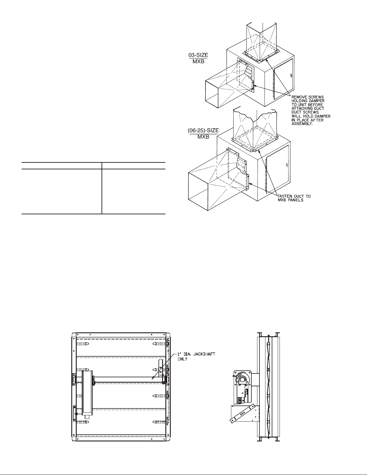
MXB — Mixing Box
Fig. 9 — Mixing Box Ductwork Attachment
Fig. 8 — Typical Mixing Box Actuator Mounting
Mixing Box
DAMPER ACTUATORS — The 39L mixing boxes are supplied with low leak dampers and blade and edge seals. Damper
operating torques are shown in Table 2.
The actuator and mounting brackets are field supplied and
may be mounted inside or outside the unit. A typical inside
mounting bracket is shown in Fig. 8. For external mounting of
actuators, drill or punch a hole in the exterior panel.
NOTE: If the unit is shipped with AirManager™ controls,
actuator(s) are factory-supplied. Refer to Table. 3.
To ensure torque is transmitted equally to both damper sections, actuator must be connected to the 1-in. hollow jackshaft
that drives the interconnecting linkage bar. Connection to any
other shaft is not recommended.
DUCTWORK ATTACHMENT — Ductwork should be
flanged out and attached to the mixing box panels as shown in
Fig. 9. See Fig. 10 for duct connection sizes.
Table 2 — Mixing Box Damper Operating Torque
(in.-lb)
39L UNIT SIZE TORQUE
03 20
06 20
08 26
10 29
12 33
15 41
18 52
21 56
25 76
NOTES:
1. Torque values are based on interconnected dampers driven by
one operator. For units with separate operators for each
damper, calculate torque as follows: Table values x .80 = torque
per damper section.
2. Damper shaft moves 90 degrees from open to closed position.
Condensate Drain — Install a trapped condensate drain
line at unit drain connection. Use 1-in. standard pipe.
Measure maximum design negative static pressure upstream from the fan. Referring to Fig. 7, height “H” must be
equal to or larger than negative static pressure at design operating conditions. Prime enough water in trap to prevent losing
seal (Differential 1). When the fan starts, Differential 2 is equal
to the maximum negative static pressure.
Provide freeze-up protection as required.
8
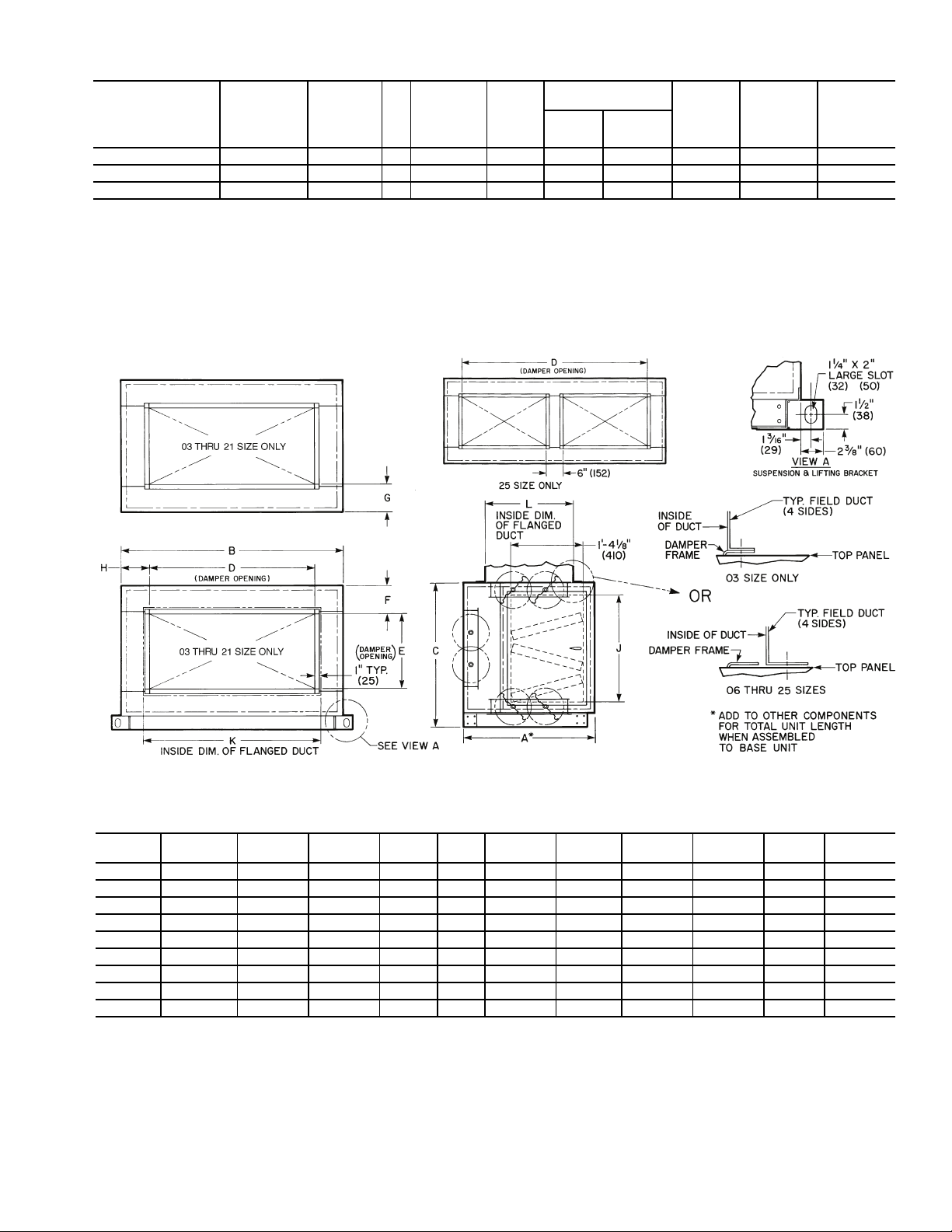
Table 3 — Recommended Actuators
NOTES:
1. Hand is determined by the location of the fan drive and/or coil connection when viewed while facing the direction toward which air is flowing.
2. Dimensions in ( ) are in millimeters.
DIMENSIONS (ft-in.)
Fig. 10 — Mixing Box Duct Connections
UNIT
39L-
A B C D E F G H J K L
03 2- 39/
16
3-17/
8
2-01/
4
1- 5 1-5 0- 15/
8
0-61/
16
0-101/
2
1-43/
4
1-51/
4
1- 51/
4
06 2- 39/
16
3-93/
4
2-43/
16
1-11 1-5 0- 41/
8
0-61/
16
0-113/
8
1-811/
16
2-11/
4
1- 71/
4
08 2- 39/
16
4-111/
16
2-81/
8
3- 1 1-5 0- 61/
16
0-61/
16
0- 63/
8
2-05/
8
3-31/
4
1- 71/
4
10 2- 39/
16
4-99/
16
2-81/
8
3- 5 1-5 0- 61/
16
0-61/
16
0- 85/
16
2-05/
8
3-71/
4
1- 71/
4
12 2- 39/
16
5-57/
16
2-81/
8
3-11 1-5 0- 61/
16
0-61/
16
0- 91/
4
2-05/
8
4-11/
4
1- 71/
4
15 2- 39/
16
5-57/
16
3-4 3-11 1-9 0- 8 0-41/
16
0- 91/
4
2-81/
2
4-11/
4
1-111/
4
18 2-117/
16
5-57/
16
3-715/
16
3-11 2-3 0- 7 0-5 0- 91/
4
3-07/
16
4-11/
4
2- 51/
4
21 2-117/
16
6-51/
4
3-715/
16
3-11 2-5 0- 6 0-4 1- 31/
8
3-07/
16
4-11/
4
2- 71/
4
25 2-117/
16
6-51/
4
4-313/
16
5- 4 2-5 0- 97/
8
0-4 0- 65/
8
3-85/
16
5-61/
4
2- 71/
4
ACCESSORY
PACKAGE
NO.
ACTUATOR
PART N O.
VOLTAGE
(50/60 Hz)
VA
ROUND
SHAFT
SIZE
MIN-MAX
(in.)
TIMING
(sec)
DAMPER AREA
(sq ft)
Parallel Opposed
TORQUE
(in.-lb)
MAXIMUM
STROKE
(degrees)
MAXIMUM
LENGTH
33AMACTDMP133 HF27BJ035* 24 10 .750-1.050 150 44 53 133 90 300
33AMACTGV-133 HF27BJ033 24 4 .375- .625 < 150 N/A N/A 133 90 725
33AMACTGV-266 HF27BJ034 24 6 .475- .750 135 N/A N/A 266 90 450
*Actuator is spring-return type.
NOTES:
1. All actuators are direct coupled type, designed to be directly
mounted into jackshaft assembly.
2. All actuators are equipped with a plenum rated cable, factoryterminated to the actuator. Part No. HF27BB035 and 034 are
16 ft, HF27BB033 is 9.5 ft.
3. Damper areas are nominal and based on low leakage type
dampers.
4. For larger damper assemblies, multiple activators may be used.
5. Part No. HF27BB033 and 034 are designed for inlet guide vane
and face and bypass applications, but may be used for external
relief dampers if spring return is not required.
WIRE
(ft)
9

Inlet Guide Vane (IGV) Actuators — The control
board positions the unit IGVs in order to maintain the duct static pressure, as measured by the static pressure transducer, at the
required set point. The IGV actuator is electrically connected to
the control board and receives a signal whenever the guide
vane position needs to be adjusted. The guide vane actuator is
mounted to the IGV jackshaft, and secured to the jackshaft
mounting member in order to prevent rotation.
For factory-installed controls which are ordered with the
unit, the IGV actuator is properly sized and factory mounted to
the IGV jackshaft. The actuator wiring is routed across the fan
section to a junction box which is mounted to the exterior of
the unit. Two compatible actuators are available for field
installation. Both actuators are supplied with a length of
plenum rated cable to facilitate installation inside the unit. See
Table 3 for actuator specifications and typical applications.
Jackshaft and IGV linkage setup adjustments are extremely
important for proper IGV performance and static pressure control. Closely follow all instructions.
To install the IGV actuators, perform the following:
1. Disconnect power to the fan motor prior to performing
the installation.
2. Open the fan access door and locate the IGV jackshaft.
Measure the IGV jackshaft diameter. Verify that the size
is within the range of the actuator chosen. See Table 3.
3. Loosen the U-bolt locking nuts on the actuator.
4. Slip the actuator over the IGV jackshaft. Align the actuator parallel with the frame member which supports the
jackshaft.
5. Take the anti-rotation bracket supplied with the actuator
and, with the center locking pin pointed outward, slip the
pin into the slot at the far end of the actuator. Seat the pin
into the center of the groove provided. If the anti-rotation
bracket is not seated against the frame member, measure
the distance from the member and remove the antirotation bracket from the actuator. Bend the bracket to the
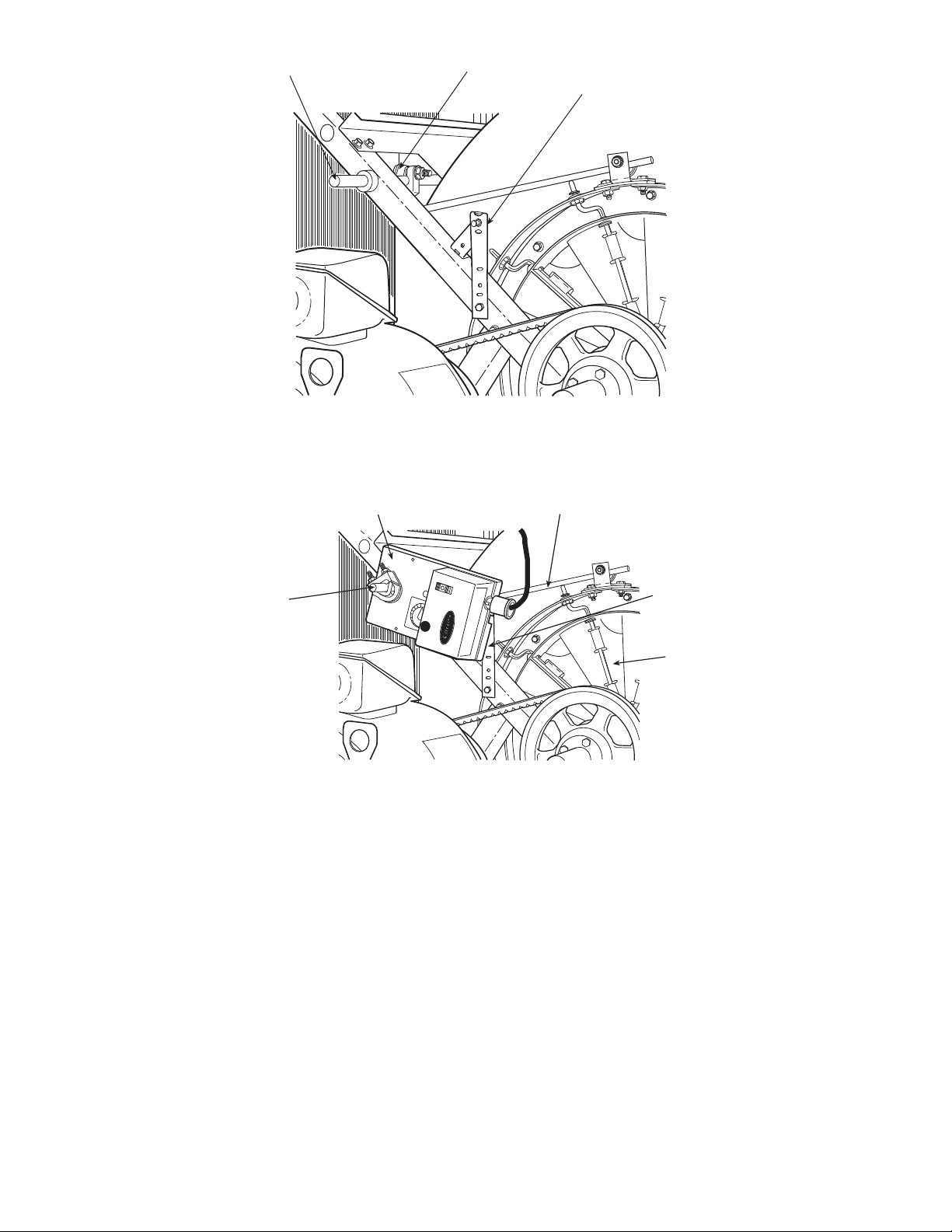
required offset. See Fig. 11.
6. With the anti-rotation bracket installed in the actuator
groove, locate the hole in the bracket, closest to the pin,
which is fully in contact against the frame. Mark this hole
location on the frame. Trace the outline of the bracket on
the frame so that it can be re-aligned again when
removed.
7. Remove the bracket and actuator. Drill a pilot hole at the
location marked from Step 6. Install one screw through
the hole. Re-align the bracket with the outline made previously and tighten the screw.
8. Locate and mark the hole on the opposite end of the
bracket, closest to the pin, which contacts the frame. Drill
a pilot hole in this location and install the remaining
screw. Remove the first screw.
9. Install the actuator on the jackshaft and while moving
into position, adjust the free end of the anti-rotation
bracket so that the pin fully locks into the slot provided in
the actuator. Once the actuator is adjusted into position,
install the remaining screw into the anti-rotation bracket.
See Fig. 12.
10. Rotate the jackshaft to fully close the IGVs. Press the
release button (BLACK) on the face of the actuator, and
rotate the clamp in the same direction that closed the
IGVs, until the actuator stop is reached. With the release
still pressed, rotate the actuator clamp from the full closed
position to the .1 mark and release the actuator release
button. Lock the U-bolt clamp into position to secure the
actuator to the IGV jackshaft.
11. If a second actuator is required, repeat the process for a
second actuator. The second actuator mounts on the opposite side of the fan on the opposite end of the jackshaft.
ACTUATOR WIRING — To wire the actuator, perform the
following:
1. Each actuator is supplied with a length of plenum rated
cable. Route the cable from the actuator to the exterior of
the unit. Allow a sufficient service loop to provide free
movement of the fan sled.
2. At the desired location for field connection, drill a
hole (two holes within a
7
/8-in. diameter are required if
3
/8-in.
two actuators are used) through the unit and route the cable through the hole.
3. Install a field-supplied bushing to protect the cable and
seal the hole, using a suitable silicone sealer such as
Form-A-Gasket® by Permatex to secure the cable and
prevent air leakage.
4. Remove the center back plug from a field supplied 2 x
4-in. electrical junction box. Route the cable(s) through
the hole and secure the box to the unit using 2 fieldsupplied no. 10 drill/tap screws.
5. Use a 3 or 4-conductor, 18 AWG cable or individual
18 AWG wiring using RED, WHITE, and BLACK color
coding to connect the actuator to the control box.
6. Inside the control box, connect all RED wire(s)
together. Secure with wire nuts or closed end crimp type
connectors.
7. Inside the control box, connect all BLACK wire(s) together. Secure with wire nuts or closed end crimp type
connectors.
8. Inside the control box, connect all WHITE wire(s) together. Secure with wire nuts or closed end crimp type
connectors.
9. At the control box, strip
conductor. Equip each conductor with a
1
/4-in. of insulation from each
1
/4-in. female
spade type crimp connector.
10. Connect the RED wire to terminal T37 on the control
board.
11. Connect the WHITE wire to terminal T39 on the control
board.
12. Connect the BLACK wire to terminal no. 3 on the TB2
terminal block in the control box.
13. Check the rotation of the actuator. The switch is factory
set in the A position which provides clockwise rotation to
open the IGVs. If counterclockwise rotation is required to
open the IGVs, reset the actuator switch to the B position.
To adjust the jackshaft linkage, perform the following:
1. Refer to Fig. 12. Close the IGVs fully.
2. Loosen the crankarm and rods. Press the release button
on the actuator and rotate it to the .9 mark for right hand
units or the .1 mark for left hand units. Rotate the crankarm on the jackshaft to a position which is about 30 degrees from parallel alignment with the rod connecting the
IGV.
3. Tighten the crankarm into this position.
4. Close the IGVs fully by hand. Tighten the rod into
position.
5. Test the actuator and IGV operation. Be sure the IGVs
fully close and open. Re-adjust the position of the swivel
joint outward if full IGV travel is not reached with the
actuator 90 degree rotation. If the IGVs reach the end of
full travel in less than 90 degrees of actuator rotation,
adjust the swivel joint inward toward the jackshaft. After
making any adjustment, repeat Steps 2-5.
10
Install Fan Motor — For field installation of motors, be
JACKSHAFT CRANKARM
ANTIROTATION STRAP
INSTALLED (ACTUATOR
NOT SHOWN FOR
CLARITY)
IGV ACTUATOR
CONNECTING ROD
ANTIROTATION
STRAP
INLET GUIDE
VANES (IGV)
IGV
JACKSHAFT
Fig. 11 — IGV Actuator Bracket Installation
Fig. 12 — IGV Actuator Mounting
sure electrical junction box is toward the center of the unit.
This is necessary for drive and belts to be properly tightened.
Use smallest slots in motor mounting base that will accommodate motor and allow minimum overhang (Fig. 13). Be sure
that motor holddown bolts are tight on field-installed motor.
JUNCTION BOX CONDENSATE PREVENTION — When
air handlers are installed outdoors in a high humidity environment or indoors where the apparatus room is used as a fresh air
plenum, precautions must be taken to prevent condensation
from forming inside the junction box of the internally mounted
motor.
Standard installation practice is to mount the motor starter
or fused disconnect box adjacent to the air handler and enclose
the power wiring to the motor in flexible conduit.
The sheet metal housing of the disconnect switch or motor
starter is not airtight (even when a box meeting NEMA
[National Electrical Manufacturers Association] IV standards
is used). Thus, warm moist air can migrate through the flexible
conduit to the junction box on the motor. With the motor
located inside the unit, the motor temperature is that of the cool
11
supply air; thus, condensate can form inside the junction box
and, possibly, on the live terminal lugs.
To prevent the moist air from migrating through the conduit
to the motor, seal the power wires inside the flexible conduit at
the motor starter or fused disconnect.
Use a nonconductive, nonhardening sealant. Permagum
(manufactured by Schnee Morehead) or sealing compound,
thumb grade (manufactured by Calgon), are acceptable
materials.
POWER KNOCKOUTS — Panels are not provided with
knockouts for the fan motor power wiring. Openings must be
drilled or punched in the exterior panels of the unit. It is recommended that power wiring be routed through the discharge
panel whenever possible, as this panel is rarely removed for
service access.
Install Sheaves on Motor and Fan Shafts —
Factory-supplied drives are prealigned and tensioned, however,
Carrier recommends that you check the belt tension and alignment before starting the unit. Always check the drive alignment after adjusting belt tension.
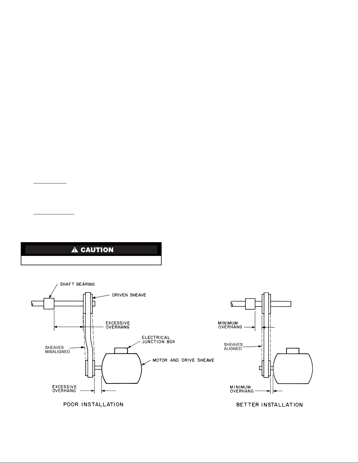
When field installing or replacing sheaves, install sheaves
Fig. 13 — Determining Sheave-Shaft Overhang
on fan shaft and motor shaft for minimum overhang. (See
Fig. 13.) Use care when mounting sheave on fan shaft; too
much force may damage bearing. Remove rust-preventative
coating or oil from shaft. Make sure shaft is clean and free of
burrs. Add grease or lubricant to bore of sheave before
installing.
The 39L fan, shaft, and drive pulley are balanced as a complete assembly to a high degree of accuracy. If excessive unit
vibration is present after fan pulley replacement, the unit must
be rebalanced. For drive ratio changes, always reselect the motor pulley — do not change the fan pulley.
ALIGNMENT — Make sure that fan shafts and motor shafts
are parallel and level. The most common causes of misalignment are nonparallel shafts and improperly located
sheaves. Where shafts are not parallel, belts on one side are
drawn tighter and pull more than their share of the load. As a
result, these belts wear out faster, requiring the entire set to be
replaced before it has given maximum service. If misalignment
is in the sheave, belts will enter and leave the grooves at an
angle, causing excessive belt cover and sheave wear.
1. Shaft alignment can be checked by measuring the
distance between the shafts at 3 or more locations. If the
distances are equal, then the shafts will be parallel.
2. Sheave alignment:
Fixed sheaves
— To check the location of the fixed
sheaves on the shafts, a straightedge or a piece of string
can be used. If the sheaves are properly lined up the string
will touch them at the points indicated by the arrows in
Fig. 14.
Adjustable sheave
— To check the location of adjustable
sheave on shaft, make sure that the centerlines of both
sheaves are in line and parallel with the bearing support
channel. See Fig. 14. Adjustable pitch drives are installed
on the motor shaft.
3. Rotating each sheave a half revolution will determine
whether the sheave is wobbly or the drive shaft is bent.
Correct any misalignment.
4. With sheaves aligned, tighten cap screws evenly and
progressively.
NOTE: There should be a
1
/8-in. to 1/4-in. gap between
the mating part hub and the bushing flange. If gap is
closed, the bushing is probably the wrong size.
5. With taper-lock bushed hubs, be sure the bushing bolts
are tightened evenly to prevent side-to-side pulley wobble. Check by rotating sheaves and rechecking sheave
alignment. When substituting field-supplied sheaves for
factory-supplied sheaves, consider that the fan shaft
sheave has been factory balanced with fan and shaft as an
assembly. For this reason, substitution of motor sheave is
prefer-able for final speed adjustment.
Install V-Belts — When installing or replacing belts, al-
ways use a complete set of new belts. Mixing old and new belts
will result in the premature wear or breakage of the newer
belts.
1. Always adjust the motor position so that V-belts can be
installed without stretching over grooves. Forcing belts
can result in uneven stretching and a mismatched set of
belts.
2. Do not allow belt to bottom out in sheave.
3. Tighten belts by turning motor-adjusting jackscrews.
Turn each jackscrew an equal number of turns.
4. Equalize belt slack so that it is on the same side of belt for
all belts. Failure to do so may result in uneven belt
stretching.
5. Tension new drives at the maximum deflection force
recommended (Fig. 15).
With adjustable sheave, do not exceed maximum fan rpm.
12

Fig. 14 — Sheave Alignment
PD — Pitch Diameter, inches
Fig. 15 — Fan Belt Tension Data
BELT
CROSS
SECTION
SMALL
SHEAVE
PD RANGE
(in.)
DEFLECTION FORCE — LB
Super
Belts
Notch
Belts
Steel Cable
Belts
Min Max Min Max Min Max
A
3.0- 3.6 3 4
1
/437/851/234
3.8- 4.8 3
1
/2541/261/433/443/
4
5.0- 7.0 4 51/2567/841/451/
4
B
3.4- 4.2 4 5
1
/253/4841/251/
2
4.4- 5.6 51/871/861/291/853/471/
4
5.8- 8.6 63/883/473/8101/8783/
4
C
7.0- 9.4 11
1
/4143/8133/4177/8111/414
9.6-16.0 14
1
/8181/2151/4201/4141/4173/
4
3V
2.65-3.65 3
1
/2537/851/2——
4.12-6.90 4
3
/467/851/477/8——
5V
4.40-6.70 — — 10 15 — —
7.1-10.9 10
1
/2153/4127/8183/4——
11.8-16.0 13 19
1
/215 22 — —
8V
12.5-17.0 27 40
1
/2——— —
18.0-22.4 30 45 — — — —
Fig. 16 — Fan Section Label
NOTICE
TENSION BELTS TO SPECIFICATION
SHOWN ON DRIVE LABEL. OVER
TENSIONING BELTS WILL SEVERELY
REDUCE BELT AND BEARING LIFE.
REPLACEMENT PARTS
BEARINGS
DRIVE _______________________
FREE ________________________
SHAFT ________________________
WHEEL ________________________
INLET CONE ____________________
TO ORDER REPLACEMENT PARTS,
CONTACT: RCD
(REPLACEMENT COMPONENTS DIVISION)
1-800-443-4410
6. To determine correct belt tension, use the deflection
formula given below and the tension data from Fig. 15 as
follows:
EXAMPLE:
Given
Solution
1. From Fig. 15 find that deflection force for type A, super
belt with 5-in. small sheave PD is 4 to 5
2.
3. Increase or decrease belt tension until force required for
1
Check belt tension at least twice during first operating
day. Readjust as required to maintain belt tension within
the recommended range.
With correct belt tension, belts may slip and squeal
momentarily on start up. This slippage is normal and disappears after unit reaches operating speed. Excessive belt tension
shortens belt life and may cause bearing and shaft damage.
After run-in, set belt tension at lowest tension at which belts
will not slip during operation.
Record information on the label (Fig. 16) found on the door
of the fan section.
Belt Span 16 in.
Belt Cross-Section A, Super Belt
Small Sheave PD 5 in.
Deflection =
(Belt Span)
64
Deflection =
/4-in. deflection is 51/2 lb.
16
64
1
/2 lb.
13

Water and Steam Coil Piping Recommendations
Fig. 17 — Coil Connections and Lifting Points
GENERAL — Use straps around the coil casing or the lifting
holes (see Fig. 17) to lift and place the coil.
To prevent damage to the coil or coil headers: Do not use
the headers to lift the coil. Support the piping and coil connections independently. Do not use the coil connections to
support piping. When tightening coil connections, use a
backup wrench on the nozzles.
Piping practices are outlined in the Carrier System Design
Manual, Part 3, Piping Design. See Tables 4-6 for circuiting data.
WATER COILS — Typically, coils are piped by connecting
the supply at the bottom and the return at the top. See Fig. 17.
This is not always the case, especially if the coil hand has been
changed in the field. Coils must be piped for counterflow; otherwise, a capacity reduction of 5% for each coil row will result.
To ensure counterflow, chilled water coils are piped so that the
coldest water meets the coldest air. Hot water coils are piped so
that the warmest water meets the warmest air.
STEAM COILS — Position the steam supply connection at
the top of the coil, and the return (condensate) connection at the
bottom. The coil tubes must incline downwards toward
the return header connection for condensate drainage. See
Fig. 18-22.
Figure 18 illustrates the normal piping components and the
suggested locations for high, medium, or low-pressure steam
coils. The low-pressure application (zero to 15 psig) can
dispense with the ¼-in. petcock for continuous venting located
above the vacuum breaker (check valve).
Note the horizontal location of the 15-degree check valve,
and the orientation of the gate/pivot. This valve is intended to
relieve any vacuum forming in the condensate outlet of a
condensing steam coil, and to seal this port when steam
pressure is again supplied to the coil. It must not be installed in
any other position, and should not be used in the supply line.
For coils used in tempering service, or to preheat outside air,
install an immersion thermostat in the condensate line ahead of
the trap. This will shut down the supply fan and close the outdoor damper whenever the condensate falls to a predetermined
point, perhaps 120 F.
NOTE: Do NOT use an immersion thermostat to override a
duct thermostat and open the steam supply valve.
For vacuum return systems, the vacuum breaking check
valve would be piped into the condensate line between the trap
and the gate valve instead of open to the atmosphere.
Figure 19 illustrates the typical piping at the end of every
steam supply main. Omitting this causes many field problems
and failed coils.
Figure 20 shows the typical field piping of multiple coils.
Use this only if the coils are the same size and have the same
pressure drop. If this is not the case, an individual trap must be
provided for each coil.
Figure 21 shows a multiple coil arrangement applied to a
gravity return, including the open air relief to the atmosphere,
which DOES NOT replace the vacuum breakers.
Figure 22 illustrates the basic condensate lift piping.
Following the piping diagrams in Fig. 18-22, make all connections while observing the following precautions:
• Install a drip line and trap on the pressure side of the
inlet control valve. Connect the drip line to the return
line downstream of the return line trap.
• To prevent scale or foreign matter from entering the con-
trol valve and coil, install a
3
/32-in. mesh strainer in the
steam supply line upstream from the control valve.
• Provide air vents for the coils to eliminate noncondens-
able gases.
• Select a control valve according to the steam load, not
the coils supply connection size. Do not use an oversized
control valve.
• Do not use bushings that reduce the size of the header
return connection. The return connection should be the
same size as the return line and reduced only at the
downstream trap.
• To lift condensate above the coil return line into over-
head steam mains, or pressurized mains, install a pump
and receiver between the condensate trap and the
pressurized main. Do not try to lift condensate with
modulating or on-and-off steam control valves. Use only
15-degree check valves, as they open with a lower water
head. Do not use 45-degree or vertical-lift check valves.
• Use float and thermostatic traps. Select the trap size
according to the pressure difference between the steam
supply main and the return main.
• Load variations can be caused by uneven inlet air distri-
bution or temperature stratification.
• Drain condensate out of coils completely at the end of
the heating season to prevent the formation of acid.
Coil Freeze-Up Protection
WATER COILS — If a chilled water coil is applied with outside air, provisions must be made to prevent coil freeze-up.
Install a coil freeze-up thermostat to shut down the system if
any air temperature below 36 F is encountered entering the
water coil. Follow thermostat manufacturer’s instructions.
14

When a water coil is applied downstream of a direct-
NOTES:
1. Flange or union is located to facilitate coil removal.
2. Flash trap may be used if pressure differential between steam
and condensate return exceeds 5 psi.
3. When a bypass with control is required.
4. Dirt leg may be replaced with a strainer. If so, tee on drop can
be replaced by a reducing ell.
5. The petcock is not necessary with a bucket trap or any trap
which has provision for passing air. The great majority of high
or medium pressure returns end in hot wells or deaerators
which vent the air.
Fig. 18 — Low, Medium or
High Pressure Coil Piping
expansion (DX) coil, a freeze-up thermostat must be installed
between the DX and water coil and electrically interlocked to
turn off the cooling to prevent freeze-up of the water coil.
For outdoor-air application where intermittent chilled water
coil operation is possible, one of the following steps should be
taken:
• Install an auxiliary blower heater in cabinet to maintain
above-freezing temperature around coil while unit is
shut down.
• Drain coils and fill with an ethylene glycol solution suit-
able for the expected cold weather operation. Shut down
the system and drain coils. See Service section, Winter
Shutdown, page 30.
STEAM COILS — When used for preheating outdoor air in
pressure or vacuum systems, an immersion thermostat to control outdoor-air damper and fan motor is recommended. This
control is actuated when steam supply fails or condensate temperature drops below an established level, such as 120 to 150 F.
A vacuum breaker should also be used to equalize coil pressure
with the atmosphere when steam supply throttles close. Steam
should not be modulated when outdoor air is below 40 F.
On low-pressure and vacuum steam-heating systems, the
thermostat may be replaced by a condensate drain with a thermal element. This element opens and drains the coil when condensate temperature drops below 165 F. Note that condensate
drains are limited to 5 psig pressure.
INNER DISTRIBUTING TUBE STEAM COILS — The
inner distributing tube (IDT) steam coil used in the Carrier
39M air-handling units has an inner tube pierced to facilitate
the distribution of the steam along the tube's length. The outer
tubes are expanded into plate fins. The completed assembly
includes the supply and condensate header and side casings
which are built to slant the fin/tube bundle back toward the
condensate header. The slanting of the assembly ensures that
condensate will flow toward the drains. This condensate must
be removed through the return piping to prevent premature
failure of the coil. The fin/tube bundle is slanted vertically for
horizontal airflow coils, and horizontally for vertical airflow coils.
IDT Steam Coil Piping
— The following piping guidelines
will contribute to efficient coil operation and long coil life:
1. Use full size coil outlets and return piping to the steam
trap. Do not bush return outlet to the coil. Run full size to
the trap, reduce at the trap.
2. Use float and thermostatic (F & T) traps only for condensate removal. Trap size selection should be based on the
difference in pressure between the steam supply main and
the condensate return main. It is good practice to select a
trap with 3 times the condensate rating of the coil to
which it is connected.
3. Use thermostatic traps for venting only.
4. Use only
1
/2-in., 15-degree swing check valves installed
horizontally, piped open to atmosphere, and located at
least 12 in. above the condensate outlet. Do not use
45-degree, vertical lift and ring check valves.
5. The supply valve must be sized for the maximum anticipated steam load.
6. Do not drip steam mains into coil sections. Drip them on
the pressure side of the control valve and trap them into
the return main beyond the trap for the coil.
7. Do not use a single trap for two or more coils installed in
series. Where two or more coils are installed in a single
bank, in parallel, the use of a single trap is permissible,
but only if the load on each coil is equal. Where loads in
the same coil bank vary, best practice is to use a separate
trap for each coil.
Variation in load on different coils in the same bank may
be caused by several factors. Two of the most common
are uneven airflow distribution across the coil and stratification of inlet air across the coil.
8. Do not try to lift condensate above the coil return into an
overhead main, or drain into a main under pressure with a
modulating or on/off steam control valves. A pump
and receiver should be installed between the coil condensate traps and overhead mains and return mains under
pressure.
9. Use a strainer (
3
/32-in. mesh) on the steam supply side,
as shown in the piping diagrams, to avoid collection of
scale or other foreign matter in the inner tube distributing
orifices.
NOTE: IDT coils must be installed with the tubes draining
toward the header end of the coil. Carrier's IDT steam coils
are pitched toward the header end as installed in the unit.
10. Ensure the AHU (air-handling unit) is installed level to
maintain the inherent slope. Also ensure the unit is installed high enough to allow the piping to be installed correctly, especially the traps which require long drip legs.
11. Do not fail to provide all coils with the proper air vents to
eliminate noncondensable gasses.
12. Do not support steam piping from the coil units. Both
mains and coil sections should be supported separately.
IDT Steam Coil Installation
— Refer to drawings to position
the coils properly with regard to the location of the supply and
return connections. Ensure that the IDT coil is pitched with the
tubes draining toward the header. Carrier’s AHUs provide
proper coil pitch when the AHU is installed level.
Refer to schematic piping diagrams and piping connection
notes for the recommended piping methods.
15

NOTES:
1. A bypass is necessary around trap and valves when continuous operation is necessary.
2. Bypass to be the same size as trap orifice but never less than
1
/2 inch.
Fig. 19 — Dripping Steam Supply to
Condensate Return
NOTES:
1. Flange or union is located to facilitate coil removal.
2. When a bypass with control is required.
3. Flash trap can be used if pressure differential between supply
and condensate return exceeds 5 psi.
4. Coils with different pressure drops require individual traps. This
is often caused by varying air velocities across the coil bank.
5. Dirt leg may be replaced with a strainer. If so, tee on drop can
be replaced by a reducing ell.
6. The petcock is not necessary with a bucket trap or any trap
which has provision for passing air. The great majority of high
pressure return mains terminate in hot wells or deaerators
which vent the air.
Fig. 20 — Multiple Coil High Pressure Piping
NOTES:
1. Flange or union is located to facilitate coil removal.
2. When control valve is omitted on multiple coils in parallel air
flow.
3. When a bypass with control is required.
4. Coils with different pressure drops require individual traps. This
is often caused by varying air velocities across the coil bank.
Fig. 21 — Multiple Coil Low Pressure
Piping Gravity Return
NOTES:
1. Flange or union is located to facilitate coil removal.
2. To prevent water hammer, drain coil before admitting steam.
3. Do not exceed one foot of lift between trap discharge and
return main for each pound of pressure differential.
4. Do not use this arrangement for units handling outside air.
Fig. 22 — Condensate Lift to Overhead Return
16

Refrigerant Piping, Direct-Expansion (DX)
Fig. 23 — Typical Direct-Expansion
Row Split Coil
Coils (Fig. 23) —
2 or 4 splits depending upon the unit size and coil circuiting.
See Table 7 for coil circuiting data. Each split requires its own
distributor nozzle, expansion valve, and suction piping. Suction
connections are on the air entering side when the coil is properly installed. Matching distributor connections for each coil split
are on the air leaving side. See unit label or certified drawing to
assure connection to matching suction and liquid connections.
See Table 8 for distributor part numbers.
Direct-expansion coils are shipped pressurized with dry
air. Release pressure from each coil split through valves in
protective caps before removing caps.
Do not leave piping open to the atmosphere unnecessarily. Water and water vapor are detrimental to the refrigerant
system. Until the piping is complete, recap the system and
charge with nitrogen at the end of each workday. Clean all
piping connections before soldering joints.
The lower split of face split coils should be first on, last
off.
Row split coils utilize special intertwined circuits (as
shown in Fig. 23); either split of these row split coils can be
first on, last off.
Direct-expansion coils are divided into
Table 4 — Hot Water Coil Circuiting Data
39L UNIT SIZE 03 06 08 10 12 15 18 21 25
1-ROW H 6 81010 101315 15 13
2-ROW H
F
LEGEND NOTE: All hot water coils have 11/2-in. MPT.
F—Full Circuit
H—Half Circuit
6 8 10 10 10 13 15 15 13
12 16 20 20 20 26 30 30 36
No. of Circuits
Table 5 — Chilled Water Coil Circuiting Data
LARGE FACE AREA (39LA, 39LD)
03 06 08 10 12
COIL
TYPE
4-ROW
6-ROW
CIRCUIT
Circuits
Q 41
H 81
F 16 11/
D ——————————
H 81
F 16 11/
D ————362
3.63 5.90 7.90 9.54 11.18
No.
Connection
Size
1
/
2
1
/
2
2
1
/
2
2
No.
Circuits
Connection
Size
51
10 11/
20 11/
10 11/
20 11/
1
/
2
2
2
2
2
LARGE FACE AREA (39LA, 39LD)
UNIT SIZE
15 18 21 25
COIL
TYPE
4-ROW
6-ROW
CIRCUIT
Q ————————
H 16 11/
F 32 21/
D ————762
H 16 11/
F 32 21/
D 48 21/
14.91 17.71 21.60 25.00
No.
Circuits
Connection
Size
2
2
2
2
2
No.
Circuits
19 11/
38 21/
19 11/
38 21/
57 21/
Face Area (sq ft)
Connection
Size
2
2
2
2
2
LEGEND NOTES:
D—Double Circuit
F—Full Circuit
H—Half Circuit
Q—Quarter Circuit
UNIT SIZE
Face Area (sq ft)
No.
Circuits
Circuits
Connection
Size
——————
12 11/
24 21/
12 11/
24 21/
No.
19 11/
38 21/
19 11/
38 21/
57 21/
1. Connection sizes are MPT — inches.
2. Sizes 21-25 have 2 coils.
2
2
2
2
1
/
2
Connection
Size
2
2
1
/
2
2
2
2
No.
Circuits
Circuits
Connection
Size
12 11/
24 21/
12 11/
24 21/
36 21/
No.
22 11/
44 21/
88 21/
——
44 21/
66 21/
2
2
2
2
2
Connection
Size
2
2
2
2
2
No.
Circuits
12 11/
24 21/
12 11/
24 21/
36 21/
Connection
Size
2
2
2
2
2
17

03 06 08 10 12
COIL
TYPE
4-ROW
6-ROW
8-ROW*
CIRCUITING
Circuits
Q 31
H 61
F 12 11/
D ——————————
H 61
F 12 11/
D ————302
H 61
F 12 11/
D ————402
2.72 4.72 6.58 7.95 9.23
No.
15 18 21 25
COIL
TYPE
4-ROW
6-ROW
8-ROW*
CIRCUITING
Q ————————
H 13 11/
F 26 21/
D ————602
H 13 11/
F 26 21/
D 39 21/
H 13 11/
F 26 21/
D 52 21/
12.12 13.98 17.10 20.50
No.
Circuits
LEGEND
D—Double Circuit
F—Full Circuit
H—Half Circuit
Q—Quarter Circuit
*Not available on 39LB units.
NOTE: Connection sizes are MPT - inches.
Table 5 — Chilled Water Coil Circuiting Data (cont)
SMALL FACE AREA (39LB, 39LC, 39LF)
UNIT SIZE
Face Area (sq ft)
Connection
Size
1
/
2
1
/
2
2
1
/
2
2
1
/
2
2
SMALL FACE AREA (39LB, 39LC, 39LF)
Connection
Size
2
2
2
2
2
2
2
2
No.
Circuits
Circuits
Connection
Size
41
81
16 11/
81
16 11/
81
16 11/
No.
Connection
Size
15 11/
30 21/
15 11/
30 21/
45 21/
13 11/
30 21/
60 21/
No.
1
1
1
1
Circuits
/
2
/
2
2
/
2
2
/
2
2
——————
10 11/
20 21/
10 11/
20 21/
10 11/
20 21/
UNIT SIZE
Face Area (sq ft)
No.
Circuits
2
2
2
2
2
2
2
2
15 11/
30 21/
15 11/
30 21/
45 21/
—1
30 21/
60 21/
Connection
Size
2
2
2
2
1
/
2
2
2
1
/
2
Connection
Size
2
2
1
/
2
2
2
2
1
/
2
2
2
No.
Circuits
10 11/
20 21/
10 11/
20 21/
30 21/
10 11/
20 21/
40 21/
No.
Circuits
18 11/
36 21/
72 21/
—1
36 21/
54 21/
—1
36 21/
72 21/
Connection
Size
2
2
2
2
2
2
2
2
Connection
Size
2
2
2
1
/
2
2
2
1
/
2
2
2
No.
Circuits
10 11/
20 21/
10 11/
20 21/
30 21/
10 11/
20 21/
40 21/
Connection
Size
2
2
2
2
2
2
2
2
Table 6 — Steam Coil Connection Sizes
39L UNIT SIZE FACE AREA COIL TYPE CIRCUITING CONNECTION CONNECTION SIZE
03-25 Small 1-Row F
LEGEND
F—Full Circuit
NOTE: Connection sizes are MPT - inches.
Inlet
Outlet 11/
21/
2
2
18

SUCTION PIPING — Connect suction piping as shown in
TXV — Thermostatic Expansion Valve
Fig. 24 — Face Split Coil Suction Line Piping
TXV — Thermostatic Expansion Valve
Fig. 25 — Row Split Coil Suction Line Piping
Fig. 26 — Suction Line Riser Piping
Fig. 24 for face split coil or Fig. 25 for row split coil.
Suction line from coil connection to end of the 15-diameterlong riser should be same tube size as coil connection to ensure
proper refrigerant velocity.
Refer to Carrier System Design Manual, Part 3, and size remaining suction line to compressor for a pressure drop equivalent to 2.0 F. This will provide a total suction line header pressure drop equivalent to approximately 2.5 F. Refer to Fig. 26
for piping risers to the compressor.
To minimize the possibility of flooded starts and compressor damage during prolonged light load operation, install an accumulator in the suction line or a solenoid in the liquid line of
last-on, first off split in row-split applications.
EXPANSION VALVE PIPING — Distributor nozzles sized
for acceptable performance for a range of conditions are factory supplied. Use the AHU (Air-Handling Unit) selection program in the Carrier electronic catalog to select optimal nozzle
sizes. Replace factory nozzle as necessary for best performance. See Fig. 27.
Thermostatic expansion valves are field supplied. See
Fig. 27.
NOTE: Be sure that correct nozzle is installed in each distributor before installing expansion valve. Before installing fieldsupplied nozzles, remove nozzle retainer rings and factoryinstalled minimum-sized nozzles from distributors.
Install expansion valve (Fig. 27) as follows:
1. Wrap wet cloths around valve body to prevent excessive
heat from reaching diaphragm and internal parts. Do not
allow water to enter system. Disassemble expansion
valve before soldering, if accessible, for easy reassembly.
Use 95-5 tin-antimony soft solder.
2. Solder expansion valve outlet directly to distributor unless:
a. An adapter bushing or coupling is supplied by the
factory (solder adapter to distributor first, then to
expansion valve).
b. Hot gas bypass is required. (See Hot Gas Bypass
section, below.)
3. Solder expansion valve equalizer line to suction line and
locate control bulb on suction line as in Fig. 24 or 25.
4. Insulate expansion valve body, diaphragm assembly and
control bulb area to prevent charge migration and excessive condensation.
5. Install filter drier ahead of expansion valve to ensure satisfactory valve operation.
HOT GAS BYPASS — When low-load operation requires
use of hot gas bypass, hot gas must be introduced between expansion valve and distributor. See Table 9.
Install hot gas bypass connector (Fig. 28) in coil split that is
first on, last off as follows:
1. Remove distributor nozzle and retainer ring (area A) from
distributor and reinstall in inlet (area B) of side connector.
2. Solder side connector outlet to distributor inlet, using
silver solder or equivalent with 1300 to 1500 F melt
temperature.
3. Silver-solder expansion valve outlet to side connector
inlet.
4. If required, install factory-supplied adapter bushing or
coupling to connector inlet before soldering to expansion
valve outlet.
19

Table 7 — Direct Expansion Coil Circuiting Data
LARGE FACE AREA (39LA, 39LD)
UNIT SIZE 03 06 08 10 12
CIRCUITING TYPE Qtr Half Full Qtr Half Full Qtr Half Full Qtr Half Full Half Full
CFM AT 550 FPM 1996 3245 4345 5247 6149
FACE AREA (sq ft) 3.63 5.90 7.90 9.54 11.18
TUBE FACE 16 20 24 24 24
TUBE LENGTH (in.) 26.1 34.0 37.9 45.8 53.7
NUMBER OF CIRCUITS 4 8 16—1020 —1224—12241224
NUMBER OF TXVs 222—22—22—2222
NUMBER OF CIRCUITS/TXV† 2 4 8— 510— 612— 612612
SUCTION CONNECTIONS
(in. OD)
DISTRIBUTOR CONNECTIONS
(in. OD)
4-ROW COIL
Circuit Equivalent Length (ft) 52 26 — — 32 — — 34 18 — 40 20 45 23
Distributor Tube Length (in.)
Face Split 11 11 — — 11 — — 13 15 — 13 15 13 15
Row Split 13 15 — — 16 — — 18 18 — 18 18 18 18
Distributor Nozzle Size** 22——3——44— 5566
6-ROW COIL
Circuit Equivalent Length (ft) — 39 20 — 47 24 — 51 26 — 59 30 67 34
Distributor Tube Length (in.)
Face Split — 11 11 — 11 13 — 13 15 — 13 15 13 15
Row Split — 15 16 — 16 18 — 18 21 — 18 21 18 21
Distributor Nozzle Size** —2 3— 33—44— 5566
UNIT SIZE 15 18 21 25
CIRCUITING TYPE Half Full Half Full Half Full Double Half Full Double
CFM AT 550 FPM 8200 9740 11,880 13,750
FACE AREA (sq ft) 14.91 17.71 21.6 25.0
TUBE FACE 32 38 38 22U-22L
TUBE LENGTH (in.) 53.7 53.7 65.5 65.5
NUMBER OF CIRCUITS 16 32 19 38 19 38 — 22 44 88
7
7
/
8
/
8
11/813/
7
/
11/
8
—11/813/
8
—
8
7
/
11/
8
—11/815/
8
—
8
LARGE FACE AREA (39LA, 39LD)
7
/815/
—11/815/811/815/
8
7
—
8
/
15/
8
8
7
/811/
8
8
NUMBER OF TXVs 24* 2 4* 2 4* — 2 22244
NUMBER OF CIRCUITS/TXV† 8 8 9-10 9-10 9-10 9-10 — 5-6 5-6 11 11 11 11
SUCTION CONNECTIONS
(in. OD)
DISTRIBUTOR CONNECTIONS
(in. OD)
3
1
/
13/813/
8
1
1
/
11/811/
8
8
8
13/813/
11/811/
11/
8
11/
8
—11/811/813/813/815/815/
8
7
—
8
7
/
/813/813/813/813/
8
8
8
4-ROW COIL
Circuit Equivalent Length (ft) 45 23 45 23 54 26 — 54 54 26 26 — —
Distributor Tube Length (in.)
Face Split 15 16 16 16 16 16
Row Split 26 16 28 16 28 16
Distributor Nozzle Size** 84105105 — 8855——
3
/
— 12121515— —
4
3
/
— 21212323— —
4
6-ROW COIL
Circuit Equivalent Length (ft) 67 34 67 34 81 40 — — — 40 40 — —
Distributor Tube Length (in.)
Face Split 15 16 16 18 16 18
Row Split 23 16 28 18 28 18
Distributor Nozzle Size** 84105105 — ——55——
LEGEND
AHU — Air-Handling Unit Selection Program
TXV — Thermostatic Expansion Valve (Field-supplied)
*May be field manifolded for either face split or row split.
†Where each TXV has the same number of circuits, that number is
shown once. When coil has an uneven number of circuits per TXV,
both values are shown.
1
/
———1515——
2
1
/
———2222——
2
**Factory-supplied distributors have factory-selected nozzle sizes
shown. If necessary, replace factory-supplied nozzles with fieldsupplied and installed nozzles. Consult Electronic Catalog AHU
selection program for correct nozzle selection.
††Not available on 39LB units.
20

Table 7 — Direct Expansion Coil Circuiting Data (cont)
SMALL FACE AREA (39LB, 39LC, 39LF)
UNIT SIZE 03 06 08 10 12
CIRCUITING TYPE Qtr Half Full Qtr Half Full Qtr Half Full Qtr Half Full Half Full
CFM AT 550 FPM 1496 2596 3619 4372 5126
FACE AREA (sq ft) 2.72 4.72 6.58 7.95 9.32
TUBE FACE 12 16 20 20 20
TUBE LENGTH (in.) 26.1 34.0 37.9 45.8 53.7
NUMBER OF CIRCUITS 4 6 — 4 8 16— 1020 —10201020
NUMBER OF TXVs 22—222—22—2222
NUMBER OF CIRCUITS/TXV† 23—248—510—510510
SUCTION CONNECTIONS
(in. OD)
DISTRIBUTOR CONNECTIONS
(in. OD)
4-ROW COIL
Circuit Equivalent Length (ft) 52 26 — 62 32 — — 34 18 — 40 20 45 23
Distributor Tube Length (in.)
Face Split 11 11 — 11 11 — — 11 18 — 11 18 11 18
Row Split 11 11 — 11 15 — — 16 18 — 16 18 16 18
Distributor Nozzle Size** 1
6-ROW COIL
Circuit Equivalent Length (ft) 58 39 — — 47 24 — 51 26 — 59 30 67 34
Distributor Tube Length (in.)
Face Split 11
Row Split 11
Distributor Nozzle Size** 11/211/
8-ROW COIL††
Circuit Equivalent Length (ft) —52— —6332 —6834—78398945
Distributor Tube Length (in.)
Face Split —11
Row Split —13——1516—1618
Distributor Nozzle Size** —11/
7
/
11/
8
7
/
8
1
/211/
1
1
8
7
/
8
2
/2111/2——111/2111/2—111/213 — 111/213 111/213
/213 — — 15 16 — 16 181/2—16181/216 181/
2
1
/2——111/2111/2—111/213 — 111/213 111/213
2
7
—
—
/811/813/
7
/
8
—21/221/
——21/
——21/
—11/813/
8
7
/811/
8
—— 44—5555
2
3—44— 5555
2
3—44— 5555
2
7
—
/
8
—11/813/811/813/
8
7
/
—
8
1
/2—16181/216 181/
7
7
/
/
8
8
7
/
8
8
7
/
8
2
2
SMALL FACE AREA (39LB, 39LC, 39LF)
UNIT SIZE 15 18 21 25
CIRCUITING TYPE Half Full Half Full Half Full Half Full Double
CFM AT 550 FPM 6666 7689 9405 11,275
FACE AREA (sq ft) 12.12 13.98 17.1 20.5
TUBE FACE 26 30 30 36
TUBE LENGTH (in.) 53.7 53.7 65.5 65.5
NUMBER OF CIRCUITS 16 26 15 30 15 30 18 36 72
NUMBER OF TXVs 2 4* 2 4* 2 4* 2 4* 4*
NUMBER OF CIRCUITS/TXV† 6-7 6-7 7-8 7-8 7-8 7-8 9 9 18
SUCTION CONNECTIONS
(in. OD)
DISTRIBUTOR CONNECTIONS
(in. OD)
4-ROW COIL
Circuit Equivalent Length (ft) 45 23 45 23 54 26 54 26 —
Distributor Tube Length (in.)
Face Split 13 16 13 16 13/15 16 16 15 —
Row Split 21 16 23 16 23
Distributor Nozzle Size** 63848484—
6-ROW COIL
Circuit Equivalent Length (ft) 67 34 67 34 81 40 — 40 —
Distributor Tube Length (in.)
Face Split 13 16 13 16 13/15 16 — 16
Row Split 21 16 23
Distributor Nozzle Size** 638484—4 —
8-ROW COIL
Circuit Equivalent Length (ft) 89 45 89 45 — 54 — 54 26
Distributor Tube Length (in.)
Face Split 13 16 15 16 — 16 — 16
Row Split 21 16 23
Distributor Nozzle Size** 6384—4— 4 8
LEGEND
AHU — Air-Handling Unit Selection Program
TXV — Thermostatic Expansion Valve (Field-supplied)
*May be field manifolded for either face split or row split.
†Where each TXV has the same number of circuits, that number is
shown once. When coil has an uneven number of circuits per TXV,
both values are shown.
3
1
/
8
7
/
8
13/
7
/8-11/
13/
8
1
/
2
1
/
2
8
7
/
8
8
13/
8
7
/8-11/
16 231/
13/
8
7
/8-11/
8
1
/
13/
8
7
/8-11/
8
2
2
8
16 26 15 —
16 — 163/
16 — 16 — 163/
**Factory-supplied distributors have factory-selected nozzle sizes
shown. If necessary, replace factory-supplied nozzles with fieldsupplied and installed nozzles. Consult Electronic Catalog AHU
selection program for correct nozzle selection.
††Not available on 39LB units.
13/
11/
8
8
13/
11/
8
8
3
/
4
4
3
/
4
4
15/
13/
—
—
16
16
8
8
21

Table 8 — Distributor Part Numbers
Fig. 27 — Expansion Valve Piping
Fig. 28 — Distributor and Hot Gas Bypass
Auxiliary Side Connector
PART N O.
Sporlan Carrier Type Size
1
1112-2-
/4EA07NC261 2
1
/4EA07FC027 3
1112-3-
1
/4EA07NC262 4
1112-4-
1
1112-5-
/4EA07NC263 5
1
1112-6-
/4EA07NC264 6
1
/4EA07HC207 7
1113-71113-8-1/4EA07HC208 8
1
/4EA07KC240 8
1115-8-
1
/4EA07KC241 9
1115-91115-101116-11-
1117-111117-121117-131126-141126-151126-161126-17-
1
/4EA07KC242 10
1
/4EA07HC011 11
1
/4EA07LC510 11
1
/4EA07HC012 12
1
/4EA07HC013 13
1
/4EA07TC290 14
1
/4EA07HC015 15
1
/4EA07TC207 16
1
/4EA07HC017 17
NO.
OF
TUBES
CONNECTION
OD (in.)
0.88 G
1.12 E 3 to 30
1.38 C 3 to 50
SPORLAN
NOZZLE
3
/4 to 12
Table 9 — Side Connector (Hot Gas Bypass) Data
SPORLAN
TYPE
ASC-5-4 —
ASC-7-4 EA19BA504
ASC-9-5 EA19BA705 1
ASC-11-7 EA19BA905 1
ASC-13-9 — 1
CARRIER
PART N O.
Inlet — ODM Solder Outlet — ODF Solder Auxiliary — ODF Solder
5
/
8
7
/
8
1
/
8
3
/
8
5
/
8
CONNECTION SIZES (in.)
5
/
8
7
/
8
11/
8
13/
8
15/
8
SPORLAN
ASC-5-4
ASC-7-4
ASC-9-5 1
ASC-11-7 1
ASC-13-9 1
LEGEND
ODF — Outside Diameter, Female
ODM — Outside Diameter, Male
TYPE
11/
USED WITH
DISTRIBUTOR TYPE
1
/
2
1
/
2
5
/
8
7
/
8
8
1620, 1622 J
1112, 1113 G
1115, 1116 E
1117, 1126 C
1125, 1127, 1143 A
NOZZLE
SIZE
DIMENSIONS (in.)
ABCDEF
5
/8 ODM5/8 ODF 1.88 0.95 1.251/2 ODM
7
/8 ODM7/8 ODF 2.25 1.06 1.381/2 ODM
1
/8 ODM 11/8 ODF 2.81 1.47 1.62 15/8 ODM
3
/8 ODM 13/8 ODF 3.53 1.89 2.19 17/8 ODM
5
/8 ODM 15/8 ODF 3.72 1.83 2.75 11/8 ODM
22

UNLOADING CONSIDERATIONS — Direct expansion coils
can have two intertwined refrigerant circuits. In addition, quarter, half, full and double circuiting configurations are offered to
allow optimum system performance and oil return at full and
part-load operation.
Circuiting selection should result in a circuit loading of 0.8
to 2.0 tons per circuit at design load. Circuit loading must be
evaluated at minimum load to ensure that it does not drop
below 0.6 tons per circuit. Solenoid valves may be used, if necessary, to shut off the refrigerant supply to individual expansion
valves to maintain adequate coil circuit loading.
Compressor minimum unloading and TXV quantity is necessary to determine minimum tonnage per circuit.
Minimum Unloading Equation:
(Tons/Circuit) x (Minimum Unloading)
x (Total # of TXVs)
# of TXVs Active
Example:
Condensing Unit: 38ARS012
Minimum Unloading:33%
Coil: 6 row, 11 FPI, Half Circuit
Coil Tons/Circuit: 1.68
Total TXVs: 2
In the first example we will determine the tons/circuit when
both TXVs are active and the compressor is unloaded to its
minimum of 33%.
(1.68 Tons/Circuit) x (33% Minimum Unloading)
=
(1.68) x (.33) x (2)
=
= .55 tons/circuit at minimum unloading UNACCEPTABLE
If we install a liquid line solenoid valve before one of the
TXVs and close it so that only one TXV is active when the
compressor is unloaded to its minimum of 33%, we see the
following:
=
2
(1.68 Tons/Circuit) x (33% Minimum Unloading)
x (2 TXVs)
2 TXVs Active
x (2 TXVs)
1 TXV Active
There are three different options to control tons/circuit when
using an unloading compressor. The first is to use drop solenoid valve control as illustrated above and let the suction cutoff
unloaders “ride” with the load. The second is to use drop
solenoid valve control as illustrated above with electric unloaders and let the control algorithm determine the combination of
solenoid valves and unloaders to limit tons/circuit to acceptable
limits. The third is to limit the minimum amount of unloading
so that tons/circuit is within acceptable limits.
SPECIAL PIPING WITH 4 SPLITS PER COIL
Manifolding for 2-Face Splits
nally manifold as follows:
1. Connect the 4 expansion valves to the 4 distributors on
each coil and connect the 4 suction lines to the
15-diameter-long risers as outlined in previous piping
instructions.
2. Install common liquid line for upper face split to first
(upper) and second expansion valves. Also, install a
common suction line from suction lines attached to first
(upper) and second suction header connections.
3. Repeat Step 2 for lower face split using third and fourth
distributor and suction connections.
Manifolding for 2-Row Splits
nally manifold as outlined for the 2-face splits with the
following exceptions:
1. Manifold in pairs, the first and third coil connections for
one split.
2. Manifold the second and fourth pairs of coil connections
for the other split.
NOTE: Split section using first and third pairs of coil connections should be first on, last off for coils with right hand (facing
direction of airflow) connections and the reverse for left hand
connections.
Hot Gas Bypass Connection with 4 Splits per Coil
either face or row splits connect a hot gas bypass auxiliary side
connector to each distributor of coil split that is first on, last off.
Refer to installation instructions for Hot Gas Bypass.
— Refer to Fig. 29 and exter-
— Refer to Fig. 30 and exter-
— For
(1.68) x (.33) x (2)
=
= 1.10 tons/circuit at minimum unloading ACCEPTABLE
1
23

TXV — Thermostatic Expansion Valve
Fig. 29 — Face Split Coil Manifolding (Typical)
TXV — Thermostatic Expansion Valve
Fig. 30 — Row Split Coil Manifolding (Typical)
24

Electric Heaters — Electric heaters may be factory in-
Fig. 31 — Electric Heater Installation
stalled or drop shipped to the jobsite and field installed. The
heater can only be installed in the preheat-electric section.
To install electric heater, refer to Fig. 31 and proceed as
follows:
1. Locate preheat-electric section already mounted on unit
and remove protective shipping cover.
2. Locate crate containing electric heater and verify heater
matches the unit. Unit hand and heater hands must agree.
3. Remove both knockout slugs (power and signal). Install
conduit connectors in top of coil connection box.
4. Remove top panel of the preheat-electric section and drill
or punch 2 holes are specified in Fig. 31.
5. Insert the electric heater into unit. It must slide between
2 angles located on the bottom of the section.
6. Secure heater to the preheat-electric section using
4 screws.
7. Locate top panel of section. Run conduit through top panel and tighten conduit connectors. Lower top panel and
replace panel on unit.
8. Complete wiring per wiring diagram and job requirements. Follow all applicable local codes.
CONNECT POWER AND CONTROL WIRES — Heater wiring schematic is located on control box panel. (Figure 32 shows
typical wiring details.) Electrical data for each standard heater
arrangement is shown in Table 10. Verify that minimum airflow
requirement (minimum coil face velocity, fpm) will be met,
especially on applications where variable air volume is supplied.
Use copper power supply wires rated for 75 C minimum.
On 250-v or greater applications, use 600-v rated wiring. Size
wires to carry 125% of current load on each set of terminals
(Table 11). Use the following formulas as required:
Single-phase line current
=
Three-phase line current
=
(kW per set of terminals) (1000) = (voltage) (1.73)
Note that if the heater is rated at 50 kW (or more) and is con-
trolled by a cycling device such as a multi-stage thermostat, or
a step controller, conductors may be sized at 100% of load
amperes (as in Tables 10 and 11) per National Electrical Code
(NEC) Section 424-22. Heater construction and application
information (Tables 10 and 11) are based upon Underwriters’
Laboratories (UL) Space Heating Standard No. 1096 and the
requirements of the NEC. Installer is responsible for observing
local code requirements.
Install a disconnect switch or main circuit breaker in accordance with NEC and other applicable codes. Locate so that it is
easily accessible and within sight of heater control box (per
NEC Article 424-19 and 424-65).
Weatherproof junction boxes have no knockouts for wire
entrance. Drill or punch holes for conduit as required and make
all junctions watertight.
Where field-supplied thermostats are used, isolate circuits
to prevent possible interconnection of control circuit wiring.
Where field-supplied step controller is used, connect steps
to terminals as marked on wiring schematic. When connecting
multi-stage heaters, wire stage no. 1 so that it is first stage on,
last stage off. Connect thermostats as required.
1 (kW per set of terminals) (1000)
voltage
(kW per set of terminals) (1000)
(voltage) (1.73)
Provide sufficient clearance for convection cooling of heaters with solid-state controllers. Provide at least 5-in. of free air
space above and below cooling fins extending from heater terminal box. Be sure to connect interlock terminals F1 and F2 to
auxiliary contacts on fan starter.
Each heater has 2 different types of factory-installed thermal cutouts for overtemperature protection; an automatic reset
thermal cutout for primary protection and a manual reset thermal cutout to protect against failure of the primary system.
Also provided is an airflow pressure differential switch to prevent the heater from operating when the fan is not in operation
or airflow is restricted or insufficient. The primary automatic
reset cutout is a bi-metal disk-type cutout. It is wired into the
control circuit which operates the magnetic disconnecting contactors (the same contactors which also switch on and off the
various steps of the coil). The secondary manual reset cutout is
a bi-metal disk-type cut-out. This secondary thermal cutout is
load carrying and is installed in each heater subcircuit. The primary and secondary overtemperature protection systems are
independent of each other. The secondary system is designed to
protect against possible failure of the primary system to deenergize the heater.
Subcircuits in the heaters are designed in compliance with
paragraph 424-22 of the NEC. The coil is subdivided into circuits that draw no more than 48 amps each and is fused for at
least 125% of the circuit rating.
Pitot tube is to be positioned so that the airflow switch is actuated by a minimum negative pressure of 0.07 in. wg.
25
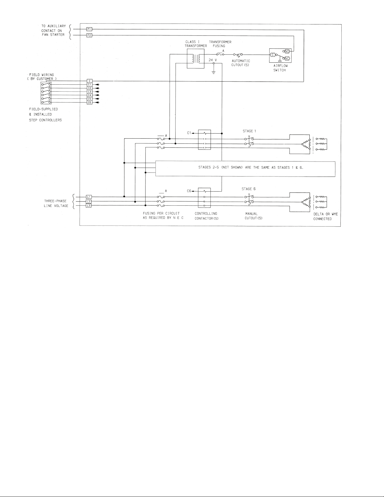
NOTE: All wiring must be copper and must conform to the NEC (National Electrical Code).
Fig. 32 — Typical Electric Heater Wiring Schematic
26

Table 10 — Electric Heater Data
UNIT
HEATER
SIZE
AREA
(sq ft)
CONTROL
39L
03 2.2 3
06 3.7 6
08 5.1 6
10 6.2 6
12 7.3 6
15 10.0 6
18 11.74 6
21 14.21 6
25 17.79 6
NO. OF
STEPS*
HEATER
NOMINAL
COIL FACE
COIL
VELOCITY
kW
9 500 26 25 31 1 35 22 27 1 30 11 14 1 20 14 17 1 20
15 500 44 42 52 1 60 36 45 1 50 18 23 1 25 23 29 1 30
17.2 500 50 48 60 1 60 41 52 1 60 21 26 1 30 26 33 1 35
8 500 14 22 28 1 30 19 24 1 25 10 12 1 20 12 15 1 20
10 500 17 28 35 1 35 24 30 1 35 12 15 1 20 15 19 1 20
17 500 29 47 59 1 60 41 51 1 60 20 26 1 30 26 32 1 35
19.9 500 34 55 69 2 70 48 60 1 60 24 30 1 30 30 38 1 40
27 500 47 75 94 2 100 65 81 2 90 33 41 1 45 41 51 1 60
29.8 500 51 83 104 2 110 72 90 2 90 36 45 1** 45 45 57 1 60
36 500 62 100 125 3†† 150 87 108 2 110 43 54 1** 60 55 68 2** 70
15 500 19 42 52 1 60 36 45 1 50 18 23 1 25 23 29 1 30
25 500 31 69 87 2 90 60 75 2 80 30 38 1 40 38 48 1 50
35 500 44 97 122 3 125 84 105 2 110 42 53 1 60 53 67 2 70
39.9 500 50 111 139 3 150 96 120 3 125 48 60 2 70 61 76 2 80
43.2 500 54 120 150 3 175 104 130 3 150 52 65 2 70 66 82 2 90
51 500 64 142 177 3 200 123 154 3 175 61 77 2 80 78 97 2 100
15 500 15 42 52 1 60 36 45 1 50 18 23 1 25 23 29 1 30
25 500 26 69 87 2 90 60 75 2 80 30 38 1 40 38 48 1 50
39.9 500 41 111 139 3 150 96 120 3 125 48 60 2 70 61 76 2 80
47.3 500 49 131 164 3 175 114 142 3 150 57 71 2 80 72 90 2 90
51.8 500 53 144 180 3 200 125 156 3 175 62 78 2 80 79 98 2 100
59.8 500 62 — — — — — — — — 72 90 2 100 91 114 2 125
19.9 500 17 55 69 2 70 48 60 1 60 24 30 1 30 30 38 1 40
29.8 500 26 83 104 2 110 72 90 2 90 36 45 1 45 45 57 1 60
39.9 500 35 111 139 3 150 96 120 3 125 48 60 2 70 61 76 2 80
43 500 38 119 149 3 150 104 129 3 150 52 65 2 70 65 82 2 90
51.8 500 45 144 180 3 200 125 156 3 175 62 78 2 80 79 98 2 100
72 500 63 — — — — — — — — 87 108 2 110 110 137 3†† 150
19.9 500 13 55 69 2 70 48 60 1 60 24 30 1 30 30 38 1 40
29.8 500 19 83 104 2 110 72 90 2 90 36 45 1 45 45 57 1 60
39.9 500 25 111 139 3 150 96 120 3 125 48 60 2 70 61 76 2 80
45 500 29 125 156 3 175 108 135 3 150 54 68 2 70 68 86 2 90
51.8 500 33 144 180 3 200 125 156 3 175 62 78 2 80 79 98 2 100
65 500 42 — — — — — — — — 78 98 2 100 99 124 3 125
86 500 55 — — — — — — — — 104 129 3 150 131 164 3 175
19.9 500 11 55 69 2 70 48 60 1 60 24 30 1 30 30 38 1 40
25.8 500 14 72 90 2 90 62 78 2 80 31 39 1 40 39 49 1 50
35 500 19 97 122 3 125 84 105 2 110 42 53 1 60 53 67 2 70
45 500 25 125 156 3 175 108 135 3 150 54 68 2 70 68 86 2 90
51.8 500 28 144 180 3 200 125 156 3 175 62 78 2 80 79 98 2 100
78 500 43 — — — — — — — — 94 117 2 125 119 148 3 150
94 500 51 — — — — — — — — 113 141 3 150 143 179 3 200
19.9 500 9 55 69 2 70 48 60 1 60 24 30 1 30 30 38 1 40
25.8 500 12 72 90 2 90 62 78 2 80 31 39 1 40 39 49 1 50
35 500 16 97 122 3 125 84 105 2 110 42 53 1 60 53 67 2 70
45 500 20 125 156 3 175 108 135 3 150 54 68 2 70 68 86 2 90
51.8 500 23 144 180 3 200 125 156 3 175 62 78 2 80 79 98 2 100
79.8 500 36 — — — — — — — — 96 120 3 125 121 152 3 175
92 500 41 — — — — — — — — 111 138 3 150 140 175 3 175
116 500 52 — — — — — — — — 140 175 3 175 — — — —
30 500 11 83 104 2 110 72 90 2 100 36 45 1 50 46 57 1 60
39.9 500 14 111 139 3 150 96 120 3 125 48 60 2 70 61 76 2 80
50 500 18 139 174 3 175 120 151 3 175 60 75 2 80 76 95 2 100
65 500 23 181 226 4 250 157 196 4 200 78 98 2 100 99 124 3 125
79.8 500 29 222 277 5 300 192 240 5 250 96 120 3 125 121 152 3 175
96.5 500 35 268 335 6 350 232 291 5 300 116 145 3 150 14 7 183 4*** 200
110 500 39 — — — — 265 331 6 350 132 166 3 175 167 209 4*** 225
145 500 52 — — — — — — — — 175 218 4*** 225 221 276 5††† 300
(fpm)
TEMP
RISE
(F)
208/3/60 VOLTS 240/3/60 VOLTS 480/3/60 VOLTS 380/3/50 VOLTS
Tot al
MCA†
FLA
LEGEND
ARI — Air Conditioning and Refrigeration Institute
AWG — American Wire Gage
FLA — Full Load Amps
kW — Kilowatts
MCA — Minimum Circuit Amps
MOCP — Maximum Overcurrent Protection
*Standard control steps are listed under the Control Step heading. “Free” additional
steps of control are optionally available when the number of subcircuits exceeds the
standard number of control steps.
†MCA = 1.25 x FLA; for proper wire sizing, refer to Table 310-16 of the NEC.
**2 control steps in this voltage.
††3 control steps in this voltage.
***4 control steps in this voltage.
†††5 control steps in this voltage.
No.
Sub-
Ckt
MOCP
Tot al
FLA
No.
MCA†
Sub-
Ckt
NOTES:
1. Subcircuits are internal heater circuits of 48 amps or less.
2. Electric heat performance is not within the scope of ARI standard 430 certification.
3. To avoid damage due to overheating, minimum face velocity cannot fall below
350 fpm.
MOCP
Tot al
FLA
MCA†
No.
Sub-
Ckt
MOCP
Tot al
FLA
MCA†
No.
Sub-
Ckt
MOCP
27

Table 11 — Field Wiring for Incoming Conductors
Fig. 33 — Fan Discharge Positions, Fans without IGVs
LEGEND
THF — Top Horizontal Front
THR — Top Horizontal Rear
UBF — Upblast Front
UBR — Upblast Rear
Sized for 125% of Heater Load
WIRE SIZE
(AWG or kcmil)
12 16 1/0 120
10 24 2/0 140
8 40 3/0 160
6 52 4/0 184
4 68 250 204
3 80 300 228
2 92 350 248
1 104 400 268
LEGEND
AWG — American Wire Gage
kcmil — Thousand Circular Mils
*Values are based on Table 310-16 of the NEC (National Electrical
Code) for 75 C insulated copper wire. Not more than 3 conductors
in a raceway.
NOTES:
1. Be sure to consider length of wiring run and possible voltage
drops when sizing wires.
2. Field power wiring — Heaters are furnished with a terminal
block sized for incoming copper conductors with 75 C insulation
rated to carry at least 125% of the heater load. However, conductors can be sized to carry 100% of the heater load if the
heater is rated at 50 kW or more, and the heater is controlled by
a cycling device such as a multi-stage thermostat, step controller, or SCR (silicon control rectifier) power controller. Terminal
blocks and knockouts are sized to handle either 100% or 125%
conductors.
LOAD AMPS*
Copper Copper
WIRE SIZE
(AWG or kcmil)
500 304
LOAD AMPS*
Discharge Modification — If field modification of
discharge position is required, 39L fans can be converted (by a
skilled mechanic) to any standard hand and discharge without
any additional parts. (NOTE: This does not apply to a model
change conversion.) All mounting holes are prepunched.
To convert a 39L fan, note the following:
1. Sizes 03-18 without inlet guide vanes (IGVs) — See
Fig. 33. It is not necessary to remove the bearing support
channels from the fan housing.
Sizes 21 and 25 without IGV and 06-25 with IGVs —
See Fig. 34. The “A” frame support must be removed. To
change from upblast to horizontal discharge or from
horizontal to upblast discharge, the bearings must be
relocated to keep the wheel centered in the housing. To
change from upblast front (UBF) to upblast rear (UBR)
or from top horizontal front (THF) to top horizontal rear
(THR) or vice versa, turn the entire fan housing 180 degrees about its base.
2. Inlet guide vane actuators and linkages, where provided,
may be moved to the opposite fan scroll side sheet.
NOTE: The swivel joint must be at the 12 o’clock position on the IGV assembly. (See Fig. 12.) The jackshaft
crankarm, attached to the jackshaft at the “A” frame, will
sit vertically up on all units. Figure 12 illustrates a jackshaft crankarm in the vertical up position.
3. The fan shaft may be driven out and reinstalled to place
the drive pulley on the opposite end.
4. The fan scroll is prepunched for horizontal or vertical discharge to match the support angles at the base of the unit.
5. The motor and motor base may be rotated to place the
motor at the front or rear of the unit. Proper location is
that which results in the longest drive center line distance.
The motor conduit box location may need to be reversed.
6. When hand of fan is changed, it may be necessary to turn
the discharge panel inside-out to fit correctly with the fan
discharge. In this case, remove the existing insulation and
install new duct-liner type insulation on the opposite side
of the discharge panel.
7. Rebalancing of the unit is recommended.
28

START-UP
Fig. 34 — Fan Discharge Positions, Fans with IGVs
LEGEND
THF — Top Horizontal Front
THR — Top Horizontal Rear
UBF — Upblast Front
UBR — Upblast Rear
SQUEEZE-TYPE LOCKING COLLAR
BEARING SETSCREW TORQUE (in.-lb)
BEARING HOLDDOWN BOLT TORGQUE (ft-lb)
Fig. 35 — Fan Shaft Bearing Details
39L UNIT SIZE TORQUE
03,06,08,10,12 70
15,18,21,25 90
BOLT SIZE TORQUE
3
/8-16 30
1
/2-13 63
5
/8-11 100
Check List —
Make a walkway inside unit components to
protect insulation. Remove all construction debris from unit
interior. Remove walkway before starting unit.
FILTERS — Install unit filters in all filter sections.
FANS
1. Check lubrication of fan, motor bearings, and linkages.
a. Note that bearings are shipped completely full of
grease for corrosion protection and may run warm
temporarily on start-up until excess grease has
discharged.
b. Hand-operate all linkages, such as damper and
guide vanes, to check for freedom of movement.
2. Check tightness of bearing setscrews or locking collars
(Fig. 35). Also, check tightness of setscrews on fan
wheels and sheaves.
3. Check tightness of fan shaft bearing mounting.
4. Recheck sheave alignment and belt tension. (Refer to
Fig. 14 and 15.)
5. Hand turn fan to make certain fan wheel does not rub in
housing.
29

6. Check fan speed with a strobe-type tachometer or use the
Fig. 36 — Fan Wheel Rotation
following formula: Obtain the motor rpm from the fan
motor nameplate and read sheave pitch diameters marked
on the fan and motor pulleys, or estimate the pitch diameters by using the pulley outside diameters.
Then:
Motor Rpm x Motor Sheave
Fan Rpm =
Example:
Nameplate Motor
Rpm = 1760 1760
Mtr Sheave Pitch
Diameter = 8.9 in. 9.0 (OD)
Fan Sheave Pitch
Diameter = 12.4 in. 12.5 (OD)
Fan Rpm = 1760 x 8.9
Refer to Table 1, Physical Data for maximum allowable
fan speeds for standard wheels. Excessive fan speed may
result in condensate carryover from cooling coil or fan
motor overload and wheel failure.
7. Check direction of rotation (see Fig. 36). Arrow on drive
side of fan housing indicates correct direction of rotation.
8. Check vibration. If excessive vibration occurs, check for
the following:
a. Variable sheave (if air balance of system has been
accomplished: replace sheave with fixed sheave
for continuous application).
b. Drive misalignment.
c. Mismatched, worn or loose belts.
d. Wheel or sheaves loose on shaft.
e. Loose bearings.
f. Loose mounting bolts.
g. Motor out of balance.
h. Sheaves eccentric or out of balance.
i. Vibration isolators improperly adjusted.
j. Out-of-balance or corroded wheel (rebalance or
replace if necessary).
k. Accumulation of material on wheel (remove
excess material).
COILS
Chilled Water Coil
points are shown in Fig. 17.
— Typical coil vents, drains, and lifting
Pitch Diameter (in.)
Fan Sheave Pitch Diameter (in.)
Actual
Approximate
1760 x 9
= 12.4 12.5
= 1263 Rpm 1267 Rpm
DX Coil
service and installation instructions. Refrigerant operating
charge for unit coil is shown in Table 1.
— Charge refrigerant. Also refer to condensing unit
SERVICE
General
1. Place a suitable walkway to protect floor insulation
whenever entering the fan section.
2. Review Safety Considerations at beginning of these instructions. Good safety habits are important tools when
performing service procedures.
3. To make speed measurements, use a strobe-style tachometer or calculate per Step 6 of Start-Up, Check List.
Fan Motor Replacement
1. Shut off motor power.
2. Disconnect and tag power wires at motor terminals.
3. Loosen motor brace-to-mounting-rail attaching bolts.
Loosen belt tensioning bolts to adjust the motor position
so V-belts can be removed without stretching over
grooves.
4. Mark belt as to position. Remove and set aside belts.
5. Remove motor to motor bracket holddown bolts.
6. Remove motor pulley and set aside.
7. Remove motor.
8. Install new motor. Reassemble by reversing Steps 1-6. Be
sure to reinstall multiple belts in their original position.
Use a complete new set if required. Do not stretch belts
over sheaves. Review the sections on motor and sheave
installation, sheave alignment and belt tensioning discussed previously (Fig. 13-15).
9. Reconnect motor leads and restore power. Check fan for
proper rotation as described in Start-Up, Check List.
Coil Cleaning
DETERGENT — Spray mild detergent solution on coils with
garden-type sprayer. Rinse with fresh water. Check to ensure
condensate line is free. Excess water from cleaning may flood
unit if condensate line is plugged.
STEAM — Remove coil to facilitate cleaning and prevent
damage to unit insulation. See Coil Removal section which
follows.
Winter Shutdown (Chilled Water Coil Only) — It
is recommended that auxiliary drain piping be added to coil
piping if yearly winterizing of coils is anticipated. This auxiliary piping should be located at the highest and lowest point on
the respective header connection for each coil.
ANTIFREEZE METHODS OF COIL PROTECTION
1. Close coil water supply and return valves.
2. Drain coil as follows:
Method I — ‘Break’ flange of coupling at each header
location. Separate flange or coupling connection to facilitate coil draining.
Method II — Open both valves to auxiliary drain piping.
3. After coil is drained, Method I, connect line with a service
valve and union from upper nozzle to an antifreeze reservoir. Connect a self-priming reversible pump between the
low header connection and the reservoir. Method II, make
connection to auxiliary drain valves.
4. Fill reservoir with any inhibited antifreeze acceptable to
code and underwriter authority.
5. Open service valve and circulate solution for 15 minutes;
then check its strength.
30

6. If solution is too weak, add more antifreeze until desired
BOTTOM COIL
BAFFLE
SEE TOP
FLANGE DETAIL
BOTTOM
MOUNTING
FLANGE
TOP FLANGE DETAIL
TOP COIL
BAFFLE
SIDE HEADER
BAFLE
SIDE HAIRPIN
BAFFLE
Fig. 37 — Field-Installed Coils (39LA and LD only)
strength is reached, then circulate solution through coil
for 15 minutes or until concentration is satisfactory.
7. Remove upper line from reservoir to reversible pump.
Drain coil to reservoir and then close service valve.
8. Break union and remove reservoir and its lines.
9. Leave coil flanges or coupling open and auxiliary drain
valves open until spring.
AIR DRYING METHOD OF COIL PROTECTION (Unit
and coil must be level for this method.)
1. Close coil water supply and return main valves.
2. Drain coil as described in procedures for Antifreeze
Methods of Coil Protection.
3. Connect air supply or air blower to inlet header connection and close its drain connection.
4. Circulate air and check for air dryness by holding mirror
in front of open vent in outlet header drain connection.
Mirror will fog if water is still present.
5. Allow coil to stand for a few minutes; repeat step 4 until
coil is dry.
Field-Installed Coils (39LA,LD Only)
When a 39LA or 39LD unit is ordered without the coil, the following loose parts are shipped: (see Fig. 37)
• bottom coil baffle
• side hairpin baffle
• side header baffle
• top coil baffle
These parts should be field-installed onto the coil before
placing the coil into the unit. Once the baffles are installed,
install the coil with the downstream bottom of the coil attached
to the upright mounting flange as shown in Fig. 36. Adjust
the coil and then attach the top coil baffle to the top flange
provided.
Coil Removal
HORIZONTAL UNIT SLANT COIL REMOVAL (39LA
Units)
NOTE: Item numbers are in Fig. 38.
1. Refer to Fig. 4 for service area clearance.
2. Disconnect piping (Item 5).
3. On top panel (Item 3), remove screws located directly
above side panels (Items 2 and 6). Top panels may be removed from unit to provide more workspace, but it is not
required.
4. Remove right side panels (Item 6).
5. If accessory is present, remove accessory side panel
(Item 1) on left side of unit. Detach filter track support
bracket if upstream accessory is a filter.
6. Remove screws from inside baffle (Item 13). Leave baffle
attached to left side panel (Item 2).
7. Remove left side panel (Item 2).
8. Remove condensate baffle (Item 8).
9. Remove coil holddown screws (Items 9 and 11).
10. Remove baffle screws (Item 4) from downstream side of
coil.
11. Tilt coil (Item 10) away from coil support panels (Items 7
and 12) and slowly slide coil out of unit.
12. Replace coil by reversing preceding Steps 1-11.
31

VERTICAL UNIT SLANT COIL REMOVAL (39LD
LEGEND
Fig. 38 — Horizontal Unit Slant Coil Removal (39LA Units — Sizes 03-21)
1— Accessory Side Panel 8—Condensate Baffle
2— Left Side Panel 9—Holddown Screws
3— Top Panels 10 — Coil
4— Baffle Screws 11 — Holddown Screws
5— Piping 12 — Left Support Panel
6— Right Side Panels 13 — Inside Baffle
7— Right Support Panel
Units)
NOTE: Item numbers are in Fig. 39.
1. Refer to Fig. 4 for service area clearance.
2. Disconnect piping (Item 6).
3. Through fan access door (Item 2), remove screws
(Item 3), while holding angle (Item 4) to top of coil side
panels (Item 7). On opposite end of unit, gain access to
similar screws by removing side panels (Item 1).
4. Remove right side panels (Item 7).
NOTE: Support of fan section may be required after re-
moval of side panels (Items 7 and 16).
5. If accessory is present, remove accessory side panel
(Item 15) on left side of unit. Detach filter track support
bracket if upstream accessory is a filter.
6. Remove screws from inside baffle (item 14). Leave baffle
attached to left side panel (Item 16).
7. Remove left side panel (Item 16).
NOTE: Support of fan section may be required after re-
moval of side panels (Items 7 and 16).
8. Remove condensate baffle (Item 9).
9. Remove coil holddown screws (Items 10 and 12).
10. Remove baffle screws (Item 5) from downstream side of
coil.
11. Tilt coil (Item 11) away from coil support panels (Items 8
and 13).
12. Replace coil by reversing preceding Steps 1 - 11.
32

HORIZONTAL OR VERTICAL UNIT — DUAL COIL
LEGEND
Fig. 39 — Vertical Unit Slant Coil Removal (39LD Units — Sizes 03-21)
1— Fan Side Panel 10 — Holddown Screws
2— Fan Access Door 11 — Coil
3— Screws 12 — Holddown Screws
4— Angle 13 — Left Suppor t Panel
5— Baffle Screws 14 — Inside Baffle
6— Piping 15 — Accessory Side Panel
7— Right Side Panels 16 — Left Side Panels
8— Right Support Panel 17 — Rear Panel
9— Condensate Baffle
REMOVAL (39LA,39LD units — size 25) — (NOTE: Item
numbers are in Fig. 40 unless otherwise indicated.)
1. Refer to Fig. 4 for service area requirements.
2. Disconnect piping (Item 5).
3. Horizontal Unit, 39LA — On top panel (Item 3) remove
screws located directly above side panels (Items 2 and 6).
Top panels may be removed from unit to provide more
workspace, but it is not required.
Vertical Unit, 39LD — Through fan access door (Item 2,
Fig. 39), remove screws (Item 3, Fig. 39) holding angle
(Item 4, Fig. 39) to top of coil panels (Item 7, Fig. 39).
Remove rear panel (Item 17, Fig. 39) and remove baffle
angle screws (Item 4) holding top baffle to coil.
4. Remove side panel(s) (Item 6).
NOTE: Vertical units may require support of fan section
after removal of side panels.
5. If accessory is present, remove accessory side panel (Item
1) on left side of unit. Detach filter track support bracket
if upstream accessory is a filter.
6. Remove screws from horizontal baffle (Item 8). Leave
baffle attached to upper condensate pan (Item 9).
7. Remove screws from inside baffles (Item 7). Leave
baffles attached to left side panel (Item 2).
8. Slide coils and header and baffles from unit.
9. Replace coils by reversing proceeding Steps 1-8.
33

HORIZONTAL OR VERTICAL UNIT — VERTICAL COIL
LEGEND
Fig. 40 — Horizontal or Vertical Unit — Dual Coil Removal (39LA,LD Units, Sizes 25)
1— Accessory Side Panel 6—Right Side Panels
2— Left Side Panel 7—Inside Baffle
3— Top Panels 8—Horizontal Baffle
4— Baffle Angle Screws 9—Upper Condensate Pan
5— Piping 10 — Baffle Screw
REMOVAL (39LB,LC,LF,LH Units) — Item numbers are in
Fig. 41 unless otherwise indicated.
1. Refer to Fig. 4 for service area requirements.
2. Disconnect piping (Item 6).
3. Horizontal Unit, 39LB and 39LC — On top panel
(Item 4) remove screws located directly above side panels
(Items 2 and 7). Top panels may be removed from unit to
provide more workspace, but it is not required.
Vertical Unit, 39LF and 39LH — Through fan access
door (Item 2, Fig. 39), remove screws (Item 3, Fig. 39)
holding angle (Item 4, Fig. 39) to top of coil panels
(Item 7, Fig. 39).
Remove rear panel (Item 17, Fig. 39) and remove baffle
angle screws (Item 5) holding top baffle to coil.
4. Remove side panel(s) (Item 7).
NOTE: Vertical units may require support of fan section
after removal of side panels.
5. If accessory is present, remove accessory side panel
(Item 1) on left side of unit. Detach filter track support
bracket if upstream accessory is a filter.
6. Remove screws (Item 8) from inside baffle (Item 3).
Leave baffle attached to left side panel (Item 2).
7. Slide coil and header end baffle from unit.
8. Replace coil by reversing preceding Steps 1-7.
34

Changing Coil Hand
LEGEND
Fig. 41 — Horizontal or Vertical Unit — Vertical Coil Removal (39LB,LC,LF,LH Units)
1— Accessory Side Panel 5—Baffle Angle Screw
2— Left Side Panel 6—Piping
3— Inside Baffles 7—Right Side Panel
4— Top Panels 8—Baffle Screw
NOTE: Electric heat coil hand cannot be changed.
NOTE: The coil cover panel is not part of the coil. Remove
cover panel from end of unit. New holes must be cut in coil
cover panel. Original holes must be plugged and insulated.
New side panels may be necessary when changing coil hand.
NU-FIN COILS — The NuFin coil is airflow direction sensitive, especially when used in dehumidifying applications.
Hydronic versions are counterflow circuited for full gravity
draining when installed level.
Correct installation will result in the typical bottom inlet on
leaving air face and top outlet on entering air face of coil, a
self-venting design. This will ensure cold air contact with cold
water, and warm air with hot water.
Coil repositioning for opposite hand application will compromise one or more of these characteristics. However, there
will be those situations where this may prove acceptable.
As a general rule, a change from counterflow circuiting to
parallel flow for sensible heating and cooling applications will
result in a 5% drop in net capacity per row of coil. In one and
two row heating coils, the actual drop may not be measurable,
thus of insignificant consequence.
It is important that the airflow direction of the NuFin coil be
adhered to when latent cooling is possible. Significant moisture
carryover from the face of the dehumidifying coil will result if
this rule is violated, even at very low face velocities. The same
result is often experienced if after-market fin coatings are
applied.
If a NuFin hydronic coil is installed with correct airflow, but
opposite piping hand, and counterflow is maintained, steps
must be taken to ensure that the coil is continuously vented,
and that the water velocity is maintained to prevent the coil
from air-binding.
Hot or cold areas of the coil face (or otherwise broad temperature differences and stratification) are usually indications
that one or more circuits are air-locked internally. This can
result in coil freeze-up (a condition NOT covered by warranty).
Refrigerant coils may be rotated for opposite hand applications, maintaining the proper airflow direction.
Do not reposition the distributor(s), they will perform equally well in upflow or downflow positions. When soldering
expansion valves to up-feed distributors, use the minimum
satisfactory amount of solder to prevent damaging the valve or
plugging passages.
DIRECT EXPANSION COILS — Rotate the coil in vertical
plane and reinstall. Distributor must be on downstream side of
coil. (Refer to Fig. 42).
CHILLED WATER AND HOT WATER COILS — These coils
can be rotated. If coil is rotated in vertical plane and reinstalled
with counterflow maintained, supply will be at the top of the coil
and return will be at the bottom. Ensure coil is continuously
vented and water velocity is maintained to prevent air binding.
35

Chilled and hot water coils must not be rotated horizon-
DX AND ALL
WATER COILS
STEAM COILS
ONLY
Fig. 42 — Coil Rotation
tally. If coils are rotated horizontally, severe water blow-off
will result.
STEAM INNER DISTRIBUTING TUBE COILS — Rotate
in horizontal plane and reinstall. See Fig. 42.
PIPING — Direct expansion, chilled water, and hot water
coils should always be piped for counterflow. (Fluid should
enter the coil at the leaving-air side.) Steam coils must have the
condensate connection at bottom of coil.
To determine intervals for cleaning coils in contaminated air
operations, pressure taps should be installed across the coils
and checked periodically. Abnormal air pressure drop will indicate a need for cleaning the coils.
Annual maintenance should include:
1. Clean the line strainers.
2. Blow down the dirt leg.
3. Clean and check operation of steam traps.
4. Check operation of control valves.
5. Check the operation of check valves to prevent condensate flowback.
6. Check operation of thermostatic air vents, if used. A float
and thermostatic trap will contain a thermostatic air vent.
When the bellows is ruptured, it will fail closed.
7. Check operation of vacuum breakers.
8. Check operation of the thermal protection devices used
for freeze-up protection.
9. Steam or condensate should not be allowed to remain in
the coil during the off season.This will prevent the formation and build up of acids.
There are additional precautions and control strategies, as
found in various catalogues and in the ASHRAE Fundamentals
Handbook and in the Carrier System Design Guide — Piping
Section, when the entering-air temperature to the coil falls below 35 F. These conditions occur when IDT coils are used for
pre-heat and/or face and bypass applications.
Freeze up protection:
1. Use a strainer in the supply line and the dirt leg ahead of
the trap.
2. Use a vacuum breaker in the return.
3. Do not use overhead returns from the coil. A floodback
can occur.
4. An immersion thermostat to control outdoor-air dampers
and the fan motor is recommended. This control is activated when the steam supply fails or the condensate
temperature drops below a predetermined temperature,
usually 120 F.
5. On low pressure and vacuum systems, the immersion
thermostat may be replaced by a condensate drain with a
thermal element. This element opens and drains the coil
when the condensate temperature drops below 165 F.
Note the thermal condensate drain is limited to 5 psig
pressure. At greater coil pressures they will not open.
In spite of the precautions listed above, a coil may still
freeze up. An oversize capacity coil, at partial load, with a
modulating steam control valve will occasionally freeze.
Freezing occurs in the 20 F to 35 F range of entering-air
temperatures. A better installation would be an undersize coil,
with an on/off control valve with thermostatic control in the
outside air, set at 35 F air temperature, installed downstream of
the first coil; or setting the minimum steam pressure at 5 psig.
Filters
FILTER SECTIONS — See Table 12 for filter data. Filters
are field supplied.
On the size 03 angle filter, a spacer is required on each side
of the filters.
Flat filter section can use 2-in. or 4-in. thick filters. (Size 03
accepts 2-in. filters only.) The flat filter section as shipped accepts 2-in. filters. Remove angle spacer in each filter track to
provide the 4-in. space required to accommodate 4-in. filters.
On all filter sections except size 03, filters are pushed into
the track until they touch the opposite side of the unit. Any remaining space is taken up by the adjustable 2-piece sheet metal
spacer. See Fig. 43 for filter arrangements.
Fan Shaft Bearing Removal
1. Lock open and tag electrical disconnect.
2. Enter through fan section access door or remove panels as
required.
3. Place plywood or other rigid covering on floor to protect
insulation from damage.
4. Block wheel so that it will not pinwheel due to natural
draft through the unit.
5. Loosen motor base to frame bolts. Adjust motor to release belt tension so removal of belts is done without
stretching. Do not stretch belts over sheaves. Damage to
belt can result.
6. Remove bolts on bushing of fan shaft sheave, insert bolts
in jacking hole provided on bushing and slowly jack
bushing from sheave. Then remove bushing on sheave.
7. Loosen bearing setscrews and locking collar.
8. Remove bearing holddown bolts.
9. Remove bearing while observing the following
precautions:
a. Make certain fan shaft surface is not rough or
scored. If so, clean up surface with fine emery
cloth.
b. Add a few drops of oil after cleanup of shaft end.
It should not be necessary to drive a new bearing onto
shaft. If light tapping is needed, do not tap against outer
race.
36

Table 12 — Filter Data
16”
20”
25”
16”
20”
25” 25” 25”
16”
20” 20”
SIZE 21
SIZE 25
Fig. 43 — Filter Arrangement, 2-in. and 4-in. Flat
39L UNIT SIZE 03 06 08 10 12 15 18 21 25
Angle Filter Section
Filter Qty…Size (in.)
Nominal Face Area (sq ft) 5.56 8.89 10.00 11.11 13.33 20.00 26.67 31.11 31.11
Filter Mixing Box Section
Filter Qty…Size (in.)
Nominal Face Area (sq ft) 5.56 8.89 10.00 11.11 13.33 20.00 20.00 23.33 31.11
Flat Filter Section
Filter Qty…Size (in.)*
Nominal Face Area (sq ft) 3.56 5.56 6.94 9.03 10.42 13.33 15.00 18.75 22.50
2…16x25 4…16x20
2…16x25 4…16x20
2…16x16 2…20x20 2…20x25
*Only 2-in. filters are available on size 03.
2…16x20
2…16x25
2…16x20
2…16x25
4…16x25 6…16x20 9…16x20 12…16x20
4…16x25 6…16x20 9…16x20 9…16x20
2…16x25
1…20x25
3…20x25 6…16x20
3…16x20
3…20x20
4…16x20
8…16x25
3…16x20
6…16x25
3…20x25
3…16x25
4…16x20
8…16x25
4…16x20
8…16x25
2…16x20
2…20x20
2…20x25
2…16x25
37

10. Check fan shaft diameter at bearing mount. If worn by
+ .0000
– .001
Fig. 44 — Fan Shaft and Bearing Removal
(Unit without IGVs shown)
Fig. 45 — Fan Cutoff Plate Data (in.)
39L UNIT SIZE
CUTOFF
A
CUTOFF CLEARANCE
B
03 6
5
/
8
7
/
8
06 81
08 103/
8
11/
2
10 93/
4
13/
8
12 93/
4
13/
8
15 12 15/
8
18 153/
4
2
21 15
3
/
4
2
25 201/
2
211/
16
more than .001 in. below nominal, shaft should be replaced.
11. Install new bearing, tighten holddown bolts and then
tighten bearing locking collar and setscrews.
12. Make certain fan wheel does not rub sides of fan housing
after installing new bearings.
13. Recoat fan shaft with a rust inhibitor or grease.
14. Replace sheave and belts. Adjust and align as described
in Installation sections on installing sheaves and V-belts.
15. Remove insulation protection.
16. Replace access panels.
17. Restore electrical power.
Fan and Shaft Removal (Fig. 44) — The fan wheel
and shaft may be removed through inlet side of fan housing.
1. Remove drive belts as described in Fan Shaft Bearing Removal on page 36.
2. Block up fan wheel within housing to prevent dropping
when bearing bolts are removed.
3. Loosen and remove bearing holddown bolts.
4. Remove bearing support channels and inlet ring from one
side.
5. Remove fan shaft and fan wheel from unit.
6. Remove fan shaft from fan wheel.
7. Replace shaft and wheel into fan in the reverse order of
their removal.
8. Inspect bearings and if serviceable, replace on shaft.
9. Align fan wheel and shaft assembly in fan scroll. Check
cutoff location if wheel failure damaged cutoff plate. See
Fig. 45.
10. Tighten bearing holddown bolts, bearing setscrews and
shaft setscrews.
11. Field balancing of shaft and wheel is recommended.
IMPORTANT: Replacement shafts must have a diam-
eter tolerance at bearing mount of nominal.
Carrier-specified parts are recommended.
Lubrication
MOTORS — Lubricate in accordance with nameplate attached to motor or with manufacturer’s recommendations
included with motor.
BEARINGS
Fan Bearings
with suitable bearing grease. Typical lubricants are given in
Table 13.
Inlet Vane and Outlet Damper Bearings
are oil-impregnated. Annually lubricate with a few drops of
nondetergent SAE (Society of Automotive Engineers) 20 oil.
— Lubricate fan bearings every 3 months
— These bearings
Table 13 — Lubricant Data
MANUFACTURER LUBRICANT
Sunoco Prestige 42
Texaco Multipak 2
Texaco Regal AFB-2*
Mobil Mobilplex EP No. 1
*Preferred lubricant because it contains rust and oxi-
dation inhibitors.
38

METRIC CONVERSION CHART
39

Copyright 2004 Carrier Corporation
Manufacturer reserves the right to discontinue, or change at any time, specifications or designs without notice and without incurring obligations.
Catalog No. 533-932 Printed in U.S.A. Form 39L-6SI Pg 40 1110 2-04 Replaces: 39L-5SI
 Loading...