

Page 1

39CCN,CCW
Indoor and Outdoor
Custom Air Handlers
Installation, Start-Up and Service Instructions
CONTENTS
Page
SAFETY CONSIDERATIONS . . . . . . . . . . . . . . . . . . . . . . . 1
INTRODUCTION . . . . . . . . . . . . . . . . . . . . . . . . . . . . . . . . . . .2
PREINSTALLATION. . . . . . . . . . . . . . . . . . . . . . . . . . . . . . 2,3
Receiving and Inspection . . . . . . . . . . . . . . . . . . . . . . . . . . 2
Storage . . . . . . . . . . . . . . . . . . . . . . . . . . . . . . . . . . . . . . . . . . . . 2
Rigging . . . . . . . . . . . . . . . . . . . . . . . . . . . . . . . . . . . . . . . . . . . . 2
• SPLIT UNITS
Clearance Requirements. . . . . . . . . . . . . . . . . . . . . . . . . . . 3
INSTALLATION . . . . . . . . . . . . . . . . . . . . . . . . . . . . . . . . . . 3-6
Air Handler Unit Pad . . . . . . . . . . . . . . . . . . . . . . . . . . . . . . .3
Ceiling Suspended Units. . . . . . . . . . . . . . . . . . . . . . . . . . .3
Roof Curb . . . . . . . . . . . . . . . . . . . . . . . . . . . . . . . . . . . . . . . . .3
Duct/Weather Hood Installation . . . . . . . . . . . . . . . . . . . . 4
Electrical Connections. . . . . . . . . . . . . . . . . . . . . . . . . . . . .4
Coils . . . . . . . . . . . . . . . . . . . . . . . . . . . . . . . . . . . . . . . . . . . . . . . 4
Reassembly of Split Units . . . . . . . . . . . . . . . . . . . . . . . . . 4
Reassembly of Stacked Unit Horizontal Splits. . . . . . 5
Trapping Drains. . . . . . . . . . . . . . . . . . . . . . . . . . . . . . . . . . . .5
Connecting Ducts. . . . . . . . . . . . . . . . . . . . . . . . . . . . . . . . . . 5
Connecting Rain Hoods. . . . . . . . . . . . . . . . . . . . . . . . . . . .5
Electrical Installation . . . . . . . . . . . . . . . . . . . . . . . . . . . . . . 5
START-UP . . . . . . . . . . . . . . . . . . . . . . . . . . . . . . . . . . . . . . . . . 6
Preliminary Inspection . . . . . . . . . . . . . . . . . . . . . . . . . . . 6
Fan Start-Up . . . . . . . . . . . . . . . . . . . . . . . . . . . . . . . . . . . . . 6
SERVICE . . . . . . . . . . . . . . . . . . . . . . . . . . . . . . . . . . . . . . . . 6-9
Monthly . . . . . . . . . . . . . . . . . . . . . . . . . . . . . . . . . . . . . . . . . . . . 6
• RECOMMENDED GREASE
Every Six Months . . . . . . . . . . . . . . . . . . . . . . . . . . . . . . . . . .7
• BELT TENSIONING METHOD
Yearly. . . . . . . . . . . . . . . . . . . . . . . . . . . . . . . . . . . . . . . . . . . . . . 8
INSTALLATION AND STORAGE CHECKLIST. . . 10,11
SAFETY CONSIDERATIONS
Air-handling equipment is designed to provide safe and reliable service when operated within design specifications. To
avoid injury to personnel and damage to equipment or property
when operating this equipment, use good judgment and follow
safe practices as outlined below.
DANGER
NEVER enter an enclosed fan cabinet or reach into a unit
while the fan is running.
LOCK OPEN AND TAG the fan motor power disconnect
switch before working on a fan. Take fuses with you and
note removal on tag. Electric shock can cause personal
injury or death.
LOCK OPEN AND TAG the electric heat coil power disconnect switch before working on or near heaters.
Failure to follow these warnings could lead to personal
injury or death.
WARNING
CHECK the assembly and component weights to be
sure that the rigging equipment can handle them safely.
Note also, the centers of gravity and any specific rigging
instructions.
CHECK for adequate ventilation so that fumes will not
migrate through ductwork to occupied spaces when welding or cutting inside air-handling unit cabinet or plenum.
WHEN STEAM CLEANING COILS be sure that the area
is clear of personnel.
DO NOT attempt to handle access covers and removable
panels on outdoor units when winds are strong or gusting
until you have sufficient help to control them. Make sure
panels are properly secured while repairs are being made to
a unit.
DO NOT remove access panel fasteners until fan is completely stopped. Pressure developed by a moving fan can
cause excessive force against the panel which can injure
personnel.
DO NOT work on dampers until their operators are
disconnected.
BE SURE that fans are properly grounded before working
on them.
Failure to follow these warnings could result in personal
injury or equipment damage.
CAUTION
SECURE drive sheaves with a rope or strap before working on a fan to ensure that rotor cannot free-wheel.
DO NOT restore power to unit until all temporary walkways inside components have been removed.
NEVER pressurize equipment in excess of specified test
pressures.
PROTECT adjacent flammable material when welding or
flame cutting. Use sheet metal or asbestos cloth to contain
sparks. Have a fire extinguisher at hand and ready for
immediate use.
Failure to follow these warnings could result in personal
injury or equipment damage.
Manufacturer reserves the right to discontinue, or change at any time, specifications or designs without notice and without incurring obligations.
Catalog No. 04-53390017-01 Printed in U.S.A. Form 39CC-1SI Pg 1 1-15 Replaces: New
Page 2

INTRODUCTION
The 39CC custom air-handling units are designed for indoor
(39CCN) or outdoor (39CCW) installations. Modular design
allows for heating sections such as hot water coils, steam coil,
or electric heat. Cooling options include chilled water, DX
(direct expansion), or glycol. Filter options include bag, rigid,
HEPA, mini-pleat, vee, and others.
For further information on unit and component identification, contact your Carrier representative for the approved submittal.
PREINSTALLATION
Receiving and Inspection
1. Verify receipt of all parts by comparing items in the shipment with those listed on the bill of lading.
To facilitate inspection, a list of items shipped with the
units is included and attached to the inside access door of
the supply fan section. Among the items generally
shipped loose are the following:
Fan section: Split unit reassembly hardware (nuts, bolts,
caulking); replacement fan belts; lifting lugs.
Filter section: Filters; filter clips
2. Inspect the unit(s) for any damage that may have occurred during shipping.
3. Indicate any problems such as shortage, damage, or
breakage on the carrier’s freight bill and obtain the signature of the driver or carrier’s representative as verification.
4. Immediately report any damage detected after delivery to
the carrier and obtain a concealed damage inspection report upon their inspection of the shipment.
5. If considerable damage has been incurred and the situation is urgent, contact your sales representative for assistance. Please keep a written record of all communications.
Storage — If unit is to be stored for more than 2 weeks pri-
or to installation, note that improper storage will result in seriously reduced equipment reliability. It is likely that an electric
motor or fan that does not experience regular use while being
exposed to normally humid atmospheric conditions will encounter bearing degradation. In addition, the motor’s electrical
insulation may absorb an excessive amount of moisture leading
to the motor winding failing to ground. The following preparations should be followed:
• Minimize condensation in and around the fan and motor
by humidity controls.
• Coat all external machined surfaces with a material to
prevent corrosion.
• Measure and record the motor electrical resistance of
insulation with a Megger meter or a resistance meter.
The insulation resistance = kV rating + 1 Megohom.
Whenever possible, store equipment indoors in a dry area
and protect the fan shaft, bearings and fan wheel from dust and
corrosion.
If outdoor storage is necessary, be sure to close latches on
all access doors to prevent potential water and air leakage. Unit
should be placed on a level surface. Avoid setting the unit directly on water or wet ground. Supports should be placed at
6-ft intervals. Use a tarp or similar weatherproof cover to protect cabinet exterior against dust, dirt, moisture, and corrosion.
Cover the unit from the roof down to the base on each side. Inspect and ventilate each section every 2 weeks to prevent mold/
mildew growth, and to observe overall integrity of the unit.
To protect against excessive vibration and accidental im-
pact, never store other equipment inside or on top of the unit. If
unit must be stored for an extended period, be sure to protect
against bearing damage by manually rotating the fan wheels
and lightly greasing the fan and motor bearings every month.
Rigging — The air-handling unit may be shipped in one of
three ways:
• assembled
• subassemblies or groups of parts
• separate sections
To ensure safe lifting, estimate the unit’s center of gravity,
taking into account that the weight may be unevenly distributed
due to the placement of internal components (for example,
more weight in the coil and fan areas). In case where the unit’s
center of gravity is a concern, please contact your Carrier representative.
Prior to lifting, install the removable lugs shipped loose in
the fan section. Tie downs must be used only to tie the unit to
the truck during shipping. Never attempt to lift the unit using
the tie downs. See Fig. 1.
CHANNEL
LIFTING LUG
TIE DOWN FOR SHIPPING ONLY
a39-4462
Fig. 1 — Lifting Lug
During a lift, all lugs must be used. Spreader bars are re-
quired to prevent damage to the cabinet and protruding components. To distribute the load properly, the tension in each line
must also be adjusted. See Fig. 2.
a39-4463
Fig. 2 — Lifting with Spreader Bars
For smaller units when no lifting lugs are provided, use a
belt-type sling to raise the unit from the base, carefully avoiding door handles, electrical boxes, coil connections, and other
protrusions.
Never lift units or subassemblies without a base by attach-
ing bolts, clevises, pins, hooks, etc. to casing, casing hardware,
flanges, angles, or tabs. Only rig as shown here.
2
Page 3

It is mandatory to use spreader bars for larger units with lifting lugs or slings for smaller units to prevent damage to the
casing of the units by rigging equipment. Only qualified rigging personnel should operate lift equipment.
Units can be lifted with forklifts as long as the forks are
40 inches and the end tips contact the bottom of the intermediate supports of the base rail. Additionally, a fork lift may be
used to lift small subassemblies or individual sections, but the
forks must reach the other side of the base rail. See Fig. 3.
To avoid damaging the air-handling unit, always lift in an
upright position, and never move or lift unit from a sideways or
upside-down position. Use extreme caution when moving an
air-handling unit with a forklift.
a39-4461
FORKS
Fig. 3 — Forklift
installer’s responsibility to secure the unit to the unit pad in accordance with all applicable building and earthquake codes.
After the unit has been installed, the base rail should be inspected for paint damage from chains in the tie down brackets,
use of the lifting lugs and fastening the unit down. This damage
must be repaired by cleaning down to bare metal and applying
two heavy coats of matching paint to stop corrosion and rust.
Ceiling Suspended Units — Ceiling suspended units
must be supported from the base. To fully support the unit, four
or more suspension points are required. The casing is not a support component. The exact number of support points is function of the unit length and weight. Please refer to submittal
drawings for lift locations. The installer is responsible for installing in accordance with applicable building and earthquake
codes. See Fig. 4.
a39-4460
SPLIT UNITS — Split units less than 102 in. may be shipped
loosely assembled. Disassembly is required, with each section
being lifted individually. The “loosely assembled” split sections are affixed using a minimum number of bolts for transit
and cannot be lifted while fastened together. Use all lifting lugs
to avoid unit damage and/or personal injury.
Clearance Requirements — As required by the state,
city or the national electrical code (NEC or CEC), the service
space between the face of any electrical enclosure and wall or
obstruction must be 42 inches minimum.
Sufficient clearances are also needed to open doors and install piping and ductwork. Airflow through the louvers of
hoods cannot be obstructed in any way. The distance between
the louver and any facing wall must be equal to the horizontal
width of the louver.
Space around the unit must allow easy removal of the access panels and parts such as the fan wheels, motors and belt
guards. To facilitate removal of coils, fan shaft, and fan wheel,
allow a minimum clearance equal to the width of the unit on
one side.
INSTALLATION
• The services of qualified field services personnel are
required for safe and proper installation of this equip-
ment.
• Do not operate this unit outside the listed nameplate rat-
ings for flow or static pressure.
• This unit is designed for installation on a level surface or
suspended on a level plane.
• Follow SMACNA (Sheet Metal and Air Conditioning
Contractors’ National Association) guidelines for sup-
ply/return/exhaust duct connections and minimal duct
obstruction clearances.
Air Handler Unit Pad — The foundation and floor
should be level (shim when necessary), rigid, and strong
enough to support the weight of the entire unit. It is the
Fig. 4 — Suspension Mounting
Roof Curb — Roof curbs are shipped either fully welded
or in split sections. Bolt together if roof curb is bolted construction. Follow this procedure to assemble roof curb, if required:
1. Arrange the 4 perimeter sidewalls so that pre-drilled holes
are aligned. Drive bolt each corner securely (bolts provided).
2. Drive bolt the remaining support members using the predrilled holes and provided drive bolts. Turn out the flanges before fastening. See Fig. 5.
SIDEWALL
a39-4464
PRE-DRILLED HOLES
(BOLTS SHIPPED LOOSE)
Fig. 5 — Roof Curb Assembly
3. Line up the assembled curb with the roof openings.
Square up the curb by measuring the diagonal distance
between opposite corners and adjust until the distances
are equal. Level the curb.
4. Install the foam rubber seal strip atop the installed curb.
This provides an airtight seal and isolates the roof from
vibration.
3
Page 4

5. Roof the curb prior to setting the unit. Use standard 2 in. x
4 in. wood nailers (provided), insulate and flash (by others) as required.
6. Check to ensure that curb is level and securely attached to
structure.
7. Check for sufficient height between the unit base and the
roof to allow for drain trapping.
8. Use polyurethane caulking on top of the curb to seal between the unit base and the roof curb.
9. Safely lift the unit into place.
The installer is responsible for installing roof curb in accor-
dance with local building and earthquake codes.
Duct/Weather Hood Installation — Follow
SMACNA and industry guidelines for duct gages, sizing, materials, insulation and supports. Transition to and from units as
required for proper airflow. When installing ductwork or
weather hoods to unit exterior, use gaskets or caulking around
entire perimeter of flange. Align the duct or hood over the
opening. Check for adequate clearance to doors and other
openings. Install the duct of hood using sheet metal screws
through the unit casing. Carefully remove excess caulking, if
required, from around the flange.
Electrical Connections — Follow the latest NEC (Na-
tional Electrical Code) and/or other applicable codes for all
electrical wiring and connections, including grounding.
Nameplate data contains line voltage and minimum ampacity for this unit. Separate line voltage power supply should be
run directly from the building distribution panel to the electrical connection on the unit. Consult wiring diagrams provided
with the unit. Follow NEC and applicable codes for conduit
and wire ratings.
Coils
HEATING COILS (HOT WATER, STEAM) — Heating
coils are constructed of copper tube with corrugated fins. Maximum operating pressure is 150 psig. Coils are provided with
drain and vent connections. Do not block the air vent; this may
result in poor coil performance. Inlet line strainers are recommended to prevent debris from blocking coil tubes or valves.
Common causes of heating coil damage are:
• improper piping installation
• water hammer
• freezing
• control valve chattering
• internal corrosion from chemicals in fluid
• external corrosion from chemicals in the airstream
COOLING COILS (CHILLED WATER, DIRECT EXPAN-
SION, GLYCOL) — Cooling coils are constructed of copper
tube with corrugated fins. Maximum operating pressure is
150 psig. An IAQ 304SS (indoor air quality 304 stainless steel)
condensate drain pan is located under the coil with drain and
vent connections. Do not block the air vent; this may result in
poor coil performance. Inlet line strainers are recommended to
prevent debris from blocking coil tubes or valves.
Common causes of water cooling coil damage are:
• improper piping installation
• water hammer
• freezing
• control valve chattering
• internal corrosion from chemicals in fluid
• external corrosion from chemicals in the air stream
Direct expansion (DX) cooling coils are thermal counter-
flow construction with same end liquid and suction
connections.
Common causes of DX cooling coil damage are:
• improper piping installation
• freezing (due to excessively low pressure)
• internal corrosion
• external corrosion from chemicals in the air stream
Refrigerant distributors are brass, pressure type with copper
distributor tubes factory installed.
Reassembly of Split Units — To prevent air and wa-
ter leaks, all units shipped in sections must be carefully assembled and installed on a proper foundation. Split air units are assembled in one piece in the factory to make sure that all pieces
match and the bolt holes line up, and are then split prior to shipping.
• For proper reassembly, housekeeping pad or roof curb
must be level.
• All nuts, bolts, washers, and caulking required for
assembly of the unit are shipped in the supply fan section.
• Place all sections on level surface.
• Caulk where indicated on both sides of split panel and
roof flanges, and bolt the base together. See Fig. 6.
CAULKING
a39-4465
Fig. 6 — Caulking Split Panel Flanges
• A come-along or hand-operated winch can be used to
tighten the space between unit section.
• Bolt holes may not align as a result of racking during
transit to the job site. In such instances, lift one side with
jack to align holes on wall of the opposite side. After
bolting this wall, remove jack. Then proceed with bolting
the other side, base, floor, and roof. Any racking that is
out of square should realign as the unit settles.
• Check to make sure that all bolts are properly secured.
• Caulk exterior roof seams. See Fig. 7.
4
Page 5
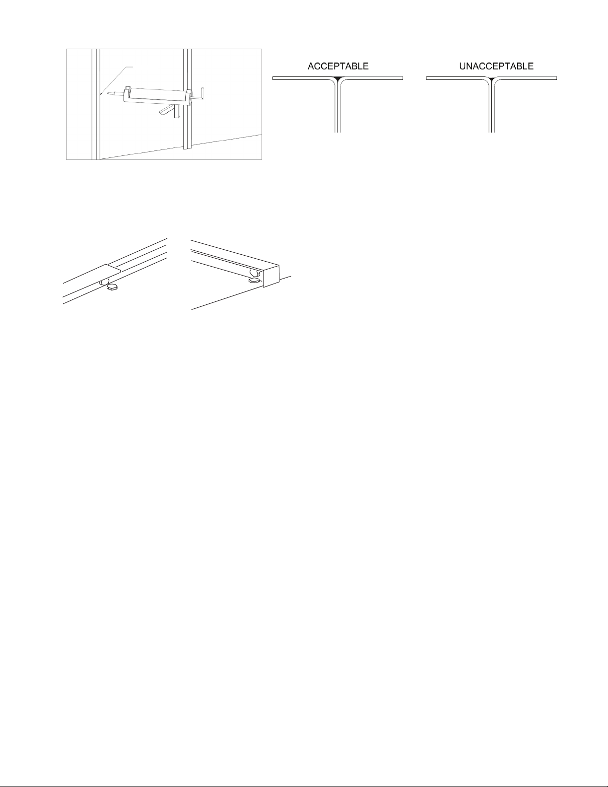
CAULKING
a39-4467
Fig. 7 — Caulking Roof Exterior Seams
• Caulk and bolt standing seam and install the roof cleat.
See Fig. 8.
a39-4466
Fig. 8 — Bolt Standing Seam, Install Roof Cleat
• Check all splits to ensure proper bolting and caulking.
• Check all splits to ensure that all electrical and piping
connections are correct and complete.
Reassembly of Stacked Unit Horizontal
Splits — For a unit is split both vertically and horizontally,
complete the assembly of the lower section first. Next join the
upper sections to the lower sections.
• Caulk underneath clips, behind lifting lugs, and behind
upper base channel.
• Wherever possible, secure base anchor clips in bolt
holes.
• Check all splits to ensure proper bolting and caulking.
• Check all splits to ensure that all electrical and piping
connections are correct and complete.
• If equipment is not properly installed, the cabinet will
leak air under pressure or water may leak into the cabinet
from the split joint.
For units wider than any split section’s airway length, re-
movable lifting lugs are provided along the width of unit. After
closely positioning the split, remove the inner lifting lugs.
During final bolting, a come-along or hand-operated winch can
be used to tighten the space between unit sections.
Trapping Drains — All condensate drain connections
and floor drains must be trapped on the job site by others. Improper drain trapping can cause the drain pan to flood and potentially damage the air-handling unit and surrounding facilities. Improperly trapping a drain can result in a flooded drain
pan and potential water damage to the unit and other building
facilities.
See Fig. 9 for condensate drain trap sizing.
Connecting Ducts — When connecting flanged ducts
directly to the casing, use self-tapping sheet metal screws. For
duct connections to collar-type openings, use s-cleats or overlapping joints. To prevent air leakage and eliminate system performance problems, caulk around all duct connections to form
tight seals.
Connecting Rain Hoods — Be sure to allow adequate
clearance to doors and other openings on the unit. Use sheet
metal screws to fasten the hood or hoods to the casing of the air
handling units. Caulk around the hood flange, then carefully remove any excess caulking.
Electrical Installation — All wiring shall be installed
in accordance with the requirements of the authorities having
jurisdiction. Do not cut holes in the bottom of outdoor units, as
the bottom of the unit has been made waterproof. Both field
wiring and internal wiring diagrams are included in the control
cabinet of the unit. The power requirements are indicated on
the unit nameplate. Where field wiring of the control circuit is
required, take care to size the field wiring for a maximum 10%
voltage drop. The VA rating of the transformer can be
assumed to be the maximum load. The disconnect must be
mounted properly and adequately grounded. All field wiring
outside the electrical enclosure must be rigid or flexible conduit. Reconnect all disconnected wiring on the units that were
split in 2 or more sections for shipment.
Observe the following precautions:
• When connecting a power supply to a three-phase motor,
take care that the three-phase wiring provides the correct
motor and blower rotation.
• Replacement wiring must be equivalent to original wire
size.
• It is recommended that, when interior lighting and convenience outlets are provided, they should be wired to a
separate power supply.
• In all cases the unit must be properly grounded and all
electrical connections should be checked and tightened if
required before starting up the equipment.
• See field-wiring diagram for requirements for shielded or
twisted wire for solid-state devices.
• When cutting holes in the control panel or unit for conduit penetration, make sure conduit penetrations are
sealed to be air and water tight.
• Lock all latches on the electrical and control panels.
5
Page 6
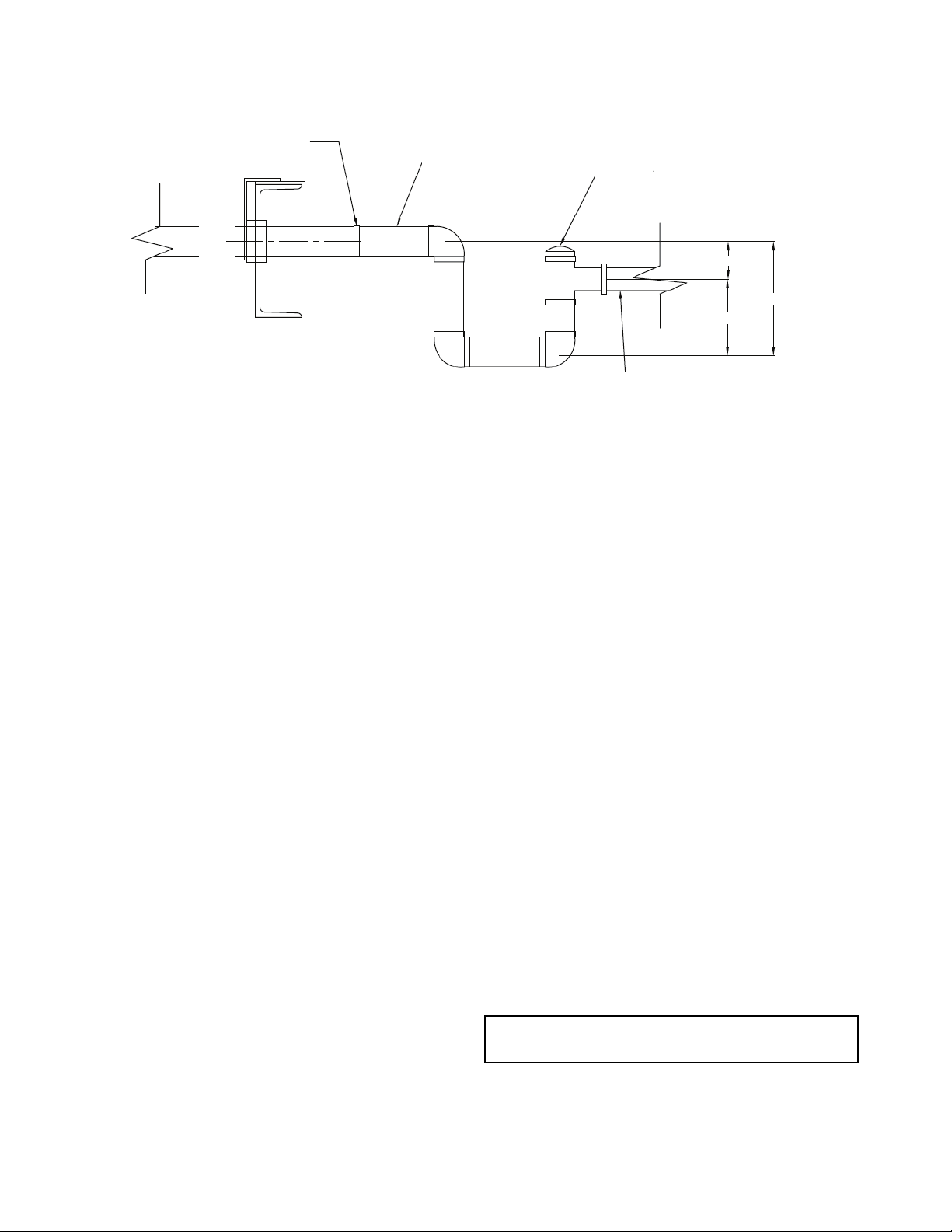
1-¼ IN. MP
(+) STATIC PRESSURE
(BLOW THROUGH COIL)
A—1 in.
B—TSP + 1 in.
C TSP + 2 in.
LEGEND
MP — Male Pipe
TSP — Total Static Pressure (inside drain plenum,
in inches of water)
(-) STATIC PRESSURE
(DRAW THROUGH COIL)
A—TSP + 1 in.
B—
C 1-1/2TSP + 2 in.
SLOPE IN. PER FT MIN.
1
/2TSP + 1 in.
Fig. 9 — Condensate Drain Trap Sizing
1
/8
CLEAN OUT
1
SLOPE IN. PER FT MIN.
/8
A
C
B
a39-4468
START-UP
Preliminary Inspection
1. Disconnect power to unit. Use safety lockouts and label
all disconnects to prevent unintentional powering.
2. Verify all field connections and wiring meet applicable
codes. Verify that power supply connection voltage
matches nameplate rating. Verify all wiring terminals are
tight.
3. Inspect all piping for leak and verify conformance to piping codes.
4. Remove all fan shipping tie-downs and bracing. See the
section Fan Start-Up below.
5. Verify required filters are securely in place before starting
unit.
6. Verify supply duct(s) are free from obstructions.
7. Verify all supply dampers/diffusers area open.
Fan Start-Up
1. Inspect fan and drive assembly (see Fig. 10). Adjust belt
(if applicable) to appropriate tension and alignment.
2. Check fan rotation. Correct by changing wiring if required.
3. Power the fan, measure airflow per AMCA (Air Movement and Control Association) suggested methods, and
compare to nameplate data. Adjust either the VFD (variable frequency drive) or belt-drive sheave to alter the fan
speed to achieve required flow.
4. After proper flow is achieved, verify that the motor amp
draw agrees with the motor nameplate full load amp
rating.
SERVICE
Monthly
1. Check supply air filters and clean or replace as required.
2. Check the cooling coil condensate drain pan for proper
draining and clean if necessary.
3. Fan bearings with grease fittings need to be lubricated.
Bearings that do not have grease fittings are permanently
sealed and do not require lubrication. Check submittal
data for types of bearings used.
a. Fans ship from the factory with fan bearings fac-
tory-lubricated. The fan should be turned off and
locked out to prevent accidental start-up during
lubrication.
b. Verify that the sheaves are secured before servic-
ing the fan.
c. Generally, lubricate fan bearings every 1000 hours.
d. Add grease with manual grease gun until a light
bead of grease appears at the bearing grease seal.
Alternatively, the grease capacity recommenda-
tions in Tables 1 and 2 can help for proper grease
charge.
IMPORTANT: Use only lithium-based grease. See the
section Recommended Grease on page 7.
e. Always lubricate bearings prior to extended shut-
down or storage and rotate shaft monthly.
6
Page 7
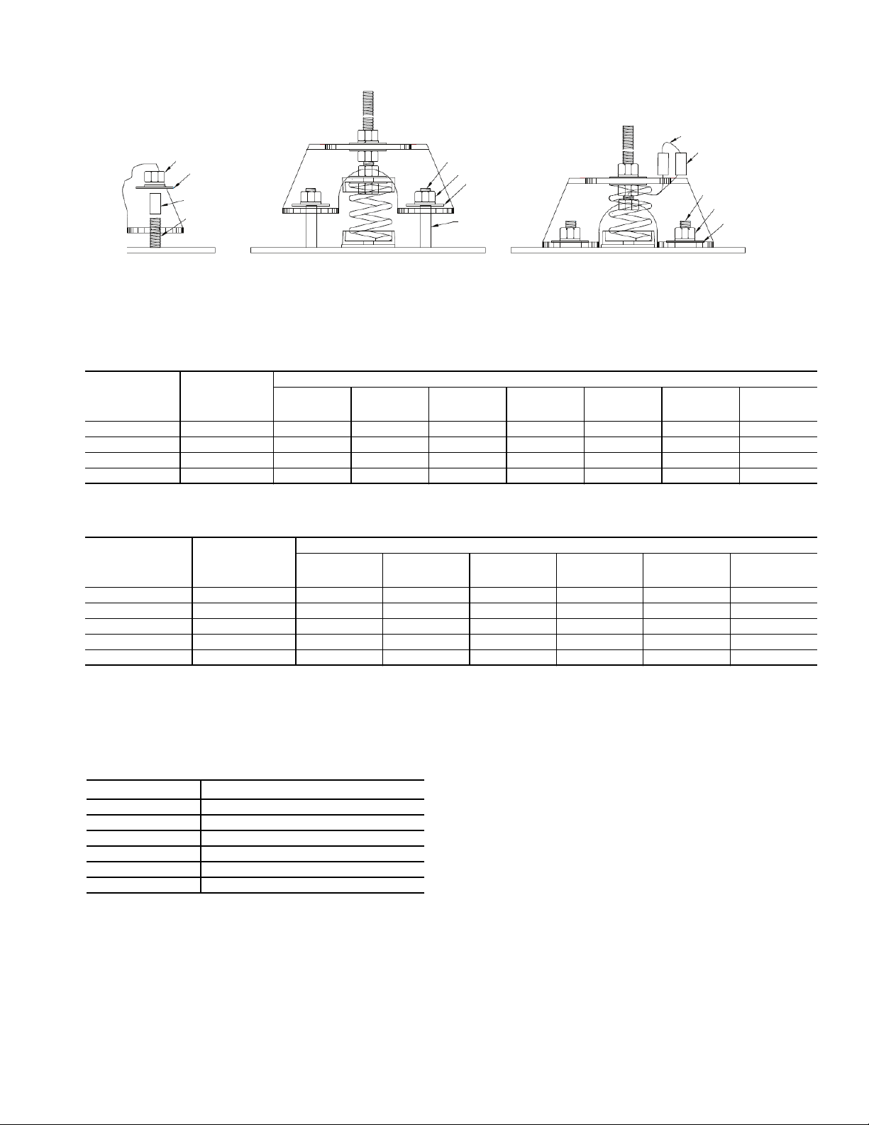
NUTS
SHOULDER
WASHER
TUBE
STUB
STUD
NUT
TUBE ½ IN.
SHOULDER
WASHER
WIRE
TUBE
STUD
NUT
SHOULDER
WASHER
EXPANDED
ASSEMBLY VIEW
OPERATING POSITION
SIDE VIEW
SHIPPING POSITION
SIDE VIEW
a39-4469
Fig. 10 — Fan Assembly
Table 1 — Ball Bearing Lubrication Schedule
SHAFT
DIAMETER
(INCHES)
0.50 to 1.69
1.94 to 2.44
2.56 to 2.94 11/
3.44 to 3.94 3 4 mos. 3 mos. 2 mos. 1 mo. 1 mo. 1 mo. —
APPROX.
GREASE
CAPACITY
(OUNCES)
1
/
2
3
/
4
2
500 1000 1500 2000 2500 3000 3500
6 mos. 6 mos. 5 mos. 3 mos. 3 mos. 2 mos. 2 mos.
6 mos. 5 mos. 4 mos. 2 mos. 2 mos. 1 mo. 1 mo.
5 mos. 4 mos. 3 mos. 2 mos. 1 mo. 1 mo. 1 mo.
FAN SPEED (RPM)
Table 2 — Spherical Roller Bearing Lubrication Schedule
SHAFT
DIAMETER
(INCHES)
1.44 to 1.94
2.19 to 2.69
2.94 to 3.94 2 4.5 mos. 4 mos. 3.5 mos. 2.5 mos. 1.5 mos. —
4.44 to 4.94 4 4 mos. 4 mos. 2.5 mos. 1 mo. — —
5.44 to 5.94 7 4 mos. 2.5 mos. 1.5 mos. — — —
APPROX.
GREASE
CAPACITY
(OUNCES)
1
/
2
3
/
4
500 750 1000 1500 2000 2500
6 mos. 4.5 mos. 4 mos. 4 mos. 3.5 mos. 2.5 mos.
5 mos. 4.5 mos. 4 mos. 2.5 mos. 2.5 mos. 1.5 mos.
FAN SPEED (RPM)
RECOMMENDED GREASE
• NGLI (National Lubricating Grease Institute) no. 2, lithium-based
• Water resistant –20 F to 200 F
Examples are listed below.
BRAND TYPE
Shell Alvania #2
Mobile Mobilux #2
Gulf GulfCrown #2
Keystone 81-EP-2
Texaco Premium RB2
Exxon Unirex #2
Every Six Months
1. Check fans for condition and tension of belts. Replace
cracked, frayed or glazed belt. Re-verify tension after
48 hours and re-tension if required. See the section Belt
Tensioning Method below. Do not over-tighten belts or
bearing damage can occur. Belt should depress its width
when pressed firmly inward at midpoint between pulleys
and should tighten enough to prevent slipping. If motor
pulley shoulder is worn, replace that as well.
2. Check fan and motor bearings for binding, noise, or excessive heat.
3. Check fan wheels for dirt, debris, or grease accumulation.
Clean if required. Do not use caustic or abrasive cleaners
on fan shaft.
BELT TENSIONING METHOD — When installing or re-
placing belts, always use a complete set of new belts. Mixing
old and new belts will result in the premature wear or breakage
of the newer belts.
Refer to label on inside of fan access door for information
on factory-supplied drive.
1. Always adjust the motor position so that V-belts can be
installed without stretching over grooves. Forcing belts
can result in uneven stretching and a mismatched set of
belts.
2. Do not allow belt to bottom out in sheave.
3. Tighten belts by turning motor-adjusting jackscrews.
Turn each jackscrew an equal number of turns.
4. Equalize belt slack so that it is on the same side of belt for
all belts. Failure to do so may result in uneven belt
stretching.
5. Tension new drives at the maximum deflection force
recommended (Table 3).
On current production, the correct tension information is
listed on the fan drive label. For older equipment or units
7
Page 8
with field-modified drives, use the deflection formula in
50 100 150
SPANINCHES
0510 15202530
the following example and the tension data from Table 3.
EXAMPLE:
Given
Belt Span 16 in.
Belt Cross-Section A, Super Belt
Small Sheave PD 5 in.
Deflection =
(Belt Span)
64
Solution
a. From Table 3 find that deflection force for a new
type A, super belt with 5-in. small sheave PD is
8 lb.
b.
16
Deflection =
64
= 1/4 in.
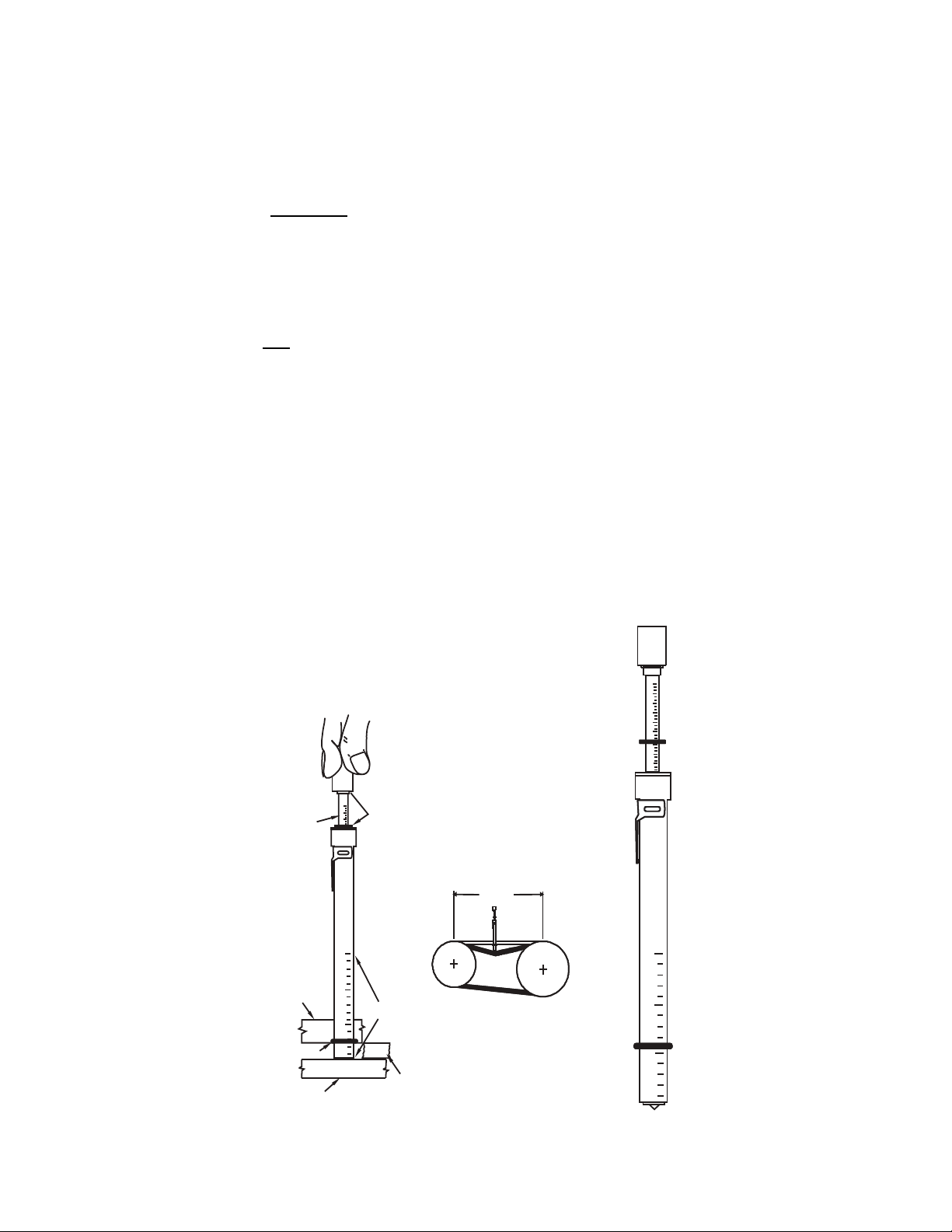
Tension Measurement Procedure
1. Measure the belt span (see Fig. 11).
2. Position bottom of the large O-ring on the span scale at
the measured belt span.
3. Set the small O-ring on the deflection force scale to zero.
4. Place the tension checker squarely on one belt at the center of the belt span. Apply a force on the plunger and perpendicular to the belt span until the bottom of the large Oring is even with the top of the adjacent (next) belt or with
the bottom of a straight edge laid across the outside diameters of the v-belt sheaves.
5. Remove the tension checker and read the force applied
from the bottom of the small O-ring on the deflection
force scale.
6. Compare the force you have applied with the values given in Table 3. The force should be between the “Used
Belt” and “New Belt” values shown. The maximum value is shown for “New Belt” and new belts should be
tensioned at this value to allow for expected tension loss.
“New Belt” tensions should be used at initial installation
and after job start or 1 to 3 minutes of operation. Used
belts should be maintained at the value as indicated in the
chart. “Used Belt” tensions should be used for the 8-hour
and subsequent checks. If the belt span was measured in
centimeters, then use the kilograms of force values for
comparison.
NOTE: The ratio of deflection to belt span is 1:64 in either
unit of measurement.
Whenever possible, jog start for a few revolutions or preferably run drive for approximately 1 to 3 minutes and then retension in accordance with Steps 1-6. Running the drive for a
few revolutions or minutes will help seat the belt(s) in the
groove(s). This relatively early re-tensioning may reduce or
minimize the amount of re-tensioning required in the first 24
hours of drive service. Record information on the label
(Fig. 12) found on the door of the fan section.
Yearly
1. Lightly lubricate dampers and linkages.
2. Inspect both sides of coils for cleanliness. After cleaning,
check again by flashlight from one side to the other by
observing amount of light emission through the coil. Dirt
and debris can collect deep within a multi-row coil. Use
low pressure compressed air to blow through fins or detergent water from clean side to dirty side to clear.
3. Lubricate control valve linkages.
DEFLECTION
FORCE
(LB.)
STRAIGHT
EDGE
LARGE “O” RING
V-BELT
30
5
2
SMALL
20
5
1
“O” RING
BELT
SPAN
50
1
100
SPAN
SPAN SCALE
50
INCHES
ADJACENT
V-BELT
Fig. 11 — Belt Tensioning
SPAN
INCHES
15 20 25 30
10
05
50 100 150
8
Page 9
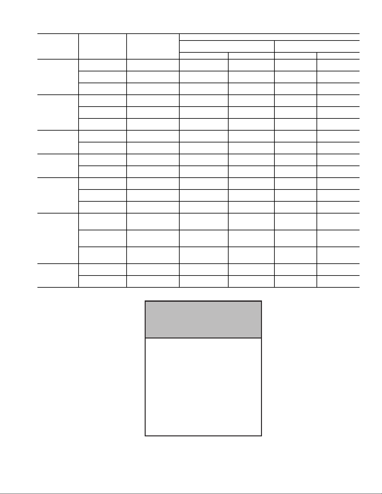
Table 3 — Fan Belt Tension Data
BELT STYLE
A, AX
B, BX
C, CX
D
3V, 3VX
5V, 5VX
8V
SMALLEST
SHEAVE DIAMETER
RANGE (in.)
3.0 - 3.6
3.8 - 4.8
5.0 - 7.0
3.4 - 4.2
4.4 - 5.6
5.8 - 8.6
7.0 - 9.0
9.5 - 16.0
12.0 - 16.0
18.0 - 20.0
2.2 - 2.4
2.65 - 3.65
4.12 - 6.90
4.4 - 6.7
7.1 - 10.9
11.8 - 16.0
12.5 - 17.0
18.0 - 22.4
RPM RANGE
1000-2500
2501-4000
1000-2500
2501-4000
1000-2500
2501-4000
860-2500
2501-4000
860-2500
2501-4000
860-2500
2501-4000
500-1740
1741-3000
500-1740
1741-3000
200-850
851-1500
200-850
851-1500
1000-2500
2501-4000
1000-2500
2501-4000
1000-2500
2501-4000
500-1749
1750-3000
3001-4000
500-1749
1750-3000
3001-4000
500-1749
1750-3000
3001-4000
200-850
851-1500
200-850
851-1500
BELT DEFLECTION FORCE (lb)
SUPER GRIPBELTS AND UNNOTCHED
USED BELT NEW BELT USED BELT NEW BELT
GRIPBANDS
3.7
2.8
4.5
3.8
5.4
4.7
—
—
5.3
4.5
6.3
6.0
11.5
9.4
14.1
12.5
24.9
21.2
30.4
25.6
—
—
3.6
3.0
4.9
4.4
—
—
—
12.7
11.2
15.5
14.6
33.0
26.8
39.6
35.3
5.5
4.2
6.8
5.7
8.0
7.0
—
—
7.9
6.7
9.4
8.9
17.0
13.8
21.0
18.5
37.0
31.3
45.2
38.0
—
—
5.1
4.4
7.3
6.6
—
—
—
18.9
16.7
23.4
21.8
49.3
39.9
59.2
52.7
GRIPNOTCH BELTS AND NOTCHED
GRIPBANDS
4.1
3.4
5.0
4.3
5.7
5.1
4.9
4.2
7.1
6.1
8.5
7.3
14.7
11.9
15.9
14.6
—
—
—
—
3.3
2.9
4.2
3.8
5.3
4.9
10.2
8.8
5.6
14.8
13.7
17.1
16.8
—
—
—
—
6.1
5.0
7.4
6.4
8.4
7.6
7.2
6.2
10.5
9.1
12.6
10.9
21.8
17.5
23.5
21.6
—
—
—
—
4.9
4.3
6.2
5.6
7.9
7.3
15.2
13.2
8.5
22.1
20.1
25.5
25.0
—
—
—
—
NOTICE
TENSION BELTS TO SPECIFICATION
SHOWN ON DRIVE LABEL. OVER
TENSIONING BELTS WILL SEVERELY
REDUCE BELT AND BEARING LIFE.
REPLACEMENT PARTS
BEARINGS
DRIVE _______________________
FREE ________________________
SHAFT _________________________
WHEEL ________________________
INLET CONE ____________________
TO ORDER REPLACEMENT PARTS,
(REPLACEMENT COMPONENTS DIVISION)
Fig. 12 — Fan Section Label
CONTACT: RCD
1-800-443-4410
9
a39-4478
Page 10

INSTALLATION AND STORAGE CHECKLIST
SAFETY
_____
_____
_____
_____
RECEIVING AND INSPECTION
_____
_____
STORAGE
_____
_____
_____
_____
CLEARANCE REQUIREMENTS
_____
_____
LIFTING AND HANDLING
_____
_____
_____
LOCATION CONSIDERATIONS
_____
_____
_____
SPLIT UNIT ASSEMBLY
_____
_____
CONNECTION HOOK-UPS, INCLUDING:
_____
_____
_____
_____
_____
_____
_____
_____
_____
_____
_____
_____
_____
Lockout power supplies before opening access doors.
Prevent wheel rotation during fan servicing.
Replace belt guards or fan safety screen after installation/maintenance is completed.
Replace bolt or lock on “moving” access door.
Inspect for shipping damage.
Compare items on bill of lading with items received.
Store indoors.
Tarp if stored outdoors.
Close all doors if stored outdoors.
Grease fan and rotate shaft monthly while in storage.
Follow NEC requirements for clearance and electrical
controls.
Allow clearance for fan, coil, filter, etc. removal and
replacement.
Lifting facilities are adequate for size and weight of
equipment.
Split sections should be individually handled.
Air handler should only be lifted from removable lifting
lugs on the base channel. (Removable lifting lugs are
stored in the fan section for shipment.)
Support structure is adequately sized for air handler.
Gasketing is placed on roof curbs prior to air handler
installation.
Air handler is secured in accordance with local building
and earthquake codes.
All bolts are in place and tightened.
All exterior seams are caulked.
Duct connections
Power
Water supply
Coil connection
Coil leak tests
Weather hood connection
Humidifiers
Wiring
Actuators
Sensors
Drain pans
Sumps
Other
UNIT FAN
_____
_____
_____
_____
_____
_____
_____
_____
_____
_____
_____
_____
FILTERS
_____
_____
_____
_____
_____
COILS
_____
_____
_____
_____
_____
_____
_____
_____
_____
EVAPORATIVE COOLING PACKAGES
_____
_____
_____
_____
_____
_____
_____
_____
_____
Visually inspect wheel and fan rotation.
Inertia base is fitted.
Shipping tie downs are removed.
Seismic restraints are set up.
There are no impairments to “free” isolation.
The flex power line to fan motor does not interfere with
isolation.
Check belt tension.
Check flex connection on fan.
Check VAV (variable air volume) devices and VAV
actuators.
Bearings on fan are free of noise and operate freely;
locking collars are set.
Verify that lubrication lines are attached and that bearings have been factory-lubricated.
Check motor for nameplate vs. actual amps/voltage
Verify that filters are installed properly.
Verify that all seals are in place.
Verify that doors close properly.
Check air filter gages for operation.
Verify that all pressure tips are in place and not blocked.
Check coils for visible damage and repair.
Verify that coil blank-offs are in place and sealed.
Verify that piping penetrations through cabinet wall are
sealed properly.
Verify that piping to coils is completed.
Confirm that piping has been tested.
Clean drain pans.
Check that drain connection is clear.
Verify that drain traps are installed.
Prime traps.
Connections to unit are completed.
Float system is checked for operation.
Sump pump is hooked to power.
EVAP media is checked for damage.
All blank-offs are in place.
Water treatment devices are installed (if applicable).
The system has been filled with water and test-run for
leakage and high/low water shutoff.
The system has been run for 24 hours and the water
changed.
All controls as specified in submittals are in place and
tested.
10
Page 11

ELIMINATORS AND DAMPERS
_____
_____
_____
_____
_____
_____
GENERAL
_____
_____
_____
_____
_____
AFTER FAN START-UP: After 8 hours and 48 hours of fan
operation, shut down fan, lockout power, and check the
following:
_____
_____
_____
_____
_____
Equipment has been visually inspected for damage;
damaged blades/linkage repaired.
Check that low-leak damper edge and blade seals are in
place and not loose.
Manually operate each damper through cycle to verify
operation and complete closure.
Actuators are installed.
Actuators have been hand-operated through cycle to
ensure there is no over-torquing.
Actuators have been power-operated through cycle to
verify operation.
Entire cabinet has been visually checked and repairs
made if necessary.
Access doors have been checked for free movement
and complete closure.
All seams are sealed.
Verify that there are no air leaks with running fan.
Check interior of unit for loose or damaged insulation
and make repairs if necessary.
Thrust restraints
Set screws and hold downs
Drive coupling alignments
Belt drive
Bearing housing temperature
SIGNATURE: ___________________________________________________ DATE: _______________________________________
11
Page 12

© Carrier Corporation 2015
Manufacturer reserves the right to discontinue, or change at any time, specifications or designs without notice and without incurring obligations.
Catalog No. 04-53390017-01 Printed in U.S.A. Form 39CC-1SI Pg 12 1-15 Replaces: New
 Loading...