

Carrier 38TZA048 SERIES300, 38TZA060 SERIES330, 38TZA060 SERIES300, 38TZA024 SERIES330, 38TZA030 SERIES300 Installation Guide
...
HEATUNG & COOUNG
%isitx__ _.carrier.com
Installation and Start-Up instructions
NOTE: Read the entire instruction manual before starting the
installation.
This symbol --> indicates a change since the last issue.
SAFETY CONSIDERATIONS
Improper installation, adjustment, alteration, service, maintenance,
or use can cause explosion, fire, electrical shock, or other
conditions which may cause death, personal injury, or property
damage. Consult a qualified installer, service agency, or your
distributor or branch for information or assistance. The qualified
installer or agency must use fi_ctory=authorized kits or accessories
when modifying this product. Refkr to the individual instructions
packaged with the kits or accessories when installing.
Follow all safety codes. Wear safety glasses, protective clothing,
and work gloves. Use quenching cloth fbr brazing operations.
Have fire extinguisher available. Read these instructions thor=
oughly and fbllow all warnings or cautions included in literature
and attached to the unit. Consuh local building codes and National
Electrical (?ode (NEC) tbr special requirements.
Recognize safety informatiom This is the safety-alert symbol z_.
When you see this symbol on the unit and in instructions or
manuals, be alert to the potential for personal injury.
Understand these signal words; DANGER, WARNING, and
CAUTION. These words are used with the safety=alert symbol.
DANGER identifies the most serious hazards which will result in
severe personal injury or death. WARNING signifies hazards
which could result in personal inju V or death. CAUTION is used
to identify unsaf_ practices which would result in minor personal
injury or product and property damage. NOTE is used to highlight
suggestions which will result in enhanced instalhion, reliability, or
operation.
Befbre installing, modil_-ing, or servicing system, main elec-
trical disconnect switch must be in the OFF position. There
may be more than 1 disconnect switch. Lock out and tag
switch with a suitable warning label. Electrical shock can
cause personal injury or death.
Puron_R: systems operate at higher pressures than standard
R=22 systems. To avoid danmge to the unit or possible
personal inju_', do not use R-22 sen-ice equipment or
components on Puronta equipment.
mNSTALLATmON RECOMMENDATBONS
NOTE: In some cases noise in the living area has been traced to
gas pulsations fi'om improper installation of equipment
1. Locate unit away from windows, patios, decks, etc. where unit
operation sound may disturb customer.
2. Ensure that vapor and liquid robe diameters are appropriate for
unit capacity.
38TPA, TZA, TXA, TSA
11, 12, 13, t4 SEER SpMit-System
Air Conditioners with Puron®
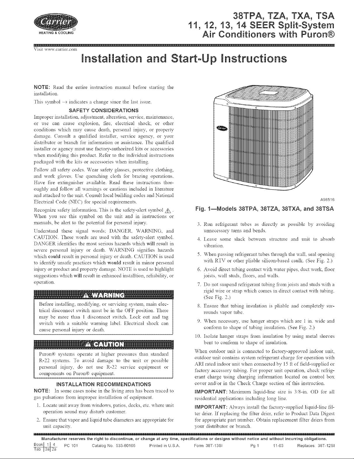
A98516
Fig. 1--Models 38TPA, 38TZA, 38TXA, and 38TSA
3 Run refrigerant tubes as directly as possible by avoiding
unnecessary rams and bends
4. Leave some slack between structure and unit to absorb
vibration.
5. When passing refi'igerant robes through the wall, seal opening
with RTV or other pliable silicon-based caulk. (See Fig. 2.)
6. Avoid direct robing contact with water pipes, duct work, floor
joists, wall studs, floors, and walls.
7. Do not suspend refrigerant tubing fi'om joists and studs with a
rigid wire or strap which comes in direct contact with tubing.
(See Fig. 2.)
8 Ensure that robing insulation is pliable and completely sur-
rounds vapor mbe.
9. When necessary, use hanger snaps which are 1 in. wide and
confbnn to shape of robing insulation. (See Fig. 2.)
10. Isolate hanger straps from insulation by using metal sleeves
bent to confbrm to shape of insulation.
When outdoor unit is connected to factory-approved indoor unit,
outdoor unit contains system refrigerant charge fbr operation with
ARI rated indoor unit when connected by 15 [_of field-supplied or
factor?" accessory tubing. For proper unit operation, check refrig-
erant charge using charging in_bnnation located on control box
cover and/or in the Check Charge section of this instructiom
IMPORTANT: Maximum liquid-line size is 3/8-im OD for all
residential applications including long line.
IMPORTANT: Always install the fhctoo,-supplied liquid-line fil-
ter drier. If replacing the filter drier, refer to Product Data Digest
for appropriate part number. Obtain replacement filter driers from
your distributor or branch.
Manufacturer reserves the right to discontinue, or change at any time, specifications or designs without notice and without insurring obligations,
PC 101 Catalog No 533-80105 Printed in U.S.A. Form 38T-13SI Pg 1 1%03 Replaces: 38%12SI
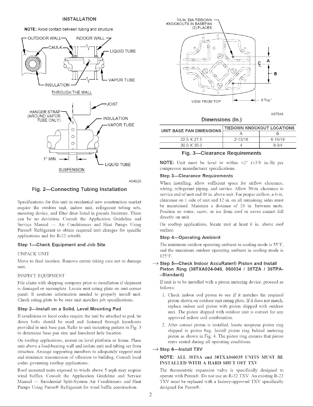
INSTALLATION
NOTE: Avoid contact between tubing and structure
_SULATION___VAPOR TUBE
THROUGH THE WALL
3/8-1N. DIA TIEDOWN
KNOCKOUTS IN BASEPAN
121 PLACES
VIEW FROM TOP
l
A
3/16"
HANGER STRAP-- X
(AROUND VAPOR_ --
,>__IN SULATION
TUBE_,
_,/--JOIST
VAPOR TUBE
r' MIN
SUSPENSION
Fig. 2--Connecting Tub{rig InstNtation
Specifications %1" this unit in residential new construction market
require d_e outdoor unit, indoor unit, refrigerant robing sets,
metering device, and tilter drier listed in presale literature The*e
can be no deviation, Consult the Application Guideline and
So*vice Manual Air Conditioners and Heat Pumps Using
Puron® Refl'igerant to obtain required unit changes for specific
applications and for R-22 retrofit.
Step 1--Check Equipment and Job Site
L NPACK LNIT
Move to final location Remove carton taking care not to damage
unit,
INSPECT EQUIPMENT
File claim with shipping company prior to installation if shipment
is damaged or incomplete Locate unit rating plate on unit corner
panel It contains information needed to properly install unit
(hock rating plate to be sure unit matches job specifications.
Step 2--Install on a Solid, Level Mounting Pad
If conditions or tocal codes require the unit be attached to pad, tie
down bolts should be used and fastened through knockouts
provided in unit base pan. Refer to unit mounting pattern in Fig 3
to detem_ine base pan size and knockout hole location.
On rooftop applications, mount or* level plaffbrm or fi'ame. Place
unit above a load-bearing wall and isolate unit and robing set fiom
structure. Arrange supporting members to adequately support unit
and minimize transmission of vibration to building. Consult local
codes governing rooftop applications.
Roof mounted units exposed to winds above 5 mph may require
wind baffles. Consult the Application Guideline and Service
Manual Residential SplitoSystem Air Conditioners and Heat
Pumps Using Puron® Refrigerant for wind baffle construction.
LIQUID TUBE
A94028
Dimensions (In.)
UNIT BASE PAN DBMENSBONS
22.5 X 27.5 2-13/16 6-15116
30.0 X 35.0 4 9-3/4
TiEDOWN KNOCKOUT LOCATIONS
Fig. 8--Clearance Requirements
NOTE: Unit must be level to within ÷2 ° (÷3/8 inift) per
compressor manufhcturer specifications.
Step a--Clearance Requirements
When installing, allow sufficient space for airflow clearance,
wiring, refi'igerant piping, and service. Allow 30oin. clearance m
service end of unit and 48 in. above unit. For proper airflow, a 6oin.
clearance on 1 side of unit and 12 in. on all remaining sides must
be maintained. Maintain a distance of 24 in. between units.
Position so water, snow, or ice from roof or eaves cannot fall
directly on unit.
On rooftop applications, locate unit at least 6 in. above roof
surface.
Step 4_Operating Ambient
)"he minimum outdoor operating ambient in cooling mode is 55°F,
and the maximum outdoor operating ambient in cooling mode is
125°F.
--> Step 5--Cheek indoor AceuRater® Piston and Install
Piston Ring {38TXA024o048, 060034 / 38TZA / 38TPA=
=Standard)
If'unit is to be installed with a piston metering device, proceed as
follows:
1. Check indoor coil piston to see if it matches the required
piston shown or* outdoor unit rating plate. If it does not match,
replace indoor coil piston with piston shipped with outdoor
unit. The piston shipped with outdoor unit is correct fbr any
approved indoor coil combination.
2. After correct piston is installed, locate neoprene piston ring
shipped in piston bag. Install piston ring behind metering
piston as shown in Fig. 4. The piston ring ensures that piston
stays seated during all operating conditions.
---> Step g--Install TXV
NOT[[: ALL 38TSA and 38TXA060035 [NH'S MIST BE
INSTALLED WITH A HARD SH[T OFF TXV
The thermostatic expansion valve is specifically designed to
operate with Puron:_. Do not use an Ro22 TXV. An existing Ro22
TXV must be replaced with a factou-approved TXV specifically
designed for Purona;.
A97548
NOTE: FK4 and FC4 _hn coils are equipped with an R=22 TXV
If an FK4 o1"an FC4 fire coil is used with a Puron;R; air conditioner,
the R=22 TXV must be replaced with a Puron® TXV or with the
accessory piston body kit and piston shipped with outdoor unit.
STRAINER
TXV, marked "IN" to liquid line Avoid excessive heat which
could damage valve.
6 Install vapor elbow with equalizer adapter to suction tube of
line set and suction connection to indoor coil. Adapter has a
1/4-in. male connector fbr attaching equalizer tube
7 Connect equalizer robe of TXV to li4-in equalizer fitting on
vapor line adapter.
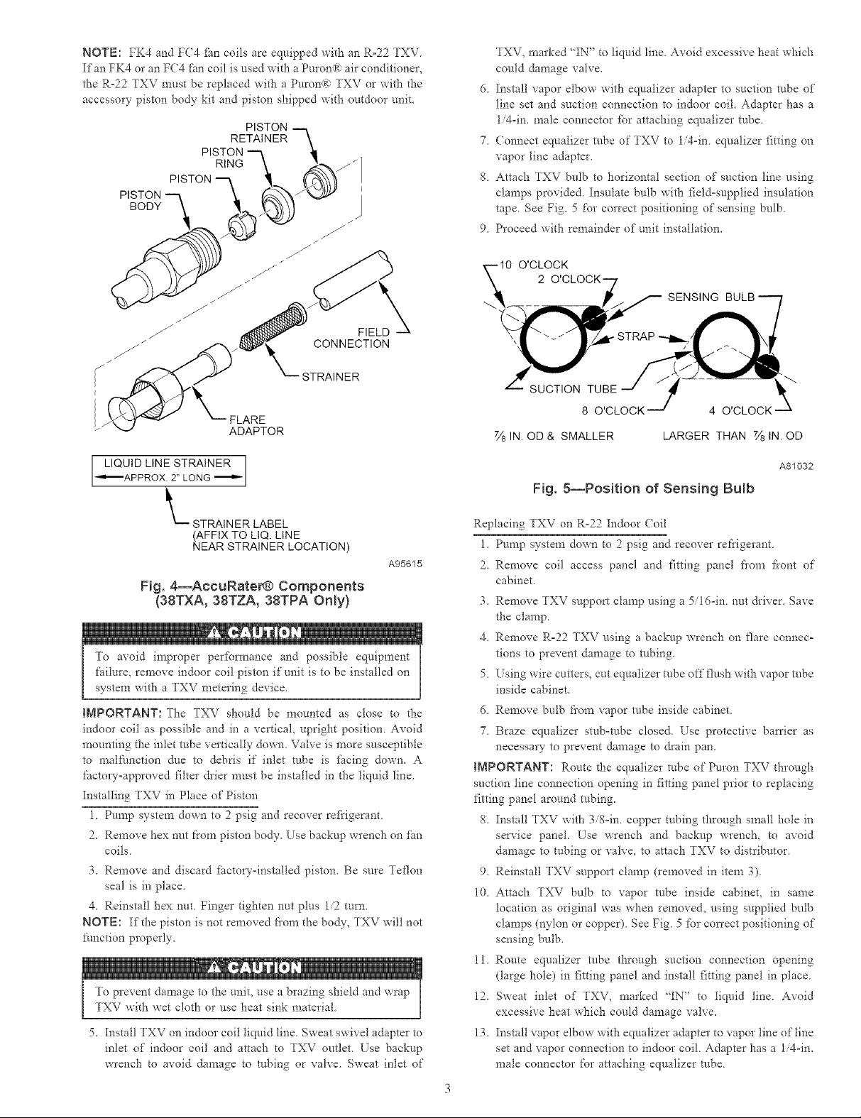
g Attach TXV bulb to horizontal section of suction line using
clamps provided Insulate bulb with field=supplied insulation
tape See Fig. 5 for correct positioning of sensing bulb.
9 Proceed with remainder of unit installation.
SENSING
FLARE
ADAPTOR
LIQUID LINE STRAINER
_APPROX 2" LONG
L STRAINER LABEL
(AFFIX TO LIQ. LINE
NEAR STRAINER LOCATION)
A95615
Fig. 4--AccuRateNg) Components
(38TXA, 38TZA, 38TPA Only)
To avoid improper per%finance and possible equipment
failme, remove indoor coil piston if"unit is to be installed on
system with a TXV metering device,
IMPORTANT: The TXV should be mounted as close to the
indoor coil as possible and in a vertical, upright position Avoid
mounting the inlet tube vertically down. Valve is more susceptible
to malfunction dne to debris if inlet tube is fi_cing down. A
factory=approved filter drier must be installed in the liquid line.
Installing TXV in Place of Piston
1. Pump system down to 2 psig and recover refi'igerant.
2. Remove hex nut from piston body Use backup wrench on _n
coils
3. Remove and discard _Sctory=installed piston. Be sure Teflon
seal is in place.
4. Reinstall hex nut. Finger tighten nut plus 1/2 turn.
NOTE: If the piston is not removed flora the body, TXV will not
function properly.
t . * j
To prevent damage to the unit, use a brazing shield and wrap
TXV with wet cloth or use heat sink material
5. Install TXV on indoor coil liquid line. Sweat swivel adapter to
inlet of indoor coil and attach to TXV outlet Use backup
wrench to avoid damage to robing or valve Sweat inlet of
4 O'CLOCK
7/8IN. OD & SMALLER LARGER THAN 7/8IN. OD
A81032
Fig. g--Position of Sensing Bulb
Replacing TXV on R-22 Indoor Coil
1 Pump system down to 2 psig and recover refrigerant
2 Remove coil access panel and fitting panel flora _?ont of'
cabinet.
3. Remove TXV support clamp using a 5/16-in. nut &iver. Save
the clamp.
4. Remove R=22 TXV using a baclcup wrench on flare connec-
tions to prevent damage to tnbing.
5. Using wire cutters, cut equalizer robe offflush with vapor robe
inside cabinet.
6. Remove bulb fi'om vapor robe inside cabinet.
7. Braze equalizer stub-robe closed. Use protective battier as
necessary to prevent damage to drain pan.
IMPORTANT: Route d-_e equalizer tube of Puron TXV through
suction line connection opening in fitting panel prior to replacing
fitting panel around tubing.
8. Install TXV with 3/8=in. copper tubing through small hole in
service panel. Use wrench and backup wrench, to avoid
damage to tubing or valve, to attach TXV to distributor.
9. Reinstall TXV suppolq _ clamp (removed in item 3).
10. Attach TXV bulb to vapor robe inside cabinet, in same
location as original was when removed, using supplied bulb
clamps (nylon or copper). See Fig. 5 for con'ect positioning of
sensing bulb.
l
11. Route equalizer robe through suction connection opening
(large hole) in fitting panel and install fitting panel in place.
12. Sweat inlet of TXV, marked "IN" to liquid line. Avoid
excessive heat which could damage valve.
13. Install vapor elbow with equalizer adapter to vapor line of line
set and vapor connection to indoor coil. Adapter has a 1/4-in.
male connector for attaching equalizer robe.
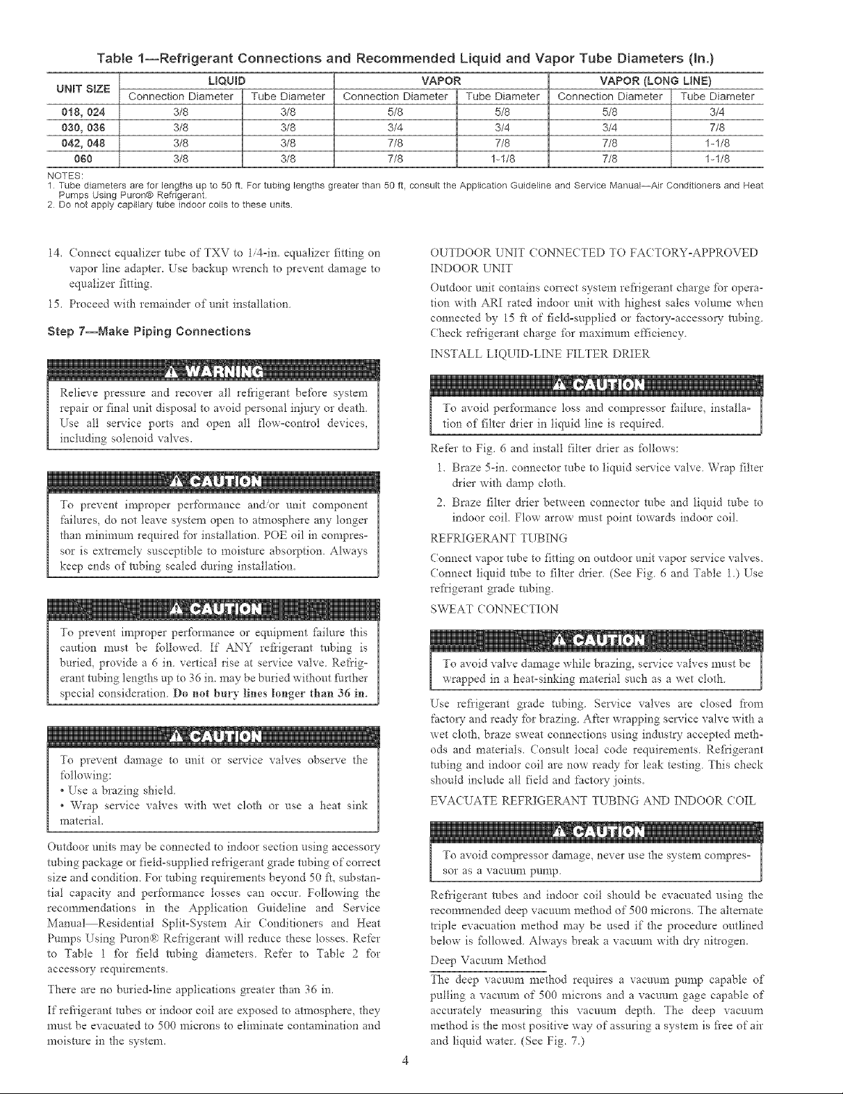
Table 1--Refrigerant Connections and Recommended Liquid and Va
UNIT SIZE
0t8, 024 3/8 3/8 5/8 5/8
030, 036 3/8 3/8 3/4 3/4
042, 048 3/8 3/8 7/8 7/8
060 3/8 3/8 7/8 1-1/8
NOTES:
1 Tube diameters are for lengths up to 50 ft. For tubing lengths greater than 50 ft, consult the Application Guideline and Service Manual--Air Conditioners and Heat
Pumps Using Puron® Refrigerant
2 Do not apply capillary tube indoor coils to these units
Connection Diameter Tube Diameter Connection Diameter Tube Diameter
LIQUID VAPOR
_or Tube Diameters (In.)
VAPOR (LONG LINt=)
Connection Diameter Tube Diameter
5/8 3/4
3/4 7/8
7/8 1-1/8
7/8 1-1/8
14. (onnect equalizer robe of TXV to 1i4qn. equalizer fitting on
vapor line adapter. Use backnp wrench to prevent damage to
equalizer fitting.
15. Proceed with remainder of unit installation
Step 7--Make Piping Connections
Relieve pressure and recover all refrigerant be%re system
repair or final unit disposal to avoid personal inju_ or death.
Use all smwice ports and open all flow°contIol devices,
including solenoid valves.
To prevent improper perfbm_ance and/or unit component
failures, do not leave system open to atmosphere any longer
than minimum required for installation POE oil in compres=
sot is extremely susceptible to moisture absorption. Always
keep ends of robing sealed during installation.
To prevent improper per_:brmance or equipment fitilure this
caution must be fPllowed. If ANY refrigerant robing is
buried, provide a 6 in. vertical rise at service valve. Refrig=
erant robing lengths up to 36 in. may be buried without further
special consideration Do not bury lines longer than 36 in.
To prevent damage to unit or service valves observe the
following:
*Use a brazing shield
* Wrap service valves with wet cloth or use a heat sink
material.
Outdoor units may be connected to indoor section using accesso_-
tubing package or field-supplied refrigerant grade robing of correct
size and condition. For robing requirements beyond 50 ft, substan=
tia] capacity and performance losses can occur Following the
recommendations in the Application Guideline and Service
Manual Residential Split=System Air (onditioners and Heat
Pumps Using Puron(_-': Refrigerant will reduce these losses. Refer
to Table 1 _br field robing diameters. Refer to Table 2 for
accessory requirements.
There are no buried-line applications greater than 36 in.
If refi'igerant robes or indoor coil are exposed to atmosphere, they
must be evacuated to 500 microns to eliminate contamination and
moisture in the system.
OUTDOOR UNIT CONNECTED TO FA( TORY-APPROVED
INDOOR UNIT
Outdoor unit contains con'ect system re_:i'igerant charge _br opera-
tion with ARI rated indoor unit with highest sales volume when
connected by 15 ft of []eld-supplied or _ctory-accesso_- robing.
(beck refrigerant charge _br maxinmm efficiency
INSTALL LIQUID-LINE FILTER DRIER
To avoid per%finance loss and compressor _ilure, installa=
tion of filter &ier in liquid line is required
Re_r to Fig. 6 and install filter drier as _bllows:
1. Braze 5-in. connector tube to liquid service valve Wrap filter
&ier with damp cloth
2. Braze filter drier between connector robe and liquid tube to
indoor coil. Flow arrow must point towards indoor coil.
REFRIGERANT TUBING
(onnect vapor tube to fitting on outdoor unit vapor service valves.
(onnect liquid robe to filter drier (See Fig 6 and Table 1.) Use
refrigerant grade robing.
SWEAT CONNECTION
To avoid valve damage while brazing, service valves must be
wrapped in a heat-sinking mate*ial such as a wet cloth
Use refiigerant grade robing Service valves are closed from
facto W and ready for brazing Aker wrapping service valve with a
wet cloth, braze sweat connections using industry accepted meth-
ods and materials. Consult local code requirements. Refrigerant
robing and indoor coil are now ready for leak testing. This check
should include all field and facto W joints.
EVACUATE REFRIGERANT TUBING AND INDOOR COIL
a
To avoid compressor damage, never use the system compres°
sot as a vacmlm pump
Refiigerant robes and indoor coil should be evacuated _lsing the
recommended deep vacuum method of 500 microns. The alternate
triple evacuation method may be used if"the procedure outlined
below is _bllowed Always break a vacuum with dW nitlogen.
Deep Vacuum Method
The deep vacuum method requires a vacuum pump capable of
pulling a vacuum of 500 microns and a vacuum gage capable of
accurately measuring this vacuum depth, The deep vacuum
method is the most positive way of assuring a system is _:i'eeof air
and liquid water. (See Fig. 7,)
 Loading...