

Page 1
HEATING & COOLING
Heat Pumps—Outdoor Section
Installation and Start-Up Instructions
NOTE: Read entire instruction before beginning installation.
SAFETY CONSIDERATIONS
Improper installation, adjustment, alteration, service, maintenance,
or use can cause explosion, fire, electrical shock or other condi
tions which may cause personal injury or property damage.
Consult a qualified installer, service agency, or your distributor or
branch for information or assistance. The qualified installer or
agency must use factory-authorized kits or accessories when
modifying this product. Refer to the individual instructions pack
aged with the kits or accessories when installing.
Follow all safety codes. Wear safety glasses and work gloves. Use
quenching cloth for brazing operations. Have fire extinguisher
available. Read these instructions thoroughly and follow all
warning or cautions attached to the unit. Consult local building
codes and National Electrical Code (NEC) for special require
ments.
It is important to recognize safety information. This is the
safety-alert symbol ^ . When you see this symbol on the unit and
in instructions or manuals, be alert to the potential for personal
injury.
Understand the signal word— DANGER, WARNING, or CAU
TION. These words are used with the safety- alert symbol.
DANGER identifies the most serious hazards which will result in
severe personal injury or death. WARNING signifies hazards that
could result in personal injury or death. CAUTION is used to
identify unsafe practices, which would result in minor personal
injury or product and property damage.
38QRA
Й1
À WARNING
Before installation or servicing system, always turn off main
power to system. There may be more than one disconnect
switch. Turn off accessory heater power if applicable. Elec
trical shock can cause personal injury or death.
INSTALLATION
Step 1—Check Equipment
Unpack unit and move to final location. Remove carton taking care
not to damage unit.
Inspect equipment for damage prior to installation. File claim with
shipping company if shipment is damaged or incomplete. Locate
rating plate on unit. It contains information needed to properly
install unit. Check rating plate to be sure unit matches job
specifications.
Step 2—Install on a Solid, Level Mounting Pad
If conditions or local codes require the unit be attached to pad,
tiedown bolts should be used and fastened through mounting feet
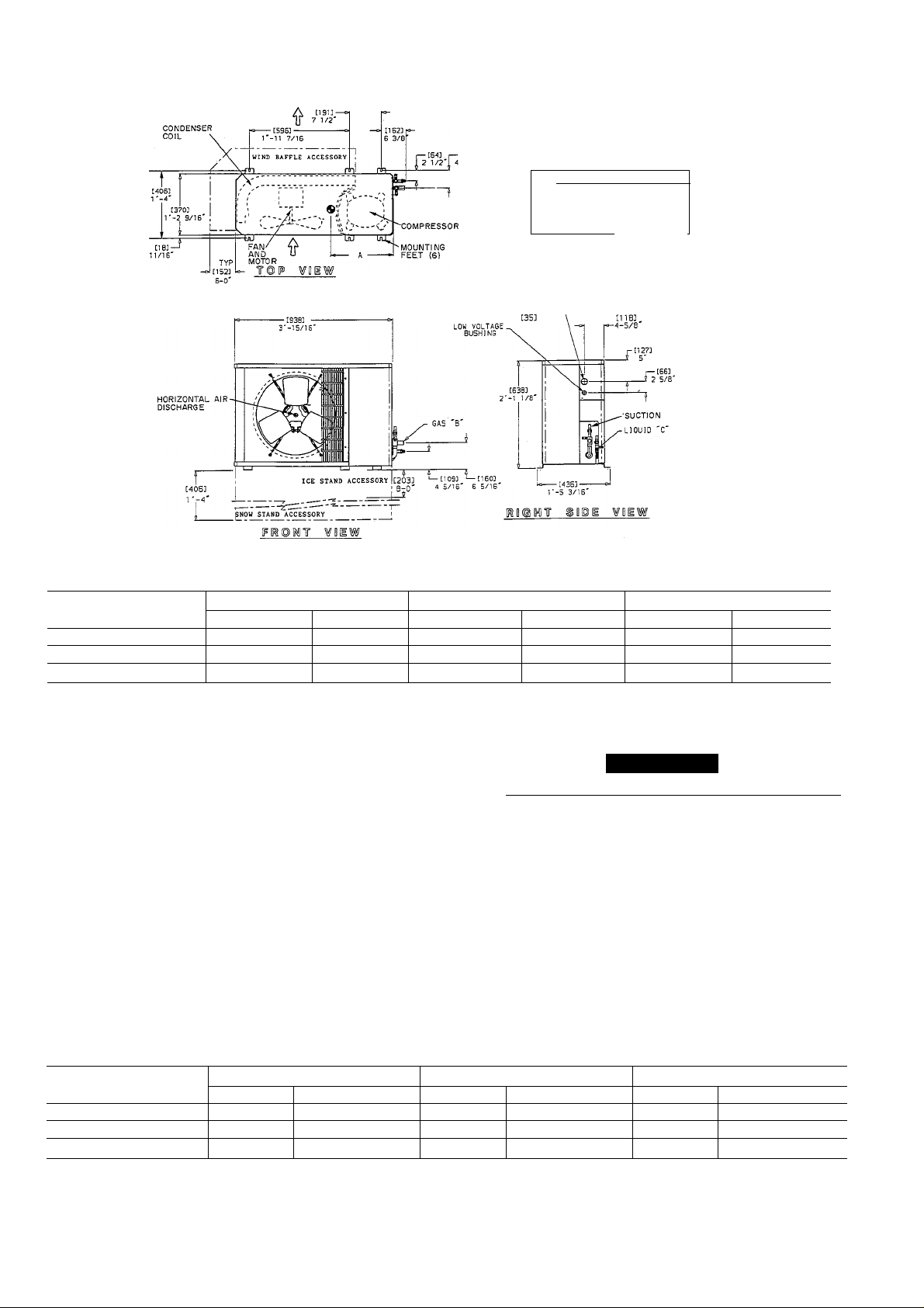
provided in unit base. Refer to unit mounting pattern to determine
base size and knockout hole locations. (See Fig. 2.)
Allow sufficient space for airflow clearance, wiring, refrigerant
piping and servicing of unit. Locate unit so condenser airflow is
unrestricted on both sides. A minimum 6-in. (152mm) clearance
above and 6 ft (1.83m) between units must be maintained. (See
Fig. 2.)
Fig. 1—Model 38QRA
be mounted on a level pad directly on base legs or
g m>mt( ШОП accessory snow stand at support points. See Fig. 2 and
4^^Р^ВДег of gravity. Position unit so water or ice from roof
i^aqjpt drop directly onto unit.
levate Unit
: drainage the heat pump must be raised off the mounting
surface? Use accessory snow rack or ice stand where prolonged
subfreezing temperatures or heavy snow occur. Refer to separate
installation instructions packaged with these accessories.
In rooftop applications, locate unit at least 6 in. (152mm) above
roof surface on a level platform or frame. Place unit above a loadbearing wall and isolate unit and tubing set from structure. Arrange
supporting members to adequately support unit and minimize
transmission of vibration to building. Consult local codes govern
ing rooftop applications.
RIGGING
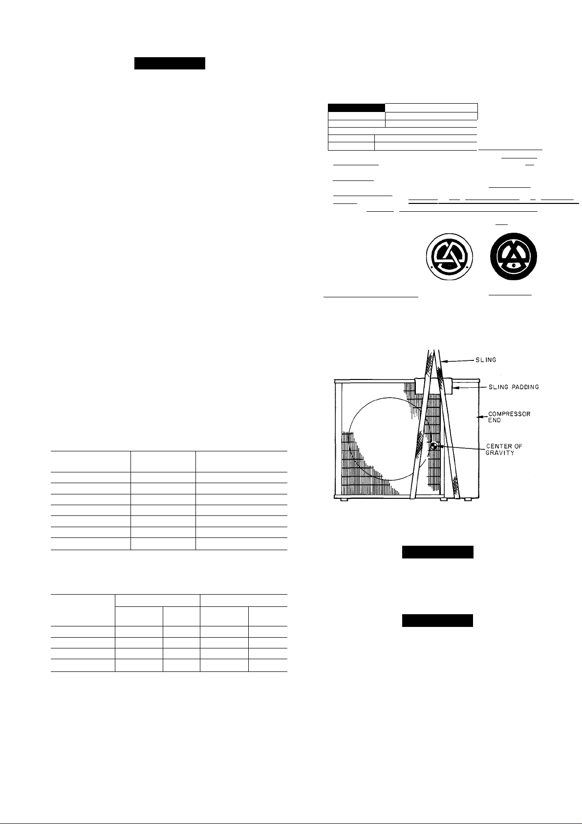
When lifting unit for rooftop mounting, keep unit upright. Lift unit
using a sling. Use cardboard or padding under sling, and spreader
bars to prevent sling damage to unit. (See Fig. 4.) See Figs. 2 and
4 for center of gravity reference. Install unit so that coil does not
face into prevailing winds. If this cannot be done, and constant
A90280
Manufacturer reserves the right to discontinue, or change at any time, specifications or designs without notice and without incurring obiigations.
Book 1 4
Tab 5a 5a
PC 101 Catalog No. 533-858
Printed in U.S.A. Form 38QRA-1SI
Pg 1
10-91
Replaces: New
Page 2
1-6
HIGH VOLTAGE
1-1/8' DIA.
CLEARANCES FOR SERVICE AND AIRFLOW.
ALLOW 6 IN. ABOVE UNIT.
T
SIN.
i
TOP VIEW
,1
\
B'i i COMPr'i
3FT
Jl
V J* ' - - '
~UU LfCr
A90304
UNIT SIZE
018—036 10
036 30
048-060 1 & 30
In.
16 406.4
18-7/16
18-7/16
A
(mm)
468.3
468.3
Fig. 2—Dimensional Drawing—38QRA018—060
winds above 25 mph are expected, use Accessory Wind Baffle,
part number KSAWBOIOIAAA or KSAWB0201AAA. See in
structions provided with accessory kit for installation.
B
In. (mm)
36-15/16 938.2
In-. (mm)
23-7/16 595.3
C
44-9/16 1131.9 30-1/2 774.7
44-9/16 1131.9 30-1/2 774.7
A CAUTION
I Be sure unit panels are securely in place prior to rigging. [
Step A—Replace Indoor AccuRater® Piston, if required
Check indoor coil piston to see if it matches the required piston
shown on unit rating plate. If it does not match, replace indoor coil
piston with piston shipped with this unit. (See Fig. 5.) The piston
shipped with outdoor unit is correct for any approved indoor coil
combination. Note that Type A pistons are used on indoor units
and Type B pistons are used on 38QRA outdoor units. Do not
interchange piston types. (See Fig. 5.) For optimum cyclic perfor
mance, installation of liquid solenoid valve is recommended.
Consult local distributor for liquid solenoid valve kit and hard start
kit part number, if required.
UNIT SIZE
018—036 1 0 23x42
036 3 0 24 X 50
048—060 1 and 3 0
SUPPORT FEET
In.
24 X 50
Table 1—Minimum Mounting Pad Dimensions
SNOW STAND
(mm)
584.2 X 1066.8
609.6x 1270.0 28 X 50 711.2 X 1270.0
609.6 X 1270.0
In. (mm)
26 X 42
660.4 X 1066.8 26 X 42
28 X 50 711.2 X 1270.0
ICE STAND
In.
(mm)
660.4 X 1066.8
26x50 660.4 X 1270.0
26x50
660.4 X 1270.0
Page 3
A CAUTION
DO NOT BURY MORE THAN 36 IN. (914mm) OF RE
FRIGERANT TUBING IN GROUND. If any section of
tubing is buried, there must be a 6-in.(152mm) vertical rise to
the valve connections on the outdoor unit. If more than the
recommended length is buried, refrigerant may migrate to
cooler buried section during extended periods of unit shut
down, causing refrigerant slugging and possible compressor
damage at start-up.
Step 5—Make Piping Connections
Outdoor units may be connected to indoor sections using accessory
tubing package or field-supplied tubing of refrigerant grade,
correct size, and condition. The liquid- and vapor-tube diameters
can be determined by using Table 3. For tubing requirements
beyond 50 ft (15.24m), obtain information from your local
distributor.
If either refrigerant tubing or indoor coil is exposed to atmospheric
conditions for longer than 5 minutes, it must be evacuated to 1000
microns to eliminate contamination and moisture in the system.
Run refrigerant tubes as directly as possible, avoiding unnecessary
turns and bends. Suspend refrigerant tubes so they do not damage
insulation on vapor tube and do not transmit vibration to the
structure. Also, when passing refrigerant tubes through the wall,
seal opening so vibration is not transmitted to stmcture. Leave
some slack in refrigerant tubes between structure and unit to
absorb vibration.
OUTDOOR UNIT CONNECTED TO FACTORY APPROVED
INDOOR UNIT — Outdoor unit contains holding refrigerant
charge only. See Table 2 for correct system charge when con
nected by 25 ft (7.62m) of field-supplied or factory accessory
tubing. Add charge as required to achieve correct total. For long
line application information, contact your local distributor.
CARRIER CORP.
MODEL N0.
SERIAL N0.
1 DF.SIGN/TEST PRESSURE GAGE 1
HIGH PSI 300 kPa 2068
TSEZ'PSl
COMPRESSOR
FAN MOTOR
powgPi Supply
VOLTAGE RAN5F
MIN ¿I
SYSTEM
IN 46206
150 TPo 1034
VOLTS AC
EHÜI £LA
VOLTS
MAX MIN
IMAX■ FU5E/HASR TyRE'';CB; AHPT
PER Installation InSFRuCHW
V MADE IN MEXICO
Fig. 3—Unit Rating Piate
SUITABLE FOR
OUTDOOR USE
REFRIGERANT:
R-22
HOLDING CHARGE
PI5T0N
nn
Phi Ih7I
CERTIFICATION APPLIES QH.Y
IKN THE CO(f>LETE SYSTD1
IS LISTED WITH ARI
I 317204-401 REV.
LBS kg
OP
A90282
Table 2—Refrigerant Charge
OUTDOOR
UNIT
018
024 1
030
036
036
048
060
PHASE
1
1
1
3
1 &3 9.44
1 &3
CHARGE (LB)
4.25
4.75
6.00
7.00
11.63
11.75
Table 3—Refrigerant Connections and Recom
mended Liquid and Vapor Tube Diameters (In.)
UNIT
SIZE
018,024,030 3/8
036 3/8 3/8
048 3/8 3/8 7/8
060 3/8 3/8 7/8
Tube diameters are for lengths up to 50 ft. For tubing lengths greater than 50
ft, consult Long-Line Application Guideline.
LIQUID
Connect
Dia
Tube
Dia
3/8
REFRIGERANT TUBING — Connect tubing to fittings on out
door unit vapor and liquid service valves. (See Fig. 2.) Remove
brass piston retainer. Insert outdoor piston shipped in bag with
indoor piston in the liquid service valve, replace brass piston
retainer and connect sweat adapter provided. (See Fig. 5.)
VAPOR
Connect
Dia
5/8
3/4
Tube
Dia
5/8
3/4
7/8
1-1/8
Fig. 4—Rigging
A90285
A CAUTION
A brazing shield MUST be used when tubing sets ate being
brazed to the service valves to prevent damage to the painted
unit surface.
A CAUTION
To avoid valve damage while brazing, service valves must be
wrapped with a heat-sinking material such as a wet cloth.
FILTER DRIER — Install in field liquid line, if used.
SWEAT CONNECTION — Use refrigerant grade tubing. Service
valves are closed from factory and ready for brazing. After
wrapping the service valve with a wet cloth, the tubing set can be
brazed to the service valve using either silver bearing or non-silver
bearing brazing material. Consult local code requirements. Refrig
erant tubing and indoor coil are now ready for leak testing. This
check should include all field and factory joints.
Page 4

NOTE: Unit is shipped with R-22 factory holding charge indi
cated on unit rating plate.
TYPE A
A90287
TYPE B
A90300
Fig. 5—AccuRater® (Bypass Type Component)
Step 6—Make Electrical Connections
Be sure field wiring complies with local and national fire, safety
and electrical codes, and voltage to system is within limits shown
on unit rating plate. Contact local power company for correction of
improper voltage. See unit rating plate for recommended circuit
protection device and minimum circuit amps for wire size.
NOTE: Operation of unit on improper line voltage constitutes
abuse and could affect unit reliability. See unit rating plate. Do not
install unit in system where voltage may fluctuate above or below
permissible limits.
NOTE: Use copper wire only between disconnect switch and
unit.
BRANCH CIRCUIT DISCONNECT - Install branch circuit dis
connect per NEC of adequate size to handle unit starting current.
Locate disconnect within sight from and readily accessible from
unit, per Section 440-14 of NEC.
A WARNING
According to NEC, ANSI/NFPA 70, and local codes, the
cabinet must have an uninterrupted or unbroken ground, to
minimize personal injury if an electrical fault should occur.
The ground may consist of electrical wire or metal conduit
when installed in accordance with existing electrical codes.
Failure to follow this warning could result in an electric
shock, fire, or death.
GROUND AND POWER WIRES — Route power wires through
opening in unit side panel and connect in unit control box as shown
on unit wiring label and Fig. 6. Unit must be grounded.
Factory Wiring
Fig. 6—Line Power Connections
A91315
CONTROL CIRCUIT WIRING - Control voltage is 24 volts (40
va minimum). See Fig.. 7 and unit wiring label for field-supplied
wiring details. Route control wires through opening in unit side
panel to connection in unit control box. Use furnace or fan coil
transformer as 24 volt (40 va minimum) supply for system or use
accessory transformer.
NOTE: Use No. 18 AWG color-coded, insulated (35 C mini
mum) wires. If thermostat is located more than 100 ft from unit (as
measured along the control voltage wires), use No. 16 AWG
color-coded wires to avoid excessive voltage drop.
NOTE: The defrost timer is factory set for 90-minute cycles. The
timer can be field set for 30- and 50-minute cycles depending on
defrost conditions in your geographical location.
Step 7—Install Electrical Accessories
Refer to the individual instructions packaged with kits or acces
sories when installing.
See your local distributor or dealer for specific component
information.
Step 8—Start-Up
1. When equipped with a crankcase heater, energize crankcase
heater a minimum of 24 hours before starting unit. To energize
heater only, set thermostat at OFF position and close electrical
disconnect to outdoor unit.
2. Fully back seat (open) liquid- and vapor-tube service valves.
3. Unit is shipped with valve stem(s) front seated and caps
installed. Replace stem caps after system is opened to refrig
erant flow (back seated). Replace caps finger tight plus
1/6-tum.
4. Close electrical disconnects to energize system.
5. Set room thermostat at desired temperature.
6. Set room thermostat at HEAT or COOL and fan switch at ON
or AUTO, as desired. Operate unit for 15 minutes.
SEQUENCE OF OPERATION — With power supplied to indoor
and outdoor units, transformer and crankcase heater are energized.
Page 5

SYSTEMS WITHOUT OUTDOOR THERMOSTATS
Thermostat Indoor Outdoor
Subbase ^ . ,
SYSTEMS WITH ONE OUTDOOR THERMOSTAT
Thermostat Indoor
Subbase
Splice Terminal
Connection Board
D VWTH FF1A, 40nc FAN COIL
Terminal
Board
! V FIELO SPLICE
Thermostat
Subbase
SYSTEMS WITH TWO OUTDOOR THERMOSTATS
Terminal
Board
USED WITH FD3A, FB4A. FB5A. FK4A,
40AQ, 40DQ, 40QBAÎH OR 40YAWYZ
Terminal
Board
A88285
When the thermostat is satisfied, its contacts open, de-energizing
the contactor and sequencer. All heaters and motors should stop.
Defrost
The defrost control is a time/temperature control which includes a
field-selectable time period between defrost cycles (30, 50 and 90
minutes, factory set at 90 minutes). Quick connects are located at
board edge.
The electronic timer and the defrost cycle will start only when the
contactor is energized, defrost thermostat is closed and the timing
device has completed one cycle.
The defrost mode is identical to the cooling mode except that the
outdoor fan motor stops and second stage heat is turned on to
continue warming the conditioned space.
A WARNING
Service valve gage ports are not equipped with Schrader
valves. To prevent personal injury, make sure gage manifold
is connected to the valve gage ports before moving valves off
fully back seated position. Wear safety glasses and gloves
when handling refrigerant.
ik CAUTION
Compressor damage may occur if system is overcharged. |
USED WITH {?1A. 4QRC FAN COIL
REMOVE FAaORYINSTAUEO JUMPERS ON INDOOR FAN COIL TERMINAL BOARD WHEN INSTALUNSOUTDOORTHERMOSTATS
- FACTOflVVVIRlNG
■ FIEIOWIRING
OU'BOORTHERMOSTAT
SUPPIEUENTAI. HEAT RELAV
A88286
Fig. 7—Typical Circuit Connections
Cooling
On a “call for cooling”, the thermostat “makes” circuits R- O,
R-Y and R-G. Circuit R-0 energizes the reversing valve, switching
it to cooling position. Circuit R-Y energizes the contactor, starting
outdoor fan motor and compressor circuit. R-G energizes the
indoor unit blower relay, starting the indoor blower motor on high
speed.
When the thermostat is satisfied, its contacts open, de-energizing
the contactor and blower relay. Compressor and motors should
stop.
Heating
On a “call for heating”, the thermostat “makes’ ’ circuits R- Y and
R-G. Circuit R-Y energizes contactor, starting outdoor fan motor
and compressor. Circuit R-G energizes the indoor blower relay,
starting the blower motor on high speed.
Should the temperature continue to fall, R-W2 is made through the
second-stage room thermostat bulb. Circuit R-W2 energizes a
sequencer, bringing on the first bank of supplemental electric heat
and providing electrical potential to the second heater sequencer (if
used). If the outdoor temperature falls below the setting of the
outdoor thermostat, (field-installed operation) the contacts close to
complete the circuit and bring on the second bank of supplemental
electric heat.
Step 9—Refrigerant Charging
NOTE: See Table 2 for correct system charge of tested combi
nation.
Cooling
To check and adjust charge during cooling season, use Tables 4
and 5 and the following procedure:
1. Operate unit a minimum of 15 minutes before checking
charge.
2. Measure suction pressure by attaching a gage to suction valve
service port.
Table 4—Superheat Charging Table
(Superheat Entering Suction Service Valve)
OUTDOOR
TEMP
—Do not attempt to charge system under these conditions or refrigerant
slugging may occur.
50
55
9
60 7 10 12 15 18
65
70
75
80 — — — — 5 8
85
90
95
100 8 12 15 20
105 5 9 13
110
115 8
—
_
3. Measure suction line temperature by attaching a service
thermometer to unit suction line near suction valve. Insulate
thermometer for accurate readings.
4. Measure outdoor coil inlet air dry-bulb temperature with a
second thermometer.
5. Measure indoor coil inlet air wet-bulb temperature with a sling
psychrometer.
INDOOR COIL ENTERING AIR (F) WB
52 54 56 58 60
17
12 14
6 10 13
7 10 13 16
— —
6 9
62 64 66
23 26 29
20
24 27
21
16 19 21
19 21
12 15 18 21 24 28 31
12
8
5 9 13 16 20
68 70
32
35 37 40
30
33 35
24 27 30
24 27
21
15 18
11
15 19 22 26 30
6 10 14
6 11
72
38 40 43
33 36 38
33 36 39
30
25 28
24 27 31
22 25 29
18
17 22 26
15
14 18 23
74
42
34 37
31 35
23 27
20 25
76
45
41
33
Page 6

6. Using Table 4, find air temperature entering outdoor coil and
wet-bulb temperature entering indoor coil. At this intersection
note the superheat.
Table 5—Required Suction Tube Temperature (F)
(Entering Suction Service Valve)
A CAUTION
To prevent personal injury, wear safety glasses and gloves
when handling refrigerant. Do not overcharge system. This
can cause compressor flooding.
A CAUTION
Service valves must be fully back seated to close service port.
There is no Schrader valve at the service port and failure to
back seat the valve could result in loss of system charge or
personal injury.
7. Using Table 5, find superheat temperature and suction pres
sure; note suction line temperature.
8. If unit has higher suction line temperature than charted
temperature, add refrigerant until charted temperature is
reached (+/- 3 F).
9. If unit has lower suction line temperature than charted
temperature, bleed refrigerant until charted temperature is
reached (+/- 3 F).
10. If air temperature entering outdoor coil or pressure at suction
valve changes, charge to new suction line temperature indi
cated in chart.
11. This procedure is valid, independent of indoor air quantity.
TEMP(F)
0
2
4
6
8 43
10
12
14 49 51
16
18 53 55
20
22
24
26
28
30
32
34 69 71
36
38
40 75 77
64.2 67.1
61.5
37
35
37
39
39 41
41
43 45
45 47
45 47
47 49
51
53 55
55 57 59
57
59 61 63
59 61
61
63 65 67 69
63 65 67
65 67
67
69
71
73 75 77 79 81 83
73 75 77
70.0
39 41
41
43
43 45
47 49 51
49
49 51
51 53
53 55
57 59 61 63 65
57
59
61
63 65
69
71 73 75 77
69
71
73 75
73 75
79
79 81
73.0 76.0
43 45 47
45 47
47
'51 53 55 57 59
53
55
57
61 63 65 67 69
63 65
65
67
71
77
81 83
83 85 87
79.2 82.4 85.7
49 51 53
49 51
53 55
55 57
57
, 59
59 61
67
67
69 71 73
69 71
71
73 75
73 75
77
79 81
79
81 83
85
49 51
53 55
59
61 63
63
69
73
77 79
79 81
85 .
87 89
89 91
57
61
65
67
71
75
77
83
85
87
Heating
To check system operation during heating cycle, use Table 6. This
table indicates whether a correct relationship exists between
system operating pressure and air temperatures entering indoor and
outdoor units. In heating mode, check should be made approxi
mately 15 minutes after defrost with unit running with a clean coil.
If pressure and temperature do not match on chart, system
refrigerant charge may not be correct or other system abnormali
ties may exist. Do not use table to adjust refrigerant charge.
When recharging is necessary during heating season, weigh in total
charge as indicated in Table 2. Remove or recycle any refrigerant
remaining in system before recharging. If the system has lost
complete charge, evacuate and recharge by weight. Service port
connections are provided on liquid- and suction-line service
valves. For evacuation and recharging, Dial-a-Charge charging
cylinder, or similar device, is an accurate device for recharging
system by weight.
CARE AND MAINTENANCE
For continuing high performance, and to minimize possible
equipment failure, it is essential that periodic maintenance be
performed on this equipment. Consult your servicing contractor or
users manual for the proper frequency of maintenance. Frequency
of maintenance may vary depending upon geographic areas, such
as coastal applications.
Page 7

Unit
38QRA
018
024
030
036 1 Phase
036 3 Phase
(HIGH PRESSURE AT !
Indoor D17
Bulb
Temp (F)
60
70
80
60
70
80
60
70
80
60
70
80
60
70
80
Table 6—Heating Check Chart
HEATING OPERATION PRESSURE TABLE, FIXED RESTRICTOR
Outdoor Temperature (F) Dry Bulb
60
High
Low
Suction 66.8
High
Low
Suction
High 288.0
Low
Suction 73.4
High
Low
Suction
High 254.2
Low
Suction
High 279.9
Low 85.7
Suction 72.7
High 157.7
Low
Suction 48.2
High 186.6
Low
Suction 52.7
High
Low
Suction 56.2
High 226.1
Low
Suction
High 252.0
Low 130.2
Suction
High
Low
Suction
High 193.7 180.4
Low 71.4
Suction 58.1
High 227.8
Low
Suction 65.7
High 235.4
Low 106.7
Suction 72.7
231.0
80.4
257.0
84.5
70.5
87.6
226.9
79.1
67.2
83.1
70.7
64.9 58.9 53.0 46.8 40.1
70.0 62.1 54.2
216.0 205.3
74.5 65.0 55.6 45.8 39.9 34.1 28.0
117.7
65.3 55.4 45.6 35.4 30.2 25.0 19.6
65.8
282.3 241.3 200.3
144.8 121.4 97.9
67.3 56.9 46.4 35.7 31.5 27.3 23.0
79.7
50
208.3 185.6
70.6
57.9
231.6
73.2
60.0
260.0
75.6
62.5
203.2
67.8 56.5 44.9 40.0 35.2 30.2
56.9
222.1 189.9 156.8 155.3 153.8 152.3
65.8
55.1 39.5
251.3
70.9
59.4 46.2
151.3 144.9 138.3
43.1
177.5
45.8 38.9
48.0 39.9 31.5 26.9 22.3 17.6
219.6 213.0 206.3 183.0 159.6 135.6
110.8 103.9 96.8 84.6
230.3 208.5 186.1 177.2 168.3 159.1
118.3
56.5
64.4 57.5
52.3 46.6
200.1
94.6 109.5 124.9
61.1 56.6
222.6
88.3 69.9 50.9 42.9 34.9
62.9 53.0 42.9 35.5 28.1 20.5
40
60.8 53.7 46.6
49.0 42.9 36.8 30.7 24.6
206.1
61.9
49.5 43.2 36.8 30.5
232.0 218.8 205.5 192.3 179.0
63.6
51.6 44.7 37.9
179.4
46.7
48.5
222.6
56.2
37.9
168.4
194.7 183.7 177.4 171.2 164.7
106.4
47.3 37.7 32.2
167.0 153.3 145.8 138.3 130.6
172.4
209.9 196.7
30 20
174.2
194.1 182.1
54.4
55.6
155.0
36.1 31.9 ,
30.6
23.4 22.7
193.1
41.0
32.5
32.6 27.3 22.0
159.0
46.0
31.8
94.2 85.3 76.4 67.3
158.0
73.8 74.8 75.8 76.9
50.3
40.6
143.9 144.9 145.8 146.8
51.9
162.8 151.4
46.8 39.3
47.6
148.2
29.6 28.6 27.5
153.7
36.5 32.1 27.5
28.8 25.1
132.2
153.4
40.4
27.4
167.5
42.1
33.6 26.7 19.5
92.4
41.4 30.8 20.0
187.5
10
140.0
39.5
170.0 158.0
39.6
31.0
141.5 134.5
27.7 23.4
21.9
114.4
126.0
33.4
147.8
34.7 28.9
23.0
72.4
26.6 20.9
177.0
33.9
59.8 26.3
178.4
32.4
31.7
24.1
31.6
24.1
21.2
73.8
21.4
119.7
26.5
16.5
142.1
18.4
59.8
186.8
25.5
168.9
26.7
0
Page 8

Table 6—Heating Check Chart Cont’d
HEATING OPERATION PRESSURE TABLE, FIXED RESTRICTOR
Unit
38QRA
048
060
Indoor Dry
Bulb
Temp (F)
60
70
80
60
70
80
High
Low
Suction
High
Low
Suction
High
Low
Suction
High
Low
Suction
High
Low
Suction
High
Low
Suction
Outdoor Temperature (F) Dry Bulb
60
273.5
82.9
68.3
295.2 256.7
85.2 71.1
69.5 56.9
314.5
87.2
70.6
228.9 210.7
85.9
63.3
258.3
86.9
65.1
290.0
88.4
66.5 57.3 48.2
50
239.3 205.2 170.0 170.0 170.1 170.1
71.3 59.7 47.7 42.2 36.6
57.6 47.0 36.0
218.2 178.5
57.1
44.3 31.3
274.0
70.9
56.1 41.7
74.1
54.6
238.7
74.9 62.9
56.1 47.0
268.7
76.0
233.5 191.8
54.6 37.8
192.5 173.8
62.2 50.0
45.8
219.2 199.0 184.9 170.9
247.4 225.5 209.6
63.7 50.9 42.2 33.5 24.5
40
30 20 10 0
30.9
31.8 2.6 23.2
178.7 179.0 179.2
42.6
26.8
36.8
50.5 41.8 33.0 24.0
37.7
38.7
38.7
28.5
194.3 196.9
35.6
25.5
161.5 149.2 136.6
41.3 32.5 23.5
30.2 23.6
31.0
31.9
34.9 30.9
25.8
33.4
24.2
24.4
193.6 177.2
25.2 18.2
22.9
199.5
31.1
22.9
16.8
156.4
17.5
Copyright 1991 Carrier Corporation Indpis, IN 46206 13015
Manufacturer reserves the right to discontinue, or change at any time, specifications or designs without notice and without incurring obiigations.
BookI 1 I 4 PC 101 Catalog No. 533-858 Printed in U.S.A. Form 38QRA-1SI Pg 8 10-91 Repiaces: New
Tab I5a|5a
 Loading...