

Page 1
38QN
HEATING & COOLING
Heat Pumps—Outdoor Section
Installation and Start-Up Instructions
SAFETY CONSIDERATIONS
Installing and servicing air conditioning equipment can be
hazardous due to system pressure and electrical compo
nents. Only trained and qualified service personnel should
install or service air conditioning equipment.
Untrained personnel can perform basic maintenance, such
as cleaning and replacing filters. All other operations should
be performed by trained service personnel. When working
on air conditioning equipment, observe precautions in litera
ture and on tags emd labels attached to unit.
Follow all safety codes. Wear safety glasses and work
gloves. Use quenching cloth for brazing operations. Have
fire extinguisher available. Read these instructions thor
oughly. Consult local building codes and National Electrical
Code (NEC) for special installation requirements.
A WARNING
Before installing or servicing unit, always turn off main
power to system. There may be more than one discon
nect switch. Turn off accessory heater power if applica
ble. Electrical shock can cause personal injury.
INSTALLATION
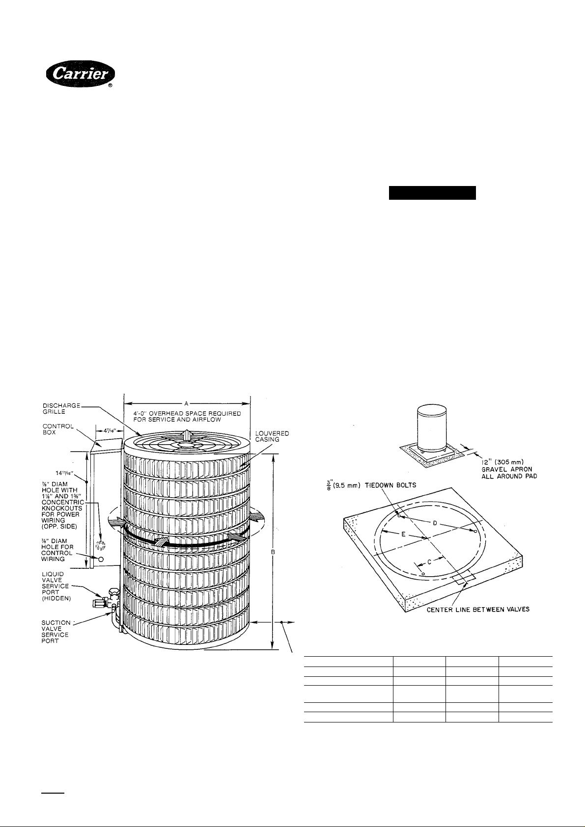
Step 1—Check Equipment and Jobsite—Install on a sohd,
level mounting pad. It is recommended that unit be
attached to pad using tiedown bolts. Fasten unit to pad
using holes provided in unit mounting feet. See Fig. 1.
A87150
Dimensions (ft-in.)
AIRFLOW
A86167
r-6" AIRFLOW AND
SERVICE CLEARANCE
AROUND UNIT — 12"
ON VALVE SIDE
Model 38QN 015-030 036-048 060
Diameters
Squares (minimum)
Tiedown Bolt
Locations C
1-9’2
1-11
0-6=4
D
1-4
E 0-9V
Fig. 1—Dimensions, Connections and Mounting Pad (Refer to Tabie 1)
Manufacturer reserves the right to discontinue, or change at any time, specifications or designs without notice and without incurring obiigations.
Book| 1 I 4
Tab l5al5a
PC 101 Cataiog No. 533-820 Printed in U.S.A. Form 38QN-10Si 10-87 Pg 1 Repiaces: 38QN-9Si
2-5\ 3-3
2-6 3-4
0-9’'2
1-10^2
1-1
1-T=16
2-7
1-5^8
Page 2
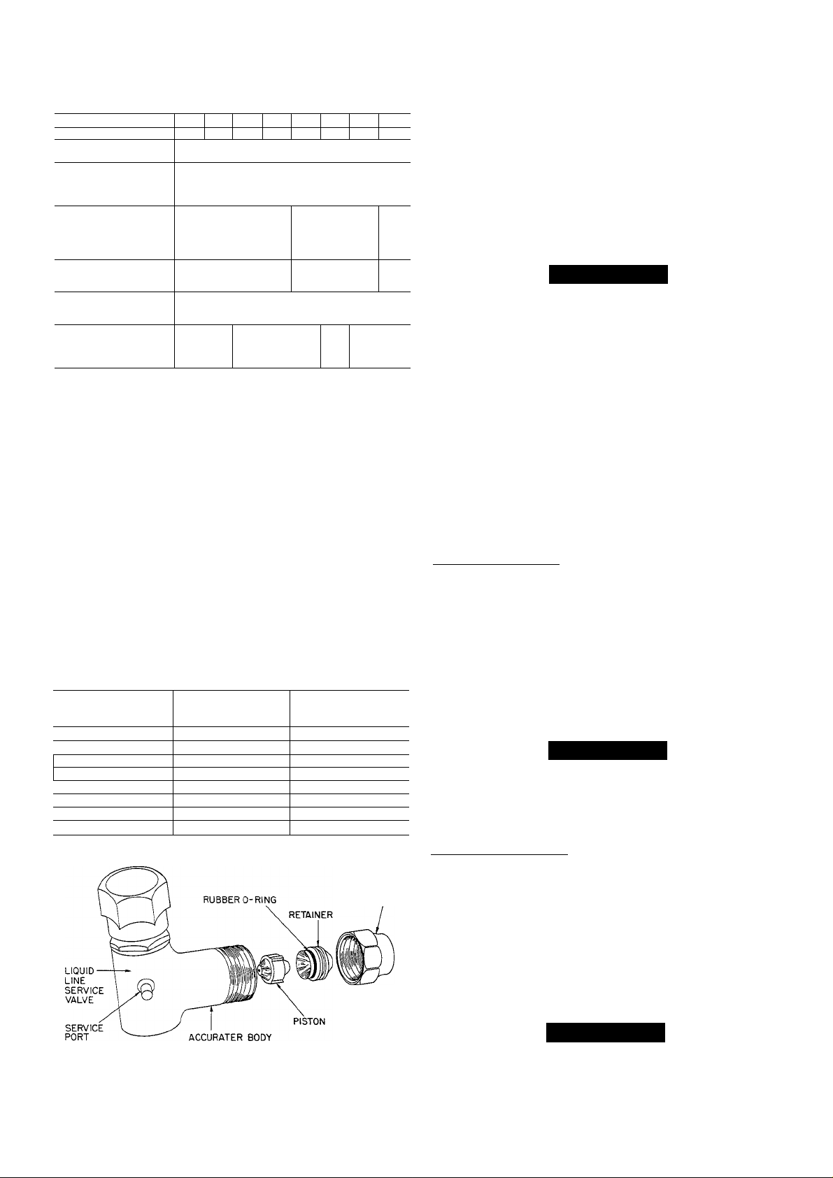
Table 1—Physical Data
MODEL 38QN
OPER WT (lb)* 132
REFRIGERANT
Control
CONDFAN
Air Discharge
AirQty(Cfm)
Mtr Rpm (60 Hz)
CONDCOIL(fins/in.)
Tube Diam
Rows
Refrig Ckts
Face Area (sq ft)
DIMENSIONS (ft-in.)
Diameter A
Height B
CONNECT, (in. ODF)
Suction
Liquid
REFRIG LINES
(in. ODF)
Suction
Liquid
♦Weight increases slightly with addition of any accessories.
t38QN048-060 require lYs-in. suction line for optimum perform
ance. A %- X 17s-in. connection adapter accessory (Carrier Part
No. 28AU900061) is available. If a 7s-in. accessory tubing pack
age is used, expect a slight capacity loss.
015 018
1850 1 2400 1 3100 1 3800 | 4000 | 5000
Compatible Fitting (Suction) & Flare (Liquid)
When installing, allow sufiBcient space for edrflow clearance,
wiring, refrigerant piping and servicing. Maintain a mini
mum of 4 ft clearance from obstructions above and 18 in.
around unit (12 in. on valve side). Maintedn a distance of 24
in. between heat pumps. Position so water or ice from roof
or eaves cannot fall directly on unit.
Step 2—Replace Indoor AccuRater™ Piston, if Required-
Check indoor cod piston to see if it matches the required pis
ton listed in Table 2. If it does not match, replace indoor cod
piston with piston shipped with this outdoor unit (located in
plastic bag taped to valves). See Fig. 2.
024
151 155 180 195
830 1 1075 850 | 1075 | 840
2 2
12.77
1-9%
% 1 %
%
030 036 042
1
Vertical
Vin.
22
1
%
%
6
E-Coil
AccuRater'^'^ (Bypass Type)
Propeller Type, Direct Drive
189 235 270
2 1 3 1
17.33
2-574
2-7
% 1%t
048 060
)
21.88
3-2%
Table 2—AccuRater™ Chart
OUTDOOR
UNIT
38QN
015 35 46
018 40
024
030 55 65
036
042 67 73
048 73 82
060
OUTDOOR
PISTON
46 59
61
78
INDOOR
PISTON
49
73
101
FLARE NUT
Step 3—Make Piping Connections—Outdoor units may be
connected to indoor sections using Carrier accessory tubing
package or field-supplied tubing of refrigerant grade, cor
rect size and condition (Table 1). For tubing requirements
beyond 50 ft, obtain information from local Carrier
distributor.
Outdoor Units Connected to Carrier-Approved Indoor
Units—Outdoor units contain correct system refrigerant
charge for operation with indoor unit of the same size when
connected by 25 ft of field-supplied or Carrier accessory tub
ing. Check refrigerant charge for maximum efficiency.
A CAUTION
DO NOT BURY MORE THAN 3 FT OF REFRIGER
ANT TUBING IN GROUND. If any section of tubing
is buried, there must be a 6-in. vertical rise to valve con
nections on outdoor unit. If more than the recom
mended length is buried, refrigerant may migrate to
cooler buried section during extended periods of unit
shutdown. This causes refrigerant slugging and possi
ble compressor damage at start-up.
CONNECT REFRIGERANT LINES to fittings on unit
suction and liquid service valves (Fig. 1). Liquid service
valve has flare fitting; suction service valve has Compatible
Fitting. Make suction line connection first. Slide flare nut
on liquid line, then flare and connect liquid line. Use a maxi
mum torque of 15 ft-lb to tighten flare nut. (Do not disas
semble AccuRater.) Unit Compatible Fitting permits
mechanical or sweat connection as described below.
Models 38QN048,060—When using iVs in. field-supplied
refrigerant suction line, sweat-connect suction line to lYs in.
end of required connection adapter. Be sure to provide a
heat sink at the service valve to prevent damage during
sweating operation. Connect %-in. end of adapter to unit suc
tion line Compatible Fitting. Connect liquid refrigerant line
to unit. When a 7s-in. field-supplied suction hne is used, pro
vide a field-supplied %-in. to 7s-in. suction line adapter (not
necessary if 38LS accessory tube is used).
NOTE: Compatible Fitting on outdoor section has alumi
num plug located beneath compatible nut on suction valve.
Plug keeps contaminants out of Compatible Fitting.
A CAUTION
When removing compatible nut, be careful pressure
build-up does not cause aluminum plug to blow and
cause personal injury. After tubing is hooked up, dis
card plug.
Mechanical Connection—Mate one set of connections at a
time.
1. Remove nut on Compatible Fitting.
2. Remove plug and be sure 0-ring is in the groove inside
the Compatible Fitting.
3. Cut tubing to correct length. Deburr and size as neces
sary. Slide nut onto tube.
4. Insert tube into Compatible Fitting until it bottoms.
Tighten nut until it bottoms on shoulder of fitting or
valve. Keep tube bottomed in Compatible Fitting while
tightening nut.
A87151
Fig. 2—AccuRater (Bypass Type) Components
A CAUTION
If undersized, damaged or eUipticaUy-shaped tubing is
used when making Compatible Fitting, leaks may
result.
Page 3
Sweat Connection—Use refrigerant grade tubing.
1. Remove locking nut, plug, rubber 0-ring and Schrader
core and cap from valve service port.
2. Cut tubing to correct length. Deburr and size as
necessary.
3. Insert tube in Compatible Fitting until it bottoms.
NOTE: Wrap top and bottom of service valves in wet
cloth to prevent damage by heat. Solder with lowtemperature (430 F) silver edloy solder.
4. Replace Schrader core and cap.
5. Evacuate or purge system with field-supplied
refrigerant.
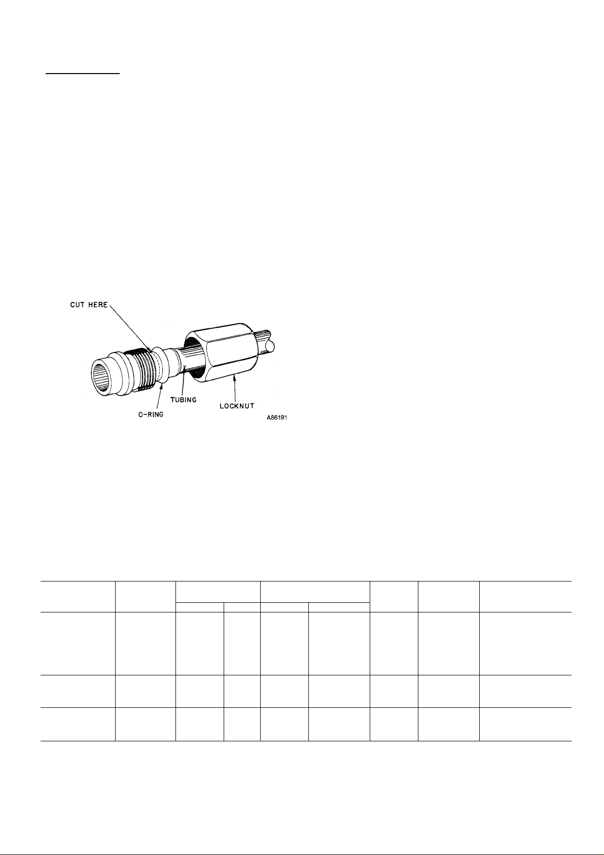
Compatible Fitting Repair
MECHANICAL CONNECTION-Frontseat unit service
valves. Relieve refrigerant pressure from tubing. Back off
locknut from Compatible Fitting onto tube. Cut fitting
between threads and 0-ring. See Fig. 3. Remove tubing sec
tion remaining in threaded portion of fitting. Discard
locknut.
COMPATIBLE FITTING
Clean, flux and insert new tube end into remaining portion
of Compatible Fitting. Wrap valve in wet rag to prevent
damaging factory-made joints. Heat and apply low-tempera
ture (430 F) solder.
SWEAT CONNECTION-Frontseat unit service valves.
Relieve refrigerant pressure from tubing. Clean and flux
around leak. Repair, using low-temperature (430 F) solder.
Evacuate or purge evaporator coil and tubing system. Add
refrigerant charge. See Refrigerant Charging.
Step 4—Make Electrical Connections—Be sure field wir
ing comphes with local and national fire, safety and electri
cal codes, and voltage to system is within limits shown in
Table 3. Contact local power company for correction of
improper fine voltage.
NOTE: Operation of unit on improper line voltage consti
tutes abuse and could affect Carrier warranty. See Table 3.
Do not install unit in system where voltage may fluctuate
above or below permissible limits.
See Table 3 for recommended fuse sizes. When making elec
trical connections, provide clearance at unit for refrigerant
piping connections.
INSTALL BRANCH CIRCUIT DISCONNECT PER NEC
of adequate size to handle unit starting current. Locate dis
connect within sight from and readily accessible from unit,
per Section 440-14 of National Electrical Code (NEC).
ROUTE LINE POWER LEADS-Extend leads from dis
connect through power wiring hole provided (see Fig. 1) and
into unit splice area. Remove control box cover to gain
access to unit wiring.
Fig. 3—-Repair of Mechanicai Connection
Tabie 3—Eiectricai Data (60 Hz)
Three-phase availabie with 036-060 sizes
OUTDOOR
UNIT 38QN
015-32
018-33 49.0
024-32 53.0
030-34 208-230/1 253 197 70.0
036-31
042-31 108.0
048-31 110.0
060-31
036-51 65.0 11.5 0.9 15.3
042-51
048-51 92.0 14.7 1.9 20.2
060-51 130.0 21.4 2.1
036-61
042-61 460/3 506 414
048-61 46.0 7.0 1.6 10.4
060-61 65.0 9.6 1.6 13.9
FLA —Full Load Amps
HACR—Heating, Air Conditioning, Refrigeration
LRA —Locked Rotor Amps
MCA —Minimum Circuit Amps
RLA —Rated Load Amps
NOTE: Control circuit is 24 v on all units and requires external power source.
V/PH OPER VOLTS* COMPR
208/230/3
Max
254 187 80.0 13.3 2.5 19.1
Min
LRA
35.0
86.7
142.0 33.0
32.8
35.0
FAN
RLA
7.2
10.5
13.2
17.6 1.9
18.9
21.8
27.3
5.1 1.6 8.0
7.2 1.6 10.6
♦Permissible limits of the voltage range at which unit will operate
satisfactorily.
tTime-delay fuse.
FLA
0.7
0.7 13.8
2.1 18.6
0.9 24.5
2.6 29.9
1.9 36.0
2.1 43.4
MCA
9.7
24.1
28.9
MAX FUSEt OR
HACR TYPE
CKTBKRAMPS
15
20
30
40
40
50
60
60
25
30
30
, 45
15
15
15
20
Page 4

CONNECT GROUND LEAD AND POWER WIRINGConnect ground lead to ground connection in control box for
safety. Then connect power wiring. See Fig. 4. Splice line
power leads to yellow and black pigtails. Use wire nuts and
tape at each connection. Connect unit wiring to copper
power wiring only.
CONNECT CONTROL POWER WIRING-Route 24-v
control wires through control wiring hole and channel and
connect leads to control wiring terminal board. See Fig. 1
and 6.
Use furnace or fan coil transformer as 24-v (40-va minimum)
supply for system as shown in Fig. 6, or use accessory
transformer.
MOUNT OUTDOOR THERMOSTAT in control box.
Attach brackets with short sheet metal screws to avoid con
tact with coH. Leave capUlary tube coiled in control com
partment making sure it is clear of aU electrical connections
and sharp metal edges.
MOUNT SUPPLEMENTAL HEAT RELAY in convenient
location on indoor unit. Attach with sheet metal screw.
To Start Unit
1. Energize crankcase heater a minimum of 24 hours
before starting unit. To energize heater only, set ther
mostat at OFF position and close electrical disconnect
to outdoor unit.
2. Backseat (open) liquid and suction line service valves.
l-PHASE
CONN. TO
DISCONNECT
PER NEC
'---GROUND LEAD-
----.---------
----------------
---------------
3-PHASE
CONN. TO
DISCONNECT
PER NEC
--------------Field Wiring
--------------
SPLICE CONNECTIONS
FIELD WIRING
FACTORY WIRING
--GROUND LEAD -
Factory Wiring
-[Hgroundin'g lug
— YEL
-------------------
I- PHASE
COND UNIT
-UlGROUNDING LUG
3-PHASE UNIT
Fig. 4—Line Power Connections
Step 5—Start-Up—Heat Anticipator Settings for Room
Thermostat. To set the heat anticipator, move the heat
anticipator to the maximum setting. Determine which ter
minal powers the electric heater controls. With the heaters
energized, measure the amperage between the appropriate
W terminal and R and set the anticipator to the same valve.
Fig. 5 illustrates an easy method of obtaining the actual
amp draw.
Accessory Outdoor Thermostat provides adjustable out
door control of accessory electric heater. This thermostat
makes contact when a drop in outdoor temperature occurs.
It energizes a stage of electric heat when the outdoor tem
perature setting is reached, provided the room thermostat
is on the second stage of heating. One outdoor thermostat is
recommended for each stage of electric heat after the first
stage. Set the outdoor thermostat(s) progressively lower for
each stage. Refer to heat load of building and unit capacity
to determine the correct outdoor thermostat settings.
The accessory supplemental heat relay is required when 2
outdoor thermostats are used. It is automatically energized
by the manually operated supplemental heat switch in the
indoor thermostat subbase. The thermostat locks out com
pressor and the relay bypasses the outdoor thermostats for
electric heater operation during heat pump shutdown. When
one outdoor thermostat is used, a supplemental heat relay is
not required. The supplemental heat switch in the indoor
thermostat subbase bypasses outdoor thermostat, locks out
compressor and activates electric heater.
Unit is shipped with valve stem(s) frontseated, and
caps installed. Replace stem caps after system is
opened to refrigerant flow (backseated). Replace caps
finger tight and tighten additional % turn with wrench.
See sticker on valve cap.
Turn on main disconnect switch(es) to indoor and out
4.
door units.
Set fan switch as desired (ON or AUTO).
5.
Set thermostat dial at desired temperature.
6.
Set selector switch at HEAT or COOL. Operate unit
7.
for 15 minutes.
Check system refrigerant charge. See Refrigerant
8.
Charging.
Motors and controls are designed to operate satisfactorily
in the voltage range shown in Table 3. If necessary to use
manifold gages for servicing, refer to Carrier Standard Serv
ice Techniques Manual, Chapter 1, Refrigerants, Pages 1-5,
Fig. 8 for bypass method of returning charge to system.
Removal of liquid line charging hose without following
these precautions could result in some loss of charge.
Refrigerant Charging (Fig. 7 through 14)
A CAUTION
To prevent personal injury, wear safety glasses and
gloves when handling refrigerant. Do not overcharge
system. This can cause compressor failure.
THERMOSTAT I—^ A
TERMINALS"
---
® 0 ® ©
10 TURNS AROUND JAWS
0.5 AMPS FOR THERMOSTAT SETTING
Fig- 5—Determining Amp Draw
HOOK'AROUNO
VOLT/AMMETER
Page 5

THERMOSTAT
SUBBASE
HH93AZIT3
OR HH93AZI75
(38QN/40AQ 0R40QB WITHOUT ELECTRIC HEATER)
40AQ OR 40QB FAN COIL
COOLING CONTROL KIT
TERMINAL BOARD
38QN
TERMINAL
BOARD
THERMOSTAT
SUBBASE
HH93AZI73 OR
HH93AZI75
COOLING AND TWO-STAGE HEATING
SUPPLEMENTAL HEAT, TWO OUTDOOR THERMOSTATS)
EQUIPPED WITH ELECTRIC HEATER;
40AQ OR 40QB
ELECTRIC HEATER
TERMINAL BOARD
(38QN WITH 40FS/28HQ.VQ
38QN
TERMINAL
BOARD
A87154
THERMOSTAT
SUBBASE
HH93AZI73
ORHH93AZI75
THERMOSTAT
SUBBASE
HH93AZI73
OR HH93AZI75
40AQ OR 40QB
ELECTRIC HEATER
TERMINAL BOARD
COOLING AND TWO-STAGE HEATING
(38QN WITH 40AQ,40QB OR 40FS/28HQ,VQ
SUPPLEMENTAL HEAT, NO OUTDOOR THERMOSTATS)
EQUIPPED WITH ELECTRIC HEATER;
B
40AQ OR 40QB
ELECTRIC HEATER
TERMINAL BOARD
380N
TERMINAL
BOARD
38QN
TERMINAL
BOARD
A87152
TH ERMOSTAT H H07AT17I 40DQ ELEC. HEATER
WITHHH93AZI73(AUT0. (ALL MODELS) 38QN
CHANGEOVER) OR HH93AZI75 LOW VOLTAGE TERM. TERMINAL
(MAN. CHANGEOVER) SUBBASE. SPLICE CONNECTIONS BOARD
SUPPLEMENTAL HEAT, NO OUTDOOR THERMOSTATS)
A87156
(38QN WITH 40AQ,40QB OR 40FS/28HQ.VQ
EQUIPPED WITH ELECTRIC HEATER;
SUPPLEMENTAL HEAT, ONE OUTDOOR THERMOSTAT)
Fig. 6—Control Circuit Connections
A87155
ODT — Outdoor Thermostat
SHR — Supplemental Heat Relay
------------
------------
Factory Wiring
Field Wiring
'Transformer (60 va) located in cooling control kit or electric
heater.
fRemove factory-installed jumper (Connection B) when
installing outdoor thermostats (ODT).
5
Page 6

HEATING CYCLE CHECK CHARTS
PSIG
(kPa)
10
(69)
20
(138)
SUCTION PRESSURE AT SERVICE PORT
30
(207)40(276)
50
(345)
Fig. 7—38QN015 Heating Cycie Check Chart
60
(414)
SUCTION PRESSURE AT SERVICE PORT
Fig. 8—38QN018 Heating Cycie Check Chart
PSIG
(kPa)
(69)
lO
20
(138)
SUCTION PRESSURE AT SERVICE PORT
30
(207)
40
(276)50(345)
Fig. 9—38QN024 Heating Cycle Check Chart
60
(4I4)
A87158
PSIG
(kPa)
lO
(69)
20
(138)
SUCTION PRESSURE AT SERVICE PORT
30
(207)40(276)50(345)
A87159
Fig. 10—38QN030 Heating Cycie Check Chart
60
(4I4)
Page 7

HEATING CYCLE CHECK CHARTS (cont)
PRESS. AT SUCT. SERVICE PORT psig
Fig. 11—38QN036 Heating Cycie Check Chart
SUCTION PRESSURE AT SERVICE PORT
A87160
Fig. 12—38QN042 Heating Cycie Check Chart
Fig. 13—38QN048 Heating Cycle Check Chart
SUCTION PRESSURE AT SERVICE PORT
a87161
Fig. 14--38QN060 Heating Cycie Check Chart
Page 8

To check system operation during heating cycle, use correct
Heating Cycle Check Chart (Fig. 7 through 14). These
charts indicate whether a correct relationship exists
between system operating pressure and air temperatures
entering indoor and outdoor units. If pressure and tempera
ture lines do not intersect on chart, system refrigerant
charge may not be correct or other system abnormalities
may exist. Do not use Heating Cycle Check Charts to adjust
refrigerant charge.
When recharging is necessary during heating season, weigh
in total charge as indicated on unit rating plate. Remove
any refrigerant remedning in system before recharging. If
the system has lost complete charge, evacuate and recharge
by weight. Service port connections are provided on liquid
and suction line service valves. For evacuation and recharg
ing, Dial-A-Charge charging cylinder is an accurate device
for recharging systems by weight.
To check and adjust charge during cooling season, use
Tables 4 and 5 and the following procedure:
1. Operate unit a minimum of 15 minutes before checking
charge.
2. Measure suction pressure by attaching a gage to suc
tion valve service port.
3. Measure suction line temperature by attaching a serv
ice thermometer to unit suction line near suction valve.
Insulate thermometer for accurate readings.
4. Measure outdoor coil inlet air dry-bulb temperature
Table 4—Superheat Charging Table
(Superheat Entering Suction Service Valve)
OUTDOOR
TEMP(F)
55
60
65
70
75
80
85
90
95
100
105
110
115
-Do not attempt
refrigerant slugg
50
INDOOR COIL ENTERING AIR (F) WB
52
54
56
12
14
17
10
to charge system
ing may occur.
20
12
15
10
13
10
58
18
16
13
62
60
64
23
26
29
21
24
27
19
21
24
16
19
21
12
15
18
12
15
11
under these conditions or
21
18
15
13
10
66
32
30
27
24
70 72 74 76
68
37
35
33
35
33
30
27
30
24
28
25
21
19
22
16
20
14
18
12
15
13
11
40
42
38
40
36
38
33
36
34
31
28
31
26
30
24
27
22
25
20
23
17
22
15
20
8 14 18 23
45
43
41
39
37
35
33
31
29
27
26
25
with a second thermometer.
5. Measure indoor coü inlet air wet-bulb temperature with
a sling psychrometer.
6. Refer to Table 4. Find air temperature entering outdoor
coil and wet-bulb temperature entering indoor coil. At
this intersection, note the superheat.
7. Refer to Table 5. Find superheat temperature and suc
tion pressure, and note suction line temperature.
8. If unit has higher suction line temperature than
charted temperature, add refrigerant until charted tem
perature is reached.
9. If unit has lower suction line temperature them charted
temperature, bleed refrigerant until charted tempera
ture is reached.
10. If air temperature entering outdoor coU or pressure at
suction valve changes, charge to new suction line tem
perature indicated on chart.
11. This procedure is valid, independent of indoor air
quantity.
NOTE: For service data, refer to separate service manual
for Models 38EH,EN,ES,QH,QN,QS.
Table 5—Required Suction-Tube Temperature (F)
(Entering Suction Service Vaive)
51
53
59
79
82.4 85.7
51 53
53 55
57
55
57 59
59 61
63
61
67
65
67 69
71
69
71 73
73 75
77
77 79
81 83
83 85
85 87
87 89
89 91
TEIWP(F) 61.5 64.2 67.1 70.0 73.0
0
2
4 39 41 43 45 47 49
6
8
10
12
14 49 51 53 55 57 59 61 63 65
16 51
18
20
22
24
26 61
28
30
32
34
36
38
40
35 37 39 41 43 45 47 49 51
37 39 41
41
43 45 47 49 51
43
45 47 49 51 53 55
45 47
47
49 51 53 55 57
53
53
55 57 59 61 63 65
55 57 59 61 63
57 59
59 61
63
63
65 67 69 71
65 67
67
69 71
69 71
71 73
73
75 77 79 81 83 85
75 77
43 45 47 49
49 51 53 55 57
57 59
55
63
61
63 65
65 67 69 71 73 75
69 71 73 75 77 79 81
73 75
73 75
77
75
79 81 83 85 87
76.0 79.2
61 63
65 67
65 67 69
67
69 71
73 75
77
77
79 81
79 81 83
Manufacturer reserves the right to discontinue, or change at any time, specifications or designs without notice and without incurring obligations.
^ I
^ PC 101 Catalog No. 533-820 Printed in U.S.A. Form 38QN-10SI 10-87 Pg 8
Tab 15a 15a
Replaces: 38QN-9SI
 Loading...