

Page 1
38QH
HEATING A COOLING
Heat Pumps — Outdoor Section
Installation and Start-Up Instructions
SAFETY CONSIDERATIONS
Installing and servicing air conditioning equipment
can be hazardous due to system pressure and electrical
components. Only trained and qualified service personnel
should install or service air conditioning equipment.
Untrained personnel can perform basic maintenance,
such as cleaning and replacing filters. All other operations
should be performed by trained service personnel. When
working on air conditioning equipment, observe pre
cautions in literature and on tags and labels attached
to unit.
Follow all safety codes. Wear safety glasses and
work gloves. Use quenching cloth for brazing opera
tions. Have fire extinguisher available. Read these
instructions thoroughly. Consult local building codes
and National Electrical Code (NEC) for special installa
tion requirements.
A WARNING
Before installing or servicing unit, turn off main
power to system. There may be more than one dis
connect switch. Turn off accessory heater power if
applicable. Electrical shock can cause personal
injury.
DISCHARGE
GRILLE
CONTROL
1-1/8" DIAM
HOLE WITH
1-3/8"
CONCENTRIC
KNOCKOUT '
FOR POWER
WIRING
(OPP SIDE)
LIQUID LINE
SERVICE PORT
AT SERVICE^
VALVE(CLG
CYCLE)
SUCTION
SERVICE POR
AT SERVICE
VALVE(CLG
CYCLE)
SUCTION
SERVICE PORT
(HIDDEN)
BOX I 5-5/(
r-6" AIRFLOW AND
SERVICE CLEARANCE
ON 3 SIDES — 12" ON
REMAINING SIDE
INSTALLATION
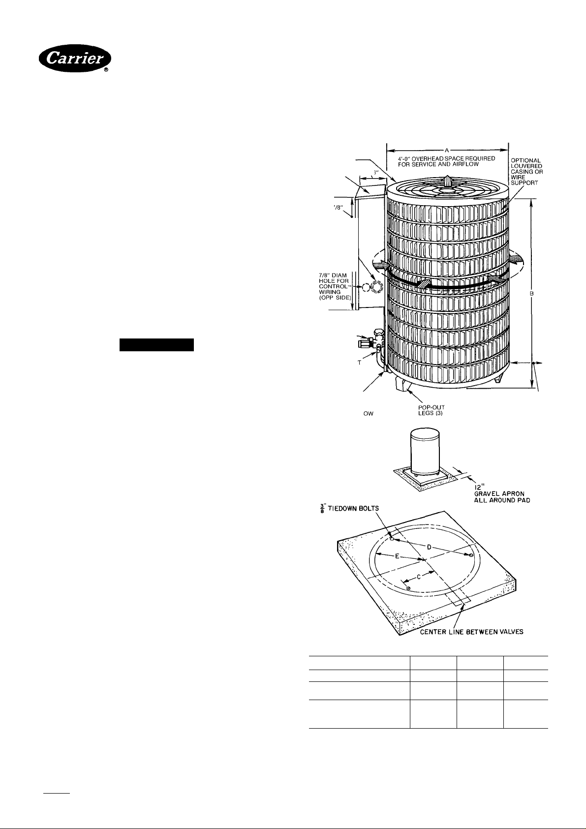
Step 1 — Check Equipment and Jobsite —
Install on a solid, level mounting pad. It is recommended
that unit be attached to pad using tiedown bolts. Fasten
unit to pad using holes provided in unit mounting feet.
See Fig. 1.
When installing, allow sufficient space for airflow
clearance, wiring, refrigerant piping and servicing. Main
tain a minimum of 4 ft clearance from obstructions above
and 18 in. on 3 sides of unit (12 in. on fourth side). Main
tain a distance of 24 in. between heat pumps. Position so
water or ice from roof or eaves cannot fall directly on unit.
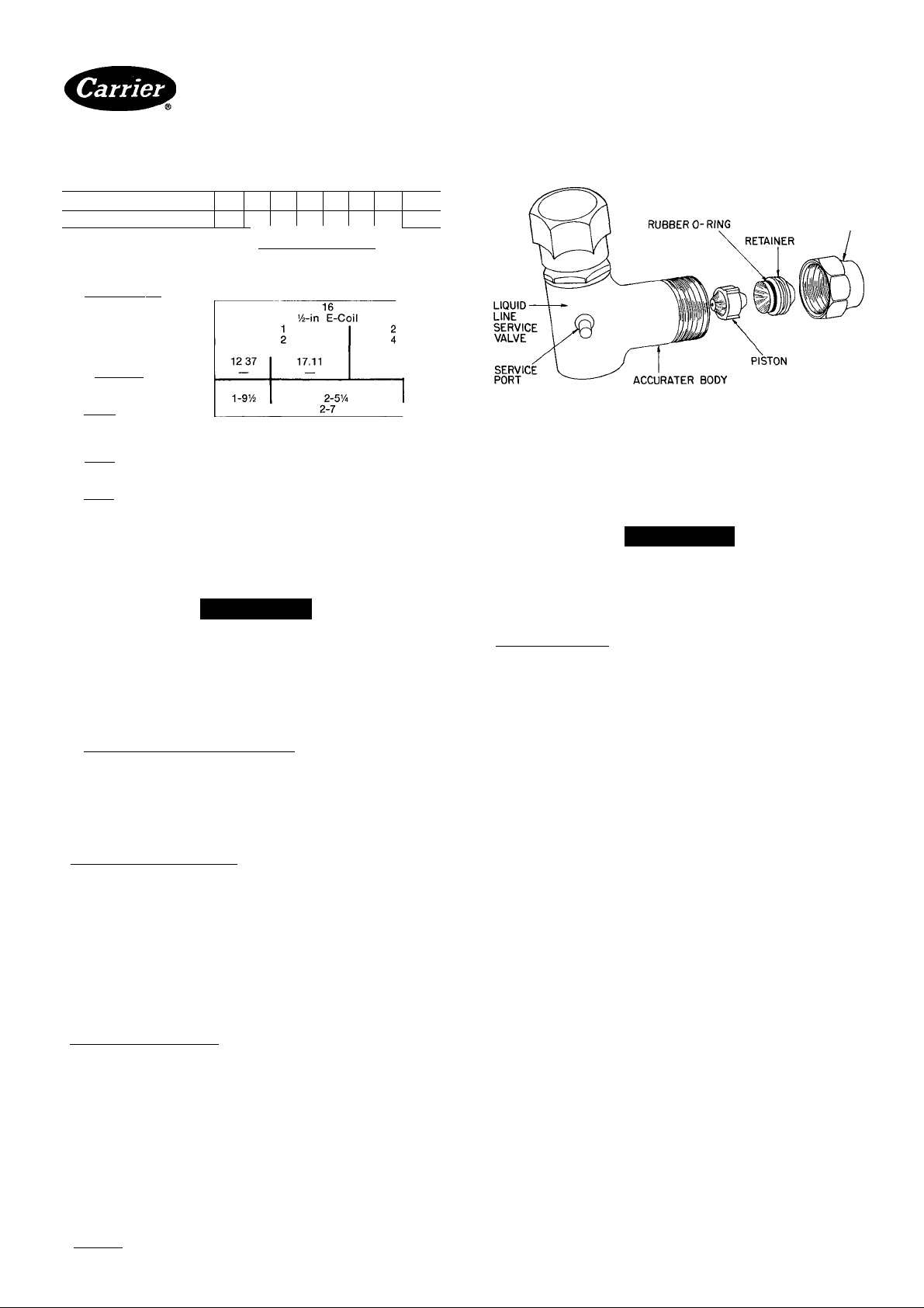
Step 2 — Replace AccuRater™ Refrigerant
Control Piston in the indoor coil, if required, before
conneeting refrigerant lines. See AccuRater Selection
Charts, Table 2.
Step 3 — Make Piping Connections — Outdoor
units may be connected to indoor sections using Carrier
accessory tubing package (refer to Service data) or field-
supplied tubing of refrigerant grade, correct size and
condition (Table 1). For tubing requirements beyond
50 ft, obtain information from local Carrier distributor.
Outdoor units connected to Carrier-approved indoor
units contain correct system refrigerant charge for opera
tion with indoor unit of the same size when connected by
25 ft of field-supplied or Carrier aceessory tubing. Check
refrigerant charge for maximum efficiency (refer to
Table 5 and Service data).
NOTE Mounting pad may be square or circular
MODEL 38QH
DIAMETERS (ft-in.)
SQUARES (Minimum)
(in.)
TIEDOWN BOLT C
LOCATION (tt-in.) D
015,018 024-048 060
1-9Y2 2-5'/4
23
o-ey. 0- 9'/2
1-4
E
0-9'/4 1-1
Fig. 1 — Dimensions, Connections and
Mounting Pad (Refer to Table 1)
30
1-10V2
3-3
40
1-1'=/i6
2-7
1-5ye
Manufacturer reserves Ihe right to discontinue, or change at any time, specifications or designs without notice and without incurring obiigations.
Bookll |4 PC 101 Catalog No 533-808 Printed inUS A Form38QH-2SI Pg 1 7-85 Replaces: 38QH-1 SI
Page 2
38QH
HEATING & COOLING
Table 1 — Physical Data
MODEL 38QH
OPER WT (lb)*
REFRIGERANT
Control
COND FAN
Air Discharge
AirQty (Cfm)
Mtr Rpm (60 Hz)
COND COIL (FIn/in.)
Tube Diam
Rows
Refrig Ckts
Face Area (sq ft)
Outer Row
Inner Row
DIMENSIONS (ft-in.)
Diameter
Height
CONNECTIONS (in. ODF)
Suction
Liquid_________________
REFRIG LINES (in. ODF)
Suction
Liquid________________
*Add 10 lbs for louvered casing (if so equipped). Weight increases slightly
with addition of any accessories
t38QFI042-060 require 1’/e-in. suction line for optimum performance. A
%- X I'/a-in connection adapter accessory (Carrier Part No 28AU900061)
is available. If a 7e-ln accessory tubing package is used, expect a 2'/2%
capacity loss
015 018
132 145 180 195 195 235
024 030 036 042 048
AccuRater” (Bypass Type)
Propeller Type, Direct Drive
1850 I 3100 I 4000 15000
830 850 840
Compatible Fitting (Suction)
1 y4
22
Vertical
& Flare (Liquid)
%
235
17.11 2188
17.11 21.88
I'/at
060
270
3-2'/2
A CAUTION
Heat Pumps.^^utdoor Section
FLARE NUT
Fig. 2 — AccuRater (Bypass Type) Components
4. Insert tube into Compatible Fitting until it bottoms.
Tighten nut until it bottoms on shoulder of fitting or
valve. Keep tube bottomed in Compatible Fitting
while tightening nut.
A CAUTION
If undersized, damaged or elliptically-shaped
tubing is used when making Compatible Fitting,
leaks may result.
DO NOT BURY MORE THAN 3 FT OF REFRIG
ERANT TUBING IN GROUND. If any section of
tubing is buried, there must be a 6-in. vertical rise to
valve connections on outdoor unit. If more than the
recommended length is buried, refrigerant may
migrate to cooler buried section during extended
periods of unit shutdown. This causes refrigerant
slugging and possibly compressor damage at start-up.
CONNECT REFRIGERANT LINES to fittings on out
door unit suction and liquid service valves (Fig. 1). Unit
Compatible Fittings permit mechanical (quick-connect)
or sweat connections.
Models 38OH042,048,060 — When using 1 -1 /8 in. fieldsupplied refrigerant suction line, sweat-connect suction
line to 1-1/8 in. end of required connection adapter. Be
sure to provide a heat sink at the service valve to prevent
damage during sweating operation. Connect 3/4-in. end
of adapter to unit suction line Compatible Fitting.
Connect liquid refrigerant line to unit. When a 7/8-in.
field-supplied suction line is used, provide a field-supplied
3/4-in. to 7/8-in. suction line adapter (not necessary if
38LS accessory tubing is used).
Mechanical Connection — Mate one set of connections at
a time.
1. Loosen nut on Compatible Fitting one turn. Do not
remove.
2. Remove plug and be sure O-ring is in the groove inside
the Compatible Fitting.
3. Cut tubing to correct length. Deburr and size as
necessary.
Sweat Connection— Use refrigerant grade tubing.
1. Remove locking nut, rubber O-ring and Schrader core
and cap from valve service port.
2. Cut tubing to correct length. Deburr and size as
necessary.
3. Insert tube in Compatible Fitting until it bottoms.
NOTE: Wrap top and bottom of service valves in wet
cloth to prevent damage by heat. Solder with lowtemperature 430 F silver alloy solder.
4. Replace Schrader core and cap.
5. Evacuate or purge system with field-supplied
refrigerant.
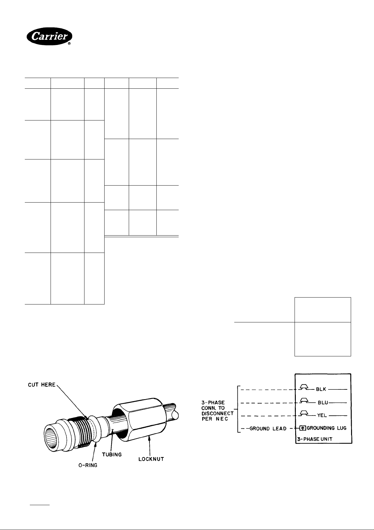
Compatible Fitting Repair
MECHANICAL CONNECTION — Frontseat unit
service valves. Relieve refrigerant pressure from tubing.
Back off locknut from Compatible Fitting onto tube. Cut
fitting between threads and O-ring. See Fig. 3. Remove
tubing section remaining in threaded portion of fitting.
Discard locknut.
Clean, flux and insert new tube end into remaining
portion of Compatible Fitting. Wrap valve in wet rag to
prevent damaging factory-made joints. Heat and apply
low-temperature (430 F) solder.
SWEAT CONNECTION — Frontseat unit service
valves. Relieve refrigerant pressure from tubing. Clean
and flux around leak. Repair, using low-temperature
(430 F) solder. Evacuate or purge evaporator coil and
tubing system. Add refrigerant charge. Refer to Table 5.
Manufacturer reserves the right to discontinue, or change at any time, specifications or designs without notice and without incurring obligations.
Book| 1 |4 PC101 Catalog No 533-808 PrintedinUSA Form38QH-2SI Pg 2 7-85 Replaces: 38QH-1 SI
©
X aK IAaIRa
For r<»nlacement items use Carrier Soecified Parts
Page 3
38QH
HEATING A COOLING
Heat Pumps — Outdoor Section
Table 2 — AccuRater™ Selection Charts
OUTDOOR
UNIT 38QH UNIT
015 40AQ018
(35)t
018
(42)t
024
(52)t
030
(59)t
036
(61 )t
'Replace factory-installed piston with this piston size
fRequired outdoor piston size
INDOOR
28AC015
28AC.AU018
28HQ.VQ024 49* 28AC.AU048 82*
40AQ024
40DQ014
40DQ018
40DQ024 49
28AC.AU018
28AC.au,AM024
28HQ.VQ024
28HQ.VQ030
40AQ018
40AQ024
40AQ030
40DQ018
40DQ024 52* 28AC260 86*
40DQ030
28AC,AU,AM024
28AC.AU030
28AM036
28HQ.VQ024
28HQ.VQ030
28HQ.VQ036
40AQ024
40AQ030
40AQ036
40DQ024 59
40DQ030 61*
28AC.AU030
28AC.AU036
28AC236
28AM036 70*
28HQ.VQ030
28HQ.VQ036
28HQ.VQ042
28SL030
28SL036
28SL042 73*
40AQ030
40AQ036 70*
40DQ030
28AC.AU036 73
28AC236
28AC.AU042 73’
28AC242
28AM036
28HQ.VQ036
28HQ.VQ042 73*
28HQ.VQ048 73*
28SL036
28SL042 73*
28SL048
40AQ036
40QB042 73’
INDOOR OUTDOOR
PISTON UNIT 38Qh
49‘ 28AC.AU042 80*
49’ 28AC242 80*
46
49* 28AM048
46*
46*
52*
55*
52*
55*
49*
52
55* 28AC248
49* 28AC.AU060
55* 28AM048
61*
63*
63*
59*
61*
63*
59*
61’
63*
70*
73
73
67*
70*
73*
67*
70*
67*
67*
73
73*
70*
70*
70*
73*
70*
842
(73)t
048
(73)t
060331
(78)t
060341
(78)t
INDOOR INDOOR
UNIT
28AC248 82*
28HQ.VQ042 76
28HQ.VQ048
28HQ.VQ060
28SL042
28SL060
40QB.QH048
28AC.AU048 84
28HQ.VQ048
28HQ.VQ060
28SL048
28SL060
40QB048
40QB.QH060
40QB.QH062
28AC.AU060
28AC260
28HQ.VQ060
28SL060 98*
40QB,QH060
40QB.QH062
28AC.AU060
28AC260
28HQ.VQ060 90*
28SL060
40QB.QH060
40QB.QH062
PISTON
82
80*
82*
76*
82*
82
84
86*
84*
82*
84*
82
84*
84*
86*
86*
101*
101*
98*
101*
101*
93*
93*
90*
93
93
Step 4 — Make Electrical Connections — Be
sure field wiring complies with local and national fire,
safety and electrical codes, and voltage to system is within
limits shown in Table 3. Contact local power company
for correction of improper line voltage.
NOTE: Operation of unit on improper line voltage con
stitutes abuse and could affect Carrier warranty. See
Table 3. Do not install unit in system where voltage may
fluctuate above or below permissible limits.
See Table 3 for recommended fuse sizes. When making
electrical connections, provide clearance at unit for refrig
erant piping connections.
INSTALL BRANCH CIRCUIT DISCONNECT PER
NEC of adequate size to handle unit starting current.
Locate disconnect within sight from and readily access
ible from unit, per Section 440-14 of National Electrical
Code (NEC).
ROUTE LINE POWER LEADS — Extend leads from
disconnect through power wiring hole provided (see
Fig. 1) and into unit splice area. Remove control box
cover to gain access to unit wiring.
CONNECT GROUND LEAD AND POWER WIRING
— Connect ground lead to ground connection in control
box for safety. Then connect power wiring. See Fig. 4.
Splice line power leads to yellow and black pigtails. Use
wire nuts and tape at each connection. Connect unit
wiring to copper power wiring only.
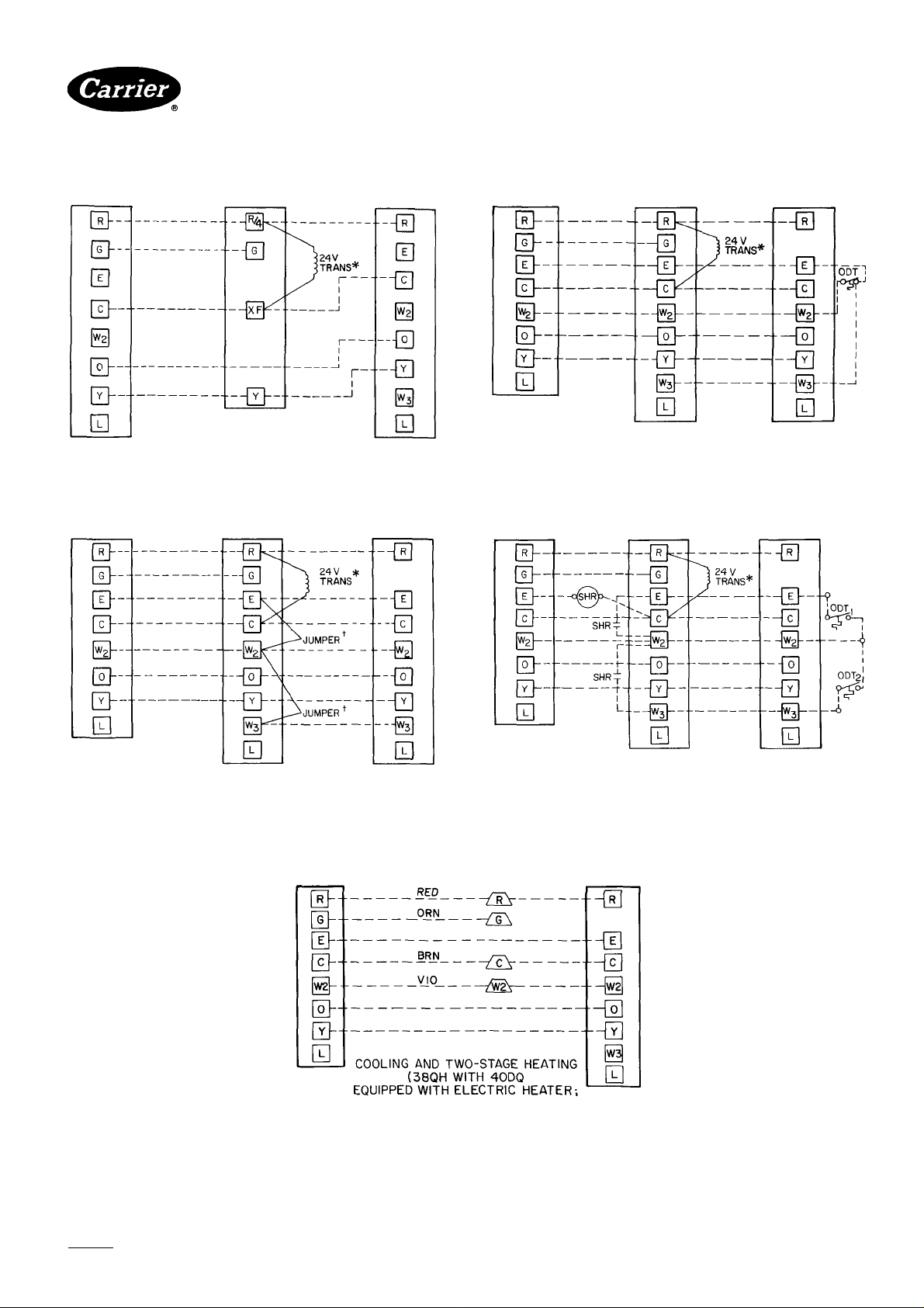
CONNECT CONTROL POWER WIRING — Route
24-v control wires through control wiring hole and
channel and eonnect leads to control wiring terminal
board. See Fig. 1 and 5.
Use furnace or fan coil transformer as 24-v (40-va
minimum) supply for system as shown in Fig. 5, or use
accessory transformer (refer to Service data).
--------
I-PHASE
CONN. TO
DISCONNECT
PER NEC
GROUND LEAD- -IUgrounding lug
_
----------------------------------
— YEL
1- PHASE
UNIT
COMPATIBLE FITTING
^ Splice Connections
_________
----------------
Fig. 3 — Compatible Fitting
Field Wiring
Factory Wiring
Fig. 4 — Line Power Connections
Manufacturer reserves the right to discontinue, or change at any time, specifications or designs without notice and without incurring obiigations.
Book|1 14 PC101 Catalog No 533-808 Printed in U.S A Form38QH-2SI Pg 3 7-85 Replaces: 38QH-1 SI
Tah IRaIRa
Fnr ronlnrAmAnl Home tieo f^orrior fino/^ilioH Dorte
Page 4
38QH
HEATING A COOLING
THERMOSTAT
SUBBASE
HH93AZI73
OR HH93AZ175
THERMOSTAT
SUBBASE
HH93AZI73
OR HH93AZI75
40AQ OR 40QB FAN COIL
COOLING CONTROL KIT
TERMINAL BOARD
COOLING AND ONE-STAGE HEATING
(38QH/40AQ 0R40QB WITHOUT ELECTRIC HEATER)
40AQ OR 40QB
ELECTRIC HEATER
TERMINAL BOARD
TERMINAL
Heat Pumps — Outdoor Section
3BQH
TERMINAL
BOARD
3BQH
BOARD
THERMOSTAT
SUBBASE
HH93AZI73
OR HH93AZI75
COOLING AND TWO-STAGE HEATING
(38QH WITH 40AQ, 40QB OR 40FS/28HQ, VQ
EQUIPPED WITH ELECTRIC HEATER;
SUPPLEMENTAL HEAT, ONE OUTDOOR THERMOSTAT)
THERMOSTAT
SUBBASE
HH93AZI73 OR
HH93AZI75
40AQ OR 40QB
ELECTRIC HEATER
TERMINAL BOARD
40AQ OR 40QB
ELECTRIC HEATER
TERMINAL BOARD
TERMINAL
38QH
TERMINAL
BOARD
38QH
BOARD
COOLING AND TWO-STAGE HEATING
(38QH WITH 40AQ,40QB OR 40FS/28HQ,VQ
SUPPLEMENTAL HEAT, NO OUTDOOR THERMOSTATS)
EQUIPPED WITI^ ELECTRIC HEATER;
В
THERMOSTAT HH07AT 171 40DQ ELEC.HEATER
WITHHH93AZI73(AUT0 (ALL MODELS) 38QH
CHANGEOVER) OR HH93AZI75 LOW VOLTAGE TERM. TERMINAL
(MAN. CHANGEOVER) SUBBASE SPLICE CONNECTIONS BOARD
ODT — Outdoor Thermostat
SHR — Supplemental Heat Relay
-------------
-------------
Factory Wiring
Field Wiring
SUPPLEMENTAL HEAT, NO OUTDOOR THERMOSTATS)
COOLING AND TWO-STAGE HEATING
(38QH WITH 40FS/28HQ,VQ
EQUIPPED WITH ELECTRIC HEATER;
SUPPLEMENTAL HEAT, TWO OUTDOOR THERMOSTATS)
*Transformer (60 va) located in cooling control kit or electric heater
tRemove factory-installed jumper (Connection B) when installing outdoor thermostats (ODT)
Fig. 5 — Control Circuit Connections
Manufacturer reserves the right to discontinue, or change at any time, specifications or designs without notice and without incurring obligations.
Book|1 |4 PC101 Catalog No 533-808 Printed in U S.A. Form38QH-2SI Pg4 7-85 Replaces:38QH-1 SI
Page 5

38QH
HEATING A COOLING
3-Phase Available with 030-060 Sizes (SM, DL Option Models)
OUTDOOR
UNIT 38QH
015301
018301
024301
030301
036301
042301
048301
060331
060341
030501
036501
042501
048501
060531
036601
042601
048601
060631
FLA — Full Load Amps
HACR — Heating, Air Conditioning, Refrigeration
LRA — Locked Rotor Amps
MCA — Minimum Circuit Amps
RLA — Rated Load Amps
V/PH
208/230/1
208-230/ЗФ
460/Зф
Heat Pumps — Outdoor Section
Table 3 — Electrical Data (60 Hz)
OPER VOLTS*
Max
254 187
245 187 74
506
Min
414
'Permissible limits of the voltage rangeât which unitwill operate satisfactorily
fTime-delay fuse.
|3-Phase available only with Deluxe and SM option units.
NOTE: Control circuit is 24 v on all units and requires external power source.
COMPR
LRA
35 7 1
50 8 0
54
78 14 5
86 7 14 9
107 4
110
130 25 9
142
59.5
65
92
32 8
37
46
FAN
RLA
12 9
18.3 1 9 27 3
20 4 1 9 29 9
31 2
10 6
11.5 .9 16 5
133
147
5 1
62
70
FLA
7
7
9
9 20
9 21 3
1 9
1 9
.9
9 19
1 9
Not Available
1 1
1.3
1 3
Not Ava
MCA
8 6 15
12 3 20
15 3 25
34 3 60
40 9
15 4
20 9
7.5
9 1
10.1
liable
BRANCH CIRCUIT
Max Fusef
or HACR Type
Ckt Bkr Amps
3 35
1 30
35
45
50
60
25
25
35
15
15
15
A WARNING
To avoid personal injury, be sure indoor blower has
stopped before attempting service or maintenance.
Heat Anticipator Settings for Room Thermo-
Stat(HH01AT171) — Set anticipator for room thermo
stat according to Table 4. These settings may be changed
slightly to provide a greater degree of comfort for a par
ticular installation.
Accessory Outdoor Thermostat provides adjust
able outdoor control of accessory electric heater. This
thermostat makes contact when a drop in outdoor tem
perature occurs. It energizes a stage of electric heat
when the outdoor temperature setting is reached, pro
vided the room thermostat is on the second stage of heat
ing. One outdoor thermostat is recommended for each
stage of electric heat after the first stage. Set the outdoor
thermostat(s) progressively lower for each stage. Refer
to heat load of building and unit capacity to determine
the correct outdoor thermostat settings.
The accessory supplemental heat relay is required when
2 outdoor thermostats are used. It is automatically ener
gized by the manually operated supplemental heat switch
in the indoor thermostat subbase. The thermostat locks
out compressor and the relay bypasses the outdoor
thermostats for electric heater operation during heat
pump shutdown. When one outdoor thermostat is used,
a supplemental heat relay is not required. The supple
mental heat switch in the indoor thermostat subbase
bypasses outdoor thermostat, locks out compressor and
activates electric heater.
MOUNT OUTDOOR THERMOSTAT in control box.
Attach brackets with short sheet metal screws to avoid
contact with coil. Leave capillary tube coiled in control
compartment making sure it is clear of all electrical con
nections and sharp metal edges.
MOUNT SUPPLEMENTAL HEAT RELAY in con
venient location on indoor unit. Attach with sheet metal
screw.
Table 4 — Thermostat Anticipator Settings
UNIT
38QH
015
018
024
030
036
042
048
060
FIRST-
STAGE
ANTICIPATOR
SETTING
Fixed
INDOOR
UNIT WITH
ELECTRIC
HEATER
40DQ and
40AQ Fan Coil
with 40AQ FItrs
or 40QB Fan Coil
with 40QB Htrs
HTR
kW
7 5
10.0
15 0
20 0
25.0
30 0
34.0
50
SECOND-
STAGE
ANTICIPATOR
SETTINGS
25
50
75
Manufacturer reserves the right to discontinue, or change at any time, specifications or designs without notice and without incurring obligations.
Booklll4 PC101 Catalog No 533-808 PrintedinUSA Form38QH-2SI Pg 5 7-85 Replaces: 38QH-1 SI
Tab I5al5a
For replacement Items use Carrier Specified Parts
Page 6
38QH
HEATING A COOLING
Heat Pumps — Outdoor Section
Step 5 — Start-Up
1. Energize crankcase heater a minimum of 24 hours
before starting unit. To energize heater only, set
thermostat at OFF position and close electrical dis
connect to outdoor unit.
2. Turn on main disconnect switch(es) to indoor and out
door units.
3. Set fan switch as desired (ON or AUTO.).
4. Set thermostat dial at desired temperature.
5. Set selector switch at HEAT or COOL. Operate unit
for 15 minutes.
6. Check system refrigerant charge. Refer to Table 5.
Motors and controls are designed to operate satis
factorily in the voltage range shown in Table 3. If neces
sary to use manifold gages for servicing, refer to Carrier
Standard Service Techniques Manual, Chapter 1, Refrig
erants, Page 1-5, Fig. 8 for bypass method of returning
charge to system. Removal of liquid line charging hose
without following these precautions could result in some
loss of charge.
Refrigerant Charging (See Fig. 6-21)
Table 5 — Service Data
MODEL
38QH
015
018
024 CRC2-0175-PFV 55
030
036
042
048
060
060341 H23A563ABCA 55
030 AV5532E 54
036
042
048
060
036
042
048
060
‘Factory refrigerant charge is adequate when indoor unit and outdoor unit
are the same size and are connected with 25 ft or less of field-tubing of
recommended size or Carrier accessory tubing
COMPR*
REZ3-0125-PFV 24
H22B173ABCA 40
AV5532E
AV5535H
AV5542H
AV5546H
WD60000AA
AV5535E
AV5542E 54
AV5546E 54
WY6000AA 76
AV5535E 54
AV5542E 54
AV5546E 54
WH6000AA 76
OIL CHG (oz)
Initial
54
54
54
54
76
54
Recharge
20 5 3 815
37
52 7 8 850
50
50
50
50 12 5 840
74
50
50 7 8
50 7 9
50
50 125 840
74
50 7 9 850
50
50
74
R-22
Chg* (lb)
5 5 815
7 8
79
11 0
14 1 840
140 840
11 0 840
14.1 840
11 0 840
125
14 1 840
OUTDOOR
FAN RPM
850
850
840
850
850
840
A CAUTION
To prevent personal injury, wear safety glasses and
gloves when handling refrigerant. Do not overcharge
system. This can cause compressor flooding.
Manufacturer reserves the right to discontinue, or change at any time, specifications or designs without notice and without incurring obligations.
Bookj 1 |4 PC101 Catalog No 533-808 Printed in U S A. Form38QH-2SI Pg 6 7-85 Replaces; 38QH-1 SI
Page 7
38QH
HEATING A COOLING
Heat Pumps — Outdoor Section
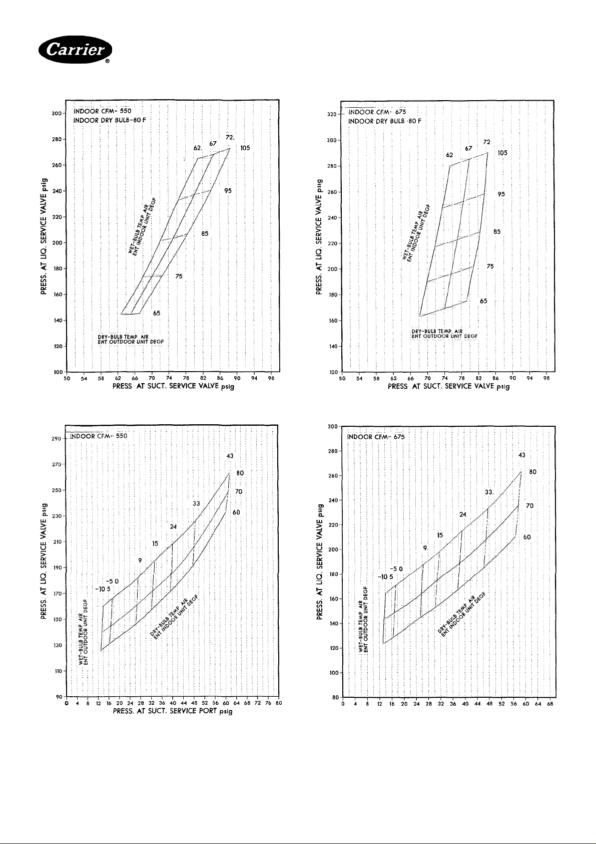
Fig. 6 — 38QH015 with Tabie 2 Combinations
Cooiing Cycle Charging Chart
Fig. 8 — 38QH018 with Tabie 2 Combinations
Cooiing Cycie Charging Chart
PRESS AT SUCT. SERVICE PORT psig
Fig. 7 — 38QH015 with Table 2 Combinations
Heating Cycie Check Chart
Manufacturer reserves the right to discontinue, or change at any time, specifications or designs without notice and without incurring obiigations.
Book11 |4 PC101 Cataiog No 533-808 PrintedinUSA Form 38QH-2SI Pg 7 7-85 Replaces: 38QH-1 SI
Tab I5al5a
For replacement items use Carrier Specified Parts.
Fig. 9 — 38QH018 with Table 2 Combinations
Heating Cycie Check Chart
Page 8

38QH
HEATING & COOLING
Heat Pumps — Outdoor Section
/■
Fig. 10 — 38QH024 with Table 2 Combinations
Cooling Cycle Charging Chart
Fig. 12 — 38QH030 with Table 2 Combinations
Cooling Cycle Charging Chart
PRESS AT suer SERVICE PORT psig
Fig. 11 — 38QH024 with Table 2 Combinations
Fig. 13 — 38QH030 with Table 2 Combinations
Heating Cycle Check Chart
Manufacturer reserves the right to discontinue, or change at any time, specifications or designs without notice and without incurring obligations.
Book|1 [4 PC101 Catalog No 533-808 PrintedinUSA Form38QH-2SI Pg8 7-85 Replaces; 38QH-1S)
Tab i5al5a
For replacement items use Carrier Specified Parts.
PRESS AT 5UCT. SERVICE PORT psig-
Heating Cycle Check Chart
Page 9
38QH
HEATING A COOLING
Heat Pumps — Outdoor Section
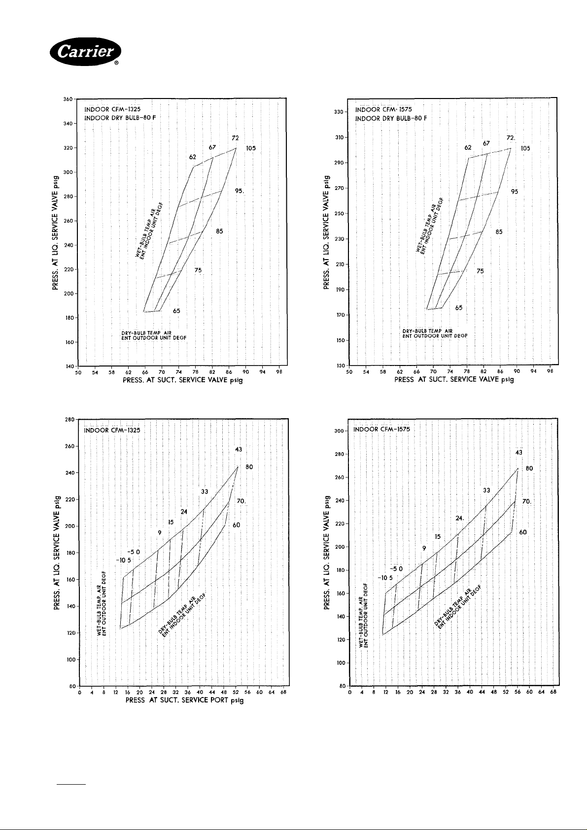
Fig. 14 — 38QH036 with Table 2 Combinations
Cooling Cycle Charging Chart
16 — 38QH042 with Table 2 Combinations
Fig,
Cooling Cycle Charging Chart
PRESS. AT SUCT. SERVICE PORT psia
Fig. 15 — 38QH036 with Table 2 Combinations
Heating Cycle Check Chart
Manufacturer reserves the right to discontinue, or change at any time, specifications or designs without notice and without incurring obiigations.
Book|1 |4 PC 101 Catalog No. 533-808 Printed inUS A Form38QH-2SI Pg9 7-85 Replaces: 38QH-1 SI
Tab l5al5a
For replacement items use Carrier Specified Parts.
Fig. 17 — 38QH042 with Table 2 Combinations
Heating Cycle Check Chart
Page 10

38QH
HEATING A COOUNG
Heat Pumps — Outdoor Section
Fig. 18 — 38QH048 with Table 2 Combinations
Cooling Cycle Charging Chart
-> Fig. 20 — 38QH060 with Table 2 Combinations
Cooling Cycle Charging Chart
PRESS. AT SUCT. SERVICE PORT psig
Fig. 19 — 38QH048 with Table 2 Combinations
Heating Cycle Check Chart
Manufacturer reserves the right to discontinue, or change at any time, specifications or designs without notice and without incurring obiigations.
Bool<n 14 PC 101 Catalog No 533-808 Printed inUS A Form38QH-2SI Pg 10 7-85 Replaces; 38QH-1 SI
Tabl5al5a For replacement Items use Carrier Specitled Parts.
Fig. 21 — 38QH060 with Table 2 Combinations
Heating Cycle Check Chart
 Loading...