

Page 1
38QE/40QE
KEATING A COOLING
Installation Instructions
TABLE OF CONTENTS
SAFETY CONSIDERATIONS
GENERAL OPERATION AND USAGE
APPLICATION LIMITATIONS
ORIENTATION AND LOCATION OF EQUIPMENT
Step 1 Inspect equipment and job site
Step 2 Install outdoor fan coil section (38QE924 or
38QE936)
Step 3 Install indoor compressor section (38QE024 or
38QE036) '
Step 4 Install domestic water heating control box
Step 5 Install domestic water heating tank temperature
fitting
Step 6 Install thermostat
Step 7 Install indoor fan coil (40QE024, 40QE036 or
40QEH036)
(refer to installation instruction supplied with
indoor unit)
Step 8 Install other accessories
PIPING CONNECTIONS
Step 9 Install refrigerant piping
Step 10 Install domestic hot water piping
ELECTRICAL CONNECTIONS
Step 11 Install control and sensor wiring
Step 12 Install thermostat wiring
Step 13 Install power wiring
SYSTEM SET-UP ADJUSTMENTS
Step 14 Inspect Indoor blower speed settings
Step 15 Adjust domestic water heating tank thermostat
settings
Step 16 Configure thermostats
Step 17 Adjust Refrigerant Charge
SAFETY CONSIDERATIONS
Installing and servicing air conditioning equipment can be
hazeurdous due to system refrigerant pressures and electrical
components. This is especially true with variable speed type
equipment, since HIGH VOLTAGE COMPONENTS
REMAIN ENERGIZED AFTER THE UNIT MAIN DIS
CONNECT IS OPENED!
Advanced Technology
Heat Pump System
For the above reasons, installation and servicing MUST BE
conducted only by a Carrier installer/dealer specifically
trained to service variable speed equipment. Improper
installation, adjustment, alteration, service, maintenance,
or use can cause explosion, fire, electrical shock or other
conditions which may cause personal injury or property
damage. Consult a qualified installer, service agency or your
distributor or branch for information or assistance. The
qualified installer or agency must use factory authorized
kits or accessories when modifying this product. Refer to
the individual instructions packaged with the kits or acces
sories when instalhng.
Follow all safety codes. Wear safety glasses and work
gloves. Use quenching cloth for brazing operations. Have
fire extinguisher available. Read these instructions thor
oughly and follow all warnings or cautions attached to<the
unit. Consult local building codes and NEC (National Elec
trical Code) for special installation requirements.
A WARNING
Before installing or servicing, turn off main power to
indoor and outdoor units. There may be more than one
disconnect switch. Turn off accessory heater power if
apphcable. Electric shock can cause personal injury or
death.
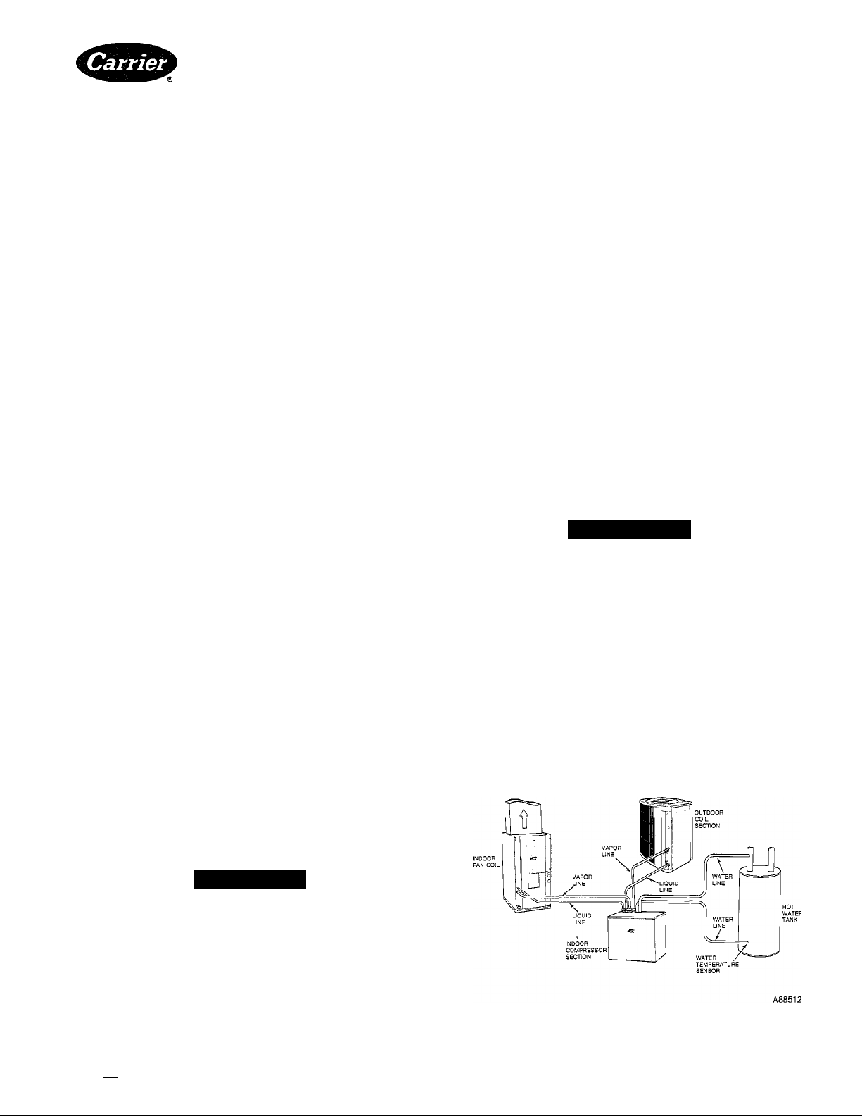
GENERAL OPERATION AND USAGE
The HydroTech 2000 advanced variable speed heat pump
system is designed to provide heating and cooling, as weU
as provide a majority of the year round domestic hot water
requirements. The system is composed of three main sec
tions, indoor compressor section, outdoor fan cofi. section
and the indoor fan coil section (see Fig. 1). Additionally a
A DANGER
A high-voltage (300-VDC) circuit remains energized
after the main disconnect is opened. The normal capaci
tive discharge time is 10 minutes, but this period may
be extended indefinitely by component failure. Before
servicing components within the compressor section
power box, always check with a DC voltmeter across
the D.C. Capacitor. Electrical shock can cause personal
injury or death.
Manufacturer reserves the right to discontinue, or change at any time, specifications or designs without notice and without incurring obiigations.
^ I PC 101 Catalog No. 563-964 Printed in U.S.A. Form 38QE-3SI Pg 1 5-90 Replaces: 38QE-2SI
Tab I5al5a
Fig. 1—38QE/40QE Advanced Heat Pump System
Page 2
domestic water heating control box emd domestic water
heating tank temperature sensor are supplied to control the
electric domestic water heating tank. The water heating is
accomphshed by pumping cold water from the cold water
inlet pipe at the top of the domestic water tank, through the
38QE refrigerant-to-water heat exchanger, and back into
the bottom of the tank.
The variable speed compressor operation allows the 38QE
system to control its output capacity to match the required
load through a wide range of outdoor temperatures and
operating modes.
Specially designed mating 40QE indoor units provide vari
able airflow control which is increased and decreased along
with the compressor speed. This feature, along with an elec
tronic expansion device, provide a level of comfort pre
viously unavailable for the home. It also enhances system
efficiency and provides much quieter operation them conventioneil systems during most periods of operation.
The 38QE/40QE system has many other designed in com
fort and efficiency features including:
Carrier/Parker Home-Zone® thermostat and damper
options—to provide separate temperature control in up to
four areas.
Humidity control—add the optional humidistat to activate
special compressor and fan control which improves moisture
removal as needed. Humidistat plus humidifier also controls
moisture addition in the heat mode.
Air cleaning—connections provided for automatic control of
optional electronic air cleaner.
Utility demand limit interface—allows owner participation
in incentive programs offered by utilities for peak load con
trol, where available.
Unique defrost—the high temperature of the water in the
home’s hot water tank is used as the heat source for the
defrost cycle, rather than cooling the indoor air as with tra
ditional units. In addition, demand type defrost control pro
vides defrost when, and only when, it is required.
The 38QE/40QE system is available in capacity sizes shown
in Table 1. Accessories supplied with the system and other
available accessories are shown in Table 2.
APPLICATION LIMITATIONS
The 38QE system software and safety devices Eire designed
to prevent equipment operation under conditions that do
not comply with the application hmitations.
The 38QE product has certEun application hmitations which
are hsted below:
The 38QE compressor section and outdoor section are
1.
to be matched to the specifically designed 40QE indoor
fan coil section. Permitted system configurations are
shown in Table 1.
Table 1—Carrier Approved 38QE Systems
SYSTEM CAPACITY
INDOOR COMPRESSOR SECTION 38QE024300 38QE036300
OUTDOOR FAN-COIL SECTION
INDOOR FAN-COIL SECTION
25 ft maximum vertical rise allowable
The 38QE can only be used with Carrier/Parker Home-
2.
2 TON 3TON
38QE924300 38QE936300
40QE024300 40QE036300
Zone® thermostats. Monitor thermostat and slave ther
mostat model requirements are given in Table 2. All
thermostats must be properly configured and pro
grammed in order to obtain normal system operation.
The 38QE should not be used with systems containing
3.
more than four (4) independently dampered zones. Use
<@)
of the bypass controUer accessory is required for aU
zone apphcations.
4. The system wiU not operate in the cool mode at outdoor
temperatures below 45 F, and is not compatible with
tie Carrier Motormaster low-ambient control
; accessory. /
5, §The systern wiU not operate in the heat mode at out
door ternperatures above 75 F.
The compressor section must be located in a non-
6.
freezing area because of water containing components.
Maximum air temperature surrounding the compressor
section must not exceed 105 F because of cooing
required for electronic controls.
The compressor section is designed to be installed on a
7.
sohd mounting pad such as concrete. Do not install
compressor section in an attic, on a wall, or suspended
from a ceiling.
Refrigerant line lengths are hmited to 50 ft total maxi
8.
mum, with 25 ft maximum vertical rise between indoor
and outdoor units.
9. For improved domestic water heating, locating the
compressor section within 15 ft of the domestic water
tank is desirable.
Table 2—Accessory Parts List
ACCESSORIES SUPPLIED WITH COMPRESSOR SECTION
ORDERING NUMBER
313204-701
313288-710
313243-201
ACCESSORIES REQUIRED OR RECOMMENDED
ORDERING NUMBER
HT2000
HZS (Version 2.7 or
higher)
ZD-06,08,10,12,14,16
RD0810,0814,0818,0824
BCE
TSR01
PS02/PS01
PSPOO
RDS
RRS
PCA-223
PCA-225
HL38MG026 Humidistat
—
__
38TH900011
38YH900011
38YH900021
P504-8163S
HT01AX220 Transformer 40va
RQ—Required for installations.
RC—Recommended for installations.
DESCRIPTION
Water Heater Control Box
Water Temperature Sensor
Assembly
Comp. Section Base Pad
Zones
DESCRIPTION Singl
Homezone Monitor Stat w/
clock RQ
Homezone Slave Stat RQ
Round Dampers 6" thru 16"
Rectangular Damper 8x10
thru 24
Bypass Controller
Relay Pack-Power Supply
Duct Pressure Sensor RQ
Static Pressure Plok-up RQ
Remote Duct Sensor OP
Remote Room Sensor OP
Plenum Cable—22 AWG, 3
conduc
Plenum Cable—22 AWG, 5
conduc
Humidifier (49BF/FH/WS) RC RC
Electronic Air Cleaner (31MPI
SX)
Outdoor Support Foot Kit, 4
in.
Outdoor Snow Rack, 18 in.
(024)
Outdoor Snow Rack, 18 in. OP
(036)
Bi-flow Filter-Drier
OP—Optional for installations.
Mult
RQ
RQ
RQ
RQ
RQ
OP
OP
)
RC RC
RC RC
RC
RC
RC RC
OP
OP
OP
OP
OP
RQ RQ
RQ
—
10. System is designed to work with conventional residen
tial sized electric water heating tanks only. NOTE: The
38QE should be installed with electric water heater
tanks that have two connections leading to the bottom
of the tank, as shown in Fig. 7a (cold water in, drain). If
only one connection to bottom of tank, install a preheat
tank, as for gas water heaters. Fig. 7b. For installation
with a gas water heater, a water preheat tank must be
installed.
i ;
Page 3
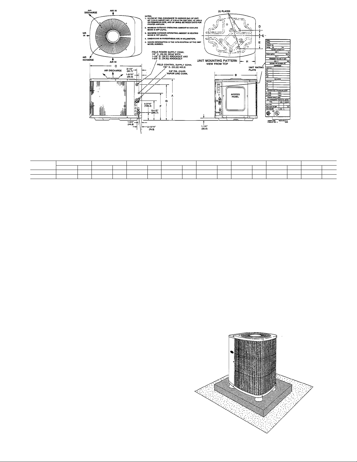
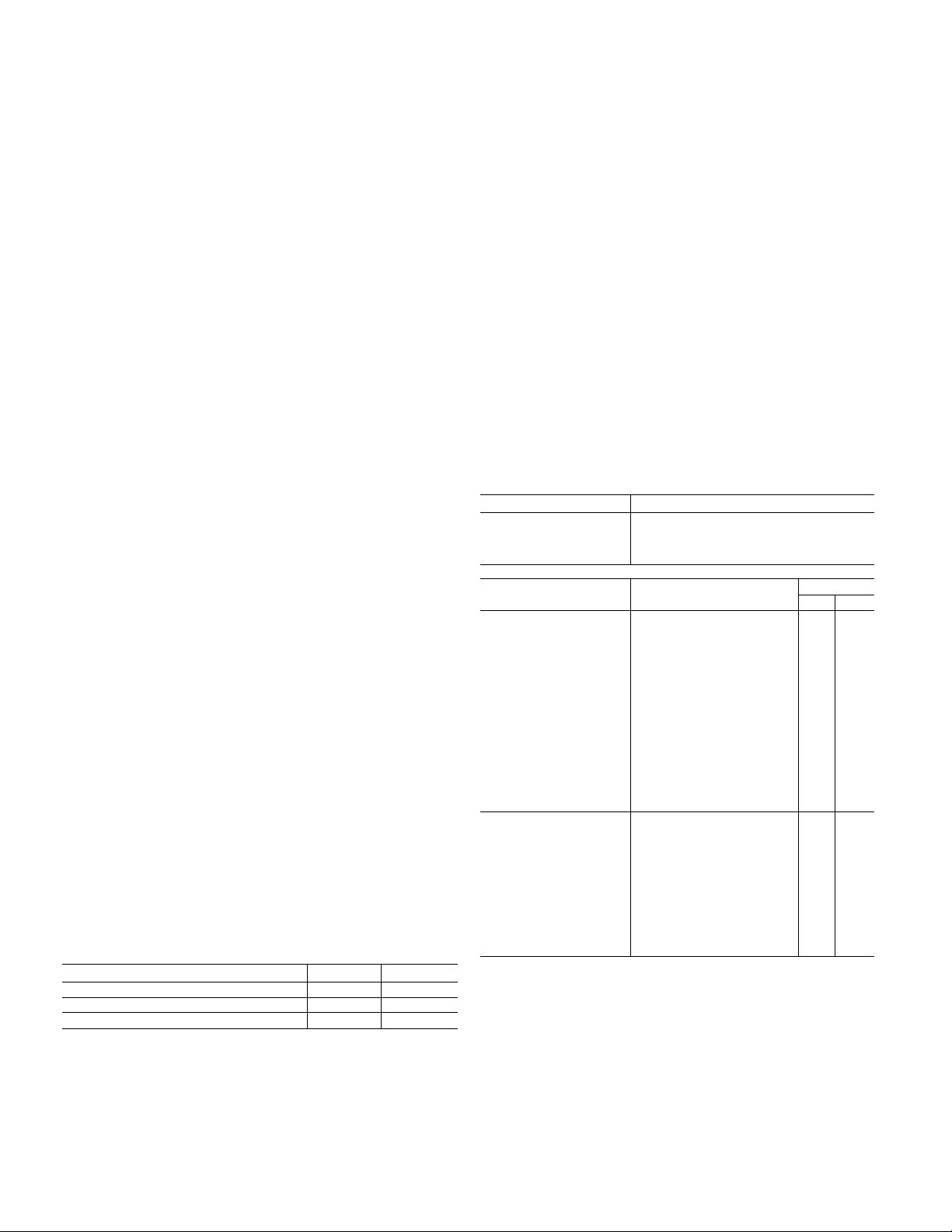
Fig. 2—Outdoor Section Dimensions
Dimensions
UNIT A B C D E
SIZE*
38Q E924
38Q E936 3 1-7/8 " 809 .6
(mm )
(IN.)
809 .6 30" 762.0 34 -15/1 6"
31-7/8" •
(IN.)
38-5/8"
(mm )
391 .0 45"
(IN.)
(mm )
887 .4
114 3.0
(mm )
(IN.)
4" 101 .6 9-3/4" 247 .6
5-15/16" 150.8
(IN.)
11-13/16 "
(mm )
300 .0 21-1 /2" 54 6.1 27-7/8" 7 08.0
F
(mm )
(IN.)
21-1/2" 546.1
G
(mm )
(IN.)
27-7/8" 708.0 8-3/16" 207 .9
A90214
H
(IN.) (mm )
8-9/16" 217.4
ORIENTATION AND LOCATION OF EQUIPMENT
Step 1—Inspect Equipment and Job Site.
A complete single zone system wül consist of the following:
1. Compressor Section
2. Outdoor Section
3. Indoor Section
4. Domestic Water Heater Control Box
5. Domestic Water Heater Tank Sensor
6. Homezone Monitor Thermostat
7. Homezone Power Supply Relay Pack
Unpackage and inspect imits for any damage. Füe claims
with shipper if necessary.
The compressor section package wül include an installation
packet, domestic water heater control box and tank temper
ature sensor.
The outdoor fan coü section will include an instaUation
packet. The indoor fan coü section wül include an instaUa
tion packet.
Consult local buüding codes and the National Electrical
Code (NEC) for special requirements.
When installing, aUow sufficient space for airflow clearance
(outdoor fan-coü section), wiring, refrigerant and water pip
ing and servicing unit. Position the outdoor section so water
or ice from roof cannot drop directly on top of unit. Position
the compressor section indoors and adjacent to the domes
tic water heating tank.
Step 2—Install Outdoor Fan-Coü Section (38QE924 or
38QE936).
The instaUation data, dimensions, and connection for the
38QE924,936 outdoor section are shown in Fig. 2.
InstaU on a solid, level mounting pad—If conditions or local
codes require the unit be attached to pad, tiedown bolts
should be used and fastened thru knockouts provided in
unit base pan. Refer to unit mounting pattern in Fig. 2.
Position so snow or ice from roof or eaves cannot faU
directly on unit. Position to minimize direct sunlight on air
temperature sensor above service valves.
On rooftop applications, locate unit at least 6 ins. above roof
surface. Place xmit above a load-bearing waU and isolate
unit and tubing set from structure.
Arrange supporting members to adequately support unit
and minimize transmission of vibration to buüding. Consult
local codes governing rooftop applications.
For proper drainage the outdoor section must be raised off
the mounting surface. Fig. 3 shows unit with accessory sup
port feet installed. Use accessory snow rack in areas where
prolonged subfreezing temperatures or heavy snow occur.
Refer to separate instaUation instructions packaged with
the accessories.
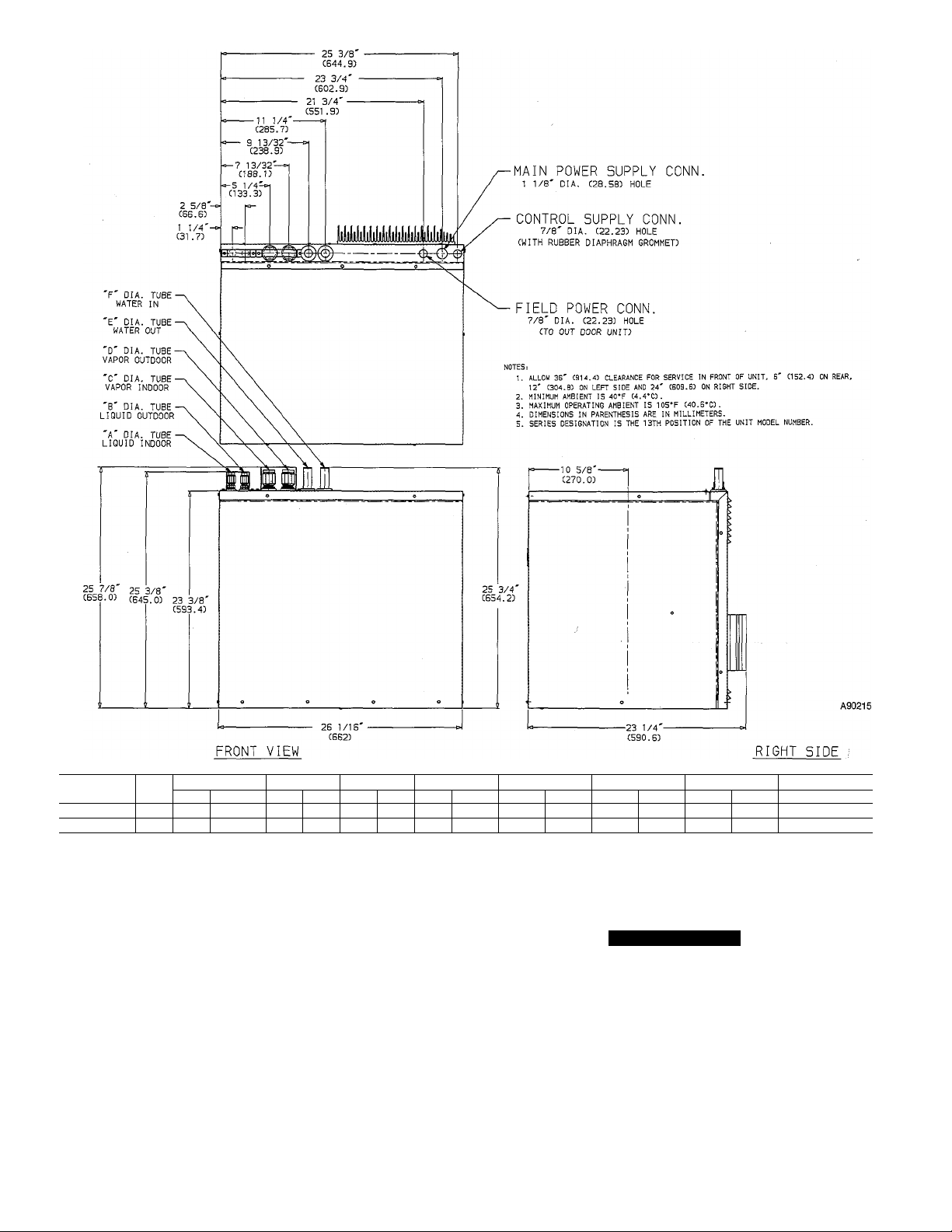
Step 3—Install Indoor Compressor Section (38QE024 or
38QE036).
The instaUation data, dimensions, and connection for the
38QE024, 036 compressor sections are shown in Fig. 4.
Locate unit in non-freezing area such as a basement, garage
or utility room. Indoor locations within the living space are
not recommended. Basement instaUations also require care
ful planning to avoid areas directly under or adjacent to
bedrooms, living rooms, etc. Locate unit near the domestic
water heater. AUow space for refrigerant and water piping.
A88277
Fig. 3—Outdoor Accessory Support Feet
Page 4
UNIT
38QE024
38QE036
SHIPPING WGT. A B
SERIES LBS.
230 104.3 3/8
0
0 240
108.8 3/8 9.53
Kg.
(IN.)
(mm)
9.53
(IN.) (mm)
3/8 9.53
3/8 9.53
C
(mm)
(IN.)
3/4 19.05
3/4 19.05 3/4
(IN.)
3/4
Fig. 4—Indoor Compressor Section
D
(mm)
19.05 7/8 22.23 7/8
19.05 7/8 22.23 7/8 22.23 38QE936
(IN.)
E
(mm) (IN.)
F
(mm)
22.23 38QE924
USE WITH
OUTDOOR SECTION
wiring and for servicing the unit (see Fig. 4). Do not exceed
maximum total pipe lengths.
Mount indoor compressor section on a rigid, sohd platform
or concrete floor. Insert the asphalt impregnated felt pad
(factory supplied in container) between the unit basepan and
moimting surface to provide fuU unit support and for vibra
tion attenuation. Do not use vibration isolators under cor
ners of basepan.
Install unit to permit adequate clearance for service on all
sides of the unit. A heat sink which is used to provide elec
tronic component cooling is located at the lower right side
of the rear panel. This heat sink protrudes from the rear
panel. This area should always remain clear of obstructions.
Do not enclose this area, in any manner. Failure to provide
proper ventilation can cause equipment to malfunction.
A CAUTION
To prevent freezing of water piping, do not expose the
38QE indoor compressor section to ambient tempera
tures below freezing.
Step 4—Install Domestic Water Heater Control Box.
The domestic water heater control box allows the 38QE
heat pump to control the domestic water heating function.
The tank elements are controlled by the 38QE such that the
water heating is performed by the heat pump when possible
and the tank elements are disabled.
Locate the control box adjacent to the Domestic water heat
ing tank. The box will be wired in the branch circuit that
»!
Page 5

supplies the power for the Electric Water Heater Tank. Con
trol and sensor wiring will also be connected to the control
box. Refer to wiring section of this manual for description of
the wiring required.
Step 5—Install Domestic Water Heating Tank Tempera
ture Sensor Fitting.
The tank temperature sensor is used to provide the 38QE
with the tank water temperature. This temperature is used
to control and terminate the water heating mode.
The water temperature sensor fitting is installed into the
tank drain-out fitting. Details describing the piping are con
tained within the piping section of this manual.
Step 6—Install the Thermostat(s).
The system is designed to operate with Carrier/Parker
Home-Zone® model thermostats and zoning deunpers. Refer
to the installation instructions shipped with the Carrier/
Parker Home-Zone® accessories.
Step 7—Install Indoor Fan-Coil Section (40QE024,
40QE036 or 40QEH036).
Refer to the installation instruction shipped with the 40QE
unit.
Step 8—Install Other Electrical Accessories, if any.
Refer to the individual instructions packaged with optional
accessories (humidistat, humidifier, air cleaner, zone ther
mostats and dampers).
Also refer to the installation instructions supplied with the
40QE indoor unit.
PIPING CONNECTIONS
A system piping schematic is shown in Fig. 5 which illus
trates both the refrigerant and domestic water heating con
nections that are required.
Isolate interconnecting tubing from the framing and duct
work or where tubing runs through stud spaces, enclosed
ceiling or pipe chases. Use isoiation type hangers, since
rigid fastening transmits pulsation to structure, creating
objectionable sound.
Step 9—Install Refrigerant Pipes
NOTE: Before making the 3/8" O.D. refrigerant line connec
tions at the indoor coil verify that the fittings do not con
tain an AccuRater piston.
The 38QE system employes a unique electronic bi
directional expansion valve, located within the compressor
section, and does not require AccuRaters in either the
indoor or outdoor section..
Refrigerant piping between sections may be made using
accessory tubing packages or field-supplied tubing of refrig
erant grade, correct size and condition.
If either refrigerant tubing or unit piping is exposed to
atmospheric conditions for longer than 5 minutes, it must
be evacuated to 1000 microns to eliminate contamination
and moisture in the system.
All refrigerant tubes must be insulated with closed-ceU foam
type insulation with a minimum waU thickness of 3/8". Fail
ure to properly insulate refrigerant tubes adequately wUl
degrade system performance and efficiency, as well as per
mitting moisture or frost to form on the tubing surfaces
during some operating modes. Insulation on the refrigerant
lines at the compatible fittings should extend over the com
patible fitting to prevent moisture from collecting on the
fitting surface and freezing during low outdoor temperature
operation. Freezing of the moisture on the compatible fit
ting may cause damage to the fitting and refrigerant
leakage.
Run refrigerant tubes as directly as possible, avoiding
unnecessary turns and bends. Suspend refrigerant tubes so
they do not damage insulation on liquid and vapor tubes
and do not transmit vibration to structure. Also, when pass
ing refrigerant tubes through walls, seal opening so vibra
tion is not transmitted to structure. Leave some slack in
refrigerant tubes between structure and units to absorb
vibration.
A CAUTION
DO NOT BURY MORE THAN 3 FT OF REFRIGER
ANT TUBING IN GROUND. If any section of tubing
is buried, there must be a 6-in. vertical rise to valve con
nections on outdoor unit. If more than the recom
mended length is buried, refrigerant may migrate to the
cooler buried section during extended periods of shut
down. This causes refrigerant slugging and possibly
compressor damage at start-up.
Compressor Section
Refrigerant piping on the 38QE differs from other Carrier
triple split type systems. The refrigerant piping requires the
installation of two (one 3/4-in. O.D. copper tube and one
3/8-in. O.D. copper tube) tubes between the compressor sec
tion and each of the indoor and outdoor sections. A filterdrier, specified in Table 2 or supplied with unit, must be
installed in the 3/8-in. indoor liquid fine within 12 ins. of the
compressor section for noise control. Fig. 5 illustrates the
various refrigerant tube connections on the compressor
section.
3/4-in. O.D. refrigerant vapor tube to indoor coil
3/4-in. O.D. refrigerant vapor tube to outdoor coü
3/8-in. O.D. refrigerant liquid tube to indoor coil
3/8-in. O.D. refrigerant liquid tube to outdoor coü
The total refrigerant fine distance from the indoor fan coü to
the outdoor unit shaU not exceed 50 equivalent ft (see
Fig. 6).
Both the liquid and vapor connections have compatible fit
tings. Compatible fittings permit mechanical (quickconnect), or sweat connections.
A. Mechanical connection (mate one set of connections at a
time.)
1. Loosen nut on compatible fitting one turn. Do not
remove.
2. Remove plug and be sure 0-ring is in groove inside
compatible fitting.
3. Cut tubing to correct length. Deburr and size as
necessary.
4. Insert tube into compatible fitting untü it bottoms.
TIGHTEN NUT UNTIL IT BOTTOMS ON SHOUL
DER OF FITTING OR VALVE. Keep tube bottomed
in compatible fitting whüe tightening nut. Do not over
tighten.
A CAUTION
If undersized, damaged or eUiptically-shaped tubing is
used when making Compatible Fitting, leeiks may
result.
B. Sweat connection—Use refrigerant grade tubing.
1. Remove locknut, and rubber 0-ring from inside of com
patible fitting.
2. Cut tubing to correct length.
3. Insert tube into compatible fitting until it bottoms.
Page 6

A89059
(Top)
Fig. 5—38QE/40QE System Piping Schematic
A89059
(Bottom)
Fig. 6—Maximum Refrigerant Line Length
4. After wrapping the service valve with a wet cloth, the
tubing set can be brazed to the service valve using
either silver bearing or non-silver bearing brazing
material. Consult local code requirements.
Outdoor Fan Coil Section
Jk CAUTION
A brazing shield MUST be used when tubing sets are
being brazed to the service valves to prevent damage to
the painted unit surface.
A CAUTION
To avoid damage while brazing, service valves must be
wrapped with a heat-sinking material such as a wet
cloth.
Both the liquid emd vapor lines require sweat connections.
Use proper equipment and safety precautions when making
the sweat connection. The service valves on this unit are
both front and backseating. The service port does not con
tain a Schrader fitting. Do not attempt to connect manifold
until valve is fully backseated.
Service valves are closed from factory and ready for braz
ing. After wrapping the service valve with a wet cloth, the
tubing set can be brazed to the service valve using either sil
ver bearing or non-silver bearing brazing material. Consult
local code requirements.
Outdoor units contain correct system refrigerant charge for
operation with indoor unit of the same size when connected
by 25 ft of field-supplied or factory accessory tubing. Check
refrigerant charge for maximum efficiency (see Refrigerant
charging).
Indoor Fan Coil Section
The liquid and vapor tube fittings are flare and compatible,
respectively on the 40QE units. Use proper equipment and
safety precautions when making the flare connections.
Refer to the 40QE Installation Instructions.
Step 10—Install Domestic Hot Water Piping
A CAUTION
Use only water piping, fittings and brazing material
that are suitable for Potable Water systems when con
necting the heat pump to the household water system.
Consult local codes.
The compressor section and domestic water heater should
be located as near as possible to each other. Total length of
interconnecting water piping between the compressor sec
tion and water heater should not exceed the lengths shown
in Table 3. The number of bends and pipe fittings should be
kept to a minimum. The use of shut-off valves in the water
lines between the domestic water tank and the compressor
section are not recommended as they may adversely affect
the system performance. (If valves are used, use only Ball or
Gate type). However compliance with local codes should be
followed. Failure to insulate pipes will result in performance
degradation..
Domestic Water Heating Tank
The 38QE can be installed with a conventional electric
water heater or with a gas water heater system. The basic
installation procedures are the same. However in the instal
lation with the gas water heater an insulated preheat tank
Table 3—Recommended Water
Piping Size
PIPE SIZE
1/2" nom (5/8" OD)
3/4" nom (7/8" OD) 50
♦Length can increase by 1.6 ft for each elbow less than 6.
♦♦Length can increase by 2.0 ft for each elbow less than 6.
tTotal length of cold and hot water pipes.
ALLOWABLE TOTAL
PIPING LENGTH (Ft)t
20
ALLOWABLE TOTAL
PLUS
PIPING ELBOWS
6^
6**
must be used. The preheat tank is essentially an electric
water tank without the electric heating elements.
Installation of the 38QE with a conventional electric water
heater is shown in Fig. 7a. Installation with a gas water
heater and preheat tank is shown in Fig. 7b.
Tank Water Temperature Sensor
The connection of the water heating lines to the tank
includes the installation of the tank water temperature sen
sor. The tank water temperature sensor is located within the
drain fitting of the tank. The fitting location is shown in
Fig. 7a,b. The detail for instaUing the sensor is shown in
Fig. 8.
Water connection tubes on the 38QE compressor section are
identified in Fig. 4. The two tubing stubs require fieldsupplied sweat couplings or reducing couplings for connec
tion to water lines.
A CAUTION
A brazing shield must be used when tubing and fittings
are being brazed to the water stub tubes to prevent
damage to the painted unit surface.
Page 7

Fig. 7a—Installation with Conventional
Electric Water Heater
7. Insulate all water pipes with closed-cell foam type insu
lation with a nunimum wall thickness of 3/8 in.
8. If shut off valves have been installed in the water lines
between the tank and compressor section, slowly open
all valves. Bleed air from the heat pump water circuit
and circulating pump. First loosen the threaded union
on the pump outlet untU water flows out and no air is
present. Retighten union. Repeat process with xmion on
pmnp inlet. Then loosen air bleed screw in the center of
the circulating pump. The air bleed screw should only
be loosened, not totally removed, enough to allow air to
bleed. Retighten screw after system has been bled.
A CAUTION
Failure to bleed air from the water pump before energiz
ing will cause immediate pump failure. The pump
employs water-cooled and lubricated bearings; and if air
is left in the vicinity of the bearing, insufficient cooling
and lubrication will be available and bearing failure will
result.
ELECTRICAL CONNECTIONS
NOTE: This equipment generates and uses radio frequency
energy. If not installed properly in strict accordance with
these installation instructions, it may cause interference
with televisions and/or radio reception. It has been tested
and foxmd to comply with the limits for a Class B comput
ing device in accordance with the specifications in Subpart
J of Part 15 of FCC rules (which are designed to provide pro
tection against such interference in a residential installa
tion). However, there is no guarantee that there will not be
interference in a particular installation. If this equipment
does cause interference to television and/or radio reception,
which can be determined by turning the equipment off and
on, the installer or serviceman should refer to “38QE Start
up, Troubleshooting and Service Guide.”
Fig. 7b—Installation with Gas Water Heater
and Preheat Tank
Tank Water Temperature Thermostat
Adjust the lower electric heater thermostat to the minimum
setting.
Water Piping Installation
1. Shut off all electrical power to domestic water heater.
2. Shut off water supply to domestic water heater and
drain tank.
Remove drain valve from bottom of tank which
3.
requires sensor (Fig. 7a or 7b). Install pipe nipples and
tee and insteJl tank water temperature sensor as shown
in Fig. 8. Bend sensor up to avoid hitting water tanks
that have dome shaped bottoms.
4.
Install second tee into tank sensor tee as shown in
Fig. 8. Install drain valve and connect water piping
between second pipe tee and hot water outlet connec
tion on the compressor section.
5. Install a tee fitting on the cold city water supply as
shown in Fig. 7. Install the water piping between the
tee fitting and the cold water inlet connection on the
compressor section.
6. Refill the hot water pipes and tank, purge air, and
check aff water connections for leaks.
HOT WATER FROM 38QE
COMPRESSOR SECTION
Fig. 8—Hot Water Inlet Connection
to Hot Water Tank
A90213
Page 8

Compressor section to indoor fan coil section ;
38QE
Compressor Section
Terminal Board
Compressor section to outdoor fan coil section:
38QE
Compressor Section
Terminal Board
0
0
40QE
Indoor Section
Terminal Board
38QE
Outdoor Section
Terminal Board
0
"0
0
Domestic water heater control box and temperature sensor (Electric water heater)
Water Heater
Control Box
Terminal Board
Water Temperature
Sensor
A
0.
0
0-
-
0
Water Temperature Sensor (Gas water heater and preheat tank)
38QE
Compressor Section
Terminal Board
0
0
(w^
0
38QE
Compressor Section
Terminal Board
A
0
Water Temperature
Sensor
0.
0
A
Splice Connection
-- Field Wiring
~ Factory Wiring
Fig. 9—System Control and Sensor Connections
8
0
0
Page 9

A CAUTION
Avoid running control and sensor wiring in parallel
bundles, conduit or pipe chases with the power wiring.
Power wiring can cause interference with the control
and sensor wiring. Maintain a minimum of 6 ins. of sep
aration between the control and sensor and power wir
ing. Control wiring should be secured to the refrigerant
piping between the compressor, indoor and outdoor
units.
A CAUTION
To prevent interference avoid running control and sen
sor wires in parallel with antenna emd telephone cables.
IMPORTANT: The use of aluminum wire for any power or
control wiring is not allowed, all electrical wiring must be
copper; and all wiring specifications pertaining to the 38QE
system are specified as copper wire using American Wire
Gauge (AWG) sizing system
Step 11 —Install Control and Sensor Wiring
The control wiring consists of connections between the com
pressor section, water heater control box, indoor fan coil
and the thermostat. Sensor wiring is connected between the
outdoor fan coil and the compressor section. Sensor wiring
is also connected between the water heater tank and the
domestic water heating control box.
Control and sensor wiring requires standeird "thermostat
type and gauge of wire. The plenum cable listed in Table 2 is
recommended.
Compressor Section to Indoor Fan Coil Section
Run one length of 3 conductor wire. See Fig. 9 for connec
tion schematic. These three wires are used to control com
munications. To reduce the possibihty of electrical interfer
ence, route this cable along the refrigerant tubes and attach
with wire ties.
Compressor Section to Outdoor Fan Coil Section
Run one length of 3 conductor wire. See Fig. 9 for connec
tion schematic. These wires are used for outdoor unit tem
perature sensors. To reduce the possibility of electrical
interference, route this cable along the refrigerant tubes and
attach with ties.
Domestic Water Heater Control Box to Compressor Section
Run one length of 4 conductor wire. See Fig. 9 for connec
tion schematic. Two wires will be used to power the water
heater contactor. The other two wires will be used for the
tank sensor connections. Do not interconnect the contactor
and sensor wires as immediate damage will result.
Domestic Water Tank Temperature Sensor to Water Heater
Control Box
See Fig. 9 for connection schematic. Use 2 conductor wire, if
extra length is required to make the connection.
NOTE: For installations with a gas hot water heater and a
preheat tank, the water heater control box may be omitted.
Wire tank water temperature sensor directly to compressor
section as shown in Fig. 9.
Step 12—Install Thermostat Wiring
The thermostat connections are described below for both
single and multiple zone installations.
The single zone instaRation requires a Parker relay pack
power supply accessory to provide power for the single zone
thermostat.
Single Zone—Fig. 10
Connect 3 wires from indoor fan coil section to monitor ther
mostat. Connect 5 wires from thermostat to power supply
module. Connect 2 wires from the power supply module to
the indoor fan coU section terminals R and C or an auxiliary
transformer that is capable of supplying 24 VAC. These
connections are shown schematically in Fig. 10. AH connec
tions within the indoor fan coU are described in the 40QE
Installation Instructions.
Multiple Zone (option)—Fig. 11
Connect 3 wires from indoor fan coil section to Monitor
Thermostat. AU additional zones are to be connected as
shown in Fig. 11 in parallel. All connections within the
indoor fan con and for each additional zone are described in
the 40QE Installation Instructions.
Other Accessories
Refer to the individual instructions packaged with optional
accessories for their control wiring. Also refer to the instal
lation instructions supplied with the 40QE indoor unit.
Step 13—Install Power Wiring
The 38QE system requires three branch circuits for power.
These include the compressor section, domestic water
heater and the indoor fan coil. The outdoor fan coil section
receives power from the indoor compressor section. The
electrical data for the 38QE system is shown in Table 4.
NOTE: Be sure field wiring comphes with local emd national
fire, safety and electrical codes, and voltage to system is
within limits shown in Table 4 or on unit rating plate. Con
tact local power company for correction of improper volt
age. See Table 4 for recommended circuit protection device.
NOTE: Operation of unit on improper line voltage consti
tutes abuse and could affect unit reliability. Do not install
unit in system where voltage may fluctuate above or below
permissible limits.
Install all branch circuits and disconnect switches in accord
ance with National Electric Codes (NEC) and appMcable
local codes. Locate disconnect(s) within sight from and read
ily accessible from the unit, per section 440-14 of the
National Electric Code (NEC).
208 Volt Operation
Model 38QE and 40QE units are factory wired for nominal
Page 10

TSR-01 Relay Pack Circuit Board
24 VAC
R and C on
'40QE
Terminal
Board
Fig. 10—Thermostat Wiring Diagram
(Singie Zone)
Fig. 11—Thermostat Wiring Diagram
(Multipie-Zone)
10
A89057
Page 11

Table 4—Electrical Data
OPERATING
INDOOR COMPRESSOR SECTION
38QE024300 208/230/1
38QE036300 208/230/1 187 254
OUTDOOR FAN-COIL SECTION
38QE924300 208/230/1
38QE936300 208/230/1 187 254
WATER HEATER CONTROL BOX
38QE9XX300 208/230/1 187 254 20 20
FLA —Full Load Amps
HACR—Heating, Air Conditioning and Refrigeration
MCA —Minimum Circuit Amps
RLA —Rated Load Amps
LRA —Locked Rotor Amps
VOLT/PHASE
VOLT AG £♦
MIN
187 254
187
MAX
254 .5
♦Permissible limits of the voltage range at which the unit will operate
satisfactorily.
♦♦Outdoor Coil Wiring—For 25-ft wire run or less, use minimum 14 AWG
wire size. For longer wire run, use same size wire as supply to compres
sor section.
COMPRESSOR FAN
LRA
35.0
35.0 25.3 50
RLA FLA
20.3 40
.7
MAX FUSE or
HACRTYPE
CIRCUIT BKR
AMPS
MCA
25.9
32.4
230 V operation. The primary connection on control trans
formers must be rewired to the 208 volt wires for line volt
age between 187 emd 218 Volts. Refer to the 38QE Compres
sor Section label wiring diagram for location and wire identi
fication to rewire the two (2) transformers in the main con
trol box. Refer to the 40QE label wiring diagram for loca
tion and wire identification to rewire the transformer in the
accessory heater or cooling-only control package. Cap each
unused transformer wire with a wire nut and tape or, if the
unused lead has a push-on terminal, tape and protect any
exposed metal on the terminal.
Compressor Section
InstaR branch circuit disconnect of adequate size to handle
compressor section. Route line power leads from disconnect
through hole provided in compressor section top rear panel
and into the main control box. Connect ground wire to
ground lug. Connect main power to the terminal block
located within the main control box. The compressor section
wire label illustrates the terminal block location.
Rear panel wiring holes are shown in Fig. 4. See Fig. 12 for
connection schematic.
38QE Compressor
Section Control Box
Outdoor Fan Coil Section
The outdoor fan coil section receives power from the com
pressor section. Provide a separate disconnect switch for
the outdoor fan cofi. section. Fig. 12 illustrates the connec
tions from the compressor section to the disconnect switch
and then to the outdoor fan coil section.
Connect ground wire to ground lug. Route power wires for
the outdoor fan coil section through the 7/8-in. hole provided
in the top rear panel of the compressor section. Splice wires
to pigtails with wire nuts.
Connect the power wires to the outdoor disconnect switch.
From the disconnect switch, extend wires through hole pro
vided in outdoor fan coil section and into line voltage sec
tion of control box. Splice leads to black and yeUow pigtails
with wire nuts. Connect ground wire to ground lug inside
control box.
Domestic Water Heater Control Box (Electric Heater Only)
Install branch circuit disconnect of adequate size to handle
domestic water heater. Fig. 13 illustrates the required wir
ing connection between the branch disconnect and the 38QE
Splice Connection
Field Wiring
Factory Wiring
Fig. 12—Compressor Section and Outdoor
Section Power Connections
11
Page 12
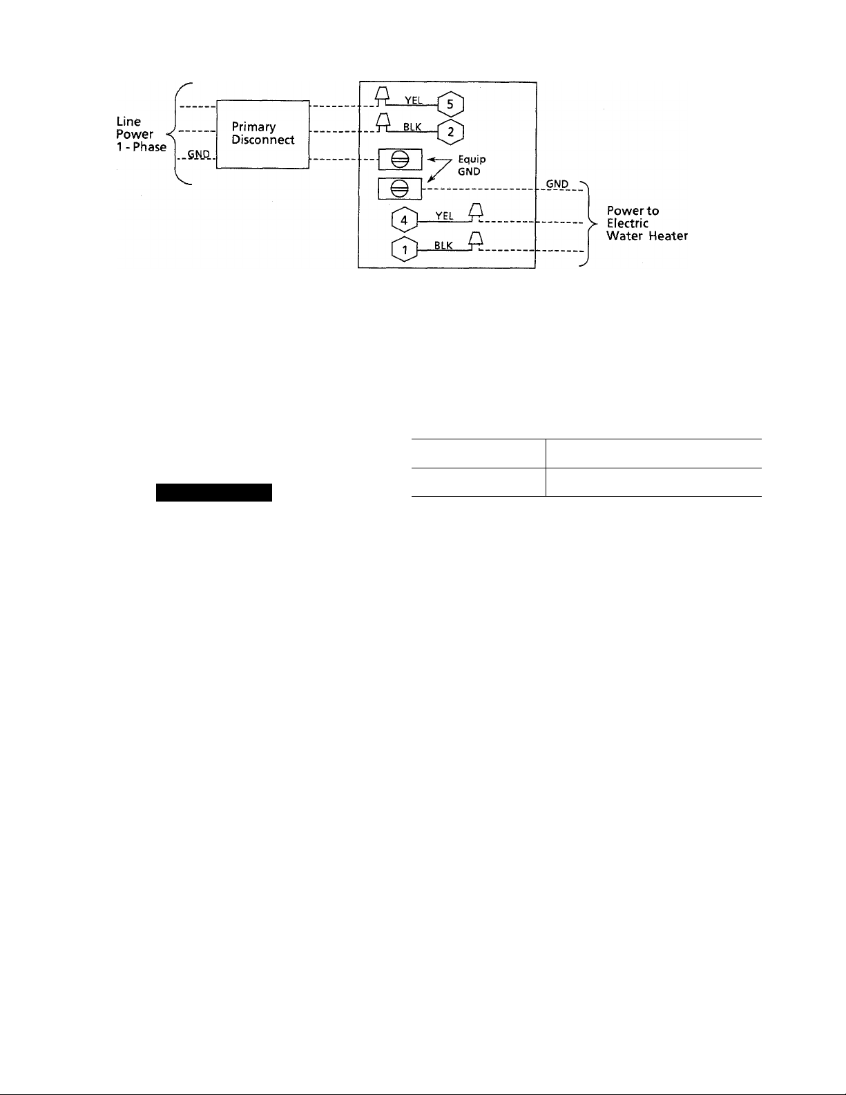
38QE Water Heater
Control Box
Splice Connection
Field Wiring
Factory Wiring
Fig. 13—Water Heater Control Box Power Connections
(Electric Water Heater Only)
A89056
water heater control box and the domestic water heater
splice box.
A CAUTION
The water heater control box is designed for a maxi
mum of 20 Amps. Make certain that the water heater
does not exceed this 20 Amp limit. This system is not
designed to be installed with commercial grade electric
water heaters that may have greater than 20 Amp
requirements.
Indoor Fan Coil Section
Install branch circuit disconnect of adequate size to handle
indoor fan coil section. The proper wire sizing and lengths,
circuit breaker or fuse amp requirements are included in the
40QE installation instructions. Indoor power connection
diagrams are also included in the 40QE installation
instructions.
SYSTEM SET-UP ADJUSTMENTS
Step 14—Inspect Indoor Blower Speed Limits
40QE fan coils are supplied with maximum and minimum
speeds preset at the factory. Maximum and minimum
blower speeds are determined by an 11-pin torque selection
connector located on the blower controller. (See indoor imit
installation instructions for component location.)
To Inspect Blower Speed Settings—
1. Remove indoor unit access doors.
2. Refer to indoor unit installation instructions to locate
11-pin speed selection connector on controller.
3. Check for proper factory speed pin settings on control
ler and adjust as shown below, if necessary.
Minimum and maximum settings may require adjustment
later. Refer to the 38QE and 40QE Start-Up and Service
Instructions.
Step 15—Adjust Domestic Water Heating Tank Thermo
stats (Electric Heater Only)
Adjust the lower element thermostat setting to the mini-
INDOOR
UNIT
40QE024
40QE036
Refer to 40QE Installation Instructions for proper Indoor Fan Coll Blower
setup.
NOMINAL SPEED SETTINGS
(MAX.-MIN.)
5-2
7-3
mum value possible. This maximizes the heat pump water
heating capability. If this element is set above 100 F the
heat pump will not provide water heating. When the tem
perature setting of the lower element is above 100 F the
tank will operate as a conventional electric water heater.
(NOTE: If the 38QE has been installed with a conventional
gas water heater the above steps are not required.)
Step 16—Configure Thermostats
In order for the 38QE system to work properly the thermo
stat must be corrrectly configured.
This procedure contains basic instructions for thermostat
operation. For detailed information on adjusting setpoints
or setup, refer to the instructions inside the thermostat
cover and the HydroTech 2000 Start-up and Service
Manual.
If the thermostat appears to malfunction during this proce
dure, refer to the appropriate Parker Thermostat Operation
Manual. HydroTech 2000 Start-up and Service Manual or
the Parker Homezone Troubleshooting Guide.
Make sure thermostat mode switches are set to OFF, and
FAN is set to AUTO.
Turn the indoor unit main disconnect switch ON (Note:
Transformers supplying power to multi-zone dampers and
thermostats may be on separate circuit from indoor unit.).
When the thermostat is powered up, the display will show
cooling and heating set points. If the display is blinking on
and off, it is indicating incorrect wiring connections or that
the thermostat is not receiving adequate power. Check wir
ing connections and supply voltage from the transformer.
The voltage must be 22 volts minimum. Make certain that
the thermostat ribbon cable has been inserted into the con
nector board correctly.
12
Page 13
If the thermostat displays a hardware, software, heat pump,
or fan coil error code (HF,SF,HP or FC followed by a two
digit number), refer to the HydroTech 2000 Start-up and
Service Manual for further instruction on how to isolate and
clear system problems.
At initial start-up, thermostat(s) and bypass controller func
tions must be manually configured. This may be accompHshed per the instructions located under the thermostat
cover with addressing exceptions as Hsted below:
NOTE: Be sure to correctly configure system for a variable
speed system and single- or multiple-zone application as
detailed in the instructions for rotary switch position F8, F9
and F13.
The proper configuration, programming and setup for
single- and multiple-zone installations are described here:
1. Address numbers 1 thru 2 are reserved for the 38QE
controls. No other devices can use address 1 thru 2. Be
sure the 38QE compressor section control module is set
to address 1 and the 40QE fan section control module
is set to address 2.
2. The monitor thermostat used for single-zone applica
tions should use address 3.
3. For multiple-zone apphcations the monitor thermostat
MUST BE addressed to the highest number followed
by the bypass controller (required) and then the slave
thermostats in any order (example: monitor thermostat
is address 6, bypass controller is address 5, zone 2
slave thermostat is address 4, zone 3 slave thermostat
is address 3.)
4. Power to indoor unit must be cycled after any change
to monitor thermostat address.
After all device features have been set or checked, return all
rotary switches to position 0 then, start-up and check the
operation of the 38QE variable speed system. Refer to
HydroTech 2000 Start-up and Service Manual.
To check the configm-ation:
1. Power up the thermostat.
2. Remove the thermostat cover.
3. Turn the rotary switch to the position indicated in
Table 5.
4. Check that the configuration settings are correct.
After the configuration values are correctly set:
1. Turn the rotary switch to position “0”.
2. Replace the thermostat cover.
These configuration items are the minimum required to get
the system running. There are many other options and fea
tures available through the remaining configuration set
tings. Refer to the Parker Reference Manuals for a complete
description and correct use of these additional features.
Step 17—Adjust Refrigerant Charge
38QE refrigerant charge adjustment or recharge must be
made by weighing-in the proper amount of refrigerant. Serv-
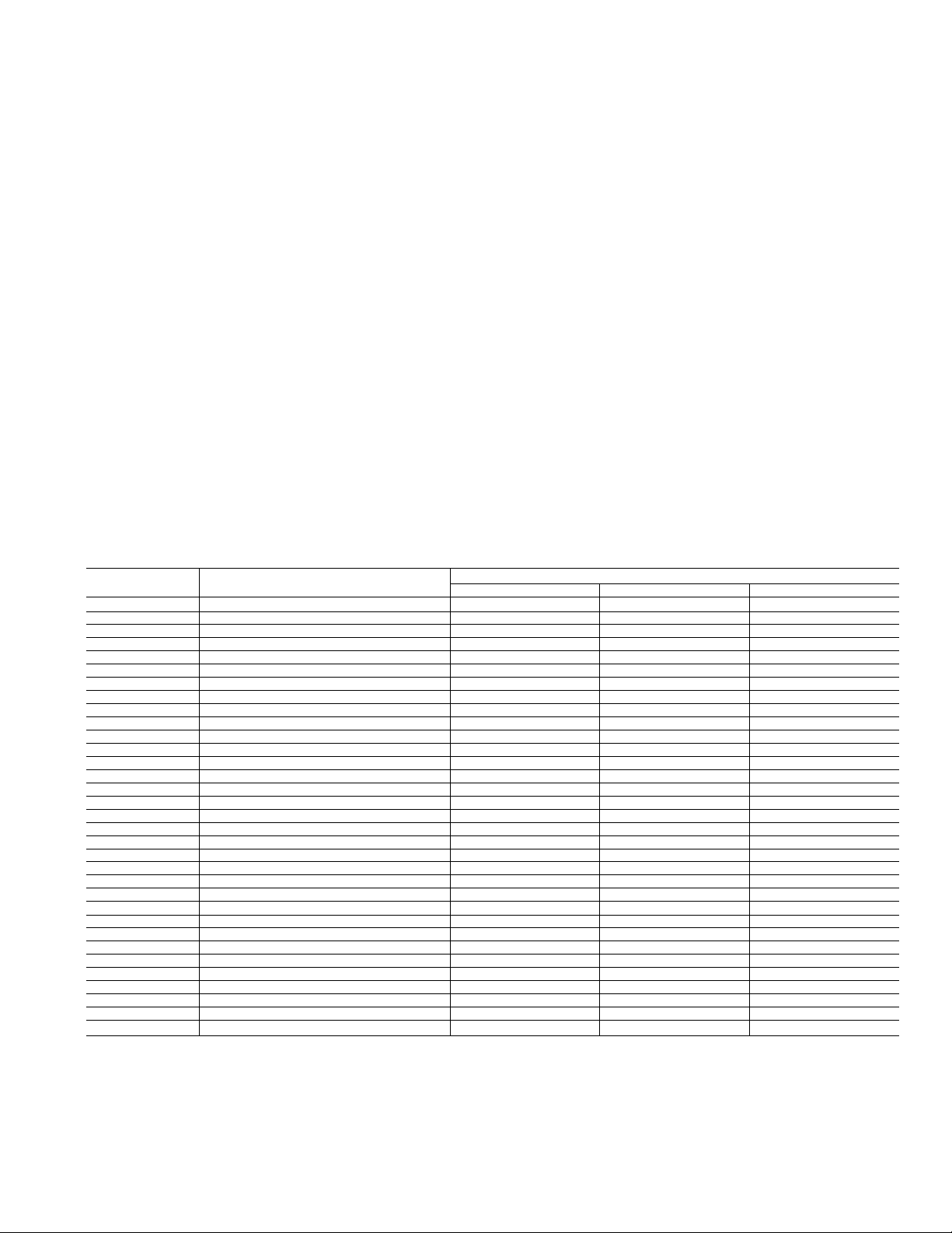
Table 5—Carrier/Parker HT2000 Home-Zone® Thermostat Configuration
ROTARY SWITCH
POSITION ROTARY SWITCH SETTING
0 COMFORT SETPOINTS 74 74 74 74
1
2 SETBACK OVERRIDE TIME LIMIT 60
3
4
4
5 ZONE TEMP. SENSOR CALIBRATION
6 SUPPLY AIR TEMP. SENSOR CALIBRATION
7 COMMUNICATION CHECK
8 PRESSURE SENSOR ERROR CORRECTION
9
A
B
c
D NOT USED
E
F1
F2
F3 ERROR CODE DISPLAY
F4 2400 BAUD RATE
F5
F6
F7
F8
F9
F10
F11
F12
F13
F14
F15
F16
FI 7
*VSE PARAMETERS ARE USED TO CONFIGURE OR TROUBLESHOOT THE VARIABLE SPEED SYSTEM. FOR DETAILS, REFER TO THE START-UP
AND SERVICE MANUAL FOR THE COMPRESSOR BEARING SYSTEM.
NOTE: ADDRESS THERMOSTAT FOR MULTIPLE-ZONE OPERATION AS FOLLOWS: SLAVE 2 ADDRESS = m-3
MONITOR ADDRESS = m I
BYPASS CONTROL ADDRESS = m-1 I
SLAVE 1 ADDRESS = m-2 SLAVE x ADDRESS = 3
DEVICE ADDRESS
SETBACK SETPOINTS 85 65 85 65
DAMPER MAXIMUM OPEN POSITION
DAMPER VENTILATION POSITION 05
MAXIMUM PRESSURE SETPOINT 100*
HUMIDITY SETPOINT 50
SYSTEM MODE DEMAND/LARGE DEMAND
VARIABLE SPEED EQUIPMENT CONFIG.
NOT USED
HTG./CLG. TIMEGUARD OVERRIDE
CELSIUS TEMPERATURE DISPLAY
HEAT PUMP SYSTEM ON
LOCAL OUTSIDE AIR TEMP. SENSOR**
DX COIL TEMPERATURE SENSOR OFF
MULTIPLE ZONE SYSTEM OFF
VARIABLE SPEED EQUIPMENT ON
LOCAL HUMIDITY SENSOR OFF
EFFICIENCY OPERATING MODE OFF*
ALTERNATE INFORMATION DISPLAY
HIGH/LOW TEMPERATURE LIMITS OFF
AUTO FAN OFF FOR HEAT
TEMPERATURE TREND STAGING ON
SETBACK LOCKOUT OFF
BYPASS CONTROLLER OFF
FACTORY SET. SINGLE ZONE
3
15
*
*
OFF
*
1
*
BLANK BLANK BLANK
BLANK
OFF
OFF
ON
ON
OFF
OFF
ON
X = NO. OFZONES-1
4 ZONES MAX. (MONITOR -I- SLAVES)
(REFER TO COMPRESSOR UNIT INSTRUCTIONS
FOR OTHER ZONING LIMITATIONS)
DISPLAY
3 m*
60
15
05 05
*
MULTIPLE-ZONE
*
OFF
*
100*
50
1 4
«
BLANK
OFF
OFF
ON
ON
ON
OFF
OFF
OFF
ON
OFF
OFF*
OFF
OFF
ON
OFF
OFF OFF
OFF
74 74
60
85 65
15
*
*
OFF
*
100*
50
1 4
*
BLANK
OFF
OFF
ON
ON
ON
OFF
OFF
ON
ON
OFF
OFF*
OFF
OFF
ON
OFF
ON
13
Page 14

ice ports are provided on the liquid and vapor service
valves. Schrader fittings are also provided on the suction
and discharge tubes within the compressor section. Dial-ACharge charging cylinder is an accurate device for recharg
ing systems by weight.
A WARNING
Outdoor section service valve gauge ports are not
equipped with schrader valves. To prevent personal
injury, make sure gauge manifold or port caps are con
nected to the valve gauge ports before moving valves
off fully backseated position. Wear safety glasses and
gloves when handling refrigerant.
A CAUTION
Evacuate and purge BOTH suction and discharge
Schraders of COMPRESSOR SECTION. Purging only
from one or from only the outdoor service valves may
result in refrigerant being isolated in indoor section due
to system refrigerant control valving.
A CAUTION
Compressor damage may occur if system is over
charged. Weigh-in all refrigerant.
Initial system charging
The outdoor units are shipped with the base system refrig
erant charge for correct operation with a total piping length
from indoor section to outdoor section of 25 ft. The remain
ing components of the system should be leak-checkefl and
evacuated or purged before opening the service valves at
the outdoor cod. The procedure described here should be fol
lowed for the initial charge:
1. Pressurize the remaining system with R-22 vapor to
100 psig.
A WARNING
Never use oxygen or other flammable gases in a refrig
eration system for leak checking or any other purpose.
Personal injury or death can result from doing so.
After refrigeration system has been pressurized, with
the appropriate gas, to 100 psig, inspect all compo
nents, solder joints, mechanical connections, etc., for
leakage.
3. If a leak is found, do not attempt to repair until all
pressure has been reheved from the system. After the
pressure has been reheved, make repairs to leaking
component, repressurize system to 100 psig and con
tinue leak checking.
4. After ah components, solder joints, mechaniceJ connec
tions, etc. have been leak-checked, reheve ah system
pressure and evacuate or purge system.
NOTE: If either refrigerant tubing or unit piping is exposed
to atmospheric conditions for longer than 5 minutes, it must
be evacuated to 1000 microns to eliminate contamination
and moisture in the system.
5. Slowly open (turn clockwise) both service valves on the
outdoor fan coil section allowing the bare system
refrigerant cheuge to be released throughout the sys
tem. Service valves should be fuhy opened and back
seated. Port caps mstahed tightly.
6. Unit is shipped with valve stem(s) frontseated, and
caps installed. Replace stem caps after system is
opened to refrigerant flow (backseated). Replace caps
finger tight and tighten additional 1/12 turn (20-ft lbs
torque) using a backup wrench on valve body flats to
prevent distortion of sheet metal.
7. See refrigerant charging instructions or charging label
of outdoor or compressor section for field charge
adjustment for piping lengths used.
Full charge replacement
If refrigerant escapes from the system, leak test and evacu
ate entire system. Fohow precautions hsted in initial system
charging. Weigh-in system base charge plus adjustment for
field piping. Refer to charging label on outdoor or compres
sor section.
System Startup
A WARNING
DO NOT attempt to manually operate the contactor for
any reason. PersoneJ injury can result.
NOTE: The 38QE system compressor section is equipped
with a crankcase heater. It is recommended that the heater
be energized 24 hours prior to starting the unit. To energize
crankcase heater set thermostat mode swritches to “off,”
turn on power to compressor section to the indoor fan coU
and thermostat.
Refer to the HydroTech 2000 Start-up and Service Manual
for further instructions before operating system. Leave the
thermostat mode switches to ‘OFF’ position until the start
up instructions have bjgen>thoroughly and completely read
and proper system op®E&on has been confirmed.
Copyright 1990 Carrier Corporation
Manufacturer reserves the right to discontinue, or change at any time, specifications or designs without notice and without incurring obligations.
I
Tab l5al5a
^ PC 101 Catalog No. 563-964 Printed in U.S.A. Form 38QE-3SI Pg 14 , 5-90 Repiaces: 38QE-2Si
 Loading...