

Page 1
Number One
AirConditbninq
Maker
Installation, Start-Up
Division of
Carrier Corporation
e
Carrier Parkway • Syracuse NY 13221
and Service Instructions
Heat Pump — Outdoor Section
CONTENTS
SAFETY CONSIDERATIONS............................. 1
INSTALLATION
Step 1 —Check Equipmentand Jobsite.. 1
• UNPACK UNIT
• INSPECT EQUIPMENT
• COMPLETE OR CONSIDER SYSTEM
REQUIREMENTS
Step 2 — Mount Outdoor Heat Pump ... 2
• ON THE GROUND: MOUNT ON A
SOLID, LEVEL CONCRETE PAD
• ON THE ROOF: MOUNT ON A LEVEL
PLATFORM OR FRAME
Step 3 — Make Piping Connections
• REPLACE THE ACCURATER™ RE
FRIGERANT CONTROL PISTON IN
THE INDOOR COIL AS REQUIRED
• CONNECT REFRIGERANT LINES
Step 4 — Make Electrical Connections... 5-6
• INSTALL A BRANCH CIRCUIT
DISCONNECT PER NEC
• ROUTE LINE POWER LEADS
INTO UNIT
• CONNECT GROUND LEAD AND
POWER WIRING
• SEE INDOOR UNIT AND ELECTRIC
HEATER INSTALLATION, START-UP
AND SERVICE INSTRUCTIONS
• CONNECT CONTROL POWER
WIRING (24 v)
START-UP..........................................................6-8
SERVICE
MAINTENANCE
Installation and servicing of air conditioning
equipment can be hazardous due to system pres
sure and electrical components. Only trained and
qualified service personnel should install, repair or
service air conditioning equipment.
Untrained personnel can perform basic mainte
nance functions of cleaning coils and cleaning and
replacing filters. All other operations should be per
formed by trained service personnel. When working
on air conditioning equipment, observe precautions
in the literature, tags and labels attached to the unit
and other safety precautions that may apply.
..........................................................
.................................................
....................
.............................................
SAFETY CONSIDERATIONS
8-16'*
16-19
Page
1-6
2-5
Follow all safety codes. Wear safety glasses and
work gloves. Use quenching cloth for brazing opera
tions. Have fire extinguisher available for all brazing
operations.
INSTALLATION
Step 1 — Check Equipment and Jobsite
UNPACK UNIT — Move to final location. Lift
carton off, taking special care not to damage service
valves or grilles.
INSPECT EQUIPMENT — File claim with ship
ping company if shipment is damaged or incomplete.
COMPLETE OR CONSIDER SYSTEM RE
QUIREMENTS before installing the 38QB.
Consult local building codes and National Elec
trical Code (NEC) for special installation
requirements.
When installing, allow sufficient space for airflow
clearance, wiring, refrigerant piping and servicing.
Position so water or ice from roof cannot drop
directly on top of unit.
Make provisions for condensate drainage and
defrost water disposal whether unit is installed on
ground or roof. (Ensure unit basepan drainage holes
are not blocked.) See Step 2 for details. Roof instal
lation method for 38QB depends on building con
struction and special requirements of local codes.
Be sure that roof can support unit weight.
It is recommended that 38 QB units be used with
Carrier approved indoor sections; see Table I.
System Refrigerant Control on 38QB units and
matching Carrier indoor units is a factory-installed
AccuRater device (bypass-type). Bypass-type AccuRater components are discussed in the service sec
tion of this booklet. The AccuRater piston has a
refrigerant metering hole thru it and is field replace
able. Table 1 indicates indoor units for which the
required replacement piston is factory supplied with
specified 38QB outdoor unit. Replace piston as
described under AccuRater Servicing on page 15.
© Carrier Corporation 1983 Form 38QB-7SIM
Page 2
^ Table 1 — Carrier Approve^^6^ Systems
OUTDOOR
UNIT
38QB
015
018
024
030
036
042
048
060
‘Replace factory-installed piston with this piston size
REQUIRED
OUTDOOR
PISTON
SIZE
38
42
46
59
61
63
73
82
INDOOR
UNIT
MODEL 8i
SIZE
28HQ.VQ018
40AQ018
40DQ018
28HQ.VQ024
40AQ024
40DQ024
28HQ.VQ024 55
40AQ024
40DQ024 59
28HQ.VQ030
40AQ030
40DQ030
28HQ.VQ030
40AQ030
40DQ030
28HQ.VQ036
40AQ036
40FS160 1 28HQ.VQ036
28HQ.VQ036
40AQ036
40FS160 1 28HQ.VQ036
28HQ.VQ042
40FS160 1 28HQ.VQ042
40QB.QH042
28HQ.VQ042
40FS160 I 28HQ,VQ042
40QB.QH042
28HQ.VQ048
40FS200 1 28HQ.VQ048
40QB.QH048
40QB.QH060
REQUIRED
INDOOR
PISTON
SIZE
46
46*
52*
55*
61*
63
63*
63
70*
67
76
76
86*
93
4'-0" (1220 mm) OVERHEAD SPACE REQUIRED
FOR SERVICE AND AIRFLOW
TOP
COVER
DIAM HOLE
FOR POWER
WIRING
LIQUID VALVE SERVICE PORT f VAPOR VALVE SERVICE PORT
[//> AIRFLOW SUCTION SERVICE PORT
I
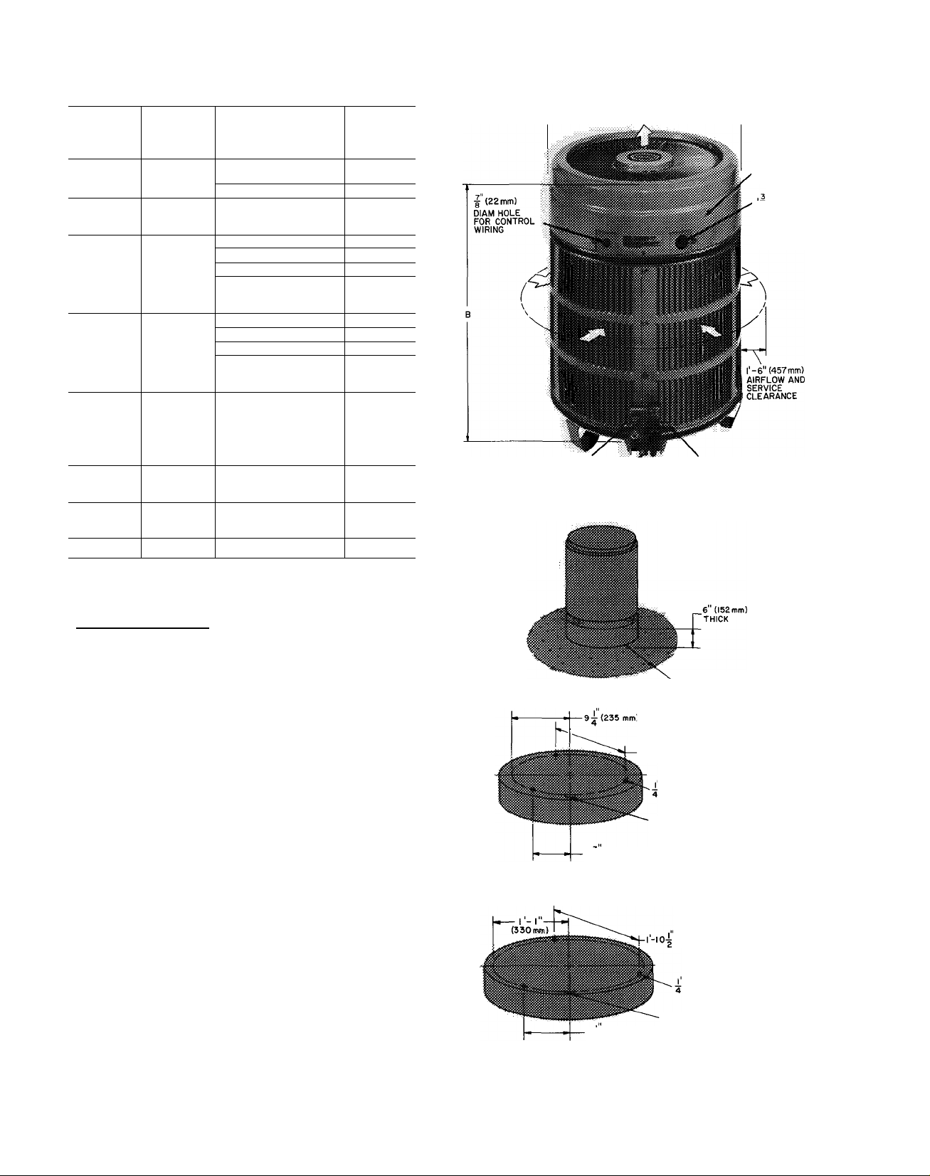
Top Cover Removal — Top cover can be removed
for wiring or servicing heat pump. Loosen decora
tive strip and slide down off screw heads. Remove
3 screws in connector plate and 2 screws on front of
unit. Loosen remaining 4 serews. Lift top from unit
(see Fig. 1).
Step 2 — Mount Outdoor Heat Pump
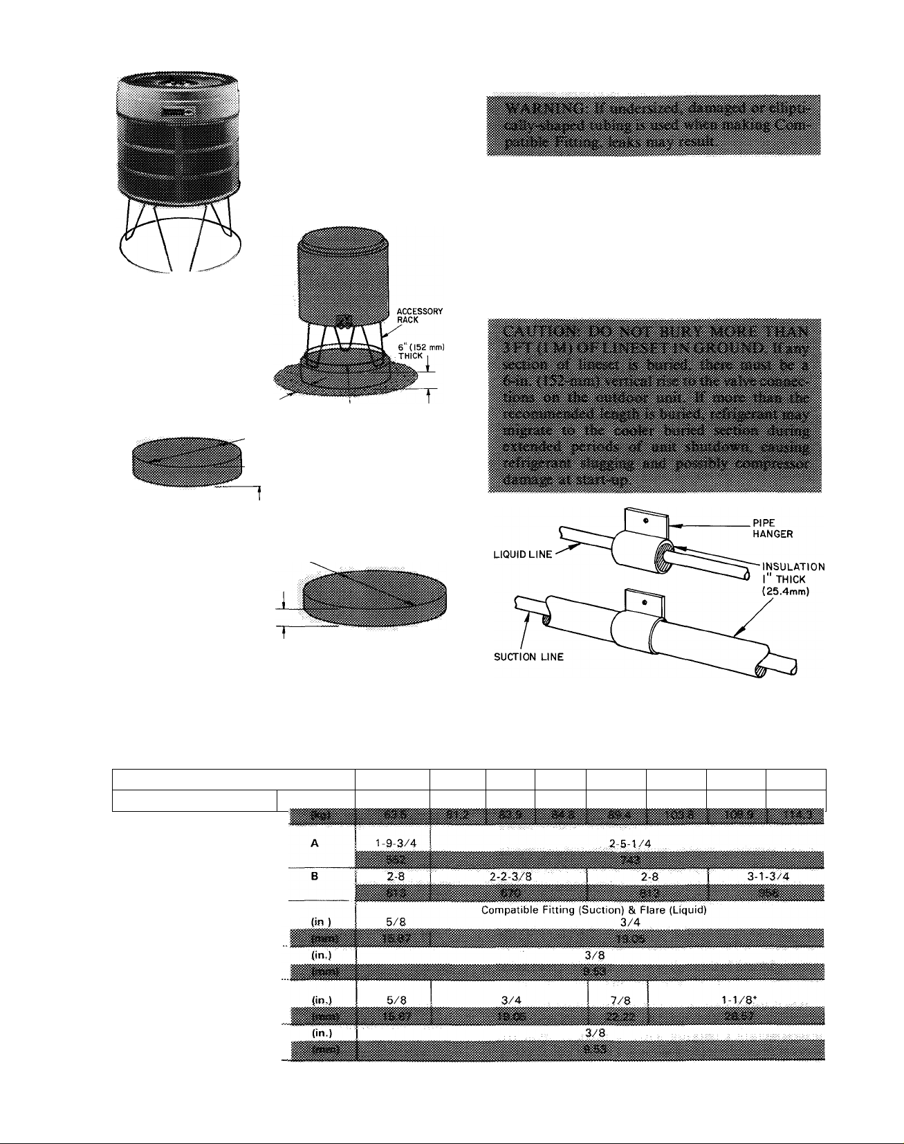
ON THE GROUND: MOUNT ON A SOLID
LEVEL CONCRETE PAD (see Fig. 1). Swing 3
legs down and lock in position, except when using
accessory rack. Use accessory heat pump rack
(Fig. 2) in areas where prolonged subfreezing tem
peratures or heavy snow occur. (Refer to installation
instructions included with rack.) Drainage holes in
unit base must not be obstructed.
ON THE ROOF; MOUNT ON A LEVEL PLAT
FORM OR FRAME. Proper precaution must be
taken for support of unit in roof design. Elevate unit
for proper clearance as described under ground
installation, above. Plan roof design and water
drainage to prevent unit from setting in water. Flash
all roof openings to prevent leaks.
Roof mounted units exposed to winds above
5 mph (8 km/h) may require protective wind baffles
(field fabricated) to achieve adequate defrost.
12 (305mm)
GRAVEL APRON
I-4 (407mm) TYPICAL 3 PLACES
(6.35 mm) TIEDOWN BOLTS
CENTERLINE BETWEEN
VALVES
6^ (172 mm)
Г-н" (585mm) DIAM x 6"(l52mm)THK CONCRETE
MOUNTING PAD FOR 38QB0I5
(572 mm) TYPICAL 3 PLACES
(6.35 mm) TIEDOWN BOLTS
CENTERLINE BETWEEN
9^ (241 mm)
VALVES
Step 3 — Make Piping Connections — Heat
pumps may be eonneeted to indoor sections using
Carrier aecessory tubing package (Table 3) or fieldsupplied tubing of refrigerant grade, correct size and
2-6" (762 mm) DIAM x 6" (152mm) THK CONCRETE
MOUNTING PAD FOR 38QB0i8-060
Fig. 1 — Dimensions, Connections and
Mounting Pad (Refer to Table 2.)
Page 3
condition (Table 2). For requirements beyond 50 ft,
obtain information from loeal Carrier distributor.
If 1-1/8in. tubing is used (38QB042,048,060),
braze it to the accessory 1-1/8 x 3/4-in. suction
connection adapter (Carrier Part No. 28AU900061)
or to a correctly sized field-supplied adapter, then
make Compatible Fitting connections. Isolate inter
connecting tubing from framing and ductwork or
where tubing runs thru stud spaces, enelosed ceilings
or pipe chases. Use isolation type hangers. Fig. 3,
since rigid fastening transmits pulsations to struc
ture creating objectionable sound.
I'-O" (305 mm)
GRAVEL APRON
Г-И" (584mm) DIAM
б" (152 mm)
THICK
CONCRETE MOUNTING PAD FOR 38QB0I5
2-6" (762mm) DIAM
6" (152 mm)
THICK
CONCRETE MOUNTING PAD FOR 38QB0I8-060
Fig. 2
- Accessory Mounting Rack
‘marker tape
(HIDDEN)
Table 2 — Installation Data (Fig. 1)
UNIT 38QB 015
OPERATING WEIGHT
(l|))
140 179
018
Fig. 3 — Refrigerant Line Hangers
024 030
185 187 , 197
036
042
229
048
240
060
252
DIMENSIONS
Diameter (ft-in.)
(mm)
Height (ft-in.)
(mm)
REFRIGERANT CONNECTIONS
Suction (ODF)
Liquid (ODF)
REFRIGERANT LINES
Suction (ODF)
Liquid (ODF)
‘May use 7/8-in (22 22-mm) accessory tubing package with slight capacity loss See Table 3
3
Page 4
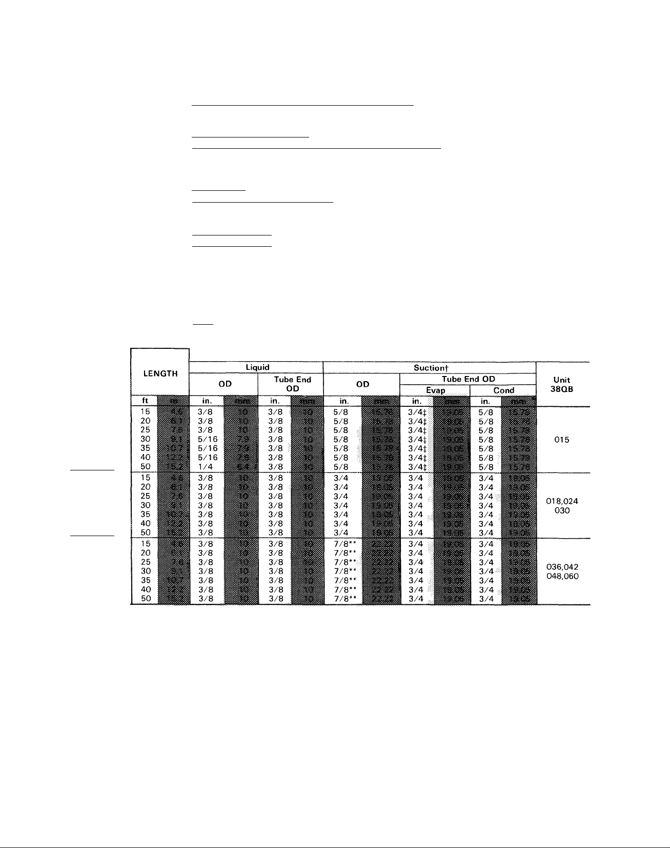
Table 3 — Accessories
PART NO.
99TZ90040106
99TZ90041106
38QB90002106
99TZ90029101
28AU90006112
38R090008106
HN65DE026*
38HQ900002
38CQ900172
38RQ900091
38QB90001106
38QF90000106
38HQ90014106
38QB90003106
HC95DD120* Start Capacitor
HC95DD12V Start Capacitor
HC95DD058* Start Capacitor
HC95DD088* Start Capacitor
HN61HB515* Relay
HN61HB496*
38EB660002*
TUBING
PACKAGE
Low-Voltage Control — Honeywell Thermostat HH07AT171 and
Thermostat Subbase HH93AZ173 — (Automatic Changeover)
Low-Voltage Control — Honeywell Thermostat HH07AT171 and
Thermostat Subbase HH93AZ175 — (Manual Changeover)
Service Sentry (Six HN65CT004)
Honeywell — Manual Changeover. 2-Stage Heating, 1-Stage Cooling
Twelve 3/4- x 1-1/8 in. Connection Adapters
Bi-Flow Heat Pump Filter Drier (Six KH45LD077)
Supplemental Heat Relay-
(Service Parts)
Outdoor Thermostat (Six 38HQ900011)
0ptimizerControlOutdoorThermostat(Six38CO900161 ref HH22AG110)
Optimizer II Control Assembly (Use with HH2AG1 lOoutdoorthermostat.)
Heat Pump Rack (Six)
Heat Pump Rack (Six)
Optimizer III (Six 38HQ900141)
Solid-State Time Guard II (24-volt)
Relay
Wire Bundle for Start Capacitor and Relay
__________
DESCRIPTION
- (Required with 2 Outdoor Thermostats )
TUBING
UNIT 38QB
All
042-060
All
015-018
024-060
All
015
018
024,030
036
015,018
024,030,036
015-036
38LS958151
38LS958201
38LS958251
38LS958301
38LS958351
38LS958401
38LS958501
38LS934151
38LS934201
38LS934251
38LS934301
38LS934351
38LS934401
38LS934501
38LS978151
38LS978201
38LS978251
38LS978301
38LS978351
38LS978401
38LS978501
*Available thru Carrier Service Parts
tSuction line is insulated and has 90° bend
tFor 5/8-in (15 9-mm) evaporator connection, cut off 3/4-in (19 05-mm) belled end
‘‘Capacity reduction may occur when 7/8-in (22 22-mm) accessory tubing is used on 38QB042,048,060
A capacity reduction will result if accessory tub
ing is used in 38QB042 systems. For example, when
a 25-ft (7.6-m) 7/8-in. (22-mm) accessory package is
used, there is a capacity reduction of 1-1/2percent.
When other than 25 ft (7.6 m) of interconnecting
tubing is used, follow special requirements described
in Refrigerant Charging. Do not use less than 10 ft
(3 m) of interconnecting tubing. Do not cut 5/ 16-in.
(7.9-mm) or 1/4-in. (6.4-mm) liquid line due to
swage at ends. Do not cut 7/8-in. (22.22-mm)
suction line. Bend or coil to fit.
Do not use damaged or contaminated tubing.
Always evacuate or purge evaporator coil and
tubing system (use field-supplied refrigerant, not
unit refrigerant).
When making tubing connections, be sure to
provide clearance at unit for electrical connections.
Page 5
REPLACE THE ACCURATER™ REFRIGER
ANT CONTROL PISTON IN THE INDOOR
COIL AS REQUIRED before connecting refriger
ant lines. See Table I. Correct piston is supplied
with 38QB unit. For piston replacement instruc
tions, see AccuRater Servicing on page 15.
CONNECT REFRIGERANT LINES to fittings on
unit suction and liquid service valves (Fig. 1).
Liquid service valve has flare fitting; suction service
valve has Compatible Fitting. Make suction line
connection first. Slide flare nut on liquid line, then
flare and connect liquid line. Use a maximum
torque of 15ft-lb (20N-m) to tighten flare nut. (Do
not disassemble AccuRater.) Unit Compatible
Fitting permits mechanical or sweat connection as
described below.
When a 7/8-in. (22.22-mm) field-supplied suction
line is used on 38QB036,042,048 and 060, a field-
supplied 3/4-in. (19.05-mm) to 7/8-in. (22.22-mm)
suction line adapter must be provided (not required
if 38LS accessory tubing is used).
When a 1-1/8in. (28.57-mm) field-supplied
suction line is used on 38QB042,048 and 060, use
accessory adapter 28AU900061 or other fieldsupplied connection. Sweat connect refrigerant
suction line to 1-1/8 in. (28.57-mm) end of adapter.
Connect 3/4-in. (19.05-mm) end of adapter to unit
suction line Compatible Fitting.
Mechanical Connection to Compatible Fitting
(Mate one set of connections at a time.)
1. Loosen nut on Compatible Fitting one turn. Do
not remove.
2. Remove plug and be sure O-ring is in the groove
inside the Compatible Fitting.
3. Cut tubing to correct length.
4. Insert tube into Compatible Fitting until it
bottoms.
5. Tighten nut until it bottoms on back coupler
flange. Keep tube bottomed in Compatible
Fitting while tightening nut.
Sweat Connection to Compatible Fitting (Use
refrigerant grade tubing.)
1. Remove locking nut, rubber O-ring and Schrader
core from valve.
2. Cut tubing to correct length.
3. Insert tube into Compatible Fitting. Wrap top
and bottom of service valves in wet cloth to pre
vent damage by heat. Solder with low tempera
ture (430 F [221 C]) silver alloy solder.
4. Replace Schrader core.
5. Evacuate or purge system with field-supplied
refrigerant.
nameplate. Contact local power company for cor
rection of improper line voltage.
Do not apply units in system where voltage may
fluctuate above or below permissible limits.
When making electrical connections, provide
clearance at unit for refrigerant piping connections.
See Table 4 for recommended wire and fuse sizes.
INSTALL A BRANCH CIRCUIT DISCONNECT
PER NEC of adequate size to handle unit starting
current. Provide a separate disconnect for outdoor
unit, indoor unit and for each accessory electric
heater circuit as required. (See Indoor Unit and
Electric Heater Installation, Start-Up and Service
Instructions.) Locate disconnect(s) within sight
from and readily accessible from the unit per section
440-14 of National Electrical Code (NEC).
ROUTE LINE POWER LEADS INTO UNIT —
Extend leads from disconnect thru power wiring
hole provided (see Fig. 1) and into unit splice area.
Remove top cover to gain access to unit wiring.
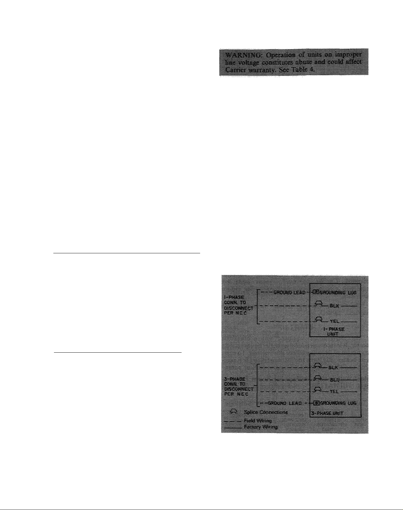
CONNECT GROUND LEAD AND POWER
WIRING — Connect ground lead to a ground lug
in control box for safety. Then connect power
wiring. See Fig. 4. Splice line power leads to yellow
and black pigtails. Use wire nuts and tape at each
connection. Connect unit wiring to copper power
wiring.
Fig. 4 — Line Power Connections
Step 4 — Make Electrical Connections — Field
wiring must comply with local and national fire,
safety and electrical codes. Voltage to unit must be
within permissible limits of voltages indicated on
SEE INDOOR UNIT AND ELECTRIC HEATER
INSTALLATION, START-UP AND SERVICE
INSTRUCTIONS for line power wiring details. All
control wiring is shown in this booklet.
Page 6
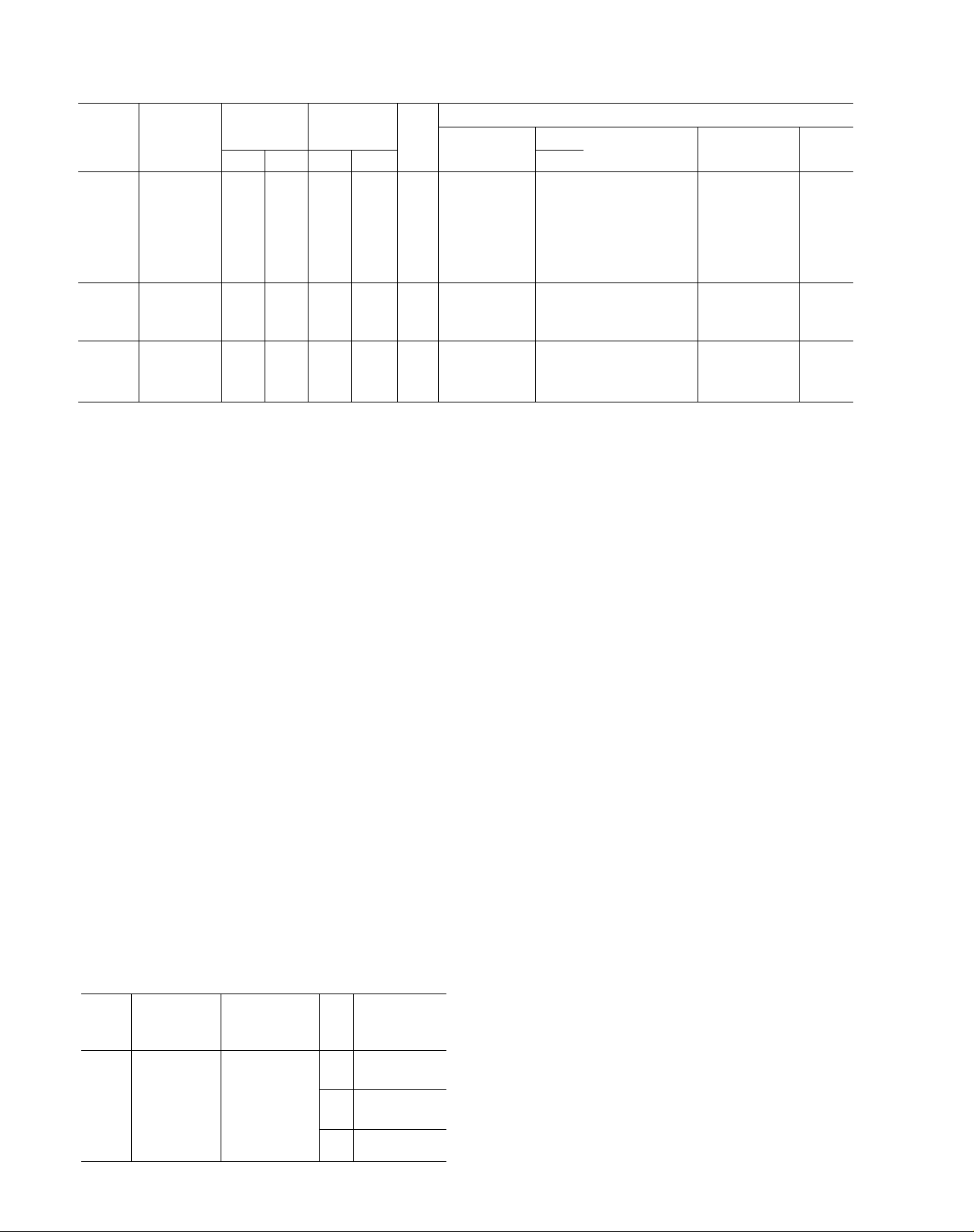
Table 4 — Electrical Data (60 Hz)
UNIT
38QB
015
018
024 208-230/1
030
036
042
048
060
036
042
048
060
036
042
048
060
AWG — American Wire Gage
FLA — Full Load Amps
FIACR — Heating, Air Conditioning and Refrigeration
LRA — Locked Rotor Amps
MCA — Minimum Circuit Amps
RLA — Rated Load Amps
‘Permissible limits of the voltage range at which the unit will
operate satisfactorily
V/PH
208-230/1 254
208-230/1 254
208-230/1 254
208-230/1 254
230/1 254 207
230/1 254 207 105
230/1 254 207
208-230/3
208-230/3 254 197 80 13 3 24 14 29 1
208-230/3
208-230/3
460/3
460/3 506
460/3 506
460/3 506
OPER
VOLTAGE*
Min
Max
197
197 48 124
254 197
197
197 88 20 6
254 197
254 197 80 16 3 24 12
254 197 98
506 414 30 5 1 1 2 14 159 1
414 35 72 1 2 14 120 1
414 40
414 49 104 1 2
COMPR
LRA
RLA
34
66
15 5 24 12 32 ;l 12
82
165
98
199 24
22 4
130 27 8
87
11 7 24 14 32 1
20 9 24
7 7
80
FAN
FLA
1 25
1 25
24
24
24
24
1 2 14 109 1
Min Wire
Size (AWG)t
14
14
12 32 1 12
10
10
8
8
10
14
tCopper wire sizes based on 60C Use copper wire only.
tRequired when using nonmetallic conduit
“Time-delay fuse
NOTE: All units have 24-v control circuit which requires external
power source
Max \
40 1
27 1
39 1
44 1
62 1
51 I
24 1
_3I ■
BRANCH CIRCUIT
'Vire ; 1 Min Gnd
Wire Sizel
M 10
__________
14
u
10
10
10
14
14
12
14
14
14
______
Max Fuse**
or HACR Type
Ckt Bkr Amps
15 109
25
35
35 23 0
45
45
50
60
25
30
35
45
15
15
15
20
MCA
168
21 8
28 2
27 3
30 4
37 2
170
190
22 8
28 5
76
102
11 2
142
CONNECT CONTROL POWER WIRING (24 V)
— Extend wiring thru hole provided (Fig. I) and
into low-voltage section of unit control ring.
Connect leads to control wiring terminal board as
shown in Fig. 5.
Use indoor unit transformer as 24-v supply for
system. At least a 60-va transformer is recom
mended. Carrier approved indoor units are
equipped with a 60-va transformer. See indoor
unit data.
Use Carrier accessory indoor thermostat with
suhbase, Table 3.
START-UP
The 38QB unit is equipped with a crankcase
heater. It is recommended that heater be energized a
minimum of 24 hours before starting unit. To ener
gize heater only, turn the thermostat to OFF posi
tion and close electrical disconnect to heat pump.
Heat Anticipator Settings for Room Thermo
stat (HH0IAT171) — Set anticipator for room
^ Table 5 — Thermostat Anticipator Settings
UNIT
38QB
015
018
024
030
036
042
048
060
FIRSTSTAGE
ANTICIPATOR
SETTING
Fixed
INDOOR
UNIT WITH
ELECTRIC
HEATER
40DQ and
40AQ Fan Coil
with 40AQ Htrs
or 40QB,QH
Fan Coil with
40QB Htrs
HTR
KW
150
20 0
25 0
30 0
34 0
ANTICIPATOR
50
7 5
100
SECOND-
STAGE
SETTINGS
25
50
75
thermostat according to Table 5. These settings may
be changed slightly to provide a greater degree of
comfort for a particular installation.
Accessory Outdoor Thermostat provides adjust
able outdoor control of accessory electric heater.
This thermostat makes contact when a drop in out
door temperature occurs. It energizes a stage of elec
tric heat when the outdoor temperature setting is
reached, provided the room thermostat is on the
second stage of heating. One outdoor thermostat is
recommended for each stage of electric heat after the
first stage. Set the outdoor thermostat(s) pro
gressively lower for each stage. Refer to heat load of
building and unit capacity to determine the correct
outdoor thermostat settings.
The accessory supplemental heat relay is required
when 2 outdoor thermostats are used. It is auto
matically energized by the manually operated
supplemental heat switch in the indoor thermo
stat subbase. The thermostat locks out compressor
and the relay bypasses the outdoor thermostats for
electric heater operation during heat pump shut
down. When one outdoor thermostat is used, a sup
plemental heat relay is not required. The supple
mental heat switch in the indoor thermostat subbase
bypasses outdoor thermostat, locks out compressor
and activates electric heater.
MOUNT OUTDOOR THERMOSTAT on control
ring, to the left of the low-voltage control connec
tion. See Fig. 1.
Attach brackets with short sheet metal screws to
avoid contaet with coil. Leave capillary tube coiled
in control compartment making sure it is clear of all
electrical connections and sharp metal edges.
Page 7

THERMOSTAT
AND
SUBBASE
40AQ OR 40QB FAN COIL
COOLING CONTROL KIT
TERMINAL BOARD
(38QB/40AQ 0R40QB WITHOUT ELECTRIC HEATER)
380B
TERMINAL
BOARD
THERMOSTAT
AND
SUBBASE
(38QB WITH 40AQ, 40QB,QH OR 40FS/28HQ,VQ
EQUIPPED WITH ELECTRIC HEATER;
SUPPLEMENTAL HEAT, ONE OUTDOOR THERMOSTAT)
40AQ OR 40QB
ELECTRIC HEATER
TERMINAL BOARD
COOLING AND TWO-STAGE HEATING
38QB
TERMINAL
BOARD
THERMOSTAT
AND
SUBBASE
COOLING AND TWO-STAGE HEATING
(38QB WITH 40AQ,40QB,QH OR 40FS/28HQ,VQ
EQUIPPED WITH ELE6tRIC HEATER;
SUPPLEMENTAL HEAT, NO OUTDOOR THEf^MOSTATS)
40AQ OR 40QB
ELECTRIC HEATER
TERMINAL BOARD
В
THERMOSTAT HH07AT171 40DQ ELEC.HEATER
WITH HH93AZI73(AUTO (ALL MODELS) 38QB
CHANGEOVER) OR HH93AZI75 LOW VOLTAGE TERM. TERMINAL
(MAM CHANGEOVER) SUBBASE SPLICE CONNECTIONS BOARD
38Q8
TERMINAL
BOARD
THERMOSTAT
AND
SUBBASE
COOLING AND TWO-STAGE HEATING
EQUIPPED WITH ELECTRIC HEATER;
SUPPLEMENTAL HEAT, TWO OUTDOOR THERMOSTATS)
40AQ OR 40QB
ELECTRIC HEATER
TERMINAL BOARD
(38QB WITH 40FS/28HQ,VQ
38QB
TERMINAL
BOARD
ODT — Outdoor Thermostat
SHR — Supplemental Heat Relay
------------
------------
Factory Wiring
Field Wiring
SUPPLEMENTAL HEAT, NO OUTDOOR THERMOSTATS)
‘Transformer (60 va) located in cooling control kit or electric heater
fRemove factory-installed jumper (Connection B) when installing outdoor thermostats (ODT)
Fig. 5 — Control Circuit Connections
Page 8

MOUNT SUPPLEMENTAL HEAT RELAY in
convenient location on indoor unit. Attach with
sheet metal screw.
To Start Unit — (Make sure crankcase heater has
been energized for 24 hours.) Adjust the thermostat
as follows:
1. Set selector switch at OFF.
2. Turn on main disconnect switch(es) to indoor
and outdoor units.
3. Set fan switch as desired (ON or AUTO.).
4. Set thermostat dial at desired temperature.
5. Set selector switch at HEAT or COOL.
Check system refrigerant charge. See Refrigerant
Charging.
(Fig. 8, 10, 12, 14, 16, 18, 20, 22) and follow
Charging Chart Method below. The charging chart
may also be used as an alternate method of recharg
ing system.
To check system operation during heating cycle,
use correct Heating Cycle Operation Check Chart
(Fig. 9, 11, 13, 15, 17, 19,21,23). These charts indi
cate whether a correct relationship exists between
system operating pressures and air temperatures
entering indoor and outdoor units. If pressure and
temperature lines do not intersect on chart, the sys
tem refrigerant charge may not be correct or other
system abnormalities may exist. Do not use Opera
tion Check Charts to adjust refrigerant charge.
Weigh charge into system.
SERVICE
Refrigerant Charging — The 38QB units contain
correct operating charge for complete system when
connected to 28HQ,VQ, 40QB,QH or 40AQ indoor
units with 25 ft (7.6 m) of tubing of recommended
diameter. Charge adjustment is required on other
systems. Adjust system charge for refrigerant line
lengths and diameters that differ from 25 ft (7.6 m)
and 3/8in. (10mm) OD (liquid line), respectively,
using refrigerant weights below. Twenty-five ft
(7.5-m), 3/8-in. (lO-mm)ODtubingcontains 14.4 oz
(.4 kg) of R-22. Add R-22 charge to system if liquid
line is over 25 ft (7.6 m); remove charge if liquid
line is shorter than 25 ft (7.6 m).
When recharging is necessary during heating or
cooling season, weigh in total charge indicated in
Table 6. (Charge must be weighed in during heating
season.) Remove any refrigerant remaining in sys
tem before recharging. If system has lost complete
charge, triple-evacuate system to 5000 microns
(29.7 in. [100.5 kPa] vacuum) before recharging.
Service port connections are provided on liquid and
suction line service valves for evacuation and charg
ing. (See Fig. 6 for correct service port location
on cooling and heating cycles.) Dial-a-charge
charging cylinder is an accurate device used to re
charge systems by weight. These cylinders are avail
able at refrigeration supply firms.
To check and/or adjust charging during cooling
season, use correct Cooling Cycle Charging Chart
LIQUID LINE
DIAM (in.)
3/8 .58
5/16 36
1/4 .21
Fig. 6 — 38QB Refrigerant Flow Diagrams
OUNCES OF R-22/FT LENGTH
OF LIQUID LINE
Page 9

Table 6 — Service Data
UNIT 38QB 015
R-22CHG (lb)
40
018 024
6 2
AccuRator-'-' (Bypass iypo)
030 036 042
7 3 7 8 8 5
7 2
048;
8 6
060
8 0
COOLING CYCLE CHARGING CHART
METHOD
1. Operate unit a minimum of 10 minutes be
fore checking charge, and after each charge
adjustment.
2. Measure suction pressure by attaching a gage to
outdoor unit suction service port. (See Fig. 6
for correct service port location on cooling cycle.)
3. Measure outdoor (coil inlet) air dry-bulb tem
perature with service thermometer.
4. Using a sling psychrometer, measure wet-bulb
temperature of air entering indoor unit.
5. Refer to correct Charging Chart. Locate on
curves where outdoor air dry-bulb and indoor
air wet-bulb temperature lines intersect.
6. From intersect point, project vertically down
ward to chart suction pressure line. Compare
chart suction pressure to unit suction pressure
(Step 2).
7. If unit suction pressure is lower than chart pres
sure, add refrigerant to system until chart
pressure is reached. If unit suction pressure is
higher than chart pressure, remove refrigerant
until chart pressure is reached.
Unit Single-Phase Compressors
COMPRESSORS OF THE SPLIT CAPACITOR
(PSC) TYPE require an equalized system pressure
to start. When supply voltage is within nameplate
limit and compressor does not start, give compres
sor a temporary capacitance boost. See Carrier
Standard Service Techniques Manual, Chapter 2,
for details.
Table 7 — Compressor Data (60 Hz)
UNIT
38QB
015
018
024
030
036
042 PC4616BD
048
060 PC6016BD
036
042
048
060
036 MH3513GE
042
048 PH5016BD 64
060 PH6016BF 64
‘Refer to Service Parts Catalog for replacement compressor
model numbers
STRAINER VAPOR REVERSING
MUFFLER SOLENOID HOT GAS
V/PH
208-230/1
230/1
208-230/3
460/3
LINE VALVE
COIL DISCHARGE LINE
PRODUCTION COMPRESSOR
Model*
REK3-0125-PFV
CRA1-0150-PFV
MD2314GE
MD3214GE
MD3514GE 44 1
PC5016BD
MF3513GE
PY4616AD
PY5016BD
PY6016BF
PH4616AD
ECOIL
Oil Recharge
Ounces
20 1
51 1
44 i
44 j
64
64 1
64 1
44
64
64
64 1
44 i
64 !
COMPRESSOR
ACCUMULATOR
Fig. 7 — Component Location
Follow safety codes. Wear safety glasses and
work gloves. Have quenching cloth available.
Compressor Removal — See Table 7 for com
pressor information and Fig. 7 for component
location. Shut off power to unit. Remove refrigerant
from unit using refrigerant removal methods de
scribed in Carrier Standard Service Techniques
Manual, Chapter 1, Refrigerants.
Be sure system pressure is 0 psig before
proceeding.
1. Remove top cover as described in Installation,
Step 1.
2. Disconnect high- and low-voltage field wiring
and fan motor leads from capacitor and
contactor.
3. Remove screws holding discharge grille in place.
Lift grille from unit.
4. Disconnect compressor leads (crankcase heater,
low-pressure switch, defrost thermostat and
solenoid coil) from electrical components and
pull them thru the wire access opening into the
Page 10

coil section. Lift fan orifice/control ring after
pinching and pressing down on 3 plastic pins of
tube supports.
5. Remove louvered casing by taking out 16 screws
seeuring it to the cabinet and sliding it away
from the eoil.
6. Using a midget tubing cutter, cut liquid and
discharge lines on the coil and suction and
discharge lines at a convenient place near the
compressor for easy reassembly with copper
slip couplings.
7. After plugging connections, remove condenser
coil by pinching plastic pins of tube supports
that extend into basepan and lift vertically.
Set coil on a clean, flat surface.
8.
Remove compressor holddown bolts and slide
out compressor. Remove crankcase heater.
9. Carefully unbraze suction and discharge line
piping stubs from compressor after noting posi
tion of stubs to assist when reinstalling.
10. Install new eompressor, placing crankcase
heater around compressor. Be sure compressor
holddown bolts are in place.
11. Replace coil; braze suction and discharge lines
to compressor piping stubs (at points where cut.
Step 6); rewire compressor and leak test.
12. Replace fan orifice/control ring; connect com
pressor wires after feeding them thru control
ring; replace fan/grille assembly and rewire;
connect high- and low-voltage power wiring;
and replace louvered casing.
13. Replace top cover by running 4 screws into
orifice loosely (2 on each side of unit) and
tighten when cover is in place. Replace remain
ing screws.
14. Evacuate and recharge system.
CHARGING AND PRESSURE CHECK CHARTS
Fig. 8 — 38QB015 with 28HQ.VQ018,
40AQ018 or 40DQ018 Cooling Cycle
Charging Chart
Fig. 9 — 38QB015 with 28HQ,VQ018,
40AQ018 or 40DQ018 Heating Cycle
Operation Check Chart
10
Page 11

(kPa)
PRESSURE AT SUCTION SERVICE VALVE
Fig. 10 — 38QB018 with 28HQ,VQ024,
40AQ024, or 40DQ024 Cooling Cycle
Charging Chart
Fig. 12 — 38QB024with 28HQ,VQ024,030,
40AQ024,030 or 40DQ030 Cooling Cycle
Charging Chart
Fig. 11 — 38QB018 with 28HQ.VQ024,
40AQ024 or 40DQ024 Heating Cycle
Operation Check Chart
11
(kPa)
SUCTION PRESSURE AT SERVICE PORT
Fig. 13 — 38QB024 with 28HQ,VQ024,030,
40AQ024.030 or 40DQ030 Heating Cycle
Operation Check Chart
Page 12

PSIG
(kPa)
62 64 66 68 70 72 74 76 78 80 82 84
(427) (441) (455)(469)(483)(496)(5I0) (524)(538)(552) (565)(579)
PRESSURE AT SUCTION SERVICE VALVE
PSIG
(kPa)
(455)(469) (483)(496) (510) (524)(538) (552)(565) (579)(595) (609)
PRESSURE AT SUCTION SERVICE VALVE
Fig. 14 — 38QB030with 28HQ,VQ030,036,
40AQ030.036, 40DQ030 or 40FS160 with
28HQ,VQ036 Cooling Cycle Charging Chart
Fig. 16 — 38QB036 with 40AQ036,042,
28HQ,VQ036,042, 40QB,QH042 or
40FS160 with 28HQ,VQ036,042 Cooling
Cycle Charging Chart
Fig. 15 — 38QB030with 28HQ,VQ030,036,
40AQ030,036, 40DQ030 or 40FS160 with
28HQ,VQ036 Heating Cycle Operation
Check Chart
12
(kPa)
SUCTION PRESSURE AT SERVICE PORT
Fig. 17 — 38QB036 with 40AQ036,042.
28HQ.VQ036,042, 40QB,QH042 or
40FS160 with 28HQ.VQ036,042 Heating
Cycle Operation Check Chart
Page 13

PSIG (441) (469) (496) (524) (552) (579)
(kPa) PRESSURE AT SUCTION SERVICE VALVE
64 68 72 76 80 84
Fig. 18 — 38QB042 with 40QB,QH042,
28HQ,VQ042 or 40FS160 with
28HQ.VQ042 Cooling Cycle Charging Chart
Fig. 20 — 38QB048 with 28HQ,VQ048.
40FS200 with 28HQ,VQ048 or
40QB.QH048 Cooling Cycle Charging Chart
(kPa)
SUCTION PRESSURE AT SERVICE PORT
Fig. 19 — 38QB042 with 40QB,QH042.
28HQ.VQ042 or 40FS160 with
28HQ,VQ042 Heating Cycle Operation
Check Chart
Fig. 21 — 38QB048 with 28HQ,VQ048,
40FS200 with 28HQ,VQ048 or
40QB,QH048 Heating Cycle Operation
Check Chart
13
Page 14

360
(2482)
340
(2344)
3 300
> (2069)
01
a
S 280
5 (1931)
!;
I 260
« (1793)
240
(1655)
220
(1517)
PSIG
(kPa)
. ;TT
ÌFH
-r^
:|T|C
T-i ¡J-
i_!_;
LI ■ :
: (li
=•1^1=2
000:
liii-
Pi
iiO
ET-
NT IN
;jj E UNIT
• 1 r i
Mi!
4it
'P';
'Hi- -Hip
JP
:[n
i|4
1 , ; :
! : :t
Fi" ”
PI
r 85 F
Ì:It
ijtr
i (29.4 C)
pH;
44-4
4
ÌÌ4
i-Ì4
#
iitt
tm
ì4H-
ip-
ìSl
2lii
64
(441)
rii^
p| i4
II5F
05 F
O.bC
44-
"7
tr
44
iP
ljp
P 62 F
pi (I6.6C)
ri ;J
4P;
p:[
pii
) /
RT
-i/-
iH-p
Pi-
/. : S
'-'t P
P;l
w
tp.
UT
iPr
pp-ip-
-7;
ii:i-
44:
l'r :
44
: ; 1 .
Ph
itlp
Pl
f
76
(524)
Pi
P H
Ìpi;
f-r:
p4
PII
/i-
-4 f4-
4 ì it
i-PP-
til
■ j f!
1 u t
: 1 ! .
tp
TrPF(46.l(
i-iiL
3ULB
TEMPAIR
DOOF
1Pi|P:i
t-pt
ip
i-y (4
h: :p
l:.i±r
1 i -
96F
350
-PI
TTtt
■PP T
fip
t/ ■
Cil: j
pi
-jfiP
■fljH
ifii
68
(469)72(496)
PRESSURE AT SUCTION SERVICE VALVE
80
(552)
Fig. 22 — 38QB060 with 40QB,QH060
Cooling Cycle Charging Chart
Filter Drier — Install field-supplied filter drier
(Table 3) in system liquid line when refrigerant sys
tem is opened for service as described under Com
pressor Removal. Position drier in liquid line at
convenient location.
Pumpdown Procedure — The system may be
pumped down in order to make repairs on low side
without losing complete refrigerant charge.
1. Attach pressure gage to suction service valve
gage port.
2. Frontseat the liquid line valve.
3. Start unit and run until suction pressure reaches
5 psig (35 kPa) (see Caution).
4. Shut unit off and frontseat suction valve.
5. Vent remaining pressure to atmosphere.
Fig. 23 — 38QB060 with 40QB.QH060
Heating Cycle Operation Check Chart
INTERNAL CURRENT AND TEMPERATURE
SENSITIVE OVERLOAD resets automatically
when internal compressor motor temperature drops
to a safe level (overloads may require up to 45
minutes to reset). When an internal overload is
suspected of being open, check by using an ohmmeter or continuity tester. If necessary, refer to
Carrier Standard Service Techniques Manual,
Chapter 2, for complete instructions.
LIQUID LINE LOW-PRESSURE SWITCH
(LLPS) is connected in liquid line to work with
compressor internal thermostat in providing loss-of-
charge protection during the heating cycle. Control
is mounted on liquid line.
With a high-side leak, pressure gradually de
creases until low-pressure control stops the com
pressor. (Low-pressure control settings are shown
in Table 8.)
Table 8 — Pressure Switch Settings
Unit Controls and Safety Devices
HIGH-PRESSURE RELIEF VALVE is located in
compressor. Relief valve opens at a pressure differ
ential of approximately 500 psig (3448 kPa) between
suction (low side) and discharge (high side) to allow
pressure equalization.
14
UNIT
38QB
015
018
024
030
036
042
048
060
LIQUID LINE
LOW-PRESSURE SWITCH
Cut-in
22 + 5t)sis
Cutout
7 ± 3 psio
Page 15

With a low-side leak there is always some pressure
in the liquid line. However, compressor motor tem
perature increases because of insufficient suction
gas cooling. This causes internal thermostat to
actuate and stop compressor. When compressor
stops, system pressure equalizes and contacts on
pressure control open. The compressor cannot
restart until leak is repaired and system recharged.
CRANKCASE HEATER is connected across line
side of contactor and operates continuously.
The purpose of the heater is to keep the crankcase
warm during the off cycle and thus prevent dilution
of the oil with refrigerant. This assures good lubrica
tion and prevents loss of oil from crankcase during
start-up.
To energize crankcase heater, turn thermostat to
OFF position and energize electrical disconnect to
heat pump.
If the electrical disconnect switch to the outside
unit has been off for an extended period of time, the
crankcase heater should be energized for 24 hours
before starting the compressor.
DEFROST CONTROL, consisting of defrost
control board and defrost thermostat, interrupts
normal system heating operation every 90 minutes
to defrost outdoor coil, if the coil saturated suc
tion temperature indicates freezing temperatures.
Defrost control simultaneously stops outdoor fan,
energizes reversing valve solenoid to return system
to cooling cycle (outdoor unit as condenser, indoor
unit as evaporator), and activates accessory electric
heater.
For the heat pump to defrost, 2 conditions are
necessary:
1. Defrost timer contacts must be closed.
2. Refrigerant temperature from outdoor unit must
be cold enough to cause defrost thermostat
contacts to close. Contacts close at 31 ± 4F
(-.5 + 2.2 C).
Every 90 minutes of elapsed running time, the de
frost timer contacts close for 10 seconds. If the
defrost thermostat contacts are closed, the unit
defrosts. The defrost timer limits defrosting period
to 10 minutes. Normally, the frost is removed and
the defrost thermostat contacts open to terminate
defrosting before 10 minutes have elapsed. Defrost
thermostat contacts open at 80 ± 6 F (26.7 ± 3.3 C)
liquid refrigerant temperature. When defrosting is
terminated, the outdoor fan motor is energized and
reversing valve solenoid is de-energized, returning
unit to heating cycle.
HEAT PUMP CIRCUITS shown in Fig. 6 are re
frigerant flow diagrams for heating and cooling
cycles.
AccuRater™ (Bypass-Type) Servicing — See
Fig. 24 for bypass-type AccuRater components. The
piston has a refrigerant metering hole thru it. The
retainer forms a stop for the piston in the refrigerant
Fig. 24 — AccuRater (Bypass-Type)
Components
bypass mode, and a sealing surface for liquid line
flare connection. To check, clean or replace piston:
1. Shut off power to unit.
2. Pump unit down using Pumpdown Procedure
described previously.
3. Remove liquid line flare connection from
AccuRater.
4. Pull retainer out of body, being careful not to
scratch flare sealing surface. If retainer does not
pull out easily, carefully use locking pliers to
remove retainer.
5. Slide piston out by inserting a small soft wire,
with small kinks, thru metering hole. Ensure
metering hole, sealing surface around piston
cones and fluted portion of piston are not
damaged.
6. Clean piston refrigerant metering hole.
7. Replace retainer O-ring before reassembling
bypass-type AccuRater. Carrier O-ring part no.
is 99CC501052.
LIQUID LINE STRAINER (protects AccuRater)
made of wire mesh is located in the liquid line inside
38QB unit behind liquid line service valve. Liquid
line is belled and sweat connected where strainer is
located. If strainer is plugged, unsweat belled liquid
line connection and replace strainer. See Fig. 7.
Compatible Fitting Repair
LEAKING MECHANICAL CONNECTION —
Frontseat outdoor section service valves after reliev
ing refrigerant pressure in system. Back locknut off
Carrier Compatible Fitting onto tube. Cut fitting
between threads and O-ring shown in Fig. 25. Re
move tubing section remaining in threaded portion
of fitting. Discard locknut.
Clean, flux, and insert new tube end into remain
ing portion of Carrier Compatible Fitting. Wrap
valve base in wet rag. Heat and apply lowtemperature solder (430 F [221 C]).
LEAKING SWEAT CONNECTION — Frcntseat
service valves and relieve refrigerant pressure in
tubing. Clean and flux area around leak and apply
low-temperature solder (430 F [221 C]).
15
Page 16

Fig. 25 — Carrier Compatible Fitting
Condenser Fan Motor Removal
1. Shut off power to unit. Failure to do so may
result in electric shock or injury from rotating
fan blade.
2. Remove top cover as described on page 2.
3. Disconnect fan motor leads from controls.
4. Remove 6 screws holding fan motor/discharge
grille in place and lift assembly from unit.
5. Remove Carrier nameplate by straightening tabs.
6. Remove 4 nuts holding fan motor to discharge
grille. Remove motor and leads.
7. Reverse procedure for reassembly. Seal with
Permagum sealer around hub to prevent entry of
water between hub and shaft. Make sure fan is
positioned correctly as shown in Fig. 26.
MAINTENANCE
Lubrication
FAN MOTOR BEARINGS — Oiling holes are
provided at each end of condenser fan motor. Re
move fan motor and lubricate motor with 32 drops
(16 drops per hole) of SAE-10 nondetergent oil at
intervals described below.
a. Annually, when environment is very dirty,
ambient temperature is higher than 105 F (40 C),
and average unit operating time exceeds 15 hours
a day.
b. Every 3 years when environment is reasonably
clean, ambient temperature is less than 105 F
(40 C) and unit operating time averages 8 to
15 hours a day.
c. Every 5 years when environment is clean,
ambient temperature is less than 105 F (40 C) and
unit operating time averages less than 8 hours
a day.
COIL REPAIR — A flare-union coupling is used
for E-coil repair. A kit is available, with instructions,
thru Carrier Service Parts.
COMPRESSOR contains factory oil charge. If oil
requires replenishment, see Table 7 for oil recharge
and Carrier Standard Service Techniques Manual,
Chapter 1, Refrigerants, page 1-21, for instructions.
Use Carrier PP33-1, Texaco WF-32 or Suniso
3GS oil.
Coil Cleaning to be done at the beginning of
each cooling season or more often if required.
Fig. 26 — Condenser Fan Position
1. Shut off power to unit.
2. Remove louvered casing by taking out 16 screws
securing it to the cabinet and sliding it away from
the coil.
16
Page 17

3. Clean coil using vacuum cleaner and its crevice
tool (see Fig. 27). Work crevice tool vertically
making sure tool only touches dirt on fins. To
prevent fin removal, do not “scrub” fins with
tool or move tool horizontally.
4. If oil deposits are present, spray coil with house
hold detergent (Fantastic, Lestoil, 409, or any
similar type). Wait 10 minutes then proceed to
step 5.
Using garden hose, spray coil vertically down
5.
ward with a constant stream of water at moderate
pressure (see Fig. 28). Keep nozzle at a 15 to 20
degree angle, about 3in. (76 mm) from coil face
and 18 in. (457 mm) from tube. Spray so debris is
washed out and away from coil.
Reinstall louvered casing being careful not to
6.
damage coil.
Restore power to unit.
7.
Fig. 27 — Crevice Cleaning Tool
Fig. 28 — Positioning Hose to Spray Coil
17
Page 18

TROUBLESHOOTIIMG CHART — COOLING CYCLE
Page 19

VO
TROUBLESHOOTING CHART — HEATING CYCLE
Page 20

For replacement items use Carrier Specified Parts
Manufacturer reserves the right to discontinue, or change at any time, specifications or designs without notice and without incurring obligations.
Book 1
Tab
4
5a 5a
Form 38QB-7SIM Supersedes 38QB-2SIM Printed in U S A 9-83 PC 101
Catalog No 563-807
 Loading...