

Page 1
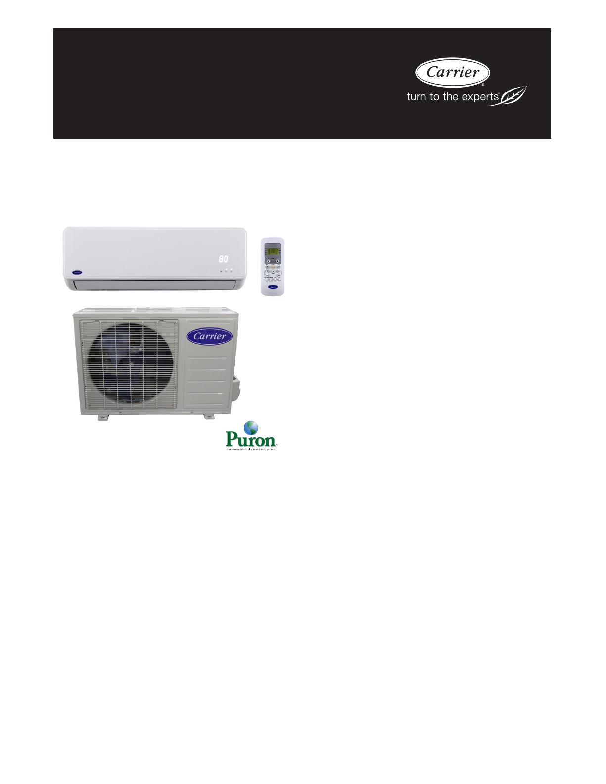
40MFC / 38MFC
40MFQ / 38MFQ
High---Wall Ductless Split System
Sizes 09 to 22
Product Data
INDUSTRY LEADING
FEATURES / BENEFITS
A PERFECT BALANCE BETWEEN
BUDGET LIMITS, ENERGY SAVINGS AND
COMFORT.
The 38/40MFC(Q) series ductless split systems are a matched
combination of an outdoor condensing unit and an indoor fan coil
unit connected only by refrigerant tubing and wires.
The fan coil is mounted on the wall, near the ceiling. This
selection of fan coils permits creative solutions to design problems
such as:
S Add--ons to current space (an office or family room
addition)
S Special space requirements
S When changes in the load cannot be handled by the
existing system.
S When adding air conditioning to spaces that are heated
by hydronic or electric heat and have no ductwork.
S Historical renovations or any application where
preserving the look of the original structure is essential.
The ideal compliment to your ducted system when it is impractical
or prohibitively expensive to use ductwork.
These compact indoor fan coil units take up very little space in the
room and do not obstruct windows. The fan coils are attractively
styled to blend with most room decors. Advanced system
components incorporate innovative technology to provide reliable
cooling performance at low sound levels.
Page 2

LOW SOUND LEVELS
When noise is a concern, the ductless split systems are the answer.
The indoor units are whisper quiet. There are no compressors
indoors, either in the conditioned space or directly over it, and
there is none of the noise usually generated by air being forced
through ductwork.
When sound ordinances and proximity to neighbors demand quiet
operation, the 38MFC,MFQ unit is the right choice: The advanced,
horizontal airflow design distributes air more evenly over the coil.
SECURE OPERATION
If security is an issue, outdoor and indoor units are connected only
by refrigerant piping and wiring to prevent intruders from crawling
through ductwork. In addition, since 38MFC,MFQ units can be
installed close to an outside wall, coils are protected from vandals
and severe weather.
FAST INSTALLATION
This compact ductless split system is simple to install. A mounting
bracket is standard with the indoor units and only wire and piping
need to be run between indoor and outdoor units. These units are
fast and easy to install ensuring minimal disruption to customers in
the home or workplace. This makes the 38/40MFC,MFQ ductless
split systems the equipment of choice, especially in retrofit
situations.
SIMPLE SERVICING AND
MAINTENANCE
Removing the top panel on outdoor units provides immediate
access to the control compartment, providing a service technician
access to check unit operation. In addition, the draw--thru design of
the outdoor section means that dirt accumulates on the outside
surface of the coil. Coils can be cleaned quickly from the inside
using a pressure hose and detergent.
On all indoor units, service and maintenance expense is reduced
due to easy--to--use cleanable filters. In addition, these high wall
systems have extensive self--diagnostics to assist in
troubleshooting.
BUILT--IN RELIABILITY
Ductless split system indoor and outdoor units are designed to
provide years of trouble--free operation.
The high wall indoor units include protection against freeze--up
and high evaporator temperatures on heat pumps.
The condensing units on heat pumps are protected by a three
minute time delay before the compressor will start the over--current
protection and the high temperature protection.
INDIVIDUAL ROOM COMFORT
Maximum comfort is provided because each space can be
controlled individually based on usage pattern. The air sweep
feature provided permits optimal room air mixing to eliminate hot
and cold spots for occupant comfort. In addition, year--round
comfort can be provided with heat pumps.
ECONOMICAL OPERATION
The ductless split system design allows individual room heating or
cooling when required. There is no need to run large supply--air
fans or chilled water pumps to handle a few spaces with unique
load patterns. In addition, because air is moved only in the space
required, no energy is wasted moving air through ducts.
EASY--TO--USE CONTROLS
The high-- wall units have microprocessor-- based controls to
provide the ultimate in comfort and efficiency. The user friendly
wireless remote control provides the interface between user and the
unit.
ACCESSORIES
Customizing these ductless split systems to your application is
easily accomplished.
Adding a condensate pump accessory to the high wall fan coil
provides installation flexibility.
OPTIONAL WIRED CONTROLLER
AGENCY LISTINGS
All systems are listed with AHRI (Air Conditioning, Heating &
Refrigeration Institute), and ETL.
2
Page 3
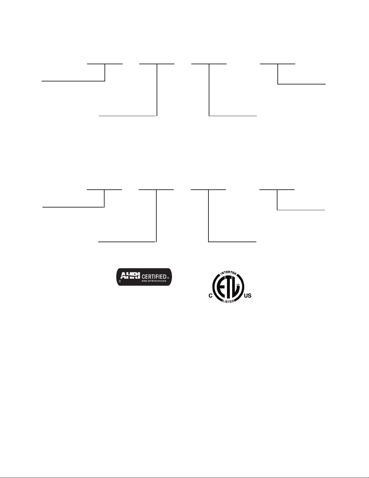
MODEL NUMBER NOMENCLATURE
INDOOR UNIT
40= Fan Coil Un it
38 = Ai r --- C o o l e d C o n d e n s e r
40 MFC 1
Unit Type
MFC --- Coolin g O n l y
MFQ --- Hea t P u m p
009
Nominal Capacity
009 --- 3/ 4 To n
012 --- 1 T o n
017 --- 1 --- 3/7 T o n (HP)
018 --- 1 --- 1/2 T o n (AC )
022 --- 1 --- 5/6 T o n s
--- --- ---
OUTDOOR UNIT
38 MFC 1
Unit Type
MFC --- Coolin g O n l y
MFQ --- Hea t P u m p
009
Nominal Capacity
009 --- 3/ 4 To n
012 --- 1 T o n
017 --- 1 --- 3/7 T o n (HP)
018 --- 1 --- 1/2 T o n (AC )
022 --- 1 --- 5/6 T o n s
--- --- ---
Volt age
1 --- 1 1 5 --- 1 --- 6 0
3 --- 2 0 8 --- 2 3 0 --- 1 --- 6 0
Volt age
1--- 1 1 5 --- 1 --- 6 0
3--- 2 0 8 --- 2 3 0 --- 1 --- 6 0
Use of the AHRI Certified
TM Mark indicates a
manufacturer’s
participation in the
program For verification
of certification for individual
products, go to
www.ahridirectory.org.
3
Page 4
STANDARD FEATURES AND ACCESSORIES
Ease Of Installation
Mounting Brackets S
Low Voltage Controls S
Comfort Features
Microprocessor Controls S
Wired Remote Control A
Wireless Remote Control S
Automatic Horizontal Air Sweep S
Air Direction Control S
Auto Restart Function S
Cold Blow Protection On Heat Pumps S
Freeze Protection Mode On Heat Pumps S
Turb o Mode S
Silence Mode S
Auto Changeover On Heat Pumps S
Energy Saving Features
Sleep Mode S
Stop/Start Timer S
Safety And Reliability
3MinuteTimeDelayForCompressor S
Over Current Protection For Compressor S
Indoor Coil Freeze Protection S
Indoor Coil High Temp Protection in Heating Mode S
Condenser High Temp Protection in Cooling Mode S
Ease Of Service And Maintenance
Cleanable Filters S
Diagnostics S
Liquid Line Pressure Taps S
Application Flexibility
Condensate Pumps A
Crankcase Heater S
Legend
SStandard
A Accessory
INDOOR UNITS
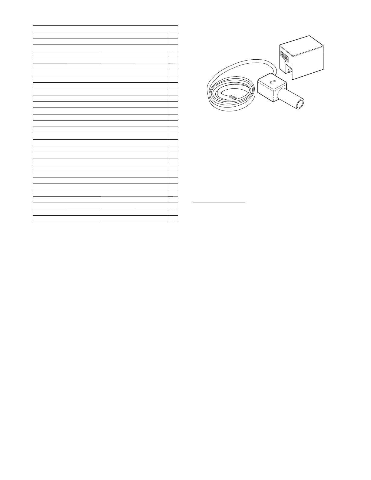
On high wall fan coils, the condensate pump has a lift capability of
12 ft (3.6 m) on the discharge side with the pump mounted in the
fan coil or 6 ft (1.8 m) on the suction side if the pump is remote
mounted. The pump is recommended when adequate drain line
pitch cannot be provided, or when the condensate must move up to
exit.
NOTE: An external 115v power source will be required to run the
pump on unit sizes 9k and 12k.
OUTDOOR UNITS
Crankcase Heater
Standard on all unit sizes. Heater clamps around compressor oil
stump.
A07892
Fig. 1 – Condensate Pump Accessory
4
Page 5
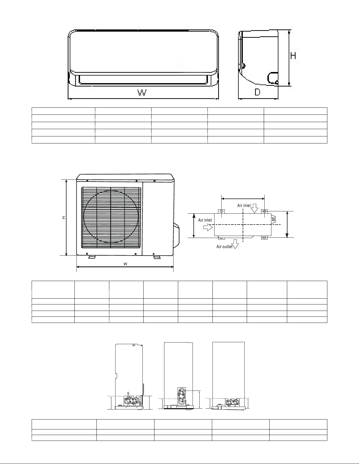
DIMENSIONS -- INDOOR
Unit Size W in (mm) D in (mm) H in (mm) Operating Weight lb (kg)
9K 26.8 (680) 7.0 (178) 10.0 (255) 15.4 (7)
12K 30.3 (770) 7.4 (188) 10.0 (255) 16.5 (7.5)
17K HP / 18K AC 35.6 (905) 7.8 (198) 10.8 (275) 19.8 (9)
22K 40.6 (1030) 8.6 (218) 12.4 (315) 26.4 (12)
DIMENSIONS -- OUTDOOR
A14343
L1
L2
Model W in (mm) D in (mm) H in (mm) L1 in (mm) L2 in (mm)
HP
Operating
Weight lb (kg)
D
AC
Operating
Weight lb (kg)
9K 30.7 (780) 9.8 (250) 21.2 (540) 21.6 (549) 10.9 (276) 70.5 (32.0) 58.4 (26.5)
12K 30.7 (780) 9.8 (250) 21.2 (540) 21.6 (549) 10.9 (276) 70.5 (32.0) 61.7 (28.0)
17K HP / 18K AC 29.9 (760) 11.2 (285) 23.2 (590) 20.9 (530) 11.4 (290) 82.7 (37.5) 76.0 (47.0)
22K 33.3 (845) 12.6 (320) 27.6 (700) 22.0 (560) 13.2 (335) 103.6 (47.0) 98.1 (44.5)
SERVICE VALVE LOCATIONS
9/12K
17/18K
22K
A14344
Service Valve Locations
J 4.37 (111) 4.37 (111) 4.09 (104) 4.13 ( 105)
K 4.61 (117) 4.61 (117) 6.34 (161) 4.13 (105)
J
9K
in. (mm)
K
J
K
12K
in. (mm)
J
18K
in. (mm)
K
A14408
22K
in. (mm)
5
Page 6
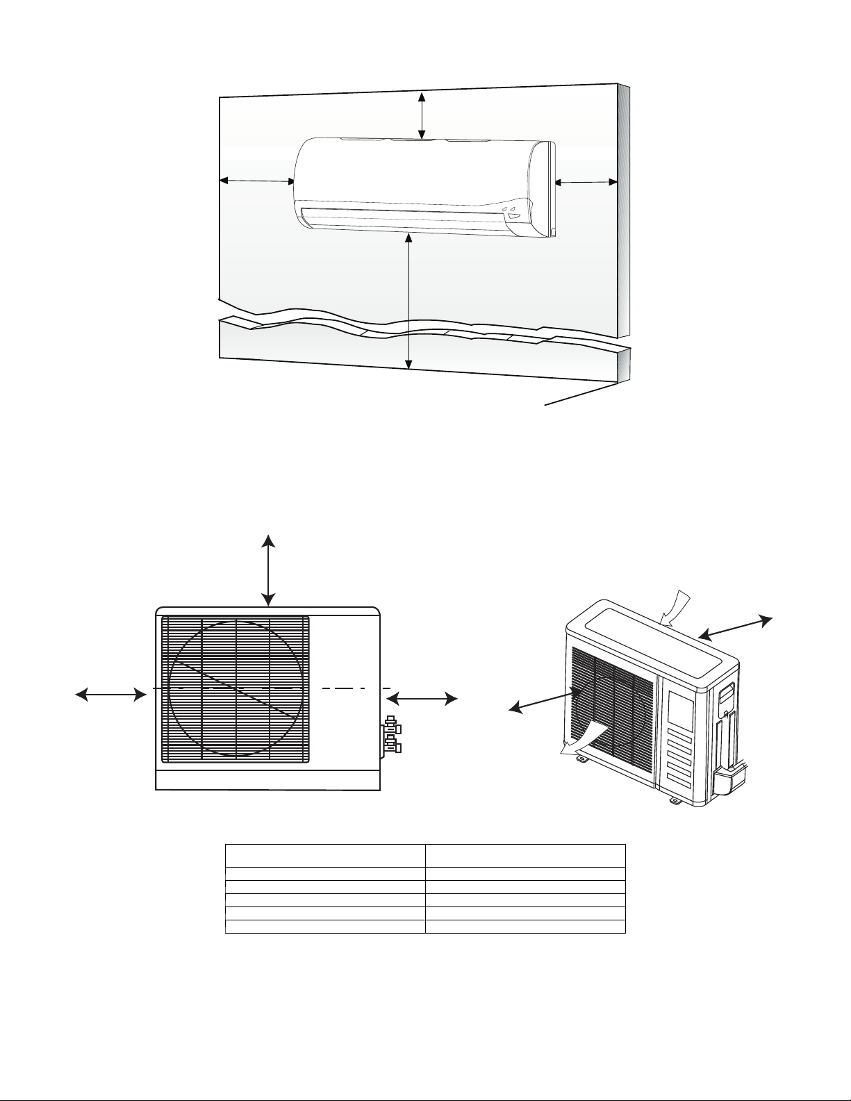
CLEARANCES -- INDOOR
"
5
(0.13m)
min.
CEILING
6" (0.15m) min.
(1.8m)
6'
FLOOR
Fig. 2 – Indoor Unit Clearance
5
"
(0.13m)
min.
A07891
CLEARANCES -- OUTDOOR
A
D
B
Air-outlet
UNIT
A 24 (610)
B 24 (610)
C 80 (2032)
D 12 (305)
E 24 (610)
Fig. 3 – Outdoor Unit Clearance
Minimum Value
in. (mm)
Air-inlet
E
C
A07894
6
Page 7
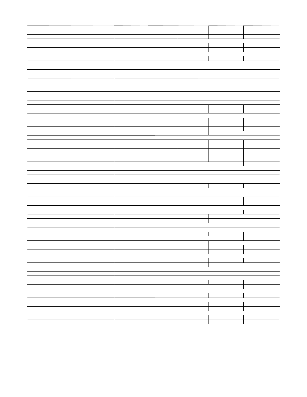
SPECIFICATIONS -- COOLI NG ONLY UNITS (MFC SERIES)
System
Size (KBTU/Hr) 09 12 18 22
Outdoor Model 38MFC009---1 38MFC012---1 38MFC012---3 38MFC018---3 38MFC022---3
Indoor Model 40MFC009---1 40MFC012---1 40MFC012---3 40MFC018---3 40MFC022---3
AHRI Performance Ratings*
Cooling Rated Capacity Btu/h 9,000 12,000 18,000 22,000
Cooling Cap. Range Min - Max Btu/h 4,000-10,000 4,500-13,000 5,500-19,000 6,500-24,000
SEER 15
EER 10 9 8.5 10
Operating Range
Cooling O utdoor DB Min - Max °F 14 - 115
Cooling Indoor DB Min -Max °F 63 - 90
Controls
Wireless (°C, °F, Convertible) Standard - Convertible
Wired (°C, °F, Convertible) Optional: KSACN0101CAC
Electrical
System Voltage-PH-Hz 115 -1 -60 208-230-1-60
Control Voltage 0-15V DC
Power Supply Indoor unit powered from outdoor unit
Outdoor - MCA 19 19 10 14 16
Outdoor - Fuse Rating (MOCP) 30 30 15 20 25
Outdoor Motor
Rpm/CFM 1000 / 945 940 / 945 860 / 1050 930 / 1390
Diameter (in) ... No. of Blades 15.8 … 3 16.7 … 3 18.3 … 3
Motor (hp) 0.31 0.33 0.68 0.72
Capacitor (µF) / voltage 6 / 250V 2.5 / 400 - 450v 2.5 / 450v
Indoor Motor
Motor Watts/ HP 15 / 0.02 15 / 0.02 20 / 0.027 28 / 0.038 45 / 0.061
Rpm/CFM (High) 1200 / 192 1200 / 230 1200 / 232 1200 / 348 1200 / 547
Rpm/CFM (Medium) 1050 / 160 1050 / 194 1050 / 193 1050 / 294 1050 / 458
Rpm/CFM (Low) 900 / 131 900 / 158 900 / 157 900 / 236 900 / 368
Blower Diameter / Length (in) 3.7 / 21.3 3.9 / 28.7 4.2 / 30.7
Capacitor (µF) 3 1.5 3
Refrigerant
Refrigerant Type R410A
Design Pressure (PSIG) 550
Metering Device Capillary Tube in Outdoor Unit
Charge (lb) 1.34 1.43 1.87 2.60
Refrigerant Lines
Connection Type Flare
Pipe Connection Size - Liquid (In) OD 1/4 3/8
Pipe Connection Size - Suction (In) OD 3/8 1/2 5/8
Condensate Drain OD / ID (in) 0.65 / 0.63
Maximum Piping Length (ft) 65 98
Max Lift (Fan Coil Above) (ft) 25 30
Max Drop (Fan Coil Below) (ft) 25 30
Compressor
Type Rotary
Model DA108X1C-20FZ3 DA130M1C-31FZ DA150S1C-20FZ
Oil Charge (POE –oz (g)) 16.9 (480) 17.6 (500)
Capacitor 45µF / 250VAC 6µF / 450VAC None
Rated Current (RLA) 5.3 3.95 9.7
Locked Rotor Amp (LRA) 10 14 17
Outdoor Coil
Face Area (sq. ft.) 4.10 6.10 7.67 11.16
No. Rows 1 1.5 2
Fins per inch 21
Circuits 2 4
Indoor Coil
Face Area (sq. ft.) 2.53 2.98 1.61 5.29
No. Rows 1/2 2
Fins per inch 20 21
Circuits 2 4 5
Dimensions - Outdoor
Dimensions(WXHXD)In 35.8 x 23 x 13.2 34.9 x 25.4 x 14 38.0 x 29.7 x 15.6
NetWeight(lbs.) 58.4 61.7 76.0 98.1
Dimensions - Indoor
Dimensions(WXHXD)In 26.8 x 10.0 x 7.0 30.3 x 10.0 x 7.4 35.6 x 10.8 x 7.8 40.6 x 12.4 x 8.6
NetWeight(lbs.) 15.4 16.5 19.8 26.4
*Air Conditioning, Heating & Refrigeration Institute
---Ra tings are net value s reflecting the effects of circulating fan heat. Ra tings are
based on: Cooling Standard: 80 _F (26.67_C) db, 67_F (19.44_C) wb air
entering indoor unit and 95_F(35_C) db air entering outdoor unit. High
Temperature Heating Standard: 70_F (21.11_C) db air enteri ng indoor unit and
47_F (8.33_C) db, 43_F (6.11_C) wb ai r e ntering outdoor unit.
--- Ratings are based on 25 ft. (7.62 m) of interconnecting refrigerant lines.
--- All system ratings are based on fan coil units operating at high fan speed.
Consult Specification tables for airflows at all available fan speeds.
Legend
SEER --- Seasonal Energy Efficiency Ratio
EER --- Energy Efficiency Ratio
MCA --- Minimum Circuit Amps
MOCP --- M a x . Ove r --- C u r r e nt P r o t e cti o n
7
Page 8
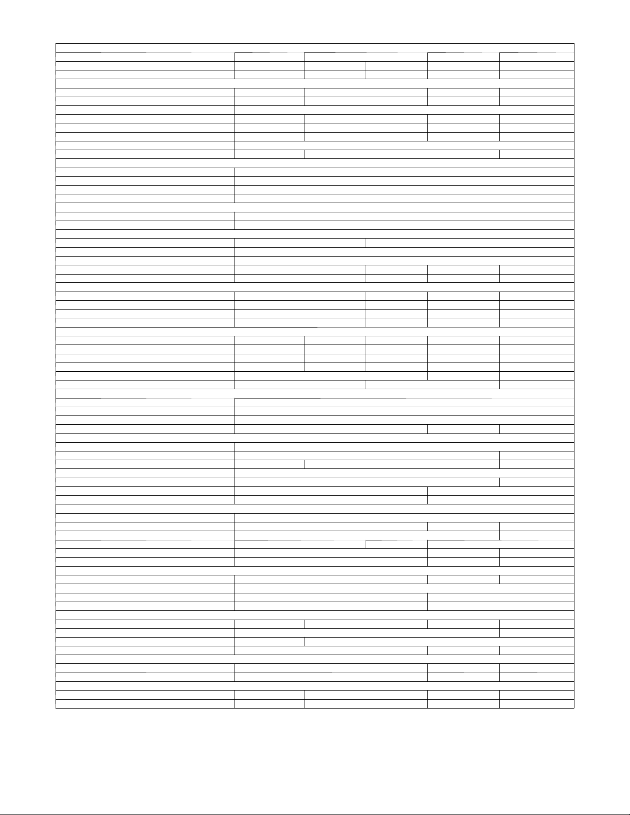
SPECIFICATI ONS -- HEAT PUMP UNITS (MFQ SERIES)
System
Size (KBTU/Hr) 09 12 17 22
Outdoor Model 38MFQ009---1 38MFQ012---1 38MFQ012---3 38MFQ017---3 38MFQ022---3
Indoor Model 40MFQ009---1 40MFQ012---1 40MFQ012---3 40MFQ017---3 40MFQ022---3
AHRI Performance Ratings*
Cooling Rated Capacity Btu/h 9,000 12,000 17,000 22,000
Cooling Cap. Range Min - Max Btu/h 4,000-10,000 4,500-13,000 5,500-19,000 6,500-24,000
SEER 15
EER 10.5 10 9 9.5
Heating Rated Capacity Btu/h 9,000 12,000 18,000 22,000
Heating Cap. Range Min - Max Btu/h 4,000-10,500 4,500-13,000 5,500-19,500 6,500-24,500
HSPF 8.2
COP Btuh, W 8.1 8.0 9.7
Operating Range
Cooling O utdoor DB Min - Max °F 14 - 115
Heating Outdoor DB Min - Max °F 5-75
Cooling Indoor DB Min - Max °F 63 - 90
Heating Indoor DB Min - Max °F 32 - 86
Controls
Wireless (°C, °F, Convertible) Standard - Convertible
Wired (°C, °F, Convertible) Optional: KSACN0101CAC
Electrical
System Voltage-PH-Hz 115 -1 -60 208-230-1-60
Control Voltage 0-15V DC
Power Supply Indoor unit powered from outdoor unit
Outdoor - MCA 19 10 14 16
Outdoor - Fuse Rating (MOCP) 30 15 20 25
Outdoor Motor
Rpm/CFM 1000 / 945 940 / 945 860 / 1050 930 / 1390
Diameter (in) ... No. of Blades 15.8 … 3 16.7 … 3 18.3 … 3
Motor (hp) 0.31 0.33 0.68 0.72
Capacitor (µF) 6 2.5
Indoor Motor
Motor Watts/ HP 15 / 0.02 15 / 0.02 20 / 0.027 28 / 0.038 45 / 0.061
Rpm/CFM (High) 1200 / 192 1200 / 230 1200 / 232 1200 / 348 1200 / 547
Rpm/CFM (Medium) 1050 / 160 1050 / 194 1050 / 193 1050 / 294 1050 / 458
Rpm/CFM (Low) 900 / 131 900 / 158 900 / 157 900 / 236 900 / 368
Blower Diameter / Length (in) 3.7 / 21.3 3.9 / 28.7 4.2 / 30.7
Capacitor (µF) 3 1.5 3
Refrigerant
Refrigerant Type R410A
Design Pressure (PSIG) 550
Metering Device Capillary Tube in Outdoor Unit
Charge (lb) 2.6 2.87 3.52
Refrigerant Lines
Connection Type Flare
Pipe Connection Size - Liquid (In) OD 1/4 3/8
Pipe Connection Size - Suction (In) OD 3/8 1/2 5/8
Condensate Drain OD / ID (in) 0.65 / 0.63
Maximum Piping Length (ft) 65 98
Max Lift (Fan Coil Above) (ft) 25 30
Max Drop (Fan Coil Below) (ft) 25 30
Compressor
Type Rotary
Model DA108X1C-20FZ3 DA130M1C-31FZ DA150S1C-20FZ
Oil Charge (POE –oz (g)) 16.9 (480) 17.6 (500)
Capacitor 45µF / 250VAC 6µF / 450VAC None
Rated Load Amps (RLA) 5.3 3.95 9.7
Locked Rotor Amp (LRA) 10 14 17
Outdoor Coil
Face Area (sq. ft.) 8.19 7.81 11
No. Rows 2
Fins per inch 17 18
Circuits 3 4
Indoor Coil
Face Area (sq. ft.) 2.53 2.98 1.61 5.29
No. Rows 1/2 2
Fins per inch 20 21
Circuits 2 4 5
Dimensions - Outdoor
Dimensions(WXHXD)In 35.8 x 23 x 13.2 34.9 x 25.4 x 14 38.0 x 29.7 x 15.6
NetWeight(lbs.) 70.5 82.7 103.6
Dimensions - Indoor
Dimensions(WXHXD)In 26.8 x 10.0 x 7.0 30.3 x 10.0 x 7.4 35.6 x 10.8 x 7.8 40.6 x 12.4 x 8.6
NetWeight(lbs.) 15.4 16.5 19.8 26.4
*Air Conditioning, Heating & Refrigeration Institute
---Ra tings are net value s reflecting the effects of circulating fan heat. Ra tings are
based on: Cooling Standard: 80 _F (26.67_C) db, 67_F (19.44_C) wb air
entering indoor unit and 95_F(35_C) db air entering outdoor unit. High
Temperature Heating Standard: 70_F (21.11_C) db air enteri ng indoor unit and
47_F (8.33_C) db, 43_F (6.11_C) wb ai r e ntering outdoor unit.
--- Ratings are based on 25 ft. (7.62 m) of interconnecting refrigerant lines.
--- All system ratings are based on fan coil units operating at high fan speed.
Consult Specification tables for airflows at all available fan speeds.
Legend
SEER --- Seasonal Energy Efficiency Ratio
EER --- Energy Efficiency Ratio
HSPF --- Heating Seasonal Performance Factor
COP --- Coefficient of Performance
MCA --- Minimum Circuit Amps
MOCP --- M a x . Ove r --- C u r r e nt P r o t e cti o n
8
Page 9
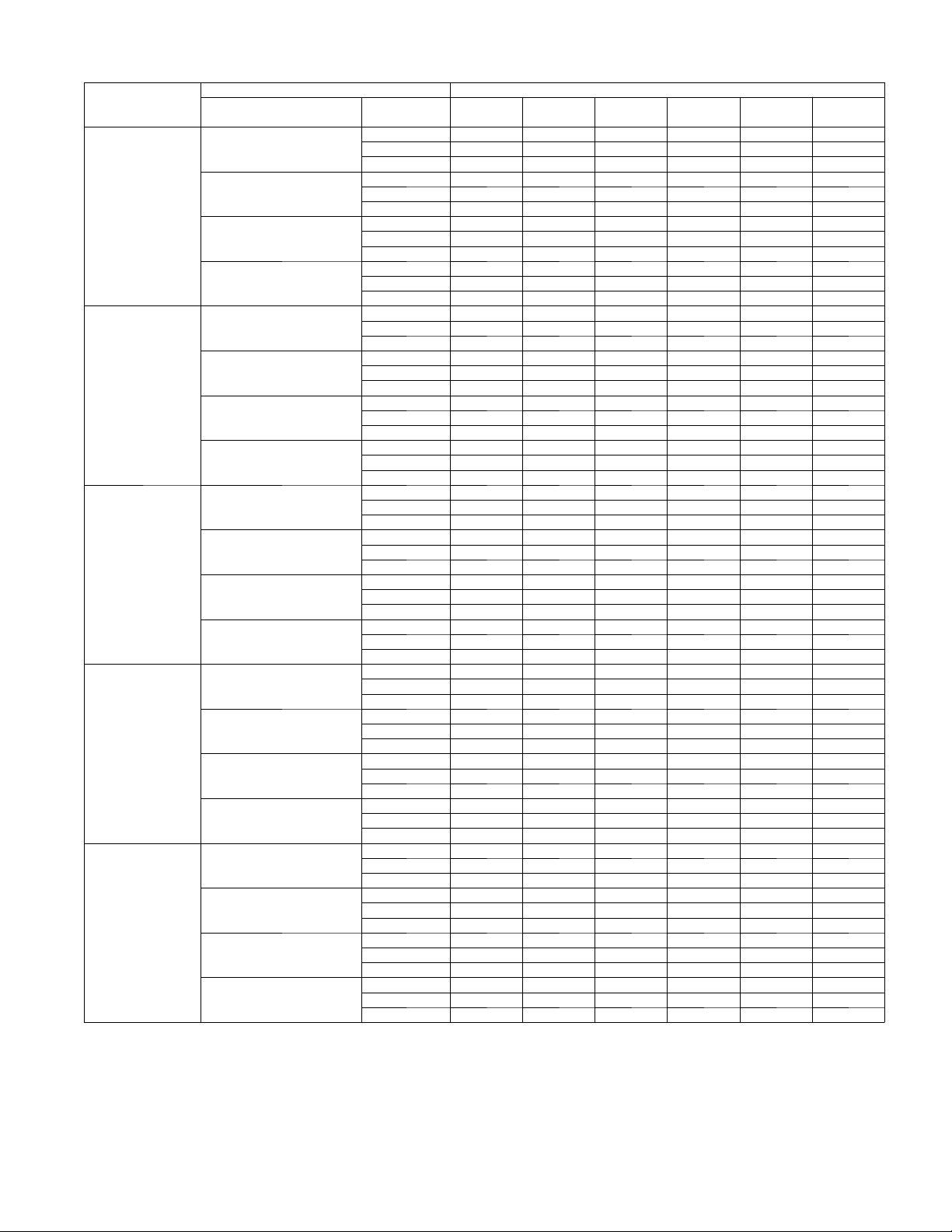
COOLING PERFORMANCE DATA -- 38/40MFC (COOLING ONLY)
Model
38 ---40MFC
009
012
(115v)
012
(208--- 230V)
018
022
LEGEND
DB --- Dry Bulb
W B --- Wet B u l b
TC --- Total Net Cooling Capacity (1000 Btu/hour)
SC --- Sensible Capacity (1000 Btu/hour)
I n pu t --- Total Po w e r (kW)
Indoor Conditions
DB/WB ° F
75.2/62.6
80.6/66.2
89.6/73.4
75.2/62.6
80.6/66.2
89.6/73.4
75.2/62.6
80.6/66.2
89.6/73.4
75.2/62.6
80.6/66.2
89.6/73.4
75.2/62.6
80.6/66.2
89.6/73.4
Cooling Outdoor conditions (DB) ° F
69.8/59
69.8/59
69.8/59
69.8/59
69.8/59
(BTU/h) 77 86 95 104 113 122
TC 5.71 7.90 8.88 7.45 6.20 5.18
SC 3.70 5.22 6.04 5.23 4.50 3.85
Input 0.48 0.76 1.00 0.98 0.95 0.90
TC 6.12 8.51 9.70 8.30 7.02 5.91
SC 3.93 5.54 6.46 5.69 5.00 4.42
Input 0.48 0.77 1.01 1.00 0.97 0.92
TC 6.55 9.35 10.69 9.01 7.43 6.08
SC 4.25 6.06 7.04 6.12 5.26 4.50
Input 0.49 0.79 1.03 1.02 0.99 0.94
TC 6.67 9.86 11.75 10.36 8.95 7.62
SC 4.03 5.94 7.11 6.39 5.72 5.15
Input 0.49 0.79 1.05 1.05 1.03 0.99
TC 5.94 8.63 10.38 8.52 5.60 4.68
SC 3.65 5.41 6.69 5.67 3.85 3.30
Input 0.58 0.97 1.35 1.29 0.99 0.94
TC 6.37 9.29 11.34 9.48 6.35 5.34
SC 3.88 5.74 7.16 6.16 4.29 3.79
Input 0.58 0.97 1.37 1.31 1.01 0.97
TC 6.82 10.21 12.50 10.30 6.71 5.50
SC 4.20 6.27 7.81 6.64 4.51 3.86
Input 0.59 0.99 1.39 1.34 1.03 0.99
TC 6.95 10.77 13.73 11.84 8.09 6.89
SC 3.98 6.15 7.88 6.93 4.90 4.41
Input 0.59 1.00 1.42 1.38 1.07 1.03
TC 5.92 8.58 10.33 8.47 5.57 4.66
SC 3.59 5.32 6.57 5.57 3.79 3.25
Input 0.57 0.95 1.33 1.27 0.97 0.93
TC 6.34 9.24 11.28 9.43 6.32 5.32
SC 3.81 5.64 7.03 6.05 4.21 3.72
Input 0.58 0.96 1.35 1.30 1.00 0.95
TC 6.78 10.16 12.44 10.24 6.68 5.47
SC 4.13 6.17 7.67 6.52 4.43 3.79
Input 0.59 0.98 1.37 1.32 1.02 0.97
TC 6.91 10.72 13.66 11.79 8.05 6.85
SC 3.91 6.04 7.75 6.80 4.82 4.34
Input 0.58 0.98 1.40 1.36 1.06 1.02
TC 12.34 14.95 14.96 10.83 8.16 6.65
SC 7.90 9.77 10.05 7.52 5.85 4.89
Input 1.25 1.73 2.01 1.70 1.49 1.38
TC 13.22 16.10 16.34 12.06 9.25 7.59
SC 8.38 10.37 10.75 8.17 6.51 5.60
Input 1.25 1.74 2.03 1.73 1.52 1.42
TC 14.15 17.70 18.02 13.10 9.79 7.80
SC 9.08 11.33 11.73 8.80 6.85 5.71
Input 1.28 1.78 2.08 1.76 1.55 1.45
TC 14.42 18.66 19.80 15.07 11.79 9.78
SC 8.61 11.10 11.85 9.18 7.44 6.53
Input 1.26 1.79 2.12 1.82 1.62 1.52
TC 17.19 19.41 19.49 16.59 14.03 11.96
SC 11.68 13.45 13.88 12.21 10.67 9.33
Input 1.49 1.92 2.23 2.22 2.18 2.12
TC 18.43 20.91 21.28 18.47 15.90 13.66
SC 12.39 14.28 14.85 13.27 11.86 10.70
Input 1.49 1.93 2.26 2.26 2.23 2.18
TC 19.72 22.99 23.47 20.06 16.81 14.05
SC 13.43 15.61 16.20 14.29 12.49 10.90
Input 1.52 1.97 2.31 2.31 2.28 2.23
TC 20.09 24.24 25.79 23.07 20.26 17.61
SC 12.72 15.29 16.36 14.91 13.57 12.46
Input 1.50 1.98 2.35 2.38 2.37 2.33
9
Page 10
COOLING PERFORMANCE DATA -- 38/40MFQ (HEAT PUMP)
Model
38 ---40MFQ
009
012
(115v)
012
(208--- 230V)
017
022
LEGEND
DB --- Dry Bulb
W B --- Wet B u l b
TC --- Total Net Cooling Capacity (1000 Btu/hour)
SC --- Sensible Capacity (1000 Btu/hour)
I n pu t --- Total Po w e r (kW)
Indoor Conditions
DB/WB ° F
75.2/62.6
80.6/66.2
89.6/73.4
75.2/62.6
80.6/66.2
89.6/73.4
75.2/62.6
80.6/66.2
89.6/73.4
75.2/62.6
80.6/66.2
89.6/73.4
75.2/62.6
80.6/66.2
89.6/73.4
Cooling Outdoor conditions (DB) ° F
69.8/59
69.8/59
69.8/59
69.8/59
69.8/59
(BTU/h) 77 86 95 104 113 122
TC 5.29 7.79 8.75 7.35 6.11 5.11
SC 3.38 5.07 5.86 5.08 4.36 3.74
Input 0.43 0.73 0.95 0.93 0.90 0.86
TC 5.67 8.39 9.57 8.18 6.92 5.83
SC 3.58 5.38 6.27 5.52 4.85 4.29
Input 0.43 0.73 0.96 0.95 0.92 0.88
TC 6.07 9.22 10.54 8.89 7.32 6.00
SC 3.88 5.88 6.83 5.94 5.11 4.37
Input 0.44 0.75 0.98 0.97 0.94 0.90
TC 6.18 9.72 11.59 10.22 8.82 7.51
SC 3.68 5.76 6.90 6.20 5.55 5.00
Input 0.44 0.75 1.00 1.00 0.98 0.94
TC 6.14 8.92 10.16 8.80 5.79 4.84
SC 3.76 5.57 6.52 5.84 3.97 3.40
Input 0.56 0.92 1.22 1.23 0.94 0.90
TC 6.59 9.60 11.09 9.80 6.56 5.52
SC 3.99 5.91 6.98 6.35 4.41 3.90
Input 0.56 0.93 1.23 1.25 0.96 0.92
TC 7.05 10.56 12.23 10.64 6.94 5.68
SC 4.33 6.46 7.61 6.84 4.65 3.97
Input 0.57 0.95 1.26 1.28 0.98 0.94
TC 7.18 11.14 13.44 12.24 8.36 7.12
SC 4.10 6.33 7.69 7.13 5.05 4.54
Input 0.56 0.95 1.28 1.32 1.02 0.99
TC 6.14 8.91 10.15 8.80 5.79 4.84
SC 3.73 5.53 6.47 5.79 3.94 3.38
Input 0.57 0.94 1.24 1.25 0.96 0.91
TC 6.58 9.60 11.09 9.80 6.56 5.52
SC 3.96 5.87 6.92 6.29 4.38 3.87
Input 0.57 0.94 1.25 1.27 0.98 0.94
TC 7.05 10.56 12.23 10.64 6.94 5.68
SC 4.29 6.41 7.55 6.78 4.61 3.94
Input 0.58 0.96 1.28 1.30 1.00 0.96
TC 7.18 11.13 13.44 12.24 8.36 7.12
SC 4.06 6.28 7.62 7.08 5.01 4.51
Input 0.57 0.97 1.30 1.34 1.04 1.00
TC 12.58 15.24 15.25 11.04 8.32 6.78
SC 8.34 10.30 10.60 7.93 6.18 5.16
Input 1.19 1.65 1.92 1.62 1.42 1.32
TC 13.48 16.41 16.66 12.30 9.43 7.74
SC 8.85 10.94 11.35 8.62 6.87 5.91
Input 1.19 1.66 1.94 1.65 1.45 1.35
TC 14.43 18.04 18.37 13.35 9.97 7.96
SC 9.59 11.95 12.37 9.28 7.23 6.02
Input 1.22 1.70 1.98 1.68 1.48 1.38
TC 14.70 19.03 20.18 15.36 12.02 9.97
SC 9.08 11.72 12.50 9.69 7.85 6.89
Input 1.21 1.71 2.02 1.73 1.54 1.45
TC 16.27 18.37 18.44 15.70 13.27 11.32
SC 10.99 12.65 13.06 11.49 10.03 8.78
Input 1.46 1.88 2.19 2.18 2.14 2.08
TC 17.44 19.79 20.14 17.48 15.05 12.93
SC 11.65 13.43 13.97 12.48 11.16 10.07
Input 1.46 1.89 2.22 2.21 2.19 2.14
TC 18.67 21.75 22.21 18.98 15.91 13.30
SC 12.63 14.68 15.24 13.45 11.75 10.25
Input 1.49 1.93 2.26 2.26 2.23 2.18
TC 19.01 22.94 24.40 21.84 19.17 16.66
SC 11.97 14.39 15.39 14.03 12.76 11.73
Input 1.47 1.94 2.31 2.33 2.32 2.29
10
Page 11
HEATING PERFORMANCE DATA -- 38/40MFQ (HEAT PUMP)
Model
38 ---40MFQ
009
012
(115v)
012
(208--- 230v)
017
022
LEGEND
DB --- Dry Bulb
TC --- Total Net Cooling Capacity (1000 Btu/hour)
I n pu t --- Total Po w e r (kW)
Indoor Conditions
Heating Outdoor conditions (DB) ° F
DB ° F
59
64.4
69
71.6
59
64.4
69
71.6
59
64.4
69
71.6
59
64.4
69
71.6
59
64.4
69
71.6
(BTU/h) 53.6 44.6 39.2 32.0 24.8 19.4
TC 11.30 11.00 11.91 7.70 6.44 6.20
Input 1.20 1.17 1.28 1.11 1.03 1.08
TC 10.64 10.44 11.53 7.32 6.76 5.97
Input 1.23 1.17 1.30 1.18 1.14 1.19
TC 10.58 10.55 11.43 6.95 6.25 6.10
Input 1.26 1.21 1.34 1.18 1.11 1.17
TC 9.84 10.26 10.90 5.90 6.31 5.89
Input 1.16 1.20 1.34 1.17 1.12 1.23
TC 12.81 12.12 12.00 7.76 6.48 6.25
Input 1.44 1.37 1.37 1.18 1.10 1.16
TC 12.06 11.50 11.61 7.37 6.80 6.01
Input 1.47 1.37 1.39 1.26 1.21 1.27
TC 12.00 11.62 11.51 7.00 6.30 6.15
Input 1.51 1.41 1.43 1.26 1.19 1.25
TC 11.15 11.30 10.98 5.94 6.36 5.94
Input 1.40 1.40 1.43 1.25 1.20 1.31
TC 12.79 12.11 11.98 7.75 6.48 6.24
Input 1.44 1.37 1.37 1.18 1.10 1.16
TC 12.05 11.49 11.59 7.36 6.80 6.00
Input 1.47 1.37 1.40 1.26 1.22 1.27
TC 11.98 11.61 11.49 6.99 6.29 6.14
Input 1.51 1.42 1.43 1.26 1.19 1.25
TC 11.14 11.29 10.97 5.94 6.35 5.93
Input 1.40 1.41 1.43 1.26 1.20 1.31
TC 20.22 19.47 18.52 11.97 10.01 9.65
Input 2.19 2.12 2.04 1.76 1.64 1.73
TC 19.04 18.48 17.92 11.38 10.51 9.28
Input 2.24 2.12 2.08 1.87 1.81 1.90
TC 18.94 18.66 17.77 10.81 9.72 9.49
Input 2.30 2.19 2.13 1.87 1.77 1.87
TC 17.61 18.15 16.95 9.18 9.82 9.16
Input 2.13 2.18 2.13 1.87 1.79 1.96
TC 24.12 23.15 21.97 14.20 11.87 11.44
Input 2.19 2.11 2.03 1.74 1.62 1.71
TC 22.71 21.97 21.26 13.50 12.46 11.01
Input 2.24 2.11 2.06 1.86 1.79 1.88
TC 22.59 22.19 21.07 12.82 11.53 11.26
Input 2.30 2.18 2.11 1.86 1.76 1.85
TC 21.00 21.59 20.11 10.89 11.64 10.87
Input 2.13 2.16 2.12 1.85 1.77 1.94
11
Page 12
APPLICATION DATA
UNIT SELECTION
Select equipment to either match or be slightly less than anticipated
peak load. This provides better humidity control, fewer unit cycles,
and less part-- load operation.
For units used in spaces with high sensible loads, base equipment
selection on unit sensible load, not on total anticipated load. Adjust
for anticipated room wet bulb temperature to avoid undersizing
equipment.
UNIT MOUNTING (INDOOR)
Refer to unit Installation Instructions for further details.
Unit leveling -- For reliable operation, units should be level in all
planes.
Clearance -- Provide adequate clearance for airflow as shown in
Fig. 2.
Unit location -- Select a location which will provide the best air
circulation for the room.
These units should be positioned as high as possible on the wall for
best air circulation. The unit return and discharge should not be
obstructed by furniture, curtains, or anything which may cause unit
short cycling or air recirculation. Place the unit in the middle of the
selected wall (if possible). Use an outside wall, if available, to
make piping easier, and place the unit so it faces the normal
location of room occupants.
UNIT MOUNTING (OUTDOOR)
Refer to unit Installation Instructions for further details.
Unit leveling -- For reliable operation, units should be level in all
planes.
Clearance -- Minimum clearance, as shown in Fig. 3, must be
provided for airflow. The condensing units are designed for
free--blow application. Air inlets and outlets should not be
restricted.
Unit location -- A location which is convenient to installation and
not exposed to strong wind.
A location which can bear the weight of outdoor unit and where
the outdoor unit can be mounted in a level position.
Do not install the indoor or outdoor units in a location with special
environmental conditions. For those applications, contact your
Carrier representative.
MOUNTING TEMPLATE
Refer to unit Installation Instructions for further details.
The fan coil units are furnished with mounting to mark the location
of the wiring, and refrigeration line hole locations.
SUPPORT
Adequate support must be provided to support the weight of all fan
coils. Refer to the Physical Data section for fan coil weights, and
the base unit dimensional drawings for the location of mounting
brackets.
SYSTEM OPERATING CONDITIONS
Operating Range
Min / Max °F (°C)
Cooling Heating
Outdoor DB 14 / 115 (-10 / 46) 5 / 75 (-15 / 24)
Indoor DB 63 / 90 (17 / 32) 32 / 86 (0 / 30)
Indoor WB 59 / 84 (15 / 29) 4.1 / 70.7 (-15.5 / 21.5)
Non-Operating Temperature Range
Min / Max °F (°C)
Indoor/Outdoor DB 32 / 86 (0 / 30)
NOTE: Reference the Product Installation Instructions for more information.
METERING DEVICES
These units have capillary tube metering devices in the outdoor
unit.
DRAIN CONNECTIONS
Install drains to meet local sanitation codes. If adequate gravity
drainage cannot be provided, unit should be equipped with
accessory condensate pump. High wall fan coil unit condensate
pumps have a maximum lift of 10’ (3.05 m) for 9k and 12k units
and 25’ (7.62 m) for 18k and 22k units.
See physical dimension tables for drain sizes.
NOTE: High wall fan coil units have internal condensate traps.
A trap is not required.
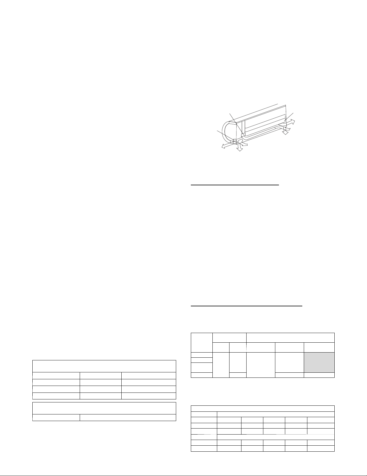
Drain connections may be routed through alternate locations on
mostfancoilsasshowninFig.4.
Pipe cover
Pipe holder
1
2
Right back piping
Pipe cover
4
Left piping
3
Left back piping
Right piping
Fig. 4 – Piping Locations
A14349
REFRIGERANT LINES
General refrigerant line sizing:
1. The 38MFC/MVQ units are shipped with a full charge of
R410A refrigerant. All charges, line sizing, and capacities
are based on runs of 25 ft (7.6 m). For runs over 25 ft (7.6
m), consult long--line section on this page for proper charge
adjustments.
2. Refrigerant lines should not be buried in the ground. If it is
necessary to bury the lines, not more than 36--in (914 mm)
should be buried. Provide a minimum 6--in (152 mm)
vertical rise to the service valves to prevent refrigerant
migration.
3. Both lines must be insulated. Use a minimum of 1/2--in.
(12.7 mm) thick insulation. Closed--cell insulation is
recommended in all long--line applications.
4. Special consideration should be given to isolating
interconnecting tubing from the building structure. Isolate
the tubing so that vibration or noise is not transmitted into
the structure.
Long Line Applications, 38MFC Units:
1. No change in line sizing is required.
2. Add refrigerant per table below.
ADDITIONAL CHARGE TABLE
Tot a l L i ne
Unit
Size
9K
12K
18K AC
17K HP
22K 98 0.32 0.32
Length ft
Min Max
65
10
3. Reduction in capacity due to long lines can be calculated
from the chart below.
CAPACITY LOSS
Line Length ft (m)
Cooling: 25 (7.5) 33 (10) 49 (15) 65 (20) 98(30)
9&12K 1% 2% 5% 7% --18&22K 1% 2% 4% 6% 8%
Heating:
9&12K 1% 2% 7% 11% --17&22K 1% 2% 6% 10% 15%
Capacity,% Loss
Additional Charge, oz/ft.
10 - -- 25
( 3 --- 8 )
None
ft (m)
> 2 5 --- 6 5
( 8 --- 2 0 )
0.16
> 6 5 --- 9 8
( 2 0 --- 3 0 )
12
Page 13
WIRING
A
w
Recommended Connection Method for Power and Communication Wiring (To minimize communication wiring
ence)
Power Wiring:
The main power is supplied to the outdoor unit. The field supplied
connecting cable from the outdoor unit to indoor unit consists of
three (3) wires and provides the power for the indoor unit. Two
wires are high voltage AC power and one is a ground wire.
Consult your local building codes and the NEC (National
Electrical Code) or CEC (Canadian Electrical Code) for special
requirements.
All wires must be sized per NEC or CEC and local codes. Use
Electrical Data table MCA (minimum circuit amps) and MOCP
(maximum over current protection) to correctly size the wires and
the disconnect fuse or breakers respectively.
Per caution note, only copper conductors with a minimum 300 volt
rating and 2/64--inch thick insulation must be used.
Communication Wiring:
A separate shielded copper conductor only, with a minimum 300
volt rating and 2/64--inch thick insulation, must be used as the
communication wire from the outdoor unit to the indoor unit.
To minimize voltage drop of the control wire, use the following
wire size and maximum lengths shown in the chart below:
Wire Size
18 AWG 50 (15)
16 AWG 50 (15) to 100 (30)
Alternate Connection Method for Power and Communication
Wiring (May not prevent communication wiring interfer
The main power is supplied to the outdoor unit. The field supplied
connecting cable from the outdoor unit to indoor unit consists of
four (4) wires and provides the power and communication signals
for the indoor unit. Two conductors are for power wiring (L1/L2,
or L/N), one is a ground wire, and one is a DC communication
wire.
Consult your local building codes and the NEC (National
Electrical Code) or CEC (Canadian Electrical Code) for special
requirements. All power wires must be sized per NEC or CEC and
local codes. Use Electrical Data table MCA (minimum circuit
amps) and MOCP (maximum over current protection) to correctly
size the wires and the disconnect fuse or breakers respectively.
Per caution note, only copper conductors with a minimum 300 volt
rating and 2/64--inch thick insulation must be used.
interfer-
Length
ft (m)
ence)
!
EQUIPMENT DAMAGE HAZARD
Failure to follow this caution may result in equipment
damage or improper operation.
S Be sure to comply with local codes while running wire
from indoor unit to outdoor unit.
S Every wire must be connected firmly. Loose wiring
may cause terminal to overheat or result in unit
malfunction. A fire hazard may also exist. Therefore,
be sure all wiring is tightly connected.
S No wire should be allowed to touch refrigerant tubing,
compressor or any moving parts.
S Disconnecting means must be provided and shall be
located within sight and readily accessible from the air
conditioner.
S Connecting cable with conduit shall be routed through
hole in the conduit panel.
The main power is supplied to the outdoor unit. the field supplied
connecting cable from the outdoor unit to indoor unit consists of
four wires and provides the power for the indoor unit as well as the
communication signal between the outdoor unit and indoor unit.
Two wires are high voltage AC power (L1 and L2), one is a
ground wire, and one is a DC communication wire.
CAUTION
CONTROL SYSTEM
The 40MFC/MFQ unit is equipped with a microprocessor control
to perform two functions:
1. Provide safety for the system
2. Control the system and provide optimum levels of comfort
and efficiency
The main microprocessor is located on the control board of the fan
coil unit (outdoor units have a microprocessor too) with
thermistors located in the fan coil air inlet and on the indoor coil.
Heat pump units have a thermistor on the outdoor coil. These
thermistors monitor the system operation to maintain the unit
within acceptable parameters and control the operating mode.
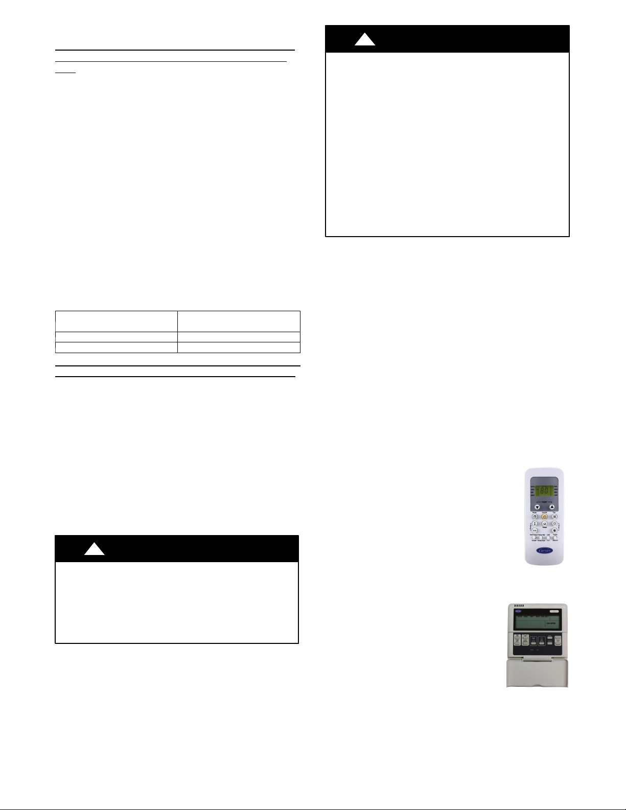
WIRELESS REMOTE CONTROL
1.
ireless remote control is supplied for
system operation of all high--wall units.
2. Each battery--operated wireless (infrared)
remote control may be used to control more
than one unit.
!
EQUIPMENT DAMAGE HAZARD
Failure to follow this caution may result in equipment
damage or improper operation.
S Wires should be sized based on NEC and local codes.
S Use copper conductors only with a minimum 300 volt
rating and 2/64 inch thick insulation.
CAUTION
WIRED REMOTE CONTROL (OPTIONAL)
P/N KSACN0101CAC
1. Optional wired remote controller used
for system operation of all high--wall
units.
2. Kit includes a wired remote controller
and a connecting cable.
3. Connect with wire terminal between
remote controller and indoor unit.
4. Display in _For_C and temperature
increments every 1_Forevery1_C.
13
Page 14
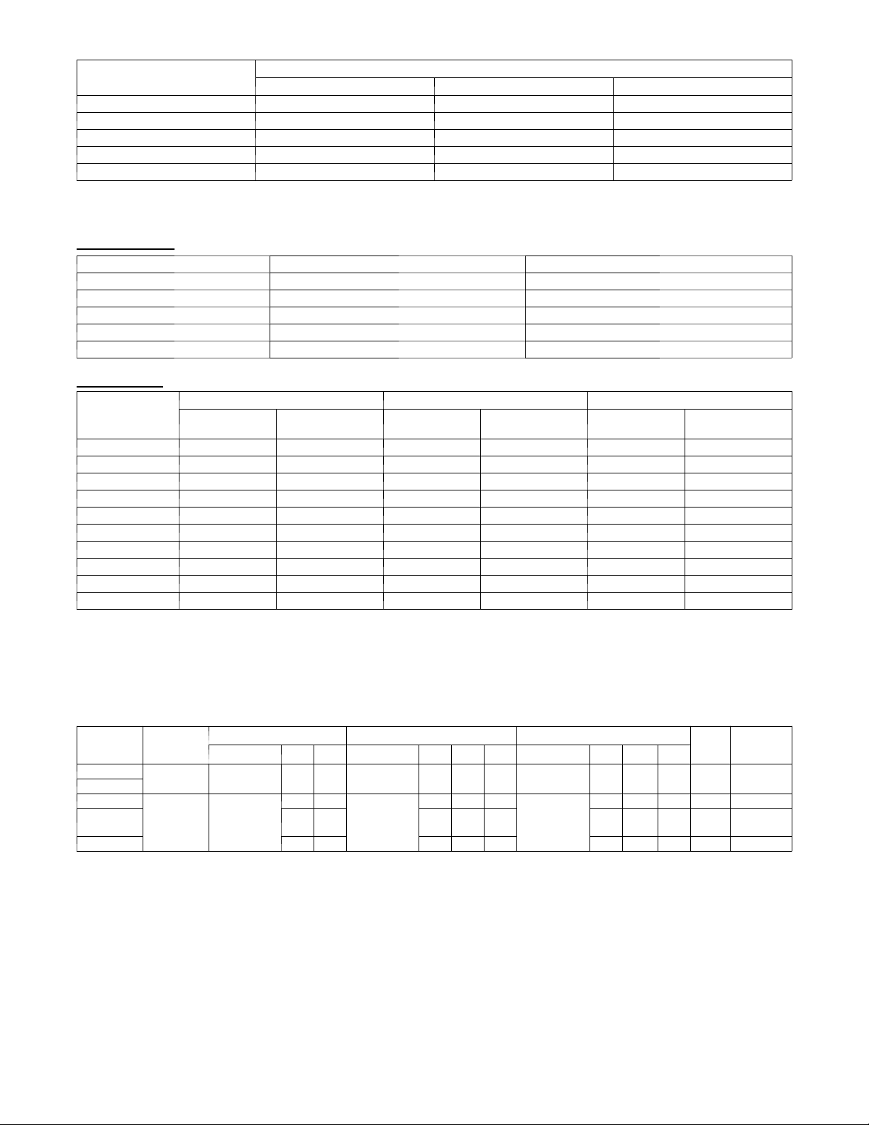
AIR THROW DATA
UNIT
CAPACITY
Low Medium High
009 115v 11 (3 .5) 15 (4.5) 21 (6.5)
012 115v 14 (4 .2) 17 (5.1) 23 (7.0)
012 208/230v 14 (4.2) 17 (5.1) 23 (7.0)
018 208/230v 16 (5.0) 20 (6.2) 28 (8.5)
022 208/230v 19 (5.7) 23 (7.0) 31 (9.5)
APPROXIMATE AIR THROW ft. (m)
SOUND RATINGS
Outdoor Units
Model Number Sound Power dBa Sound Pre ssure dBa
3 8 M FC(Q) 0 0 9 --- --- --- 1 67 57
3 8 M FC(Q) 0 1 2 --- --- --- 1 67 58
3 8 M FC(Q) 0 1 2 --- --- --- 3 67 58
38MFC017 / 38MFC018---------3 70 60
3 8 M FC(Q) 0 2 2 --- --- --- 3 72 61
Indoor Units
High Medium Low
Model Number
4 0 M FC009 --- --- --- 1 52 43 48 39 43 34
4 0 M FC012 --- --- --- 1 53 44 49 40 45 36
4 0 M FC012 --- --- --- 3 53 44 49 40 45 36
4 0 M FC018 --- --- --- 3 55 45 51 41 47 37
4 0 M FC022 --- --- --- 3 60 50 56 46 52 42
4 0 M FQ0 0 9 --- --- --- 1 52/49 (Clg/Htg) 43/40 (Clg/Htg) 48/44 (Clg/Htg) 39/35 (Clg/Htg) 43/ 39 (Clg/Htg) 34/30 (Clg/Htg)
4 0 M FQ0 1 2 --- --- --- 1 53/52 (Clg/Htg) 44/43 (Clg/Htg) 49/47 (Clg/Htg) 40/38 (Clg/Htg) 45/ 52 (Clg/Htg) 36/33 (Clg/Htg)
4 0 M FQ0 1 2 --- --- --- 3 53/51 (Clg/Htg) 44/42 (Clg/Htg) 49/45 (Clg/Htg) 40/36 (Clg/Htg) 45/ 40 (Clg/Htg) 36/31 (Clg/Htg)
4 0 M FQ0 1 7 --- --- --- 3 55/52 (Clg/Htg) 45/42 (Clg/Htg) 51/48 (Clg/Htg) 41/38 (Clg/Htg) 47/ 43 (Clg/Htg) 37/33 (Clg/Htg)
4 0 M FQ0 2 2 --- --- --- 3 60/56 (Clg/Htg) 50/46 (Clg/Htg) 56/52 (Clg/Htg) 46/42 (Clg/Htg) 52/48 (Clg/Htg) 42/38 (Clg/Htg)
NOTES:
1. Sound power r a tings ar e per AHRI 270 and AHRI 350
2. Sound pressure ratings are estimated sound pressure, 3 feet (.91 m) from the unit, based on sound power data.
Sound Power
dBa
Sound Pressure
dBa
Sound Power
dBa
Sound Pressure
dBa
Sound Power
dBa
Sound Pressure
dBa
ELECTRICAL DATA
OPER.
UNIT SIZE
9K
12K
12K
017K (HP)
018K (AC)
22K 9.7 17 0.6 0.72 53 0.4 0.061 45 16 25
*Permissible limits of the voltage range at which the unit will operate satisfactorily
LEGEND
FLA --- F u l l L o a d A m p s
LRA --- L o c k e d R o t o r A m p s
MCA --- Minimum Circuit Amps
RLA --- R a t e d L o a d A m p s
VOLTAGE
MAX / MIN*
127 / 104 115--- 1 --- 6 0 5.3 10 1 15 --- 1 --- 60 0.7 0.31 23 11 5 --- 1 --- 6 0 0.3 0.020 15 19 30
253 / 187 2 08 --- 23 0 --- 1 --- 6 0
COMPRESSOR OUTDOOR FAN INDOOR FAN
V --- P H --- H Z RLA LRA V --- P H --- H Z FLA HP W V --- P H --- H Z FL A HP W
5.3 10
3.95 14 0.6 0.68 50 0.3 0.038 28 14 20
2 08 --- 2 30 --- 1 --- 60
0.3 0.33 24
0.2 0.027 20 10 15
2 08 --- 2 30 --- 1 --- 60
14
MCA
MAX FUSE
CB AMP
Page 15
DISPLAY BO ARD
FAN C
A
PA
C
IT
OR
B
OAR
D
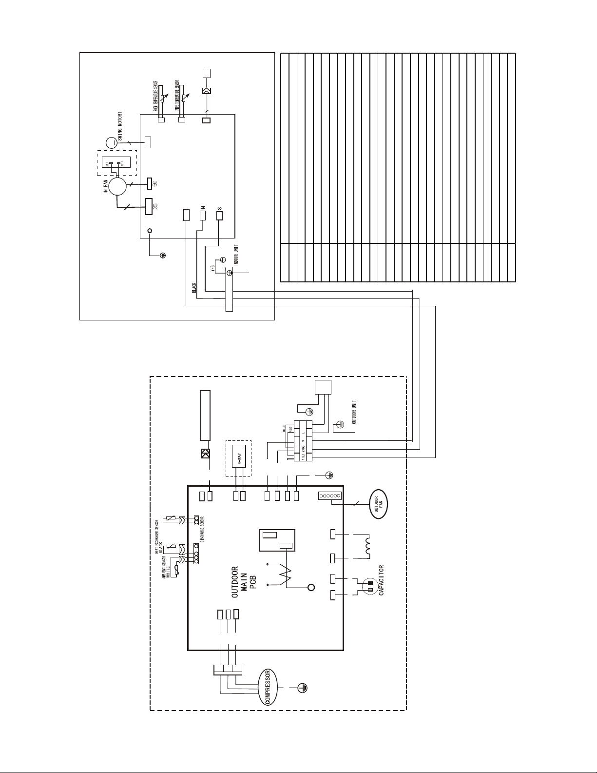
CODE PART NAME
L_IN FireWire L input terminal
CN11 Zero line N input terminal
CN16 Internal and external communication line interface
CN6 Indoor fan interface
CN4 Fan feedback interface
CN5 Stepper motor interface
P_1 Ground interface
CN8 Room temperature sensor interface
CN9 Pipe temperature sensor interface
CN10A Display interface
CN1 Electronic expansion valve interface
CN14 Compressor top temperature sensor (optional)
CN15 Exhaust temperature sensor
CN16 Outdoor temperature & amp; condenser pipe temperature sensor
CN10 DC fan output port (no)
CN19 AC fan output port
CN33 Electric heating wire line N
CN34 Electric heating wire line L
CN26,CN28 Four way valve c ontrol port
CN4 Power L input terminal
CN5 Power N input terminal
CN6 Ground wire
CN7 Communication line
CN8,CN9 Reactor connected line port
CN36,CN37 PFC capacitor connected line port
N-B Power L input terminal
CN17 Tes t pan el int erfac e
U V W Compressor connec tion port
8
CN9
5
M
N CAPA
FA
CITOR BO
A
M
~
R
D
Optional
3
CN5
4
6
CN8
3(2)
P_1
CN 2
L_IN
C N10A
CN11
CN16
INDOOR WIRING DIAGRAM
GND
YELLOW
RED
2020325B3267
S
N
L
T
HEATER, CRANKCASE
BLACK
CN33
CN34
CN15
CN16
2020375A5475
RED
U
BLUE
V
U
Dashed frame
parts only for heat
pump model.
CN26
CN28
W
V
RED
BLACK
W
Y/G
L
N
Power Input
N
Y/G
GND
L N S
BLUE
BROWN
YELLOW
CN7
CN5
Y/G
CN6
CN4
CN10(CN19)
5
Fig. 5 – Wiring Diagram 38/40MFC/MFQ009 / 38/40MFC/MFQ012 (115V)
RED
RY3
4
L2
CS
BLUE
CN9
N-A
REACTOR
RED
CN8
BLACK
L-B(CN36)
N-B
BLACK
L-A(CN37)
Y/G
OUTDOOR WIRING DIAGRAM
WIRING DIAGRAMSNO TAG
15
Page 16
DISPLAY BOARD
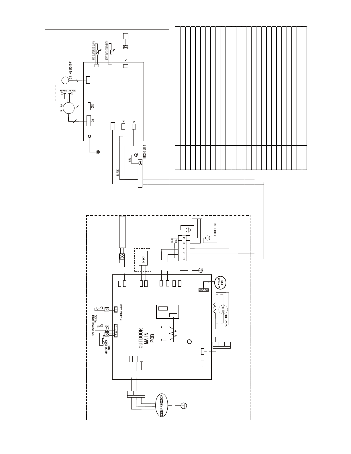
CODE PART NAME
L_IN FireWire L input terminal
CN11 Zero lin e N inp ut te rminal
CN16 Internal and external c ommunication line interface
CN6 Indoor fan interface
CN4 Fan feedback interface
CN5 Steppe r motor interfac e
P_1 Ground interface
CN8 Room temperature sensor interface
CN9 Pipe temperature sensor interface
CN10A Display interface
CN14 Compressor top temperature sensor (optional)
CN15 Exhaust temperature sensor
CN16 Outdoor temperature & c ondenser pipe temperature sensor
CN26,CN28 Four way valve control port
CN10 AC fan output port
CN32,CN34 Electric heating wire line N
CN31,CN33 Elec tric h eat ing wire line L
CN4 Power L input terminal
CN5 Po wer N inp ut te rminal
CN6 Ground wire
CN7 Co mmu nicatio n line
N-B Power L input terminal
CN2,CN3 Reactor c onnected line port
CN17 Test panel interface
U V W Compressor connection port
8
CN9
CN8
5
M
CN5
Optional
CN10A
3
M
~
2020328A7163
3(2)
L_IN
CN11
P_1
CN2
CN16
INDOOR WIRING DIAGRAM
GND
YELLOW
RED
S
L2
L1
Y/G
L
N
Power Input
Dashed frame
parts only for heat
HEATER, CRANKCASET
pump model.
Y/G
GND
L N S
BLUE
BROWN
BLACK
CN34
RED
CN33
CN28
CN26
YELLOW
CN7
CN5
Y/G
5
CN6
CN4
10
CN
WHITE
Fig. 6 – Wiring Diagram 38/40MFC/MFQ012 (208--230V)
4
Y/G
N-A
BLUE
CN3
CN2
BLACK
BLACK
BLACK
WHITE
BLACK
B
OUTDOOR WIRING DIAGRAM
20 20 37 5A5477
CN15
CN16
U
U
BLUE
RY3
L2
CS
W
V
RED
BLACK
V
W
WIRING DIAGRAMS (CONT.)
16
Page 17
DISPLAY BO ARD
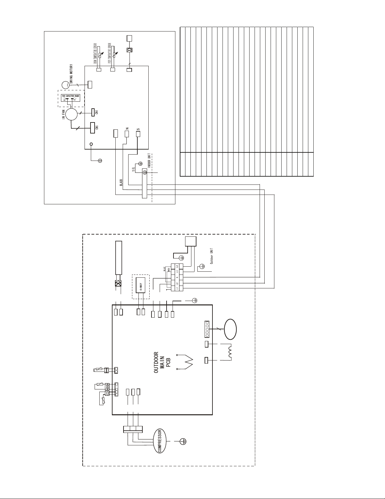
CODE PART NAME
L_IN FireWire L input terminal
CN11 Ze ro line N inpu t termin al
CN16 Internal and external communic ation line interface
CN6 Indoor fan interface
CN4 Fan feedback interface
CN5 Stepper motor interface
P_1 Ground interface
CN8 Room temperature sensor interface
CN9 Pipe temperature sensor interface
CN10 A Displa y inte rfac e
CN101 Compressor top temperature sensor (optional)
CN102 Exhaust temperature sensor
CN103 Outdoor temperature & c ondenser pipe temperature sensor
CN8,CN9 Four way valve control port
CN10 AC fan output port
CN4 Electric heating wire line N
CN7 Electric heating wire line L
CN13 Power L input terminal
CN12 Power N input terminal
CN14 G roun d wire
CN15 C ommun ica tion line
N-B Power L input terminal
CN11,CN22 Reactor connec ted line port
U V W Compressor connec tion port
8
CN9
5
CN8
M
CN5
Optional
CN10A
3
M
~
3(2)
2020328A7163
L_IN
CN11
P_1
CN2
CN16
INDOOR WIRING DIAGRAM
GND
YELLOW
RED
S
L2
L1
Y/G
L
N
Power Input
Dashed frame
parts only for heat
HEATER, CRANKCASE
T
pump model.
Y/G
GND
L N S
BLUE
BROWN
RED
BLACK
YELLOW
Y/G
CN 4
DISCHARGE SENSOR
HEAT EXCHANGER SENSOR
(BLACK)
AMBIENT
SENSOR
(WHITE)
2020378A3515
CN 7
CN 102
CN 103
CN 9
CN 8
W
V
U
RED
BLUE
BLACK
V
U
W
CN 15
CN 12
CN 13
CN 14
L2
Y/G
5(3)
CN10(CN10A)
CN11
CS
CN22
BLACK
BLACK
OUTDOOR
FAN
REACTOR
Fig. 7 – Wiring Diagram 38/40MFC018 -- 38/40MFQ017 (208--230V)
OUTDOOR WIRING DIAGRAM
WIRING DIAGRAMS (CONT.)
17
Page 18
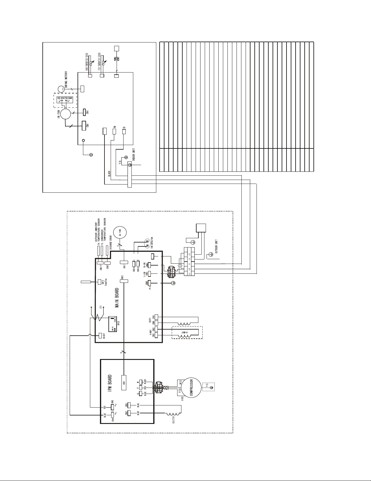
M
CODE PART NAME
L_IN FireWire L input terminal
CN11 Zero line N input terminal
CN16 Internal and external communication line interface
CN6 Indoor fan interface
CN4 Fan feedback interface
CN5 Stepper motor interface
P_1 Ground interface
CN8 Room temperature sensor interface
CN9 Pipe temperature sensor interfac e
CN10 A Disp lay int erfac e
CN12 Compressor top temperature sensor (optional)
CN7 Exhaust temperature sensor
CN17 Outdoor temperature & condenser pipe temperature sensor
CN1,CN2 Fou r way va lve c ont rol port
CN11,CN22 AC fan output port
CN10,CN13 Fan capacitor port
CN5 Elect ric h eatin g wire lin e N
CN6 Elect ric h eatin g wire lin e L
CN3 Power L input terminal
CN4 Power N input terminal
P1 Ground wire
CN15 Communication line
N-OUT1 Power N Onput terminal
RY2 POWER Power L Onput terminal
CN26 Test panel interface
CN4 Power L input terminal
CN5 Power N input terminal
CN2 CN3 Reactor connected line port
CN11 Bus voltage positive terminal
CN12 Bus voltage positive terminal
CN1 Main control board and power supply
CN6 Standby power interface
U V W Compressor connection port
M
~
2020328A7163
5
3
3(2)
Optional
DISPLAY BO ARD
8
CN9
CN8
CN5
P_1
C N10A
L_IN
CN11
CN2
YELLOW
RED
INDOOR WIRING DIAGRAM
CN16
GND
S
L2
L1
Y/G
L
N
Power Input
Y/G
GND
L N S
YELLOW
YELLOW
S
CN30
YELLOW
BLACK
RED
Y/G
BLUE
RED
Fig. 8 – Wiring Diagram 38/40MFC(Q)022 (208--230V)
CS
L-OUT
20 2037 9A41 84
HEATER, C RANKCASE
Dashed frame
parts only for heat
pump model.
OUTDOOR WIRING DIAGRAM
WIRING DIAGRAMS (CONT.)
18
Page 19
GUIDE SPECIFICATIONS
INDOOR WALL--MOUNTED DUCTLESS UNITS
Size Range: 3/4 to 1--5/6 Ton Nominal Cooling and Heating Capacity
Carrier Model Number: 40MFC/40MFQ
PART 1 -- GENERAL
1.01 System Description
Indoor, wall--mounted, direct--expansion fan coils are matched with
cooling only or heat pump outdoor unit .
1.02 Agency Listings
Unit shall be rated per AHRI Standards 210/240 and listed in the
AHRI directory as a matched system.
1.03 Delivery, Storage, And Handling
Units shall be stored and handled per unit manufacturer’s
recommendations.
1.04 Warranty (For Inclusion By Specifying
Engineer)
PART 2 -- PRODUCTS
2.01 Equipment
A. General:
Indoor, direct--expansion, wall--mounted fan coil. Unit shall be
complete with cooling/heating coil, fan, fan motor, piping
connectors, electrical controls, microprocessor control system, and
integral temperature sensing. Unit shall be furnished with integral
wall mounting bracket and mounting hardware.
B. Unit Cabinet:
Cabinet discharge and inlet grilles shall be attractively styled,
high--impact polystyrene. Cabinet shall be fully insulated for
improved thermal and acoustic performance.
C. Fans:
1. Fan shall be tangential direct--drive blower type with air
intake at the top of the unit and discharge at the bottom
front. Automatic, motor--driven vertical air sweep shall be
provided standard.
2. Air sweep operation shall be user selectable. The vertical
sweep may be adjusted (using the remote control) and the
horizontal air direction may be set manually.
D. Coil:
Coil shall be copper tube with aluminum fins and galvanized steel
tube sheets. Fins shall be bonded to the tubes by mechanical
expansion. A drip pan under the coil shall have a drain connection
for hose attachment to remove condensate. Condensate pan shall
have internal trap.
E. Motors:
Motors shall be open drip--proof, permanently lubricated ball
bearing with inherent overload protection. Fan motors shall be
3--speed.
F. C ont ro ls :
Controls shall consist of a microprocessor--based control system
which shall control space temperature, determine optimum fan
speed, and run self diagnostics. the temperature control range shall
be from 62_Fto86_F(17_Cto30_C) in increments of 1_For
1_C.
The unit shall have the following functions as a minimum:
1. An automatic restart after power failure at the same
operating conditions as at failure.
2. A timer function to provide a minimum 24--hour timer
cycle for system Auto Start/Stop.
3. Temperature--sensing controls shall sense return air
temperature.
4. Indoor coil freeze protection.
5. Wireless infrared remote control to enter set points and
operating conditions.
6. Automatic air sweep control to provide on or off activation
of air sweep louvers.
7. Dehumidification mode shall provide increased latent
removal capability by modulating system operation and set
point temperature.
8. Fan--only operation to provide room air circulation when no
cooling is required.
9. Diagnostics shall provide continuous checks of unit
operation and warn of possible malfunctions. Error
messages shall be displayed at the unit.
10. Fan speed control shall be user--selectable: high, medium,
low, or microprocessor controlled automatic operation
during all operating modes.
11. Automatic heating--to--cooling changeover in heat pump
mode. Control shall include deadband to prevent rapid
mode cycling between heating and cooling.
12. Indoor coil high temperature protection shall be provided to
detect excessive indoor discharge temperature when unit is
in heat pump mode.
G. Filters:
Unit shall have filter track with factory--supplied cleanable filters.
H. Electrical Requirements:
Indoor fan motor to operate on 115V on model sizes 009--012 and
on 208--230V on model sizes 012--022, power is supplied from
outdoor unit.
I. Operating Characteristics:
The 40MFC, MFQ system shall have a minimum listed SEER
(seasonal energy efficiency ratio) of 15 at AHRI conditions, and a
minimum HSPF of 8.2.
J. Refrigerant Lines:
All units should have refrigerant lines that can be oriented to
connect from the left, right or back of unit. Both refrigerant lines
need to be insulated.
K. Special Features (Field Installed):
1. Condensate Pump:
-- The condensate pump shall remove condensate from the
drain pan when gravity drainage cannot be used. Pump
shall be designed for quiet operation. Pump shall consist of
two parts: an internal reservoir/sensor assembly, and a
remote sound--shielded pump assembly. A liquid level
sensor in the reservoir shall stop cooling operation if the
liquid level in the reservoir is unacceptable.
19
Page 20
PART 1 -- GENERAL
1.01 System Description
A. Outdoor air--cooled split system compressor sections suitable
for on--the--ground, rooftop, wall hung or balcony mounting.
Units shall consist of a rotary compressor, an air--cooled coil,
propeller--type draw--through outdoor fan, reversing valve
(HP), accumulator (HP units), metering device(s), and control
box. Units shall discharge air horizontally as shown on the
contract drawings. Units shall function as the outdoor
component of an air--to --air cooling only, or heat pump system.
B. Units shall be used in a refrigeration circuit matched to ductless
cooling only or heat pump fan coil units.
1.02 Agency Listings
A. Unit construction shall comply with ANSI/ASHRAE 15, latest
revision, and with the NEC.
B. Units shall be evaluated in accordance with UL standard 1995.
C. Units shall be listed in the CEC directory.
D. Unit cabinet shall be capable of withstanding 500--hour salt
spray test per Federal Test Standard No. 141 (method 6061).
E. Air--cooled condenser coils shall be leak tested at 550 psig.
1.03 Delivery, Storage, And Handling
Units shall be shipped in one piece and shall be stored and handled
per unit manufacturer’s recommendations.
1.04 Warranty (For Inclusion By Specifying
Engineer)
PART 2 -- PRODUCTS
2.01 Equipment
A. General:
Factory assembled, single piece, air--cooled outdoor unit.
Contained within the unit enclosure shall be all factory wiring,
piping, controls, and the compressor.
B. Unit Cabinet:
1. Unit cabinet shall be constructed of galvanized steel,
bonderized and coated with a baked--enamel finish on
inside and outside.
2. Unit access panels shall be removable with minimal screws
and shall provide full access to the compressor, fan, and
control components.
3. Outdoor compartment shall be isolated and have an acoustic
lining to assure quiet operation.
C. Fans:
1. Outdoor fans shall be direct--drive propeller type, and shall
discharge air horizontally. Fans shall draw air through the
outdoor coil.
2. Outdoor fan motors shall be totally--enclosed, single phase
motors with class B insulation and permanently--lubricated
ball bearings. Motor shall be protected by internal thermal
overload protection.
GUIDE SPECIFICATIONS
HORIZONTAL DISCHARGE OUTDOOR UNITS
Size Range: 3/4 to 1--5/6 Ton Nominal Cooling and Heating Capacity
Carrier Model Number: 38MFC/38MFQ
3. Shaft shall have inherent corrosion resistance.
4. Fan blades shall be non metallic and shall be statically and
dynamically balanced.
5. Outdoor fan openings shall be equipped with PVC
metal/mesh coated protection grille over fan.
D. Compressor:
1. Compressor shall be fully hermetic rotary type.
2. Compressor shall be equipped with oil system, operating oil
charge, and motor. Internal overloads shall protect the
compressor from over--temperature and over--current.
3. Motor shall be NEMA rated class F, suitable for operation
in a refrigerant atmosphere.
4. Compressor assembly shall be installed on rubber vibration
isolators.
5. Compressors shall be single phase.
E. Outdoor Coil:
Coil shall be constructed of aluminum fins mechanically bonded to
seamless copper tubes, which are cleaned, dehydrated, and sealed.
F. Refrigeration Components:
Refrigerant circuit components shall include brass external liquid
line service valve with service gage port connections, suction line
service valve with service gage connection port, service gage port
connections on compressor suction and discharge lines with
Schrader type fittings with brass caps, accumulator, reversing
valve.
G. Controls and Safeties:
Operating controls and safeties shall be factory selected, assembled,
and tested. The minimum control functions shall include the
following:
1. Controls:
a. A time delay control sequence is provided standard through
the fan coil board.
b. Automatic outdoor--fan motor protection.
2. Safeties:
a. System diagnostics.
b. Compressor motor current and temperature overload
protection.
c. Outdoor fan failure protection.
H. Electrical Requirements:
1. Unit shall operate on single--phase, 60 Hz power at 115 v
for unit sizes 009-- 012 and 208--230v for unit sizes 012,
017, 018, and 022, as specified.
2. Unit electrical power shall be a single point connection.
3. Unit Control voltage to the indoor fan coil shall be 0--15V
DC.
4. All power and control wiring must be installed per NEC
and all local electrical codes.
5. Unit shall have high-- and low--voltage terminal block
connections.
Copyright 2014 Carrier Corp. D 7310 W. Morris St. D Indianapolis, IN 46231 Edition Date: 08/14
Manufacturer reserves the right to change, at any time, specifications and designs without notice and without obligations.
20
Catalog No: 38 --- 40MF ---02PD
R e p l a ce s : 38 --- 4 0 MF --- 0 1 PD
 Loading...