

Page 1
Carrier
International
Corporation
Installation, Operation,
and Maintenance Instructions
Important—Read Before Installing
Check the power supply: Voltage, frequency, and phase
must correspond to that specified on the unit rating plate.
The power supply must be able to handle the additional elec
trical load imposed by this equipment.
The Model 38GP Condensing Unit does not have a trans
former; therefore, the fan-coil or blower package trans
former (or another source) must be used as a low-voltage
supply. The low-voltage supply must have an additional
capacity of 15VA to handle the load imposed by this
equipment.
The compressor motor is equipped with em internal protec
tor. Excessive current or temperature wiU cause the protec
tor to open, giving the indication of an open circuit in the
motor winding. Sufi&cient time should be allowed for the
overload to reset before assuming the compressor has an
open winding.
The compressor motor is designed to start under low-load
conditions only (high- and low-side pressures equalized) and
within the specified operating voltage range. Make sure
that system pressures have equahzed before attempting to
start the unit. Equahzation takes approximately 3 minutes.
The owner should be informed not to short-cycle the unit
with the thermostat as this wiU cause the compressor to
tripout on overload.
Each condensing unit is shipped with a refrigerant charge
that is adequate for most systems using matching coils and
refrigerant tubing kits. This charge is adequate for up to 25
feet of interconnecting tubing. For tube lengths greater or
less than 25 feet, the refrigerant charge must be adjusted.
See Table II for charge quantity and refer to refrigeranttube sizing. Tables IV through VII, for the adjustment re
quirements.
NOTE: If additional refrigerant is needed, a crankcase heater
wül probably be required. (Refer to the appropriate refriger
ant-tube sizing table.) When a crankcase heater is used,
inform the homeowner that power must be turned on to the
air conditioning unit at least 12 hours before the thermostat
is turned to the COOLING position for spring startup.
A filter-drier is not normally required in the system when a
complete system is used (condensing unit, refrigerant tub
ing, and evaporator coil). For exceptions to this rule, see
Section II, “Installing Refrigerant Tubing,” of the Stand
ard Installation Practices booklet packaged with the unit.
To obtain optimum performance and efficiency with match
ing or mix-matched evaporator coils, it may be necessary to
change the metering device. See Table IX for necessary
changes.
^Carrier International Corporation 1984
38GP
(50-HZ)
Figure 1—Model 38GP
GENERAL
The condensing unit, as shipped from the factory, includes:
a compressor, a condenser fan and motor, hquid and suction
service valves, an air-cooled condenser coil, and all neces
sary electriceil controls.
The condensing unit is designed for use with matching
evaporator coils. An expansion valve is not required. How
ever, the unit can be used with a suitable evaporator coil
that uses an expansion valve with a pressure equalization
feature during the off cycle. Expansion valves with this fea
ture.are available from your Distributor.
Installation comprises the following steps (sections):
I. Locating the Unit
II. InstaUing Refrigerant Tubing
III. Leak Testing
IV. Purging (if required)
V. Evacuation (if required)
VI. Electrical Connections
VII. Checking Charge
VIII. Adjusting Charge
38GP-C12SI-CIC
Page 2
AIR IN
NOTE: Fan position on motor shaft should be as close to motor as possible without touching.
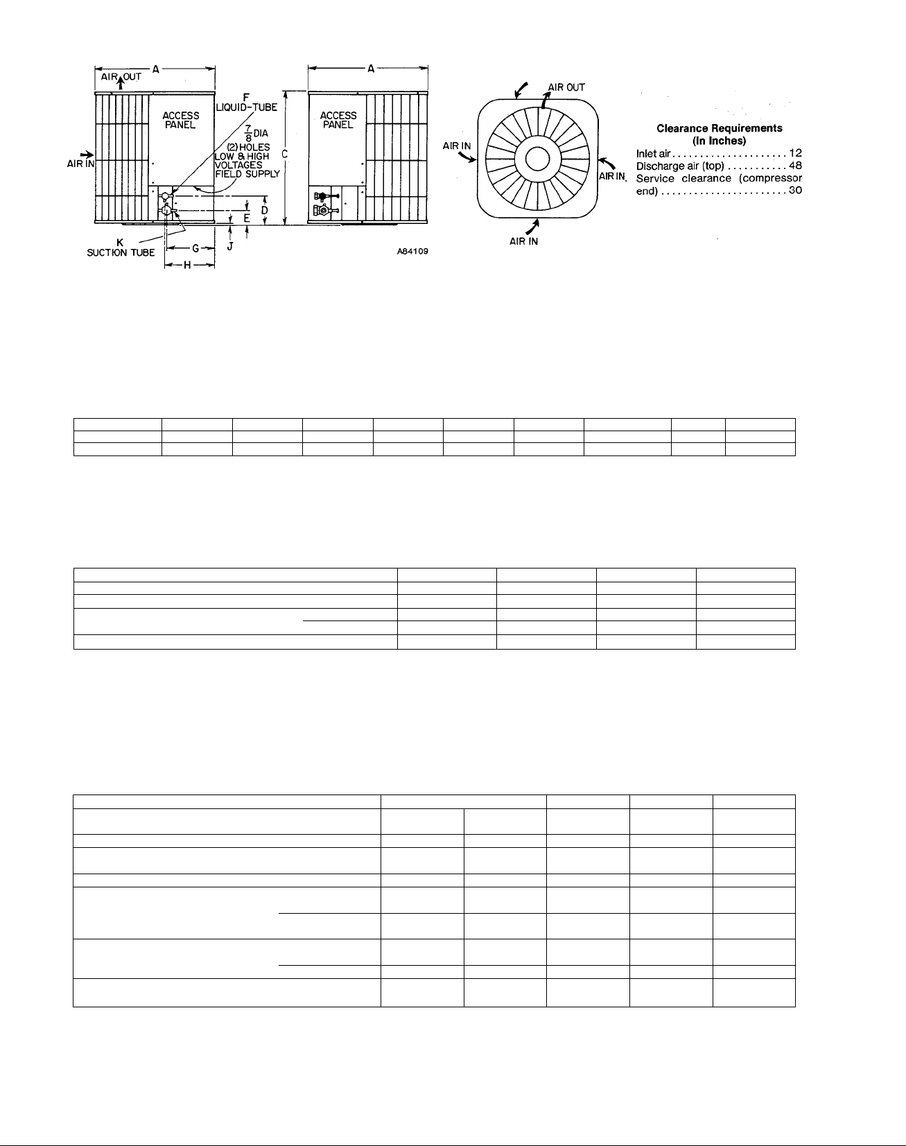
Figure 2—Dimensional Drawing
TABLE I—DIMENSIONS (In Inches)
Size
025
040, 047 & 054
----------X---------27-3/8 24-9/16 6-3/8 1-7/8 3/8
27-3/8 30-9/16 6-3/8 1-7/8 3/8
----------C----------
D
----------1----------
F G
11-9/16
11-9/16
H
11-3/4
11 -3/4
11/32 3/4
11/32
3/4
K
TABLE II—SPECIFICATIONS
Refrigerant Type R-22
Size 025
Factory Refrigerant Charge Lbs-oz 4-8
040
R-22 R-22
6-8 7-2
Refrigerant Tube^ Liquid 3/8 3/8
Connection Size (Compatible) Vapor 3/4 3/4
Approx Shipping Weight Lbs 155 200
♦Refer to appropriate refrigerant tube sizing table to determine correct liquid- and suction-tube diameters.
047
3/8
3/4
230
054
R-22
6-11
3/8
3/4
232
TABLE III—ELECTRIC CONNECTIONS
Nameplate
Size 025 040
Volts—Phase (60-Hertz) 230—1—50
Operating Voltage Range
207-253 360-440 360-440 360-440 360-440
400—3—50
400—3—50
Unit Ampacity for Elec
trical Conductor Sizing. 18.5 6.7 9.2 14.1
Total Unit Amps 15.1 5.6 7.6
Min Branch Circuit
Wire Size
Copper
Conductor^
AWG No.
Max Length
In Ftt
12 14 14 14
94 321 236 156 228
Largest Wire Size
Terminal Will
, Accommodate
Type Conn
AWG No. 6
Screw Screw
6 6 6 6
Screw
Max Branch. Circuit
Fuse Sizet
Amps 25
10
15
NOTE: Use copper wire only between disconnect switch and unit.
♦If other than 75° C copper conductor is used, determine size from unit-ampacity and the National Electric Code. Voltage drop of wire must be less
than 2% of unit rated voltage.
fLength shown is as measured one way along the wire path between the unit and service panel-for minimum 2% voltage drop.
$Sing)e-phase units may use fuses or HACFI-type circuit breakers of same size as noted.
047 054
400—3—50 400—3—50
15.4
11.5 12.5
12
Screw Lug
20 20
Page 3
All of the above steps are covered in general by the likenumbered sections of the Standard Installation Practices in
the back of this manual; therefore, this Installation Instruc
tion will contain only supplementary information applicable
to installing the condensing unit. It should be noted that
evacuation and purging are not normally required when a
complete matching system is installed. However, if any of
the component parts are subject to contamination, or if tub
ing kits and matching coUs are not used, the system must
be purged or evacuated.
NOTE; Be sure to adjust system airflow per requirements of
the fan-coil, evaporator coil, and condensing unit
combination.
In addition, the following sections should be reviewed by
the equipment owner;
IX. Sequence of Operation
X. Care and Maintenance
I. LOCATING THE UNIT
(Supplementary Instructions)
Select a location for the unit where water, ice, emd snow will
not fall from an overhang and damage the unit top or fan
blade. Care must be exercised to maintain the clearance
requirements listed on page 2 to assure proper access for
servicing and to avoid recirculation of condenser air.
II. INSTALLING REFRIGERANT TUBES
(Supplementary Instructions)
A. Determining Liquid-Tube Diameter
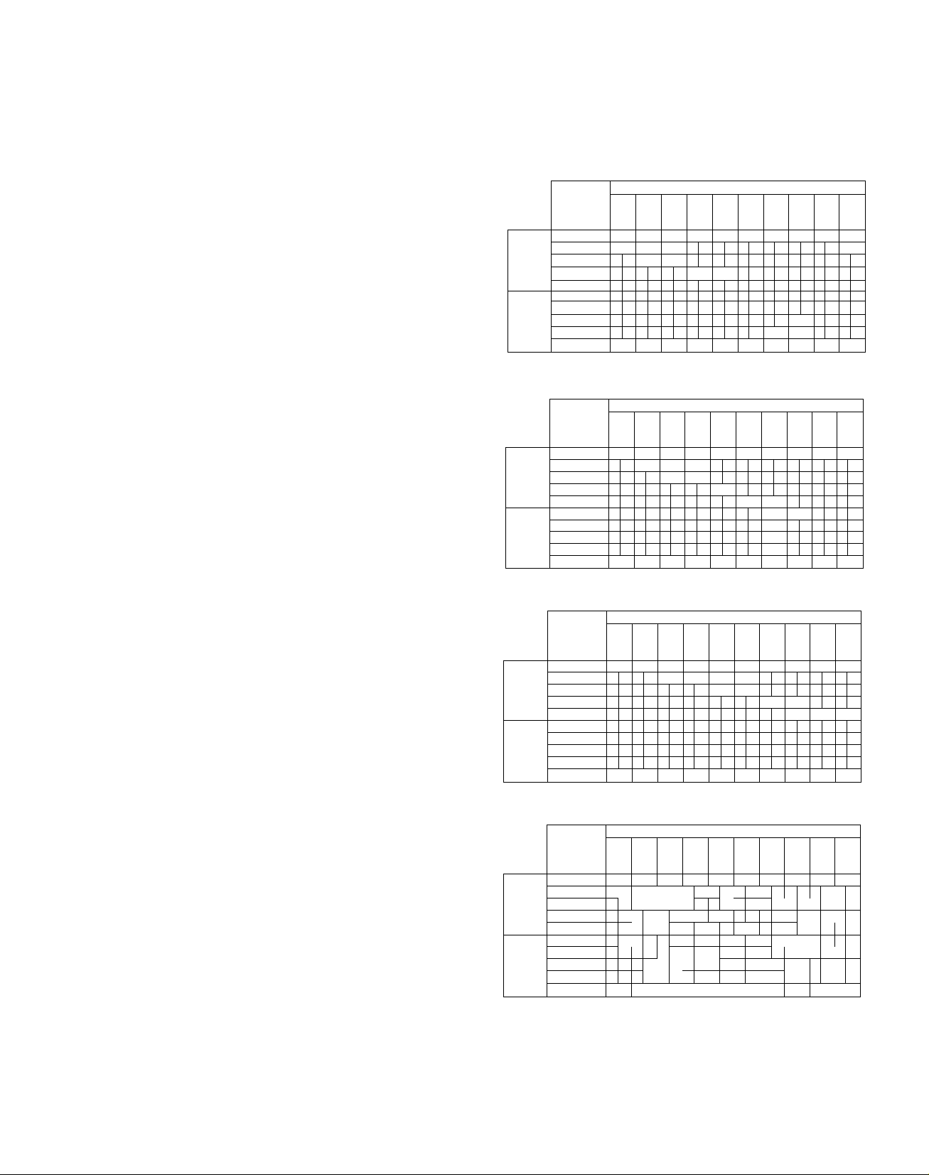
The correct liquid-tube diameter cem be determined by using
the appropriate table as described in steps 1 through 7
which follow. Be certain to use only the hquid-tube table
that matches the size unit being installed. (See Tables IV
thru VII.)
1. Measure total one-way horizontal distance for intended
tubing path.
2. Measure total one-way vertical distance for intended
tubing path.
3. At left-hand end of table, select value that matches
measured vertical length. Be sure to note that upper
section of table is used if coohng coü is above unit,
whereas lower section is used if cooUng coil is below
unit.
4. Move across this Une towards right-hand side until cor
rect vertical column is reached for measured horizontal
length.
5. Correct diameter will be indicated at intersection of
these lines.
6. If point of intersection falls within shaded area, crank
case heater must be added.
7. For apphcations where coohng coil is to be placed more
than 50 feet below unit, see your Distributor for spe
cific recommendations.
Here is an example; Unit is size 025. Coohng coil is located
43 feet above unit. Horizontal distance is 72 feet.
First, in the section marked “Coü Above Unit,” find the hne
showing measurement of 41-50 feet. Follow this line
towards the right until it intersects the vertical colunrn
marked 71-80 feet. The correct tube size is 5/16-inch OD,
and the fact that the 5/16-inch size falls in the shaded area
means that the unit wih require a crankcase heater.
B. Instructions for Total System Charge
The total system refrigerant charge includes the condensing
unit, the evaporator coü, and the interconnecting tubing.
The factory charge is sufficient for a system using 25 feet of
interconnecting tubing and a matching evaporator coil. For
systems using tubing lengths other than 25 feet, adjust the
charge in accordance with the notes under the proper table
(IV through VII).
TABLE IV—UNIT SIZE 025
Vertical
Distance to to to
(Ft) 10 20 30 40
Coil
Above 21 to 30 1/4 1/4
Unit
Coil
Below
Unit
41 to 50
31 to 40, 1/4
11 to 20 1/4 1
Oto 10
Oto 10
11 to 20
21 to 30
31 to 40 1/4
41 to 50 1/4 1/4 51«; /3«,
D 11 21 31
5/16 5/16 5/46 5/16
Horizontal Distance- -Feet
to to to
5/16 5/-16 5/16
t
t
4,/4,<
41 51
50 60 70 80 90 100
61
to to
5/16
71 81 91
to to
5/16 3/8
5/16
1/4
1
5/16
5/J6
5/16
5/16
TABLE V—UNIT SIZE 040
Horizontal Distance— Feet
Vertical a
Distance to to to to to to to to to to
(Ft)
Coil 31 to 40
Above 21 to 30 1./4
Unit 11 to 20 1/4
Coil 11 to 20
Below
Unit
41 to 50 1/4 5/16 5/16 5/16 5/16 5/16 5,'16 5/16 5/16 5/16
Oto 10 1/4
Oto 10 1/4
21 to 30 1/4
31 to 40
41 to 50 1/4 1/4 1/4 1/4 1/4 1,-4
11 21 31 41 51 61 71 81
10 20 30 40 50 60 70 80 90 100
1/4
t
t
1/4
Î
5/16
5/16
5./16
91
5/16
TABLE VI—UNIT SIZE 047
Horizontal Distance— Feet
Vertical 11 21 31
Distance to to to to to to to to to to
(Ft)
41 to 50 5/16 5/16 3/8 3/8
Coil 31 to 40 5/16 5/16
Above 21 to 30 5/16
Unit 11 to 20 5/16 5/16
Oto 10
Oto 10
Coil 11 to 20
Below 21 to 30
Unit 31 to 40
41 to 50 5/16 5/16 5/16 5/16 5/16 5/16 5/16 5/16 5/16
10 20 30 40 50 60 70 80 90 100
41
51 61 71 81 91
3/8 3/8 3/8
3/8
m/§
.t
5/16
t
5/16 5/16
5/16
TABLE VII—UNIT SIZE 054
Vertical 11 21 31 41 51 61 71 81 91
Distance to to to to to to to to to to
(Ft)
Coil 31 to 40
Above 21 to 30
Unit 11 to 20 5/ 5.'16
Coil
Below
Unit
(1) Unit charge adequate for 3/8-in. OD tube lengths up to 25 ft. For lengths
(2) Unit charge adequate for 1/4-in. OD tube lengths up to 75 ft. For lengths
(3) Unit charge adequate for 5/16-in. OD tube lengths up to 40 ft. For lengths
(4) If tube size falls within shaded area, add crankcase heater.
41 to 50
Oto 10
Oto 10
11 to 20
21 to 30
31 to 40
41 to 50 5/16
below or above 25 ft, adjust charge at rate of 0.6 oz/ft. This may be done by
using superheat charging label.
above 75 ft, adjust charge at rate of 0.2 oz/ft.
above 40 ft, adjust charge at rate of 0.4 oz/ft.
10
3/8 3/8 3/8 3/8
5/ 16
' ’
Horizontal Distance— Feet
30 40 50
20
t
5.'16] 5/ 1 6
5/16|5/16|5/16|5/16|5/16 3/8 3/8 3/8 3/8
3 5
1'
i J
70 80 90
60
3./8 3/8 3/8 3,'8 3/8
5/16
5 1 6
1
i
6
...
4
100
—3—
Page 4
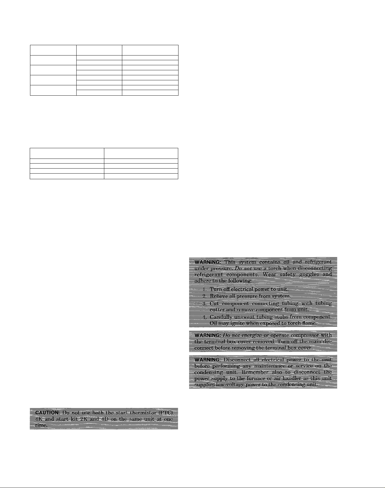
TABLE Vili—RECOMMENDED
SUCTION-TUBE DIAMETERS
Suction-Tube
Size
025 0 to 120 5/8
040 Oto 60
047
054 0 to 65 1-1/8
NOTE: The above table is based on a tube loss of 2°F. Longer lengths
can be used in each diameter listed, or smaller diameters may
be used, but the result will be larger tube losses with a lower
unit capacity and efficiency rating. Refer to your Distributor for
specific details.
Length (Feet)
120 to 150 7/8
60 to 135 7/8
Oto 85 7/8
85 to 150 1-1/8
65 to 150 1-3/8
Recommended
Diameter (inches)
3/4
TABLE IX—REQUIRED PISTON SIZE FOR
INDOOR COIL
Condensing
Unit Size
025
040 76
047
054 88
NOTE: The piston sizes listed in this table are for systems where the
vertical separations between indoor and outdoor units do not
exceed 10 feet. For vertical separations exceeding 10 feet,
consult the factory for the proper piston sizes.
Piston
identification No.
59
82
If other than matching interconnecting tubing or evapora
tor coU is being used, use an accurate scale or volumetric
charging cylinder (such as a Dial-A-Charge) and weigh in the
refrigerant until the desired superheat temperature is
obtained. See the superheat charging label attached to each
condensing unit.
When system charging has been completed, stamp the total
amount of refrigerant in the block provided on the condens
ing unit rating plate. The total system charge is the same as
the field charge.
C. Determining Suction-Tube Diameter
The correct suction-tube diameter can be determined by
using Table VIII as follows:
1. Measure total length (vertical and horizontal) of
intended tubing path.
2. Find correct unit size at left of table.
The tube lengths are shown in the center of the table
with the appropriate diameters on the right.
iX. SEQUENCE OF OPERATiON
When the thermostat “calls for cooling,” the thermostat
contacts close, energizing contactor holding coil 2D or 2M
from a 24-volt external power source. The contactor closes,
energizing compressor motor 3F or 3J and condenser fan
motor 3C or 3D with supply voltage.
When the thermostat is satisfied, the contacts open,
deenergizing contactor holding coil 2D or 2M and, in turn,
breaking the supply voltage circuit. AH motors should stop.
Optional Start Assist (When Used)
Start thermistor 4K is wired in parallel to run capacitor 4G
on single-phase units. Its purpose is to provide additional
start assist. When compressor 3J starts, start thermistor
4K builds its internal resistance to a level where it effec
tively removes itself electrically from circuit. When contac
tor 2D or 2M is deenergized, start thermistor 4K will auto
matically reset itself in approximately 3 to 5 minutes.
Start Kit 2K and 4D
The start kit consists of start relay 2K and start capacitor
4D. Start capacitor 4D helps compressor 3J start. When the
compressor starts, start relay 2K disconnects start capaci
tor 4D from the circuit, allowing compressor 3J to run on
run capacitor 4A or 4G. When contactor 2D or 2M deener
gizes, start relay 2K reconnects the start capacitor in the
circuit, making it ready for the next compressor start.
X. CARE AND MAINTENANCE
For continuing high performance, and to rnmirnize possible
equipment failure, it is essential that periodic maintenance
be performed on this equipment. Consult your local Dealer
for the proper frequency or maintenance and the availability
of a maintenance contract.
The air for the condenser coil is drawn into the unit on four
sides and discharged out the top. Keep the air inlet and out
let grilles unplugged and clear of any obstructions at all
times. Never cover the unit or lean anything against it
which might restrict airflow or cause hot air from the top
grille to recirculate into the sides. Keep trash and debris
away from the uiut at all times. Never stand on the unit or
use it as a support for ladders, etc.
The refrigerant tubing connecting this unit with the coohng
coil is easily crushed or crimped. Therefore, do not hang or
stand anything on it. Do not move the unit after it has been
installed, as this may crimp the tubing and cause the unit to
malfunction.
The ability to properly perform maintenance on this equip
ment requires certain mechanical skills and tools. If you do
not possess these, contact your Distributor for
maintenance.
The minimum maintenance that should be performed on
this equipment is as follows:
1. Check condenser coü for cleanliness each month during
cooling season. Clean as necessary, but at least once at
the beginning of each cooling season. To insure reliable
performance in sea coast or contaminated atmosphere
installations, the unit must be kept free of debris and
the condenser coil flushed with fresh water at least
once a month. See Section X, item A, for proper
procedures.
—4—
Page 5
TERMINAL
BLOCK
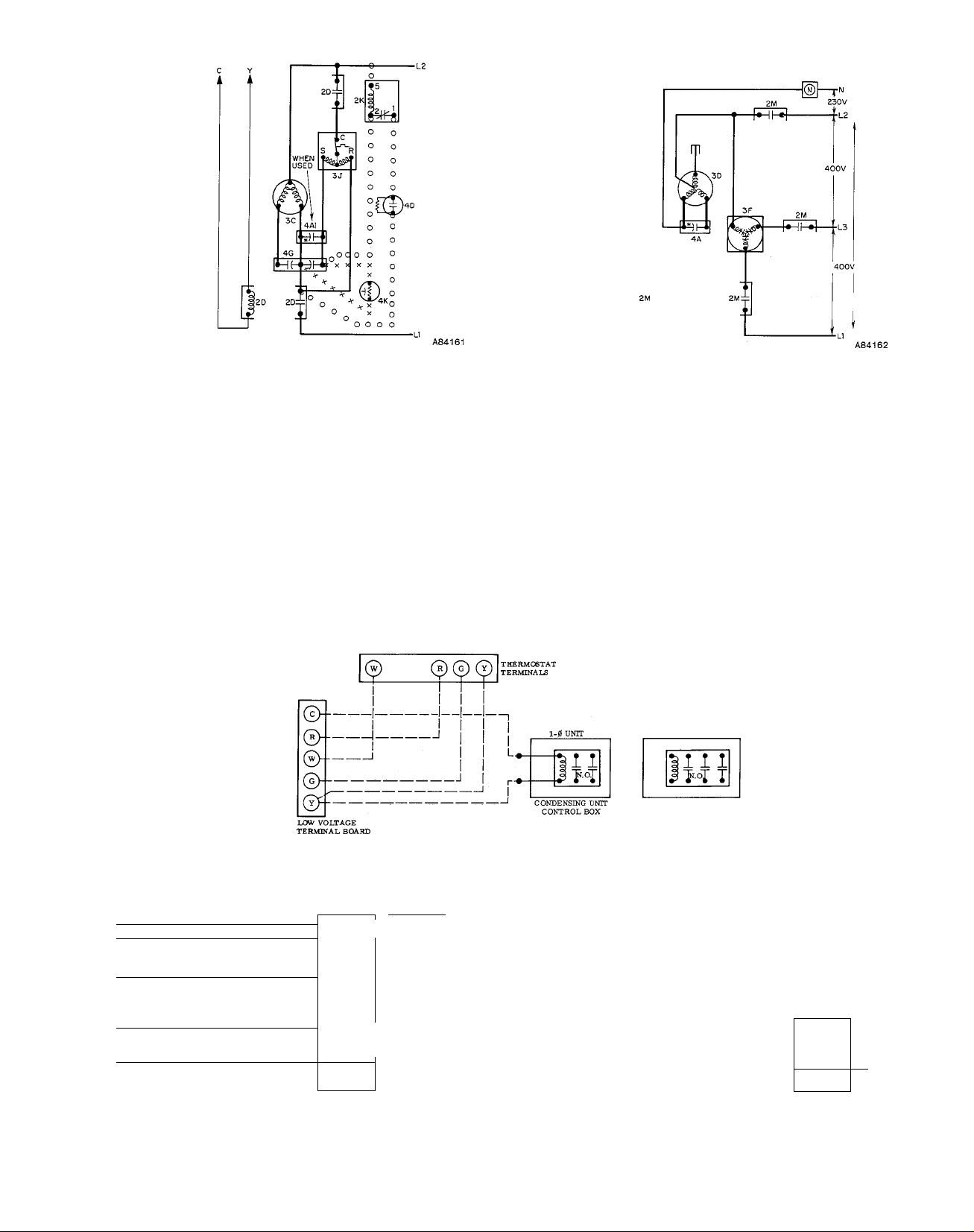
Figure 3—Typical Single-Phase Wiring
--------
FIELD LOW VOLTAGE ooo
---------
FIELD HIGH VOLTAGE
----------
FACTORY LINE VOLTAGE XXX
----------
FACTORY LOW VOLTAGE
2A-Contactor SPST
2D-Contactor DPST
2K-Start Relay (When Used)
2M-Contactor TPST (N.O.)
3C-Condenser Fan Motor
3D-Condenser Fan Motor
3J-Compressor (Single-Phase)
3F-Compressor (3-Phase)
FIELD WIRING DIAGRAMS
Figure 4—Typical Three-Phase Wiring
STARTING CIRCUIT
LINE VOLTAGE (WHEN USED)
ALTERNATE STARTING CIRCUIT
LINE VOLTAGE (WHEN USED)
LEGEND
4A1 -Run Capacitors
4D-Start Capacitor (When Used)
4G-Run Capacitor (Dual)
4K-Start Thermistor (When Used)
11 A-Crankcase Heater (When Used)
3-0 DNIT
! ! 1 ! ^
WIRE NUT ] 1
\ Ml
MLJL J
R # 1
i
Figure 6—With Fan-Coil Unit
(For cooling-only, delete W.)
LL J r-
Figure 5—Typical Field Low-Voltage Wiring
--------
FIELD LOW-VOLTAGE WIRING
--------
FIELD HIGH-VOLTAGE WIRING
--------
FACTORY LOW-VOLTAGE WIRING
FIELD-SUPPLIED
FUSED DISCONNECT
•
—-[TD*Ti--
• >
. »
r-
•HI-»-
----
-HI
•HP»-
—-^T~n^-
-----
I SINGLE
fPHASE
—5—
^
©--■
(¡>------------
LC
------
FIELD LOW-VOLTAGE WIRING
------
FIELD HIGH-VOLTAGE WIRING
------
FACTORY LOW-VOLTAGE WIRING
3
•Hh-»--
• •-
r-
•HP»-
--OZZEkf»
•HI-»-
r
/^GND
Figure 7—With Blower Package (For
cooling-only, delete W.)
-
--
—
Page 6
2.
Check fan motor and blade for cleanliness and lubrica
tion each cooling season. Clean and lubricate as
necessary.
3.
Check electrical connections for tightness and controls
for proper operation each cooling season. Service as
necessary.
A. Condenser Coil
Remember to disconnect electrical power before removing
any panels.
Since the air is drawn into the sides of the unit and dis
charged out the top, most of the dirt will collect on the out
side surface of the coil. However, some dirt will penetrate
the coil. This condition is very difficult to see without
removing the top cover.
To properly check the condenser coil for cleanliness, or to
clean the coil; proceed as follows:
1. Remove top cover. Enough motor wire is provided so
that the top cover can be lend on edge without discon
necting the motor leads. (CHp wire tie to release wire.)
2. Clean coil by spraying from inside outward with highvelocity stream of water. (Garden hose is sufficient.)
Be careful not to damage the coil fins. Be sure to wash the
dirt from the coil. Space has been provided under the coil to
flush away the dirt. Drain holes are also provided in the
base pan. Be sure they are open. If the coil is coated with oil
or grease, it can be cleaned with a mUd detergent or an ap
proved coil cleaning agent, then rinsed with clear water. Be
careful not to get water in the compressor and unit control
boxes.
B. Condenser Fan Motor and Blade
Remember to disconnect electrical power before removing
any panels.
1. Remove screws holding top cover.
2. Lift top with motor and fan blade out of hole. Do not
cut or stretch motor electrical leads. Be careful not to
bend fan blade.
3. Clean motor and blade with soft brush or rag. Be care
ful not to disturb balance weights on fan blade.
4. Check fan blade setscrew for tightness.
5. Lubricate fan motor.
a. Remove dust caps or plugs from oil holes located at
each end of motor.
b. Use teaspoon, 5cc, 3/16 oz, or 16 to 25 drops of good
grade SAE 20 nondetergent motor oil in each hole.
AUow time for total quantity to be absorbed by each
bearing.
c. Wipe excess oil from motor housing.
d. Replace dust caps or plugs in oil holes.
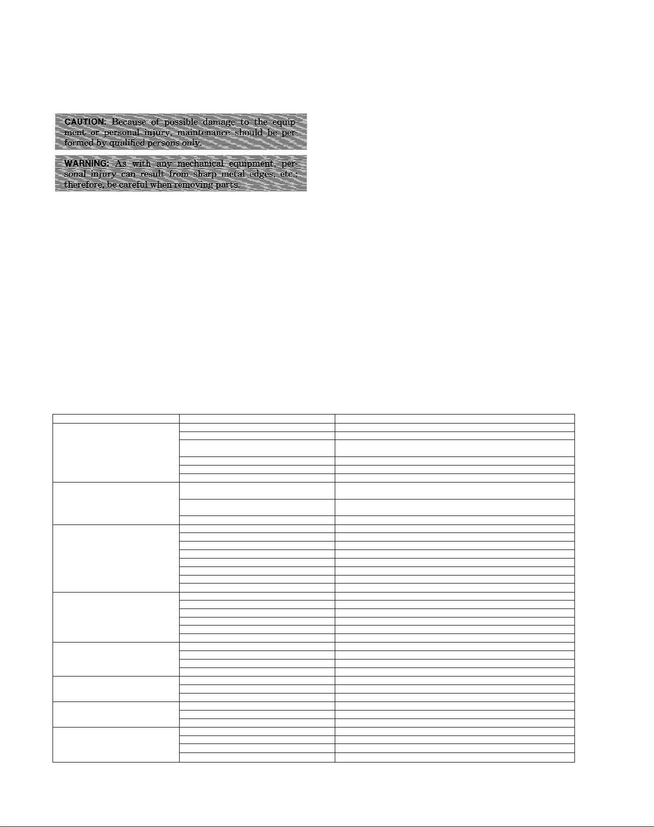
SYMPTOM CAUSE
Compressor and condenser
fan will not start
Compressor will not start,
but condenser fan runs.
Compressor cycle (other than
normally satisfying thermostat).
Compressor operates
continuously.
Excessive head pressure
Head pressure too low
Excessive suction pressure
Suction pressure too low
Power failure Call power company.
Fuse blown or circuit breaker tripped
Defective thermostat, contactor,
or control relay
Low line voltage
Incorrect or faulty wiring
Thermostat setting too high
Faulty wiring or loose connections in
compressor circuit
Compressor motor burned out, seized, or
internal overload open
Defective run capacitor Determine cause and replace.
Refrigerant over or under charged
Defective compressor Replace and determine cause.
Low line voltage Determine cause and correct.
Blocked condenser Determine cause and correct.
Defective run capacitor
Defective thermostat
Faulty condenser fan motor or capacitor Replace.
Restriction in refrigerant system
Unit undersized for load
Thermostat set too low ♦Reset thermostat.
Low refrigerant change
Leaking valves in compressor Replace compressor.
Air in system Blow refrigerant, evacuate system, and recharge.
Condenser coil dirty or restricted
Dirty condenser coil
Refrigerant overcharged Purge excess refrigerant.
Air in system Blow refrigerant, evacuate system, and recharge.
Condenser air restricted or air short-cycling Eliminate cause.
Low refrigerant charge
Compressor valves leaking Replace compressor.
Restriction in liquid tube Remove restriction.
High heat load Check for source and eliminate.
Compressor valves leaking
Refrigerant overcharged Purge excess refrigerant.
Low refrigerant charge
Metering device or low side restricted
Low evaporator air Increase air.
Temperature too low in conditioned area ♦Reset thermostat.
♦Thermostat should be set between 72° and78°F.
TABLE X—TROUBLE ANALYSIS CHART
REMEDY
Replace fuse or reset circuit breaker.
Replace component.
Determine cause and correct.
Check wiring diagram and rewire correctly.
♦Lower thermostat setting below room temperature.
Check wiring and repair or replace.
Replace compressor and determine cause.
Blow refrigerant, evacuate system, and recharge.
Determine cause and replace.
Replace thermostat.
Locate restriction and remove.
Decrease load or increase unit size.
Locate leak; repair and recharge.
Clean coil or remove restriction.
Clean coil.
Check for leaks; repair and recharge.
Replace compressor.
Check for leaks: repair and recharge.
Remove source of restriction.
—6—
Page 7
6. To reassemble unit:
a. Reinstall top cover with fan motor and blade.
b. Push excess motor leads back into wire retainer and
replace all screws.
c. Reconnect electrical power and check fan for proper
operation.
C. Electrical Controls and Wiring
With power disconnected to unit, check all electrical connec
tions for tightness. Tighten aU screws on electrical connec
tions. If any smoky or burned connections are noticed, dis
assemble the connection, clean aU parts and stripped wire,
Standard Installation Practices
reassemble properly, (Use new connector if old one is burned
or corroded.) and secure tightly. Electrical controls are diffi
cult to check without proper instrumentation; therefore,
reconnect the electrical power to the unit and observe the
unit through one complete operating cycle.
If there are any discrepancies in the operating cycle, contact
your Distributor and request service.
D. Refrigerant Circuit
The refrigerant circuit is difficult to check for leaks without
proper equipment. Therefore, if low cooling performance is
suspected, contact your local Distributor for service.
This Standard Installation Practices publication is intended
for use with all electric air conditioning units ranging from
14,000 thru 60,000 Btuh.
Modern air conditioning systems consist of a remotely
located condensing unit, an evaporator coU, and intercon
necting refrigerant tubes. The proper installation of each of
these components wUl insure that the system wiU provide
the comfort for which it is designed. The following pages list
the minimum steps to be taken during the installation of an
air conditioning unit.
In general, the condensing unit should be located remotely
from the evaporator coil and have adequate clearances for
airflow and service. The evaporator coil should be located in
an air handler that has enough capacity to load the coil and,
the refrigerant tubes should be as short as practical.
Extreme care should be taken when installing the system to
avoid contaminating it with edr and moisture: Either con
taminant will cause a system failure.
When the system is placed in operation, it is important that
the homeowner be informed of the maintenance steps
required to keep the system in proper operation. Among
these are the following:
1. Keep air filter in place when system is in operation;
replace or clean it regularly.
2. Keep condenser coü clean, and do not obstruct airflow.
3. If system has crankcase heater, turn on power to unit
at least 12 hours before thermostat is turned to cooling
for spring startup.
4. It is not recommended that condensing unit be oper
ated below 55° F outdoor temperature. If operation
below this temperature is desired, an optional lowambient kit is available from your Distributor.
The following sections, when used in conjunction with the
detedled unit instructions, Eire the steps needed to complete
the installation of an air conditioning system. If more
detailed instructions are required, see your Distributor.
I. LOCATING THE UNIT
This condensing unit is approved for outdoor installations.
1. Consult local codes or ordinances for restrictions
regarding location of unit.
2. Consult dimensional drawing for following:
a. Location of refrigerant connections and electrical
connections.
b. Recommended clearEmces.
c. Direction of condenser airflow.
d. Mounting base dimensions.
3. Place unit on level base strong enough to support
weight of unit and to resist effects of frost heaving, etc.
Concrete lintels can be used if spaced to adequately
support unit.
4. AUow air to circulate under unit. Legs or bases are pro
vided on most units for this purpose. If legs or bases
are not provided, spacers can be obtained from your
Distributor—or unit may be set on a bituminous mix
ture, such as roofing tar, to prevent base pan from rust
ing. Do not plug drain holes.
5. On rooftop applications, locate unit at least 6 inches
above roof surface. Where possible, place unit above a
load-bearing wall. Arrange supporting members to ade
quately support unit and minimize transmission of
vibration to building. Either precast concrete lintels,
concrete blocks, treated timbers, or steel beams can be
used. Consult local codes governing rooftop appli
cations.
6. Avoid locations where flowers, shrubs, etc. are in path
way of condenser discharge air, or where condenser f£m
wiU discharge against prevailing wind or building.
Select a location for the unit where ice and snow wiE
not faE from an overhang and damage the unit top or
fan blade.
7. Avoid locations where normal operating sounds may be
objectionable, such as beneath windows, between struc
tures, or near patios. Should operating sounds be objec-
-7—
Page 8
tionable, consideration should be given to a shielding
barrier. Consult your Distributor or the current pubhcation of ARI Standard 270 for assistance in determin
ing a suitable location with minimum of operating
sounds.
8. Keep distance between evaporator coil and condensing
unit as short as possible.
9. Consult your Distributor regarchng roof-mounted con
densing units on multilevel buildings.
OPENING AND CLOSING OF VALVES
1. Use correct tool.
2. Remove valve stem cap.
3. Front-seat—turn clockwise until valve stem bottoms.
Do not overtighten.
4. Open—turn counterclockwise until stem just contacts
snapring in valve body. Do not overtighten.
5. Replace valve stem cap and be sure that it is tight.
II. INSTALLING REFRIGERANT TUBES
IMPORTANT: The condensing unit is charged at the fac
tory. Be sure both service valves are front seated (turned
clockwise) to avoid loss of the charge. DO NOT REMOVE
REFRIGERANT TUBE CONNECTION SEALS FROM
THE CONDENSING UNIT, THE MATCHING EVAPO
RATOR COIL, OR THE REFRIGERANT TUBING,
UNTIL READY TO MAKE THE ACTUAL CONNEC
TION AT THE POINT OF SEAL.
If either refrigerant tubing or evaporator coil is exposed to
atmospheric conditions for longer than 5 minutes, they
must be purged. See Section IV, “Purging,” for the proper
method.
If other than matched refrigerant tubing is used, select an
approved (type-L) refrigerant tubing of the correct size. (DO
NOT USE WATER TUBING.) Flare this tubing, using a stand
ard 45-degree SAE flaring tool. Insulate the suction tube
with an insulation having an adequate vapor barrier (e.g.
Armaflex or Ensolex). It wiU be necessary to evacuate this
tubing and evaporator cod. See Section V, “Evacuation,”
for proper method.
NOTE: All refrigerant tube joints erected on the premises
should be exposed to view for visual inspection and leak
testing before being covered or enclosed.
When a complete system (condensing unit, refrigerant tub
ing, and evaporator cofl.) is used, a filter-drier is not required
in the system. However, if other than matched refrigerant
tubing or coils are used, or if the refrigerant tubing or coil is
exposed to atmospheric conditions for longer than 10 min
utes; a filter-drier must be installed in the system at the coil.
(An appropriate size of filter-drier is available from your
Distributor.)
NOTE; Additional refrigerant must be added to the system
and compensate for the additional volume of the filter-drier,
and different tubing lengths.
Install refrigerant tubes as follows:
1. Consult local codes or ordinances before running refrig
erant tubes.
2. Install evaporator coil in accordemce with instructions
packaged with coil.
3. If evaporator coil requires thermal expansion valve,
obtain proper valve from your Distributor and install
in accordance with instructions packaged with evapo
rator coil.
4. Run refrigerant tubes as directly as possible, avoiding
unnecessary turns and bends.
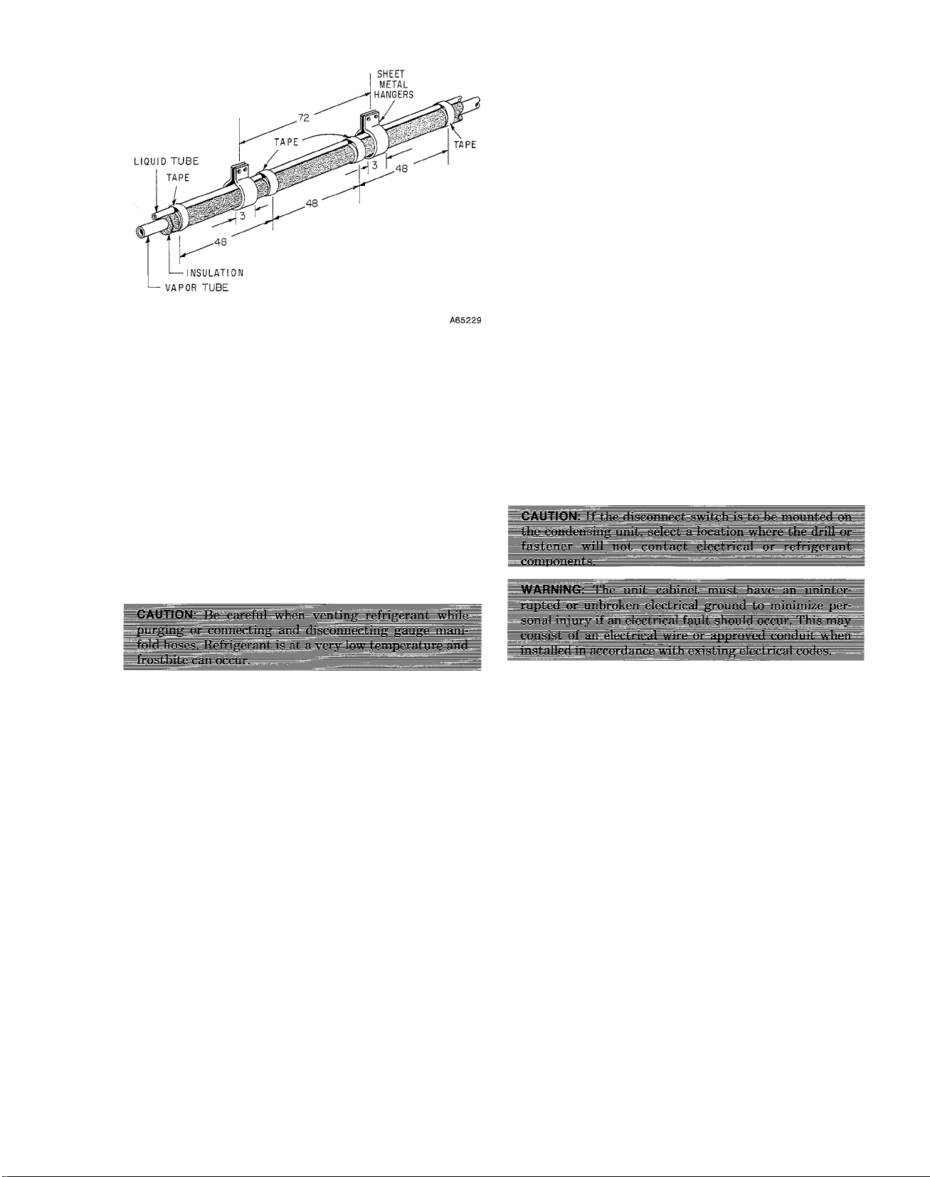
5. Tape liquid tube to top of insulated suction tube for
support. See Figure 3.
6. Suspend refrigerant tubes so they do not damage insu
lation on suction tube and do not transmit vibration to
structure. See Figure 3. Also, when passing refrigerant
tubes through wall, seal opening so vibration is not
transmitted to structure. Leave some slack in refriger
ant tubes between structure and unit to absorb
vibration.
7. If refrigerant tubes are too long, they should be rolled
into loop and placed in horizontal plane with end leav
ing loop going to compressor, coming out of bottom. If
desired, excess may be cut off and tubing braised.
8. Be sure both service valves are front seated (turned
clockwise). It is necessary to remove valve stem caps to
check.
9. When required, connect filter-drier (available from your
Distributor) in hquid tube at evaporator coil.
NOTE: The flow directional arrow, located on the label of the
filter-drier, must point toward the evaporator coil.
10. Connect tubing to condensing unit and evaporator coil,
as shown in Figure 2. DO NOT REMOVE SEALS
UNTIL READY TO MAKE THE ACTUAL CON
NECTIONS AT POINT WHERE SEAL IS
REMOVED.
11. Refrigerant tubing and evaporator coil is now ready for
leak testing.
III. LEAK TESTING
No installation is complete until the entire system has been
checked for leaks. This check should include aU field and fac
tory joints. To check a system for leaks, proceed as follows:
1. Remove valve stem caps from both service valves and
check to be sure valves are front seated (turned clock
wise). Remove gauge port caps.
2. Attach gauge manifold to ports on service valves.
Hoses of gauge manifold must have valve core
depressors.
3. Pressurize evaporator coil and interconnecting refriger
ant tubing with vapor from an external refrigerant cyl
inder of R-22 until system and cyUnder pressures are
equalized.
NOTE: NEVER USE A UNIT CHARGE FOR LEAK
TESTING.
4. Leak-test with electronic detector, halide torch, or
hquid-soap solution.
5. Release pressure and repair any leaks found. Repeat
leak test as necessary.
When system is free of leaks, proceed as follows:
If system is to be purged, leave service valves in
a.
front-seat position. Leave gauge manifold attached
to system and proceed to Section IV.
If system is to be evacuated, leave service valves in
b.
front-seat position. Remove refrigerant cylinder
from gauge manifold and proceed to Section V.
If system is to be started and the checking charge
c.
procedure is to follow, open (counterclockwise) both
service valves. Then proceed to step 3, Section VII.
If system is to be left in the leak-tested condition,
d.
open (Turn counterclockwise.) both service valves
—8—
Page 9
and remove gauge manifold. Replace caps on gauge
ports and valve stems. Be sure they are tight!
IV. PURGING
If either the refrigerant tubing kit or the evaporator coil is
exposed to atmospheric conditions during installation for
longer than 5 minutes, the refrigerant tubing and the evapo
rator con must be purged.
NOTE: DO NOT USE THE UNIT CHARGE TO PURGE
THE REFRIGERANT TUBING. To purge the refrigerant
tubing and the evaporator coil, proceed as follows:
1. Disconnect hose from low side of gauge manifold.
2. Open valves on R-22 refrigerant cylinder and high side
of gauge manifold. Allow approximately 1/2 to 1 pound
of refrigerant vapor to flow through system and out
hose attached to gauge port on suction service valve.
1. Connect evacuation equipment to system through
gauge manifold.
2. Evacuate system, following appropriate steps for type
of evacuation equipment used.
3. Pressurize system with refrigerant to 10 psig and open
(Turn counterclockwise.) both service valves.
4. Remove gauge manifold. Replace valve stem and gauge
port caps on both service valves (Be sure they are
tight.) if system is to be left in evacuated condition. It
wfll not be necessary to remove gauge manifold if
checking-charge procedure is to follow.
VI. ELECTRICAL CONNECTIONS
IMPORTANT: Before proceeding with the electrical con
nections, make certain that the volts, hertz, and phase cor
respond to that specified on the unit rating plate. Also,
check to be sure that the service provided by the utility is
sufiicient to handle the additional load imposed by this
equipment. Refer to the Ratings and Performance table in
the detailed unit instruction and unit rating plate for equip
ment electrical requirements.
The attached wiring diagrams show the proper field highand low-voltage wiring. Make all electrical connections in
accordance with the National Electrical Code and any local
codes or ordinances that might apply.
Use a separate branch electrical circuit for this unit. A dis
connecting means must be located within sight of, and
readily accessible to, the unit.
3. Pressurize system with refrigerant to 10 psig and close
valves on refrigerant cylinder and gauge manifold.
Reattach hose to low side of gauge manifold.
4. Open (Turn counterclockwise.) both service valves.
Remove gauge manifold from gauge ports of service
valves and replace valve stem and gauge port caps (Be
sure they are tight.) if system is to be left in the purged
condition, it wiU not be necessary to remove gauge
manifold if checking charge procedure is to follow.
V. EVACUATION
It is extremely important to have an installation in which
aU refrigerant tubes and system components are completely
free of air and moisture. If, during the installation, the
refrigerant tubing kit or the evaporator coil becomes con
taminated with moisture or liquid water, or other than
matching components are used; the refrigerant tubes and
evaporator coü must be evacuated.
If the installer can pull the system down to a reading of
1000 microns or less with his deep vacuum equipment, he
can consider the system free of air and moisture when this
level is reached.
If, however, the installer has an evacuation pump (one
which will only pull a vacuum of approximately 28 inches)
rather than a deep vacuum pump, he must triple-evacuate
the system with the required number of purges and holding
periods. The initial preparation for evacuation of the refrig
erant tubing and evaporator coil is as follows:
NOTE: We require the use of copper wire between the dis
connect switch and the unit. Whenever aluminum wire is
used in the branch circuit wiring with this unit, adhere to
the following recommendations: Connections must be made
in accordance with the National Electrical Code, using con
nectors approved for aluminum wire. The connectors must
be UL approved (marked Al/Cu with the UL symbol) for the
application and wire size. In preparing the wire, just before
installing the connector, all aluminum wire must be “brushscratched” and coated with a corrosion inhibiter such as
Pentrox A. When it is suspected that the connection wfll be
exposed to moisture, it is very important to cover the entire
connection completely to prevent an electrochemical action
that will cause the connection to fail very quickly. Do not
reduce the effective size of wire, such as cutting off strands
so that the wire wfll fit a connector. Proper size connectors
should be used.
If aluminum conductors are to be used, the wire size
selected must have a current capacity not less than that of
the copper wire specified, and must not create a voltage
drop between the service panel and the unit in excess of 2%
of the unit rated voltage.
Check all electrical connections (both factory and field) for
tightness. This should also be done after the unit has
reached operating temperatures, especially if aluminum con
ductors are used.
MR. ELECTRICIAN, PLEASE NOTE: DO NOT
ATTEMPT TO OPERATE THIS CONDENSING UNIT
—9—
Page 10
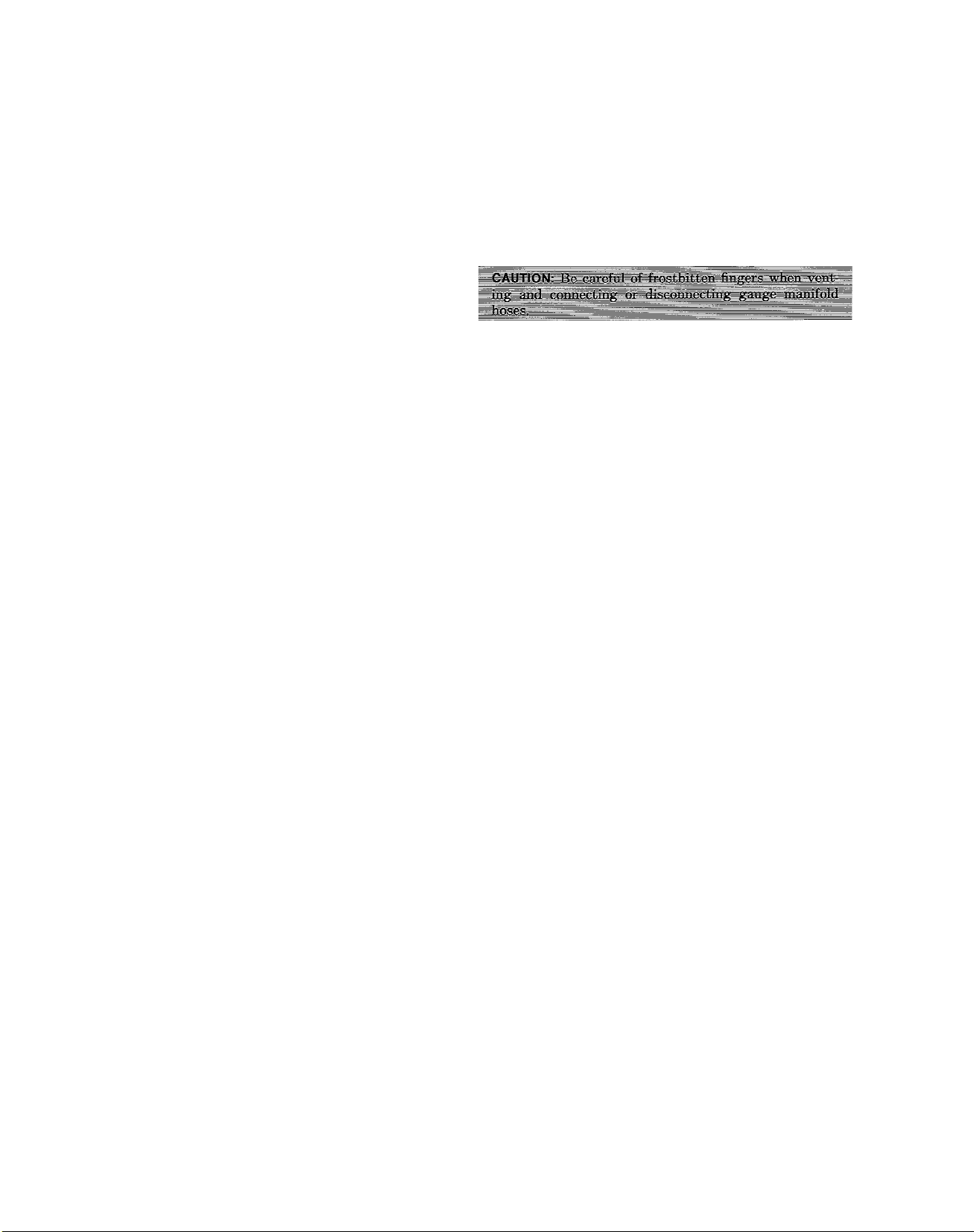
UNTIL ALL REFRIGERANT CONNECTIONS HAVE
BEEN MADE AND BOTH SERVICE VALVES HAVE
BEEN CHECKED FOR THE OPEN POSITION.
(TURNED COUNTERCLOCKWISE.) IT IS NECESSARY
TO REMOVE THE VALVE STEM CAPS TO CHECK.
The single-phase compressor motor used in this condensing
unit may be a permanent-spht-capacitor-tj^e (PSC) motor,
designed to start under low-load conditions only; therefore,
make sure that the system pressures have equahzed before
attempting to start the unit: this takes approximately 3
minutes. Do not short-cycle the unit with the thermostat or
disconnect, as this will cause the compressor to tripout on
overload. For starting under most load conditions, an
optional starting kit is available from your Distributor.
VII. CHECKING CHARGE
No installation is complete until the operating charge level
of the unit is checked. The level of refrigerant operating
charge will determine how efficiently and economically the
unit wiU operate. An overcharged or undercharged unit wiU
lead to insufficient cooling, high operating costs, and the
possibihty of a compressor failure. To check the refrigerant
charge level, proceed as follows:
1. Remove valve stem caps from both service valves and
check valve stems for open position (counterclockwise).
2. Remove gauge port cap from both service valves and
attach gauge manifold. Purge gauge manifold and
hoses.
3. Start unit and allow it to run until operating conditions
stabihze and pressures level out.
4. Evaluate system performance and refrigerant charge
level by determining following information:
a. Low-side pressure gauge reading.
b. Dry-bulb temperature of inlet air at condenser coil.
c. Wet-bulb temperature of inlet air at evaporator coil.
This may be read at central return-air grille.
d. Liquid- or suction-tube temperature at respective
service valve.
NOTE: Use an accurate superheat, thermocouple, or
thermistor-type thermometer.
e. Compare these readings to those fisted on Unit
Charging Label located on unit. Add or remove
refrigerant as required.
NOTE: The suction-tube connection of the compressor must
be as cool as the suction tube, and the compressor base
should be warm.
5. When correct refrigerant charge level is obtained,
remove gauge manifold.
6. Replace valve stem and gauge port caps. (Be sure they
are tight.)
NOTE: Where applicable, stamp the total number pounds of
refrigerant charge onto the rating plate in the space
provided.
VIII. ADJUSTING CHARGE
If, after checking the operating charge level, the unit is
found to be undercharged or overcharged, refrigerant may
be added or removed through the gauge manifold and the
suction service valve.
To add refrigerant to a unit, proceed as follows:
1. Connect clean, dry cylinder of R-22 to center port con
nection of gauge manifold. Purge hose and connect
gauge manifold to service valves.
2. With refrigerant cylinder in upright position, open
valve on cylinder and slowly open valve on low-pres
sure gauge of manifold. Add refrigerant in vapor form
until proper amount has been added.
3. When correct refrigerant charge level is obtained, close
valves on refrigerant cylinder and gauge manifold.
4. Remove gauge manifold from service valves. Replace
valve stem and gauge port caps. (Be sure they are
tight.)
To remove refrigerant from a unit, proceed as follows:
1. Slowly open valve on low-pressure gauge side of mani
fold and vent refrigerant (slowly) through center port
connection of gauge manifold.
2. When desired amount of refrigerant has been removed
to obtain correct refrigerant charge level, close valve on
low-pressure gauge side of manifold.
3. Remove gauge manifold from both service valves.
Replace both valve stem and gauge port caps. (Be sure
they are tight.)
CHECKOUT LIST
WITH ELECTRIC POWER OFF:
1. Check all electrical wiring (both factory and field) for
completeness and tighten all electrical connections
(contactor, capacitors, relays, etc.).
2. Check condenser fan blade for proper insertion depth in
orifice plate.
3. Check evaporator blower puUey and motor pulley (beltdrive units only) for proper belt alignment and tight
ness. (Should have 1 in. of sag with normeil finger
pressure.)
4. Tighten all setscrews (evaporator blower, blower pul
ley, motor sheave, and condenser fan blade).
5. Check condenser airflow for obstructions.
6. Clean or replace air filters. Do not operate system with
out air filters in place.
7. Leak-test all refrigerant connections (fittings, joints,
gaskets, flanges, etc.)—both factory and field—with a
halide torch or electronic leak detector.
8. Replace all caps on service valves. Be sure they are
tight.
9. Check to be sure all tools and loose parts have been
removed from unit.
10. Check to be sure all panels, covers, and screws are in
place.
11. Following initial inspection, start unit and:
a. Check condenser fan and evaporator blower for
proper rotation.
b. Adjust furnace or evaporator blower for proper air
flow (approximately 400 cfm/ton).
c. Check fine and low voltage. (Should be within oper
ating voltage range stamped on unit rating plate.)
d. Check unit for proper operating refrigerant charge.
(See unit head pressure charging chart.)
e. Check compressor current draw in eunps.
f. Check unit for excessive noise, refrigerant tubing
for excessive vibration and for contact with other
parts. Correct as necessary.
g. Do not leave installation until unit has been
observed through one or two complete cycles. Make
-10-
Page 11
certain at this time ail components are operating in
correct sequence.
12. Thoroughly explain to owner(s):
a. Operation of air conditioning system (thermostat,
reset controls, etc.).
b. Care and maintenance instructions (cleaning air fil
ters, condenser and evaporator coils, blower wheel.
and lubrication of all motors and blower bearings).
c. Factory and dealer warranties and how to obtain
service, if necessary.
d. Leave copy of Owner’s Manual with customer after
you have completed necessary information in
Owner’s Manual.
—11 —
Page 12
38GP-C12SI-CIC
Supersedes 38GP-C10SI-CIC
Carrier
International
Corporation ■ number one
Manufacturer reserves the right to discontinue, or change at any time, specifications or designs without notice and without incurring obligation.
Printed in U.S.A.
air conditioninq
maker
10/86 003-811
a
 Loading...