

Page 1
HEATING & COOUNG
38GNA
Air Conditioning Unit
instaliation and Start-up instructions
NOTE: Read the entire instruction manual before starting the
installation.
SAFETY CONSIDERATIONS
Improper installation, adjustment, alteration, service, maintenance,
or use can cause explosion, fire, electrical shock or other condi
tions which may cause personal injury or property damage.
Consult a qualified installer, service agency, or your distributor or
branch for information or assistance. The qualified installer or
agency must use factory-authorized kits or accessories when
modifying this product. Refer to the individual instructions pack
aged with the kits or accessories when installing.
Follow all safety codes. Wear safety glasses and work gloves. Use
quenching cloth for brazing operations. Have fire extinguisher
available. Read these instructions thoroughly and follow all
warnings or cautions attached to the unit. Consult local building
codes and National Electrical Code (NEC) for special require
ments.
It is important to recognize safety information. This is the safetyalert symbol /îy . When you see this symbol on the unit and in
instructions or manuals, be alert to the potential for personal
injury.
Understand the signal word DANGER, WARNING, or CAU
TION. These words are used with the safety-alert symbol. DAN
GER identifies the most serious hazards which will result in severe
personal injury or death. WARNING signifies hazards that could
result in personal injury or death. CAUTION is used to identify
unsafe practices which would result in minor personal injury or
product and property damage.
The 024 size is equipped with a time-delay device which prevents
restart within 5 minutes of power interruption.
Compressor motor is equipped with an internal protector. Exces
sive current or temperature causes protector to open which gives
indication of an open circuit in motor winding. Sufficient time
should be allowed for overload to reset before assuming compres
sor has an open winding.
Compressor motor is designed to start under low-load conditions
only. Make sure system pressures have equalized before attempt
ing to start unit. Equalization takes approximately 3 minutes.
Owner should be informed not to short-cycle unit with thermostat
as this causes compressor to trip out on overload.
Each unit is shipped with refrigerant charge adequate for use with
matching coils and refrigerant tubing kits. Charge is adequate for
systems using 25 ft of interconnecting tubing. See unit rating plate
for charge quantity. See Refrigerant Charging section and Table 2
for adjustment requirements.
A WARNING
Relieve all pressure before refrigerant system repair or final
unit disposal to avoid personal injury or death. Use all service
ports and open all flow control devices, including solenoid
valves.
A CAUTION
Do not vent refrigerant to atmosphere. Recover during system
repair or final unit disposal.
A WARNING
Before installing or servicing system, always turn off main
power to system. There may be more than 1 disconnect
switch. Turn off accessory heater power if applicable. Elec
trical shock can cause personal injury or death.
Intake and discharge are on front of the unit. A minimum service
access distance of 30 in. behind unit must be provided.
NOTE: Refer to unit rating plate for ratings. '
This condensing unit is designed for use with evaporator coils or
fan coils equipped with capillary tube or piston-type refrigerant
control device. It may also be used with evaporators which have
expansion valves that equalize pressure during the off cycle or
hard shut-off expansion valves. The 018 size with hard shut-off
expansion valve requires a hard start kit.
BEFORE INSTALLATION
Check power supply: voltage, frequency and phase must corre
spond with data on unit rating plate. Power supply must be able to
handle the additional load imposed by this equipment.
The 38GNA does not have a transformer. Therefore, the furnace
transformer (or another source) must be used as a low-voltage
supply. Transformer must have an additional capacity of 15 va
above the requirement of furnace or air handler.
Manufacturer reserves the right to discontinue, or change at any time, specifications or designs without notice and without incurring obiigations.
Book] 1 I 4 PC 101 Catalog No. 563-712 Printed in U.S.A. Form 38GNA-2SI Pg 1 11-92 Replaces: 38GNA-1 SI
Tab |3a|2a
GENERAL
NOTE: Check indoor coil piston to see if it matches the required
piston shown on unit rating plate. If it does not match, replace
indoor coil piston with piston shipped with this unit. The piston
shipped with outdoor unit is correct for any approved indoor coil
combination.
Table 1—Installation Data (In.)
38GNA
Through-the-Wall
Clearance Dim.
Air Clearance
Concrete Mounting
Pad Dim.
Service Clearance*
’Unit is serviced through rear access panel. Therefore, unit can be installed
with 0-in. end clearance.
Sides
Back
018 024
26-1/2 X 29
36
27 X 17 X 5
0
30
INSTALLATION
Install condensing unit either through-the-wall, outdoors on a slab
or on the roof. When installing, allow sufficient space for airflow
clearance, wiring, refrigerant piping and servicing. Consult local
building codes and National Electrical Code (NEC) for special
installation requirements. See Fig. 1, 2 and 3 and Table 1 for
detailed installation data.
Page 2
AIR OUT
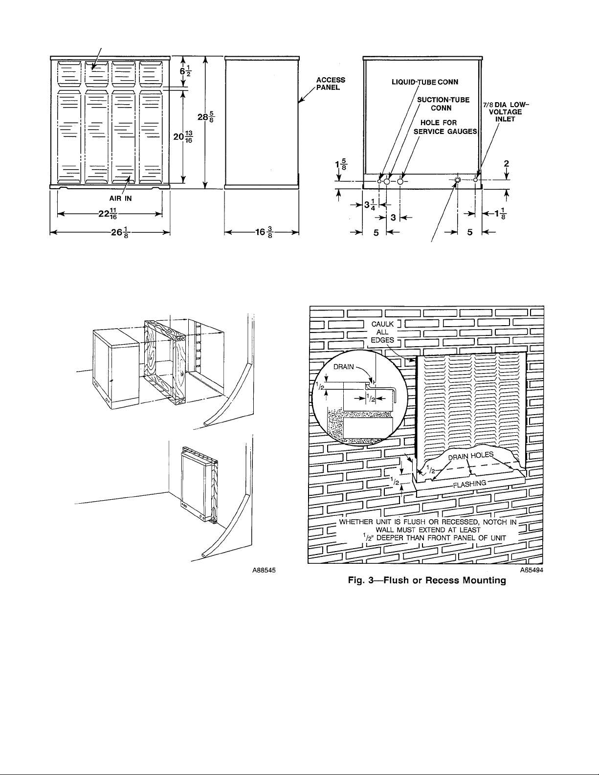
Fig. 1—Dimensions and Connections
7/8 DIA HOLE & 1-3/32 DIA K.O.
POWER INLET
A75135
Fig. 2—Roughing-ln Supporting Frame
Step 1—Make Opening in Wall
Make an opening approximately 26-1/2 x 29 in. in a wall as close
to the cooling unit as possible. Build a frame to support the
condensing unit. (See Fig. 2.)
1. Insert condensing unit with frame into the wall opening.
2. Extend unit approximately 1 in. beyond outside (finished) wall
and tilt to the outside to allow rainwater to drain off. (See Fig.
3.)
3. Fasten unit to frame with metal straps.
4. Use flashing under unit and caulk all edges to provide
weathertight seal. (See Fig. 3.)
(M>
Step 2—Make Piping Connections
SELECT CORRECT LIQUID AND SUCTION LINE
LENGTHS/DIAMETERS - Refer to Table 2.
INSTALL REFRIGERANT LINES — The condensing unit is
fully charged at the factory. Be sure both service valves are front
seated (turned clockwise) to avoid loss of charge. Do not remove
refrigerant line connection seals from condensing unit, matching
coil, or refrigerant tubing until ready to make actual connection at
point of seal.
Page 3
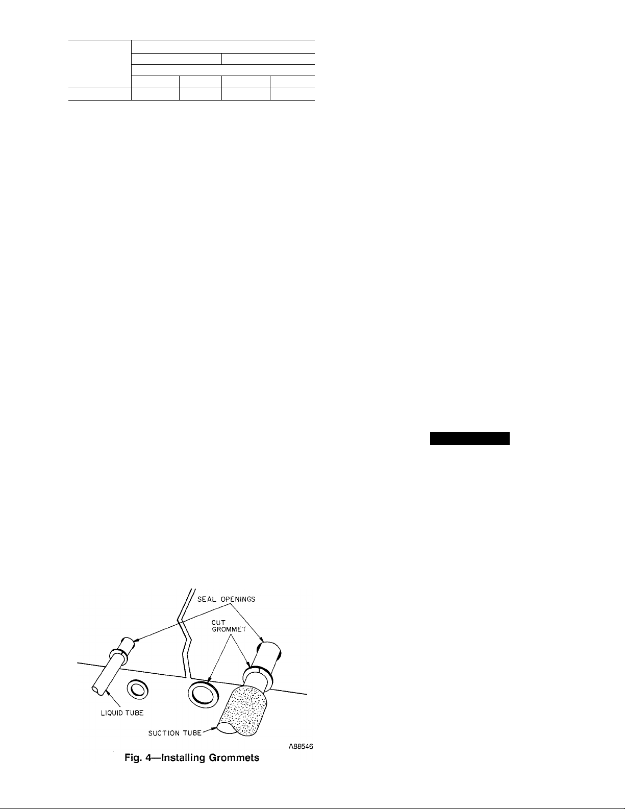
Table 2—Tubing Data
REFRIGERANT LINE LENGTH
UNIT SIZE
018, 024
1. Maximum vertical separation for evaporator over condensing unit is 50 ft.
2. Over 50 ft of vertical separation, the condensing unit must be located above
the evaporator. For requirements beyond 50 ft, obtain information from
distributor or consult Long-Line Application Guideline.
3. Charge adjustment is required when using more than 25 ft of tubing. See
Refrigerant Charging information on unit rating plate.
4. Do not use larger than 3/4-in. suction line.
10 to 50 ft
Suction
5/8 3/8
Diameter (In.)
Liquid Suction
If accessory tubing package or evaporator coil has been open for
more than 5 minutes, evacuate evaporator coil and tubing system.
Always evacuate if field-supplied tubing is used. See Evacuation
section.
Ensure field-supplied tubing is of refrigerant grade. Insulate the
suction line with insulation that has an adequate vapor barrier.
Evacuate tubing.
1. Run refrigerant lines as directly as possible, avoiding any
unnecessary turns and bends.
2. Tape the liquid line to the top of the insulated suction line for
support.
3. Suspend the refrigerant lines so they do not damage the
insulation on the suction line and do not transmit vibration to
the structure.
4. If the refrigerant lines are too long, the excess may be cut off.
5. Connect tubing to the condensing unit. The refrigerant tubing
and evaporator coil should be leak tested upon completion.
When making piping connections, be sure to provide clearance at
unit for electrical connection.
Connect suction and liquid refrigerant lines to condensing unit.
(See Fig. 1.) Make suction line connection first.
Two grommets are provided to seal the gap between refrigerant
lines and unit casing. Cut small grommet, slip it over liquid line
and push it into casing opening. Gap around suction line is sealed
in same manner except that suction line insulation must be cut and
pushed back before grommet can be slipped into place. (See Fig.
4.)
FIELD TUBING CONNECTIONS - All models are equipped
with 3/8-in. liquid and 5/8-in. suction back seated service valves
with mechanical flare field connections. Factory-supplied 3/8-in.
to 3/8- in. and 5/8-in. to 5/8-in. flare-to-sweat adaptor tubes are
provided. Field-supplied couplings are required for tubing pack
ages exceeding 50-ft long-line applications.
51 to 100 ft
3/4
Liquid
3/8
Step 3—^Test Unit
LEAK TESTING — No installation is complete until all field and
factory joints have been checked for leaks.
1. Remove valve stem caps from both service valves and check
to be sure valves are front seated (turned clockwise). Remove
service port caps.
2. Attach gage manifold to service ports of service valves and
purge hoses.
3. Pressurize evaporator coil and interconnecting refrigerant
tubing with vapor from an external refrigerant cylinder of
R-22 until the system and cylinder pressure are equalized.
NOTE: NEVER USE A UNIT CHARGE FOR LEAK TEST
ING.
4. Leak test with an electronic detector, a halide torch, or a liquid
soap solution.
5. Recover refrigerant and repair any leaks.
6. If system is free of leaks, prepare unit for operation.
EVACUATION
1. Connect evacuation equipment to system gage manifold.
2. Evacuate system following appropriate steps for type of
evacuation equipment used.
3. Pressurize system with refrigerant to 10 psig and open (turn
counter-clockwise) both service valves.
4. Remove gage manifold. Replace valve stem and service port
caps on both service valves.
Step 4—Make Electrical Connection
Field wiring must comply with local and national fire, safety and
electrical codes. Voltage to unit must be within range of 253v to
187v. Refer to nameplate for other electrical data. Contact local
power company for correction of improper line voltage.
A WARNING
According to NEC, ANSI/NFPA 70, and local codes, the
cabinet must have an uninterrupted or unbroken ground, to
minimize personal injury if an electrical fault should occur.
The ground may consist of electrical wire or metal conduit
when installed in accordance with existing electrical codes.
Failure to follow this warning could result in an electric
shock, fire, or death.
See unit’s rating plate for recommended fuse size. When making
electrical connections, provide clearance at unit for refrigerant
piping connections.
BRANCH CIRCUIT DISCONNECT - Install a branch circuit
disconnect per NEC of adequate size to handle unit starting
current. Locate disconnect within sight from and readily accessible
from unit, per Section 440-14 of the NEC.
LINE POWER LEADS
Extend leads from disconnect per NEC into unit through hole
provided in service panel. (See Fig. 1.) Connect ground lead to
ground lug in control box for safety. Connect line power leads to
contactor screw terminals LI and L2. (See Fig. 5 or 6.) Contactor
terminals are approved for use with copper field wiring.
CONTROL POWER (24V) — Use furnace or fan coil trans
former as 24v supply for system. Transformer must have a
minimum capacity of 30 va. Bring control wiring through hole in
unit service panel and connect to pigtails from unit contactor.
Contactor pigtails are labeled Y and C. Refer to Fig. 5 or 6 for
system control circuit connections.
Page 4

CONT CONTACTOR
IFR INDOOR FAN RELAY
CC COOLING COMPENSATOR
TC THERMOSTAT COOLING
----------
FACTORY CONTROL WIRING
----------
FIELD POWER WIRING
----------
FIELD CONTROL WIRING
O COMPONENT CONNECTION
FIELD SPLICE
Fig. 5—Control Circuit Connection (018)
A92407
CTD - COMPRESSOR TIME DELAY
IFR - INDOOR FAN RELAY
DTS - DOME THERMOSTAT
CONT - CONTACTOR
Fig. 6—Control Circuit Connection (024)
FACTORY WIRING
FIELD WIRED
POWER WIRING
SPLICE CONNECTION
A88547
START-UP
Step 1—Start-up Procedure
1. Back seat (open) liquid and suction line service valves.
2. Set thermostat selector switch at OFF.
3. Set room thermostat to desired temperature.
4. Close electrical disconnects, energizing entire system.
5. Set room thermostat at COOL and fan switch as desired, FAN
or AUTO. Operate unit for 15 minutes, then check system
refrigerant charge. See Refrigerant Charging section.
Motors and controls operate satisfactory in the 253-v/187-v range.
Do not connect charging hoses during initial start-up procedure.
(Loss of charge from this procedure may result in capacity
reduction.) If necessary to add manifold gages for servicing, refer
to the service manual for bypass method of returning charge to
system.
Step 2—Sequence of Operation
When thermostat "calls for cooling," thermostat contacts close,
energizing contactor holding coil from 24-v external power source.
Contacts close, energizing compressor motor and condenser fan
motor with supply voltage.
When thermostat is satisfied, contacts open, de-energizing contac
tor holding coil and, in turn, breaking supply voltage circuit. All
motors should stop. In 024 size applications the lock-out relay
prevents restart for up to 5 minutes. Refer to presale literature.
Step 3—Refrigerant Charging
Refer to information on unit rating plate.
A CAUTION
To prevent personal injury, wear safety glasses and gloves
when handling refrigerant. Do not overcharge system. This
can cause compressor flooding.
SERVICE
Access to all controls and unit components is through rear access
panel.
A WARNING
Because of possible damage to equipment or personal injury,
maintenance should be performed by a trained technician.
Consumer service is recommended only for filter cleaning/replacement.
Minimum maintenance to be performed:
1. Check condenser coil for cleanliness each month during
cooling season. Clean as necessary but at least once at
beginning of each season.
2. Check blower motor and wheel for cleanliness and proper
lubrication each cooling season. Clean as needed.
3. Check electrical connections for tightness and controls for
proper operation each cooling season. Service as necessary.
A WARNING
As with any mechanical equipment, personal injury can result
from sharp metal edges, etc., therefore, be careful when
removing parts.
NOTE: Never operate unit more than 2 minutes with rear door
removed as unit damage may result.
Page 5

For continued high performance and to minimize possible equip
ment failure, periodic maintenance is essential. Consult dealer for
proper maintenance frequency and availability of a maintenance
contract.
Air for unit is drawn into front of unit at the bottom, and
discharged out same side at the top. Keep air inlet and outlet
louvers unplugged and clear of any obstructions at all times. Never
cover unit or lean anything against it which might restrict airflow
or cause hot air from upper louvers to recirculate into lower
louvers. Keep trash and debris away from unit. Never stand on unit
or use it as a support for ladders, etc.
Refrigerant tubing is easily crushed or crimped, therefore, do not
hang or stand anything on it. Do not move unit after it has been
installed, as this may crimp tubing and cause unit to malfunction.
The ability to properly perform maintenance on this equipment
requires certain mechanical skills and tools. If you do not possess
these, contact dealer for maintenance.
A WARNING
System contains oil and refrigerant under pressure. Do not use
a torch when disconnecting refrigerant components. Wear
safety goggles.
To disconnect refrigerant components;
1. Turn off electrical power to unit.
2. Recover refrigerant from unit.
3. Cut component connecting tubing with tubing cutter and
remove component from unit.
4. Carefully unsweat tubing stubs from component. Oil may
ignite when exposed to torch flame.
Step 1—Blower Wheel and Motor Removal
The blower assembly may easily be removed through the rear
access panel in the following manner:
1. Shut off all power to the unit.
2. Loosen and remove 3 screws holding the rear access panel in
place and remove rear access panel from unit. (See Fig. 7.)
3. Disconnect the 2 electrical leads from the blower motor to the
compressor contactor.
4. Remove screws at top right and top left of blower retaining
panel.
5. Remove entire blower assembly by lowering rear of assembly
and lifting it toward you, so as to disengage it from slots in
angles attached to sides of casing. Entire assembly can be
removed through rear of unit.
NOTE: Assembly must be supported when screws are removed.
6. To change motor or wheel, loosen wheel setscrews with
wrench. Remove 2 screws from blower housings. Remove 2
motor clamps and free assembly from panel.
7. Slide wheel and scroll from motor shaft.
8. Remove wheel from blower housing by removing 2 screws at
top of scroll outlet and pushing wheel through outlet.
9. Reassemble in reverse procedure. Be sure blower wheel is
centered in housings before entire blower panel assembly is
placed back in the unit.
10. Connect the 2 electrical leads from the blower to the com
pressor contactor.
11. Replace the rear access panel and tighten the 3 screws.
12. Turn on power to unit.
A88548
Fig. 7—Rear Access Panel Removed
Step 2—Electrical Controls and Wiring
Disconnect power to unit. Check all electrical connections for
tightness. Tighten all screws on electrical connections. If any
smoky or burned connections are observed, disassemble the
connection(s), clean all parts, strip wire, reassemble properly (use
new connector if old one is burned or corroded), and secure tightly.
Electrical controls are difficult to check without proper instru
ments. Therefore, reconnect electrical power to unit and observe it
through a complete operating cycle. If there are any performance
problems in operating cycle, correct them.
Step 3—Refrigerant Circuit
This circuit is difficult to check for leaks without proper equip
ment. Therefore, if low cooling performance is suspected, dealer
service is required.
Step 4—Compressor Protection
The 018 size unit is equipped with a reciprocating compressor,
while the 024 size has a scroll compressor. In both applications
the compressor motor is protected by an internal current and
temperature-sensitive overload. Excessive current or temperature
causes internal overload to open, giving the indication of an open
circuit in the motor windings. The overload resets automatically
when internal motor temperatures drop to a safe level (overloads
may require up to 30 minutes to reset). When an internal overload
is suspected of being open, check by using an ohmmeter or
continuity tester.
The scroll compressor is equipped with a low-voltage dome
thermostat that will interrupt low-voltage power to the contactor.
The 024 size has time-delay relay (TDR) as standard equipment to
ensure against short cycling which can cause reverse rotation on
shutdown.
Step 5—Compressor Removal
Follow safety codes, and wear safety glasses and work gloves.
Have quenching cloth available for Step 7 below.
1. Shut off power to unit. Remove rear access panel.
Page 6

2. Remove refrigerant from system.
A CAUTION
Do not vent refrigerant to atmosphere. Recover during system
repair or final unit disposal.
3. Disconnect compressor wiring at compressor terminal box.
4. Using a tubing cutter, cut suction and discharge (hot gas) lines
at convenient place near compressor for easy reassembly to
new compressor.
5. Remove compressor hold-down bolts and lift compressor out.
6. Remove mounting grommets from old compressor and install
on new compressor.
7. Carefully unbraze suction and discharge line piping stubs from
old compressor. If oil vapor in piping stubs ignites, use
quenching cloth. Braze piping stubs onto new compressor.
8. Install new compressor in unit. Braze suction and discharge
lines to compressor piping stubs at points where cut (Step 4),
using field-supplied copper slip couplings. Ensure that com
pressor hold-down bolts are in place. Connect wiring.
9. Clean system. Add new liquid line filter drier.
10. Evacuate and recharge unit.
Step 6—Cleaning Condenser Coil
Disconnect electrical power before removing access panel. Re
move rear access panel. Since air is drawn into front of unit at
bottom and discharged out the same side at the top, dirt collects on
front of coil and unit. To clean coil, flush out from inside of unit
with a high velocity stream of water. Be careful not to damage fins.
If coil is coated with oil or grease, clean it with a mild detergent
or an approved coil-cleaning agent, then rinse with clear water. Do
not allow water to get into compressor and unit control box.
Cabinet is equipped with drain holes at bottom of front edge. Be
sure holes are unclogged and free to drain.
Page 7

SYMPTOM
Compressor and condenser fan do
not start
Compressor does not start, but con
denser fan runs
Compressor cycles (other than nor
mally satisfying thermostat)
Compressor operates continuously
Excessive head pressure
Head pressure too low
Excessive suction pressure
Suction pressure too low
Trouble Analysis Chart
CAUSE
Power failure
Fuse blown or circuit breaker tripped
Defective thermostat contactor or con
trol relay
Low-line voltage
Incorrect or faulty wiring
Thermostat setting too high
Faulty wiring or loose connections in
compressor circuit
Compressor motor burned out, seized,
or internal overload open
Defective run capacitor
Refrigerant overcharged or under
charged
Defective compressor Determine cause and replace
Low-line voltage
Blocked condenser
Defective run capacitor
Defective thermostat Replace thermostat
Faulty condenser fan motor or capacitor
Restriction in refrigerant system
Unit undersized for load
Thermostat setting too low
Low refrigerant charge
Leaking valves in compressor
Air in system
Condenser coil dirty or restricted Clean coil or remove restriction
Dirty condenser coil
Refrigerant overcharged
Air in system
Condenser air restricted or air short cy
cling
Low refrigerant charge
Compressor valves leaking Replace compressor
Restriction in liquid tube
High-heat load
Compressor valves leaking
Refrigerant overcharged
Low refrigerant charge
Metering device or low side restricted Remove source or restriction
Low evaporator air
Temperature too low in conditioned
area
Call power company
Replace fuse or reset circuit breaker
Replace component
Determine cause and correct
Check wiring diagram and rewire cor
rectly
Lower thermostat setting below room
temperature
Check wiring; repair or replace
Replace compressor and determine
cause
Determine cause and replace
Remove refrigerant, evacuate system,
and recharge
Determine cause and correct
Determine cause and correct
Determine cause and replace
Replace
Locate restriction and remove
Decrease load or increase unit size
Raise thermostat setting above room
temperature
Locate leak; repair and recharge
Replace compressor
Remove refrigerant, evacuate system,
recharge
Clean coil
Remove excess refrigerant
Remove refrigerant, evacuate system,
and recharge
Eliminate cause
Locate leak; repair and recharge
Remove restriction
Check for source and eliminate
Replace compressor
Remove excess refrigerant
Locate leak; repair and recharge
Increase air
Reset thermostat
REMEDY
Page 8

Copyright 1992 CARRIER Corp. • 7310 W. Morris St. • Indianapolis, IN 46231
Manufacturer reserves the right to discontinue, or change at any time, specifications or designs without notice and without incurring obiigations.
Book] 1 I 4 PC 101 Catalog No. 563-712 Printed in U.S.A. Form 38GNA-2SI Pg 8 11-92 Replaces: 38GNA-1 SI
Tab |3al2a
13089
 Loading...