

Page 1
Owner's Manual & Installation Instructions
TABLE OF CONTENTS
SAFETY CONSIDERATIONS ......................... 2
SYSTEM REQUIREMENTS .......................... 2
Preface ............................................. 3
2 Product Introduction ................................ 4
2.1 Name of Main Parts ............................... 4
2.2 Combinations for outdoor and indoor traits ............ 5
2.3 Rated working condition ........................... 6
2.4 The range of production working temperature ........... 6
3 Preparation before Installation .......................... 7
3.1 Standard parts ................................... 7
3.2 Selecting installation site ........................... 7
3.3 Piping Connection ................................ 8
4 Installation ........................................ 9
4.1 Outline and dimension of the outdoor unit ............. 9
4.2 Installation of the Connection Pipe ................. 10
4.3 Air Purgingand Refrigerant Charge .................. 14
4.4 Electric Wiring .................................. 15
5 Troubleshooting .................................... 17
6 The conditions listed below are not classified into errors ..... 18
NOTE: Read the entire instruction manual before starting the
installation.
7 Troubleshooting .................................... 20
8 Maintenance ...................................... 21
PAGE
NOTE TO EQUIPMENT OWNER:
Please read this Owner's Information Manual carefully before installing and using this appliance
and keep this manual for future reference.
For your convenience, please record the model and serial numbers of your new equipment in the
spaces provided. This information, along with the installation data and dealer contact information,
will be helpful should your system require maintenance or service.
UNIT INFORMATION
Model #
Serial #
INSTALLATION INFORMATION
Date Installed
DEALERSHIP CONTACT INFORMATION
Company Name:
Address:
Phone Number:
Technician Name:
Page 2
SAFETY CONSIDERATIONS
Installing, starting up, and servicing air-conditioning equipment
can be hazardous due to system pressures, electrical components,
and equipment location (roofs, elevated structures, etc.).
Only trained, qualified installers and service mechanics should
install, start-up, and service this equipment.
Untrained personnel can perform basic maintenance flmctions such
as cleaning coils. All other operations should be performed by
trained service personnel.
When working on the equipment, observe precautions in the
literature and on tags, stickers, and labels attached to the
equipment.
Follow all safety codes. Wear safety glasses and work gloves. Keep
quenching cloth and fire extinguisher nearby when brazing. Use
care in handling, rigging, and setting bulky equipment.
Read these instructions thoroughly and follow all warnings or
cautions included in literature and attached to the unit. Consult
local building codes and National Electrical Code (NEC) for
special requirements. Recognize safety information. This is the
safety-alert symbol/}k When you see this symbol on the unit and
in instructions or manuals, be alert to the potential for personal
injury.Understand these signal words: DANGER, WARNING, and
CAUTION. These words are used with the safety-alert symbol.
DANGER identifies the most serious hazards which will result in
severe personal injury or death. WARNING signifies hazards
which could result in personal injury or death. CAUTION is used
to identify unsafe practices which may result in nfinor personal
injury or product and property damage. NOTE is used to highlight
suggestions which will result in enhanced installation, reliability, or
operation.
ELECTRICALSHOCK HAZARD
Failure to follow this warning could result in personal
injury or death.
Before installing, modifying, or servicing system, main
electrical disconnect switch must be in the OFF
position. There may be more than 1 disconnect switch.
Lock out and tag switch with a suitable warning label.
EXPLOSION HAZARD
Failure to follow this warning could
result in death, serious personal injury,
and/or property damage.
Never use air or gases containing
oxygen for leak testing or operating
refrigerant compressors. Pressurized
nfixtures of air or gases containing
oxygen can lead to an explosion.
EQUIPMENT DAMAGE HAZARD
Failure to follow this caution may result in equipment
damage or improper operation.
Do not bury more than 36 in. (914 ram) of refrigerant pipe
in the ground. If any section of pipe is buried, there must be
a 6 in. (152 ram) vertical rise to the valve connections on
the outdoor units. If more than the recommended length is
buried, refrigerant may nfigrate to the cooler buried section
during extended periods of system shutdown. This causes
refrigerant slugging and could possibly damage the
compressor at start-up.
SYSTEM REQUIREMENTS
Allow sufficient space for airflow and servicing unit. See
minimum required distances between unit and walls or
ceilings,
Recommended Connection Method for Power and Communi-
cation Wiring (To minimize communication wiring interfer-
ence)
Power Wiring:
The main power is supplied to the outdoor unit. The field supplied
connecting cable from the outdoor unit to indoor unit consists of
three (3) wires and provides the power for the indoor unit. Two
wires are high voltage AC power and one is a ground wire.
Consult your local building codes and the NEC (National
Electrical Code) or CEC (Canadian Electrical Code) for special
requirements.
All wires must be sized per NEC or CEC and local codes. Use
Electrical Data table MCA (minimum circuit amps) and MOCP
(maximum over current protection) to correctly size the wires and
the disconnect fuse or breakers respectively.
Per caution note, only copper conductors with a minimum 300 volt
rating and 2/64-inch thick insulation must be used.
Communication Wiring:
A separate shielded copper conductor only, with a minimum 300
volt rating and 2/64-inch thick insulation, must be used as the
communication wire from the outdoor unit to the indoor unit.
To nfininfize voltage drop of the control wire, use the following
wire size and maximum lengths shown in the chart below:
Wire Size Length
18 AWG 50 (15)
16 AWG 50 (15) to 100 (30)
ft (m)
EQUIPMENT DAMAGE HAZARD
Failure to follow this caution may result in equipment
damage or improper operation.
• Wires should be sized based on NEC and local codes.
• Use copper conductors only with a minimum 300 volt
rating and 2/64 inch thick insulation.
Page 3
Preface
Please carefully read the instructions in this manual before installation and operation.
(1) This unit measures onthe base of UL1995.
(2) Multi-zone air conditioning units confirm to des ign s tandard: AHRI 210240- 2008.
(3) For personal safety, please follow the instructions provided in this manual.
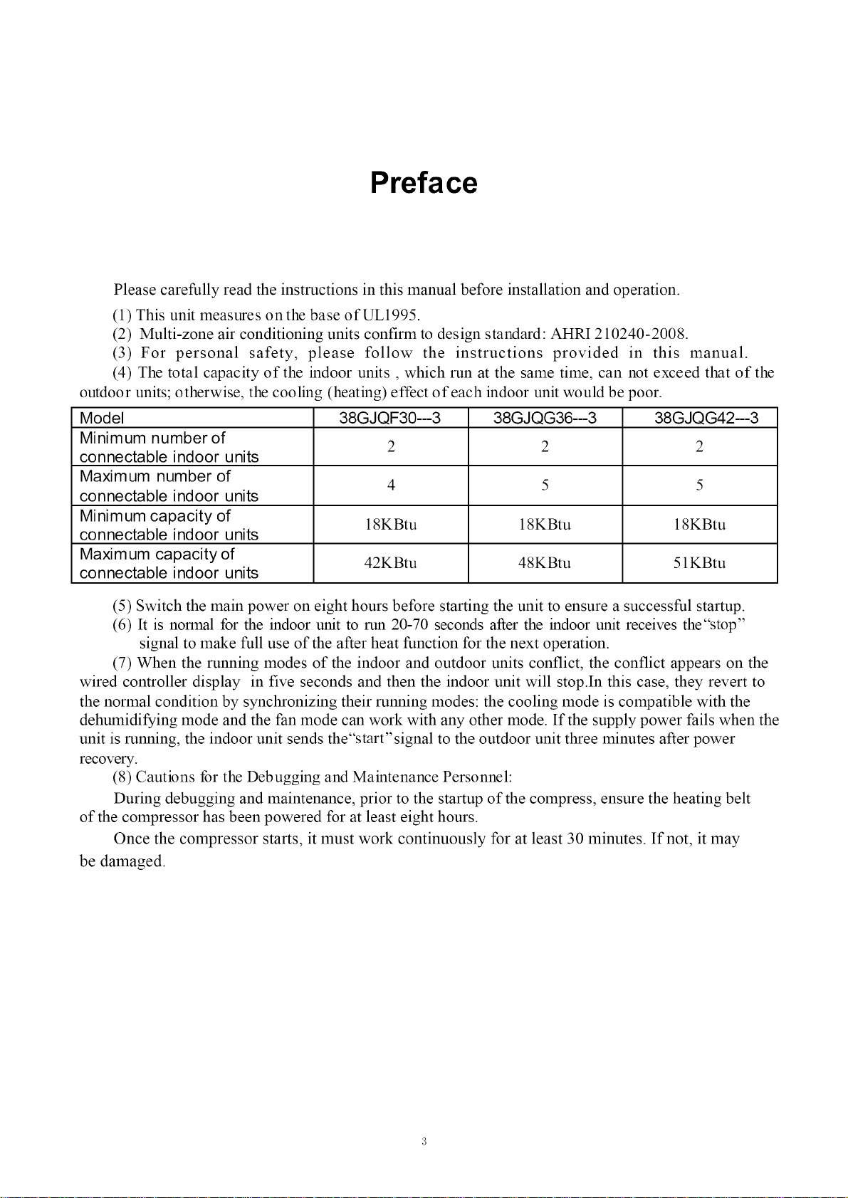
(4) The total capacity of the indoor units , which run at the same time, can not exceed that of the
outdoor units; otherwise, the cooling (heating) effect of each indoor unit would be poor.
Model 38GJQF30--3 38GJQG36--3 38GJQG42--3
Minimum number of
connectable indoor units
Maximum number of
connectable indoor units
Minimum capacity of
connectable indoor units
Maxim um capacity of 42KBtu 48KBtu 51KBtu
connectable indoor units
2 2 2
4 5 5
18KBtu 18KBtu 18KBtu
(5) Switch the main power on eight hours before starting the unit to ensure a successful startup.
(6) It is normal for the indoor unit to run 20-70 seconds after the indoor unit receives the"stop"
signal to make full use of the after heat function for the next operation.
(7) When the running modes of the indoor and outdoor units conflict, the conflict appears on the
wired controller display in five seconds and then the indoor unit will stop.In this case, they revert to
the normal condition by synchronizing their running modes: the cooling mode is compatible with the
dehumidifying mode and the fan mode can work with any other mode. If the supply power fails when the
unit is running, the indoor unit sends the"start'signal to the outdoor unit three minutes after power
recovery.
(8) Cautions for the Debugging and Maintenance Personnel:
During debugging and maintenance, prior to the startup of the compress, ensure the heating belt
of the compressor has been powered for at least eight hours.
Once the compressor starts, it must work continuously for at least 30 minutes. If not, it may
be damaged.
Page 4
2 Product Introduction
The 38GJ system adopts inverter compressor technology. According to change displacement of
compressor, stepless capacity regulation within range of 15%-120% can be realized. Various product lineup is
provided with capacity range from 30KBtu to 42KBtu, which can be widely used in a boarding house, a working area
and especially applicable in a location with a variable load change.
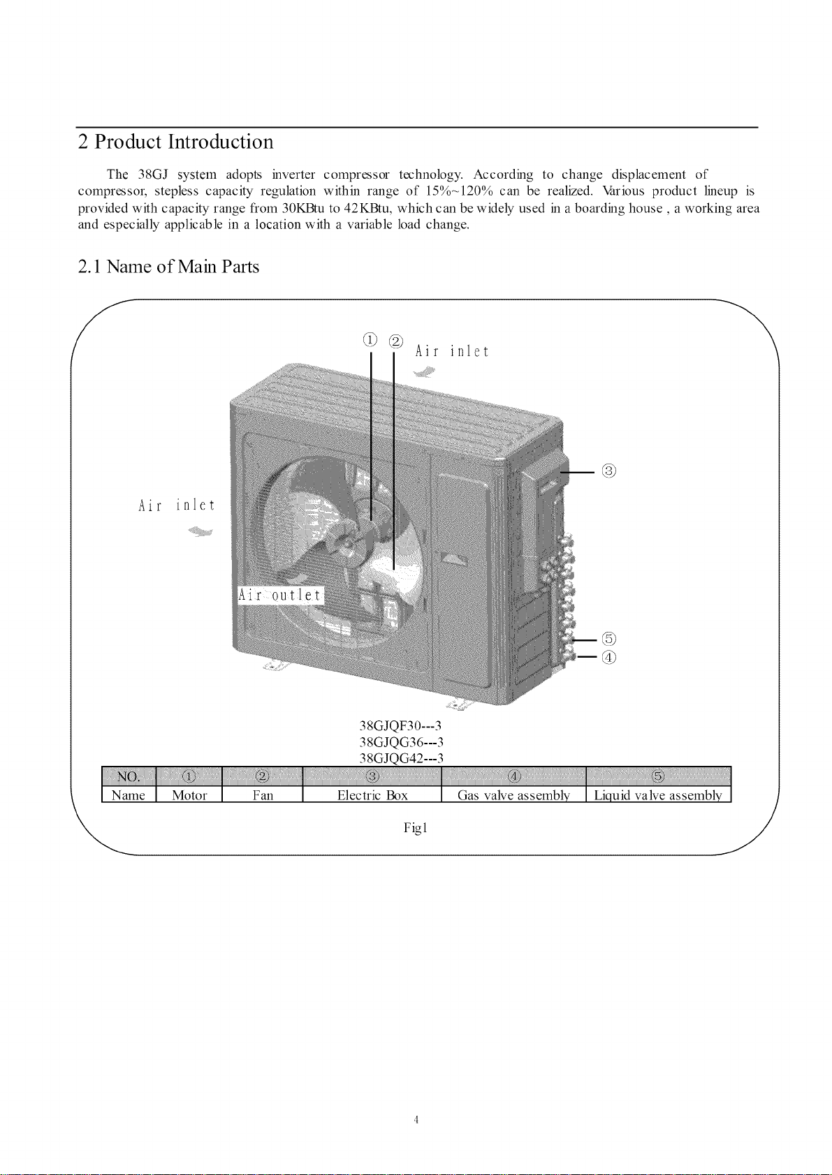
2.1 Name of Main Parts
@ @ Air inlet
@
Air
\
@
38GJQF30---3
38 GJQ G36 --- 3
38GJQG42---3
Fig1
Page 5
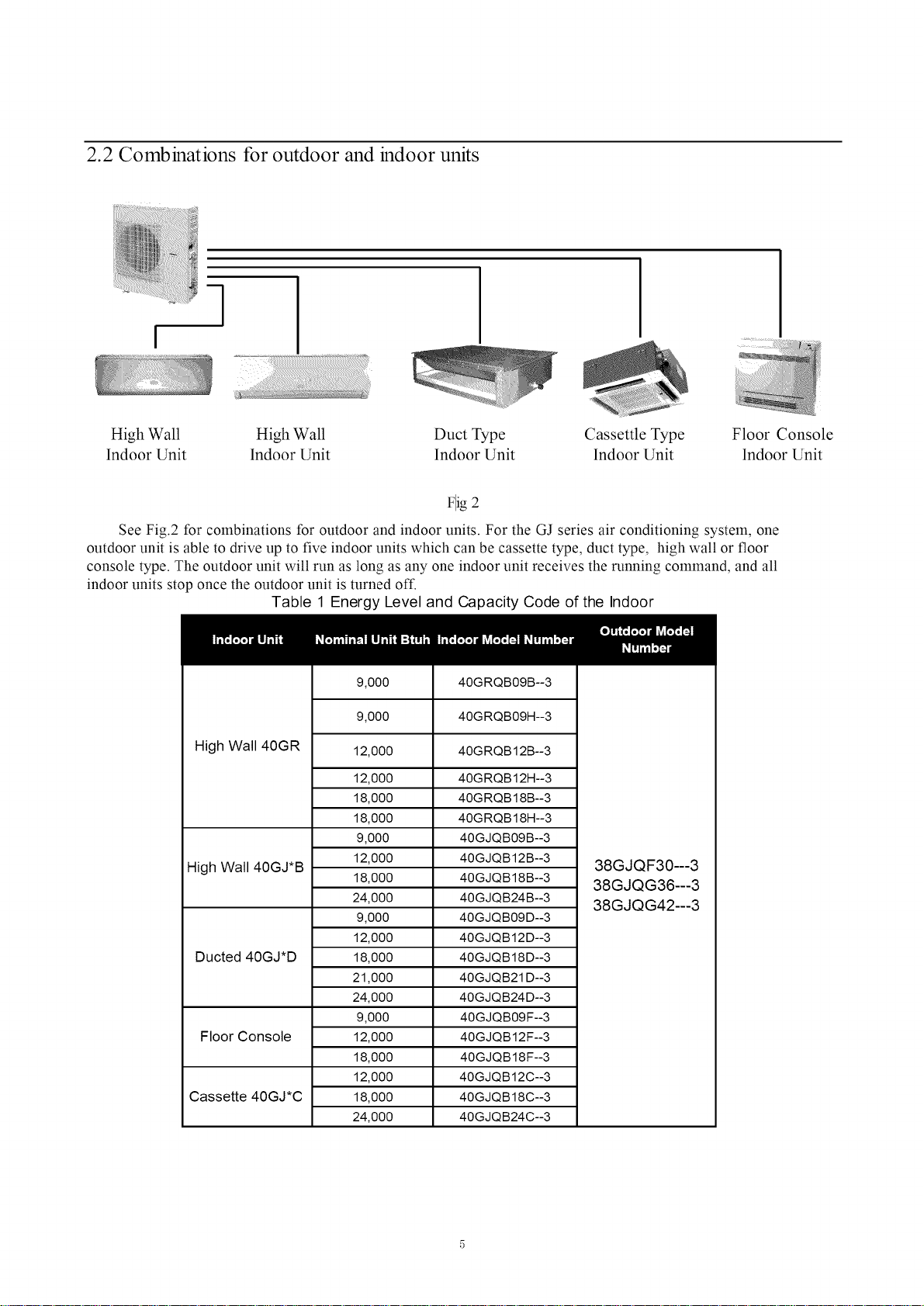
2.2 Combinations for outdoor and indoor units
q
High Wall High Wall Duct Type Cassettle Type Floor Console
lndoor Unit lndoor Unit lndoor Unit lndoor Unit lndoor Unit
Flig 2
See Fig.2 for combinations for outdoor and indoor units. For the GJ series air conditioning system, one
outdoor unit is able to drive up to five indoor units which can be cassette type, duct type, high wall or floor
console type. The outdoor unit will run as long as any one indoor unit receives the running command, and all
indoor units stop once the outdoor unit is turned off.
Table 1 Energy Level and Capacity Code of the Indoor
High Wall 40GR
High Wall 40GJ*B
Ducted 40GJ*D
Floor Console
Cassette 40GJ*C
9,000
9,000
12,000
12,000
18,000
18,000
9,000
12,000
18,000
24,000
9,000
12,000
18,000
21,000
24,000
9,000
12,000
18,000
12,000
18,000
24,000
40GRQB09B--3
40GRQB09H--3
40GRQB12B--3
40GRQB12H--3
40GRQB18B--3
40GRQB18H--3
40GJQB09B--3
40GJQB12B--3
40GJQB18B--3
40GJQB24B--3
40GJQB09D--3
40GJQB12D--3
40GJQB18D--3
40GJQB21 D--3
40GJQB24D--3
40GJQB09F--3
40GJQB12F--3
40GJQB18F--3
40GJQB12C--3
40GJQB18C--3
40GJQB24C--3
38GJQF30---3
38GJQG36---3
38GJQG42---3
Page 6
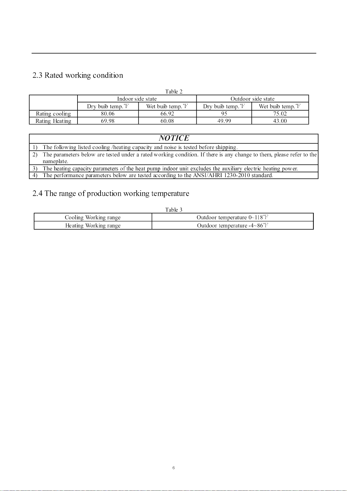
2.3 Rated working condition
Table 2
Rating cooling
Rating Heating
Indoor side state
Dry buib temp. °t: Wet buib temp. °t:
80.06 66.92
69.98 60.08
Dry buib temp. °F Wet buib temp. °F
Outdoor side state
95 75.02
49.99 43.00
NO TICE
1) The following listed cooling/heating capacity and noise is tested before shipping.
2) The parameters below are tested under a rated working condition. If there is any change to thel_ please refer to the
nameplate.
3) The heating capacity parameters of the heat pump indoor unit excludes the auxiliary electric heating power.
4) The performance parameters below are tested according to the ANSI/AHRI 1230-2010 standard.
2.4 The range of production working temperature
Table 3
Cooling Working range Outdoor temperature 0_ 118°F ]
Heating Working range Outdoor temperature -4-86°F
I
Page 7
3 Preparation before Installation
3.1 Standard parts
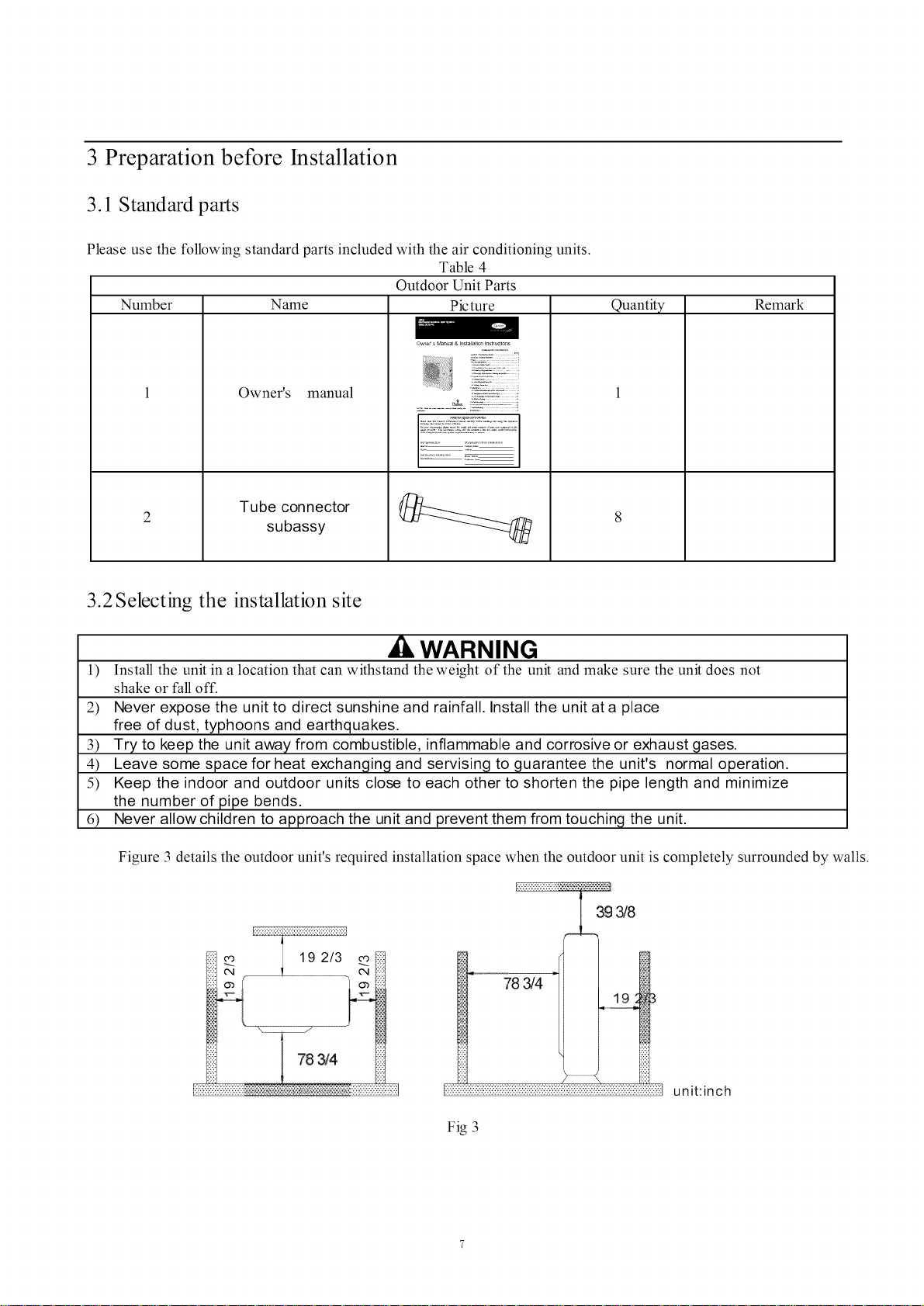
Please use the following standard parts included with the air conditioning units.
Table 4
Outdoor Unit Parts
Number Name Picture
.......................Z47_::oo:o
Owner's manual
;_.;$, :v:,:::v,a..........................
Tube connector
subassy
3.2 Selecting the installation site
Quantity
Remark
WARNING
1) Install the unit in a location that can withstand the weight of the unit and make sure the unit does not
shake or fall off.
2) Never expose the unit to direct sunshine and rainfall. Install the unit at a place
free of dust, typhoons and earthquakes.
3) Try to keep the unit away from combustible, inflammable and corrosive or exhaust gases.
4) Leave some space for heat exchanging and servising to guarantee the unit's normal operation.
5) Keep the indoor and outdoor units close to each other to shorten the pipe length and minimize
the number of pipe bends.
6) Never allow children to approach the unit and prevent them from touching the unit.
Figure 3 details the outdoor unit's required installation space when the outdoor unit is completely surrounded by walls.
3g 3/8
78 _4
unit:inch
Fig 3
Page 8

3.3 Piping Connection
The maximum pipe length is shown in the following table. When the distance between units (piping length) is
out of the range listed below, normal operation of the unit can not be guaranteed.
Table 5
Mode 1
38GJQF30---3
38GJQG36---3
3 8GJQG42---3
Connecting Pipe (inch)
Liquid Gas
@1/4 c_3/8
@1/4 @3/8
@1/4 @3/8
Max. Pipe length(ft)
229.6
246.1
246.1
NOTICE
1) Use water-proof insulating pipe.
2) Wall thickness of pipe: 0.019-0.039 inch; bearing pressure: 3.0MPa
3) The longer the connection pipe is, the more the cooling and heating capacity will decrease.
Max. Height Difference between Indoor
Unit and Outdoor Unit (ft)
When the outdoor unit is above,
the maximum height difference between
the indoor and outdoor units is up to 49.21%
When the indoor unit is above,
the maximum height difference between
the indoor and outdoor units is up to 49.2ft.
Page 9

4 Installation
4.1 Outline and dimension of the outdoor unit
38GJQF30---3
Outline dimension and mounting holes
36 2/9
14 4/7
1
38GJQG36---3, 38GJQG42---3
Outline dimension and mounting holes
38 3/7
362/9
17 1/3
Unit:inch
Fig 4
144/7
38 3/7
17113
Unit:inch
Fig 5
Page 10

4.2 Installation of the Connection Pipe
Connecting piping for the indoor unit and outdoor unit are in the manifold mode (see the figure below).
/tlliiti
I
Fig6
4.2.1 Piping between the Indoor and Outdoor Units
(1) If the liquid and gas stop valves, which have the sign A, 13, C, D or E , have not been connected to the
indoor units, turn off the screw cap with the spanner airproof.
(2) Refer to Fig.7 for the appropriate amount of torque to tighten the screws.
(3) Point the flare end of the copper pipe at the screw and tighten the screw by hand.
(4) Next, tighten the screw with the torque wrench until it emits a sound (as shown in Fig.7).
(5) The bending degree of the pipe can not be too small; otherwise it will crack Use a pipe tube
bender to bend the pipe.
(6) Wrap the exposed refrig_ipe and the joints by sponge and then tighten them with the plastic tape.
':?' :¢ "" "75"
Spanner .................//
Pipe Flare Nut Pipe
Torque Wrench
Fid 7
Pipe Thickness of Tightening
diameter copper tube torque
qbl/4 inch >0.0315 inch 11--22 ft.lbf
qb3/8 inch >0.0315 inch 26--29 ft.lbf
qbl/2 inch >0.0315 inch 33--37 ft.lbf
qb5/8 inch >0.0394 inch 44--48 ft.lbf
ACAUTION
1) During the connection of the indoor unit and the refrigerant pipe, never pull the indoor unit joints forcefully,
otherwise the capillary or other pipes may crack, which would result in leakage.
2) The refrigerant pipe should be supported by brackets. Do not allow the unit to support the weight of the refrigerant pipe.
3) If the piping connection size of the outdoor unit does not match the piping connection size of the indoor unit, use the
piping connection dimension of the indoor unit. Use different-diameter joints which is installing on the place of
the piping connection to connect the indoor unit.
4) For the Free Match system, each pipe should be labeled to indicate which system it belongs to avoid mistaken
inaccurate piping.
4.2.2 Allowable pipe length and drop height among indoor and outdoor units
If the total refrigerant pipe length (liquid pipe)
refrigerant will be charged.
Model
Total Liquid Pipe
Length (a+b+c+d+e)
38GJQF30---3
131.2ft
is shorter than that listed in the table below, no additional
Table 6
38GJQG36---3 38GJQG42---3
131.2ft 131.2ft
10
Page 11

Allowable Length and Height for the Refrigerant Pipe
38GJQF30---3
Total length (actual length) of fitting
229.6ft
pipe
Length of farthest fitting pipe (ft)
Table 7
Allowable Value
82ft
38GJQG36---3
38GJQG42---3
246.1 ft
82ft
Fitting P ipe
LI÷L2+-"+I. M(M 45)
Lx (X-I, 2, 3, 4,5)
Height difference
Outdoor unit at
between outdoor upper
unit and indoor unit Outdoor unit at
low er
Height difference between indoor
units (m)
C
o
o
C
C
o
'o
C
C
(1)
_D
..Q
00
O
¢-
"CJ
c_
I
Outdoor unt
L1
49.2ft
49.2ft
24.6ft
49.2ft
49.2ft
24.6ft
Equivalent length of the farthest fitting pipe Lx
L2
L3
L4
b
Indoor unit
c
Fig 8
d
H1
H3
H2
L5
e
11
Page 12

4.2.3 Oil Trap Design Requirements
If theheight differencebetweentheindoor unitandthe outdoorunitexceeds19.7ft(6m), installan oil trapevery19.7ft(6m)from
the lower to the upper section of the vertical gas pipe. The oil trap shall be fabricated into two U-type
elbows or one return-type elbow. The height shall be 3~5 times the piping diameter.
See below for details on the installation and fabrication of the oil trap.
_. The oil trap may be fabricated into a U-type or return-type.
If the outdoor unit is below the indoor unit, it is not needed to install an oil trap on the vertical pipe for gas piping.
@. If the outdoor unit is below the indoor unit, it is not needed to install an oil trap at the highest or lowest
position. If the outdoor unit is above the indoor unit, the oil trap and stop elbow must be installed at the lowest and
the highest position of the vertical pipe. Refer to the schematics below.
_. The fabrication dimensions of the oil trap are shown below.
¢3/4i n (19.05m
@. Refer to the schematics below.
• The outdoor unit is lower than the indoor unit.
Gas pipe
Liquid pipe
Oiltrap
Stopelbow
Indoor
unit
19.7ft (6m)
19.7ft (6m)
19.7ft (6m)
Outdoor
unit
/
19.7ft (6m)
19.7ft (6m)
12
Page 13

• Theoutdoorunitis higherthantheindoorunit.
Stopelbow
/
/
Outdoor
unit
Gas pipe
Liquid
19.7ft (6m)
19.7ft (6m)
19.7ft (6m)
Oiltrap
19.7ft (6m)
19.7ft (6m)
Oil returntrap
Indoor
unit
4.2.4 Installation of the Refrigerant Pipe Protection Layer
The refrigerant refrigerant pipe should be insulated by the insulating material and plastic tape to prevent
condensation and water leakage.
The joints of the indoor unit should be wrapped with the insulating material.Ensure there is no gap on the joint
of the indoor unit, as shown in Fi .9.
The thermal insulating layer is required to be wrapped at this part.
Fig9
13
Page 14

,A CAUTION
Alter the pipe is protected, do not bend it to form a small angle; otherwise it will crack or
break.
(3)Wrap the Pipe with Tape:
a. Bundle the refrigerant pipe and electric wire together with tape, and separate them from the drain pipe to
prevent the condensate water from overflowing.
b. Wrap the pipe from the bottom of the outdoor unit to the top of the pipe where it enters the wall. During the
wrapping, the later circle should cover half of the former one.
c. Fix the wrapped pipe on the wall with clan_s. AUT_ON_"
1) Do not wrap the pipe too tight; otherwise the insulation effect would be weakened.Ensure
drain hose is separated from the pipe.
2) Next, fillthe hole on the wall with sealing material to prevent wind and rain from entering the room.
4.2.5 Support and protection for the pipeline
Support should be made for hanging the connection pipe. The distance between each supportcan not exceed 3.3 fl (hn).
4.3 Air Purging and Refrigerant Charge
4.3.1 Air purging
(1) The refrigerant in the outdoor unit was charged before shipment. Additional refrigerant needs to
be charged into the refrigerant pipe during the field installation.
(2) Ensure the outdoor unit's liquid and gas valves are closed completely.
(3) As shown in the following figure (Fig. 10), expel the gas inside the indoor unit and the refrigerant pipe with the
vacuum pump.
"LO"Knob
liquid valve
\
\,
\
Manometer
[i:::i
\
Connection hose
,::Gas xa!ve
Manometer
/
/
f
_/= :_: Vacuum pump
"Hl"Knob
f
/
/
//
Fig 10
(4) When the compressor is not running, charge the R410A refrigerant into the refrigerant pipe from the liquid
valve of the outdoor unit (do not charge from the gas valve).
4.3.2 Additional refrigerant charging
(1) Refrigerant Charge in the Outdoor Unit before Shipment
NO TICE
1) The outdoor unit has been charged with refrigerant prior to delivery. The refrigerant charge is not included and is
an additional charge for the indoor unit and the refrigerant pipe.
2) The amount of the additional refrigerant charge depends on the diameter and length of the liquid refrigerant
pipe which is determined by the actual yield installation requirement.
3) Record the additional refrigerant charge for future maintenance.
14
Page 15

(2) Calculation of the Additional Refrigerant Charge
Additional Refrigerant Charge-
(EI.ength of' Liquid Pipe_b0.375X54+ELength of Liquid Pipe {b0. 25 X 22) 880
The largest additional refrigerant charge value is 800g.This means if the calculated value exceeds 800g, the
additional refrigerant charge takes 800g, while the calculated value takes less than 800g, the additional refrigerant charge
takes the calculated value.
4.4 Electric Wiring
4.4.1 Wiring precautions
(1) The installation must be done in accordance with the national wiring regulations.
(2) Only a power cord with the rated voltage and exclusive circuit for the air conditioning can be used.
(3) Do not pull the power cord forcefully.
(4) The electric installation should be performed by a technician instructed in the local laws, regulations
and this manual.
(5) The diameter of the power cord should be large enough for the unit. If the cord is damaged, it must be replaced by the
dedicated one.
(6) The ground should be firm and the earth wire should be connected to the dedicated device of the building
by the technician.The air switch coupled with the leakage current protection switch must be equipped and have
enough capacity in both the magnetic and the_Tnaltripping functions in case of the short circuit and overload.
Table 8
Models Power Supply Capacity of the air Switch (A)
38GJQF30---3 208/230V-60Hz 32 3 X 0.0062 sq in
38GJQG36---3 208/230V-60Hz 32 3 X 0.0062 sq in
38GJQG42---3 208/230V_60Hz 32 3 X 0.0062 sq in
Recommended Cord (pieces X
sectional area)
38GJ_QF30---3
0UTD00t{ UNIT
IT IT 1 IT2 IT3 IT4
_ N(1) 2 3 N(1) 2 3 N(1) 2 3
/
In ..... I I , II n..... I
POWEt{ [IND()()t{ UNIT AI [INDO0t{ UNII B I IINDOOR UNIT C I [INDO()t{ UNII DI
Fig 11
PE
15
Page 16

38GJQG36---3,38GJQG42---3
r 1
i OUTDOORUNIT
Ii XT XT1 XT2 XT3 XT4 XT5 I
N(1) 2 3 N(1) 2 3 N(1) 2 3 N(1) 2 3 N(1) 2 3
--_ PE _) PE PE PE PE PE
1
POWER i INDOORUNIT A I INDOORUNIT B i INDOORUNIT C ii INDOORUNIT D I INDOORUNIT EI
Fig 12
4.4.2 Grounding Require ments
(1) The air conditioner is classified as a Class I appliance, so its grounding must be reliable.
(2) The yellow-green line of the air conditioner is the earth line and can not be used for any other purpose, cut off or
fixed by the tapping screw; otherwise it would cause an electric shock.
(3) A reliable ground terminal should be provided and the ground wire can not be connected to any of the following
items:
@Running water pipe @Coal gas pipe @Sewage pipe @Other places where the professional personnel
think unreliable.
4.4.3 Electrical Cable Connection
A CAUTION
1) A mistake connecting the line will result in a malfunction. After the electrical wiring is working, ensure
the wire between the connection place and the fixed place has a certain amount of space.
2) The connection piping and connection line of each indoor unit should connectwell according to the instruction.
3) The electric installation should be carried out by a technician instructed in the local laws, regulations and
this manual.
4) The installation location should be dry, shielded from direct sunlight or strong winds.
5) Install a breaker in the circuit that can shut off the system's main power supply. Also install an air
switch coupled with the leakage current protection switch must be equipped.
4.4.4 Wiring of the Power Cord
(1). Open the side plate.
(2). Connect the power cord to terminals "L1 ", "L2" and the earthing bolt. Next, connect the wiring
terminals "N(1),2,3" of the indoor unit to the corresponding outdoor unit terminals.
(3). Fix the power cordwith wire clips.
(4). Place the power cord through the rubber ring.
,A,CAUTION
If the supply cord is damaged, it must be replaced by the manufacturer or its service agent or a similarly
qualified person to avoid a hazard.
16
Page 17

5 Troubleshooting
WARNING
1) In the event of abnormal conditions (for example, a foul smell), shut off the main power supply inmlediately and
contact your Service Center.Operating under abnormal conditions would damage the
air conditioning unit and would cause electric shock or a fire hazard.
2) Do not attempt to repair the air conditioning.Contact a professionally skilled technician at the
appointed service center. An incorrect repair would cause electric shock or a fire hazard.
Check before Contacting Service Center.
Table 9
Check Items
Has the unit been secured firmly?
Have you done the gas leakage test?
Does the unit have proper thermal insulatio
Does the unit drain well?
Is the voltage in accordance with the
rated voltage specified on the nameplate?
Is the electric wiring and piping
connection installed correctly and
securely?
Has the unit been earthed securely?
Is the power cord specified?
Has the inlet and outlet been blocked?
It may cause insufficient cooling/heating
capacity.
1? It may cause condensation and drippil
It may cause condensation and dripping.
It may cause a malfunction or damage the part.
It may cause malfunction or damage the part.
It may cause electrical leakage.
It may cause malfunction or damage the part.
It may cause insufficient cooling/heating
capacity.
Conditions Might Happen
The unit may drop, shake or emit noise
NOTICE!
If the air conditioner still runs abnormally after the above checks, please contact a
maintenance serviceman at the local appointed service center and provide a description of the error
as well as the model of the unit.
Check
17
Page 18

6 The conditions listed below are not classified into errors.
Table 10
Conditions
The unit does not run
The unit blows out mist
The unit generates noise
The unit blows out dust.
When restarted ilnlnediately after it
was stopped.
As soon as power is on.
When the cooling operation starts.
The unit "clatters" as soon as it
starts running.
The unit "swishes" during the
cooling operation.
The unit "swishes " when it
starts or stops.
The unit "swishes" when it is on
and after it runs.
The unit "squeaks" when it is on
and after it runs.
When the unit restarts after
The overload protection switch of the unit
delays the startup for three minutes.
The unit remains in stand by mode for
approximately one minute.
The hi-humidity indoor air is cooled quickly.
It is the sound generated during the initialization
of the electronic expansion valve.
It is the sound of the refrigerant gas that runs inside
the unit.
It is the sound of the refrigerant gas as it stops
running.
It is the sound of the draining system
operating.
It is the sound of friction generated by the skin
plate which swells due to the temperature
change.
The dust inside the unit is blown out.
not running for a long time.
The unit emits odors.
When the unit is running.
The odors absorbed by the unit are blown out.
NOTICE!
If problem can not be solved after checking the above items, #ease contact service center and provide
details and model(s).
The following conditions are not malfunctions.
malfunctions Table 11
Malfunction
Unit does not run
Mist comes from the
unit
Noise is emitted
When the unit is started
immediately after it is just
turned off
When power is turned on
Under cooling
Slight cracking sound is heard
when unit is turned on
Overload protection function provides a 3 minute
delay
Standby function delays operation for about 1 minute
Indoor high humidity air is cooled rapidly
It is the sound generated during the initialization of the
electronic expansion valve.
Causes
Re ason
The unit blows out
dust
The unit emits odor
Indoor unit still runs
after turned off
There is sound
when cooling
There is sound when the unit starts
or stops
There is a slight and repetitive
sound when the unit is running o_
after running
A cracking sound is heard when
the unit is operating and after
operating
When the unit runs after
not running for a long time.
Operating
After every indoor unit receive
"stop" signal, fan keeps
The gas refrigerant is flowing in unit
The gas refrigerant has stopped flowing
This is the sound of the drainage system.
The sound is caused by expansion of the panel and other
parts due to temperature change
Dust in the indoor unit is blown out
The room odor absorbed by the unit is blown out
Indoor fan motor keep running 20-70s to make
good use of excess cooling and heating and to prepare for
18
Page 19

running
next operation
Mode conflict
COOL or HEAT mode can not
be operated
When the indoor operating mode conflicts with that of
outdoor unit, the indoor fault indicator flashes and the
conflict appears on the wired controller after 5 minutes.
The indoor unit stops. The outdoor operating mode
switches to the mode of the indoor unit. Next,
the unit returns to normal. The COOL mode does not
conflict with the DRY mode. The FAN mode does not
conflict with any mode.
19
Page 20

7 Troubleshooting
The error code displays on the wired conlroller and the main board of the outdoor unit
Table 12 details the meaning of each error.
Table 12
Malfunction
Compressor runs
Defrost
Anti-freezing protection
IPM protection
AC over-c urrent protec tion
Over-burden protection
Compressor exhaust high temperature protection
Compressor overload protection
Power protection
EEPROM reads and write protection
Low PN voltage protection
Over voltage protection for PN
PFC protection
PFC module temperature protection
Low pressure protection
High pressure protection
Linlit/decline frequency(electric current) Flash 1 times
Frequency limit (exhaust) Flash 2 times
Frequency limit (Over-burden) Flash 3 times
Outdoor ambient sensor malfunction Flash 6 times
Outdoor tube sensor malfunction Flash 5 times
Exhaust sensor malfunction Flash 7 times
Attain the temperature of switch on Flash 8 times
Frequency limit(power) Flash 13 times
Outdoor fan malfunction Flash 14 times
Frequency limit(PFC module temperature) Flash 15 times
PFC module sensor malfunction Flash 16 times
Liquid pipe temperature sensor malfunction of A Flash 17 times
Gas pipe temperature sensor malfunction of A Flash 18 times
Liquid pipe temperature sensor malfunction of B Flash 19 times
Gas pipe temperature sensor malfunction of B Flash 20 times
Liquid pipe temperature sensor malfunction of C Flash 21 times
Gas pipe temperature sensor malfunction of C Flash 22 times
Liquid pipe temperature sensor malfunction of D Flash 23 times
Gas pipe temperature sensor malfunction of D Flash 24 times
Liquid pipe temperature sensor malfunction of E Flash 25 times
Gas pipe temperature sensor malfunction of E Flash 26 times
Exit of the condenser tube sensor malfunction Flash 27 times
Correspondence is normal unit number)
Communication failure between indoor unit and ( indoor unit all
outdoor unit Communication failure )
Yellow light
Flash once
Flash twice
Flash 3 times
Flash 4 times
Flash 5 times
Flash 6 times
Flash 7 times
Flash 8 times
Flash 9 times
Flash 11 times
Flash 12 times
Flash 13 times
Flash 14 times
Flash 15 times
Flash 17 times
Flash 18 times
The indicator display
Red light Green light
Flash n times (n=indoor
Often bright
2O
Page 21

8 Maintenance
A regular inspection, maintenance and care should be performed by professional personnel, which will prolong the unit's
life span.
8.1 Outdoor heat exchanger
The outdoor heat exchanger should be cleaned once every two months. Use a vacuum cleaner with a nylon brush
to clean up dust and small particles on the surface of the heat exchanger. Blow away dust with compressed air, if available.
Never use water to wash the heat exchanger.
8.2 Drain Pipe
Regularly check if the drain pipe is clogged to drain condensate smoothly.
8.3 Notice before Seasonal Use
(1) Check if the inlet/outlet of the indoor/outdoor unit is clogged.
(2) Check if the ground wire is earthed reliably.
(3) Check if the battery of remote wireless controller has been replaced.
(4) Check if the filter screen has been set correctly.
(5) After a long period ofnonuse, open the main power switch 8 hours before re-operating the unit to
preheat the compressor crankc ase.
(6) Check if the outdoor unit is installed securely. If there is anything abnormal, contact the
appointed service center.
8.4 Maintenance after Seasonal Use
(1) Cut off the main power supply to the unit.
(2) Clean the filter screen and the indoor and outdoor units.
(3) Clean the dust and small particles on the indoor and outdoor units.
(4) In the event of rusting, use anti-rust paint to stop t h e spreading of rust.
8.5 Parts Replacement
Purchase parts from an appointed service center or dealer if necessary.
NOTICE!
During the airtight and leakage test, never mix oxygen, ethyne and other dangerous gas into the refrigeration
circuit. In case of hazard, it is better to use nitrogen or refrigerant to perform the test.
21
Page 22

(opyri_ht 2014 (arz'iez"(orporationS 7310W. \[orz'isSt. S Indianapolis, IN 46231 Edition Date:llA4
\!tmufacturerresez'vesthe ri_ht to change, at any time, speeifict_tionsanddesigns wid_out notice and without obli_ations.
Catalog No: 380J 30 42 010M
Replaces;New
1
66129917007
 Loading...