

Page 1
Carrier
38GC
Æ
c? -1
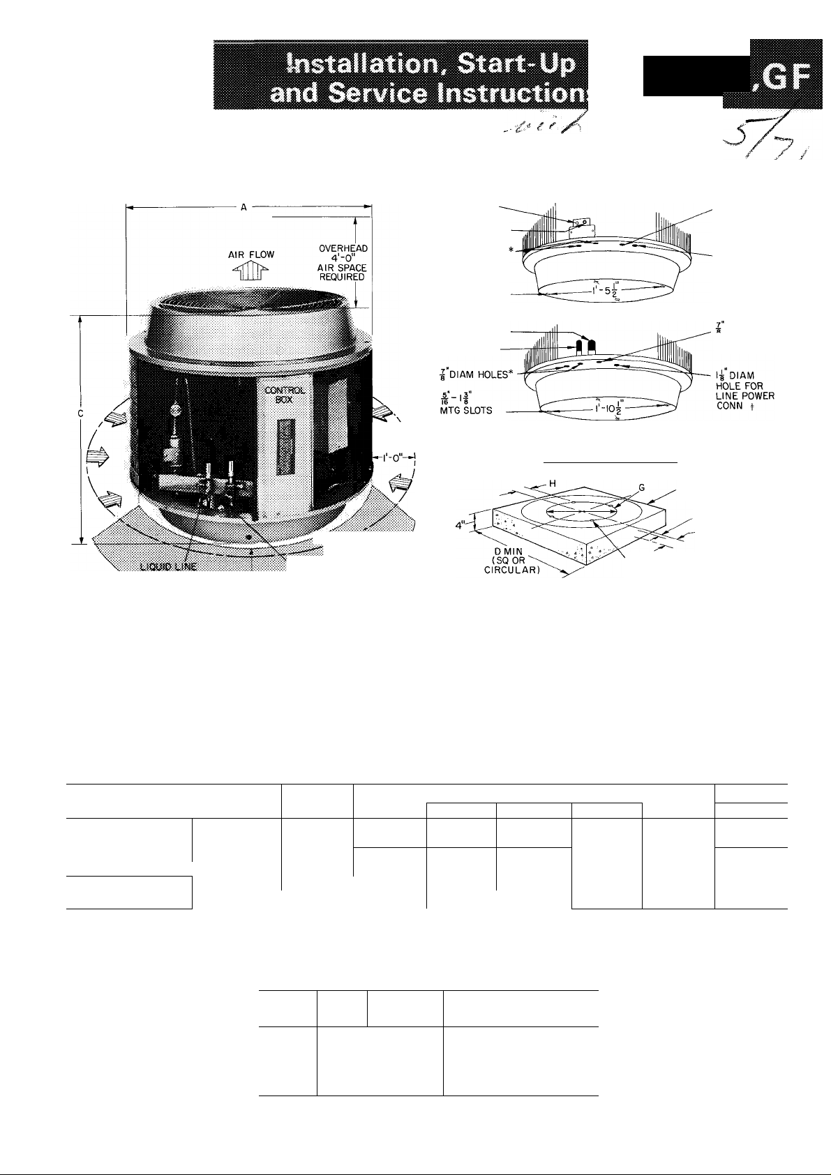
Air-Cooled Condensing Units
LIQUID LINE
SUCTION LINE
J'dIAM HOLES
MTG SLOTS
\
AIR FLOW
CLEARANCE
(USE ANY TWO)
SUCTION LINE
LIQUID LINE
(USE ANY TWO)
BOTTOM VIEW 38GC10I; 38GC,GFI02,103
BOTTOM VIEW 38GC.GFI04,145,105; 38GFI06
CONCRETE MOUNTING PAD
I DIAM HOLE
FOR CONTROL
POWER CONN t
1-^" DIAM
HOLE FOR
LINE POWER
CONN
DIAM HOLE
FOR CONTROL
POWER CONN t
CONCRETE PAD **
(SQ OR CIRCULAR)
E SUCTION LINE
F LIQUID LINE
rjfiN
SJCT^UM
S'-cr
t
*Two plugged holes to accommodate charging lines Replace plugs when finished
tl nsert rubber grommet (shipped in low voltage splice box) in hole to protect wires if conduit is not used
J1-3/8 in diam on 38GF106 single-phase units
**Concrete pad should weigh 1 -1 /2 to 2 times weight of unit
Fig. 1 — Dimensions, Connections and Mounting Pad (Unit Access Panel Removed)
Table 1 — Installation Data
CO ND E NS IN G U N IT
OP ER A TI NG
WT (l b)
DIM E NS IO N S
(ft-i n. )
RE FR IG E RA N T
CO NN , (in .)
_______
j 38GF units only, field-supplied tubing sizes for oil return and refrigerant charge
*38GF006 supplied with 3/4 to 1 -1 /8 in suction valve connection adapter (field-installed)
38G C
38G F
Dia m A
Hei gh t C
Sue t OD F V,
Liq O DF
38G C
101
111 13 2
- 136
2-0% 2-0 ^4 2-0%
2-1 Vi 6
%
102 103
2-3 Vi 6
=/s
'/b
illl SPACE REQUIRED FOR SERVICE
149 16 5
154 16 9
2-3%,
% ^/4
% %
CONDENSER AIR FLOW
38G C .G F
104
2-5% 2-5%
2-1 Vi 6
TIE DOWN B0LTS(i-20x lin )
(USE ANY TWO LOCATIONS,
180“ APART)
145
207
211
2-5%,
'%
38G F
105 106 *
220
224 250
2-5 ^4
2-5 V, 6
V4
Vb
2-5%
_
2-7%,
IV3
%
© Carrier Corporation 1971
Table 2 — Pad Dimensions (ft—in.)
DIM .
D
E
F
G
H
38G C
101
i6ï, ^T 03 ~~ “
-3
0-2%
0-3V, 0- 7%
-5%
0-1 %
GC ,G F 1 3 8 GF
38
" 10 4 , 1 45 , 1 0 5 " j 1 0 6
2-1 0
0- 4 %
1-1 0%
0- 2
Form 38GC-15SI
Page 2

Table 3 — Accessories
PART
NUMBER
Auxiliary Start’ Capacitor and Relay Package
38GC900001
38GF900132
38GC9000132
38GC9000371
32LM001301
HH0UD038
HH01AZ039
58BV90008Í
58BV900101
38GB9000Í21
38GF900072
'38^GC900152
38GC900031
38GC900041
38GC900051
38GC900061
38GC900191
38GC900181 50
38GC900071
38GC900081
38GC900091
38GC900101
38GC900in
^Standard equipment on all current single-phase units except 38GC101,
102, 103 and 38GF102
fMotor used with units equipped with 06R compressor For all other
units, use fan motor HC38VQ700.
$For 5/8-in evap connection, cut off 3/4-in. end
NOTE All suction lines have a 90-degree bend at one end
(single-phase units)
38GC101
38GC102, 103; 38GF102 (six 38GF900121)
Low Voltage (24 v) Control Transformer
(standard on 38GF units)
38GC101, 102, 145, 105 (six 38GC9000121; 20 va)
38GC103, 104 (six 38GC9000361; 40 va).
Solid State Head Pressure Control. Special fieldinstalled fan motor required on 102 thru 145 units.
UNIT
MOTOR
Low Voltage Control (heat—cool)
Thermostat
Cooling Switch Base
Low Voltage Control (heat—cool) — Grayson
Thermostat (six HH01YA092)
Cooling Switch Base (six HH93YZ094)
Expansion Valve Package (six EA16DC100
38GF102, 103, 104)
Expansion Valve Package (six EA12XC400 —
38GF145, 105, 106)
Indoor Fan Relay (six 38BA400693)
Precharged Tubing (not available for 38GF106
Units)
Lgth
(ft)
35
38GF102 38GF103t 38GF104t
NO. 500011
10
18
25
50
10
18
25
35
50
38GF 38GF
UQ
UID
OD
(in.)
Vs
Vs
Vis
Vis
Vs
Vs
Vs
3/
3/
Vs
Vs
DESCRIPTION
Fan Motor Carrier Part No.
50001 It VE230t VL700
SUCTION
Tube End
Tube End
OD (in.)
4
Vs
Vs
4
V
4
V
4
V
V
3/
4
Vs
Vs
(in.)
Vs
%
%
Vs
V
4
V
4
V
V
4
V
4
4
OD (in.)
Evap
Vst
Vst
Vt
Vst
Vt Vs
Vst
V V
Vs
V
V
4 V
4
HC38
___
Con8
Vs
Vs
V
V
Vs
V
V
4
4
4
38GF145
HC40
Honeywel I
__ _ __
UNITOD
3800101,102,
103, 38GF102
38GC101,102,
38GF102
38GC103
38GC104,145,
105, 38GF103,
104,145,105
TRANSPORTATION DAMAGE
File claim with shipping company if shipment is
damaged or incomplete.
SKID REMOVAL
Move condensing unit to final location. Remove top
grille. Reach between fan blades and remove 1/4-in.
hex head screws holding unit to skid. On the 145, 105,
106 units, remove the two compressor shipping brackets
attached to top of compressor and sides of unit.
PRELIMINARY SURVEY
Consult local building codes for special installa
tion requirements.
When installing unit, allow sufficient space for
air-flow clearance, wiring, refrigerant piping and
servicing unit. NEC minimum requirement is 3 ft
(see Fig. 1). Position unit so water from roof or
eaves will not pour directly on top of unit.
Install unit on a solid, level mounting pad.
Position tie-down bolts in pad. Any two holes in
unit base may be used to fasten unit to pad.
38GC,GF Condensing Units are designed for appli
cation with any Carrier or other evaporator of
proper capacity. Install each unit in accordance
with Refrigerant Piping Data, (Table 4) and the
following special requirements.
Where refrigerant line lengths exceed 25 ft, it is
recommended that a liquid line filter-drier, crank
case heater and accessory start capacitor with relay
be added to condensing unit.
Liquid line filter-drier and crankcase heater are
factory installed on 38GF units. Start capacitor
with relay is available as an accessory for
38GC101, 102, 103 and 38GF102; factory in
stalled on remaining sizes.
When evaporator is below condensing unit,
reduce liquid line size one diameter (min 114-in.
OD).
PIPING CONNECTIONS
38GC,GF Condensing Units can be connected to
evaporator sections using Carrier accessory pre
charged tubing or field-supplied tubing of refrig
erant grade. (Accessory tubing not available for
38GF106.) See Table 3 for accessory tubing sizes
and Table 4 for recommended field-supplied tubing
sizes. When over 25 ft of interconnecting tubing is
used, follow special requirements described above
in Preliminary Survey. Do not use damaged or
contaminated tubing. Do not cut 3/8-in. OD liquid
line to a length shorter than 10 ft. Bend or coil to
fit. When precharged tubing or evaporator section
has been open for more than 15 seconds per
connection, evacuate or purge evaporator coil and
tubing system (use field-supplied refrigerant, not
unit refrigerant). If necessary, refer to Carrier
System Design Manual, Part 3, for standard piping
techniques.
38GC,GF Connection Procedure — When making
piping connections, be sure to provide clearance at
unit for electrical connections.
Connect refrigerant liquid and suction lines to
condensing unit (Fig. 1). Unit Compatible Fitting
permits two methods of refrigerant line connec
tion. mechanical (quick-connect) or sweat
connection.
38GF106 UNITS — Remove suction line adapter
taped to compressor shipping bracket and connect
to suction line Compatible Fitting. Sweat connect
refrigerant suction line to adapter. Connect liquid
refrigerant line to unit.
2
Page 3

(Mate one set ofMECHANICAL CONNECTION
connections at a time).
1. Loosen nut on Compatible Fitting one turn. Do
not remove. Loosen tube clamp.
2. Remove rubber plug and be sure 0-ring is in the
groove inside the Compatible Fitting.
3. Cut tubing to correct length.
4. Use gage on tag attached to service valve to
mark tube end for correct insertion depth.
Insert tube into Compatible Fitting until it
bottoms. (Tube should be inserted at least as
far as mark on tubing.)
5. Tighten nut until it bottoms on back coupling
flange. Tighten tube clamp.
SWEAT CONNECTION (use refrigerant grade
tubing).
1. Remove locking nut and rubber 0-iing from
inside of fitting. Loosen tube clamp entering
condensing unit base.
2.
Cut tubing to correct length.
3.
Insert tube into Compatible Fitting. Wrap top
and bottom of service valves in wet cloth to
prevent damage by heat. Solder with low
temperature (450 F) silver alloy solder. Tighten
tube clamp.
4.
Evacuate or purge system with field-supplied
refrigerant.
ELECTRICAL DATA AND WIRING
Wiring — Field wiring must comply with local and
national codes. Install a branch circuit fused
disconnect of adequate size to handle starting
current. When making electrical connections, pro
vide clearance at unit for refrigerant piping
connections.
LINE POWER is brought thru unit base pan flange
and thru hole provided in control box (Fig. 1). On
38GC101, 38GF106 (230-v, 1-ph) and 38GF103,
104 (208- and 230-v, 3-ph) units, line power
connections are made to pigtails supplied with
unit. Use approved splice connector. Do not use
aluminum field wire for splice connections unless
copper to aluminum adapters is used, and correct
wiring techniques are followed.
On all other models connect line power to
contactor screw power terminals as indicated on
unit label diagram, i.e., connect power leads to
contactor terminals 21 and 23 on single-phase
units, or 21, 22, and 23 on 3-phase units.
On all 3-phase units, do not connect a grounded
high voltage leg to control circuit pigtail or
terminal; connect leg to compressor pigtail or
terminal. See label diagram.
CONTROL POWER is brought thru unit base pan
(Fig. 1), and thru 7/8-in. hole into low voltage
section of control box. All connections are made
to pigtails supplied with unit (Fig. 2). Where
supply voltage exceeds 150 volts to ground, or
local codes require it, ground 24-volt control
circuit at field splice C.
Table 4 — Refrigerant Piping Data
Crankcase heater (standard on GF), liquid line filter-drier (standard on GF)
and start capacitor with relay (accessory on GC101, 102, 103 and GF102)
required Reduce liquid line size one diameter (mini /4-in OD) when evaporator
is below condensing unit
TXV — Thermal Expansion Valve
Cap. Tube — Capillary Tube
*3/4-in on 38GF.
Page 4

THERMOSTAT SUBBASE TERMINALS
(HH93AZ039 OR HH93YZ094)*
Arrangement A — Transformer External to
Condensing Unit (38GC Only)
THERMOSTAT SUBBASE TERMINALS
(HH93AZ039 OR HH93YZ094)*
Arrangement B — Transformer in Condensing Unit
THERMOSTAT SUBBASE TERMINALS
(HH93AZ039 OR HH93YZ094)*
LEGEND
C — Contactor IFM — Indoor Fan Motor
CR — Control Relay IFR — Indoor Fan Relay
FS — Fan Switch LPS — Low-Pressure Switch (see Note 2)
HC — Heating Control Tran - Transformer
A Field Splice
_______
Field Wiring
_______
Factory Wiring
*Accessory (transformer standard on 38GF units)
fl nstall jumper between j^and when one 24-volt transformer is
used (Jumper supplied on HH93YZ094 )
ijiConnect to low speed indoor fan terminal when 2-speed fan is used
NOTES
1 If external transformer is used for condensing unit, it must have
a minimum of 10 va (38GC101), 17 va (38GC102), 27 5 va
(38GC103, 104), or 15 va (38GC145, 105)
2 Low pressurestat supplied on all 38GC units prior to Serial no
9000001 All 38GF units contain low pressurestat
Table 5 — Electrical Data
COMPR
MODEL
38GC
101 —
102-102310 70 14.8
103—
103310
103320
104—
104310 93 22 0
145—
105— 118 26 6
38GF
102—
102310
103—
103310
103320
104—
104310
145—
105—
106—
103—
104—
145—
105—
106— 110.0
103—
104—
145—
105—
106—
104—
145—
105—
106—
VOLTS/
PH
LRA FLA
51
12 8 1.1
57 14 8 1 1 1 ■ 6'.
78 19 0
21 0 1 2
ZoU/ 1
Zo\j/ 1
208/3 90 0 18 6 1 5
230/3 78.0
460/ o
86
104
21.0
85 21 9
118 26 6
57 14 8 1.2
14 8
70
19 0 1 2
78
86 21 0 1 2
104
21 0 1.2
85 21 9
93 22 0 1 2
26 6
118
26.6 2 2 P 0 44:68
118
150 36 0 2 2
61 5 13 0 1 2
14 0 1 5
69 0
90 0
18 6
23 0 2.2
53 5
11 5 1 2 1 oliiiTsIM
60 0 126 1.5
16 1 1 5
16 1
78 5
20.5 2.2
100
30 0
39 3 8 3 1 5
39 3
50 0 10 3
6 5 1 5
8 3
BRANCH CIRCUIT
FAN
Wire Max
Sizet Ft
FLA
(AWG) Wirel
1?11 37ÌÌÌ 20
1 1
1 1 30
1.2 1% 0 3; 5?
1 5
1 2 1 ' . vl
1 5 8 liÉi; 45i^:
1 5 8; 6 4c &0
1 2
1 5
1 5
2 2 11 - ' s'
2 2
2 2
2 2
12 10 3; 50
lOilfi 36i:li 30
10,34,,.«4 35
12iii; 3>i:;ii: 25
li “ 30
10 § 3p 57 30
li "
11 4
li
1 25
iz 10 30
1: 10 16 0?
Ì . -z » «
1
12^107;^
Fuse*
1 ~w irm,
, ' - z /
•Z, , i
11 * i.
Amps
25
25
10
15
45
45
25
10
35
35
45
45
60
20
25
35
35
40
20
30
35
15
15
15
20
Arrangement C — Two Transformers
Fig. 2 — Control Circuit Wiring
FLA — Full Load Amps
LRA — Locked Rotor Amps
*Maximum dual element fuse size.
•fWire sizes and lengths based on copper wire
— Electrical data shown applicable to all models
NOTE:
Motors and controls will operate satisfactorily 10% above and 10%
below unit voltage. On 3-phase units, phases must be balanced
within 2%. Control circuit voltage is 24 volts on all units.
Page 5

START-UP INSTRUCTIONS
38GF Units — Crankcase heater should be ener
gized a minimum of 4 hours before starting unit.
Start Procedure (38GC and 38GF)
1. Backseat (open) liquid and suction line service
valves.
CAUTiON: Seme? v's.tves have Teflon
wassher. Do not ovefíígJtteo (fhiget
seal)» Dei not exceed 10 fi4b torque
when íjghíenMg,
2. Close electrical disconnects energizing entire
system.
3. Set room thermostat to desired temperature.
4. Set room thermostat to “Cool” and fan switch
as desired (“Fan”) (“Auto”).
Motors and controls will operate satisfactorily
10% above and 10% below unit voltage (Table 5).
Do not connect charging hoses to capillary
controlled system during initial start procedure.
(Loss of charge from this procedure may result in
capacity reduction.) If necessary to add manifold
gages for servicing, refer to Carrier Standard
Service Techniques Manual, Chapter 1, pages 1-5,
Fig. 8, for bypass method of returning charge to
system.
COMPRESSOR
38GC101 and 38GC,GF102,103 Unit Single-Phase
Compressors of the split capacitor (PSC) type
require an equalized system pressure to start. (See
Physical Data table for compressor type.)
When supply voltage is within 10% limit and
compressor does not start, give compressor a
temporary capacitance boost. See Carrier Standard
Service Techniques Manual, Chapter 2, for details.
Use a 130 mfd start capacitor. Run compressor for
10 minutes then shut off and allow system pressure
to equalize. Try restarting without boost capacitor.
If after two attempts (without boost capacitor) the
compressor does not start, add an accessory start
capacitor relay package.
Compressor Protection
38GF UNITS have a high pressurestat located on
liquid line and a low pressurestat located on
suction Hue. High pressurestat has black leads and
low pressurestat has blue leads. High pressurestat
settings are" cutout, 428 ± 5 psig; cut-in, 320 ± 20
psig. Low pressurestat settings are: cutout, 27+ 4
psig; cut-in, 60 -t- 15 psig, -0 psig.
38GC UNITS have a high-pressure relief valve
located in compressor. Relief valve opens at a
pressure differential of approximately 600 psi
between suction and discharge. 38GC units prior to
serial number A-900001 were equipped with low
pressurestat located on suction service valve. Low
pressurestat settings are: cutout, 31 ±4 psig;
cut-in, 60-1-15 psig, -0 psig. All units between
serial no. A-900001 and C-962493 not equipped
with low-pressure switch. 38GC units (using 06R
compressors) from serial no. C-962493 are equipped
with liquid line low pressurestat. Settings are:
cutout, 27 ± 4 psig; cut-in, 60 -t- 15 psig, -0 psig.
Table 6 — Service Data
GC
38GC
101
2-7
-
3-10
400214
_ _
__
__
16
-
38GC
1050
2400
38GC
1650 1650
2300
102 103
3-2
•y* >
38 GC
.1
_
_
16
18
. 2-100
C3526CB
F3522CW
G3522CW
1-OSQ j 1050 í. ■
COND UNIT
R-22 CHG* (Ib-oz)
COMPRESSOR
1-Phase 400224
3-Phase 230 V
Type Start (1-Ph) PSC PSC CSRt
Oil Recharge (oz) 21 40
COND FAN
Rpm GC
Rpm GF
Diam (in.)
Diam (in.) GF
Cim
3860102310,103310,104310; 38GF102310,103310,104310
38GC,GF103320
CSR — Capacitor Start
PSC — Permanent Split Capacitor
GC
GF
208 V
460 V
38GC,GF
104
4-6
4-14 5-2 c-3
06 R 06RC OBGC
' ' '
36
1050
18 is
18
2200 ¡4^
' L..^
...................
Propel ler Tvoe
- ' ta
39 26 CE -105 564 C5425CV
H3922CV. H5422CVV
— Di rect Drive
*Factory refrigerant charge adequate when condensing
units are connected to Carrier approved evaporators
with up to 25 ft of tubing See Refrigerant charging
for details
t38GC103 unitsare permanent split-capacitor type
4-7 4-13
F3922CW i - F5422CW F5422CW F7022CW
G3922CV.. ••
CSR ...........CSS
36 46
1050 'ssr
1050 1050
20 CO
20 . 20
2900
38GF
145 105
5-6
6-9
06 R
G5422CV; G5422CV; G7022CW
CSR CSR
72 72
1050
1050 825
20
20
2900
' - ' "1
6-6
7-8
06 R
C5425CV
H5422CV-;
825
22
22
3900 3900
106
—
8-3
06 R
C7022CV
H7022CW
CSR
72
-
825
-
.
Page 6

SINGLE-PHASE compressor motors in 38GC101,
38GC,GF102, 103, 104 units are protected by an
internal current and temperature sensitive
overload.
Single-phase 38GC,GF145, 105 and 38GF106
unit compressors are protected by an internal
thermostat and external current overloads.
THREE-PHASE unit compressors are protected by
an internal thermostat and external current
overloads.
Internal temperature-sensitive overloads reset
automatically when internal motor temperatures
drop to a safe level (overloads may require up to
30 minutes to reset).
When an internal overload is suspected of being
open, check by using an ohmmeter or continuity
tester. See Carrier Standard Service Techniques
Manual, Chapter 2, for complete instructions.
TIME GUARD CIRCUIT (38GC145, 105 and all
38GF units) provides for a 5-minute delay before
restarting compressor after shutdown for any
reason. On starting, the time guard timer causes a
delay of 15 seconds after thermostat closes before
compressor will start. On compressor shutdown,
the timer delays compressor restarting for 4
minutes 45 seconds.
Compressor Removal
1. Shut off power to unit. Vent refrigerant to
atmosphere or use refrigerant removal methods
shown in Carrier Standard Service Techniques
Manual, Chapter 1.
2. Remove top grille and rear access panel.
3. Remove condenser fan motor orifice assembly.
Fan motor wires do not have to be dis
connected.
4. Remove compressor sound shield (if supplied).
5. Remove power leads from compressor terminal
box, and pressure relief plug from suction line.
Unsweat suction and hot gas lines.
6. Remove compressor hold-down bolts. Lift com
pressor out thru top of unit.
PUMPDOWN PROCEDURE
The 38GC and GF units may be pumped down
in order to make repairs on low side of system
without losing complete refrigerant charge.
1. Attach pressure gage to suction service valve
gage port.
2. Frontseat the liquid line valve.
3. Jumper low-pressure switch.
4. Start unit and run until suction pressure reaches
5 psig (see Caution).
5. Shut unit off and frontseat suction valve.
6. Vent remaining pressure to atmosphere.
CAUTION- The 38GC and CF conckascr»
Will hold only faciory-supplicd smount of
refrigerant. Additionai refrigerant may eauv
38GF unsts cycle os high prc-ssurcMal
and units to reiie^-c pfes*ure thru
mtemai pressure ix-hef vaive (indicated by a
sudden rii>e of suction pressure t before
satetion pressure reache> 5 psig, if this
oceurs, shut ut&i off immediately, frontseat
suction vaive and vent renaaining pressure to
PRESSURE RELIEF PLUG
This plug is a protective device which melts at
210 F relieving excessive system pressure. Remove
plug when soldering on suction tube. For plug
replacement, order Carrier part no. EK02JA203.
REFRIGERANT CHARGING
38GC Units contain correct operating charge for
complete system when connected to Carrier
approved evaporators (capillary tube or thermal
expansion valve controlled) with up to 25 ft of
tubing. When over 25 ft of tubing is used,
additional charge may be required. Use Charging
Chart Method (when available) to check refrigerant
charge or add charge to Carrier approved systems.
To recharge these systems, use Weight Method
when 25 ft or under of interconnecting tubing is
used; Charging Chart Method when over 25 ft of
tubing is used. When charging charts are not
available or when 38GC condensing unit is con
nected to other than a Carrier evaporator, use
Weight Method of recharging.
Do not connect charging hoses to capillary
controlled systems during initial start procedure. If
necessary, to add manifold gages for servicing, refer
to Carrier Standard Service Techniques Manual,
Chapter 1, pages 1-5, Fig. 8, for bypass method of
returning charge to system.
CAimON: Do mt iheise systems, A
small pverebafj-go may rsistiit m compressor
due fo mfri^ranf flooding,
38GC CHARGING METHODS - When required,
evacuate 38GC systems to 5000 microns (29.7-in.
vacuum) before recharging. Refer to Carrier
Standard Service Techniques Manual, Chapter 1,
for system evacuation-dehydration instructions and
details of charging instructions listed below.
Charging Chart Method
TXV Systems — Use correct charging chart (Fig. 3
thru 8). See Carrier Standard Service Techniques
Manual, Chapter 1, for procedure.
Capillary Tube Systems — Use correct charging
chart (Fig. 9 thru 24). 38GC capillary tube systems
are charged correctly when intersection of system
A
V
Page 7

suction and discharge pressure lines on charging
chart falls on intersection of indoor air wet bulb
(ewb) and outdoor dry bulb temperature lines.
Weight Method ~ Refer to Table 6 or unit
nameplate for correct system refrigerant charge.
Blow any refrigerant remaining in system before
recharging.
When system is not evacuated, subtract the
following amount from total charge (Table 6).
38GC101,38GC102 - .10 lb (1.6 oz)
38GC103, 104, 145, 105 - .20 lb (3.2 oz)
Keep refrigerant recharge within one oz of
specified charge on 38GC101, 102 systems, and
within 2 oz on 38GC103, 104, 145, 105 systems.
Dial-a-Charge charging cylinder is an accurate
device used to recharge systems by weight. These
cylinders available at refrigeration supply firms.
38GF Units contain correct operating charge for
complete system when connected to Carrier
approved evaporators (capillary tube or thermal
expansion valve controlled) with up to 25 ft of
tubing. When over 25 ft of tubing is used,
additional charge may be required. Use Charging
Chart Method (when available) to check refrigerant
charge or add charge to Carrier approved systems.
To recharge these systems, use Weight Method
when 25 ft or under of interconnecting tubing is
used; Charging Chart Method when over 25 ft of
tubing is used. When charging charts are not
available or when 38GF condensing unit is con
nected to other than a Carrier evaporator, use
Weight Method of recharging.
A satisfactory operating charge can be obtained
on 38GF thermal expansion valve systems by using
Sight Glass Method. This method may not provide
optimum charge.
38GF CHARGING METHODS - When required,
evacuate 38GF systems to 5000 microns (29.7-in.
vacuum) before recharging. Refer to Carrier
Standard Service Techniques Manual, Chapter 1,
for system evacuation-dehydration instructions and
details of charging instruction listed below.
Charging Chart Method
TXV Systems — Use correct charging chart (Fig. 3
thru 8). See Carrier Standard Service Techniques
Manual, Chapter 1, for procedure.
Capillary Tube Systems — Use correct charging
chart (Fig. 9 thru 24). 38GF capillary tube systems
are charged correctly when intersection of system
suction and discharge pressure lines on charging
chart falls on intersection of indoor air wet bulb
(ewb) and outdoor dry bulb temperature lines.
Weight Method — Refer to Table 6 or unit
nameplate for correct system refrigerant charge.
Blow any refrigerant remaining in system before
recharging.
When system is not evacuated, subtract the
following amount from total charge (Table 6).
38GF101, 102 - .10 lb (1.6 oz)
38GF103, 104, 145, 105, 106 - .20 lb (3.2 oz)
Keep refrigerant recharge within one oz of
specified charge on 38GF101, 102 systems and
within 2 oz on 38GF103, 104, 145, 105 and 106
systems.
Dial-a-Charge charging cylinder is an accurate
device used to recharge systems by weight. These
cylinders available at refrigeration supply firms.
Sight Glass Method — A satisfactory operating
charge can be obtained on 38GF TXV systems by
charging to a clear sight glass. For optimum charge,
use Charging Chart Method.
Elevate high-side pressure to 380 ± 10 psig by
blocking condenser fan discharge or condenser
entering air. Service access panel may be adjusted
to bypass entering air. (Do not operate without
panel in place except during charging procedure.)
Charge to a clear sight glass while holding high-side
pressure constant.
38GF106 TXV Systems — Add 11 oz of refrigerant
after clear sight glass is obtained for correct charge.
THERMAL EXPANSION VALVE SYSTEMS
Fig. 3 — 38GC,GF102 Charging Chart
Page 8

THERMAL EXPANSION VALVE SYSTEMS(cont)
Fig. 5 - 38GC,GF104 Charging Chart
CAPILLARY SYSTEMS
Fig. 9-38GC101/28GC,
40GC or 40CL001 Charging Chart
Fig. 6 — 38GC,GF145 Charging Chart
Fig. 7 — 38GC,GF105 Charging Chart
Fig. 10 - 38GC101/28SE001 Charging Chart
Fig. 8 — 38GF106 Charging Chart
Fig. 11 - 38GC,GF102/28SE002 Charging Chart
Page 9

Fig. 12-38GC101/28GC.
40GC or 40CL002 Charging Chart
Fig. 15 — 38GF103/28SE003 Charging Chart
Fig. 13 - 38GC,GF102/28GC,
40GC or 40CL002 Charging Chart
Fig. 14 — 38GC103/28SE003 Charging Chart
Fig. 16 - 38GC.GF102/28GC,
40GC or 40CL003 Charging Chart
Fig. 17 - 38GC,GF103/28GC, 40GC or
40CL003 Charging Chart*
Page 10

CAPILLARY SYSTEMS (cont)
Fig. 18 - 38GC103310, 320; 38GF103310,
320/28GC or 40GC003 Charging Chart
Fig. 19 - 38GC,GF103/28GC,
40GC or 40CL004 Charging Chart^
Fig. 21 - 38GC,GF104/28GC,
40GC or 40CL004 Charging Chart
Fig. 22-38GC,GF104/
28GC or 40GC005 Charging Chart
Fig. 20 - 38GC103310, 320; 38GF103310,
320/28GC or 40GC004 Charging Chart
*Use Charging Charts, Fig. 18 or 20
38GF103310,320/28GC, 40GC systems.
for 38GC103310,320,
Fig. 23-38GC,GF145/
28GC or 40GC005 Charging Chart
Page 11

CAPILLARY SYSTEMS (cont)
Fig. 26 — Condenser Fan Position
Table 7 — Fan Positions
COMPATIBLE FITTING REPAIR
Leaking Mechanical Connection — Frontseat con
densing unit service valves and relieve refrigerant
pressure in tubing Back locknut off Compatible
Fitting onto tube. Cut fitting between threads and
seal ring head as shown in Fig. 25. Remove tubing
section remaining in threaded portion of fitting.
Discard locknut.
UNIT 38
GCÏ01, 102, 103 IH
GC104, 145
GC105
GF102, 103
GF104, 145
GF105, 106
Fan Motor Removal
1.
Shut off power to unit.
2.
Remove unit top cover (grille), rear access panel
DIMENSION “A” (in.)
1^/2 (Lau)
1 (Brookside)
^ 1%
1% (Lau)
1 (Brookside)
IV,
1%
and control box cover.
3. Disconnect fan motor wires from fan capacitor
and control relay or contactor. Pull wires thru
rear of control box.
4. Loosen setscrews holding fan to motor shaft
and remove fan.
5. Remove bolts holding fan motor to motor
mounting bracket. Remove motor thru top of
unit.
Clean, flux, and insert new tube end into
remaining portion of Compatible Fitting. Wrap
valve base in wet rag. Heat and apply low
temperature (450 F) solder.
Leaking Sweat Connection — Frontseat service
valves and relieve refrigerant pressure in tubing.
Clean and flux area around leak and apply low
temperature (450 F) solder.
Evacuate or purge evaporator coil and tubing
system. Add refrigerant charge (see charging
instructions).
CONDENSER
Coil Cleaning — Clean by washing with dry
refrigerant, low-pressure water, or steam.
Fan Position — Required fan position is shown in
Fig. 26. Adjust fan by loosening setscrews and
moving blades up or down.
LUBRICATION
Fan Motor Bearings are prelubricated for three
years heavy duty or five years normal duty. When
lubrication is necessary, send motor to authorized
motor repair shop.
Compressor contains factory oil charge. When oil is
lost, see Table 6 for oil charge and Carrier Standard
Service Techniques Manual, Chapter 1, page 1-21,
for instructions. Use Carrier PP33-1, Texaco
Capella B or Suniso 3 G oil.
11
Page 12

Condenser Fan On
Condenser Air Restricted
Condenser Air Recirculating
Noncondensables in System
Refrigerant Overcharge
Improper Line Voltage
Refrigerant System Restriction
Loose Electric Connections
Faulty Run Capacitor
Condenser Fan Off
Fan Slipping on Shaft
Loose Electric Connections
Fan Motor Overload Open
Fan Motor Bearings Stuck
Fan Motor Defective
Low Suction Pressure
Low Refrig Charge
Defective Low-Pressure Switch
Low-Pressure Switch Setting
High Suction Pressure
Low Head Pressure
Defective Compressor Valves
Slightly Low Suction Pressure
Dirty Filters
Partially Restricted Air Flow
Coil Partially Iced
Slightly Low on Refrigerant
Duct Restricted
Dampers Partially Closed
TROUBLESHOOTING CHART
No Power at Open Contactor
Blown Fuses
Power Failure
Power at Open Contactor
Faulty Control Relay
Holding Coi 1 Open
Internal Compr Overload Open
Low-Pressure Cutout Open
Overloads Cycled
Compressor Stuck
Faulty Run Capacitor
High Head Pressure
Evaporative Fan Running
Low Refrig Charge
Restricted Refrig Flow
Restricted Capillary
Defective TXV
Restricted Evaporator Air
iced Coil
Plugged Filter
Dampers Closed
Restricted Ductwork
Evaporator Fan Stopped
Defective Fan Relay
Loose Leads
Overload Open
Burned Out Motor
Broken Belt
Contactor Open
Dead Tronsformer
Thermostat Circuit Open
Faulty Control Relay
Overload Open
Low-Pressure Switch Open
Contactor Coil Open
Loose Connection
Contactor Closed
Loose Leads at Compressor
Loose Leads at Contactor
Motor Windings Open
Internal Compr Overload Open
Contactor Closed Then Opens
Overload Opens
Compressor Stuck
____________
For replacement items use Carrier specified parts.
Manufacturer reserves the right to change any product specifications without notice.
CARRIER AIR CONDITIONING COMPANY • SYRACUSE, NEW YORK
Tab 4
Form 38GC-15SI New
Printed in U.S.A. 2-71 Codes D and MS Catalog No. 533-802
 Loading...