

Page 1
38EV,QV
HEATING A COOLING
Operation, Service and Troubleshooting
For Models 38EV024320, 38EV036320, 38QV024320, 38QV036320
CONTENTS
INTRODUCTION
Step 1 —General System Description
Step 2—Component Functional Description
• Outdoor Unit Components
• Indoor Unit Components
Step 3—Sequence Of Operation........................................ 7
Step 4—VVT-II Thermostat Operation Troubleshooting. 13
Step 5—System Troubleshooting
• Self-Diagnostics—Error Codes
• System Malfunctions—No Error Code
Step 6—Service and Maintenance....................................40
NOTE: Malfunction of certain electronic control compo
nents can cause lack of Automatic Emergency Heat initia
tion. See Service and Maintenance section for corrective
servicing procedures.
INTRODUCTION
This publication is designed to provide the information nec
essary to understand and troubleshoot Carrier’s 38EV and
s 38QV Variable Speed Split System Heat Pump and Air
' Conditioning Systems. The text covers variable speed 38EV
condensing and 38QV heat pump outdoor units, coupled
with 40QV Fan Coil or 28RD/RN Coil and 58SS Furnace
with blower accessory package. AU system combinations
are controUed in a similar manner utilizing the same elec
tronic components for both heat pump and cooling only sys
tems. System Diagrams are shown in Figs. 2 and 3.
This guide covers single zone applications only. For multi
ple zone instaUation, see proper supplemental manual.
STEP 1—Gênerai System Description
Outdoor Units:
The 38EV condensing and 38QV heat pump units are
derived from standard Carrier single-speed units. The con
trol box is slightly larger to aUow room for the induction
inverter and system microprocessor control board.
Although the unit is 208/230 VAC single phase, the inverter
supplies three-phase power at a wide r^ge of frequencies to
control the speed of the three-phase compressor. By varying
compressor speed, the system is able to control its output
within a range of about one-half to fuU rated capacity. The
outdoor fan motor is of standard single-phase, single-speed
design.
Indoor Units:
The 40QV Fan Coü provides variable indoor airflow control
for the system. This feature gives the system the capability
not only to vary its output capacity, but to control humid
ity levels throughout this capacity range.
The 58SSB Blower Accessory provides these same,features
when coupled with a 58SSB Furnace and 28RD/RN Furnace
Coil.
..............................
....................
.......................................
1
1
15
Variable Speed Systems
Thermostat:
The 38EV/QV system must be installed with a VVT-II ther
mostat Model MST-04 or MST-16 with software revision 6.7
or higher, available through your Carrier distributor.
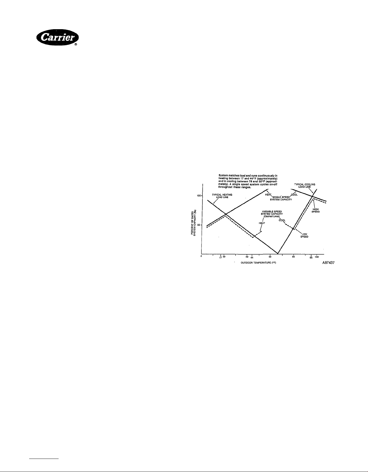
General Operation:
The abflity of the system to control compressor and blower
speeds as described above allows it to adjust its output
capacity to match the varying load requirements of an
installation.
This type of operation results in less on-off cycling (ref. Fig.
1), quieter operation and improved temperature control at
modera:te and low load conditions.
Fig. 1—Variable Speed System Matches Load
STEP 2—Component Functional Description
CONTENTS
Page
38EV, QV Outdoor Units
Main Control Board...............................................................4
Compressor Inverter..............................................................4
Compressors
Outdoor Coil, Suction Thermistor (Tl, T2)
Outdoor Fan Motor/Capacitor
Outdoor Solenoid Expansion Valve (SEV)
High Pressure Switch (HPS)
Low Pressure Switch (EPS)....................................................7
Emergency Stop Switch (ESS)
Crankcase Heater and Switch (CH, CHS)...........................7
40QV Fan Coil, 58SSB Furnace Blower Accessory
Interface Board ....
Blower Controller...................................................................7
Blower Motor
Indoor Solenoid Valve (SEV) . .............................................
Indoor Coil Thermistor (T3)..................................................7
Figs. 2 and 3 shows layout of components in the variable
speed control system. This section will describe each compo
nent and discuss its function in attaining proper system
operation.
..........................................................................6
..........................................................................
..........................................................
..........................
..............................................
..........................
..............................
.......................
...............................................................7
...................
.......................7
................
6
7
7
7
7
4
6
6
Manufacturer reserves the right to discontinue, or change at any time, specifications or designs without notice and without incurring obiigations.
Book| 1 I 1 I 4 I 4 PC 101 Cataiog No. 533-895 Printed in U.S.A. FormSSEV, QV-1SM Pg 1 12-87 Replaces: New
Tab I3al5al2al5a
Page 2
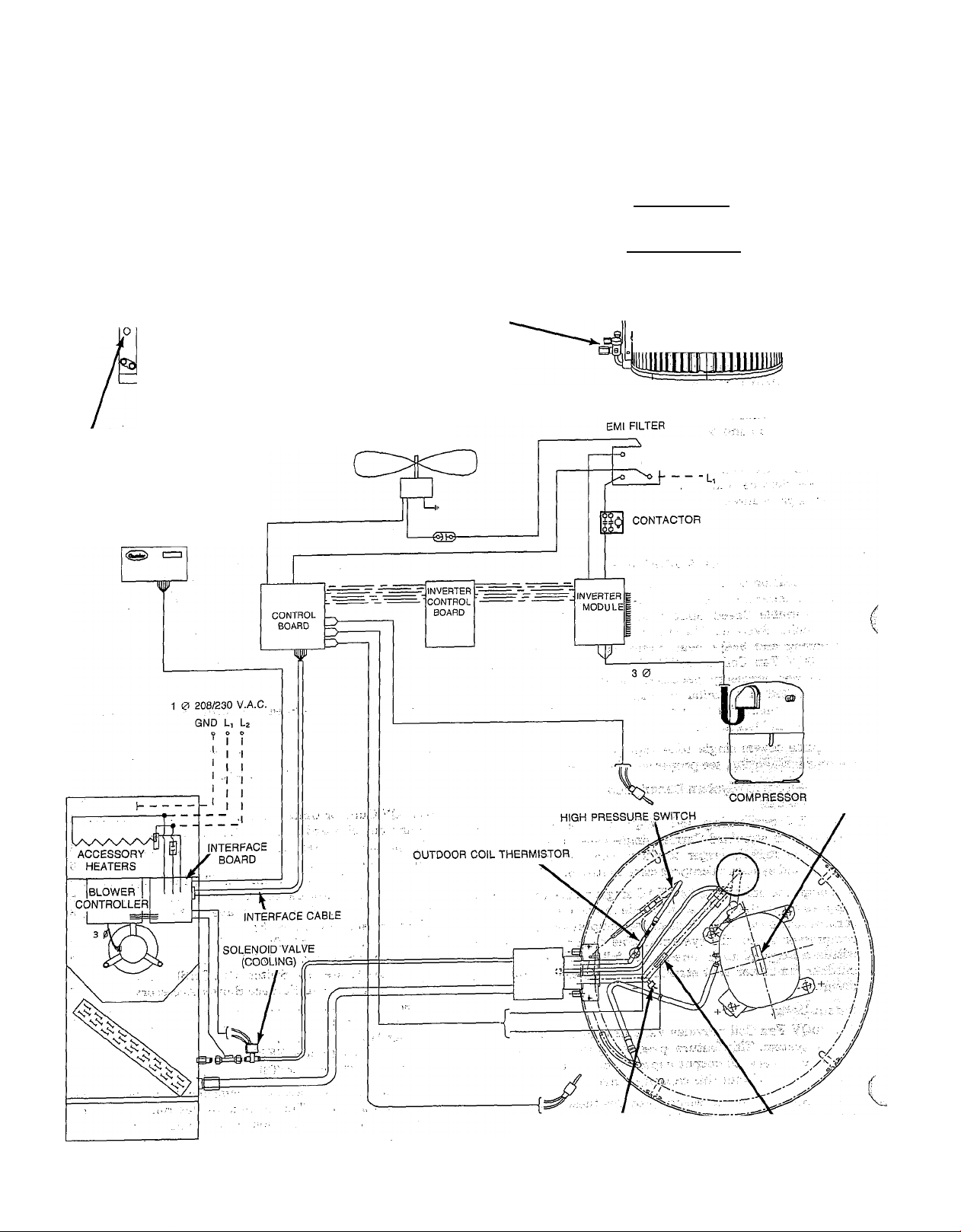
38EV Variable Speed Air Conditioning System
SERVICE VALVES
THERMOSTAT
FAN COIL
40QV024
40QV036
SERVICE VALVES,
SERVICE PORT
OUTDOOR FAN
OUTDOOR UNIT
38EV024
38EV036
&
inrininTlTnili
iMTrifrilTTnW
felinui
™eidemh
N>1
----
°
-----
U
GND , 1 0 208/230 V.A.C.
LOW PRESSURE SWITCH
Fig. 2—Simplified System Schematic
(shown with 40QV Fan Coil)
ESS SWITCH
(036 ONLY)
SUCTION THERMISTOR
A87260
Page 3
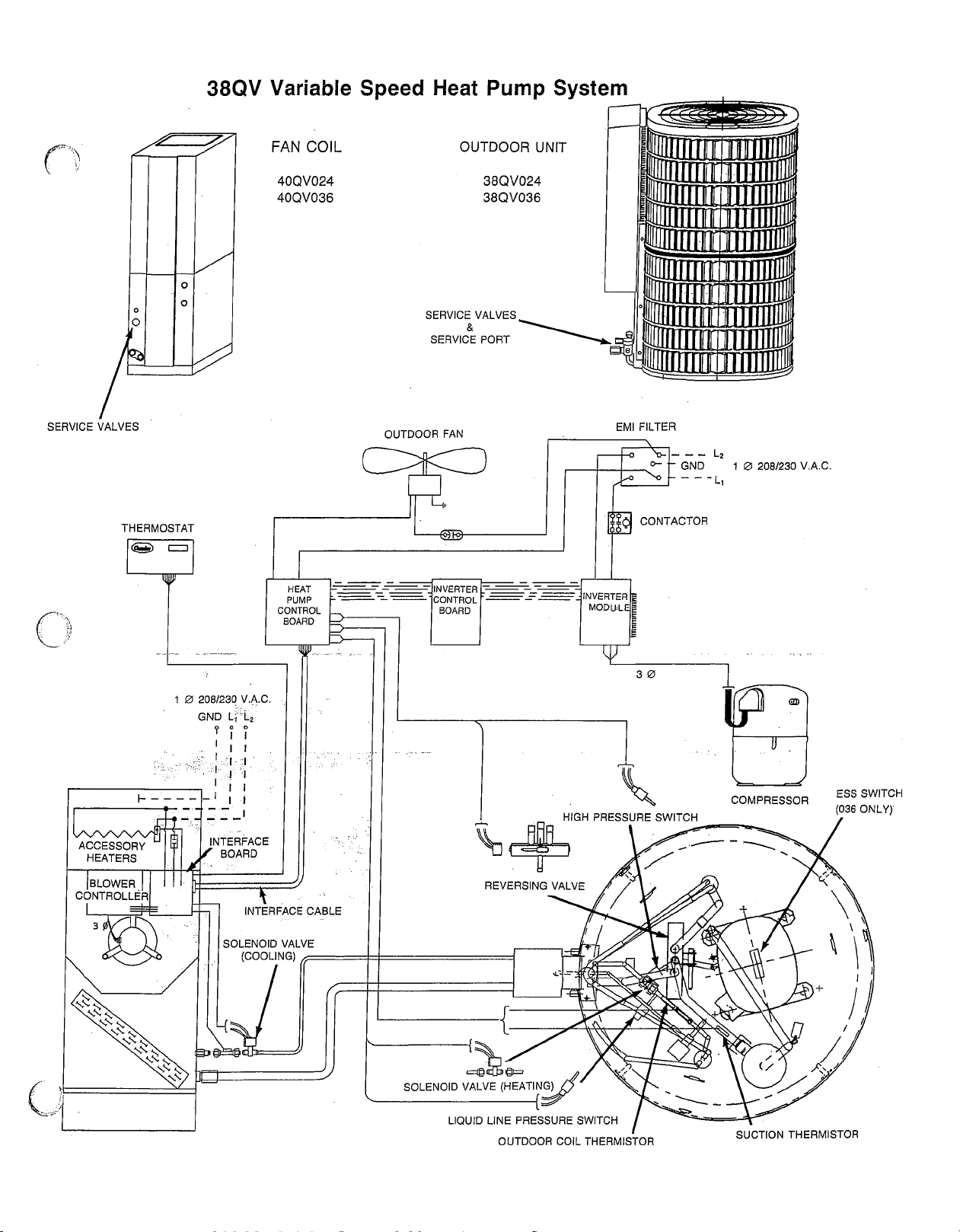
Fig. 3—Simplified System Schematic
(shown with 40QV Fan Coil)
A87215
Page 4
38EV, 38QV Outdoor Unît
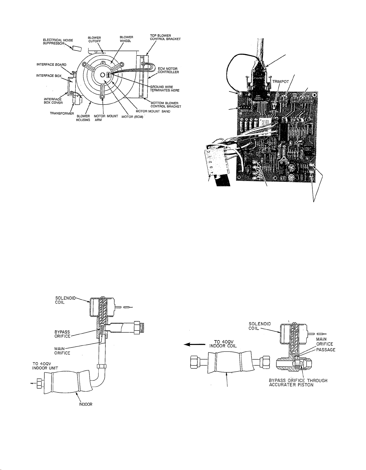
Main Control Board:
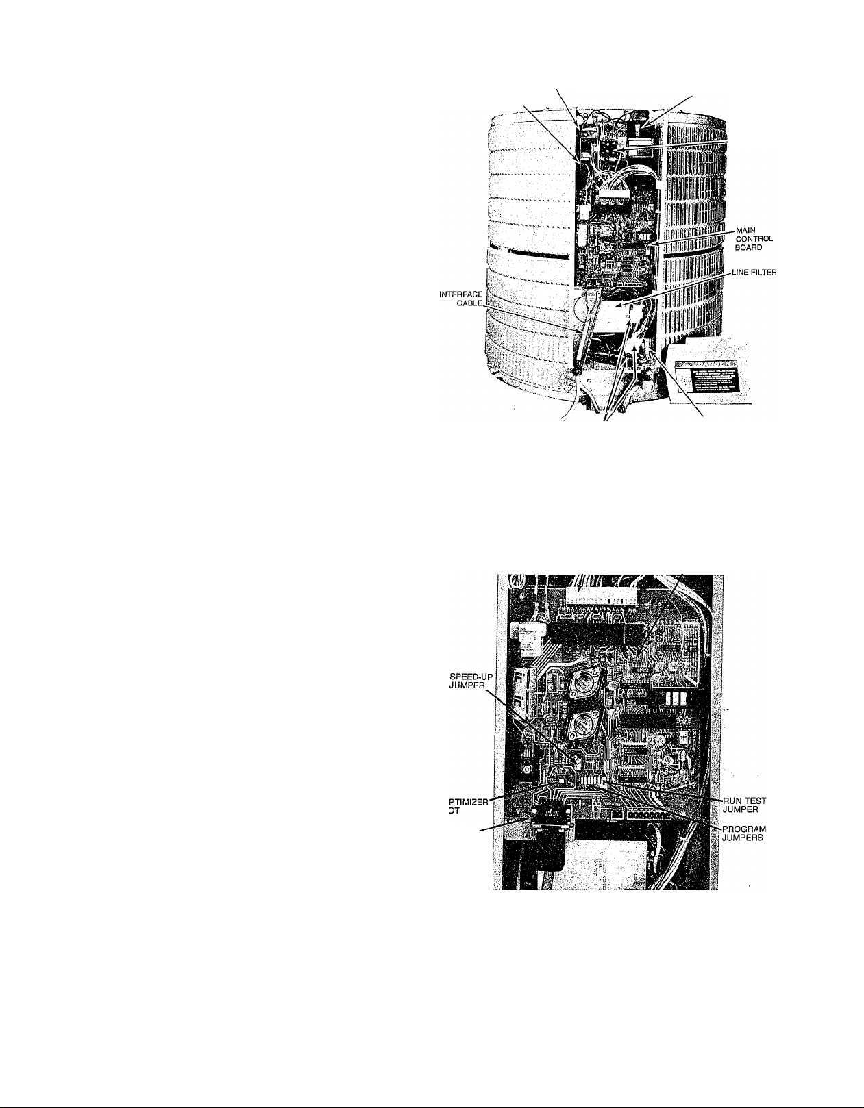
The main control board is located in the front of the 38E V/
QV control box. It is fully visible and serviceable by simply
removing the control box cover, as shovm in Fig. 4. All wir
ing connections for components internal to the unit are at
the top of the board as shown in Fig. 5. Low voltage connec
tions are at thè white 17 pin connector, high voltage (O.D.
fan relay) at the two push on terminals in the upper left. All
connections to the indoor unit aré made through the 15 con
ductor Interface Cable connector located in lower left of the
board.
Thè main "control boárd receives information on system sta
tus from 5 devices (including WT-II thermostat) and uses
it to determine proper control for its 10 outputs. These I/O’s
are listed below: •
Inputs:
1) Thermistor (T2), Suction Line.
2) Thermistor (Tl), O.D. coil (between expansion device
and coil).
3) Thermistor (T3), I.D. coil (between expansion device
and coil).
4) Compressor Inverter (over-current alarm).
5) Thermostat (cool/heat, capacity demand, etc.)
Outputs:
1) Inverter (compressor) speed signal.
2) I.D. Blower Speed Signal (via interface board).
3) O.D. Solenoid Expansion Valve* (refrig, expansion con
trol, heat mode).
4) I.D. Solenoid Expansion Valve (refrig, expansion con
trol, cool model).
5) Main Contactor (inverter/compressor on-off control).
6) O.D. Fan (on-ofif control).
7) Reversing Valve* (on-off control).
8) Aux. Heat (electric or furnace heat on-ofif).
9) On-Board LED (on-off for diagnostics codes, etc.)
10) Thermostat (display of diagnostics codes, etc.)
*38QV Heat Pump Units Only
Compressor Inverter:
NOTE: The following text describes disassembly of the con
trol box for purposes of explaining inverter, coniponent func
tion only. Inverter components are not serviceable, and
shoüld not be removed from the control box.
Serviceable items include only the main control board, con
tactor and fan capacitor.
Failure of any other component requires replacement of the
entire control box. See instructions included with replace
ment control box for this procedure.
The inverter is made up of 6 components, all mounted in the
38EV/QV control box. , ~
With the main system control board and backpanel
removed (3-screws) the inverter board is clearly visible (See
Fig. 6). _ w,, /;
Removal of the inverter board allows a view of the rest of
the inverter components, which are pointed out in Fig. 7.
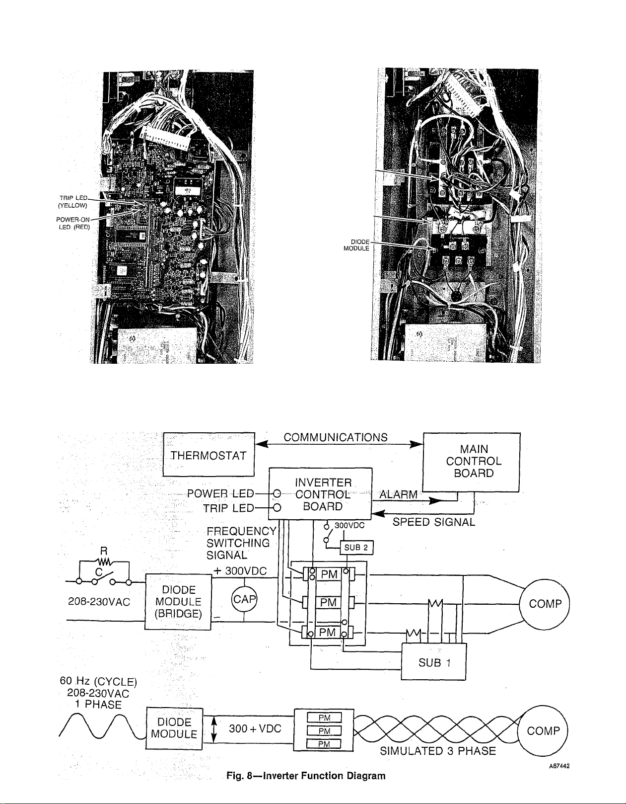
(Refer to Fig. 8) The inverter operates with 208-230VAC,
single-phase input power provided to the Diode Module (or
diode bridge). Here the AG power is converted to high volt
age DC (325V approx.).
The large (black) Smoothing Capacitor in upper right of the
control box is required to Smooth the DC voltage and is at
this 325 VDC potential.
SUB-BOARD it2
SUB-BOARD tn
SMOOTHING CAPACITOR
CONTACTOR
CONTROL BOX-TO-UNIT
CONNECTORS
FAN CAPACITOR
Fig. 4—Control Box, Cover Off
17 PIN DIAGNOSTIC
CONNECTOR LED
INTERFACE
CABLE
CONNECTOR &
RETAINER
LATCH
Fig. 5—Control Board
The DC power is then provided to the Power Modules (3) or
Power Transistors via a buss mounted across all 3 modules.
The power modules drive the 3-phase compressor when the
Inverter Board receives a signal from the main control
board requesting a certain compressor speed. The inverter
board switches each power module on-ofif into a signal simu
lating a single-phase signal. (See Fig. 9A). Each power mod
ule is switched in the same pattern, but 120-deg. out-of
phase from the other two modules, so the total output is in
3-phase form. (See Fig. 9C).
A87438
A87216
Page 5
POWER
MODULES (3)
HEAT SINK
A87440
Fig. 6—Control Board Removed Fig. 7—Inverter Board Removed
38EV/QV COMPRESSOR INVERTER OPERATION
. - .
.... SERIAL ........................................................
........
- -
A87441
..........
Page 6
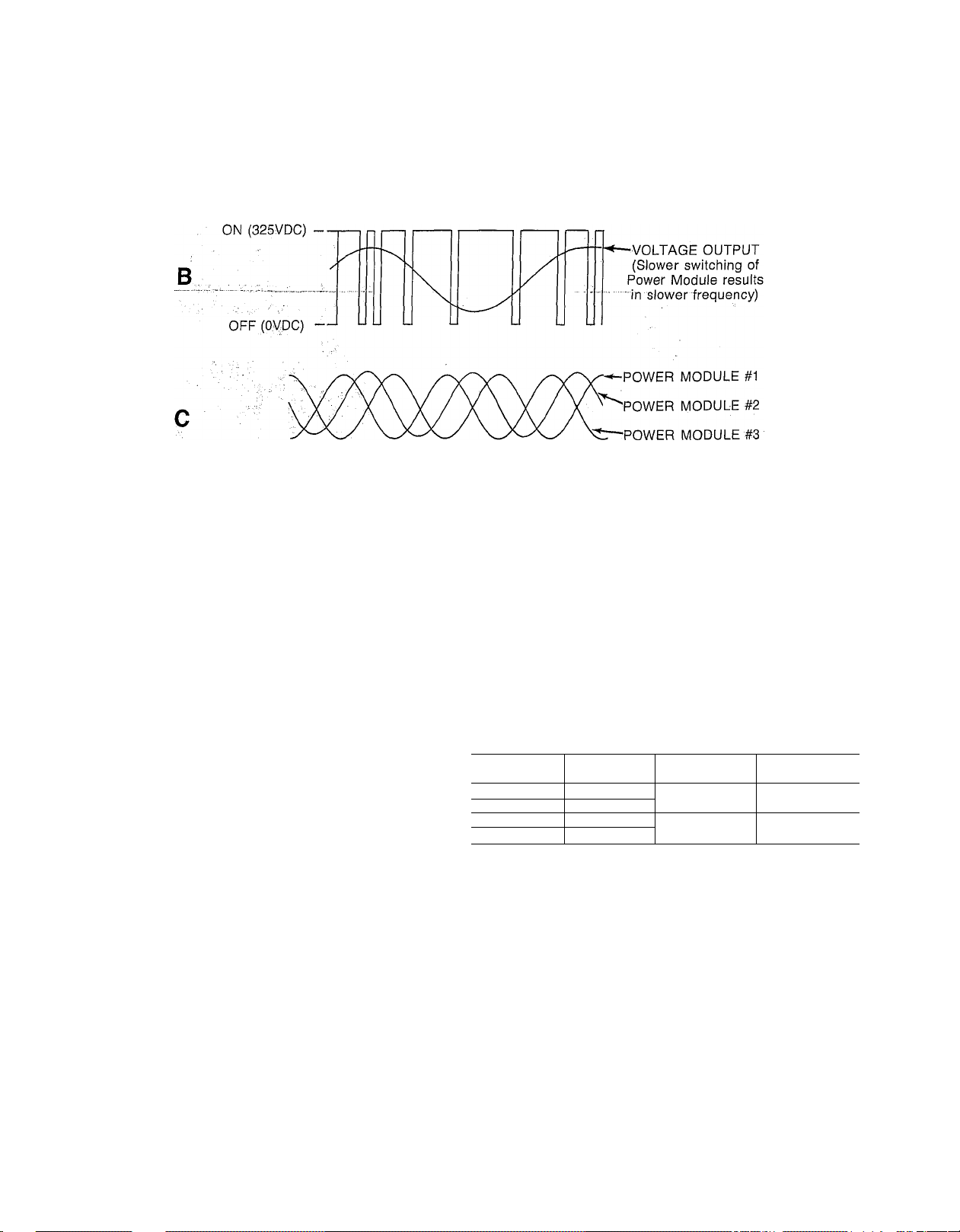
ON (325VDC) —
OFF (OVDC) —
/
\
Fig. 9—Inverter Power Module Switching
VOLTAGE OUTPUT
(Average of ON-OFF
■ voltage)
o
A87443
A change in the speed signal from the main control board
causes thé inverter board to switch the power modules at a
different rate, thus changing the 3-phase output frequency,
and compressor speed. (Ref. Fig..9B),
In summary, the inverter takes a 230V, single-phase, 60 Hz.
frequency input and converts it'to high voltage DC. It then
converts it to 3-phase AC power at frequencies of 30-90 Hz.
to drive the 3-phase compressor at speeds of 1800 to 5400
RPM.
Although other inverter components (shown in Fig. 4) were
not needed in the above'functional description, they are still
necessary to maintain inverter integrity and reliability.
Sub-board #1 is used to suppress electrical noise caused by
power module switching to prevent interference with the
inverter microprocessor. It also contains 2'current loops so
the inverter can monitor its own current output. Sub-board
#2 is an under-voltage protector for the inverter bbardr
Compressors—are of a spedial design to operate reliably
over the 180Ô-540Ô RPM (30-90 Hz. frequency) speed range.
They are driven by a standard design 3-phase motor. ,
—38EV024, 38Qy024 Models—have a reciprocating 'com
pressor with internal PTC heater and internal overload
feature. It has specially hardened valves for high speed
operation, and special oil pump to retedn proper lubrica
tion at low speeds.
Its internal current and temperature sensitive overload
resets automaticaUy when internal compressor motor
temperature drops to a safe level (overloads may require
. .. up to 30 minutes to reset). When an internal overload is
suspected of being open, check by using an ohm-meter
or continuity tester. - -
..:...
■
The internal high Pressure Relief Valve opens at a pres
sure differential of approximately 450-f-50 psig
between suction (low side) and discharge (high side) to
. allow pressure equalization..
See Table 1 for proper oil charge.
—38EV036, 38QV036 Models—have a scroll compressor.
This type of compressor contains no valves, similar to a
rotary type. The “movable” vane osciQates in a cam fash-
ion to force refrigerant around from outer edge to the cen
ter discharge, while compressing it.
The scroll compressor contains no internal overload
devices. Instead, an emergency stop switch (ESS) is
mounted to the top of the compressor (see description
below).
It also requires no high' pressure relief valve. At exces
sive pressure the scroll vane is hfted from its seahng
surface, allowing high tolow'side bypass.
Table 1—Refrigerant and Oil Charge
Unit
Model
38EV024
38QV024 ;
38EV036 : 8.1
38QV036
Charge
R-22(lb)
, 8;5 Sontex2000
9.5
Oil
Type
Calumet RD-15 or
Sunisco 4GS 41/39
Oil Charge (oz)
New/Recharge
( , : 55/51
Thermistors:
Three thermistors are utilized by the main control board to
monitor refrigerant temperatures at locations shown in
Figs. 2, 3 and 10. The same model thermistor is used at all
three locations. Each is mounted in a %6” O.D. tube secured
to the refrigerant hne for improved accuracy and protection
of the device, and then heavily insulated (armaflex tube).
O.D. Fan Motor/Capacitor:
The totally enclosed fan motor is of standard 208-230
single-phase design for single-speed operation. Its related
capacitor, located in lower right of the control box, is also of
standard design.
Outdoor Solenoid Expansion Valve (SEV)—38QV Heat
Pumps Only.
This device is identical to that used at the indoor unit,
except for accurator piston size. Refer to Indoor Solenoid
Expansion Valve Description.
Page 7
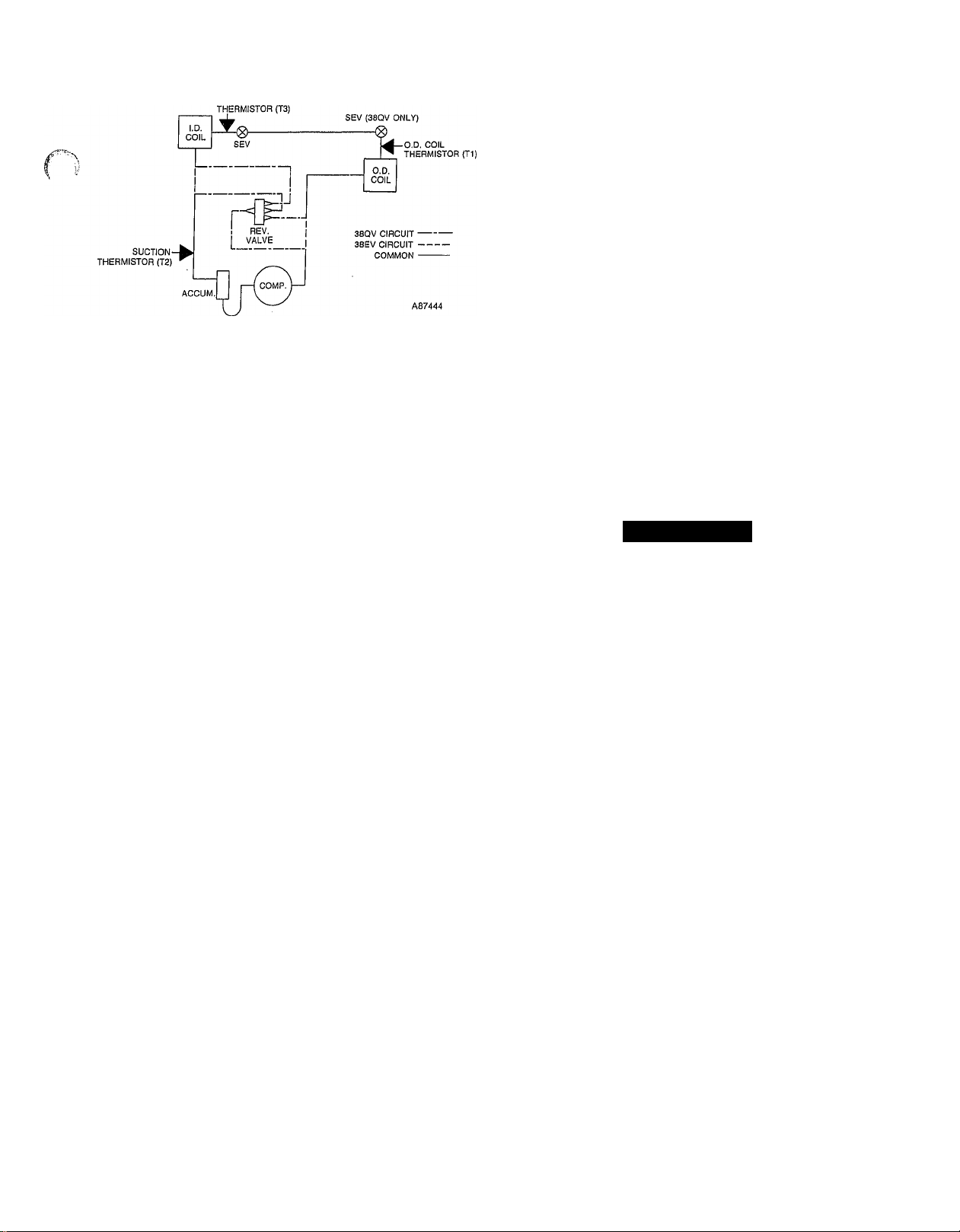
Fig. 10—Thermistor Locations
58SSB Furnace Blower Accessory—Includes the same
motor as the 40QV fan coil. Its controller and interface
board are 115 VAC versions of the fan coil components,
mounted as shown in Fig. 13.
Interface Board—serves three major functions in the
system.
Whenever gas or electric heat is energized, the interface
board takes over control of the blower from the outdoor
unit. It then forces the blower to high heating speed, which
is adjusted at the blower speed trimpot (ref. Fig. 14).
The board also contains the VVTTI thermostat power
supply.
Last of all, it acts as a connection point for input power, and
the control circuit between outdoor unit and indoor compo
nents (i.e., indoor SEV, thermistor, transformer, and blower
motor).
Blower Controller—serves a function similar to the outdoor
unit compressor inverter. It converts single-phase, 60 Hz.
power into a variable frequency output to control blower
motor speed. High and low motor speed settings are adjust
able at a 10-pin connector on the controller.
Blower Motor—is of unique design, containing a permanent
magnet rotor for superior eflBciency.
High Pressure Switch (HPS)—is provided for high pressure
protection of the system. It is located on the hquid line in
38EV units, and the discharge hne in 38QV units, (ref. Figs.
2 and 3). Its setting is 425 (+ -10) psig.
Low Pressure Switch (LPS)—is included to provide loss-ofcharge protection.
(
In 38QV heat pumps the LPS is located in the hquid line
between the outdoor coil and outdoor SEV (ref. Fig. 3). Its
setting is 5 + (+ -3) psig and provides protection in the heat
ing mode.
In 38EV coohng units, the LPS is located in the suction line
between suction service valve and accumulator (ref. Fig. 2).
Its setting is 27 (4--5) psig.
Emergency Stop Switch /EiSSj—Is used only on 38ÉV036
and 38QV036 model units. It is mounted to the top of the
scroU compressor to provide over-temperature protection,
as the scroll has no internal overload. It is located in the
safety electrical circuit in series with LPS and HPS
switches. The ESS is set to open on temperature rise at
265 + -10 deg.F and reclose at 210 + -20 deg.F.
Crankcase Heater and Switch (CH,CHS)—is connected
across the input side of the line filter and operates continu
ously except above the setting of the crankcase heater
switch (70-deg.F) which is located on the liquid hne.
The purpose of the heater is to keep the crankcase warm
during the off cycle and thus prevent dilution of the oil with
refrigerant. This assures good lubrication and prevents loss
of oil from the crankcase during startup. To energize crank
case heater, turn the indoor thermostat to OFF position and
energize electrical disconnect to the outdoor unit. If the elec
trical disconnect switch to the outside unit has been off for
an extended period of time, the crankcase heater should
be always energized for 24 hours before starting the
compressor.
INDOOR UNIT COMPONENT DESCRIPTION
40QV Fan Coils—Are essentially standard Carrier indoor
units with motor replaced by the variable speed motor and
208-230 VAC controller and interface board (ref. Figs. 11
and 12.)
A CAUTION
An extremely hard or sharp blow to the casing or drop
ping the motor may affect motor operation due to mag
net damage.
Indoor SEV Assembly—Is provided with the 38EV or 38QV
outdoor unit. It must be mounted to indoor unit liquid con
nection during installation. The 38EV SEV assembly pro
vides two expansion orifices in parallel; a main orifice, which
is controlled by the solenoid, and a b3q)ass orifice (See
Fig. 15).
The b5qiass orifice is sized to meter refrigerant properly at
low compressor speeds with valve de-energized. At high
Compressor speed, the solenoid is energized, allowing paral
lel flow through a second, main orifice, sized properly for the
additional refrigerant flow needed. At intermediate com
pressor speeds, the solenoid is cycled on-off to control mid
range flow rates.
The 38QV heat pump valve functions in much the same
manner, except the fixed bypass orifice is replaced by a
standard accurator piston. This allows the capability for
non-expanded flow in the reverse direction needed in heat
pumps. This valve, with cutaway, is shown in Figs. 16
and 17. See Table 3 for piston sizes.
The SEV solenoids are energized by a 24 VDC coil, driven
directly by the main control board.
Indoor Coil Thermistor (T3)—Mounted to the SEV assem
bly, it is identical to the outdoor unit thermistors.
STEP 3—Sequence Of Operation
Startup—Once the system is properly installed or serviced,
there are two methods available to start the system and
check operation.
The first method is the “Run Test” function, which is
highly recommended for operational checkout after initial
installation or servicing. The Run Test automatically oper
ates the system in both the heat (including aux. heat) and
cool modes, thus eliminating the need to adjust the thermo
stat a number of times to force system into the desired oper
ating conditions. “Run test” operation is detailed below.
Page 8
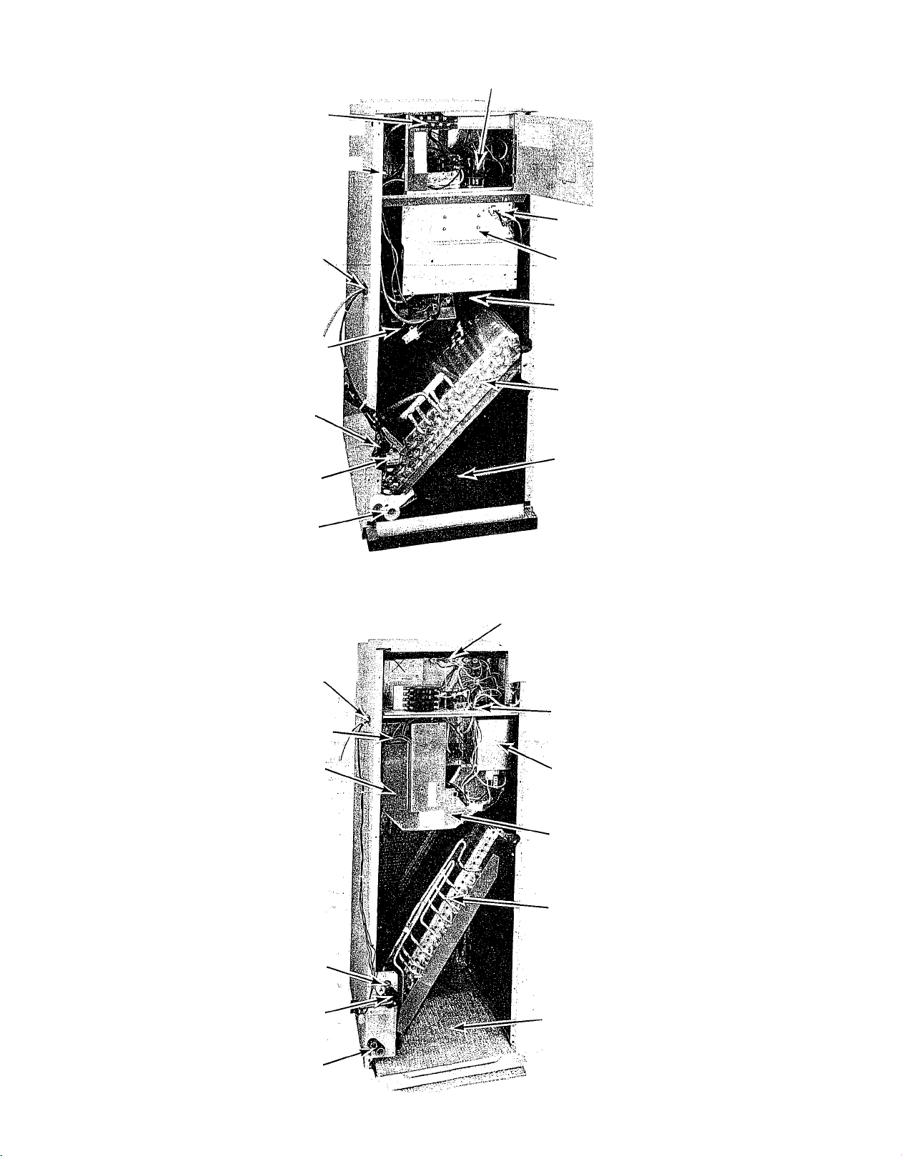
LOW-VOLTAGE
TERMINAL AREA i|
FAN DECK WIRING-^^
PASSAGE HOLE
(HIDDEN)
ACC ELECTRIC HEATER
AND CONTROLS
MOTOR LEADS
OUTDOOR CABLE
ENTRY HOLE
INTERFACE BOX
REFRIGERANT LINE
CONNECTIONS
SEV ASSEMBLY'
CONDENSATE
DRAINS
OUTDOOR CABLE
ENTRY HOLE
ECM MOTOR
CONTROLLER
BLOWER ASSEMBLY
INDOOR COIL
FILTER SECTION
A87445
Fig. 11—40QV024 Fan Coil
ACC. ELECTRIC
HEATER AND CONTROLS
jr LOW-VOLTAGE
TERMINAL AREA
1^'
MOTOR LEADS
ECM MOTOR
CONTROLLER
REFRIGERANT
LINE CONNECTIONS
SEV ASSEMBLY
CONDENSATE
DRAINS
FAN DECK WIRING
PASSAGE HOLE
INTERFACE BOX
BLOWER
ASSEMBLY
INDOOR COIL
FILTER SECTION
A87446
Fig. 12—40QV036 Fan Coil
R
Page 9
ISOLATOR GROMMET
Fig. 13—58SSB Furnace Blower Assembly
A87447
INTERFACE CABLE
GROUND WIRE
SEV/THERMISTOR
CONNECTOR
INTERFACE CABLE
LOW VOLTAGE TERMINAL
BLOCK (TO ACCESSORT
HEATERS OR FURNACE)
THERMOSTAT
TERMINAL BLOCK
TO OUTDOOR
UNIT
LIQUID LINE
CONNECTOR FOR HEATER BOX TRANSFORMER
ACCESSORY OR FURNACE
BLOWER LEADS
„ PR1-2 POWER TO INTERFACE
LI, L2 POWER INPUT PRM,
Fig. 14—Interface Board
CONTROL POWER FROM
INTERFACE BOX
TRANSFORMER
A87448
THERMISTOR
Fig. 15—38EV SEV Cutaway
A87449
INDOOR
THERMISTOR
Fig. 16—38QV SEV Cutaway
A87450
Page 10
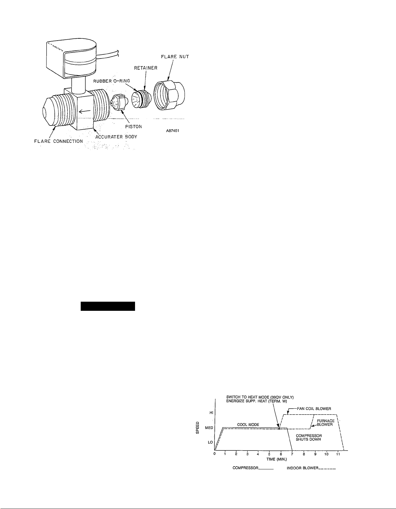
Fig. 17—38QV SEV Parts
The second method involves setting the thermostat setpoint
for a high demand (4-deg.F or more from room temperature)
in the heat or cool mode. To accomplish this, refer to ther
mostat setup instructions, Step 4. This will allow the sys
tem to start and operate normally.
A “Speed-Up” function is available to aid in operational
checkout if the normal startup method is used. The “Speed-
Up” function shortens the delays and timing sequences of
the normal startup routine, and is described in this section.
The system Self-Diagnostic feature (Eef. Troubleshooting,
Step 5) is incorporated in both the Run Test and normal
startup operation.
Run Test-
Initiation—Remove the outdoor unit control box cover, then
apply power to indoor and outdoor units.
A WARNING
High Voltage power is supplied to control box compo
nents immediately upon closure of external main dis
connect. The main contactor is bypassed fqr initi^
charge-up of inverter capacitor (ref. Fig, 8). Electrical
shock or death may result,, ,,
one of the following responses:
a) The unit may not start (Error Codes 3-5,8).
b) The unit may shut down prematurely (Error Codes 9,
10). Compressor and/or indoor fan speed may fluctuate
before shutdown as the system attempts to verify or
clear the problem (Error Codes 11, 14).
c) The unit may complete the Run Test properly, but
flash an Error Code during operation. Some diagnos
tics, such as low cheu-ge indication (Error Code 15), are
designed to warn the serviceman of potential problems
but may not affect system operation.
Manual Checkout During Run Test:
Although the system is equipped with self-diagnostic capa
bilities, it should stül be visually and audibly inspected for
proper installation and operation during the Run Test.
A check list of system operational functions is included
below. Refer to Fig. 18 for the sequence of these functions
and check each item. To complete the list, the Run Test can
be initiated more than once.
a) Verify that compressor and outdoor fan operate with
out excessive vibration of the outdoor unit in its
mounted position.
b) Verify indoor blower operates in both the Cool and
Heat Mode.
c) Verify indoor solenoid expansion valve operates prop
erly by listening closely for valve clicking off-on at
about 3-second intervals.
d) Reversing valve switches off (detected by “woosh”
sound) when unit changes to Heat Mode. This sound
also ensures valve was properly energized for cooling
operation (38QV only). /
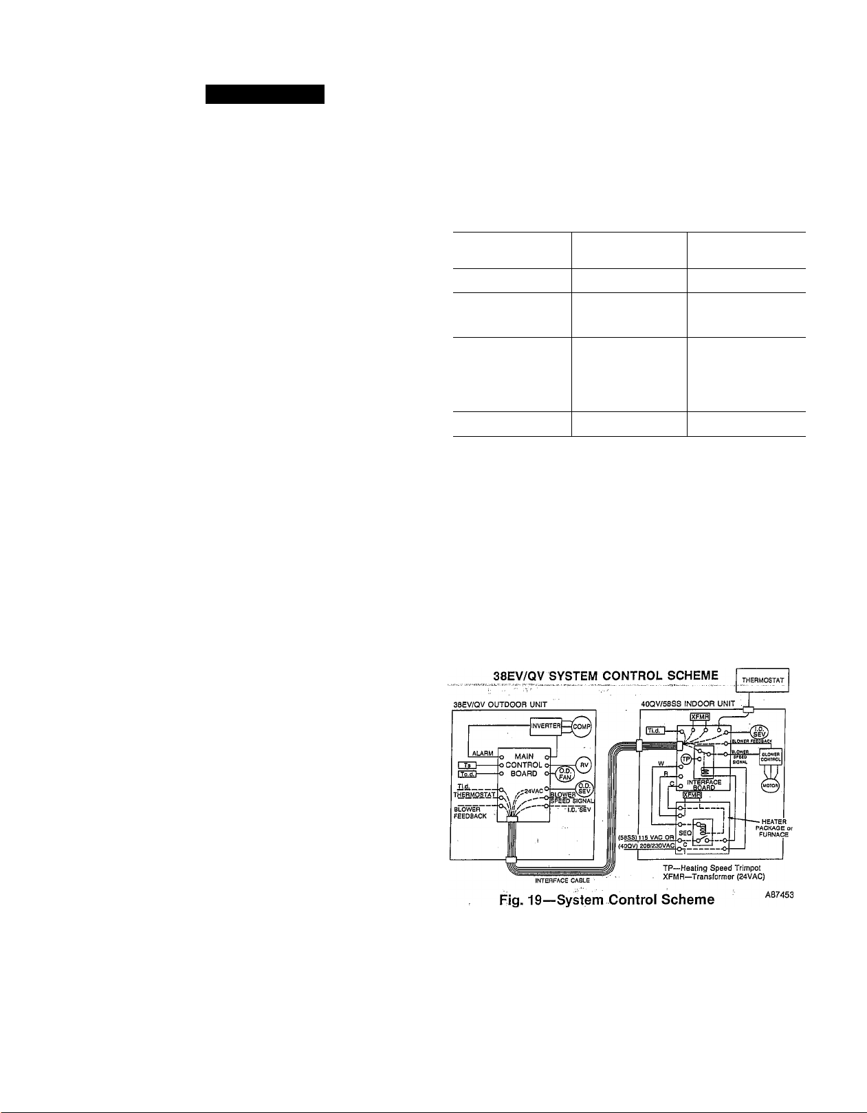
e) Verify that indoor blower speed override for gas or elec
tric heat operates properly (blower jumps from medium
to high speed). This function is necessary to guarantee
full blower speed operation when electric heat or fur
nace is on. (Blower control is different for gas vs. elec
tric heat as shown in Fig. 18).
f) Verify that electric heaters or furnace burners operate.
Once the “Run Test” has completed and the unit, including
auxiliary heat is off, the main control board LED will illumi
nate. When it extinguishes, system can be started normally
by adjusting thermostat.
The Red LED on Main Control Board will illuminate for
approximately 30 seconds, and then extinguish.
To initiate “Run Test” function, remove yellow jumper
(board is labeled “Run Test” as ishowri in Fig. 5). Unit will
start soon after jumper is reinstalled in its proper position
on the board. _ v
Operating Sequence;
In the absence of any diagnosed problems, the system will
operate in the Cool Mode for 7 minutes. It will then switch
to Heat with auxiliary heat on (gas or electric) and immedi
ately ramp the compressor down and off. Auxiliary heat
remains energized for about 3 minutes. See Fig. 18 for a pic
torial of Run Test sequence.
Influence of Diagnostics:
If a problem is diagnosed by the main control board, the
Red LED will flash an error code. Refer to Section 5, “Trou
bleshooting” for interpretation of the flashing code.
The system may, however, react in different ways, depend
ing upon the problem diagnosed. Certain errors wiU cause
A87452
Fig. 18—Run Test Sequence
Page 11
(J
A WARNING
Unit is capable of restarting on normal thermostat
demand soon after Run Test is completed. Personal
injury can result.
Normal System Startup Sequence
Apply power to indoor units via main disconnect switches.
If outdoor unit control box cover is removed, main control
board LED wiU light and extinguish after 30 seconds.
Thermostat will display HPOO (for 38QV units) or ACOO (for
38EV units).
Set up thermostat in heat, cool or automatic mode for room
temperature desired (Ref. Thermostat Operation, Trouble
shooting Section 4).
Thermostat setpoint must be 2-deg.F or more away from
room temperature for the system to initiate a startup.
(Room temperature can be displayed on thermostat by
pressing both heat setpoint adjustment buttons to right of
display simultaneously).
Startup Sequence
NOTE: Startup delays and sequence times can be shortened
for system checkout by initiating “Speed-Up” jumper,
described below.
a) Time Guard-
Normal Ambient Startup—Mter applying power and/
or adjusting thermostat setpoint, the system will
undergo a 5-minute delay before starting. This will also
occur any time the system cycles off normally, to pre
vent unnecessary on-off cycling.
Low Ambient, Initial Startup—When outdoor tempera
tures are near or below 20-deg.F, the system will
undergo a 26-minute delay bn initial power-up only.
This allows the crankcase heater to at least partially
warm up compressor before startup.
Siartop—Compressor wffl start and ramp up to low
speed, outdoor fan wffl come on. Indoor blower will
start in a similar manner to compressor, 30 seconds
later.
b) Low Speed LocA-Iti—After starting, the' unit will lock
in at low speed for a period of 8 minutes. This is done
for the following reasons:
1. System self-diagnostics wffl monitor system condi-
tionis during this period to verify proper system
operation.
2. Allows indoor blower time to circulate and slowly
mix possibly cold ductwork air with room air, thus
avoiding erratic speed fluctuations due to unstable
thermostat readings.
c) Transition to Normal Control—li the thermostat is sat
isfied during the Srminute period at low speed, the sys
tem wffl remain at low speed for 4 more minutes and
then shut down. If not, it wffl speed up depending upon
thermostat demand. The startup sequence is complete.
“Speed-Up” Function
The “Speed-Up" jumper is a yellow jumper, similar to the
“Run Test” jumper. It’s located on the outdoor unit main
control board next to the label “Speed-Up” (ref. Fig. 5). The
function is initiated by removing and reinstalling the
jumper during the sequence period you want to eliminate.
For instance, if you want to ehminate the time guard period
before startup, wait for the LED to extinguish after powerup. Then pull and reinstall the “Speed-Up” jumper. This
wffl shorten the respective period, (i.e., 5 minutes down to 2
minutes for the normal time guard, or 20 minutes down to 4
minutes for low ambient initial startup).
If the jumper is pulled and reinstalled during a sequence
period listed in Table 2, it wffl shorten that period as indi
cated. The speed-up function will then cancel automatically
when the next event listed in the table occurs. To shorten
subsequent sequence periods, the jumper must be initiated
again.
Table 2—Speed-Up Function
Initiate The
Jumper During
This Period
—Prestart
Time Guard
—Low Speed
Lock in At
Startup
— Between Defrost
Periods (Beiow
32-Deg.F
Ambient)
—During Defrost 4-10 Min.-
*Low Ambient Initial Startup
Period Wiil
Shorten From
Normal- to Speed-Up
5 Min.—2 min.
OR* 20 Min.—4 Min.
8 Min.—
40-50 Seconds
45 Min.—4-5 Min.
(1st Defrost)
30 Min.-4 Mrs.3-24 Min.
(Subsequent
Defrosts)
24 Sec-1 Min.
Speed-Up Function
Will Cancel
When
Compressor Starts
Compressor Begins
Ramping Above
Low Speed, Or
Shuts Down
Unit Initiates
A Defrost
Defrost Termination
Cooling Operation
Compressor—
During normal operation, the compressor speed will vary,
based on thermostat demand, from 2200 RPM at low speed
to 5000 RPM at high speed.
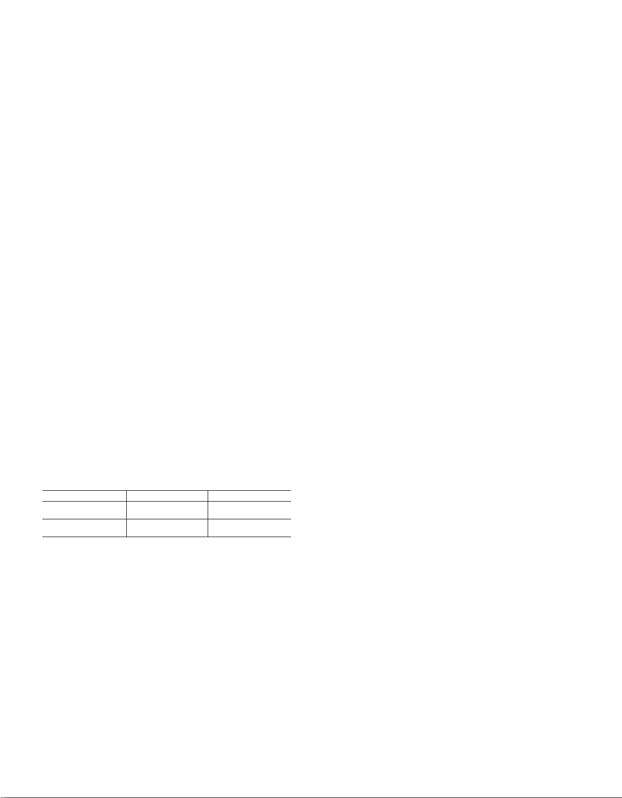
Indoor Blower-
Blower speed (or airflow) wffl “track” or follow compressor
speed; i.e., when the compressor is at low speed, so is the
blower. If the compressor ramps^oTiigh.speed, the blower
ramps to high speed simultaneously. This speed signal is
sent from the outdoor unit main control board, through the
indoor unit interface board to the blower controller. (See
Fig. 19).
Outdoor Fan—
The outdoor fan cycles on-off with the compressor.
Solenoid Expansion Valves (SEV)—
In the cooling mode only, the SEV at the indoor unit is oper
ated. SEV operation “tracks” or follows compressor speed
directly. At low compressor speed operation, the solenoid
remains off and aU refrigerant flow is directed through a
bypass orifice in the valve body (38EV systems). In 38QV
systems, the bypass orifice is located in the accurator piston
(Ref. Component Description, Section 3). At high compres-
Page 12
sor speed, the solenoid is energized on continuously, allow
ing the extra refrigerant flow required through a second oriflce in parallel to the bypass orifice. At intermediate com
pressor speeds, the SEV is cycled on-off at different rates,
depending upon compressor speed. This rate is based on a
5-secpnd on-off period, with the on-time increasing (with
compressor speed) from zero (at low speed) to the full five
seconds on (i.e., continuous on) at high speed. For instance,
at lower speeds, the SEV is on 1 second, off 4 seconds; at
medium speed, on 2.5 seconds, off 2.5 seconds, and so on.
Proper vsllve operation can be checked by listening closely
for the “clicking’’ at the indoor SEV during intermediate
speed operation. - --—
The system will cycle on-off at low speeds at moderate^ (75-
deg.F) outdoor temperatures. It will operate continuously at
increasingly higher speeds as outdoor temperatures
increase.
Heating Operation—38QV Systems Heat Pump
Heat pump operation is executed in the same manner as in
the coohng mode. Indoor blower speed and SEV control
“track” or follow compressor speed directly. However, in
the heat mode, only the outdoor unit SEV is operated. It is
cycled in the same pattern as cool mode control, except
cycling on-time is shortened at colder ambients, (i.e. At low
ambients, the SEV may also be cycling on-off rather than
remaining full on when the unit is at high speed).
The system will cycle on-off at low speeds during normal
operation at moderate (50-deg.F) outdoor temperatures. It
will operate continuously at increasingly higher speeds as
outdoor temperatures drop.
When outdoor temperatures drop to a point where supple
mentary heat is required, dr the optimizer function is ena
bled, electric or gas heat is initiated. Electric heat and
furnace operation are described in the following sections.
Table 3—38QV Piston Sizes
UNIT
38QV024
, - -•
38QV036 ,
Electric Heat Control—(38EV and 38QV ¡Systems)
Electric heat is initiated and controlled by energizing “W”
in the same manner as in standard systems. However, since
the variable speed blower heeds a speed input signal to oper
ate, blower control is considerably different.
Blower Control—In.=a standard 'heat package, energising
‘‘W)’’ energizes the heater sequencer(s). When this is done,
the ian relay is b3^assed-by 230V power to drive the blower
directly. Therefore, if the fan relay is faulty, the blower still
operates for safe electric heat operation.
40QV Fan Coil Units operate in a similar manner (Ref. Wir
ing Diagrams). However, instead of operating the blower
directly, this ■'230VAC power is apphed to the interface
board at terminals C and 1 (see Figs. 14 and 19). When these
terhiinals are energized by the electric heat sequencer, the
interface board relay breaks the speed signal connection
from the outdoor unit and allows the interface board to
drive the board at a speed set by the adjustable pot on the
board. ; '
LOCATION
Outdoor
. . '„ Outdoor ,,
Indoor
. Indoor
...............
. 52
-----
■ PISTON#
42
49
63
When the electric heat (“W”) is cycled off, normal sequencer
operation retains blower control from the interface board
until the heaters cool down. When terminals C and 1 are de
energized by heater package, blower control reverts back to
the outdoor main control board.
Supplemental (2nd Stage) Heat—(38QV Heat Pump/40QV
Fan Coil Systems Only)
Supplemental heat is required when the outdoor tempera
ture drops too low for the heat pump to handle the load
alone. At this point, the system begins cycling electric heat,
in addition to continuing full speed heat pump operation.
This is done by energizing heater package terminal “W.”
The heaters and blowers are controlled as described above.
A change in blower speed when the interface board takes
over control may not be noticeable, since the outdoor unit is
already operating it at high speed.
It may be noticeable if the blower heating speed trimpot is
adjusted below its maximum setting.
Heating Operation—(38EV Cooling Systems) and
Emergency Heat—(38QV Heat Pump Systems)
Electric or gas heat is operated directly on thermostat
demand on 38EV systems or whenever the 38QV outdoor
unit operation is locked out due to a diagnostic problem.
The blower is controlled by the interface board as described
above. However, since the blower is not being operated by
the outdoor unit during electric heat off cycles, the blower
will cycle fuU-on-off similar to standard systems.
NOTE: Malfunction of certain electronic control compo
nents can cause lack of Automatic Emergency Heat initia
tion. See Service & Maintenance section for corrective
servicing procedures.
The 58SSB furnace will operate as described in the litera
ture provided with it. The only difference is control of the
variable speed blower. The standard 58SSB furnace
bypasses its fan relay to lock-in blower operation when the
burner is on, just like an electric heat package.
The variable speed blower package switches blower control
to its interface board when “W” is energized, in the same
manner as described above for “Electric Heat Control.”
(The furnace interface board design is identical to that for
the 40QV fan coil, except it is a il5VAC yersioh)/
The blower will remain off for 2r3 minutes while the burner
ignites and warms the heat exchanger. The blower wUl then
start, and ramp to low speed for a short period before going
to full speed. 'When “W” is de-energized, the blower will
stay on for a short period to use the remaining heat from
theexchanger.
Supplemental (2nd Stage) and Optimizer Control—(38QV
Heat Pump/58SSB Furnace Systems)
Unlike fan coil operation, the furnace wiU not operate simul
taneously with the heat pump. Therefore, whenever the out
door temperature drops to where the heat pump cem no
longer match the load, or the optimizer setpoint is reached,
the heat pump wfll shut down when. furnace startup is
requested (“W” is energized). At this point, the heat pump
wfll also shut down the indoor blower (except if ,the thermo
stat is in the fan-on position). The normal furnace delay of
2-3 minutes wfll then pass before the blower is cycled back
on, to allow the heat exchanger to heat up. Once the thermo
stat is satisfied by the furnace, it will cycle off. Operation
wfll alternate between furnace and heat pump, until either
the heat pump can handle the entire load, or the optimizer
setpoint is reached. If the optimizer setpoint is reached, the
heat pump wfll be locked out (a minimum of two hours) and
the furnace will cycle directly on thermostat demand.
I
Page 13
Adaptive Defrost—
38QV Heat Pump Systems utilize an adaptive defrost con
trol which clears the coil of frost only when necessary.
•r ■■
Based on coil conditions and outdoor temperature, the time
between defrosts is adjusted between 30 minutes and four
hours, as described below.
Between Defrost Period Calculation-
Defrost monitoring is begun when the O.D. coil thermistor
temperature drops below 32 degrees F. The first defrost will
occur 45 minutes later.
When the unit is ready to defrost, the pre-defrost O.D. coil
thermistor temperature (frosted coU) is memorized, and thè
unit then switches to defrost. A short time after defrost is
completed, a post-defrost thermistor temperature (clear coU)
is memorized.
The after-defrost (clear cod) temperature is used to estimate
outdoor temperature and the optimum pre-to-post defrost
coil temperature change (i.e. frosted coil vs. clear coU
temperature).
The time period to the next defrost is then determined by:
a) If defrost time was less than 5 minutes, add 30 minutes
to previous period.
b) If defrost time was maximum (10 minutes), and O.D.
con temperature at termination was:
—more than 45 degrees F, divide previous period in
half.
—less than 45 degrees F, next period will be 30 min
utes.
c) If defrost time was greater than five and less than 10
minutes, the new time is calculated by:
. . , optimum temperature change *
previous peno x actual post-defr. temp..minus pre-defrost temp.
*The new period calculated by this method cannot be less
than half, or more than double the previous period.
Other Limitations:
Maximum period between defrosts is 4 hours.
Minimum period between defrosts is 30 minutes, except:
The initial defirost after coming out of optimizer mode will
occur 15 minutes after startup.
Defrost Sequence—
When a defrost is initiated, compressor speed is dropped to
medium speed. This is done to mininiize shock to the com
pressor. The reversing valve and heat (terminal “W”) relays
are energized, the outdoor fan relay de-energized, and com
pressor then ramped to full speed for a rapid defrost.
Defrost is terminated on any of the following occurrences:
a) O.D. coil thermistor rises to 80 degrees F (when out
door temperature is above 10 degrees F).
b) O.D. coil thermistor rises to 60 degrees F (when out
door temperature is below 10 degrees F).
c) 10-Miuute maximum defrost period.
The system then ramps down to medium speed, returns to
heat mode, and returns to the pre-defrost speed.
Heat/Cool/Auto Control-
This thermostat function controls as in standard systems.
Heat or cool operation may be requested separately. The
“Auto” position allows the' system to switch between these
two modes automatically as required to satisfy thermostat
setpoint demand.
Fan-On/Auto-
With the fan-auto mode selected, the indoor blower will
•HP’OBQV)
\ / \ / \ /
•AC’(38EV).
■HP
00
z' \
NORMAL POWER-UP IMPROPER
Fig. 20-VVT-ll MST Thermostat
--------------------------------------
It
—1
65 HP
56 ;; 56
CONFIGURATION
/
---------------
1 lO'O oii—
^OWER HEAT
SETPOINT
COOL
N
ON I OFF I
68 69 70 71 72 76 77 78 79
4 ’HP' or 'AC:.
\
•66 HP
-HEAT
' \
SETPOINT
ROOM TEMPERATURE
05
SYSTEM
DIAGNOSTIC
ERROR CODE
A87454
cycle on-ofil with the outdoor unit and/or the electric/gas
indoor unit.
The fan-on mode will keep the indoor blower operating at all
times. The blower will operate at low speed during systemoff intervals.
STEP 4 VVT-II Thermostat Startup/Troubleshooting
The MST-04 or MST-16 thermostat consists of a printed cir
cuit board, a connector board, and a wall mounted case.
A thermostat software revision of 6.7 or higher is required.
AU wiring connections to the thermostat are made to the
connector board. .
Mount the thermostat as described in 38EV or 38QV out
door unit installation instructions, or follow the Installation
Instructions included with each control. Thermostat must
be wired as shown in Figs.. 36 and 37.
Fig. 20 shows front view of the VVT-II MST thermostat.
Start-Up Procedure:
Close indoor main disconnect.
Normal Display—The thermostat will. display HPOO (for
38QV systems), ACOO (for 38EV systems), or 4 zeros, then
switch to the normal heating/cooiing setpoint as shown.
Blinking Display—If the thermostat display blinks on .and
off or is erratic, it is an indication that a wiring connection
is not correct, or that the thermostat is not receiving ade
quate power. Check the wiring connections and the supply
voltage (22VAC rninimum) at terminals SEC-1 and SEC-2
on the interface board. Make certain the thermostat ribbon
cable has been inserted into the connector board correctly.
Display Four Zeros—If the display shows four zeros upon
power-up, and then displays “HF-11,” it indicates that the
thermostat is currently configured for a multiple-zone sys
tem. It must be reset for single-zone control.
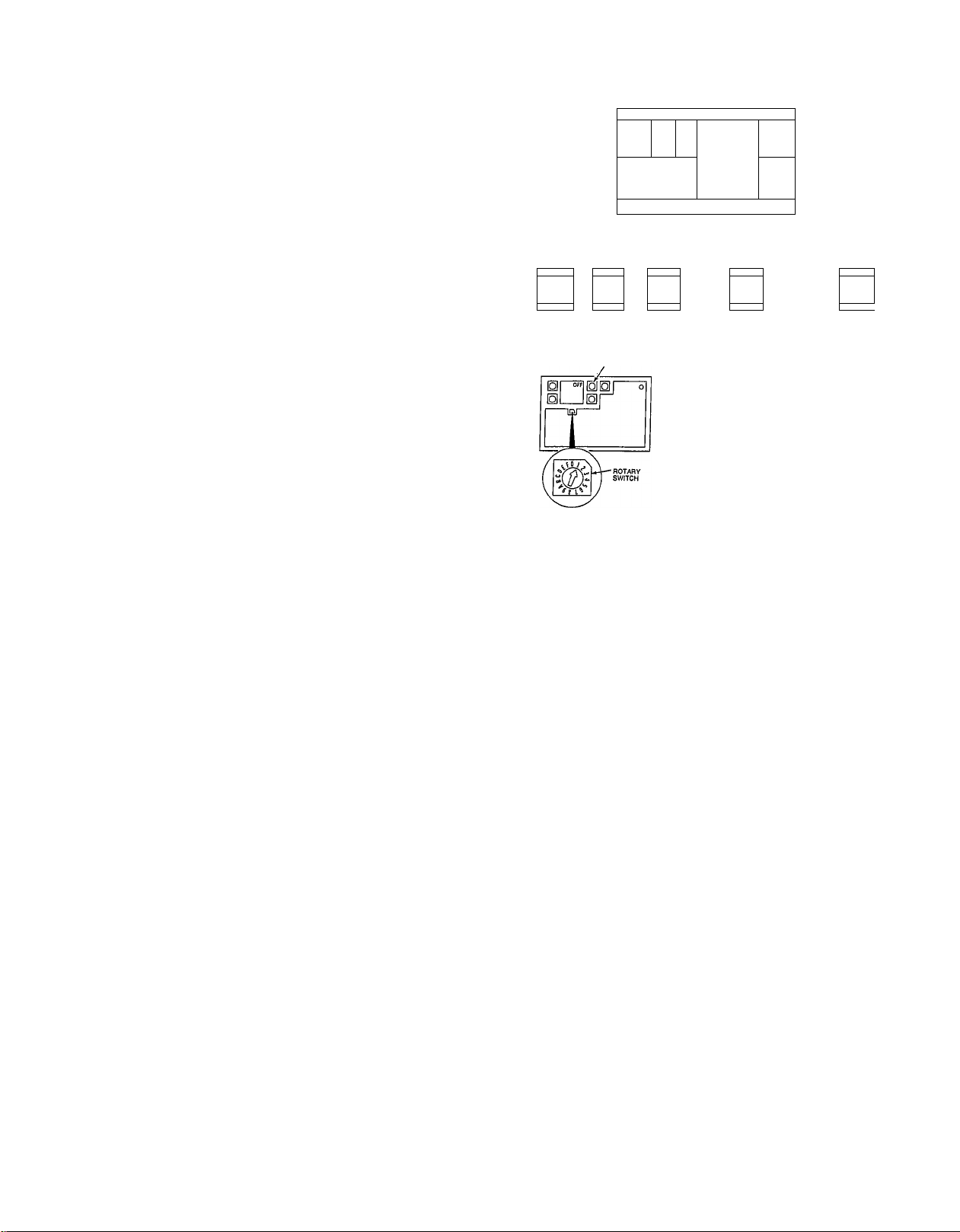
Setting Thermostat For Single-Zone Control—
To correct the configuration, set the rotary switch to posi
tion #1 (ref. Fig. 20). A number and “ON” or “OFF” will
V /
N
Page 14

appear on the display. Press either of the right (“Heat”)
setpoint buttons to change the display to “OFF.” This is
the indication that the thermostat is now correctly set for
single-zone control. Now adjust the displayed number to
“2” by pressing the cool setpoint buttons; the lower one to
decrease the number, upper one to increase. Return the
rotary switch to position #0 and press any setpoint button
to display the normal setpoints.
Adjust Heating/Cooling Setpoints—The setpoints for both
heating and coohng can be easily adjusted by pressing the
setpoint buttons as shown.
Installer Adjustable_Fe Clock Option—Each
thermostat is equipped with a buüt-in instruction manual
which explains the various installer adjustable features and
how to set the time clock.
FoUow each page of the manual to configure the thermostat
based on the application. Always set the “Local Set-back
Control” to ON.
For single-zone control applications, the following features
wül have no effect on the thermostat operation and can be
disregarded at the time of installation:
#6—Duct Temperature Sensor Calibration
#7—Max Damper Position/Min Ventilation Position
#C—System Demand
#D—Communication Test #E—Supplemental Heat
Error Codes—3ie displayed as HF, SF, HP or AC followed
by a two digit number (ref. Fig. 20.) An HF or SF code
indicates a thermostat malfunction (see Thermostat Trou
bleshooting, below). A HP or AC code indicates a system
diagnostic malfunction (see System Troubleshooting,
Section 5).
Set-Back Feature—li the homeowner desires to use the set
back feature, remove the “set-back override jumper” from
the connector board at the back of the thermostat.
Operation—When an “OFF” time occurs, the thermostat
displays the word “SETBACK” and the highest cooRng and
lowest heating setpoints. When an “ON” time occurs the
thermostat returns to the last setpoints that were displayed
before set-back.
Overriding Set-Back—During set-back the heating'or cool
ing set-back Setpoint can be manually 'overridden by adjust
ing the setpoint through the use of the setpoint buttons.
The setpoint selected becomes the new comfort setpoint
that the thermostat uses when the next “OÑ” time occurs.
When the set-back setpdiiit is overridden the comfort
setpoint chosen remains displayed until the next “OFF”
time occurs; unless the' user manually adjusts the setpoint
back to the set-back setpoint; ;
Programming Set-Back—Follow the built-in thermostat
instruction mandai (behind front cover) to program the ON/
OFF times for set-back operation (and for programming the
electronic time clock). ■ , - .
Set-Back Programming Tips—If it is desirable for a particu
lar period to be in set back coiitinuóuály do not enter any
ON/OFF times for that period;
If it is desirable, for a particular period to be in the comfort
rnode continuoúsíy enter an ON time that is the same as an
OFF time.
Heating/Cooling Cycles—The thermostat should be set to
energize a heating cycle and a cooling cycle. Check to make
certain the 38EV or 38QV system operates properly.
“HEAT,” “COOL,” or “FAN” may be shown in the lower
left corner of the thermostat display depending on the sta
tus of the system. The 38EV or 38QV system controls to
1.5-deg.F from setpoint in both heat and cool modes. It will
start-up at 1.5 deg.F from setpoint (minimum run time is 12
minutes), and cycle off based on rate of room temperature
change (ref. Fig. 20).
VVI-ll Thermostat Troubleshooting
Hardware Failures—HF-11 or HF-12. The thermostat is not
properly configured for single-zone control application.
Make certain that “OFF” is displayed when the rotary
switcMs set to position #1.
HF-14, HF-15, or HF-16. There is a failure in the electronic
circuitry on the thermostat. Replace the thermostat circuit
board.
HF-13. The thermostat room temperature sensor is reading
out of its normal range ... 30 to 180 F. (Ref. thermostat
instructions).
Check the room temperature sensor to make sure that it is
physically intact.
Attempt to calibrate the room temperature sensor by fol
lowing the built-in instruction manual. If cahbration is not
possible, replace the thermostat circuit board.
Storage Failures—The thermostat continuously checks its
memory to make certain that stored information is valid. If
information is ever determined to be invalid an error code of
“SF” followed by a number is displayed.
When an “SF” error is displayed, the thermostat will also
use a safe, substitute value appropriate to the particular
code. (See instructions included with thermostat.)
To Clear An “SF” Error—FoUow the buUt-in thermostat
manual to find the correct rotary switch position and reset
the desired setting. Then return the rotary switch back to
position #0.
Time Clock—The time clock should be accurate to within 10
minutes per year. During a power faUure, the time wiU be
maintained for a minimum of 8 hours, after which it may be
necessary to reset the clock, (Ref. thermostat instructions).
If the clock is not keeping accurate time, m^e certain the
power has not been off for over 8 hours. If it has not, then
replace the thermostat.
Set-Back—If the thermostat never goes into set-back make
certain: '
The set-back override jumper has been removed from the
connector board. ,
The thermostat hasn’t been programmed to be continuously
in the comfort mode.
The thermostat is set for the proper time of day.
If the thermostat never comes out of set-back make certain:
A set-back On/Off program has been entered.
The thermostat is set for the proper time of day.
STEPS System Troubleshooting
TABLE OF CONTENTS
Self-Diagnostics—Description
Diagnostic Error Codes Page
Error Codes 3, 4—Outdoor Coil, Suction
Thermistor Failure
Error Code 5—Indoor Coil Thermistor FaUure
Error Code 8—Locked Compressor Rotor
Error Code 9—Overcurrent Trip
Error Code 10—Contactor Control FaUure.................
.......................................................
..........
...................
............................ .22-23
.16-17
18-19
20-21
24-25
Page 15
Error Code 11—Reversing Valve Failure
Error Code 14—Indoor Coil Freeze
Error Code 15—Low Refrigerant Charge
...................
................................
..................
29-31
26-27
28
System Malfunctions with No Error Code
No LED on power-up.....................................................32-33
No Indoor Blower Operation........................................34-35
Electric/Gas Heat Failure..............................................36-37
Miscellaneous Malfunctions
..............................................
39
BEFORE TROUBLESHOOTING THE SYSTEM
This troubleshooting guide covers all components of the
38EV/QV variable speed system, including outdoor and
indoor units.
See previous section for thermostat troubleshooting. (Ther
mostat Error Codes HF and SF).
A WARNING
High voltage (300VDC) circuit remains energized after
main disconnect is opened. Normal capacitive discharge
time is ten (10) minutes, but this period may be
extended indefinitely by component failure. Before
servicing, always check with D.C. voltmeter between
contactor terminal #23 (violet wire) and ground. Always
reinstall safety shield in top of control box after servic
ing. Electrical shock can cause personal injury or death.
Before replacing components to correct a system malfunc
tion, always inspect circuit for damaged or oorroded wiring.
Connectors should be inspected for improper mating. They
should then be unplugged and examined for corrosion, dam
age or incomplete terrhinal insertion. This procedure is espe
cially required when a system malfunction is intermittent
(does not occur consistently).
Clean and/or repair wiring as required. A special accessory
terminal kit (Carrier Service Part No. 38QV660001) includ
ing terminal extraction tools is available through your local,
distributor.
Use high quality multimeter for troubleshooting electronic
devices in this system.
Self-Diagnostic Error Codes—
Error codes are indicated at an LED located on the outdoor
unit main control board (Ref. Fig. 5), and on the indoor ther
mostat display (Ref. Fig. 20).
Control board LED error codes are shown as a series of %
second on, % second off flashes, followed by a 10-second
pause before repeating.
Thermostat display error codes are shown as a two-digit
number, preceded by “HP” on 38QV heat pump systems or
“AC” on 38EV coohng-only systems.
As an example, when an error Code #5 is diagnosed,
“HP05” or “AC05” will be displayed at the thermostat
when 5 flashes are indicated at the control board LED.
Automatic System Restarts on Diagnostic Shutdown—
AU diagnostic shutdowns described in this text wfll cause as
many as five restarts before final shutdown and compressor
lockout. The system wfll remain off for at least five minutes
(time guard function) before attempting each restart.
Note that the control board LED wfll display the error code
after each shutdown. The thermostat display will indicate
an error code only after final compressor lockout.
A CAUTION
Whenever troubleshooting system with power on and
control board LED flashing error code, check ther
mostat display. If error code is not indicated at thermo
stat, automatic restart is pending. Servicing of equip
ment at time of automatic restart may cause personal
injury.
How to “Clear"Error Codes—
Indoor unit power (i.e., controLpower) must be broken and
reset in order to cancel system lockout on a diagnostic.
. The-Self-Diagnostics, feature is designed .to monitor inputs
(thermistors and inverter alarm) and take over control of the
system if these inputs go out of normal range.
Table 4 lists each of the Self-Diagnostic error codes, the con
ditions, that cause the code, and how the system reacts to
each condition.
Troubleshooting System withRower On—
Always bredk power to both indoor and outdoor units when
servicing, except as indicated in the following procedures.
Table 4—Self Diagnostic Error Codes
ERROR
CODE DESCRIP TION
3
4
5
8 Locked C ompressor Rotor Inverter alarm—on within 2 minutes after contactor
9
10 Contactor Control. Failure No change in thermistor readings (See Note 2)-
11
14
15
NOTES:
* System attempts 5 restarts (each followed by 5 minute timeguard) before lockout and error code display on thermostat.
1. Inverter alarm comes on at 100% of rated inverter output-current. Control board ramps compressor speed down until alarm goes off at 85% of rated
current. If control board drops compressor speed to minimum and alarm remains on, it knows inverter has tripped, and shuts system down. (Inverter
trip requires reset of inverter power through contactor to shut off alarm).
2. Control board compares thermistor readings after 5 minutes of run time to readings taken at startup (contactor energization).
O.D. Coil Thermistor Failure
Suction Thermistor Failure
i.D, Coil Thermistor Failure
Overcurrent Trip -
Reversing Value Failure
indoor Coil Freeze
Low Refrigerant Charge
Thermistor reads greaterthan 160'’F or less than -dO^F '
Same as above
Same as above
energization
Inverter alarm—on after 2 m inutes of run time (See Note 1) Compressor slows down to cancel alarm. If alarm stays on system shuts down.
O.D., IrD. Coii Thermistor readings change in wrong
directions (See Note 2).
Suction Thermistor reads less than 32°F in Cool Mode. Blower speeds up to raise suction temperature above 35°F. If so, blower continues
Suction thermistor reads much higher than I.D.
coil (cool), or O.D. coil (heat) thermistor.
CAUSE ^ SYSTEM REACTION
: Immediate Shutdown or no startup*
Same as above*' - - ■
Same as above*
Sameasabove* -
Immediate Shutdown or no startup*
Com pressor speeds up to shift valve. If thermistor readings don't switch direction,
system shuts down.* - - ■
operation at higher speed. If not, .system shuts down.*'
No effect on system operation. Error code on control board LED only.
Page 16
'I
Fig. 21 — Error Codes 3 and 4
16
Page 17

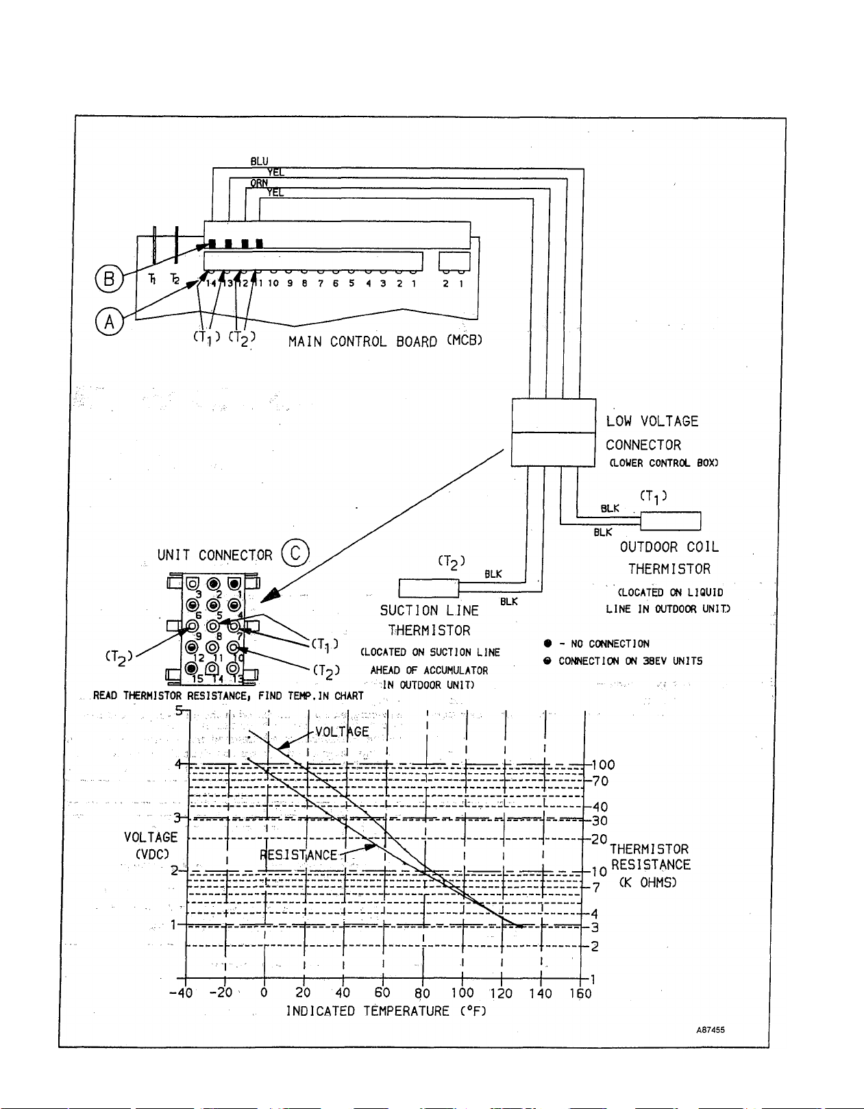
ERROR CODE #3 - OUTDOOR THERMISTOR FAILURE
ERROR CODE #4 - SUCTION THERMISTOR FAILURE
REASON: CONTROL BOARD READS THERMISTOR TEMPERATURE ABOVE 160T OR BELOW -40T.
POSSIBLE CAUSES:
1) Thermistor failed or out of calibration (see Note 1).
2) Loose or corroded connection.
3) Faulty control board.
Reference Figure 21
Notes:
1) If thermistor is out of caiibra:tion, it may read accurately when system Is off, but may drift from actual
temperatures during operation.
2) COOL MODE: Monitor temperature at unit service valves.
HEAT MODE: Monitor temperature inside unit at thermistor location.
3) Adjust thermostat 4°F or more above or beiow room temperature, depending on mode, to force system
to high speed.
4) if unit has been off a short time, allow refrig, temperatures to stabilize.
A87475
Page 18

Page 19

ERROR CODE #5 - INDOOR THERMISTOR FAILURE
REASON: CONTROL BOARD READS TEMPERATURE ABOVE ISCTF OR BELOW -SCTF.
POSSIBLE CAUSES: 1) Thermistor failed or out of calibration (see Note 1).
2) Loose or corroded connection.
3) Faulty control board, Interface board or cable.
Reference Figure 22
Notes:
1) If thermistor Is out of calibration, it may read accurateiy with system off, but may drift from actual
temperatures during operation.
2) For furnace appiications - Remove furnace access panei and tape kili switch so that panel can later be
removed for blower inspection without breaking power.
Reinstall access panel.
3) Adjust thermostat 4°F or more above or below room temperature, depending on mode, to force system
to fuli speed.
A87477
Page 20

fi
J
20
Page 21

ERROR CODE #8 - LOCKED COMPRESSOR ROTOR Reference Figure 23
REASON; OVERCURRENT OR UNDERCURRENT SITUATION OCCURS DURING FIRST 2 MINUTES OF COMPRESSOR
OPERATION.
POSSIBLE CAUSES; 1. Loose high voltage lead
2. -036 Models; scroll compressor running backwards
3. Failed compressor
4. Failed inverter
I 1
V.
Notes;
1) Inverter alarm may be monitored using DC voltmeter at@, in Figure. Alarm-on is 1VDC. Alarm may energize before
inverter trips.
Inverter trip LED (yellow) may be viewed by removing safety sheild from upper control box. View downward into box,
beyond contactor and under main control board at inverter board. See Figure 7 for LED location.
Power (red) LED should light whenever contactor closes.
Power and Trip LED’s will go off when contactor de-energizes.
2) When contactor energizes, inverter output voltage will increase gradually for about 30 seconds before leveling off.
Inverter may trip on low current at about 10 seconds. as7478
Page 22

YEL
HIGH VOLTAGE
CONNECTOR
(LOWER CJONTROL BOX:
Fig, 24—Error Code 9
Q
A87458
Page 23

n
ERROR CODE #9 - OVERCURRENT TRIP
REASON; OVERCURRENT SITUATION AFTER FIRST 2 MINUTES OF RUN TIME.
POSSIBLE CAUSES: 1) Defective compressor or inverter.
2) Failed control board.
3) loose or corroded high voltage or inverter alarm connection.
4) Excessive loading due to:
Cool Mode - improper fan operation, dirty outdoor coil, overcharge.
Heat Mode - improper blower operation, dirty air fiiter, blocked duct, overcharge.
Reference Figure 24
Notes:
Inverter alarm may be monitored using DC voltmeter at(A)(see Fig). Aiarm-on is 1 VDC. Alarm may ener
1)
gize before inverter trips.
Inverter trip LED (yellow) may be monitored by removing safety sheild from upper control box. View
downward into box, beyond contactor and under main control board at inverter board. See Figure 7 for
LED iocation.
Power (red) LED should light whenever contactor closes.
Power, Trip LED’s will go off when contactor de-energizes.
Adjust thermostat 4°F or more above or beiow room temperature, depending on mode, to force system to
2)
fuil speed. kmm
Page 24

• - NO CONNECTION
« - CONNECTION ON 38QV ONLY
(WIRE NUT CONNECTIONS - 036 ONLY -
INSIDE COMPRESSOR CONTROL BOX)
SUCTION LINE)
3BQV - (LOCATED ON
SERVICE VALVE
LIQUID LINE)
Fig. 25—Error Code 10
LIQUID LINE)
38QV - (LOCATED ON
COMPRESSOR
DISCHAROE LINE)
A87473
Page 25

ERROR CODE #10 - CONTACTOR CONTROL FAILURE
REASON: THERMISTOR TEMPERATURES DID NOT CHANGE AFTER 5 MINUTES OF RUN TIME,
(i.e. REFRIGERANT NOT CIRCULATING IN SYSTEM) see Note 4.
POSSIBLE CAUSES: 1) Failed contactor, or control board output.
2) High, low pressure, or ESS (-036 only) switch.
3) Very low charge.
4) Stuck reversing valve.
Reference Figure 25
U
1) inverter POWER (red) LED can be viewed from above the control box. CAREFULLY remove white safety shield.
Look downward into box beyond contactor and behind main controi board at inverter board. See Figure 7
for LED location. Red LED shouid be on whenever contactor is energized, and outdoor unit power is on.
2) ESS - to - LPS spiice is iocated in compressor terminai box.
3) -036 Modeis Oniy
If compressor has been serviced or repiaced, check for proper 3-phase wiring connections.
If leads are miswired, compressor will not pump in reverse direction.
4) Error code may not appear untii up to 5 minutes after startup (outdoor fan energizes).
A87474
Page 26

1
REV n/10/87
® - NO -CONNECTION ..
e - CONNECTION ON 38QV ONLY
UNIT CONNECTOR
Fig. 26—Error Code 11
OR
REVERSING VALVE
SOLENOID CRVS)
(LOCATED ON 4-WAY
VALVE) C38QV UNITS)
A87459
Page 27

ERROR CODE #11 - REVERSING VALVE FAILURE (38QV HEAT PUMPS ONLY)
REASON: INDOOR THERMISTOR DOES NOT DROP IN TEMPERATURE AFTER SYSTEM STARTUP (COOL
MODE ONLY) see Note 1.
POSSIBLE CAUSES: 1) Reversing valve stuck.
2) Reversing valve coil not energizing.
3) Indoor thermistor not installed property.
:f I
Notes:
1) Error code may not appear until up to 5 minutes after startup.
A87466
Page 28

ERROR CODE # 14 - INDOOR COIL FREEZE
REASON: SUCTION THERMISTOR READS BELOW 32° F.
POSSIBLE CAUSES; 1) Blocked return or supply duct.
2) Dirty air filter.
3) Suction thermistor out of calibration (see Note 1).
Notes: kzim
1) If thermistor is out of calibration it may read accurately with system off, but may drift from actual during operation.
Page 29

ERROR CODE #15 - LOW REFRIGERANT CHARGE (see Note 1).
REASON: LARGE REFRIGERANT TEMPERATURE RISE THROUGH INDOOR COIL (COOL MODE),OR OUTDOOR COIL
(HEAT MODE).
POSSIBLE CAUSES: 1) Low refrigerant charge.
2) Plugged or failed solenoid expansion valve (SEV).
Notes:
1) Error code will not affect system operation, and will only be displayed at control board LED.
2) Superheat Tables provided in outdoor unit installation instructions.
3) In outdoor ambients below 75-80°F in Cool, above 45°F in Heat, system will not go to full speed, and SEV should be
cycling on-off.
4) Refer to Figures 15 and 16 to see location of valve orifices. Valve main orifice may be cleaned by blowing air, etc. into
outlet of valve. If this is unsuccessful, replace valve.
------------
A87471
Page 30

PUSH A SHARP OBJECT
INTO WIRE TERMINAL
HERE TO UNLOCK AND
■ f
REV 11/10/87
CLOCATED ON SERVICE
VALVE LIQUID LINE)
C38QV UNITS ONLY)
»
A87460
Fig. 27—Outdoor Unit Soienoid Expansion Vaive (SEV)
Page 31

(if
(ERROR CODE #15 CONTINUED)
38QV UNITS ONLY
Reference Figure 27
Note:
5) Superheat should be less than 5°F, but may be up to 10°F in above 40°F outdoor temperatures.
A87470
Page 32

22-30 VAC CIRCUIT
(TERMINALS #1,2)
1 \2 3 4 5 S 7 8
rrniITT
CONTROL BOARD
PLUG
(A)
OUTDOOR UNIT
MAIN
CONTROL BOARD
8 7 8 5 4 3 2 1
1 111 ITr T
)
22-30 VAC
(TERMINALS #1,2)
©
ut
___________
NTERFACE BOARD
RECEPTACLE
1
)
■ 208/230 VAC
....
INPUT
TRANSFORMER
Q)
A87461
Fig. 28—Control Board LED Does Not Light
Page 33

Notes:
1) For 208VAC applications •* Check (2) transformers at indoor unit to make sure red (230VAC) transformer lead connections
are replaced by blue (208VAC) transformer leads.
2) For furnace applications - Remove furnace access panel and temporarily tape kill switch so control power can be sup
plied to outdoor unit. A87467
Page 34

SPEED ON-OFF
O DODO O'O 0,
p 2 3 4 5 6 7 a/
\o O O O O o o_7
V 9 10 11 12 13 14 Iff
CABLE CONNECTOR
ON-OFF SPEED
1-14 VDC .1-14 VDC
TTiiYiii-
■
/ )L Jl /
INTERFACE BOARD
INTERFACE
BOARD
INTERFACE BOARD
TEST POINTS
SPEED
1-14 VDC
ON-OFF
-.1-14 VDC
INTERFACE BOARD
CONNECTOR
iCj
BLOWER
SPEED ON-OFF
r
CONTROL BOARD
CONTROLLER
OUTDOOR UNIT
MAIN
CONTROL BOARD
PINS
MOTOR
RESISTANCE
©
COHMS)
1-2
1-3 OPEN
1-4 OPEN
2-3
2-4
CONTROL BOARD
J
TEST POINTS
3-4
5-6
OPEN
9-14
9-14
9-14
0
j
H? (d
-,5 -2
5 3
MOTOR
CONNECTOR
1 1
Fig. 29—Indoor Blower Failure
A87462
Page 35

INDOOR BLOWER FAILURE
f V Reference Figure 29
Notes;
On some models, removal of blower housing is required to determine if wheel is rubbing.
1)
Refer to indoor unit installation instructions for service and repiacement procedures:
2)
For fan coiis without eiectric heat, piace (2) jumpers at Interface board from L1 to C, and L2 to 1 (or 2).
3)
If Neither Speed or On-Off signals are present, wait longer and recheck, as it could take 2-3 minutes for blower to start in
4)
some cases, ■
if biower starts, break power, remove jumper and place between R and W2(or W). Reset power and check to see that
5)
electric or gas heat operate. If not, refer to “Electric/Gas Heat Failure.”
Voltage at C and 1 (or2) may also be read by removing interface box cover and reading at solder joint connections on
6)
board. A87469
Page 36

CONTROL BOARD
S.TS15 R.DUELL 11/10/07
Fig. 30—Electric/Gas Heat Failure
A87463
Page 37

ELECTRIC / GAS HEAT FAILURE
Reference Figure 30
Notes:
1) For furnace applications - Tape the kill switch under access cover so unit can be started and inspected during opera
tion.
2) For furnace applications - Blower will go to high speed 2-3 minutes after burner ignites.
Page 38

/-• V:
u
Fig. 31—Outdoor Fan Circuit
Page 39

©
MISCELLANEOUS MALFUNCTIONS
1) LED stays on after power up.
Reason; Malfunction of communications between thermostat and outdoor unit main control board.
Check For:
A. Improper wiring of thermostat.
B. Loose/corroded connection at:
• thermostat
• indoor unit interface board
• Interface cable at indoor or outdoor unit
C. Defective controi board or thermostat (see Thermostat Section).
2) Compressor does not operate.
• See Error Code #10.
3) Outdoor fan does not operate.
• Fan motor is standard single phase component. Check for failed motor, capacitor, or control board using
Figure 31.
4) Compressor and outdoor fan do not operate.
• Initiate “Run Test” jumper. If either component operates, follow checkout procedure for the failed component
in this section. If neither operates replace control board. If both operate, and control'board LED goes off, unit
is not receiving capacity demand from thermostat. Make sure proper Heat or Cool switch is in “Auto” at
thermostat, and setpoint is at least 2°F away from setpoint. Pull “Speed-Up” jumper to bypass 5 minute
timeguard. If unit does not start within 5 minutes, Follow same procedure for #1 above, “LED stays on after
power up.”
5) Compressor cycles on-off, outdoor fan stays on.
• Compressor is cycling on safety device. See Error code #10 and Figure #25 to investigate excessively high
or low pressures. Check for proper charge, failed fan, blower or failed/plugged solenoid expansion valve.
6) Thermostat display malfunction.
• See thermostat troubleshooting section and instructions included with thermostat.
7) Rev/efsirig válvé does hot operate.
• See Error Code #11.
8) Indoor coil freezing.
• See Error Code # 14.
9) System running abnormally low suction pressures.
• See Error Code #15.
'4. ^
A87465
Page 40

STEP 6—Service And Maintenance
TABLE OF CONTENTS
38EV, 38QV Outdoor Unit Service and Maintenance Page
—Replacement of:
Service Valves......................................................................40
Refrigeration Cod
Control Box..........................................................................40
Outdoor Pan........................................................................41
Compressor
Reversing Valve
Main Control Board...........................................................41
Thermistors............ ...........................................................41
Contactor.............................................................................42
Emergency Stop Switch (ESS)...........................................42
Solenoid Expansion Valve (SEV)
Outdoor Unit
Indoor Unit
Interface Cable....................................................................42
Low, High Pressure Switches
Crankcase Heater, Switch and Fan Motor
Electrical Terminals, Connectors......................................43
—Elimination of Television, Radio Interference
—Maintenance:
Fan Motor Lubrication 43
Compressor Oil. .. ...........
Coil and Heat Sink Cleaning............................................. 43
40 QV Fan Cod, 58SSB blower Accessory Service
and Maintenance.....................................................................44
38EV, 38QV Outdoor Unit Service and Maintenance
NOTE: Malfunction of certain electronic control compo
nents can cause lack of Automatic Emergency Heat initia
tion. See below for corrective servicing procedures.
Component replacement and maintenance procedures are
covered in this text. Refer to 38EV or 38QV Instadation
Instruction for the foUowing procedures:
—System Startup Checkout
—System Charging
—Optimizer, Electric Heat Lockout Setup
—Blower Speed Checkout, Adjustment
Manual Emergency Heat Activation—
38EV and 38QV systems are designed to automaticaUy pro
vide emergency gas or electric heat in the event of compres
sor lockout on a system malfunction.
However, certain system control malfunctions may cause
lack of emergency heat initiation.
In the event that replacement parts are not readdy avadable
in the heating season, malfunction of the main control board
or interface cable can be manuaUy bypassed as described
below to restore gas or electric heat operation.
Note, however, that a malfunction of the interface board
causing inability to control blower speed, or fadure of
blower motor or controUer cannot be bypassed and must be
repaired.
Install a standard thermostat in the heated space for tempo
rary control untd the system can be repaired. Connect ther
mostat leads to the indoor unit terminal board across R and
W, as connected in conventional systems. The interface
board wdl control gas or electric heat to setpoint of the tem
porary thermostat.
COMPONENT REPLACEMENT
Before replacing any component in the entire system, turn
off main power to system. There may be more than one dis
connect switch. Turn off accessory heater power, if
...............................................................
.........................................................................
..................................................................
......................................
...................................................................
......................................................................
............................................
......................
.............
...........................................................................
40
41
41
42
42
42
43
43
applicable.
A WARNING
High voltage circuit remains energized after main dis
connect is opened. Normal capacitive discharge time is
ten (10) minutes, but this period may be extended indef
initely by component fadure. Before servicing, always
check with D.C. Voltmeter between contactor terminal
#23 (violet wire) and ground. Do not service until read
ing is lOVDC or less. Electrical shock can cause per
sonal injury or death. Always re-install safety shield in
top of control box after servicing.
A CAUTION
Aluminum tubing is used in unit cods. Do not overheat
or place excessive strain on tubing or damage may
result.
NOTE: To remove reversing valve, accumulator or compres
sor, control box and coil must be removed first. Coil
removes quickly and easdy. The minimal time required for
cod removal facilitates service and component removal. See
instructions below.
SERVICE VALVE REMOVAL-Cod must be removed to
remove screws holding service valves.
COIL REMOVAL
1. Shut off power to indoor and outdoor units.
2. Remove refrigerant from unit, using refrigerant
removal methods described in Carrier Standard Service
Techniques Manual, Chapter 1, Refrigerants. Be sure
system is 0 psig before proceeding.
3. FoUow steps 4 through 12 below.
CONTROL BOX REMOVAL
Make sure power is off to indoor and outdoor units.
4. Remove control box cover (3 screws).
5. Disconnect (3) in-hne electrical connectors in lower con
trol box.
6. Disconnect power leads and interface cable if control
box cannot be removed and set aside with them
attached.
7. Remove (8) screws securing control box to louvered cas
ing and (2) securing support legs to base pan.
43
A WARNING
High voltage circuit remains energized after main dis
connect is opened. Normal capacitive discharge time is
ten (10) minutes, but this period may be extended indef
initely by component failure. Before servicing, always
check with D.C. Voltmeter between contactor terminal
#23 (violet wire) and ground. Do not service until read
ing is lOVDC or less. Always re-instaU safety shield in
top of control box after servicing.
8. Supporting control box with one hand, remove safety
shield and (2) top screws securing box to fan orifice
ring. Remove control box by sliding horizontally away
from unit.
NOTE: Before reinstalling box, gray plastic through-thecoU vent tube must be removed from control box. Do this by
squeezing top and bottom of vent where it protrudes from
rear of box. Then slide vent out through front of box, taking
care not to damage wires.
Once the box is fuUy reinstalled, slide vent into slot in rear
of box and through existing opening in coil. Make sure front
lip of vent is against rear panel of box.
/tn
Page 41

OUTDOOR FAN/MOTOR REMOVAL—
Make sure power is off to indoor and outdoor units.
9. Remove fan/motor/orifice assembly by removing
remaining 4 screws around orifice assembly. (If control
box is not being removed, remove safety shield, and (2)
screws in upper control box). See Warning, above.
Unplug motor wires from base of motor prior to lifting out
assembly.
Remove Coil—
Cutting tubing is recommended to avoid possibility of
fire, and personal injury.
10
Use midget tubing cutter to cut liquid and vapor lines
at either side of coil. Cut in convenient location for easy
reassembly with copper slip couplings.
11.
Remove 4 screws around base pan securing louvered
casing and wire coil wrap. Set louvered casing aside.
12. Lift coil vertically off base pan and place carefully to
one side.
NOTE: While coil is removed from unit for intended service,
use this opportunity to remove and replace strainer.
COMPRESSOR REPLACEMENT
Check whether
tiedown bolts/
1. Remove control box, fan and coil as described under
Cl
“CoU Removal” above.
2. Disconnect electrical leads from compressor.
Compressor is Srphase—Note lead locations for proper
wiring of replacement compressor.
-024 Models: T1 — Black
-036 Models: U — Black
3. Cut compressor suction and discharge tubes at conven
ient location.
4. Loosen and remove crankcase heater (-036 models
only).,/ /
5. Remove compressor mounting bolts.
6. Lift compressor out.
7. Carefully unbraze suction and discharge fine piping
stubs frora compressor. Note position of stubs to assist
when reinstalling.
8. Install new compressor. Install crankcase heater
around compressor (-036 models only). Install compres
sor mounting bolis.
9. Braze suction and discharge fines to compressor (where
unbrazed in Step 7) and piping stubs (at point where
cut in Step 3 above). Rewire compressor.
10. Replace coil,;braze liquid and vapor line. Test for leaks.
11. Replace fan/motor/orifice assembly.
12. Replace control box and reconnect wiring., (See note
above, under “Control Box Removal.”)
13. Evacuate and recharge system
À WARNING
A CAUTION
unit is fastened to platform with
Wire
Marking Color
.....
:T2~WeUbw
T3 — Blue
V —Yellow
W -Blue
......
INSTALL FILTER DRIER-Install field-supplied heat
pump filter drier in system liquid fine when refrigerant sys
tem is opened for service as described under “Compressor
Replacement,” above. Position drier in liquid fine at conven
ient location.
REVERSING VALVE REPLACEMENT (38QV Only)
1. Remove coil as described in “Coil Removal,” above.
2. Cut 4 legs of valve using midget tubing cutter.
3. Wrap replacement valve with wet cloth to prevent
overheating.
4. Replace new valve using tubing slip couplings.
MAIN CONTROL BOARD REPLACEMENT
a) Unplug Interface Cable from bottom L.H. side of board
by sfiding small metal retainer right.
b) Unplug white 17 pin connector and two fan motor
push-on leads (Black) from top of board. Use caution to
prevent board damage when removing connections.
c) Using fingers or small tipped pliers, depress plastic
tabs on board standoffs (4) on corners of board and (1)
near center (below black heat sink on board). Lift board
out of position.
d) Align new board on plastic standoffs, and push board
down over standoffs until small locking tabs secure
board in place.
e) Reinstall 2 (black) fan wires and white connector at top
of board. Be sure white connector is aligned correctly.
Reinstall interface cable, sfiding metal locking retainer
to the left.
f) Cut only those program jumpers on new board (ref.
Fig. 5) which were cut on old board.
A CAUTION
Failure to cut the proper programming jumpers wffl
result in improper operation. Jumpers not cut on the
old board must remain uncut. Inadequate operation and
equipment damage may result.
Jumper functions are fisted, in. Table , 3 for reference
.
purposes.
g) Set Optimizer Pot (ref. Fig. 5) on 38QV Heat Pump
units if jumper, jJ4 or J5 is cut. Adjust to same setting
as old board, or refer to procedure for optimizer or elec
tric heat lockout setup in 38QV unit Installation
Instructions.
Table 5—Programming Jumpers
Jumper
No.
J1
J2,J3
J4
J5
J6, J7
*38QV Systems only
THERMISTOR REPLACEMENT
a) Break power to indoor and outdoor units.
b) For outdoor unit thermistor replacement, remove top
grille.
c) Cut plastic ties holding foam tube over thermistor.
Thermistor is mounted inside %e" copper tube soldered
to refrigerant fines and is retained by one (1) plastic tie.
Remove this tie and remove thermistor.
38QV Heat Pump
Systems
UNCUT CUT
UNCUT
CUT FOR 58SSB FURNACE APPLICATIONS
' CUT FOR ELECTRIC.
HEAT LOCKOUT AT HIGH
OUTDOOR TEMPERATURES*
UNCUT UNCUT
38EV Cooling
Systems
UNCUT
UNCUT
Page 42

d) Cut thermistor leads about 12" back from end. Cut
replacement thermistor leads to about 16" long, strip
back all leads, and splice leads together with a crimptype connector. Use silicone sealer in connector to
make it waterproof.
e) Re-insert thermistor into %e" tube, retain with (1) plas
tic tie around wires and refrigerant tube. Be sure
thermistor is not sticking out end of tube. Fill both
ends of small tube with petroleum jelly and similar.
f) Wrap thermistor tube with same 3" piece of armaflex
insulation, or similar. SUt of foam insulation must be
on opposite side of refrigerant tube from thermistor
;weU. -Tie in-place-with (2) plastic-ties-as-before.
CONTACTOR REPLACEMENT
Break power to indoor and outdoor units, and remove con
trol box cover.
a) Disconnect aU wires to contactor noting attach point to
component. Refer to unit wiring diagram. Loosen upper
left mounting screw and remove lower right screw.
Remove contactor and replace.
b) Rewire contactor following unit wiring diagram.
A CAUTION
Make sure contactor wiring is correct before starting
unit. Left side of contactor (terminals #11 and #21) of
contactor is for 230 VAC input power. Right side (ter
minals #13 and #23) is 300 VDC supply to inverter
board (violet wires).
EMERGENCY STOP SWITCH (ESS) REPLACEMENT
(38EV036 and 38QV036 Only)
a) Break power to indoor and outdoor units.
b) ESS .switch is in series with low pressure switch arid is
connected with wire nuts within the compressor junc
tion box. Remove unit top grille and compressor sound
shield. Switch is located on top of compressor under a
special rnetal clip with white wires going to junction
box.
b) Push switch (rectangular aluminum body) toward wire
end and it will slip out from under clip.
c) DO NOT remove wires from compressor junction box.
Cut white wires about 6" out of box.
d) Slidé new switch under clip until it hits stop at end of
i . cHp. ''i":';-V ■
e) Re-wire switch to old white wires out of compressor
junction box with wire nuts. Note wires are #20 gage so
use appropriate nuts. Fill connector cavity with sili
cone sealer.
f) Replace sound shield and top grille.
EXPANSION VALVE COIL REPLACEMENT
a) Break power to indoor and outdoor units. For outdoor
SEV replacement, remove top grille.
b) Reiriove nut holding solénoid on body of valve. Cut
wires about 12" away from coil.
c) Replace with new solenoid. Cut leads of new coil to
about 16" long. Splice with crimp-type connectors.
Reinstall nut and harness wires as before. Use silicone
sealer in connector cavity.
d) Replace top grille (for outdoor SEV replacement).
ELECTRONIC.EXPANSION VALVE REPLACEMENT
38QV OUTDOOR UNIT-
See Figs. 2 and 3 for Locations of Outdoor Unit SEV.
a) Break power to indoor and outdoor units.
b) Remove top grille.
c) Remove system charge using proper procedures.
-----—
d) Remove solenoid coil. Using two (2) wrenches, loosen
the flare nuts holding valve to tube. USE CARE to not
twist tubing. Remove valve. Remove piston as you
would in a standard unit when piston is in service
valve.
e) Insert same piston or new piston and new retainer in
new valve. Set valve in liquid line and hand-tighten
flare nuts. Tighten nuts to 10-15 lb. ft. Note: Use care
to not overtighten valve connections, which could
deform valve and bind pistons. This valve must be
mounted with coil in a vertical position as on original
installation. Piston must be at valve end toward serv
ice valve, with arrow on valve body toward coil. Rein
stall solenoid coil, and top grille.
f) Recharge system.
Indoor Location—
The indoor SEV valve is located on the liquid line at the
indoor coil.
38QV Heat Pump Systems—foUow procedure for outdoor
unit SEV replacement, above. When installed, new valve
should have arrow on body toward indoor unit, accurator
piston end facing toward outdoor unit.
38EV Cooling Systems—
a) Break power to indoor and outdoor units.
b) Remove system charge using proper procedures.
c) Remove thermistor insulation by cutting tie wraps.
Cut tie wrap securing thermistor leads to line, and slide
thermistor out of well.
d) Remove solenoid coil. Using two (2) wrenches loosen
flare nuts holding valve assembly in place. Use care not
to twist indoor unit fitting. Remove valve assembly.
e) Carefully unbraze valve from assembly tubes and braze
in new valve.
f) Set valve in Hne and hand-tighten flare nuts. Tighten
nuts to 25-30 Ib-ft.
g) Reinstall thermistor, insulation, and solenoid coil.
h) Recharge system.
INTERFACE CABLE-
a) Break-power to outdoor and indoor units.
b) Disconnect interface cable from outdoor unit control
board by sliding locking latch to right. Disconnect
ground wire. Loosen black plastic nut on cable strain
relief and remove cable from slot in box. The new cable
will have a new strain relief attached.
c) Disconnect interface cable from indoor interface con
trol box by squeezing the metal tabs on the cable end.
Unfasten cable black ground wire with ring terminal
from sheet metal screw. Route cable out through hole
provided in cabinet.
d) Remove ALL ties securing cable to refrigerant lines
and remove cable from instaflation.
e) Connect new interface cable to outdoor unit control
board. This cable is polarized so it will only go on one
way. Slide metal retainer left to retain cable. Reattach
black ground wire to sheet metal screw. Loosen black
plastic strain relief nut on cable, set in slot on box and
tighten nut. Use care to not put excess strain on con
trol board.
f) Working from outdoor to indoor unit, secure cable to
refrigerant lines every 2-3 ft. using tie wraps, or
similar.
g) Connect cable to indoor interface control board. Route
cable through holes provided in unit as before. This
cable end is also polarized so it will only go on one way.
Page 43

Squeeze clips on cable and insert in receptacle on box.
Reattach black ground wire to sheet metal screw,
LOW AND HIGH PRESSURE SWITCH, REVERSING
VALVE SOLENOID
: ' These components are the same as on any Carrier unit, and
can be replaced using normal procedures with the following
exception:
The wiring back to the control box is through a 15 pin
plug connection, so the wires must be cut within 12 to 15
inches of component and replaced with new part using
wire splice with crimp-type connection. Use sihcone sealer
in connector cavity.
CRANKCASE HEATER SWITCH, CRANKCASE HEATER,
FAN MOTOR
Crankcase Heater Switch: One lead goes to junction box on
compressor, attached with wire splice. Replace as required.
a) The second wire is connected to the control box
through a six pin plug connection. Note location of
CHS on liquid tube. Remove switch with pliers squeez
ing clip as on a standard unit. Cut wire about 12 to 15
inches away.
b) Install new switch. Cut leads to 15 inches and splice to
unit leads. Use splice with crimp-type connection. Fill
splice cavity with silicone sealer to make splices
waterproof.
Crankcase Heater: These components are the same as on a
standard unit. Replace as required. Cut leads back 12" from
component and splice in new heater leads. Seal splice con
nections with sihcone.
Electrical Terminals (Within Unit Plugs)
I To repair terminals within the three (3) unit plugs in the out
door section and plug on interface box in indoor section a
terminal kit is available from Service Parts.,#38QV660001.
This kit contains 12 each of every plug and receptable termi
nal used within system. Also included is a removal tool for
terminals inside receptacles.
Possible Television, Radio and Home Computer Screen
Interference
NOTE: This equipment generates and uses radio frequency
energy. If not installed properly, it may cause interference
with TV and/or radio reception. This system has been
designed to provide reasonable protection against such
interference in a residential installation. If this system does
cause such interference to TV and/or radio reception, which
can be checked by turning the system on and off, check the
following;
Check Interface Cable—
a) This cable has a black ground lead that is attached to
the sheet metal on both the outdoor unit and indoor
unit. Check that the lead is properly installed and not
insulated by a painted surface.
b) If installation uses two (2) interface cables connected
together, the middle connection has two black ground
wires that must be connected together with the pro
vided bolt, nut, and lockwasher. If not, use a #10 x %"
bolt and locknut.
c) Check that black ground lead is connected to black
plastic plug case. Plastic case can be opened to check
that' wireis connected to cable shielding. If not, replace
cable or fix loose wire with soldering gun. Use care not
to burn wires.
d) Check that cable is installed properly. This cable must
be installed alongside refrigerant tubing and tied to it
as much as possible.
Check Unit Ground Connection—
a) Outdoor Unit: Inside control box cover is an aluminum
lug attached to box. Field ground connection must be
connected.
b) Indoor Unit; (Fan-Coil or furnace) check for similar con
nection inside control box.
Check Indoor Unit Thermostat Wires—
a) System thermostat leads run from interface control
box board (TB-4) on fan coil or furnace kit (see unit wir
ing label) to Parker thermostat. Leads must be
shielded.
b) Thermostat leads leaving interface box must run
through an EMI shield (ferrite-“iron” core—%" O.D. x
%” I.D. X 2%" long.
c) If core is not installed, order from Service Parts
#HK99FA001.
Check Location of Television, Radio or
Monitor to System—
a) If cable shielding and EMI shield are not in place, this
system is designed to not interfere if appliances are 30
ft and one wall away from system (indoor or outdoor
units).
b) Move TV receiving antenna to eliminate interference.
c) Check that TV, radio or monitor are not on the same
electrical circuit as the system.
d) Ensure that cable grounding and EMI shield are
installed.
Check Other Computer or Signal Generating
Devices In House—
a) Appliances hke modern dishwashers, dryers, sewing
machines, power tools, room air conditioners can emit
the same signals.
b) Check that these appliances are not on the same electri
cal circuit as the system.
MAINTENANCE
A WARNING
Before performing recoromended maintenance, be sure
unit main power switch is turned off. Failure to do so
may result in electric shock, injury or death from rotat
ing fan blade.
Lubrication
FAN MOTOR BEARINGS—Oiling holes are provided at
each end of condenser fan motor. Remove fan motor and
lubricate motor with 32 drops (16 drops per hole) of SAE-10
riondetergent oil at intervals described below.
a) Annually wheii environment is very dirty, ambient
temperature is higher than 105 F (40 C), and .average
unit operating time exceeds 15 hours a day.
b) Every 3 years when environment is reasonably clean,
ambient teinperature is less than 105 F (40 G) ^d unit
operating time averages 8 to 15 hours a day.
c) Every 5 years when environment is clean, ambient tem
perature is less than 105 F (40 C) and unit operating
time averages less than 8 hours a day.
COMPRESSOR contains factory oil charge. If oil requires
replenishment, see Table 1 for oil recharge and Carrier
Standard Service Techniques Manual, Chapter 1, Refriger
ants, page 1-21, for instructions. Use proper oil as listed in
Table 1.
Coil and Heat Sink Cleaning to be done at the beginning of
each cooling season or more often if required. (Heat sink is
located between control box and unit.)
Page 44

A CAUTION
Fin damage can result in higher operating costs or com
pressor damage. Do not use flame, high-pressure water,
steam, volatile or corrosive cleaners on fins or tubing.
Follow these instructions carefully. Contact your dealer
if you encounter problems.
1. Shut off power to unit.
2. Clean coil and heat sink using vacuum cleaner and coil
crevice tool (see Fig. 32). Work crevice tool vertically
making sure tool only touches dirt on coil fins. To pre-
“vent fin-damage, do not “scrub” fins with tool or move
tool horizontally.
3. If oil deposits are present, spray coil and heat sink with
ordinary household detergent. Wait 10 minutes then
proceed to step 4.
4. Using garden hose, spray coil vertically downw;ard
with a constant stream of water at moderate pressure
(see Fig. 33). Keep nozzle at a 15 to 20 degree angle,
about 3-in. (76 mm) from coil face and 18-in. (457 mm)
from tube. Spray so debris is washed out of coil and
heat sink.
5. Restore power to unit.
40QV Fan Coil, 58SSB Blower Accessory Service and
Maintenance—
Refer to related installation instructions for component
replacement, service and maintenance procedures.
For blower speed inspection and adjustment procedures see
related instructions and 38EV or 38QV outdoor unit instal
lation instructions.
Fig. 32—Crevice Tool
A87037
Fig. 33—Positioning Hose to Spray Coil
A87050
Page 45

i :i
\
Page 46

';l!|
til
COffONENT A RRAN6EHENT
YEL
OFM
BW
EU
■T7 J-
“ — --
m —
r 5
O yg
' 'il
O-^ FILTER
1—fo • ew O
■ "ÍDLirc5uiP.«D.
3 INTERFACE CABLE
T-1
~ —
FIELD POWER WIRINB
--
— •
FIELD CONTROL WIRING LPS
HARKED COMPONENT TERMINAL
0
UN1ARKED C0»f>C»€Hr TERMINAL
splice COWECTION
-< SOCKET TERMINAL
PIN TERMINAL
<•
BP-1,2,4 CIRCUIT BOARD PLUOS
C
CONTACTOR PMWPOWER MODULE 'W'
CM CRAMCCASE HEATER
. CMS
CRAWXA5E HEATER SWITCHRS
C0H»R
INVERTER CC»ff>RES50R 5-B-1
CAP
CAPACITOR
C-B-1CIRCUIT BOARD #1 (HITACHI)
C-B-2
CIRCUIT BOARD *2 CCarrl«r)
cr CLRCKT TRANSFORMER
FC FW CAPACITCR
FR FAN REUY
1. TO BE WIRED IN MXfSMi/X WITH N.E.C. AMD LOCAL CCCCS.
2. COW’RESSOR AMD FAN HOTCR TTBWaY PROTECTED.
3. MUST USE PAI9ZR THERMOSTAT tfHHOSZAOOI.
A. USE SUPPLIED INTEPfACE C/flLE FOR COMCTlOe BETWEEN UNIT AND INDOOR SECTION.
5. USE CJypER «»eUCTORS ONLY i
_BU
“BU
ELU BLU 6U BU BU BU
T-2
LESEND
HPS
MOV
CFHOUTDOOR FAN MOTOR
ore OVER TEMPERATURE CONTROL
P-1,2,3 1NTERCOWCCTINOPLU9S
PMUPOWER HOOULE 'U'
PMV
RS
BLEED RESISTCR
SURGE RESISTOR
SUB - BOARD «1
........
S^2
.
SUB - BOARD 42
SH SHUNT RESISTOR
T-1,2,3T1CRMIST0RS
TB
TERMINAL BLOCK
CP, CMCAPACITOR, fCGATIVE/POSiTI
NOTES
NOTE: Emergency Stop Switch (ESS) used on 036 size only.
-BU
"BU
HI6M PRESSURE SWITCH
LON PRESSURE SNITCH
METAL OXIDE VARISTOR
POWER MODULE 'V”
{ HOOEL HO.
----------—
3eEV500D44 REV E
A87480
Í
Fig. 35—38EV Component Arrangement
Page 47

Fig. 36—38QV Schematic Diagram
Page 48

COMPONENT ARRANGEMENT
YEL
OFM
BRH
ELK
f
T-1
I RVS I ELK
,a.K
"ELK
- a-K
' hj:
BL)C
SEV ГаГ"
ESS
LESEND
— —
FIELD POWER WIRINB H»S
—
FIELD CONTROL WIRINB LPS
HARKED CDM>ONENT TERHINAL
0
IMURKED COtf>ONENr TERMINALCFH
SPLICE CCNCOTKIN СПС
-< SOCKET TERMINAL
PIN TERMINAL PMU
BP7b2»4ClRCUIT BOARO PLUBS PHY
■'■c
CCWTACTOft - PHW
CH
CRANKCASE №ATER RB
CHS
CRANKCASE HEATER SWITCHRS
CT
CURRENT TRANSFORMER
C0№R
INITERTER CC»f>R£5S0R S-&-1
CAP
CAPACITOR S>e-2
C-B-1
CIRCUIT BOARD #1 CHITACHI)SEV
O-B-2
CIRCUIT BOARD *2 (Corrltr)SH
esst
EMER8ENCY STOP SWITCH
rc
PAN CAPACITOR ТВ
FR
FAN REUY CP, CNCAPACITOR, NEBATIVE^DSITIVE
1. TO BE WIRED Ж ACCORDANCE WITH N.E.C. AND LOCM. COOES.
2. FAN HOTOR THERNAUY РЛОТЕСГЕО.
Э. HUST USE PARKER TICRNOSTAT «HK05ZA001.
Ч. use EUPFUiD IKTSTACZ CMLE P№ COHCCTlOe КПЕЕН IMIT «Ю INDOOR SECTION.
5. USE COPPER CONDUCTORS ONLY
NOTES
HIBH PRESSURE SWITCH
LOW PRESSURE SWITCH
HOYMETAL OXIDE VARISTOR
OUTDOOR FAN HOTOR
CNER TEMPERATURE CONTROL
P-1,2,3 INTERCCNNECTlNe PLUBS
POWER HOOULE 'U'
POWER HODUU 'V'
POWER HOOULE
BLEED RESief~
SURBE RESISTOR
RVS
REVERSIHB VALVE SOLENOID
SUB - BOARD «1
SUB - BOARD «2
EXPANSION VALVE SOLENOID
SHUNT RESISTOR
T-t,2^3 THERMISTORS
TERMINAL BLOCK
1 MODEL NO. 360V036320
1 38eVS002M REV E
A87481
NOTE: Emergency Stop Switch (ESS) used on 036 size only.
Fig. 37—38QV Component Arrangement
4Я
Page 49

!i ■
ii '
VVT SINGLE-ZONE WIRING DIAGRAM
WITH 40QV VARIABLE SPEED FAN-COIL
VVT SINGLE ZONE WIRING DIAGRAM
FOR ACCESSORY FURNACE VARIABLE SPEED KIT.
Page 50

Page 51

-V
Page 52

Manufacturer reserves the right to discontinue, or change at any time, specifications or designs without notice and without incurring obligations.
BookI 1 I 1 I 4 I 4 PC 101 Catalog No. 533-895 Printed in U.S.A. Form 38EV, QV-1SM Pg 52 12-87 ' Replaces: New
Tab I3al5al2al5a
i I
 Loading...