

Page 1
Number One
AirCoxIitbning
l\Mer
Installation, Start-Up '
Division of
Carrier Corporatio
e
Carrier Parkway • Syracuse NY 13221
and Service Instructions
Air-Cooled Condensing Units
INDEX
SAFETY CONSIDERATIONS......................
INSTALLATION
Step 1 — Check Equipment and
Jobsite..............................................................I
• UNPACK UNIT
• INSPECT EQUIPMENT
• COMPLETE OR CONSIDER
SYSTEM REQUIREMENTS
Step 2 — Make Piping Connections
• REPLACE THE ACCURATER™
REFRIGERANT CONTROL
PISTON IN THE INDOOR
COIL IF REQUIRED
• CONNECT REFRIGERANT LINES
Step 3 — Make Electrical
Connections....................................................5
• INSTALL A BRANCH CIRCUIT
DISCONNECT PER NEC
• ROUTE LINE POWER LEADS INTO
UNIT
• CONNECT GROUND LEAD AND
POWER WIRING
• CONNECT CONTROL POWER
WIRING
START-UP
SERVICE............................................................. 8-10
MAINTENANCE..................................................11,12
Installation and servicing of air conditioning
equipment can be hazardous due to system pressure
and electrical components. Only trained and quali
fied service personnel should install, repair or
service air conditioning equipment.
Untrained personnel can perform basic mainten
ance functions of cleaning coils and filters and re
placing filters. All other operations should be
performed by trained service personnel. When
working on air conditioning equipment, observe
precautions in the literature, tags and labels attached
to the unit and other safety precautions that may
apply.
Follow all safety codes. Wear safety glasses and
work gloves. Use quenching cloth for brazing opera
tions. Have fire extinguisher available for all brazing
operations.
...........................................
_______
...........................................................
SAFETY CONSIDERATIONS
Page
.. 1
. 1-6
2
6-8
WAR-NiNG: Before perfosrmisg service or
majnteiiatice орегайоиз or system, tarn off
vaaia power to isdoor tmit tsml outdoor
■ask. Тош off accessory beater power switch is
appiicaMe, E^ecfircal sihock, could cause pers<mal injury.
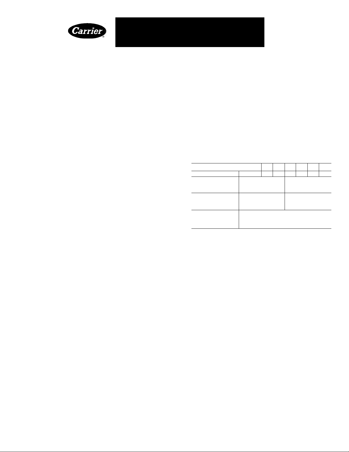
Table 1 — Physical Data (Refer to Fig. 1)
MODEL38EB
OPER WT(lb)
DIMENSIONS (ft-in.)
Diameter A
Height B
CONNECTIONS (in.)
Suction (ODF)
Liquid (ODF)
REFRIG LINES
Suction (in. ODF)
Liquid (in ODF)
*Fora1-1/8in suction line on 38EB048,060, a 3/4-in x 1-1/8 in suction
valve connection adapter is available as an accessory See Table 3
015 018
024
030
116
1-9-3/4
Recommended Field-Supplied Sizes
5/8 i 3/4 i 7/8 1 1-1/8
130
2-2-3/8 ) 2-8
5/8
137 165 181
INSTALLATION
Step 1 — Check Equipment and Jobsite
UNPACK UNIT — Move to final location. Slide
from carton taking special care not to damage serv
ice valves or grilles.
INSPECT EQUIPMENT — File claim with ship
ping company if damaged or incomplete.
COMPLETE OR CONSIDER SYSTEM RE
QUIREMENTS before installation:
Consult local building codes and National Elec
trical Code (NEC) for special installation
requirements.
When installing, allow sufficient space for airflow
clearance, wiring, refrigerant piping and service.
Maintain a minimum of 4 ft clearance from obstruc
tions above and 18 in. on sides of unit. Maintain a
distance of 24 in. between condensing units. Posi
tion so water from roof or eaves does not flow
directly on unit.
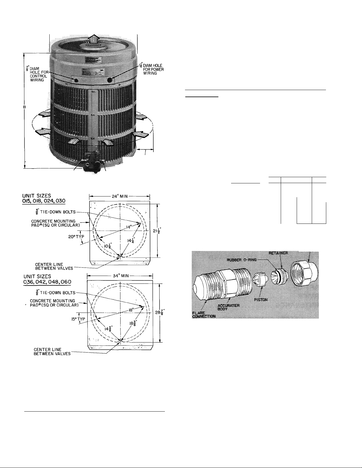
Install on a solid, level mounting pad. It is not
necessary to attach unit to pad but if desired or
required by local code, position tiedown bolts in
pad. Fasten unit to pad using 2 holes provided in unit
base. See Fig. 1.
036
2-2-3/8 1 2-8 1 3-2
3/
8
3/8
042
048 060
212 230.
2-5-1/4
3/4*
© Carrier Corporation 1982
Form 38EB-3SI
Page 2
4'-0" OVERHEAD SPACE REQUIRED
FOR SERVICE AND AIRFLOW
LIQUID VALVE SERVICE PORT
CONDENSER AIRFLOW
KW r-6''AIRFL0W
■•••••■ AND SERVICE
CLEARANCE
SUCTION VALVE SERVICE PORT
rectly sized for an evaporator of the same capacity as
the condensing unit, so piston change is not neces
sary. Mix-matching of condensing unit with evap
orator requires field replacement of piston. Refer to
Table 2. Replace piston, if required, before connec
ting refrigerant lines. Piston replacement instruc
tions are included in evaporator installation book.
After system installation is complete, use Charging
Chart to check and/or adjust refrigerant charge.
Condensing Units Connected to Carrier-Approved
Evaporators — Condensing units contain correct
system refrigerant charge for operation with evap
orator of the same size when connected by 25 ft or
less of field-supplied or Carrier accessory tubing.
Check refrigerant charge for maximum efficiency
(see Refrigerant Charging, page 6).
Table 2 — Optimization Chart
(Outdoor air design temperature, db-F,
100 F and below)
COND
UNIT
38EB
015 TWl 46 i
018 ’ . 4
024
030
036
042
048
060
Factory-installed piston. Obtain replacement pistons thru
local Carrier distributor.
ACCURATER™ PISTON NO.
Evap Size (Coil or Fan Coil)
ÒTFI”M4TCÌ301
> I j_V'
52
57
036
TXV
65
6? 70
048 060
042
— — —
— —
TXV
TXV
76
,...78...
_
62
—
p»
TXV
i 82
^CONCRETE PAD SHOULD WEIGH 1^ TO 2 TIMES WEIGHT OF UNIT
Certified dimension drawings available upon request
Fig. 1 — Dimensions, Connections and
Mounting Pad (Refer to Table 1)
Carrier Cooling System Capacity Optimization —
AccuRater™ (bypass type) refrigerant control, with
field-replaceable piston (see Fig. 2), is supplied on
evaporator. Use Optimization Chart, Table 2 to
find AccuRater piston size required for condenser/
evaporator system being installed. Pistons are cor-
njmm
Fig. 2 — AccuRater (Bypass Type)
Components
Step 2 — Make Piping Connections — Con
densing units may be connected to evaporator sec
tions using Carrier accessory tubing package (Table
3) or field-supplied tubing of refrigerant grade,
correct size and condition (Table 1). For tubing
requirements beyond 50 ft, obtain information from
local Carrier distributor.
If or
1$ osigd wism saaldog
If 1-1/8 in. tubing is used (38EB048,060), braze
it to the accessory 1 -1 / 8 x 3/4-in. suction connection
Page 3
adapter (Carrier Part No. 28VQ900011) or to cor
rectly sized field-supplied adapter, then make Com
patible Fitting connections.
WARNING: iX> NOT BURY UNESETS- If
fdfigerans
E b. veitkaS Ui« to the vah;« irastxsciioiis m
Isolate interconnecting tubing from framing and
ductwork or where tubing runs thru stud spaces, en
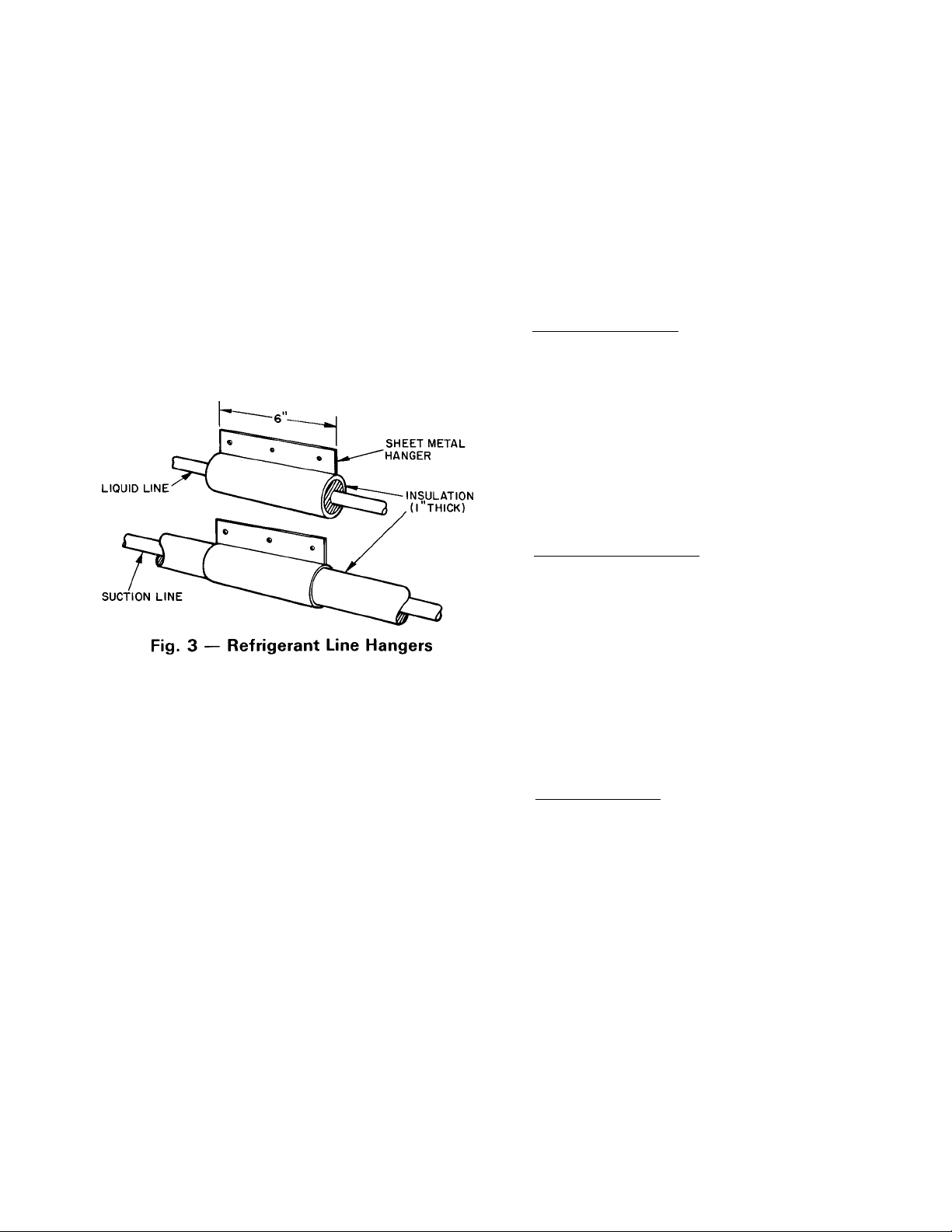
closed ceilings or pipe chases. Use isolation type
hanger (Fig. 3) since rigid fastening transmits pulsa
tions to structure creating objectionable sound.
For maximum capacity on 38EB048 and 060 sys^
terns use 1 -1 / 8 in. suction line. A capacity reduction
results if Carrier accessory tubing is used on these
systems. (Example; When a 25-ft accessory tubing
package is used on a 38EB048 system, the smaller
suction line results in a 3% capacity reduction.)
Length of interconnecting tubing may necessitate
refrigerant charge adjustment. Follow special re
quirements described in Start-Up, Refrigerant
Charging, page 6. Do not use less than 10 ft of inter
connecting tubing. On Carrier accessory tubing
packages, do not cut 5/ 16-in. or 1/4-in. liquid line or
7/8-in. suction line. These tubing packages have
swaged ends that, if cut, will not fit into refrigerant
line fittings. Bend or coil excess tubing to fit.
Do not use damaged, undersized or contaminated
tubing. Always evacuate or purge evaporator coil
and tubing system. When purging, use field-supplied
refrigerant, not unit holding charge refrigerant.
When making tubing connections, be sure to pro
vide clearance at unit for electrical connections.
REPLACE THE ACCURATER™ REFRIG
ERANT CONTROL PISTON IN THE INDOOR
COIL, if required, before connecting refrigerant
lines. See Carrier Cooling System Capacity Optimi
zation, page 2.
CONNECT REFRIGERANT LINES to fittings on
condensing unit suction and liquid service valves
(Fig. 1). Unit Compatible Fittings permit mechanical
(quick connect) or sweat connections.
Models 38EB048,060 — When using 1 -1 / 8 in. field-
supplied suction line, use field-supplied 3/4-in. by
1-1/8 in. suction valve connection adapter
(28VQ900011). Sweat connect refrigerant suction
line to 1-1/8 in. end of adapter. Be sure to provide
a heat sink at the service valve to prevent damage
during sweating operation. Connect 3/4-in. end of
adapter to unit suction line Compatible Fitting.
Connect liquid refrigerant line to unit. When a
7/8-in. field-supplied suction line is used, provide a
field-supplied 3/ 4-in. to 7/ 8-in. suction line adapter.
(Not necessary if 38LS accessory tubing is used.)
Mechanical Connection — (Mate one set of connec
tions at a time.)
1. Loosen nut on Compatible Fitting one turn. Do
not remove.
2. Remove plug and be sure O-ring is in the groove
inside the Compatible Fitting.
3. Cut tubing to correct length, deburr and size as
necessary.
4. Insert tube into Compatible Fitting until it
bottoms. Tighten nut until it bottoms on back
coupling flange. Keep tube bottomed in Compat
ible Fitting while tightening nut.
SweatT/onnection — (Use refrigerant grade tubing.-)
1. Remove locking nut, rubber O-ring and Schrader
core and cap from valve service port.
2. Cut tubing to correct length, deburr and size as
necessary.
3. Insert tube in Compatible Fitting until it bottoms.
Wrap top and bottom of service valves in wet
cloth to prevent damage by heat. Solder with lowtemperature (430 F) silver alloy solder.
4. Replace Schrader core and cap.
5. Evacuate or purge system using field-supplied
refrigerant.
Page 4

Table 3 — Accessories
PART NO.
38CQ900141
HH01AD040
HH93AZ040
HH07AT170
&
HH07AT174
HH93AZ176
HH01AD042
HH93AZ042
HH01YA192
HH93YZ194
38GS900102
38GS900212
HT32BH246
38UE900201
HC95DE088
HN61HB513
HC95DD121
HN61HB515
HC95DE066
HN61HB513
HC95DE088
HN61HB515
HC95DE088
HN61HB506
38EB660002
09WQ036,060
38GS900321
28VQ900011 Twelve 3/4- x 1-1/8 in Connection Adapters
PACKAGES
38LS958151 15
38LS958201 20
. 38LS958251 25 3/8
38LS958301
38LS958351
38LS958401
38LS958501
38LS934151 15
38LS934201
38LS934251
38LS934301
38LS934351
38LS934401
38LS934501
38LS978151
38LS978201
38LS978251 25
38LS978301 30
38LS978351
38LS978401 40
38LS978501
Solid-State Time Guard
(Six 38CQ900152)
Low-Voltage Control Honeywell Deluxe Thermostat
Thermostat Subbase
Low-Voltage Control
Honeywell Thermostat
Thermostat Subbase
Low-Voltage Control Honeywell Thermostat
Thermostat Subbase
Low-Voltage Control Grayson Thermostat
Thermostat Subbase
Indoor Fan Relay (Six HN61KJ210)
Low-Voltage Transformer (Six 38GS900091)
Crankcase Heater*
Crankcase Heater Relay (Six 38UE900212)*
Start Capacitor*
Relay*
Start Capacitor*
Relay*
Start Capacitor*
Relay*
Start Capacitor*
Relay*
Start Capacitor*
Relay*
Wire Bundle for Start Capacitors and Relays*
Refrigerant-to-Water Heat Exchanger for Chilled Water Systems
Liquid Line Filter Drier
Length
(ft)
30
35
40
50
20
25
30
35
40
50
15
20
35
50
OD
(in.)
3/8 3/8
3/8 3/8
5/16
5/16
5/16
1/4
3/8
3/8
3/8
3/8
3/8
3/8 3/8
3/8
3/8
3/8 3/8
3/8
3/8 3/8
3/8 3/8
3/8 3/8
3/8 3/8
DESCRIPTION
Liquid
Tube End
OD (in.)
3/8
3/8
3/8
3/8
3/8
3/8
3/8
3/8
3/8
3/8
3/8
3/8
3/8
TUBlNGt
Suctionj;
OD
(in.)
5/8
5/8
5/8
5/8
5/8
5/8
5/8
3/4 3/4 3/4
3/4
3/4 3/4 3/4
3/4
3/4
3/4 3/4
3/4
7/8
7/8
7/8
7/8
7/8
7/8
7/8
Tube End
OD (in.)
Evap
3/4**
3/4**
3/4**
3/4**
3/4**
3/4**
3/4**
3/4 3/4
3/4
3/4 3/4
3/4 3/4
3/4
3/4
3/4 3/4
3/4
3/4
3/4 3/4
3/4 3/4
Cond
MODEL
38EB
All
015300, 018300
024300, 030300
036310
042360
048310
All
048, 060
38EB
5/8
5/8
5/8
5/8
5/8
5/8
5/8
3/4 030, 036
3/4
3/4
3/4
3/4
3/4
015, 018, 024
r:'
*Available thru Carrier Service Parts
tFor maximum capacities, use suction line sizes recommended in
Table 1 Use of accessory tubing packages smaller than recom
mended may result in slight capacity loss (see Note 2)
tSuction line is insulated and has a 90 degree bend at one end
**For 5/8-in evaporator connection, cut off 3/4-in end
NOTES
1 Do not cut 3/8-in OD liquid line toa length shorterthan 10feet
Do not cut 5/16-or 1/4-in liquid line Do not cut 7/8-in OD
suction lines
2 Field-supplied 1-1/8 in suction line is recommended on
38EB048 and 060 If accessory tubing package is used, a
capacity reduction can result
Page 5
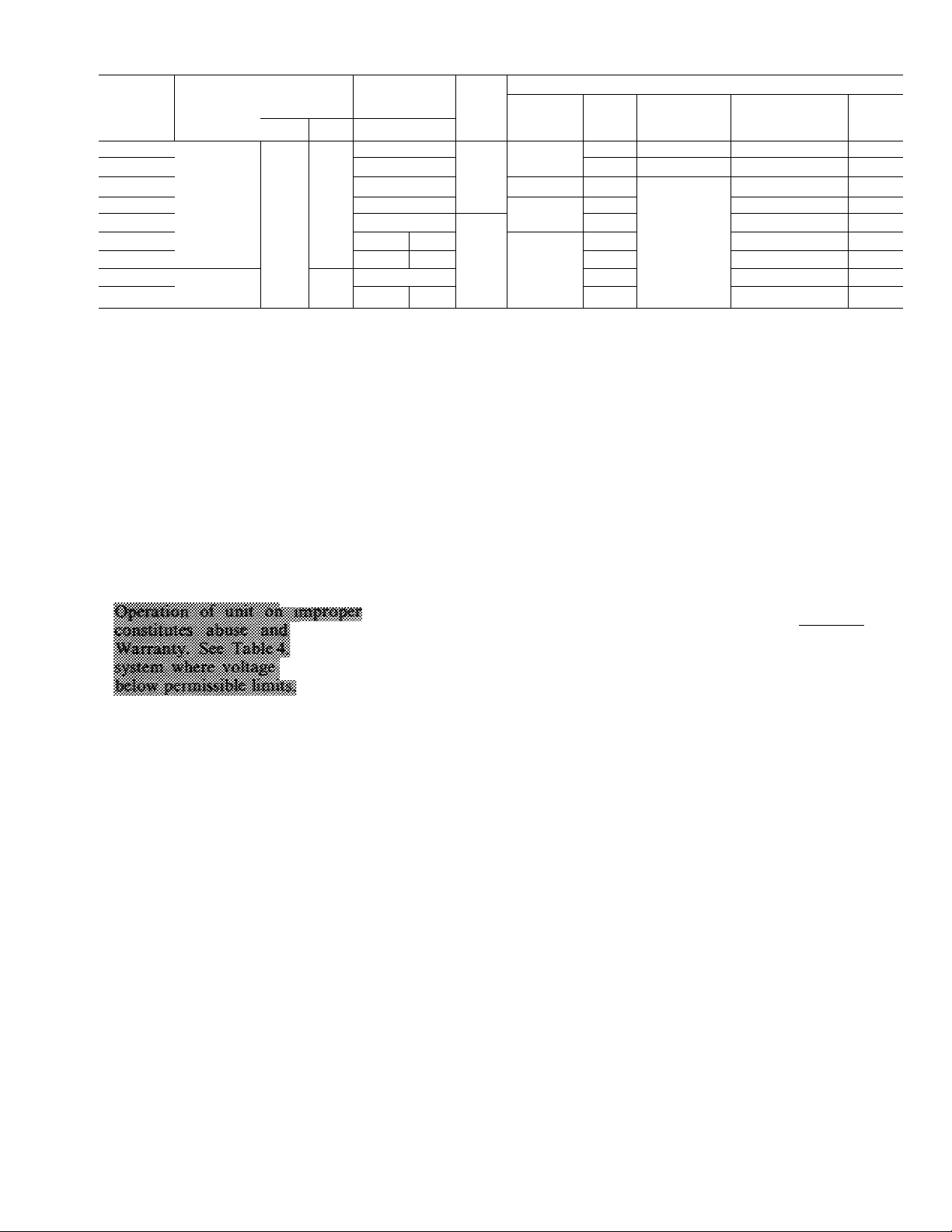
Table 4 — Electrical Data
COND
UNIT
38EB
015300 35 0 1
018300 41 0 9 1
024300
030310
036310 254
042360 108 0 21 7
048310 145 0 25 7
048350
060350
V/PH
208-230/1
230/1
VOLTS*
Max
OPER
Min
197
207
COMPR
LRA RLA
59 0
69 0 ;
93 0: 20 2
105.57^
150 0 i
133;
16 2
22.9
35 3
7.4
FAN
FLA
1 25
24
Min Wire
Sizet
(AWG)
12 33
10
8
BRANCH CIRCUIT
Max
Wiret
Min Ground
Ft
34
28 12
42
34
45
41
50
30
Wire
Sizet
14
10
Max Fuse or
HACR Type
Ckt Bkr Amps**
15 10 5
20
30
35
45
50 29 5
60 34 5
50
60
MCA
12 7
17 9
21 5
27 7
31 0
46 5
AWG — American Wire Gage
FLA — Full Load Amps
HACR — Heating, Air Conditioning and Refrigeration
LRA — Locked Rotor Amps
MCA — Minimum Circuit Amps
RLA — Rated Load Amps
^Permissible limits of the voltage range at which the unit will
operate satisfactorily
Step 3 — Make Electrical Connections — Be
sure field wiring complies with local and national
fire, safety and electrical codes, and that voltage to
unit is within limits shown in Table 4. Contact local
power company for correction of improper line
voltage.
cöüiti afleci Csmer
Do »ot ana ia
mäy niíOaaio above m
See Table 4 for recommended wire and fuse sizes.
When making electric connections, provide clear
ance at unit for refrigerant piping connections.
INSTALL A BRANCH CIRCUIT DISCONNECT
PER NEC of adequate size to handle unit starting
current. Locate disconnect within sight from and
readily accessible from the unit, per section 440-14
of National Electrical Code (NEC).
ROUTE LINE POWER LEADS INTO UNIT —
Extend leads from disconnect thru power wiring
hole provided (see Fig. 1) and into unit splice area.
Remove top cover to gain access to unit wiring.
CONNECT GROUND LEAD AND POWER
WIRING — Connect ground lead to a ground lug
in control box for safety. Then connect power wiring.
fCopper wire sizes based on 60 C Use copper or copper-clad
aluminum wire only Use latest NEC requirements for copperclad aluminum conductor sizing
^Required when using nonmetallic conduit
“Maximum dual element size
NOTE Control circuit is 24v on all units and requires external
power source
— GROUND LEAD-|-[1]GR0UNDING LUG
I-PHASE
CONN. TO
DISCONNECT
PER NEC
Splice Connections
-------------
------------- Factory Wiring
Field Wiring
------
BLK
-YEL-
1-PHASE
COND UNIT
-----------
Fig. 4 — Line Power Connections
See Fig. 4. Splice line power leads to yellow and
black pigtails. Use wire nuts and tape at each con
nection. Connect unit wiring to copper or copperclad aluminum power wiring. Do not connect to
aluminum wiring.
CONNECT CONTROL POWER WIRING —
Route 24-v control wires thru control wiring hole
and connect to pigtails supplied with unit (Fig. 1).
Splice control leads to black and blue pigtails on all
units. See Fig. 5.
Use furnace or fan coil transformer as 24-v (40-va
minimum) supply for system as shown in Fig. 5, or
use accessory transformer shown in Table J.
Page 6
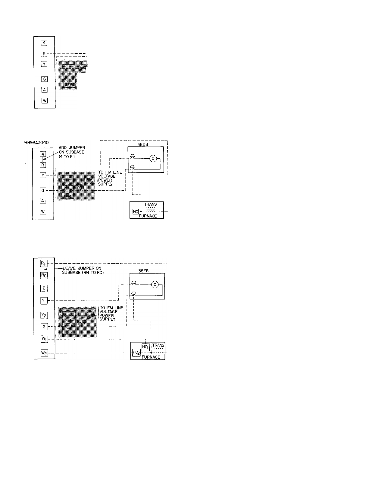
THERMOSTAT SUBBASE
HH93AZ042 OR
HH93AZ040
THERMOSTAT SUBBASE
38EB
I
-j
TO IFM LINE
VOLTAGE
:}“\POWER
SUPPLY
TRANS
ARRANGEMENT A-(COOLING ONLY)
“©n
START-UP
1. Backseat (open) liquid and suction line service
valves.
2. Set thermostat selector switch at OFF.
3. Set room thermostat at desired temperature.
Be sure this temperature is below indoor ambient.
4. Close electrical disconnects energizing entire
system.
5. Set room thermostat at COOL and fan switch at
FAN or AUTO, as desired. Operate unit for 15
minutes; then check system refrigerant charge.
See Refrigerant Charging, below.
Motors and controls are designed to operate satis
factorily in the voltage range shown in Table 4. If
necessary to use manifold gages for servicing, refer
to Carrier Standard Service Techniques Manual,
Chapter 1, Refrigerants, page 1-5, Fig. 8 for bypass
method of returning charge to system. Removal of
liquid line charging hose without following these
precautions could result in some loss of charge.
Refrigerant Charging
ARRANGEMENT B-ONE TRANSFORMER
(COOLING AND ONE-STAGE HEATING)
THERMOSTAT SUBBASE
HH93AZI76
ARRANGEMENT C-ONE TRANSFORMER
(COOLING AND TWO-STAGE HEATING)
IFR, FS and IFM are located in furnace on heating-cooling
applications If accessory IFR is required for cooling-only
‘Connect FS to low-speed indoor fan terminal when 2-speed fan
C — Contactor (12-va) Trans — Transformer
FS — Fan Switch
HC — Heating Control Field Splice
IFM — Indoor Fan Motor
IFR — Indoor Fan Relay
NOTE Refer to unit wiring label for wire colors: C to G and C to Y
connections
applications, locate (IFR) in fan coil
is used
________
________
Field Wiring
Factory Wiring
>• Fig. 5 — Control Circuit Connections
CAUTION: To
Do sot morchsrge sysiiem. As ovorcbsf®e
cas
Condensing units contain correct operating
charge for complete system when connected to
Carrier-approved evaporators of same capacity as
condensing unit with 25 ft or less of Carrier accessory
tubing or field-supplied tubing of recommended
size. For every 10 ft of liquid line of recommended
size over 25 ft, add refrigerant charge as follows: .41b
for 3/8-in. line; .28 lb for 5/ 16-in. line. On all other
systems, adjust charge for correct operation as
applicable.
Service port connections are provided on liquid
and suction line service valves for evacuation and
charging. See Fig. 1.
TO CHECK, ADJUST OR REPLACE REFRIG
ERANT CHARGE use method recommended in
Table 6. Details of charging methods are listed
below.
Before recharging system, thoroughly evacuate
system and then weigh in refrigerant charge speci
fied in Table 5. Check or adjust charge as required.
Refer to Carrier Standard Service Techniques
Manual, Chapter 1, Refrigerants, for additional sys
tem evacuation and dehydration instructions.
WEIGHT METHOD — Refer to Table 5 or unit
nameplate for correct system refrigerant charge.
Remove any refrigerant remaining in system before
recharging.
Page 7
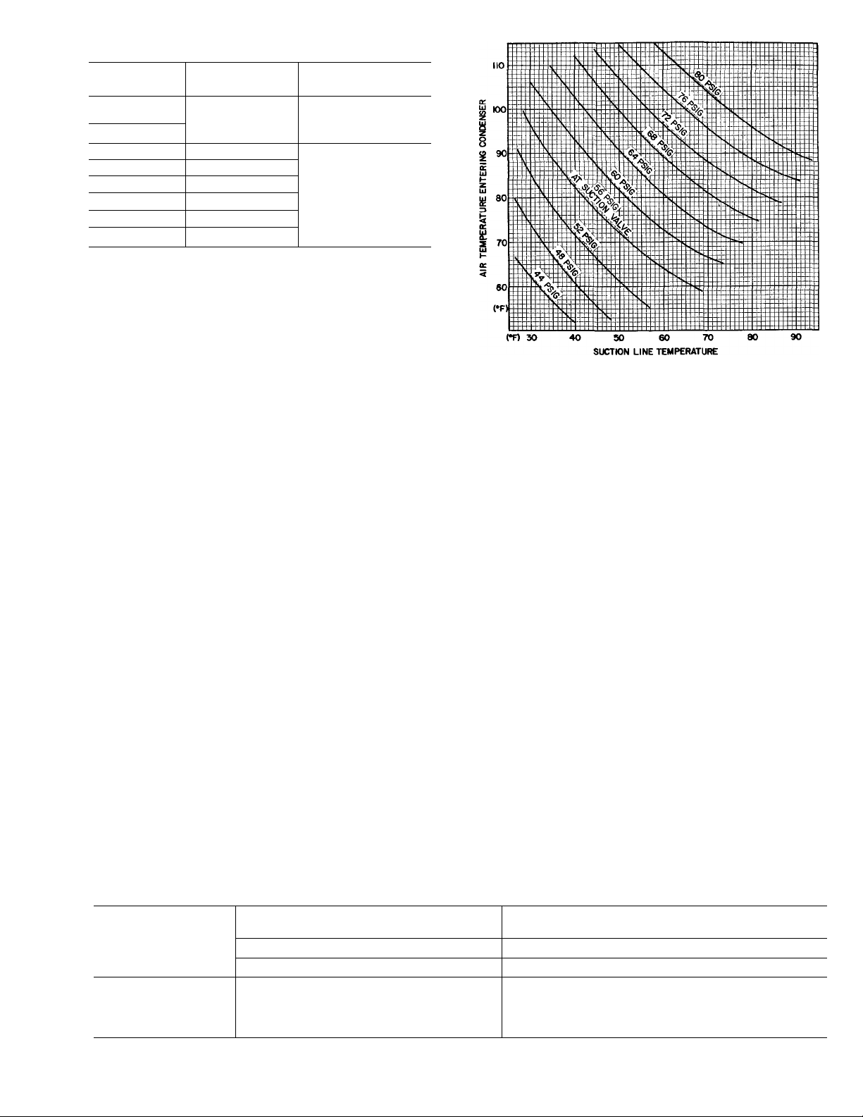
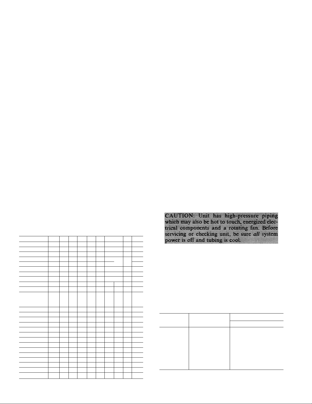
Table 5 — Service Data
UNIT
38EB
015300
018300
024300
030310
036310 7 5
042360 6 3
048310
048350
060350
‘Factory refrigerant charge is adequate when evaporator and
condensing unit are the same size and are connected with 25ft
or less of field-supplied tubing of recommended size or Carrier
accessory tubing
R-22 CHG‘
(lb)
3 3
5 3
6 1
7 2
9 6
CONDENSER
FAN RPM
1110
1075
When system is not evacuated, subtract the
following amount from total charge.
38EB015 thru 030 — .10 lb (1.6 oz)
38EB036 thru 060 — .20 lb (3.2 oz)
The Dial-a-charge charging cylinder is an accu
rate device used to recharge system by weight. These
cylinders are available at refrigeration supply firms.
CHARGING CHART METHOD — Use Charging
Chart, Fig. 6, and the following procedure.
1. Operate unit a minimum of 10 minutes before
checking charge.
2. Measure suction pressure by attaching a gage to
suction valve service port.
3. Measure suction line temperature by attaching a
service thermometer to unit suction line near suc
tion valve. (Insulate thermometer for accurate
readings.)
4. Measure outdoor (condenser inlet) air dry-bulb
temperature with a second thermometer.
5. Refer to Charging Chart (Fig. 6). Find air tem
perature entering condenser and project hori
zontally to curve showing suction pressures
(psig at suction valve).
6. From this interseetion, project vertically down
ward to suction line temperature.
Fig. 6 — 38EB Charging Chart
(AccuRaterT"'' System)
7. If unit has a higher suetion line temperature than
charted temperature, add refrigerant until
charted temperature is reached.
8. If unit has a lower suction line temperature than
charted temperature, bleed refrigerant until
charted temperature is reached.
9. If air temperature entering condenser or pressure
at suction valve changes, charge to new suction
line temperature indicated on chart.
CHARGEMASTER® METHOD — Operate unit
for 10 minutes before using Chargemaster (Carrier
Part No. 38GC680004).
1. Tape Chargemaster feeler bulb to suction line
close to condensing unit. Insulate bulb. Ensure
suction line is clean for good contact with bulb.
(Uninsulated bulb or dirty suction line will seri
ously affect accuracy of temperature readings.)
2. Connect refrigerant drum to Chargemaster inlet
port keeping drum in position for vapor charging.
Table 6 — Refrigerant Charging Methods
METHODS OF CHECKING OR
COND UNIT
38EB System Refrigerant Control
ALL
‘Sight glass field supplied and installed In liquid refrigerant line.
ADJUSTING CHARGE
Non TXV j
Chargemaster® |
or 1
Charging Chart 1
TXV
Sight
Glass‘
METHODS FOR COMPLETE
System Refrigerant Control
Non TXV
Weight Method
plus
Chargemaster or
Charging Chart
RECHARGING
1 TXV
Weight Method
1 plus
1 Sight Glass*
Page 8
3. Connect Chargemaster outlet port to unit suction
valve service port.
4. Crack valves on refrigerant drum and Chargemaster to purge lines from drum to suction valve.
After purging lines, close valve on Chargemaster
only.
5. Measure outdoor air dry-bulb temperature.
6. Crack unit suction valve and read evaporator
temperature at red needle position on Chargemaster temperature gage and suction line tem
perature at black needle position.
1. Énter Chargemaster Charging Chart, Table 7, at
outdoor air temperature (step 5) and evaporator
temperature (step 6). Find the suction line tem
perature required for correct system charge. If
actual suction line temperature (step 6) is higher
than table value, the system is undercharged. If
suction line temperature is lower than table
value, system is overcharged.
EXAMPLE: At outdoor air temperature of 84 F
and evaporator temperature of 43 F, the system
will be correctly charged at 76 F ± 2 F suction
line temperature. See Table 7.
8. Add charge by slowly opening Chargemaster
valve. If necessary, reduce charge by bleeding at
liquid line service valve. Check outdoor air and
evaporator temperature during procedure. If they
change, refer back to Chargemaster Charging
Chart.
Correct use of Chargemaster ensures that an opti
mum refrigerant charge will be in system when con
ditions and system components are normal.
However, the Chargemaster does not solve or fix
system abnormalities. It indicates correct charge for
condition of the system. It will not make corrections
for dirty filters, slow fans, excessively long or short
suction lines or other abnormal conditions. This
charging device ensures that a correct relationship
exists between outdoor temperature, evaporator
temperature, and suction line temperature on a spe
cific system.
SIGHT GLASS METHOD — (Field-supplied sight
glass installed in liquid line.) A satisfactory oper
ating charge can be obtained on thermal expansion
valve systems only by charging to a clear sight glass.
For optimum charge, increase high-side pressure to
380 ± 10 psig by blocking condenser fan discharge
or air entering condenser. Charge to a clear sight
glass while holding constant high-side pressure. For
peak efficiency, adjust charge to yield a liquid refrig
erant temperature at the evaporator that is approxi
mately the same as outdoor dry-bulb temperature.
r
Table 7 — 38EB Chargemaster® Charging
Chart (AccuRater™ System)
OUTDOOR
TEMP
(F)
60
62 30 38
64
66
68
70 32 41 52 64
72 31
74 30
76
78
80
82
86
88
90 34 42
92
94 39 47
96 38 45
98 36
100
102 41
104 39 46
106 45
108 43
110
112
114
Example
EVAPORATOR TEMPERATURE (F)
2TT25l^l3TT34T37^
SucüônUnëT^^ (f )
32
28
27
40
37
35
34
29
27
26
51
3ê
47 60
57
45
54 67
43
39 50 61
37
48
46 56 66
36
44 54
35
33 42
32
40
*
375046
29
35
33
58 69
52
44
41
72 1
63
61 72
596568
53
51
49
44
42 49
ta
ta
ta
75
63
61
59
57
55
53
51
48 55
41
m
73 85
70
81
68 78 90
65 75 86
72 83
63
61
70 80
59 67 77
57 65 75
63
53 61 70
51 59 68
49 57 65
47
55 63
46 53
50 59
SERVICE
Compressor Removal — See Table 8 for com
pressor information and Fig. 7 for component loca
tion. Shut off power to unit. Remove refrigerant
from unit using refrigerant removal methods de
scribed in Carrier Standard Service Techniques
Manual, Chapter 1, Refrigerants. Be sure system
pressure is 0 psig before attempting compressor
removal.
■ Table 8 — Compressor Data
UNIT
38EB
015301 AJ8516G
018301 AJ8520G
024301
73
61
030301
036301
042361 AV5542E
048311
048351 PC5016BD
060351 PC6416AG
‘Refer to Carrier Service Parts Catalog for replacement model
numbers
fWhere piping exceeds 50ft, contact your local Carrier distributor
PRODUCTION
COMPR*
CRD1-0200PFV
CRF1-0250PFV 55
CRJ1-0300PFV 55
YRD-0400-PFV 72
OIL CHARGE (oz)t
Initial Recharge
26 24
26 24
55 51
54
66 62
66 62
51
51
50
68
Page 9
SUCTION LINE HOT GAS DISCHARGE LINE
.CONDENSER COIL
\ \ £8í№mw Í
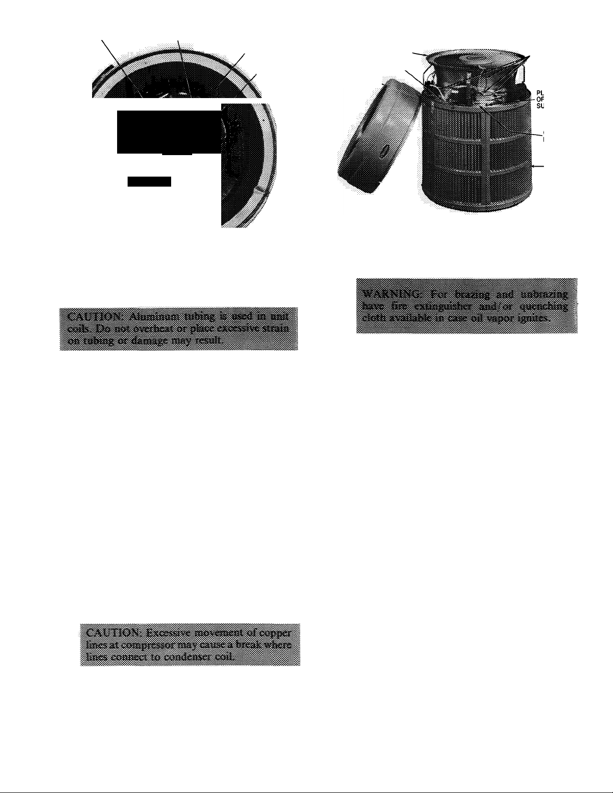
Fig. 7 — Condensing Unit 38EB Component Locations
Follow safety codes. Wear safety glasses and
work gloves. Have quenching cloth available.
COMPRESSOR
DISCHARGE GRILLE (FAN
MOTOR UNDERNEATH)"
WIRE ACCESS OPENING
TOP COVER
FAN MOTOR
AND
COMPRESSOR
LEADS
1. Remove top cover by loosening 6 screws around
unit and 2 screws in connector plate. Lift cover
straight up.
2. Disconnect high- and low-voltage field wiring
and fan motor leads from capacitor and
contactor.
3. Remove 4 screws holding discharge grille in
place. Lift grille from unit.
4. Disconnect compressor leads (crankcase heater,
low-pressure switch, if so equipped) from elec
trical components and pull them thru the wire
access opening into the coil section. Lift fan
orifice/control ring after pinching and pressing
down on 3 plastic pins of tube supports.
5. Remove louvered casing by taking out 16 screws
securing it to the cabinet and sliding it away
from the coil.
6. Using a midget tubing cutter, cut liquid and
discharge lines on the coil and suction line at a
convenient place for easy reassembly with
copper slip couplings.
7. After plugging connections, remove condenser
coil by pinching plastic pins of tube supports
that extend into basepan and lift vertically. Set
coil on a clean, flat surface.
8. Remove compressor holddown bolts and slide
out compressor. Remove crankcase heater, if
so equipped.
9. Carefully unbraze suetion and discharge line
piping stubs from compressor after noting posi
tion of stubs to assist when reinstalling.
10. Install new compressor, placing crankcase
heater around compressor, if so equipped. Be
sure compressor holddown bolts are in place.
11. Replace coil; braze suction and discharge lines
to compressor piping stubs (at points where cut.
Step 6); rewire compressor and leak test.
12. Replace fan orifice/control ring; connect com
pressor wires after feeding them thru control
ring; replace fan/grille assembly and rewire;
connect high- and low-voltage power wiring;
and replace louvered casing.
13. Replace top cover by running screws into orifice
loosely and tighten when cover is in place.
14. Evacuate and recharge system.
Filter Drier — Install field-supplied filter drier
(Table 3) in system liquid line when refrigerant
system is opened for serviee as described under
Compressor Removal. Position drier in liquid line
at convenient location.
Pumpdown Procedure — The system may be
pumped down in order to make repairs on low side
without losing complete refrigerant charge.
1. Attach pressure gage to suction service valve gage
port.
2. Frontseat the liquid line valve.
3. Start unit and run until suction pressure reaches
5 psig (see Caution).
4. Shut unit off and frontseat suction valve.
5. Vent remaining pressure to atmosphere.
Page 10
Unit Controls and Safety Devices
HIGH-PRESSURE RELIEF VALVE is located in
compressor. Relief valve opens if system operating
pressure differential between suction and discharge
pressure reaches 400 to 500 psi on all models.
LOW-PRESSURE SWITCH (015 and 018 models
only) is located on unit suction line. Low-pressure
switch settings are: cutout, 31 ±4psig; cut-in. 60
(+15, -0) psig.
INTERNAL TEMPERATURE AND/OR CUR
RENT SENSITIVE OVERLOADS reset automati
cally when motor internal temperatures drop to a
safe level (overload may require up to 30 minutes to
reset). When internal overload is suspected of being
open, check by using an ohmmeter or continuity
tester. If necessary, refer to Carrier Standard Serv
ice Techniques Manual, Chapter 2, Electrical, for
complete instructions.
INHERENT FAN MOTOR PROTECTION pro
tects motor from abnormal current and temperature.
SOLID-STATE TIME GUARD II CIRCUIT,
if so equipped, protects unit compressor by prevent
ing short cycling. Time Guard II circuit provides a
5 ± 2-minute delay before restarting compressor
after shutdown for any reason. On normal start-up,
the 5-minute delay occurs before thermostat closes.
After thermostat closes, the Time Guard II circuit
then provides a 3-second delay to prevent contactor
chattering.
CRANKCASE HEATER (when equipped) — The
purpose of the heater is to keep the crankcase warm
during the off cycle and thus prevent dilution of
the oil with refrigerant. This assures good lubrica
tion and prevents loss of oil from crankcase during
start-up.
CRANKCASE HEATER RELAY deactivates
heater when compressor is operating for maximum
energy efficiency.
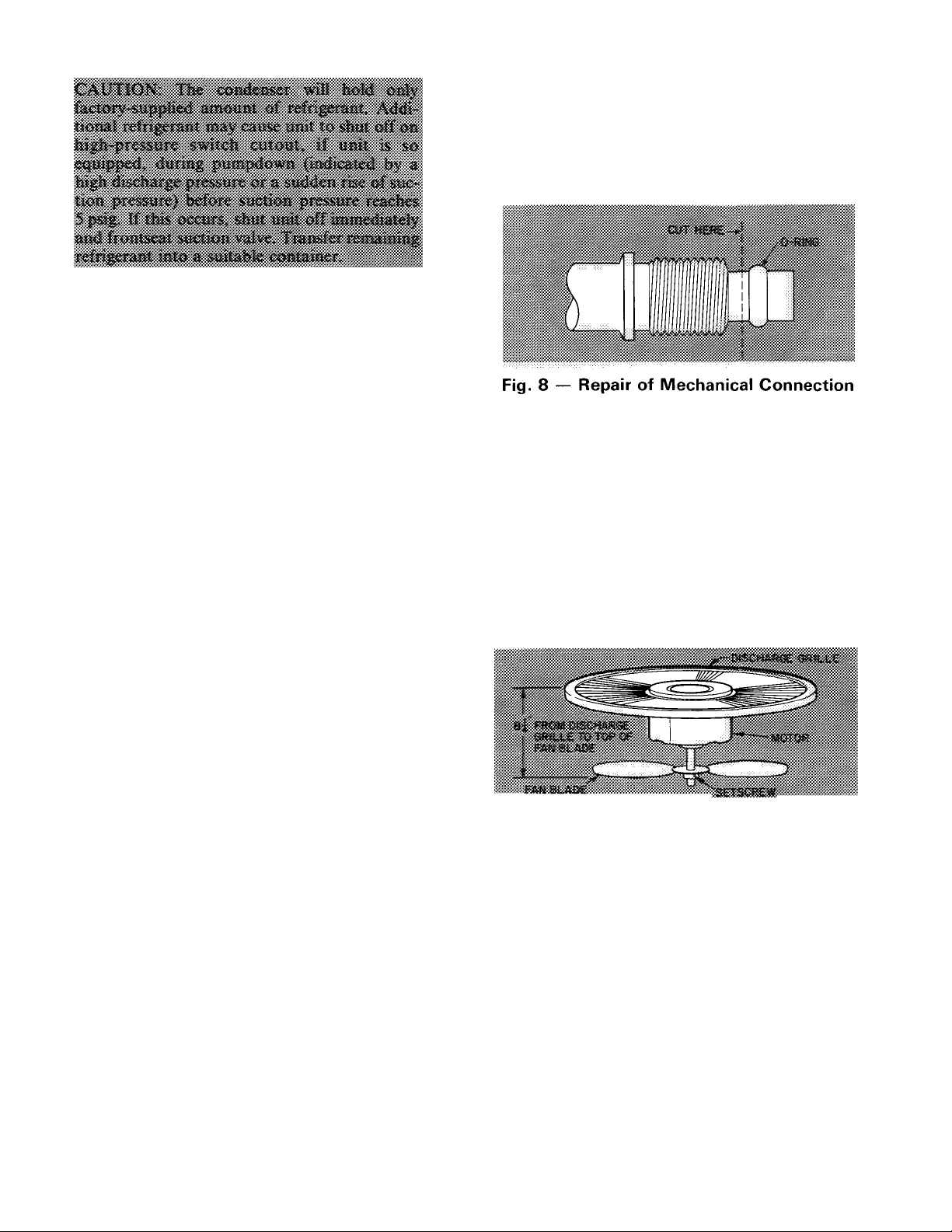
Compatible Fitting Repair
MECHANICAL CONNECTION — Frontseat unit
service valves. Relieve refrigerant pressure from
tubing. Back off locknut from Compatible Fitting
onto tube. Cut fitting between threads and O-ring
as shown in Fig. 8. Remove tubing section remain
ing in threaded portion of fitting. Discard locknut.
Clean, flux, and insert new tube end into remain
ing portion of Compatible Fitting. Wrap valve base
in wet rag. Heat and apply low-temperature (430 F)
solder.
SWEAT CONNECTION — Frontseat unit service
valves. Relieve refrigerant pressure from tubing.
Clean and flux area around leak. Repair using low-
temperature (430 F) solder.
Evacuate or purge evaporator coil and tubing
system. Add refrigerant charge. See Refrigerant
Charging instructions described previously.
Condenser Fan Adjustment — Required fan
position is shown in Fig. 9. Adjust fan by loosening
setscrew(s) and moving fan blade up or down.
ÎtAAAAfAfVAWA'.
Fig. 9 — Condenser Fan Position
Condenser Fan Motor Removal
1. Shut off power to unit. Failure to do so may
result in electric shock or injury from rotating fan
blade.
2. Remove top cover by loosening 8 screws and
lifting straight up.
3. Disconnect fan motor leads from control leads.
See Fig. 7.
4. Remove 4 screws holding fan motor/discharge
grille in place and lift assembly from unit.
5. Remove Carrier nameplate by straightening
tabs.
6. Remove 4 nuts holding fan motor to discharge
grille. Remove motor and leads.
7. Reassembly is reverse of above procedure. Make
sure fan is positioned correctly as in Fig. 9.
10
Page 11
MAINTENANCE
-^Lubrication
COMPRESSOR contains factory oil charge. Re
place oil when lost. See Table 8 for oil recharge and
refer to Carrier Standard Service Techniques
Manual, Chapter 1, page 1-21, for oil recharging
procedure. Use Carrier PP33-1, Texaco WFI-32 or
Suniso 3GS oil.
FAN MOTOR BEARINGS are prelubricated for 3
years heavy duty or 5 years normal duty. When
lubrication is necessary, send motor to authorized
motor repair shop.
^ Coil Repair — A flare-union coupling repair kit
is available, with instructions, thru Carrier Service
Parts.
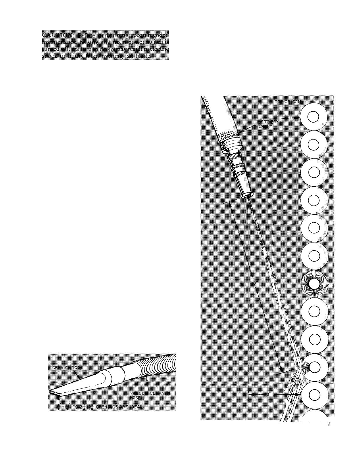
Coil Cleaning to be done at the beginning of
each cooling season or more often if required.
5. Using garden hose, spray coil vertically down
ward with a constant stream of water at moderate
pressure (see Fig. 11). Keep nozzle at a 15 to 20
degree angle, about 3 in. from coil face and 18 in.
from tube. Spray so debris is washed out and
away from coil.
6. Reinstall louvered casing being careful not to
damage coil.
7. Restore power to unit.
Follow iliese stì«€niciìom corttfoHy, Coniaci
1. Shut off power to unit.
2. Remove louvered casing by taking out 16 screws
securing it to the cabinet and sliding it away from
the coil.
3. Clean coil using vacuum cleaner and its crevice
tool (see Fig. 10). Work crevice tool vertically
making sure tool only touches dirt on fins. To
prevent fin removal, do not “scrub” fins with tool
or move tool horizontally.
4. If oil deposits are present, spray coil with house
hold detergent (Fantastic, Lestoil, 409, or any
similar type). Wait 10 minutes then proceed to
step 5.
Fig. 10 — Crevice Cleaning Tool
11
Fig. 11
f n
Positioning Hose to Spray Coil
Page 12

TROUBLESHOOTING GUIDE
SYMPTOM AND
PROBABLE CAUSE
COMPRESSOR SHUTS OFF. FAN OVERLOAD
OR HIGH-PRESSURE SWITCH CUT OUT, OR
INTERNAL PRESSURE RELIEF OPENS
Condenser Fan On
1. Condenser air restricted or recirculating.
2. Refrigerant overcharge; noncondensables in
system; system restricted.
3. Improper line voltage, loose electrical connec
tions, faulty run capacitor.
Condenser Fan Off
1. Fan slipping on shaft, fan motor bearing stuck,
fan motor defective.
2. Loose electrical connections. Fan motor over
load open.
COMPRESSOR RUNS BUT COOLING IS INSUFFICIENT
1. Low refrigerant charge.
2. Dirty filters, partially restrict airflow (evaporator
coil may be partially iced).
High Suction Pressure
1. Defective compressor valves (accompanied by
low head pressure).
COMPRESSOR SHUTS OFF FROM
LOW-PRESSURE SWITCH CUTOUT
Evaporator Fan Runs
1. Low refrigerant charge or restricted evaporator
air.
2. Restricted refrigerant flow.
' Evaporator Fan Stopped
1. Evaporator fan-motor defective or inoperative.
PROBABLE REMEDY
1. Condenser coil blocked. See Maintenance, Coil
Cleaning. Check airflow clearance (Fig. 1).
2. Review Refrigerant Charging procedures; purge
system, replace filter drier, check refrigerant
control.
3. Review Installation, Step 3; replace capacitor.
1. Tighten fan hub setscrews, see Condenser Fan
Motor Removal.
2. Check unit wiring. Check motor bearings. Re
place motor.
1. Check Refrigerant Charging procedures.
2. Check evaporator air system for dirty filters,
obstruction in ductwork, improper damper
settings. Refer to coil, fan coil or furnace
instructions as applicable.
1. Perform Compressor Replacement procedure.
Recheck system charge.
1. See Compressor Runs But Cooling Is Insufficient
above regarding filters, ductwork, etc.
2. Check refrigerant flow device, be sure correct
AccuRater^^'^ or TXV is used.
1. Check furnace or fan instructions regarding de
fective fan relay, belt adjustment, condition of
motor bearings and overloads, check and tighten
electrical connections, check power supply.
COMPRESSOR SHUTS OFF,
WILL NOT RESTART
Contactor Open
1. Burned out transformer, open thermostat circuit,
faulty control relay, open overload.
Contactor Closed or Closes Then Opens
1. Compressor power is out, compressor motor is
burned out or internal overloads are open. Time
Guard II circuit faulty.
For replacement items use Carrier Specified Parts
Manufacturer reserves the right to discontinue, or change at any time, specifications or designs without notice and without incurring obligations
1 4
Book
Tab 3a 2a
Form38EB-3SI Supersedes 38EB-2S1,
38EB001and38EB002
1. Check control circuit components and wiring.
Refer to unit label diagram, check all conditions.
Refer to Standard System Techniques Manual,
Chapter 2, Electrical.
1. Check main power supply wiring. Refer to Elec
trical Data table and label diagram. Substitute
Time Guard II with a replacement to verify its
operation. Refer to Standard Service Techniques
Manual, Chapter 2, Electrical.
Printed in U S A.
6-82
PC 101
Catalog No 533-879
 Loading...