

Manufacturer reserves the right to discontinue, or change at any time, specifications or designs without notice and without incurring obligations.
PC 111 Catalog No. 533-80098 Printed in U.S.A. Form OM38/40-4 Pg 1 4-03 Replaces: New
Book 1 4
Ta b 3 e 2 f
OWNER’S MANUAL
38BNB,BNE018-036
40BNB,BNE018-036
Cooling Only and Heat Pump Duct-Free High Wall Systems
CONTENTS
Page
INTRODUCTION . . . . . . . . . . . . . . . . . . . . . . . . . . . . . . . . . 2
GENERAL. . . . . . . . . . . . . . . . . . . . . . . . . . . . . . . . . . . . . . .2,3
OPERATING MODES . . . . . . . . . . . . . . . . . . . . . . . . . . . . 2
REMOTE CONTROL. . . . . . . . . . . . . . . . . . . . . . . . . . . . . 2
OPERATION . . . . . . . . . . . . . . . . . . . . . . . . . . . . . . . . . . . 3-7
REMOTE CONTROL OPERATION . . . . . . . . . . . . . . . . 3
UNIT OPERA TION. . . . . . . . . . . . . . . . . . . . . . . . . . . . . . . 7
CLEANING AND MAINTENANCE . . . . . . . . . . . . . . .8,9
AIR FIL TERS. . . . . . . . . . . . . . . . . . . . . . . . . . . . . . . . . . . . 8
Page
INDOOR UNIT FRONT P ANEL . . . . . . . . . . . . . . . . . . . 8
INDOOR UNIT COIL . . . . . . . . . . . . . . . . . . . . . . . . . . . . 8
OUTDOOR UNIT COIL . . . . . . . . . . . . . . . . . . . . . . . . . . 8
CONDENSATE DRAINS . . . . . . . . . . . . . . . . . . . . . . . . . 8
SYSTEM OPERATION CHECK LIST . . . . . . . . . . . . . . 9
DIP SWITCH SETTINGS . . . . . . . . . . . . . . . . . . . . . . . . . 9
ENERGY SAVING RECOMMENDATIONS. . . . . . . . . 9
TROUBLESHOOTING GUIDE . . . . . . . . . . . . . . . . 10-12
I
I
I
I
MODE AN SWEEP
AA
START
STO
P
1 2 3 SLEEP
DA LY
2
INTRODUCTION
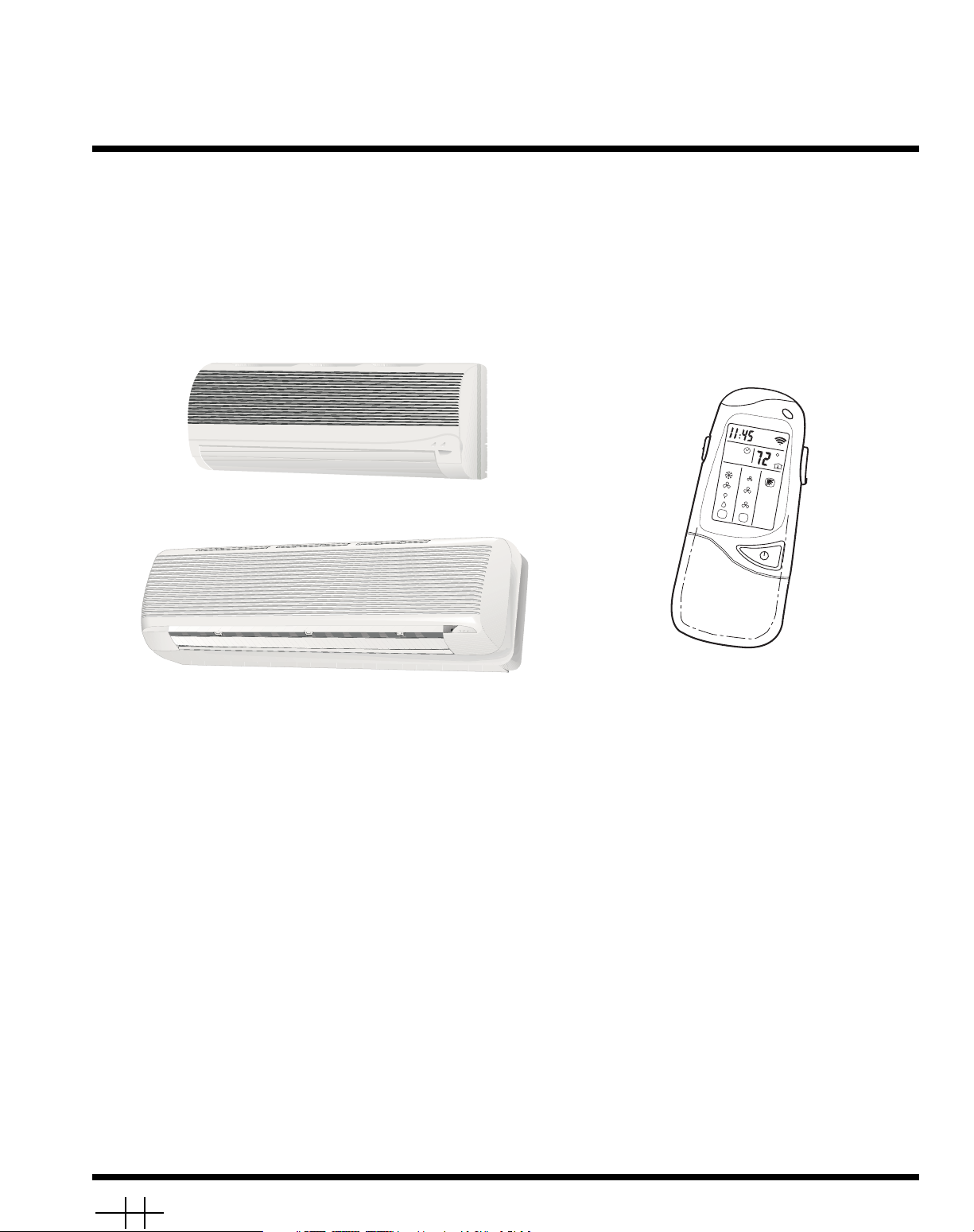
Thank you for choosing a Streamline® Duct Free System.
The same pride in craftsmanship and engineering knowledge
that goes into equipment cooling the Astrodome in Texas, the
Sistine Chapel in Rome, the U.S. Capitol Hall of Congress, and
thousands of other installations worldwide has gone into the
construction of this unit.
Duct Free Systems provide quiet, maximum comfort. In addition to cooling and/or heating, the Duct Free System will filter and dehumidify the air in the room to provide maximum
comfort.
GENERAL
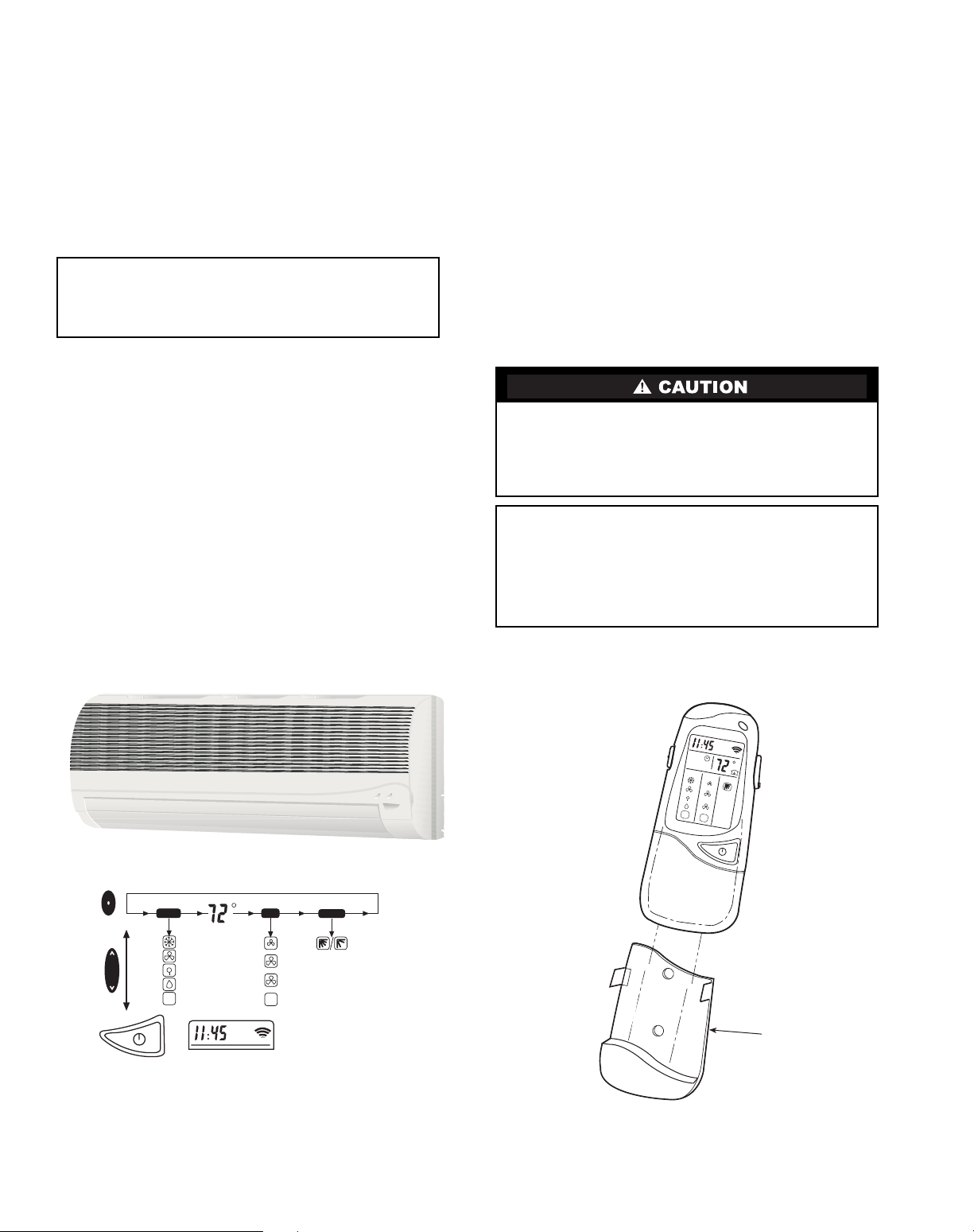
The Duct Free System can be set up and operated from the
remote control (provided). See Fig. 1. If the remote is misplaced, the system can be operated from the “Auto” setting on
the unit.
Operating Modes — The duct free system has 5 operat-
ing modes:
• Cooling
•Fan Only
• Heating (if applicable)
• Dehumidification
• Auto
COOL ING — In Cooling mode, the system cools, dries and
filters room air.
FAN ONLY — In Fan Only mode, the system filters and circulates room air without changing room air temperature.
HEATING — In Heating mode, the system heats and filters
room air.
DEHUMIDIFICATION — In Dehumidification mode, the
system dries, filters and slightly cools room air temperature.
This mode does not take the place of a dehumidifier .
AUTO — In Auto mode, the system will automatically cool or
heat room air according to a selected temperature (set point).
If temperature of room air is lower than set point, the system
will operate in Heating mode. If temperature of room air is
higher than set point, the system will operate in Cooling mode.
Remote Control — The remote control transmits com-
mands to set up and operate the system. The controller has a
window display panel that shows the current system status. The
controller can be secured to a surface when used with the
mounting rack provided. See Fig. 1.
IMPORTANT: Duct Free Systems should be installed by
authorized personnel only, using approved tubing and
accessories. If technical assistance, service or repair is
needed, contact the installer or call 1-800-227-7437.
Handle the controller with care and avoid getting the controller wet. Damage to the device may result.
Do not leave remote control in a drawer or near a warm/hot
appliance as the system will try to cool the environment
around the controller .
IMPORTANT: The remote control and unit continually
exchange information regarding room air temperature.
When operating the remote control from the mounting
rack, be sure there is a direct line of sight between the
controller and the unit. The controller can operate the
unit from a distance of up to 23 ft as long as there are not
any obstructions.
I
I
I
I
I
I
MODE FAN SWEEP
AA
START
STOP
1 2 3 SLEEP
DAI Y
REMOTE CONTROL
MOUNTING RACK
MODE
I
I
I
I
I
I
I
I
A
COOLING
FAN
HEATING FUNCTION
DRY
AUTO
FAN
A
LOW
MEDIUM
HIGH
AUTO
SWEEP
SWEEP
ON/OFF
UP
DOWN
MODE
BUTTON
UP/DOWN
BUTTON
ON/OFF
BUTTON
Fig. 1 — Duct Free System
REMOTE CONTROL BUTTONS —
PROGRAMMING OPTIONS
3
The remote control can perform the following functions:
• Turn the system ON and OFF
• Select operating mode
• Adjust room air temperature and fan speed
• Set time periods for automatic system operation
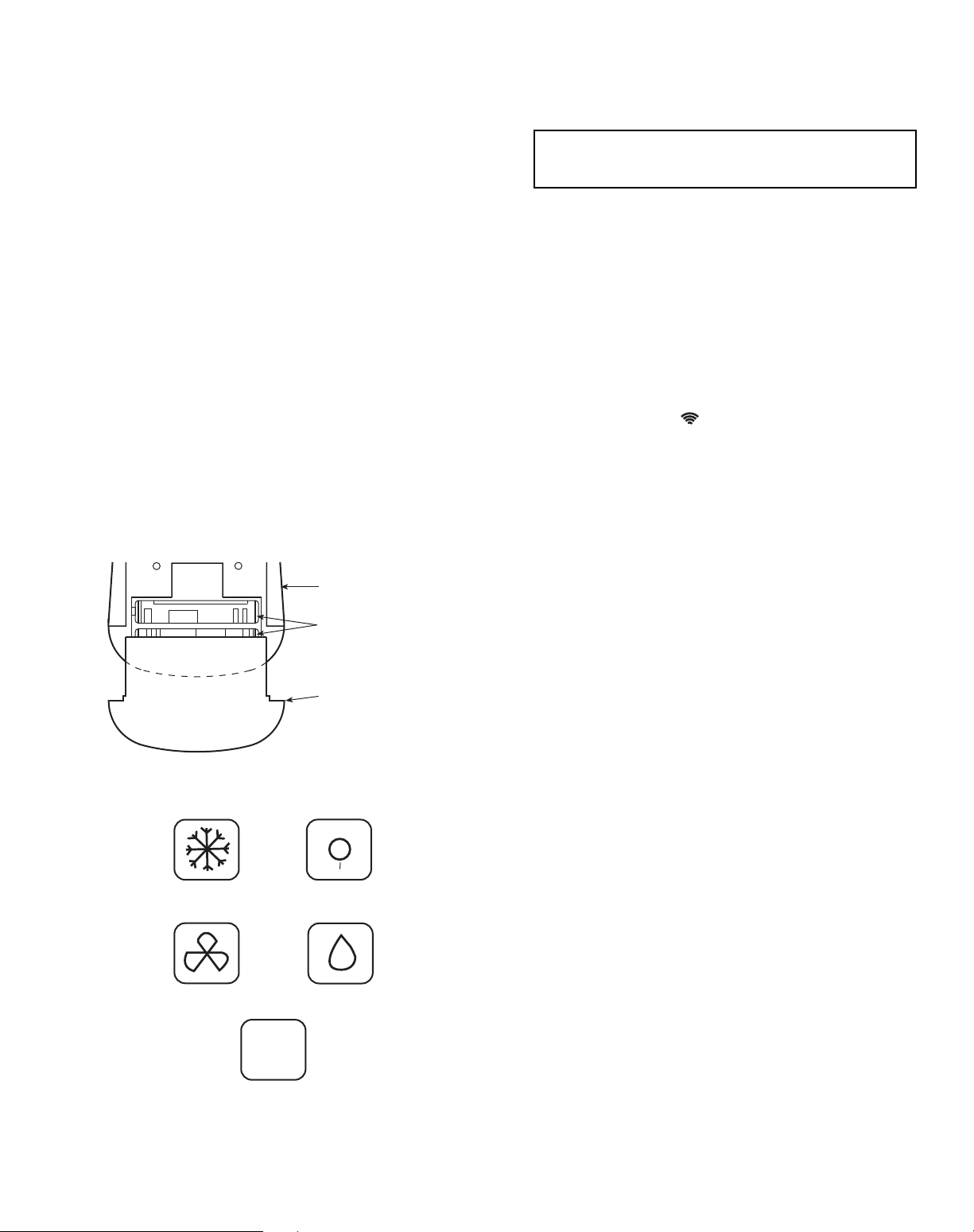
BATTERY INSTALLATION — Two AAA 1.5V alkaline
batteries (included) are required for operation of the remote
control. See Fig. 2 for battery location.
T o install batteries:
1. Remove battery compartment cover by sliding off of
remote.
2. Insert batteries being sure to follow polarity markings inside battery compartment.
3. Replace battery compartment cover.
NOTE: Replace batteries whenever “Low battery” indicator
appears on remote control display panel.
DISPLAY SCREEN — There are five operating mode indicators that appear on the remote control display screen. See Fig. 3.
OPERATION
Remote Control Operation —
The remote control
has 3 buttons (see Fig. 4) used for operating and controlling the
system:
• MODE button — changes operatin g mode
• UP/DOWN button — selects desired operating mo de
• ON/OFF button — turn s the system on or off and trans-
mits programing selections to unit.
NOTE: When transmitting a command from the controller to
the unit, be sure to point the controller toward the right side of
the unit. See Fig. 4. The unit will confirm receipt of a command by sounding 2 audible beeps.
FAN S PEED — To select the Fan mode and change the Fan
Speed, follow the steps below:
1. Press MODE button to select the Fan mode.
2. Pres s UP/ DOW N b ut ton to select desired fan sp eed o r
to Auto.
3. Press ON/OFF button to send changes to unit from remote control.
NOTE: If unit is operating in DEHUMIDIFICATION mode
the fan will only operate in Low speed and cannot be changed.
TEMPERATURE SETTINGS — The temperature settings
can be easily changed by pointing the controller toward the unit
and pressing the UP/DOWN button until desired temperature
appears on screen. The symbol appears each time the ON/
OFF button is pressed.
Another way of changing the temperature is as follows:
1. Select the temperature display by pressing the MODE
button. The degree symbol will flash next to the digits on
the screen.
2. Press UP/DOWN button to select the desired temperature. The available temperature range is from 54 F to
90 F .
3. Press ON/OFF button to send changes to unit from remote control.
AIRFLOW DIRECTION — Perform the following steps to
change the direction of airflow from the unit:
1. Press MODE button to select the Sweep function.
2. Press the top of the UP/DOWN button to move the air
deflector on the unit in an up and down motion. The airflow symbol displays motion.
3. Press the bottom of the UP/DOWN button. Th e a i r f l o w
deflector stops at a given angle. The airflow symbol display remains in a fixed position.
4. Press ON/OFF button to send changes to unit from remote control.
NOTE: If placing the air deflector in a fixed position is chosen,
the deflector stops at the angle in which it was located when
the ON/OFF button was pressed.
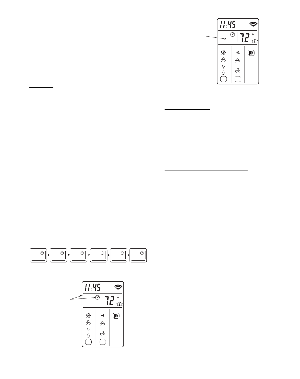
SETTING CLOCK
1. Slide down front cover of controller below ON/OFF button. See Fig. 4.
2. Press CLOCK button using the tip of a pen or paper clip.
See Fig. 5.
3. Press UP/DOWN button to set minutes.
4. Press MODE button. The hour digits will flash.
5. Press to UP/DOWN bu tton to set the hour.
6. To confirm current clock settings, press CLOCK button
once again using the tip of a pen or paper clip. The remote
control will automatically go back to previous display
and the clock is displayed.
IMPORTANT: If no changes are made within 10 seconds, the remote control will return to its previous
setting.
BACK OF
REMOTE CONTROL
2 AAA 1.5V BATTERIES
BATTERY COMPARTMENT
COVER
A
COOLING
HEATING
FAN ONLY
DEHUMIDIFICATION
AUTO
I
I
I
I
I
I
I
I
I
I
I
I
I
I
I
I
I
Fig. 2 — Location of Batteries on Remote Control
Fig. 3 — Operating Mode Indicators on
Remote Control

4
PROGRAMMING TIME PERIODS — The duct free system can be programmed to operate at desired levels. Be sure to
set the clock before programming the system.
• Increments of time are in 10-m inute intervals.
• The Timer Start/Stop indicator light on the unit is on
when a time period is set. See Fig. 4.
• The remote control displays the Start/Stop time of the
time period that is closest to the current time. If the unit
is ON, “STOP” and the time period is displayed. If the
unit is OFF, “START” and the time period is displayed.
Setting Start/Stop Time
— Timer feature is used to set unit
operation Start/Stop times. Three different time periods up to
10 hours apart and within 24 hours can be programmed using
this feature.
1. Slide down front cover of controller below ON/OFF button. See Fig. 4.
IMPORTANT: Be sure to point the remote control
toward the unit while pressing the TIMER or SET
buttons.
TEMPERATURE SENSOR
TRANSMISSION INDICATOR
LOW BATTERY INDICATOR
UP/DOWN BUTTON
DESIRED TEMPERATURE
SENSOR ACTIVE INDICATOR
SWEEP INDICATOR
ON/OFF BUTTON
CLOCK BUTTON*
ROOM TEMPERATURE BUTTON*
DELAY BUTTON*
LOCAL SENSING BUTTON*
INFRARED SIGNAL TRANSMITTER WINDOW
CLOCK
TIMER START/STOP
ONE-TIME/DAILY INDICATORS
MODE BUTTON
OPERATION MODE INDICATORS COOLING, FAN, HEATING,
DEHUMIDIFICATION, AUTO
FAN INDICATORS LOW, MEDIUM, HIGH, AUTO
TIMER SET BUTTONS*
SLIDE DOWN PANEL
I
I
I
I
I
I
I
I
I
I
MODE
FAN
SWEEP
AA
START
STOP
1 2 3 SLEEP
DAILY
TIMER
SET
CLEAR
DELAY
SENSE
ROOM
CLOCK
Fig. 4 — Remote Control
*Buttons located behind slide down panel.
I
I
I
I
I
I
I
I
I
MODE FAN SWEEP
AA
START
STOP
1 2 3 SLEEP
DAILY
TIMER
SET
CLEAR
DELAY
SENSE
ROOM
CLOCK
Fig. 5 — Location of Clock Set Button
on Remote Control
5
2. Press the TIMER button. Each time the button is pressed
the next Start or Stop set time appears on the display . See
Fig. 6 and 7.
3. Press UP/DOWN button to set the time.
4. T o set another time period, press the TIMER button t o go
to another time period and repeat steps 2 and 3 above.
5. Press the SET button to set the displayed time when done.
See Fig. 4.
NOTE: If changes are not made within 10 seconds, the remote
control will return to its previous display. To correct an error,
the programmed Timer settings must be cancelled and reentered. See Canceling Daily Timer section.
Sleep Timer
— The Sleep Timer function allows the desired
temperature to be updated while the occupant is sleeping. The
temperature in the room air gradually rises until this time period is exited. The unit will then return to the previous temperature set point. T o set the Sleep Timer, follow the steps below:
1. Slide down front cover of controller below ON/OFF button. See Fig. 4.
2. Press the TIMER button until Sleep function is reached.
3. Select the “SLEEP” timer period. See Fig. 8.
4. Press UP/D OWN butt on to set the start time and press
TIMER button to set stop time.
5. Press the SET button to set the display time when done.
See Fig. 4.
Setting Daily Timer
— Time periods can be programmed to
operate the system at set times during a 24-hour period. This
timer function can be used for all 3 time periods and sleep period described above.
NOTE: The daily timer operates only when there is a direct
line of sight between the controller and the unit.
1. Slide down front cover of controller below ON/OFF button. See Fig. 4.
2. Press the TIMER button to select the time period that will
be activated daily .
3. Press and hold the SET button until the word “DAILY”
appears on the display . See Fig. 9.
4. Press the SET button again to confirm the daily operation
for the selected time period. Be sure to point remote control toward the unit while pressing the SET button.
Canceling Daily Timer
— This function will cancel the se-
lected Daily Timer program.
1. Slide down front cover of controller below ON/OFF button. See Fig. 4.
2. Press the TIMER button to select the time period that will
be activated daily.
3. Press the SET button and hold until the word “DAILY”
disappears on the display.
4. Press the SET button again to remove the daily operation
from the selected time period. Be sure to point remote
control toward the unit while pressing the SET button.
Canceling Specific Start/Stop Time Period
— One or more
timers can be cancelled by performing the following steps:
1. Slide down front cover of controller below ON/OFF button. See Fig. 4.
2. Press the TIMER button and select desired Timer to cancel (1,2,3 or Sleep).
3. Press CLEAR button to cancel the selected Timer period.
The Start/Stop times will disappear from the display .
4. Press the SET button to confirm the cancellation. Be sure
to point remote control toward the unit while pressing the
SET button.
Canceling All Time Period
s — All timers can be cancelled by
performing the following steps:
1. Slide down front cover of controller below ON/OFF button. See Fig. 4.
2. Press the TIMER button.
3. Press and hold the CLEAR button until all Start/Stop
times disappear from the display.
4. Check to be sure timer light is off on unit.
5. Press the SET button to confirm the cancellation. Be sure
to point the remote control toward the unit while pressing
the SET button.
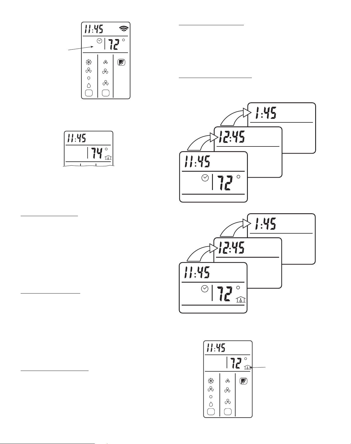
ROOM AIR TEMPERATURE DISPLA Y — The current room
air temperature is automatically displayed when the remote
controller is powered off. To display the room air temperature
when the unit is powered on:
1. Slide down front cover of controller below ON/OFF
button. See Fig. 4.
2. Press the ROOM button. The current room air temperature will be displayed for several seconds, then disappear.
See Fig. 10.
STOP
1
STOP
2
START
3
STOP
START
1
START
2
I
I
I
I
I
I
I
I
I
I
I
I
I
I
I
MODE FAN SWEEP
A
A
START
STOP
1 2 3 SLEEP
DAILY
TIMER
INDICATOR
Fig. 6 — Timer Display Set Up on Remote
Fig. 7 — Set Timer Indicator on
Remote Control Display
I
I
I
I
I
I
I
I
I
I
I
I
I
I
I
MODE FAN SWEEP
A
A
START
STOP
1 2 3 SLEEP
DAILY
SLEEP
TIMER
INDICATOR
Fig. 8 — Sleep Timer Indicator on
Remote Control Display
6
DELAYED START/STOP — This function will delay the
Start/Stop function in increments of 1 hour. Delayed Start/Stop
can be programmed with the unit turned ON or OFF.
With the unit turned ON:
1. Slide down front cover of controller below ON/OFF
button. See Fig. 4.
2. Press the DELAY button. The clock will advance 1 hour
and the word “STOP” and number “3” will flash. See
Fig. 11.
3. Press the DELA Y button once to advance the clock an additional hour until desired delayed time is reached. Be
sure to point the remote control toward the unit while
pressing the DELAY button.
4. The word “STOP” will stop flashing when the command
has been transmitted and received by the unit.
With the unit turned OFF:
1. Slide down front cover of controller below ON/OFF
button. See Fig. 4.
2. Press the DELAY button. The clock will advance 1 hour
and the word “START” and number “3” will flash. See
Fig. 11.
3. Press the DELA Y button once to advance the clock an additional hour until desired delayed time is reached. Be
sure to point the remote control toward the unit while
pressing the DELAY button.
4. The word “START” will stop flashing when the command has been transmitted and received by the unit.
Canceling Delayed Start/Stop
— T o cancel the Delayed S tart/
Stop function, follow the instructions in Canceling Specific
Start/Stop T ime Period section.
NOTE: The Delay setting is stored in Time period 3.
LOCAL SENSE FUNCTION (2-Way Remote Control) —
The local sense function allows the remote control to operate
by transmitting the room air temperature to the unit at regular
intervals from wherever the controller is located in the room.
The unit will then operate to make the air near the remote control reach the desired temperature.
To set Local Sense function:
1. Slide down front cover of controller below ON/OFF
button. See Fig. 4.
2. Press the SENSE button. The “House” symbol will appear on the display screen. See Fig. 12.
3. Place the remote control in desired location in room. Be
sure there is a direct line between the remote control and
the unit.
To Cancel Local Sense function
— While in “Loca l Se nse”
func tio n, press the SENSE button. The “House” symbol will
disappear from the display screen and Local Sense function
will be canceled.
I
I
I
I
I
I
I
I
I
I
I
I
I
I
I
MODE FAN SWEEP
A
A
START
STOP
1 2 3
DAILY
DAILY
TIMER
INDICATOR
Fig. 9 — Daily Timer Indicator on
Remote Control Display
Fig. 10 — Room Air Temperature Indicator on
Remote Control Display
STOP
DAILY
3
START
3
DAILY
I
I
I
I
I
I
I
I
I
I
I
I
I
I
I
MODE FAN SWEEP
A
A
LOCAL
SENSE
INDICATOR
Fig. 11 — Delayed Start/Stop Indicators on
Remote Control Display
Fig. 12 — Local Sense Indicator on Remote
Control Display
PROGRAMMING DISPLAY WITH UNIT ON
PROGRAMMING DISPLAY WITH UNIT OFF
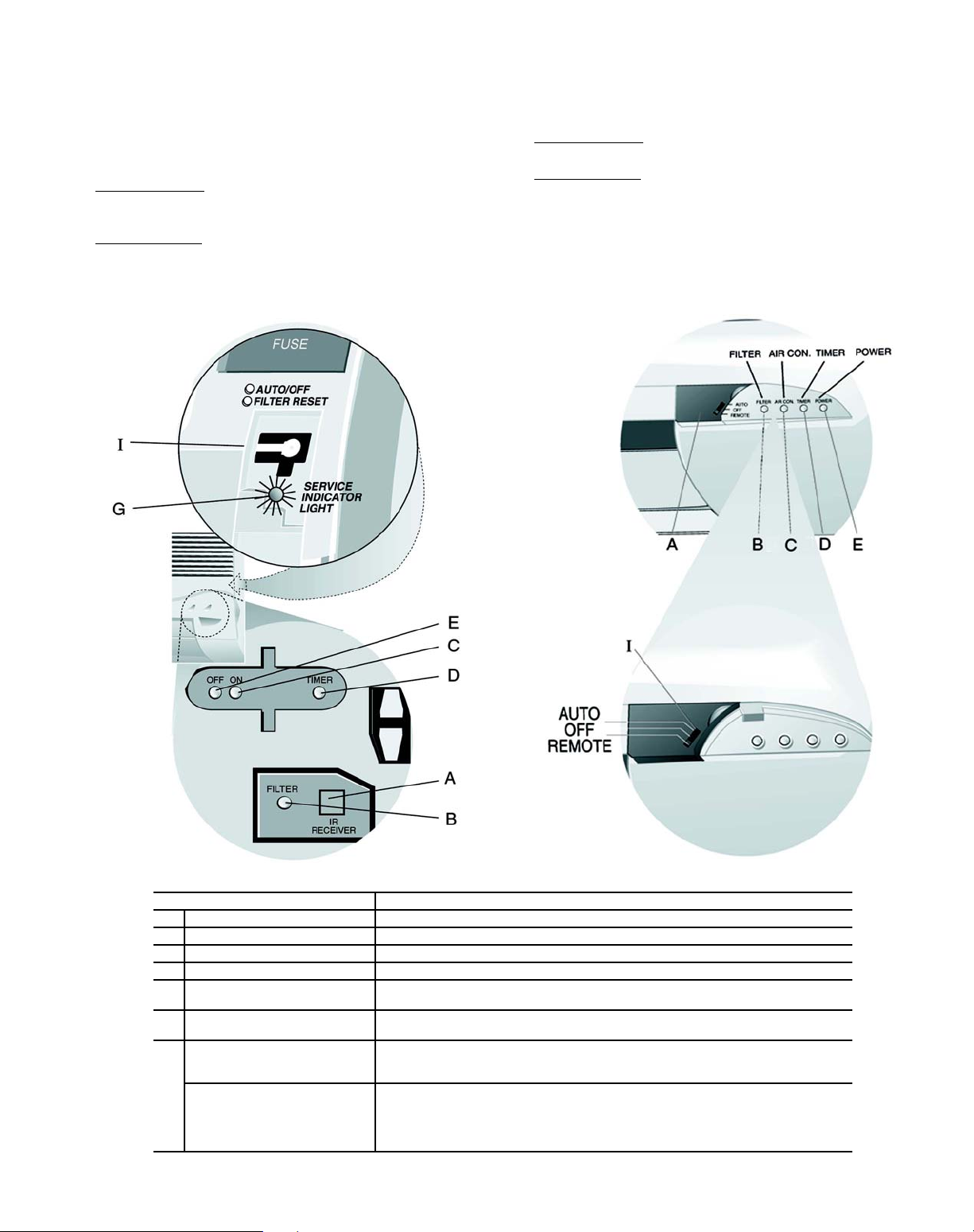
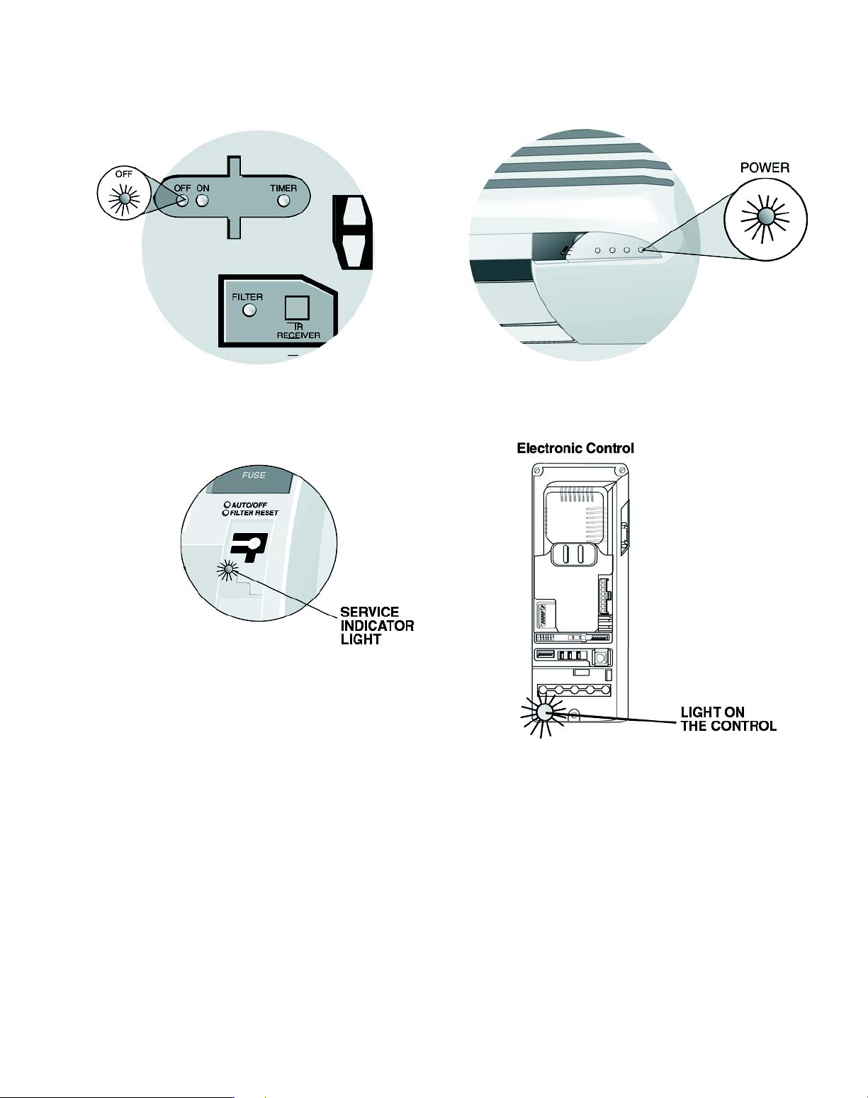
Unit Operation (Fig. 13) — In the event that the remote
control is not working or has been misplaced, the unit will
operate as follows:
40BN018,024,030 — Units always operate by the remote
control. If you lose or break the remote, the unit will continue
to operate but settings cannot be changed until you get a new
remote control.
To Turn Unit Off
under the front cover. See Item I, Fig. 13. The AUTO/OFF
indicator light will go off.
To Turn Unit On
the front cover. See Item I, Fig. 13. The AUTO/OFF indicator
— Push the Operation Push Button located
— Push the Auto/Off button located under
light will light. The unit will operate at the settings that have
been programmed using the remote control.
40BN036 — Unit will operate according to predetermined
factory settings.
To Turn Unit Off
— Slide the Operation Switch on the unit
(Item I, Fig. 13) to the OFF position.
To Turn Unit On
— Slide the Operation Switch on the unit
(Item I, Fig. 13) to the AUTO position. The unit will operate at
a temperature setting of 74 F and will automatically select the
required operation mode and fan speed to maintain this setting.
40BN018,024,030
40BN036
FEATURE DESCRIPTION
A Infrared Receiver Receives transmissions from the remote controller.
B FILTER Indicator Light Lights when the air filters require cleaning.
C (ON)/(AIR COND Indicator Light Lights when the air conditioner operates. Flashes when defrosting.
D TIMER Indicator Light Lights when a TIMER Start or Stop time is set.
POWER Indicator Light Lights when the air conditioner is connected to the electricity supply of the proper
E
SERVICE Indicator Light Lights or flashes accordingly to the malfunction. (See further information on
G
Operation Push Button
(40BN018,024,030)
Operation Slide Switch
I
(40BN036)
line voltage.
page 11).
• Turns the air conditioner ON (Auto) Mode and OFF without Remote Control.
• Resets unit after malfunctions and resets the Filter indicator light. (Press the button continuously for 5 seconds.)
• Turns the air conditioner ON (Auto) Mode and OFF without Remote Control.
• Resets unit after malfunctions and resets the Filter indicator light. (Slide Operation
Switch to OFF position for 5 seconds and then return the switch to remote.)
• Operates the air conditioner using the remote controller when the operation switch
is in REMOTE position.
Fig. 13 — Indoor Unit Display Panel Features
7
8
CLEANING AND MAINTENANCE
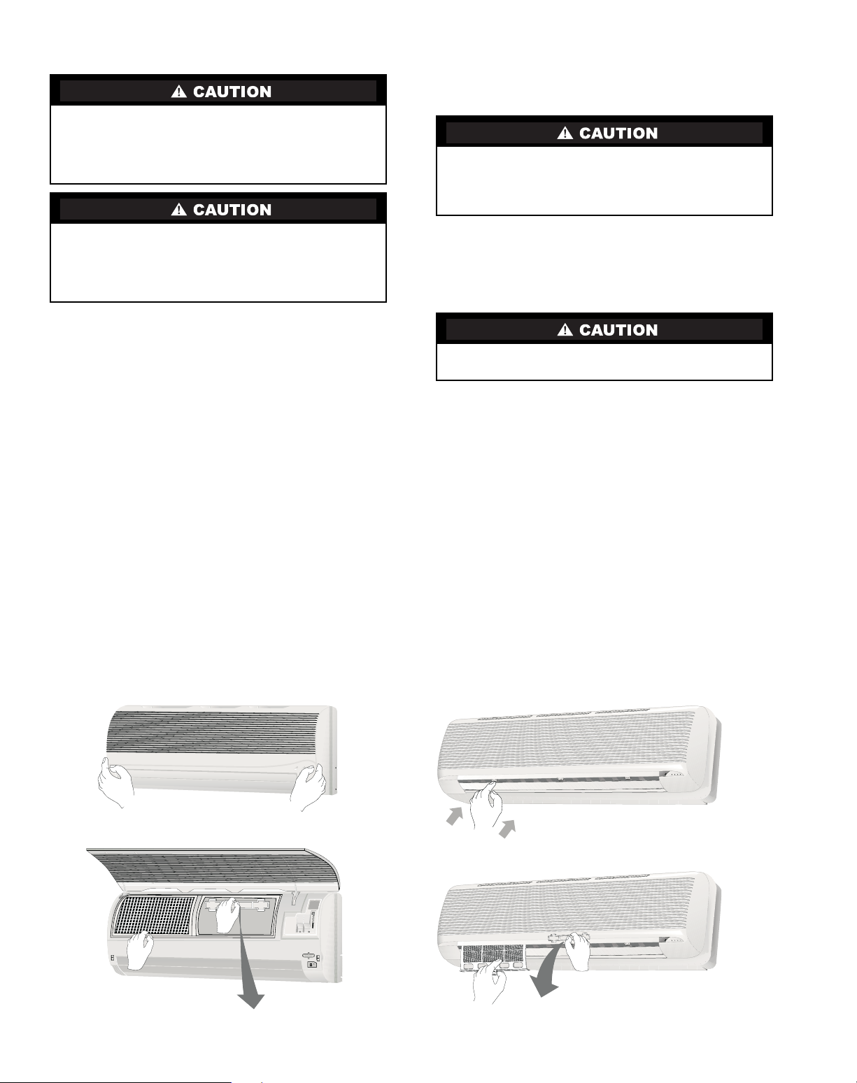
Air Filters —
Remove and clean the air filters when the
Filter indicator light on the unit display panel is lit. See Fig. 13
and 14.
NOTE: If air filters show signs of excessive wear or are torn,
they must be replaced. Contact your local dealer for replacement filters.
1. Open front panel on unit.
2. Pull filters down to remove. (See Fig. 14.)
3. Vacuum filters.
4. Clean with warm water.
5. Shake filter to remove excess water and dry thoroughly.
6. Replace filter by sliding filter behind front grille until filter snaps in place.
7. Slide Operation Switch on unit to OFF position to reset
Filter status indicator light on 40BN036 units, or press the
ON/OFF button for 5 seconds on 40BN018,024 and 036
units.
8. Slide Operation Switch on unit to REMOTE position to
resume remote control operation.
Indoor Unit (40BN) Front Panel — To clean the
front panel on the indoor unit, wipe the outside with a soft, dry
cloth. If necessary, a mild liquid detergent can be applied and
wiped off with a dry cloth.
Indoor Unit (40BN) Coil — To clean the indoor unit
coil, remove the front panel and vacuum the coil fins. Avoid
bending or damaging the fins.
Outdoor Unit (38BN018-036) Coil — To clean the
outdoor unit coil follow the steps below:
1. Remove any dirt, debris or obstruction from discharge
opening.
2. Use a garden hose to spray water on coil. Be sure to spray
between coil fins to remove any debris that may inhibit
heat transfer.
Condensate Drains — Clean all condensate drains at
the start of each cooling season. Check the flow by pouring water into the drain.
To avoid the possibility of electric shock, always turn off
power to the system before performing any cleaning or
maintenance to the system. Turn of f the outdoor disconnect
switch located near outdoor unit. Be sure to disconnect
indoor unit if on a separate switch.
Operating the system with dirty air filters may damage the
indoor unit and could cause reduced cooling performance.
Intermittent system operation, frost build-up on indoor coil
and blown fuses may also result from system operation
with dirty air filters.
When cleaning the front panel, do not use water hotter than
105 F and do not pour water onto the fan coil.
Do not use abrasive or petroleum based cleaners as they
may damage the front panel.
Sharp fins and other metal parts on the outdoor unit coil
can cause personal injury during cleaning.
Fig. 14 — Removing Air Filters
40BN018,024,030 40BN036
System Operation Check List — The items outlined
in the following list will help to assure proper system operation:
• Be sure unit is connected directly to electrical supply.
• Replace both remote control batteries at the same time
when the Low Battery symbol appears.
• Point the remote control toward the unit display panel
when transmitting a command.
• Place the remote control in a location where there is a
direct line for transmission of data to the unit.
• Select a moderate temperature setting. Extreme temperatures waste electricity.
• Keep doors and windows closed while unit is operating.
• Close air vents in unoccupied rooms to save electricity.
• Contact an authorized service representative if a problem
arises that cannot be easily resolved.
• Do not perform cleaning or m aintenance activities while
unit is on.
• Keep remote control out of direct sunlight and heat.
• Keep display panel on unit away from direct sunlight and
heat as this may interfere with remote control transmissions.
• Do not block air intakes and outlets on the indoor or
outdoor units.
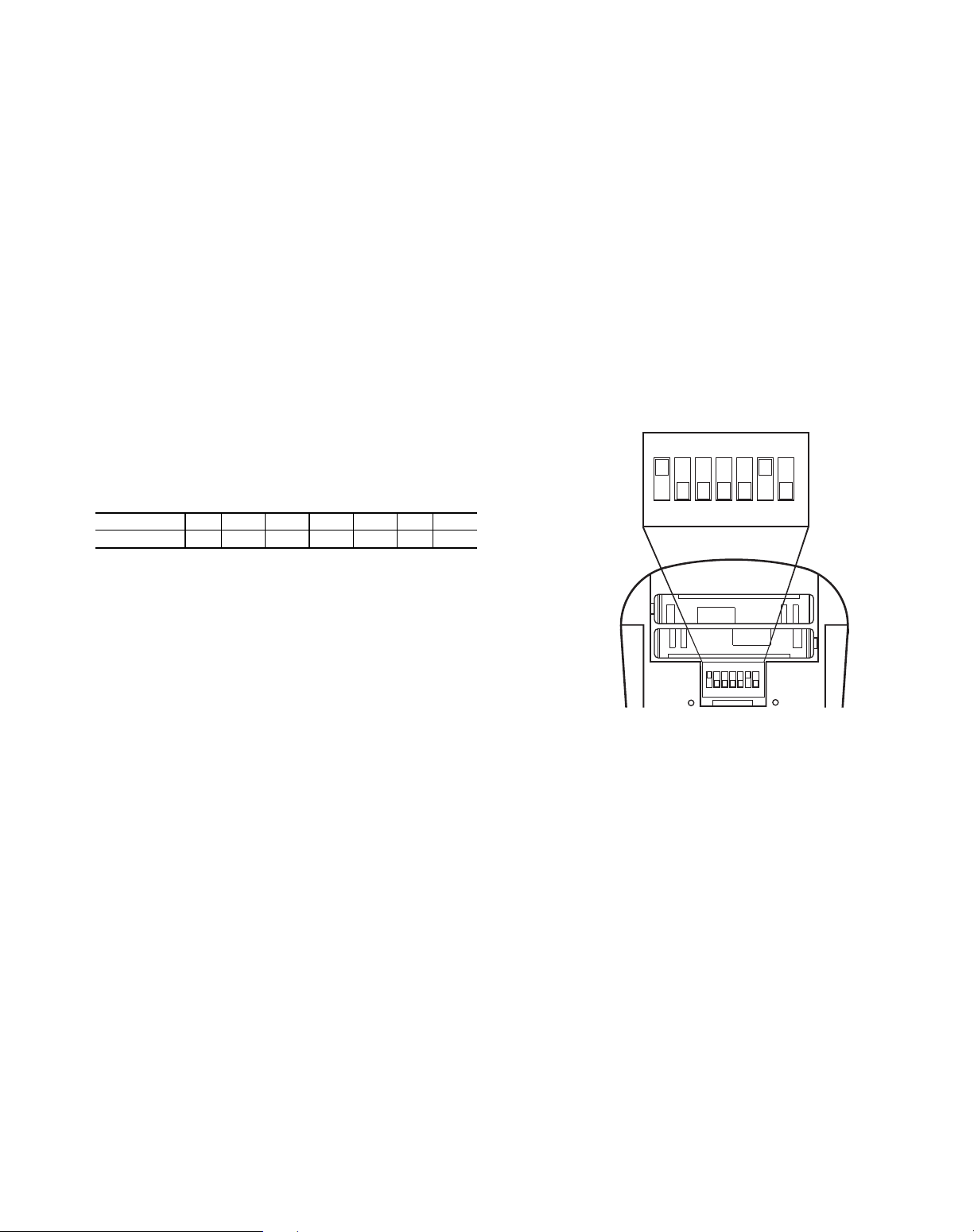
DIP Switch Settings — The remote control contains
seven DIP switches, located in the battery compartment, two of
which control special system characteristics. See Fig. 15. The
DIP switch default positions are set according to the model air
conditioner installed, as per the following table.
SWITCH12 3 4 567
POSITION ON OFF OFF OFF OFF ON OFF
Switch No. 3 should be set as follows:
OFF (default) — When only one air conditioner is installed
in the room.
ON — When there are two air conditioners with remote
controllers installed in the room, in one of the remote controllers this switch must be in the ON position. To activate the new
switch setting, simultaneously press the MODE and ROOM
buttons.
Switch No. 4 should be set as follows:
OFF — Displays temperature in °C, with a 24-hour clock
format.
ON — Displays temperature in °F, with a 12-hour clock
(PM indictor) format.
T o operate the special systems characteristic s:
1. Remove the batteries.
2. Set the DIP switches to the required positions.
3. Wait approximately 2 minutes and return batteries to
proper position.
Energy Saving Recommendations — The follow-
ing recommendations will add greater efficiency to the duct
free system:
• Select a comfortable thermostat setting and leave it at
chosen setting. Avoid continually raising and lowering
the setting.
• Keep unit filter clean. Frequent cleaning may be necessary depending on indoor air quality.
• Use drapes, curtains or shades to keep direct sunlight
from heating room on very hot days.
• Do not obstruct front grille air intake on front panel.
• Turn on air conditioning before indoor air becomes too
uncomfortable.
ON
OFF
1234567
ON
ECE
1234567
Fig. 15 — DIP Switch Location in Remote Control
9
TROUBLESHOOTING GUIDE
Your air conditioner is very reliable and requires little maintenance. However, the air conditioner’s proper operation can be interrupted by a malfunction in the electrical system or by incorrect operation. You can try to overcome these simple malfunctions yourself, with
the aid of the following table and the malfunction displays shown in Fig. 16.
PROBLEM POSSIBLE CAUSE SOLUTION
Air conditioner does not work. • No command is transmitted to air conditioner. • Press the On/Off (Transmission) button.
POWER indicator light is not lit. • Air conditioner is not properly connected. • Check electrical connection.
FILTER indicator light is lit. • Filters require cleaning. • Remove and clean filters.
Air conditioner is working, but
does not perform the required
operation.
(ON)/(AIR COND). Indicator light is
continuously flashing.
Various indicator lights
behave differently than
shown in Fig. 13.
Air conditioner does not operate
with the remote controller.
The remote controller of another
air conditioner interferes with
your air conditioner’s operation.
• Air conditioner did not receive transmitted
command.
• Automatic interrupter switched Off. • Reset interrupter.
• Fuse burned. • Replace fuse.
• Desired temperature setting is higher than
room air temperature when operating in the
COOLING mode.
• Desired temperature setting is lower than room
air temperature when operating in the HEATING
mode.
• The control system is malfunctioning. • For 40BN036 slide the operation switch to OFF
• There is no direct line of sight between
the remote controller and the air conditioner.
• The air conditioner has reached the desired
temperature and stopped the compressor operation (thermostat function).
• Incorrect operation or malfunction. • For 40BN018,024,030 press the operation push
• In 40BN036 the operation push button is in
AUTO or OFF. (For 40BN018,024,030 go to
next bullet.)
• The remote controller batteries are weak. • Replace the batteries.
• The remote controller is malfunctioning. • Turn the air conditioner On and OFF using the
• Both remote controllers are transmitting
on the same wavelength.
• Make sure that remote controller is pointed at air
conditioner during command transmission.
• For 40BN036 move operation switch to OFF
position for 5 sec. and return it to REMOTE.
• For 40BN018,024,030 press the operation push
button continuously for 5 seconds.
• Lower the desired temperature setting.
• Raise the desired temperature setting.
position for 5 sec. and return it to REMOTE.
• For 40BN018,024,030 press the operation push
button, continuously for 5 seconds. Press once
again to operate the air conditioner.
button continuously for 5 seconds.
• For 40BN036 slide the operation slide switch
to OFF position for 5 sec. and return it to
REMOTE.
• Restart the air conditioner, if the problem persists, call service personnel.
• For 40BN036 turn the operating switch to
REMOTE position.
operation push button or slide switch.
• Call service personnel.
10
On each Malfunction, Indicator Light (red) will flash at a constant rate:
40BN018,024 AND 030 40BN036
40BN018,024 AND 03040BN036
Malfunction Indication Display
For 40BN036 the malfunction can be read by the rate of the flashing light on the control. (Raise the front grille list.)
For 40BN018,024,030 the malfunction can be read without raising the front grille by the rate of the flashing service light.
Malfunction Display Light
TH1 Malfunction • 1 short flash
TH2 Malfunction • 2 short flashes
Low Pressure Malfunction • 3 short flashes
High Pressure Malfunction • 4 short flashes
Low Voltage Malfunction • 5 short flashes
High Voltage Malfunction • 6 short flashes
Fig. 16 — Malfunction Displays
11

To save time on a service call, fill out the information listed below:
Dealer’s Name _____________________________________________________________________________________________
Address ___________________________________________________________________________________________________
Telephone _________________________________________ Purchase _____________________________________________
Indoor Model #_____________________________________ Outdoor Model #_______________________________________
Indoor Serial # _____________________________________ Outdoor Serial # _______________________________________
Copyright 2003 Carrier Corporation
Manufacturer reserves the right to discontinue, or change at any time, specifications or designs without notice and without incurring obligations.
Book 1 4
Ta b 3 e 2 f
PC 111 Catalog No. 533-80098 Printed in U.S.A. Form OM38/40-4 Pg 12 4-03 Replaces: New

Le fabricant se réserve le droit d’interrompre ou de changer à tout moment les spécifications ou la conception sans préavis et sans engagement de sa part.
PC 111 Catalogue No. 533-80098 Imprimé aux É.-U. Formulaire OM38/40-4 Pg 13 4-03 Remplace: Nouveau
Livre 1 4
Onglet 3e 2f
MANUEL D’UTILISATION
38BNB,BNE018-036
40BNB,BNE018-036
Systèmes de climatisation et pompe à chaleur sans conduites pour installation murale
TABLE DES MATIÈRES
Page
INTRODUCTION . . . . . . . . . . . . . . . . . . . . . . . . . . . . . 14
GÉNÉRAL. . . . . . . . . . . . . . . . . . . . . . . . . . . . . . . . . .14,15
MODES DE FONCTIONNEMENT . . . . . . . . . . . . . 14
TÉLÉCOMMANDE . . . . . . . . . . . . . . . . . . . . . . . . . . 14
FONCTIONNEMENT . . . . . . . . . . . . . . . . . . . . . . . 15-18
FONCTIONNEMENT DE LA TÉLÉCOMMANDE . 15
FONCTIONNEMENT DE L’APPAREIL . . . . . . . . . 18
NETTOYAGE ET ENTRETIEN . . . . . . . . . . . . . . .20,21
FILTRES À AIR . . . . . . . . . . . . . . . . . . . . . . . . . . . . . 20
Page
FACE AVANT DE L'UNITÉ INTÉRIEURE . . . . . . . 20
SERPENTIN DE L’UNITÉ INTÉRIEURE . . . . . . . . 20
SERPENTIN DE L’UNITÉ EXTÉRIEURE . . . . . . . 20
DRAINS DE CONDENSATION . . . . . . . . . . . . . . . . . 8
LISTE DE VÉRIFICATION
DE FONCTIONNEMENT DU SYSTÈME . . . . . 21
RÉGLAGES DES COMMUTATEURS DIP. . . . . . . . 21
RECOMMANDATIONS D’ÉCONOMIE
D’ÉNERGIE . . . . . . . . . . . . . . . . . . . . . . . . . . . . . 21
GUIDE DE DÉPANNAGE . . . . . . . . . . . . . . . . . . . .22-24
I
I
I
I
MODE AN SWEEP
AA
START
STO
P
1 2 3 SLEEP
DA LY

14
INTRODUCTION
Merci d'avoir opté pour un système sans conduites
Streamline®. Cet appareil a été construit avec le même soin et les
mêmes techniques de conception utilisées pour les équipements de
climatisation de l’Astrodome au Texas, la Chapelle Sixtine à
Rome, la Chambre des députés des États-Unis et des milliers
d’autres installations de par le monde.
Les systèmes sans conduites procurent un confort maximum
avec un minimum de nuisances sonores. En plus de la fonction de
climatisation et/ou de chauffage, ce système sans conduites filtre et
déshumidifie l'air de la pièce pour fournir un confort maximum.
GÉNÉRAL
Ce système sans conduites peut être réglé et mis en
fonctionnement à partir de la télécommande (fournie). Voir Figure
1. Si la télécommande est égarée, le système peut fonctionner à
partir du mode « Auto » de l’appareil.
Modes de fonctionnement — Ce système possède 5
modes de fonctionnement :
• Climatisation (COOLING)
• Ventilation uniquement (FAN ONLY)
• Chauffage (HEATING) (si disponible)
• Déshumidification (DRY)
• Auto (AUTO)
CLIMATISATION — En mode de Climatisation, le système
refroidit, assèche et filtre l’air de la pièce.
VENTILATION UNIQUE MENT — En mode de ventilation
seule, le système filtre et fait circuler l’air de la pièce sans changer
la température de l’air.
CHAUFFAGE — En mode chauffage, le système chauffe et filtre
l’air de la pièce.
DÉSHUMIDIFICATION — En mode déshumidification, le
système assèche, filtre et refroidit légèrement l’air de la pièce. Ce
mode de fonctionnement ne remplace pas à un déshumidificateur.
AUTO — En mode Auto, le système climatise ou chauffe
automatiquement l’air de la pièce en fonction d’un réglage de
température (valeur prédéfinie).
Si la température de la pièce est inférieure à la valeur
prédéfinie, le système fonctionnera en mode chauffage. Si la
température de la pièce est supérieure à la valeur prédéfinie, le
système fonctionnera en mode climatisation.
Télécommande — La télécommande transmet les
commandes de réglage et de fonctionnement au système. La
télécommande possède un écran d’affichage qui indique les
paramètres actuels de fonctionnement du système. La
télécommande peut être fixée sur une surface à l'aide du support de
montage fourni. Voir Figure 1.
IMPORTANT: Les systèmes sans conduites doivent être
installés par du personnel qualifié et autorisé uniquement
et au moyen de matériaux et accessoires approuvés. En
cas de besoin d'assistance technique, d'entretien ou de
réparation, contacter l'installateur ou appeler le 1-800227-7437.
ATTENTION
Manipuler la télécommande avec soin et éviter de la mouiller.
Ceci pourrait l’endommager.
Ne pas laisser la télécommande dans un tiroir ou à proximité
d’un appareil dégageant de la chaleur, car le système essaiera
de refroidir l’air qui environne la télécommande.
IMPORTANT : La télécommande et l’appareil échangent
en permanence des informations relatives à la température
de la pièce. Lors du fonctionnement de la télécommande à
partir du support mural, s’assurer que la télécommande et
l'appareil sont en regard direct. La télécommande peut
piloter l’appareil à une distance de jusqu'à 23 pieds
( 7 mètres) si aucun obstacle n'est présent.
I
I
I
I
M
O
D
E
FA
N
S
W
E
E
P
AA
ST
A
RT
S
TO
P
1 2
3
S
LEE
P
DA
IL
Y
TÉLÉCOMMANDE
SUPPORT DE MONTAGE
MODE
I
I
I
I
I
I
I
I
I
I
I
A
COOLINGs
FAN
HEATING FUNCTION
DRY
AUTO
FAN
A
LOW
MEDIUM
HIGH
AUTO
SWEEP
SWEEP
ON/OFF
HAUT
BAS
BOUTON
DE MODE
BOUTON
HAUT/BAS
BOUTON
MARCHE/ARRÊT
Figure 1 — Système sans conduites
BOUTONS DE LA TÉLÉCOMMANDE —
OPTIONS DE PROGRAMMATION

15
La télécommande peut déclencher les fonctions suivantes :
• Mise en marche et arrêt du système
• Sélection du mode de fonctionnement
• Réglage de la température de la pièce et de la vitesse de
ventilation
• Définition de périodes de temps pour le fonctionnement
automatique
INSTALLATION DES PILES — Deux piles alcalines AAA de
1,5 volt (fournies) sont nécessaires pour le fonctionnement de la
télécommande. Voir la Figure 2 pour l’emplacement des piles.
Pour installer les piles :
1. Enlever le couvercle du compartiment des piles en le faisant
coulisser.
2. Insérer les piles en s’assurant de respecter la polarité
indiquée à l’intérieur du compartiment.
3. Replacer le couvercle du compartiment des piles.
REMARQUE : Remplacer les piles lorsque l’indicateur « Low
battery » (batterie faible) apparaît sur l’écran de la télécommande.
ÉCRA N D’A FFICHA GE — Il existe cinq indicateurs de mode
de fonctionnement qui apparaissent sur l’écran de la
télécommande. Voir Figure 3.
FONCTIONNEMENT
Fonctionnement de la télécommande — La
télécommande possède 3 boutons (voir Figure 4) qui sont utilisés
pour le fonctionnement et le contrôle du système :
• Bouton MODE — change le mode de fonctionnement
• Bouton UP/DOWN (haut/bas) — sélectionne le mode de
fonctionnement désiré
• Bou ton ON/OFF — (marche/arrêt) me t en marche ou arrête
le système et transmet les sélections de programmation à
l’appareil.
REMARQUE : Lors de la transmission d’une commande à partir
de la télécommande vers l’appareil, s’assurer de pointer la
télécommande en direction du côté droit de l’appareil. Voir Figure
4. L’appareil confirmera la réception de la commande en émettant
deux bips audibles.
VITESSE DE VENTILATION — Suivre les étapes ci-dessous
pour sélectionner le mode et la vitesse de ventilation :
1. Appuyer sur le bouton MODE pour sélectionner le mode
Fan (ventilation).
2. Appuyer sur les flèches UP/DOWN (haut/bas) pour
sélectionner la vitesse de ventilation appropriée ou le mode
Auto.
3. Appuyer sur le bouton ON/OFF (marche/arrêt) pour envoyer
les changements vers l'appareil.
REMARQUE : Si l’appareil fonctionne en mode de
DÉSHUMIDIFICATION, la ventilation ne fonctionnera qu’à
basse vitesse et la vitesse ne peut être changée.
RÉGLAGES DE TEMPÉRATURE — Les réglages de
température peuvent être facilement modifiés en pointant la
télécommande vers l'appareil et en appuyant sur le bouton UP/
DOWN (haut/bas) jusqu'à ce que la température désirée apparaisse
sur l'écran. Le symbole apparaît à chaque fois que l’on appuie
sur le bouton UP/DOWN (haut/bas).
Il est également possible de changer la température comme
suit :
1. Sélectionner l’affichage de température en appuyant sur le
bouton MODE. Le symbole de degrés situé à côté des
chiffres se met à clignoter .
2. Appuyer sur le bouton UP/DOWN (haut/bas) pour
sélectionner la température désirée. L’étendue de
température disponible est de 54 F à 90 F.
3. Appuyer sur le bouton ON/OFF (marche/arrêt) pour envoyer
les changements vers l'appareil.
DIRECTION DE L’AIR — Effectuer les étapes suivantes pour
modifier la direction de l’air sortant de l’appareil :
1. Appuyer sur le bouton MODE pour sélectionner la fonction
Sweep (balayage).
2.
Appuyer sur le
haut
du bouton UP/DOWN (haut/bas) pour
déplacer le déflecteur d’air de l’appareil de haut en bas. Le
symbole de circulation d’air indique un déplacement.
3. Appuyer sur le bas du bouton UP/DOWN (haut/bas). Le
déflecteur s’arrête sur l’angle actuel. Le symbole de
circulation d’air reste en position fixe.
4. Appuyer sur le bouton ON/OFF (marche/arrêt) pour envoyer
les changements vers l'appareil.
REMARQUE : Si l’on choisit de placer le déflecteur d'air dans
une position fixe, le déflecteur s'arrête à l'angle dans lequel il se
trouvait lors de la pression sur le bouton ON/OFF (marche/arrêt).
RÉGLAGE DE L'HORLOGE
1. Faire coulisser le couvercle frontal de la télécommande sous
le bouton ON/OFF (marche/arrêt). Voir Figure 4.
2. Appuyer sur le bouton CLOCK (horloge) à l’aide de la
pointe d’un stylo ou d’un trombone. Voir Figure 5.
3. Appuyer sur le bouton UP/DOWN (haut/bas) pour régler les
minutes.
4. Appuyer sur le bouton MODE. Les chiffres des heures
clignotent.
5. Appuyer sur le bouton UP/DOWN (haut/bas) pour régler les
heures.
6. Pour confirmer le réglage actuel de l’horloge, appuyer de
nouveau sur le bouton CLOCK (horloge) à l’aide de la
pointe d’un stylo ou d’un trombone. La télécommande
retournera automatiquement à l’écran précédent et affichera
l’horloge.
IMPORTANT : Si aucun changement n’intervient pendant
10 secondes, la télécommande retournera au réglage précédent.
ARRIÈRE DE
LA TÉLÉCOMMANDE
2 PILES AAA 1,5 V
COUVERCLE DU
COMPARTIMENT DES PILES
A
CLIMATISATION
CHAUFFAGE
VENTILATION
UNIQUEMENT
DÉSHUMIDIFICATION
AUTO
I
I
I
I
I
I
I
I
I
I
I
I
I
I
I
I
I
Figure 2 — Emplacement des piles de la
télécommande
Figure 3 — Indicateurs du mode de fonctionnement
sur la télécommande

16
PROGRAMMATION DES PÉRIODES DE TEMPS — Le
système sans conduites peut être programmé pour fonctionner à
des niveaux désirés. S’assurer de régler l’horloge avant de
programmer le système.
• Les incréments de temps sont des intervalles de 10 minutes.
• Le témoin indicateur de marche/arrêt d’horloge de
l’appareil s’allume lorsqu’une de période de temps est
programmée. Voir Figure 4.
• L’écran de la télécommande affiche l’heure de Marche/
Arrêt de la période de temps qui est la plus proche de
l’heure actuelle. Si l’appareil est sur ON (marche),
« STOP » (arrêt) et la période de temps sont affichés. Si
l’appareil est sur OFF (arrêt), « START » (marche) et la
période de temps sont affichés.
Réglage de l’heure de Marche/Arrêt — La fonction de
minuterie est utilisée pour définir les heures de marche/arrêt Trois
périodes de temps différentes pouvant être séparées d’un
maximum de dix heures et situées dans une tranche de 24 heures
peuvent être programmées à l’aide de cette fonction.
IMPORTANT : Veiller à bien pointer la télécommande en
direction de l’unité lorsque l’on appuie sur les boutons
TIMER (minuterie) ou SET (réglage).
CAPTEUR DE TEMPÉRATURE
INDICATEUR DE TRANSMISSION
BAS INDICATEUR DE BATTERIE
BOUTON HAUT/BAS
TEMPÉRATURE DÉSIRÉE
INDICATEUR D'ACTIVITÉ DE CAPTEUR
INDICATEUR DE BALAYAGE
BOUTON ON/OFF
BOUTON " CLOCK " (HORLOGE)*
BOUTON DE TEMPÉRATURE DE LA PIÈCE*
BOUTON " DELAY " (DÉLAI)
BOUTON DE DÉTECTION LOCALE*
OUVERTURE DE TRANSMISSION DE SIGNAL INFRAROUGE
HORLOGE
INDICATEURS DE DÉBUT/FIN
DE MINUTERIE JOURNALIÈRE
BOUTON DE MODE
INDICATEURS DE MODE
DE FONCTIONNEMENT CLIMATISATION, VENTILATION,
CHAUFFAGE, DÉSHUMIDIFICATION,
AUTO
INDICATEURS DE VENTILATION FAIBLE, MOYEN, FORT, AUTO
BOUTONS DE RÉGLAGE
DE MINUTERIE*
PANNEAU COULISSANT
I
I
I
I
I
I
I
I
I
I
I
MODE
FAN
SWEEP
AA
START
STOP
1 2 3 SLEEP
DAILY
TIMER
SET
CLEAR
DELAY
SENSE
ROOM
CLOCK
Figure 4 — Télécommande
*Boutons situés sous le couvercle à coulisse supérieur.
I
I
I
I
I
I
I
I
I
MODE FAN SWEEP
AA
START
STOP
1 2 3 SLEEP
DAILY
TIMER
SET
CLEAR
DELAY
SENSE
ROOM
CLOCK
Figure 5 — Emplacement du bouton de réglage
de l’horloge sur la télécommande

17
1. Faire coulisser le couvercle frontal de la télécommande sous
le bouton ON/OFF (marche/arrêt). Voir Figure 4.
2. Appuyer sur le bouton TIMER (minuterie). À chaque
pression sur le bouton, l'heure de marche ou d'arrêt suivante
s'affiche sur l'écran. Voir Figures 6 et 7.
3. Appuyer sur le bouton UP/D OWN (haut/bas) pour régler
l’heure.
4. Pour définir une autre période de temps, appuyer sur le
bouton TIMER (minuterie) pour aller à une autre période de
temps et répéter les étapes 2 et 3 ci-dessus.
5. Appuyer sur le bouton SET (réglage) pour valider l'heure
affichée une fois l'opération terminée. Voir Figure 4.
REMARQUE : Si aucun changement n’intervient pendant 10
secondes, la télécommande retournera à l’affichage précédent.
Pour corriger une erreur, les réglages de minuterie programmés
doivent être annulés et ré-entrés. Voir le paragraphe Annulation de
la minuterie de jour.
Minuterie de nuit —
La fonction de minuterie de nuit permet de
définir la température désirée durant la période de sommeil de
l'occupant de la pièce. La température de l’air de la pièce augmente
graduellement jusqu'à ce que la période de temps soit terminée.
L’appareil retourne ensuite au réglage de température précédent.
Effectuer les étapes suivantes pour définir la minuterie de nuit :
1. Faire coulisser le couvercle frontal de la télécommande sous
le bouton ON/OFF (marche/arrêt). Voir Figure 4.
2. Appuyer sur le bouton TIMER (minuterie) jusqu'à ce que la
fonction Sleep (sommeil) apparaisse.
3. Sélectionner la période de temps « SLEEP » (sommeil). V oir
Figure 8.
4. Appuyer sur le bouton UP/D OWN (haut/bas) pour définir
l’heure de début et appuyer sur le bouton TIMER
(minuterie) pour définir l’heure de fin.
5. Appuyer sur le bouton SET (réglage) pour valider l'heure
affichée une fois l'opération terminée. Voir Figure 4.
Réglage de la minuterie de jour — Les périodes de temps
peuvent être programmées pour faire fonctionner le système à des
moments donnés durant une période de 24 heures. Cette fonction
de minuterie peut être utilisée pour les 3 périodes de temps et la
période de sommeil décrite ci-dessus.
REMARQUE : La minuterie de jour ne fonctionne que lorsqu’il
existe un vis-à-vis direct entre la télécommande et l’appareil.
1. Faire coulisser le couvercle frontal de la télécommande sous
le bouton ON/OFF (marche/arrêt). Voir Figure 4.
2. Appuyer sur le bouton TIMER (minuterie) pour sélectionner
la période de temps qui sera activée journellement.
3. Appuyer sur le bouton SET (réglage) et le maintenir enfoncé
jusqu'a ce que le mot « DAILY » (journellement) apparaisse
sur l’écran. Voir Figure 9.
4. Appuyer de nouveau sur le bouton SET (réglage) pour
confirmer le fonctionnement journalier de la période de
temps sélectionnée. S’assurer de pointer la télécommande
en direction de l’appareil lorsque l’on appuie sur le bouton
SET (réglage).
Annulation de la minuterie de jour — Cette fonction annulera
le programme de minuterie de jour sélectionné.
1. Faire coulisser le couvercle frontal de la télécommande sous
le bouton ON/OFF (marche/arrêt). Voir Figure 4.
2. Appuyer sur le bouton TIMER (minuterie) pour sélectionner
la période de temps qui sera activée journellement.
3. Appuyer sur le bouton SET (réglage) et le maintenir enfoncé
jusqu'a ce que le mot « DAILY » (journellement)
disparaisse de l’écran.
4. Appuyer de nouveau sur le bouton SET (réglage) pour
désactiver le fonctionnement journalier de la période de
temps sélectionnée. S’assurer de pointer la télécommande
en direction de l’appareil lorsque l’on appuie sur le bouton
SET (réglage).
Annulation d'une heure de début ou de fin d'une période de
temps spécifique — Il est possible d’annuler une ou plusieurs
minuteries en effectuant les étapes suivantes :
1.Faire coulisser
le couvercle frontal de la télécommande sous le bouton ON/
OFF (marche/arrêt). Voir Figure 4.
2. Appuyer sur le bouton TIMER (minuterie) et sélectionner la
minuterie que l’on veut annuler (1,2,3, ou Sleep (sommeil))
3. Appuyer sur le bouton CLEAR (effacer) pour annuler la
période de temps sélectionnée. Les heures de début et de fin
disparaîtront de l’écran.
4. Appuyer sur le bouton SET (réglage) pour confirmer
l’annulation. S’assurer de pointer la télécommande en
direction de l’appareil lorsque l’on appuie sur le bouton SET
(réglage).
Annulation de toutes les périodes de temps— Il est possible
d’annuler toutes les minuteries en effectuant les étapes suivantes:
1. Faire coulisser le couvercle frontal de la télécommande sous
le bouton ON/OFF (marche/arrêt). Voir Figure 4.
2. Appuyer sur le bouton TIMER (minuterie).
3. Appuyer sur le bouton CLEAR (effacer) et le maintenir
enfoncé jusqu'à ce que toutes les heures de début et de fin
disparaissent de l’écran.
4. S’assurer que le témoin de minuterie est éteint sur l’appareil.
5. Appuyer sur le bouton SET (réglage) pour confirmer
l’annulation. S’assurer de pointer la télécommande en
direction de l’appareil lorsque l’on appuie sur le bouton SET
(réglage).
AFFICHAGE DE LA TEMPÉRATURE DE L’AIR DE LA
PIÈCE — La température actuelle de l’air de la pièce est
automatiquement affichée lorsque la télécommande est mise hors
tension. Pour afficher la température de l’air de la pièce lorsque
l’appareil est mis sous tension :
1. Faire coulisser le couvercle frontal de la télécommande sous
le bouton ON/OFF (marche/arrêt). Voir Figure 4.
STOP
1
STOP
2
START
3
STOP
START
1
START
2
I
I
I
I
I
I
I
I
I
I
I
I
I
I
MODE FAN SWEEP
A
A
START
STOP
1 2 3 SLEEP
DAILY
INDICATEUR
DE MINUTERIE
Figure 6 — Affichage du réglage de la minuterie
sur l’écran de la télécommande
Figure 7 — Indicateur de réglage de la minuterie
sur l’écran de la télécommande
I
I
I
I
I
I
I
I
I
I
I
I
I
I
I
MODE FAN SWEEP
A
A
START
STOP
1 2 SLEEP
DAILY
INDICATEUR
DE MINUTERIE
DE NUIT
Figure 8 — Indicateur de minuterie de mise en veille
sur l’écran de la télécommande

18
2. Appuyer sur le bouton ROOM (pièce). La température
actuelle de l’air de la pièce sera affichée pendant plusieurs
secondes puis disparaîtra. Voir Figure 10.
DÉCALAGE DÉBUT/FIN — Cette fonction décale la fonction
début/fin par incréments de 1 heure. Le décalage de début/fin peut
être programmé avec l’appareil en position ON (marche) ou OFF
(arrêt).
Avec l’appareil en position ON (marche) :
1. Faire coulisser le couvercle frontal de la télécommande sous
le bouton ON/OFF (marche/arrêt). Voir Figure 4.
2. Appuyer sur le bouton DELAY (décalage). L’horloge
avancera d’une heure et le mot « STOP » (arrêt) et le chiffre
3 clignoteront. Voir Figure 11.
3. Appuyer sur le bouton DELAY (décalage) une fois pour
faire avancer l’horloge d’une heure supplémentaire jusqu'à
ce que le décalage désiré soit atteint. S’assurer de pointer la
télécommande en direction de l’appareil lorsque l’on appuie
sur le bouton DELA Y (d écalage).
4. Le mot « STOP » (arrêt) cessera de clignoter une fois que la
commande aura été transmise et reçue par l'appareil.
Avec l’appareil en position OFF (arrêt) :
1. Faire coulisser le couvercle frontal de la télécommande sous
le bouton ON/OFF (marche/arrêt). Voir Figure 4.
2. Appuyer sur le bouton DELAY (décalage). L’horloge
avancera d’une heure et le mot « START » (marche) et le
chiffre 3 clignoteront. Voir Figure 11.
3. Appuyer sur le bouton DELAY (décalage) une fois pour
faire avancer l’horloge d’une heure supplémentaire jusqu'à
ce que le décalage désiré soit atteint. S’assurer de pointer la
télécommande en direction de l’appareil lorsque l’on appuie
sur le bouton DELA Y (d écalage).
4. Le mot « START » (marche) cessera de clignoter une fois
que la commande aura été transmise et reçue par l'appareil.
Annulation de début/fin décalé — Pour annuler la fonction de
décalage de début/fin, suivre les instructions du paragraphe
Annulation d’une heure de début ou de fin d’une période de temps
spécifique.
REMARQUE : Le réglage de délai est enregistré dans la période
de temps 3.
FONCTION DE DÉTECTION LOCALE (télécommande
bidirectionnelle) — La fonction de détection locale permet à la
télécommande de fonctionner en transmettant la température de
l’air de la pièce à l’appareil à des intervalles réguliers, à partir de
l’endroit où la télécommande se trouve dans la pièce. L’appareil
fonctionnera de manière à ce que l'air situé à proximité de la
télécommande atteigne la température désirée.
Pour régler la fonction de détection locale :
1. Faire coulisser le couvercle frontal de la télécommande sous
le bouton ON/OFF (marche/arrêt). Voir Figure 4.
2. Appuyer sur le bouton SENSE (détection). L'icône
« House » (maison) apparaît sur l'écran. Voir Figure 12.
3. Placer la télécommande à l’emplacement désiré dans la
pièce. S’assurer qu’il existe un vis-à-vis direct entre la
télécommande et l’appareil.
Pour annuler la fonction de détection locale : — Lorsque la
télécommande est dans la fonction « Local Sense » (détection
loca le), appuyer sur le bouton SENSE (détection). Le symbole
I
I
I
I
I
I
I
I
I
I
I
I
I
I
I
MODE FAN SWEEP
A
A
START
STOP
1 2 3
DAILY
INDICATEUR
DE MINUTERIE
DE JOUR
Figure 9 — Indicateur de minuterie de jour
sur l’écran de la télécommande
Figure 10 — Indicateur de température de la pièce
sur l’écran de la télécommande
STOP
DAILY
3
START
3
DAILY
I
I
I
I
I
I
I
I
I
I
I
I
I
I
I
MODE FAN SWEEP
A
A
INDICATEUR
DE DÉTECTION
LOCALE
Figure 11 — Indicateurs de décalage de début/fin sur
l’écran de la télécommande
Figure 12 — Indicateur détection locale sur l’écran de
la télécommande
ÉCRAN DE PROGRAMMATION AVEC APPAREIL
EN MARCHE
ÉCRAN DE PROGRAMMATION AVEC APPAREIL
À L’ARRÊT

« House » (maison) disparaît de l'écran et la fonction de détection
locale est annulée.
Fonction de l’appareil (Figure 13) — Dans le cas où la
télécommande ne fonctionne pas ou qu’elle a été égarée, l’appareil
fonctionne de la manière suivante :
40BN018,024,030 — Appareil toujours contrôlé par la
télécommande. Si vous perdez ou endommagez la télécommande,
l’appareil continuera de fonctionner mais il sera impossible de
changer les réglages jusqu'à ce que vous obteniez une
télécommande neuve.
Pour arrêter l’appareil — Appuyer sur le bouton poussoir situé
sous le couvercle frontal. Voir élément I, Figure 13. Le témoin
lumineux AUTO/OFF (auto/arrêt) s’éteindra.
Pour allumer l’appareil — Appuyer sur le bouton Auto/Off
(auto/arrêt) situé sous le couvercle frontal. Voir élément I, Figure
13. Le témoin lumineux AUTO/OFF (auto/arrêt) s’allumera.
L’appareil fonctionnera en fonction des réglages qui ont été
programmés à l’aide de la télécommande.
40BN036 — L’appareil fonctionnera en fonction des réglages
d’usine.
Pour arrêter l’appareil — Placer le commutateur de
fonctionnement de l’appareil (élément I, Figure 13) sur la position
OFF (arrêt).
Pour allumer l’appareil — Placer le commutateur de
fonctionnement de l’appareil (élément I, Figure 13) sur la position
AUTO. L’appareil fonctionnera à un réglage de température de
40BN018,024,030
40BN036
FONCTION DESCRIPTION
A Récepteur infrarouge Reçoit les transmissions de la télécommande.
B Témoin lumineux FILTER (filtre) S’allume lorsque le filtre à air doit être nettoyé.
Témoin lumineux (ON)/(AIR COND)
C
(marche/climatisation)
D Témoin lumineux TIMER (minuterie) S’allume lorsque l'heure de début ou de fin de minuterie est défini.
E Indicateur lumineux d'alimentation S’allume lorsque le climatiseur est branché sur une prise électrique du voltage approprié.
Témoin lumineux SERVICE
G
(entretien)
Bouton poussoir de mise en marche
(40BN018,024,030)
Commutateur de fonctionnement
I
(40BN036)
S’allume lorsque le climatiseur fonctionne. Clignote lors du dégivrage.
S’allume ou clignote en fonction du problème. (Voir informations complémentaires à la
page 23)
• Mise en marche (mode auto) et arrêt du climatiseur sans télécommande.
• Réinitialise l’appareil après un problème de fonctionnement et réinitialise le témoin de
filtre. (Appuyer sur le bouton pendant 5 secondes).
• Mise en marche (mode auto) et arrêt du climatiseur sans télécommande.
• Réinitialise l’appareil après un problème de fonctionnement et réinitialise le témoin de
filtre. (Placer le commutateur sur la position OFF (arrêt) pendant 5 secondes puis ramener
en position « remote » (télécommande)).
• Fait fonctionner le climatiseur à l’aide de la télécommande lorsque le commutateur est en
position REMOTE (télécommande).
Figure 13 — Caractéristiques de la face avant de l’appareil intérieur
19

20
74F et sélectionnera automatiquement le mode de fonctionnement
et la vitesse de soufflerie nécessaire pour maintenir cette
température.
NETTOYAGE ET ENTRETIEN
Filtres à air — Enlever et nettoyer les filtres à air lorsque le
témoin de filtre à air est allumé sur la face avant de l'unité
intérieure. Voir Figures 13 et 14.
REMARQUE : Si les filtres à air montrent des signes d’une usure
excessive ou sont déchirés, ils doivent être remplacés. Contacter
votre revendeur local pour obtenir des filtres de rechange.
1. Ouvrir le couvercle avant de l’unité intérieure.
2. Tirer les filtres vers le bas pour les extraire. (Voir la
Figure 14)
3. Aspirer les filtres.
4. Nettoyer dans de l’eau chaude.
5. Secouer le filtre pour enlever l’excès d’eau et faire sécher
complètement.
6. Replacer le filtre en l’insérant derrière la grille frontale
jusqu'à ce que le filtre s’enclenche en place.
7. Placer le commutateur de fonctionnement sur la position
OFF (arrêt) pour réinitialiser le témoin lumineux de filtre sur
les appareils 40BN036, ou appuyer sur le bouton ON/OFF
(marche/arrêt) pendant 5 secondes sur les appareils
40BN018,024 et 036.
8. Placer le commutateur de fonctionnement sur la position
REMOTE (télécommande) pour reprendre le mode de
fonctionnement par télécommande.
Face avant de l’unité intérieure (40BN) — Pour
nettoyer la face avant de l’unité intérieure, essuyer la surface avec
un chiffon doux et sec. Si nécessaire, un détergent liquide de force
moyenne peut être appliqué et essuyé à l’aide d’un chiffon doux et
sec.
Serpentin de l’unité intérieure (40BN) — Pour
nettoyer le serpentin de l’unité intérieure, enlever la face avant et
aspirer les ailettes du serpentin. Éviter de tordre ou d'endommager
les ailettes.
Serpentin de l’unité extérieure (38BN018-036) —
Suivre les étapes suivantes pour nettoyer le serpentin de l’unité
extérieure :
1. Éliminer la terre, poussières, débris et autres obstructions de
l’ouverture de sortie.
2. Utiliser un tuyau d’arrosage de jardin pour asperger le
serpentin. Veiller à bien arroser entre les ailettes du serpentin
pour éliminer les débris qui peuvent empêcher l’échange de
chaleur.
Drains de condensation — Nettoyer tous les drains de
condensation au début de chaque saison chaude. Vérifier que
l’écoulement se fait librement en versant de l’eau dans le drain.
ATTENTION
Afin d’éviter le risque de chocs électriques, toujours couper
l'arrivée de courant électrique au niveau de l'appareil avant de
nettoyer ou d’intervenir sur le système. Arrêter le disjoncteur
situé à proximité de l'unité extérieure. S’assurer de
déconnecter l’unité intérieure si branchée sur un disjoncteur
séparé.
ATTENTION
Faire fonctionner le système avec un filtre à air sale peut
endommager l’unité intérieure et peut réduire les
performances de climatisation. Un fonctionnement
intermittent du système, des agglomérations de givre dans le
serpentin de l’unité extérieure et des fusibles grillés peuvent
également être la conséquence d’un fonctionnement avec un
filtre à air sale.
ATTENTION
Lors du nettoyage de la face avant, ne pas utiliser de l’eau à
une température supérieure à 105F et ne pas introduire de
l’eau dans le ventilateur.
Ne pas utiliser d’abrasif ou de nettoyant à base de pétrole, ceci
pouvant endommager la face avant.
ATTENTION
Les ailettes acérées et autres pièces métalliques du serpentin
de l’unité extérieure peuvent infliger des blessures durant le
nettoyage.
Figure 14 — Dépose des filtres à air
40BN018,024,030 40BN036

Liste de vérification de fonctionnement du
système —
Les éléments décrits dans la liste ci-dessous
aideront à assurer un bon fonctionnement du système :
• S’assurer que l’appareil est directement raccordé à
l’alimentation électrique.
• Remplacer les deux piles de la télécommande en même
temps lorsque l'indicateur de batterie faible apparaît.
• Pointer la télécommande en direction de la face avant de
l'appareil lors de la transmission d'une commande.
• Placer la télécommande dans un emplacement en vis à vis
direct de l’appareil pour une bonne transmission des
données.
• Sélectionner un réglage de température modéré. Les
températures extrêmes gaspillent de l’électricité.
• Laisser les portes et les fenêtres fermées durant le
fonctionnement de l’appareil.
• Fermer les bouches de ventilation dans les pièces
inoccupées pour économiser l’électricité.
• Contacter un réparateu r agréé si un problème qui ne peut
être résolu simplement apparaît.
• Ne pas entreprendre d’opération de nettoyage ou d’entretien
lorsque l’appareil est en fonctionnement.
• Ne pas exposer la télécommande à la lumière directe du
soleil ainsi qu'à d'autres sources de chaleur.
• Ne pas expose r l’écran d’affichage à la lumière directe du
soleil ou à une autre source de chaleur qui pourrait interférer
avec les transmissions de celle-ci.
• Ne pas obstruer les entrées et les sorties d’air de l'unité
intérieure et de l'unité extérieure.
Réglages des commutateurs DIP — La télécommande
contient des commutateurs DIP, situés dans le compartiment des
piles, deux de ces commutateurs contrôlent des caractéristiques
spéciales du système. Voir Figure 15. Les positions par défaut des
commutateurs DIP sont réglées en fonction du modèle du
climatiseur installé, en fonction du tableau suivant.
Le commutateur numéro 4 doit être réglé comme suit :
OFF — Affiche la température en °C avec un format de temps
en cycles de 24 heures.
ON — Affiche la température en °F avec un format de temps
en cycles de 12 heures (indicateur PM).
Pour faire fonctionner les caractéristiques spéciales du
système :
1. Enlever les piles.
2. Régler les commutateurs DIP sur les positions choisies.
3. Attendre environ deux minutes et replacer les piles.
Recommandations d’économie d’énergie. — Les
recommandations suivantes augmenteront le rendement du
système :
• Sélec tionner un réglage de thermostat confortable et garder
ce réglage. Éviter d'augmenter et de diminuer constamment
le réglage.
• S’assurer que le filtre est toujours propre. Des nettoyages
fréquents peuvent être nécessaires en fonction de la qualité
de l’air intérieur.
• Utiliser des draperies, des rideaux ou des stores pour
empêcher les rayons directs du soleil de réchauffer la pièce
durant les journées très chaudes.
• Ne pas obstruer la grille frontale d’admission d’air sur la
face avant de l’appareil.
• Allumer la climatisation avant que la température de l’air
intérieur ne devienne trop inconfortable.
ON
OFF
1234567
COMMUTATEUR12 3 4 567
POSITION ON OFF OFF OFF OFF ON OFF
Le commutateur numéro 3 doit être réglé comme suit :
OFF (défaut) — Lorsque un seul climatiseur est installé dans la
pièce.
ON — Lorsque deux climatiseurs avec télécommandes sont
installés dans la pièce, ce commutateur doit être en position ON
sur l'une des deux télécommandes. Pour activer le nouveau réglage
du commutateur il faut appuyer simultanément sur les boutons
MODE et ROOM.
ON
ECE
1234567
Figure 15 — Emplacement des commutateurs DIP
dans la télécommande.
21

GUIDE DE DÉPANNAGE
Votre climatiseur est très fiable et ne nécessite que peu d’entretien. Ceci dit, le fonctionnement correct du climatiseur peut être interrompu
par un mauvais fonctionnement dans le système électrique ou par une autre cause. Vous pouvez essayer de remédier à ces petits problèmes
vous-même, à l'aide du tableau suivant et des informations données à la Figure 16.
PROBLÈME CAUSE POSSIBLE SOLUTION
Le climatiseur ne fonctionne pas. • Aucune commande n’est transmise au
Le témoin d’alimentation n’est pas
allumé.
Le témoin FILTER (filtre) est allumé. • Les filtres doivent être nettoyés. • Retirer les filtres et les nettoyer.
Le climatiseur fonctionne, mais
refuse d’effectuer l’opération
demandée.
Le témoin lumineux (ON)/(AIR COND)
(marche/climatisation) clignote
en permanence.
Divers témoins lumineux ne
se comportent pas comme
indiqué à la Figure 13.
Le climatiseur ne fonctionne pas
avec la télécommande.
La télécommande d’un autre
climatiseur interfère avec
le fonctionnement de votre climatiseur.
climatiseur.
• Le climatiseur n’a pas reçu la commande
transmise.
• Le climatiseur n’est pas correctement raccordé
à la source de courant électrique.
• Disjoncteur automatique sur Off. • Réinitialiser le disjoncteur.
• Fusible brûlé. • Remplacer le fusible.
• Le réglage de température désirée est
supérieur à la température de l'air de la pièce
lors du fonctionnement en mode COOLING
(climatisation).
• Le réglage de température désirée est inférieur
à la température de l'air de la pièce lors du
fonctionnement en mode HEATING
(chauffage).
• Le système de contrôle ne fonctionne pas
correctement.
• Il n’existe pas de vis à vis direct entre
la télécommande et le climatiseur.
• Le climatiseur a atteint la température désirée
et a stoppé le fonctionnement du compresseur
(fonction thermostat).
• Fonctionnement incorrect ou défaillance. • Pour les modèles 40BN018,024,030 , appuyer
• Pour le modèle 40BN036, le bouton de
fonctionnement est sur AUTO ou OFF. (Pour les
modèles 40BN018,024,030, aller au point
suivant).
• Les piles de la télécommande sont faibles. • Remplacer les piles.
• La télécommande ne fonctionne pas
correctement.
• Les deux télécommande fonctionnent
sur la même longueur d’onde.
• Appuyer sur le bouton On/Off (transmission).
• S’assurer que la télécommande est pointée en
direction du climatiseur durant la transmission
des commandes.
• Vérifier les branchements électriques.
• Pour le modèle 40BN036, déplacer le
commutateur de mise en marche sur la position
OFF (arrêt) pendant 5 secondes et le replacer
sur la position REMOTE (télécommande).
• Pour les modèles 40BN018,024,030 , appuyer
sur le bouton poussoir de mise en marche
pendant 5 secondes.
• Diminuer le réglage de température désirée.
• Augmenter le réglage de température désirée.
• Pour le modèle 40BN036, déplacer le
commutateur de mise en marche sur la position
OFF (arrêt) pendant 5 secondes et le remettre
en position REMOTE (télécommande).
• Pour les modèles 40BN018,024,030 , appuyer
sur le bouton poussoir de mise en marche
pendant 5 secondes. Appuyer de nouveau pour
faire fonctionner le climatiseur.
sur le bouton poussoir de mise en marche
pendant 5 secondes.
• Pour le modèle 40BN036, déplacer le
commutateur de mise en marche sur la position
OFF (arrêt) pendant 5 secondes et le replacer
sur la position REMOTE (télécommande).
• Redémarrer le climatiseur, si le problème
persiste appeler un réparateur.
• Pour le modèle 40BN036 placer le commutateur
de fonctionnement sur la position REMOTE.
• Allumer et éteindre le climatiseur à l'aide du
bouton poussoir ou du commutateur.
• Appeler un réparateur.
22

Pour chaque défaillance, un témoin lumineux (rouge) clignotera à vitesse constante :
40BN018,024 AND 030 40BN036
40BN018,024 AND 03040BN036
Indicateur de défaillance
Pour le 40BN036, la défaillance peut être identifiée par la vitesse de clignotement de l’indicateur lumineux. (Soulever la liste de la grille frontale).
Pour les modèles 40BN018,024,030 la cause de la défaillance peut être lue sans soulever la grille frontale, par la vitesse de clignotement du
témoin d'entretien.
Témoin de défaillance
défaillance TH1 • 1 clignotement bref
défaillance TH2 • 2 clignotements brefs
défaillance de basse pression • 3 clignotements brefs
défaillance de haute pression • 4 clignotements brefs
défaillance de basse tension • 5 clignotements brefs
défaillance de haute tension • 6 clignotements brefs
Figure 16 — Affichage de défaillance
23

Pour économiser du temps lors d’un appel à un réparateur, remplir la liste d’information donnée ci-dessour :
Nom du revendeur _________________________________________________________________________________________
Adresse ___________________________________________________________________________________________________
Téléphone _________________________________________ Achat ________________________________________________
Modèle de l’unité intérieur ___________________________ Modèle de l’unité extérieure______________________________
Numéro de série de l’unité intérieur____________________ Numéro de série de l’unité extérieure ______________________
Copyright 2003 Carrier Corporation
Le fabricant se réserve le droit d’interrompre ou de changer à tout moment les spécifications ou la conception sans préavis et sans engagement de sa part.
Livre 1 4
Onglet 3e 2f
PC 111 Catalogue No. 533-80098 Imprimé aux É.-U. Formulaire OM38/40-4 Pg 24 4-03 Remplace: Nouveau

El fabricante se reserva el derecho a descontinuar o cambiar en cualquier momento las especificaciones o los diseños sin notificación previa y sin incurrir en
ninguna obligación al respecto.
PC 111 Catálogo No. 533-80098 Impreso en los EE.UU. Documento OM38/40-4 Pág 25 4-03 Reemplaza: Nuevo
Libro 1 4
Ficha 3e 2f
MANUAL DEL PROPIETARIO
38BNB,BNE018-036
38BNB,BNE018-036
Sistemas de calefacción y de sólo refrigeración sin conductos y de instalación elevada en
pared
CONTENIDO
Página
INTRODUCCIÓN . . . . . . . . . . . . . . . . . . . . . . . . . . . . . 26
INFORMACIÓN GENERAL . . . . . . . . . . . . . . . . . .26,27
MODALIDADES DE OPERACIÓN . . . . . . . . . . . . . 26
MANDO A DISTANCIA . . . . . . . . . . . . . . . . . . . . . . 26
OPERACIÓN . . . . . . . . . . . . . . . . . . . . . . . . . . . . . . . 27-7
OPERACIÓN CON EL MANDO A DISTANCIA. . . 2 7
OPERACIÓN DE LA UNIDAD . . . . . . . . . . . . . . . . . 31
LIMPIEZA Y MANTENIMIENTO . . . . . . . . . . . . .32,33
FILTROS DE AIRE . . . . . . . . . . . . . . . . . . . . . . . . . . . 32
Página
PANEL FRONTAL UNIDAD INTERIOR . . . . . . . . 32
SERPENTÍN UNIDAD INTERIOR. . . . . . . . . . . . . . 32
SERPENTÍN UNIDAD EXTERIOR . . . . . . . . . . . . . 32
DRENAJES DE CONDENSACIÓN . . . . . . . . . . . . . 32
LISTA DE VERIFICACIÓN PARA
LA OPERACIÓN DEL SISTEMA . . . . . . . . . . . . 33
POSICIONES DE LOS INTERRUPTORES DIP. . . . 33
CONSEJOS PARA AHORRAR ENERGÍA . . . . . . . . 33
GUÍA DE SOLUCIÓN DE PROBLEMAS. . . . . . .34-36
I
I
MODE AN SWEEP
AA
START
STO
P
1 2 3 SLEEP
DA LY

26
INTRODUCCIÓN
Gracias por haber comprado un sistema sin conductos de
Streamline®. El mismo orgullo con que se fabrican los equipos
que climatizan el Astrodome en T exas, la Capilla S istina en Roma,
la sala del Congreso en el Capitolio de los Estados Unidos, y miles
de otras instalaciones en todas partes del mundo ha sido puesto en
la mano de obra y en la ingeniería que se utilizaron en la
construcción de esta unidad.
Los sistemas sin conductos son silenciosos y ofrecen una
máxima comodidad. Además de enfriar o de calentar los espacios,
los sistemas sin conductos filtran y deshumidifican el aire de la
habitación para crear una máxima comodidad.
INFORMACIÓN GENERAL
Los sistemas sin conductos se pueden programar y controlar
con el mando a distancia (incluido). Vea la figura 1. Si no tiene a
mano el mando a distancia, usted puede controlar el sistema con la
configuración “Auto” (Automática) en la unidad.
Modalidades de operación — Este sistema tiene 5
modalidades de operación:
• Cooling (Enfriar)
• Fan Only (Sólo ventilad or)
• Heatin g (Calentar, si es aplicable)
• Dehumidification (Deshumidificar)
• Auto (A utomática)
ENFR IAR (COOL ING ) — En esta modalidad el sistema enfría,
seca y filtra el aire de la habitación.
SÓLO VENTILADOR (FAN ONLY) — En esta modalidad, el
sistema filtra y hace circular el aire de la habitación sin cambiar la
temperatura del aire.
CALENTAR (HEATING) — En esta modalidad el sistema
calienta y filtra el aire de la habitación.
DESHUMIDIFICAR (DEHUMIDIFICATION) — En esta
modalidad, el sistema seca, filtra y enfría ligeramente el aire de la
habitación. Esta modalidad no reemplaza a un deshumidificador.
AUTOMÁTICA (AUTO) — En esta modalidad, el sistema
enfría o calienta automáticamente el aire de la habitación según la
temperatura seleccionada (temperatura programada).
Si la temperatura de la habitación está por debajo de la
temperatura programada, el sistema funcionará en la modalidad de
calefacción. Si la temperatura de la habitación está por encima de
la temperatura programada, el sistema funcionará en la modalidad
de refrigeración.
Mando a distancia — Con el mando a distancia se pueden
transmitir órdenes para configurar y hacer funcionar el sistema. El
mando tiene un visor en el que se puede ver el estado operativo del
sistema. El mando se puede asegurar sobre una superficie con el
estuche de montaje incluido. Vea la figura 1.
IMPORTANTE: Los sistemas sin conductos deben ser
instalados por personal autorizado, con los accesorios y
las conexiones aprobados para este fin. Si necesita
asistencia técnica, servicio o reparaciones, comuníquese
con el instalador o llame al teléfono 1-800-227-7437.
PRECAUCION
Use el mando con cuidado y no deje que se moje. Si se moja
podría dañarse.
No deje el mando a distancia dentro de un cajón o cerca de un
electrodoméstico que esté a una temperatura alta ya que el
sistema intentará enfriar el ambiente en el que se encuentra el
mando.
IMPORTANTE: el mando a distancia y la unidad
continuamente intercambian información sobre la
temperatura del aire en la habitación. Para usar el mando a
distancia desde el estuche de montaje tiene que haber una
línea visual directa entre el mando y la unidad. El mando
puede hacer funcionar la unidad a una distancia máxima de
23 pies siempre y cuando no haya obstrucciones.
I
I
I
I
I
I
M
O
D
E
FA
N
SW
E
E
P
AA
ST
A
RT
S
TO
P
1 2
3
S
LEE
P
DA
L
Y
MANDO A DISTANCIA
ESTUCHE DE MONTAJE
MODE
I
I
I
I
I
I
I
I
A
COOLINGs
FAN
HEATING FUNCTION
DRY
AUTO
FAN
A
LOW
MEDIUM
HIGH
AUTO
SWEEP
SWEEP
ON/OFF
SUBIR
BAJAR
BOTÓN
MODE
(MODALIDAD)
BOTÓN
UP/DOWN
(SUBIR/BAJAR)
BOTÓN
ON/OFF
(ENCENDER/APAGAR)
Figura 1 — Sistema sin conductos
BOTONES DEL MANDO A DISTANCIA —
OPCIONES DE PROGRAMACIÓN

27
Con el mando a distancia se puede hacer lo siguiente:
• Encender (ON) y apagar (OFF) el sistema
• Selecc ionar las modalidades de operación
• Ajustar la temperatura de la habita ción y la velocidad del
ventilador
• Pro gramar períodos de tiempo para que el sistema funcione
automáticamente
INSTALACIÓN DE LAS PILAS — El mando a distancia
necesita dos pilas AAA alcalinas de 1,5V (incluidas) para que
funcione. En la figura 2 se muestra la ubicación de las pilas.
Para poner las pilas:
1. Deslice la tapa del compartimiento de pilas y quítela.
2. Coloque las pilas teniendo en cuenta las polaridades
indicadas dentro del compartimiento.
3. Vuelva a poner la tapa.
NOTA: cambie las pilas cuando en el visor del mando a distancia
aparezca la indicación “Low battery” (pilas gastadas).
VISOR — En el visor del mando a distancia se indican cinco
modalidades de operación. Vea la figura 3.
OPERACIÓN
Operación con el mando a distancia — El mando a
distancia tiene 3 botones (vea la figura 4) que sirven para hacer
funcionar el sistema y controlarlo:
• Botón MODE—(MODALIDAD) se usa para cambiar la
modalidad de operación
• Botón UP/DOWN—(SUBIR/BAJAR) se usa para
seleccionar la modalidad de operación deseada
• Botón ON/OFF— (ENCENDER/APAGAR) se usa para
encender o apagar el sistema y para transmitir a la unidad
los cambios de programación que se hayan seleccionado.
NOTA: cuando se va a transmitir una orden a la unidad con el
mando a distancia, hay que apuntar el mando hacia el lado
derecho de la unidad. Vea la figura 4. La unidad emitirá 2 pitidos
audibles para confirmar que ha recibido la orden.
VELOCIDAD DEL VENTILADOR — Siga estos pasos para
seleccionar la modalidad de ventilador y cambiar la velocidad del
mismo:
1. Oprima el botón MODE para seleccionar la modalidad de
ventilador.
2. Oprima el botón UP/DOWN (SUBIR/BAJAR) para
seleccionar la velocidad del ventilador o para escoger
Auto (Automático).
3. Oprima el botón ON/OFF (ENCENDER/APAGAR) para
enviar los cambios del mando a distancia a la unidad.
NOTA: si la unidad está en la modalidad DEHUMIDIFICATION
(DESHUMIDIFICAR), el ventilador sólo funcionará en la
velocidad mínima (Low) y no se podrá cambiar la velocidad.
PROGRAMACIÓN DE LA TEMPERATURA — La
temperatura programada se puede cambiar fácilmente con sólo
apuntar el mando a distancia hacia la unidad y oprimir el botón
UP/DOWN hasta que la temperatura deseada aparezca en el visor.
El símbolo aparecerá cada vez que se oprima el botón ON/
OFF .
Esta es otra forma de cambiar la temperatura:
1. Oprima el botón MODE para que la temperatura aparezca en
el visor. El símbolo de grados que está al lado de los dígitos
empezará a destellar.
2. Oprima el botón UP/DOWN para seleccionar la temperatura
deseada. El rango de temperaturas disponible es de 54 F a 90
F.
3. Oprima el botón ON/OFF para enviar los cambios del
mando a distancia a la unidad.
DIRECCIÓN DEL AIRE — Siga estos pasos para cambiar la
dirección en la que la unidad despide el aire:
1. Oprima el botón MODE para seleccionar la función Sweep
(Barrido).
2. Oprima la parte de arriba del botón UP/DOWN pa ra que
el deflector de aire de la unidad se mueva constantemente
hacia arriba y hacia abajo. El símbolo de corriente de aire
indicará este movimiento.
3. Oprima la parte de abajo del botón UP/DOWN . El
deflector de aire se detendrá en un ángulo determinado. El
símbolo de corriente de aire indicará una posición fija.
4. Oprima el botón ON/OFF para enviar los cambios del
mando a distancia a la unidad.
NOTA: si decide dejar el deflector en una posición fija, el
deflector se detendrá en el ángulo en el que esté cuando se oprima
el botón ON/OFF .
PROGRAMACIÓN DEL RELOJ
1. Deslice la cara frontal abajo del botón ON/OFF en el mando
a distancia. Vea la figura 4.
2. Oprima el botón CLOCK (RELOJ) con la punta de un
bolígrafo o con un clip. Vea la figura 5.
3. Oprima el botón UP/DOWN para fijar los minutos.
4. Oprima el botón MODE. Los dígitos de las horas empezarán
a destellar.
5. Oprima el botón UP/DOWN para fijar la hora.
6. Para confirmar la programación del reloj, oprima el botón
CLOCK otra vez con la punta de un bolígrafo o con un clip.
El mando a distancia regresará inmediatamente a la pantalla
previa y aparecerá la hora.
IMPORTANTE: si no se hace ningún cambio en
10 segundos, el mando a distancia regresará a su
configuración previa.
DORSO DEL MANDO
A DISTANCIA
2 PILAS AAA DE 1,5 V
TAPA DEL COMPARTIMIENTO
DE LAS PILAS
A
COOLING
(ENFRIAR)
HEATING
(CALENTAR)
FAN ONLY
(SÓLO VENTILADOR)
DEHUMIDIFICATION
(DESHUMIDIFICAR)
AUTO
(AUTOMÁTICA)
I
I
I
I
I
I
I
I
I
I
I
I
I
I
I
I
I
Figura 2 — Ubicación de las pilas en el mando
a distancia
Figura 3 — Indicadores de las modalidades de
operación en el mando a distancia

28
PROGRAMACIÓN DE PERÍODOS DE TIEMPO — El
sistema se puede programar para que funcione a distintos niveles
deseados. Ajuste el reloj antes de programar el sistema.
• Los incrementos se hacen en intervalos de 10 minutos.
• La luz de indicación Start/Stop (encender/apagar) del
temporizador en la unidad se encenderá cuando se programe
un período de tiempo. Vea la figura 4.
•
En el visor del mando a distancia se podrá ver la hora de
encendido (Start) o la de apagado (Stop), dependiendo de la
que esté más próxima a la hora actual. Si la unidad está
encendida, se verá la hora de apagado (STOP) y el período de
tiempo programado. Si la unidad está apagada, se verá la hora
de encendido (START) y el período de tiempo programado.
Programación de horas de encendido/apagado — La función
Timer (Temporizador) se usa para programar las horas en las que
se desea encender o apagar la unidad. Con esta función se pueden
programar tres períodos de tiempo distintos, hasta 10 horas aparte,
dentro de un lapso de 24 horas.
1. Deslice la cara frontal abajo del botón ON/OFF en el mando
a distancia. Vea la figura 4.
IMPORTANTE: apunte el mando a distancia hacia la unidad cuando
oprima los botones TIMER (TEMPORIZADOR) o SET (FIJAR).
SENSOR DE TEMPERATURA
INDICADOR DE TRANSMISIÓN
INDICADOR DE PILA GASTADA
BOTÓN UP/DOWN (SUBIR/BAJAR)
TEMPERATURA PROGRAMADA
INDICADOR DE SENSOR ACTIVO
INDICADOR DE BARRIDO
BOTÓN ON/OFF (ENCENDER/APAGAR)
BOTÓN RELOJ*
BOTÓN TEMPERATURA HABITACIÓN*
BOTÓN RETRASO*
BOTÓN DETECCIÓN LOCAL*
VENTANA DE TRANSMISI
Ó
N DE SEÑALES INFRARROJAS
RELOJ
INDICADORES TEMPORIZADOR
START (ENCENDER)/STOP (APAGAR)
UNA VEZ /DAILY (DIARIO)
BOTÓN MODE
(MODALIDAD)
INDICADORES MODALIDADES
DE OPERACIÓN ENFRIAR,
VENTILADOR, CALENTAR,
DESHUMIDIFICAR, AUTOMÁTICA
INDICADORES
VENTILADORMÍNIMO,
MEDIO, MÁXIMO, AUTO
BOTONES PARA
PROGRAMAR
TEMPORIZADOR
PANEL DESLIZABLE
I
I
I
I
I
I
I
I
I
I
I
MODE
FAN
SWEEP
AA
START
STOP
1 2 3 SLEEP
DAILY
TIMER
SET
CLEAR
DE
LAY
SENSE
ROOM
CLOCK
Figura 4 — Mando a distancia
*Botones ubicados detrás del panel removible.
I
I
I
I
I
I
I
I
I
MODE FAN SWEEP
AA
START
STOP
1 2 3 SLEEP
DAILY
TIMER
SET
CLEAR
DELAY
SENSE
ROOM
CLOCK
Figura 5 — Ubicación del botón Clock Set (Fijar
reloj) en el mando a distancia

29
2. Oprima el botón TIMER. Cada vez que se oprime el botón
en el visor aparece la próxima hora de encendido o de
apagado programada. Vea las figuras 6 y 7.
3. Oprima el botón UP/DOWN para fijar la hora.
4. Para programar otro período de tiempo, oprima el botón
TIMER para pasar a otro período de tiempo y repita los
pasos 2 y 3 anteriores.
5. Cuando haya terminado oprima el botón SET para fijar la
hora que aparece en el visor. Vea la figura 4.
NOTA: si no se hace ningún cambio en 10 segundos, el mando a
distancia regresará a su configuración previa. Para corregir un
error, se tiene que cancelar o volver a especificar los parámetros
de configuración que se programaron para el temporizador. Lea la
sección “Para cancelar el temporizador diario”.
T emporizador nocturno — La función Sleep (Nocturno) del
temporizador permite mantener la temperatura deseada mientras el
ocupante duerme. La temperatura del aire de la habitación subirá
gradualmente hasta que este período expira. Después de esto la
unidad regresará a la temperatura previa que se haya programado.
Siga estos pasos para programar el temporizador nocturno:
1. Deslice la cara frontal abajo del botón ON/OFF en el mando
a distancia. Vea la figura 4.
2. Oprima el botón TIMER hasta que llegue a la función Sleep.
3. Seleccione el período de tiempo deseado para el
temporizador nocturno. Vea la figura 8.
4. Oprima elbotón UP/DOWN para fijar la hora de encendido
y el botón TIMER para fijar la hora de apagado.
5. Cuando haya terminado oprima el botón SET para fijar la
hora que aparece en el visor. Vea la figura 4.
Para fijar el temporizador diario — Los períodos de tiempo se
programan para hacer funcionar la unidad a horas definidas dentro
de un ciclo de 24 horas. La función del temporizador se puede usar
para los 3 períodos de tiempo programables y para el período
nocturno descrito anteriormente.
NOTA: el temporizador diario funciona sólo si hay una línea
visual directa entre el mando a distancia y la unidad.
1. Deslice la cara frontal abajo del botón ON/OFF en el mando
a distancia. Vea la figura 4.
2. Oprima el botón TIMER para seleccionar el período de
tiempo durante el que se activará diariamente la unidad.
3. Oprima el botón SET hasta que aparezca la palabra
“DAILY” (DIARIO) en el visor. Vea la figura 9.
4. Oprima el botón SET otra vez para confirmar la activación
diaria del período seleccionado. Apunte el mando a distancia
hacia la unidad cuando oprima el botón SET .
Para cancelar el temporizador diario — Con esta función se
cancela el temporizador diario programado.
1. Deslice la cara frontal abajo del botón ON/OFF en el mando
a distancia. Vea la figura 4.
2. Oprima el botón TIMER para seleccionar el período de
tiempo durante el que desea activar diariamente la unidad.
3. Oprima el botón SET hasta que la palabra “DAILY”
desaparezca del visor.
4. Oprima el botón SET otra vez para cancelar la activación
diaria del período seleccionado. Apunte el mando a distancia
hacia la unidad cuando oprima el botón SET.
Para cancelar un período de tiempo de encendido/apagado
específico —Siga estos pasos para cancelar uno o varios
temporizadores:
1.Deslice la cara frontal abajo del botón ON/OFF
en el mando a distancia. Vea la figura 4.
2. Oprima el botón TIMER y seleccione el temporizador que
desea cancelar (1,2,3 o Sleep).
3. Oprima el botón CLEAR (DESPEJAR) para cancelar el
período del temporizador seleccionado. Las horas de
encendido/apagado desaparecerán del visor.
4. Oprima el botón SET para confirmar la cancelación. Apunte
el mando a distancia hacia la unidad cuando oprima el botón
SET .
Para cancelar todos los períodos de tiempo programados —
con los siguientes pasos se pueden cancelar todos los
temporizadores :
1. Deslice la cara frontal abajo del botón ON/OFF en el mando
a distancia. Vea la figura 4.
2. Oprima el botón TIMER.
3. Oprima el botón CLEAR hasta que todas las horas Start/Stop
(encendido/apagado) desaparezcan del visor .
4. Compruebe que la luz del temporizador en la unidad esté
apagada.
5. Oprima el botón SET para confirmar la cancelación. Apunte
el mando a distancia hacia la unidad cuando oprima el botón
SET .
INDICACIÓN DE LA TEMPERATURA DE LA
HABITACIÓN — La temperatura del aire de la habitación
aparece automáticamente en el visor cuando se apaga el mando a
distancia. Para ver la temperatura de la habitación cuando se
enciende la unidad:
1. Deslice la cara frontal abajo del botón ON/OFF en el mando
a distancia. Vea la figura 4.
2. Oprima el botón ROOM (HABITACIÓN). La temperatura
de la habitación aparecerá durante unos segundos en el visor
y desaparecerá. Vea la figura 10.
STOP
1
STOP
2
START
3
STOP
START
1
START
2
I
I
I
I
I
I
I
I
I
I
I
I
I
I
I
MODE FAN SWEEP
A
A
START
STOP
1 2 3 SLEEP
DAILY
INDICADOR
DE TEMPORIZADOR
Figura 6 —Presentación de los
temporizadores en el mando a distancia
Figura 7 — Indicador de temporizador
programado en el visor del mando a distancia
I
I
I
I
I
I
I
I
I
I
I
I
I
I
I
MODE FAN SWEEP
A
A
START
STOP
1 2 SLEEP
DAILY
INDICADOR
DE TEMPORIZADOR
NOCTURNO
Figura 8 — Indicador de temporizador nocturno
en el mando a distancia

30
ENCENDIDO/APAGADO RETRASADOS — Esta función
posterga la función de encendido/apagado en incrementos de 1
hora. El retraso de encendido/apagado se puede programar cuando
la unidad está encendida o apagada.
Cuando la unidad está encendida:
1. Deslice la cara frontal abajo del botón ON/OFF en el mando
a distancia. Vea la figura 4.
2. Oprima el botón DELA Y (RETR ASAR). El reloj avan zará 1
hora y en el visor destellará la palabra “STOP”
(AP AGADO) y el número “3”. Vea la figura 11.
3. Oprima el botón DELA Y una vez para que el reloj avance en
incrementos de una hora hasta que alcance el tiempo de
retraso deseado. Apunte el mando a distancia hacia la unidad
cuando oprima el botón DELAY .
4. La palabra “STOP” dejará de destellar cuando la orden haya
sido transmitida y recibida por la unidad.
Cuando la unidad está apagada:
1. Deslice la cara frontal abajo del botón ON/OFF en el mando
a distancia. Vea la figura 4.
2. Oprima el botón DELAY. El reloj avanzará 1 hora y en el
visor destellará la palabra “START” (ENCENDIDO) y el
número “3”. Vea la figura 11.
3. Oprima el botón DELA Y una vez para que el reloj avance en
incrementos de una hora hasta que alcance el tiempo de
retraso deseado. Apunte el mando a distancia hacia la unidad
cuando oprima el botón DELAY .
4. La palabra “START” dejará de destellar cuando la orden
haya sido transmitida y recibida por la unidad.
Para cancelar el retraso de la hora de encendido/apagado —
siga las instrucciones que aparecen en la sección “Para cancelar un
período de tiempo de encendido/apagado específico” si necesita
cancelar la función de retraso.
NOTA: la programación de la función de retraso se guarda en el
Período de tiempo 3.
FUNCIÓN DE DETECCIÓN LOCAL (mando a distancia de
dos vías) — Con la función de detección local el mando a
distancia transmite a la unidad la temperatura a la que está el aire
de la habitación en intervalos regulares desde el punto donde esté
ubicado en la habitación. Como resultado, la unidad empezará a
funcionar para que el aire alrededor del mando a distancia alcance
la temperatura deseada.
Para programar la función de detección local:
1. Deslice la cara frontal abajo del botón ON/OFF en el mando
a distancia. Vea la figura 4.
2. Oprima el botón SENSE (DETECCIÓN). En el visor
aparecerá el símbolo de una casa. Vea la figura 12.
3. Coloque el mando a distancia en el punto deseado de la
habitación. Compruebe que haya una línea visual directa
entre el mando y la unidad.
Para cancelar la función de detección local — mientras está
en la función de detección local, oprima el botón SENSE. El
símbolo de casa desaparecerá del visor y la función de detección
local quedará cancelada.
I
I
I
I
I
I
I
I
I
I
I
I
I
I
I
MODE FAN SWEEP
A
A
START
STOP
1 2 3
DAILY
INDICADOR
DE TEMPORIZADOR
DIARIO
Figura 9 — Indicador de temporizador diario en
el visor del mando a distancia
Figura 10 — Indicador de temperatura de la
habitación en el visor del mando a distancia
STOP
DAILY
3
START
3
DAILY
I
I
I
I
I
I
I
I
I
I
I
I
I
I
I
MODE FAN SWEEP
A
A
INDICADOR
DE DETECCIÓN
LOCAL
Figura 11 — Indicadores de retraso de la hora de
encendido/apagado en el visor del mando a
distancia
Figura 12 — Indicador de detección local en
el visor del mando a distancia
PROGRAMACIÓN CON LA UNIDAD ENCENDIDA
PROGRAMACIÓN CON LA UNIDAD APAGADA

Operación de la unidad (Figura 13) —
En el caso de
que el mando a distancia no funcione o no lo encuentre, la unidad
operará de la siguiente manera:
Unidades 40BN018,024,030 — estas unidades siempre
funcionan con el mando a distancia. Si pierde el mando a distancia
o se daña, la unidad continuará funcionando pero no se podrán
cambiar los parámetros programados hasta que no consiga un
nuevo mando a distancia.
Para apagar la unidad — oprima el botón de operación detrás de
la cara frontal. Vea el detalle I de la figura 13. La luz indicadora
AUTO/OFF (AUTOMÁTICO/APAGADO) se apagará.
Para encender la unidad — oprima el botón Auto/Off detrás de
la cara frontal. Vea el detalle I de la figura 13. La luz indicadora
AUTO/OFF se encenderá. La unidad funcionará de acuerdo a los
parámetros que se hayan programado con el mando a distancia.
Unidades 40BN036 — La unidad funcionará con los parámetros
programados en la fábrica.
Para apagar la unidad — deslice el interruptor de operación de
la unidad (detalle I, figura 13) y póngalo en la posición OFF de
apagado.
Para encender la unidad — deslice el interruptor de operación
de la unidad (detalle I, figura 13) y póngalo en la posición AUTO
(AUTOMÁTICO). La unidad funcionará a una temperatura
programada de 74 F y seleccionará automáticamente la modalidad
de operación y la velocidad de ventilador requeridas para
mantener esta temperatura.
40BN018,024,030
40BN036
FUNCIÓN DESCRIPCIÓN
A Receptor de infrarrojos Recibe las órdenes que transmite el mando a distancia.
Luz indicadora FILTER
B
(FILTRO)
Luz indicadora (ON)/AIR
C
COND (ACONDICIONADOR
DE AIRE/ENCENDIDO)
Luz indicadora TIMER
D
(TEMPORIZADOR)
Luz indicadora POWER
E
(ALIMENTACIÓN)
Luz indicadora de SERVICIO Se enciende o destella cuando hay un problema de funcionamiento. (Puede encontrar más información
G
Botón de operación (unidades
40BN018,024,030)
Interruptor de operación
I
(unidades 40BN036)
Se enciende cuando hay que limpiar el filtro de aire.
Se enciende cuando la unidad está en funcionamiento. Destella durante la descongelación.
Se enciende cuando se ha fijado una hora de encendido/apagado para el temporizador.
Se enciende cuando el acondicionador de aire está conectado a un tomacorriente con el voltaje
correspondiente.
al respecto en la página 35).
• Enciende (Auto) y apaga (OFF) el acondicionador de aire sin el mando a distancia.
• Restablece la unidad después de un problema de funcionamiento y restablece la luz indicadora de
filtro. (Oprima el botón durante 5 segundos.)
• Enciende (Auto) y apaga (OFF) el acondicionador de aire sin el mando a distancia.
• Restablece la unidad después de un problema de funcionamiento y restablece la luz indicadora de
filtro. (Deslice el interruptor de operación a la posición OFF de apagado durante 5 segundos y vuelva
a ponerlo en la posición Remote (Mando a distancia))
• Hace funcionar el acondicionador de aire con el mando a distancia cuando el interruptor de operación
está en la posición REMOTE.
Figura 13 — Funciones en el panel de unidades interiores
31

32
LIMPIEZA Y MANTENIMIENTO
Filtros de aire — Quite y limpie los filtros cuando se
encienda la luz indicadora del filtro en el panel de la unidad. Vea
las figuras 13 y 14.
NOTA: si los filtros muestran señas de estar excesivamente
desgastados o rasgados, será necesario cambiarlos. Comuníquese
con su distribuidor local si necesita reemplazar un filtro.
1. Abra el panel frontal de la unidad.
2. Tire de los filtros hacia abajo para sacarlos. (Vea la figura
14.)
3. Límpielos con una aspiradora.
4. Lávelos con agua tibia.
5. Sacuda el filtro para que salga el exceso de agua y déjelo
secar totalmente.
6. Deslice el filtro por detrás de la rejilla frontal hasta que se
acomode en su lugar.
7. Ponga el interruptor de operación de la unidad en la posición
OFF de apagado para restablecer la luz indicadora del estado
del filtro en las unidades 40BN036 u oprima el botón ON/
OFF durante 5 segundos en las unidades 40BN018,024 y
036.
8. Ponga el interruptor de operación de la unidad en la posición
REMOTE para continuar usando el mando a distancia.
Panel frontal unidad (40BN) interior — Para limpiar el
panel frontal de la unidad interior, pase un trapo suave y seco por
la superficie del mismo. Si es necesario, se podría aplicar un
detergente líquido suave y luego retirarlo con un trapo seco.
Serpentín unidad (40BN) interior — Para limpiar el
serpentín de la unidad interior, quite el panel frontal y desempolve
las aletas del serpentín con una aspiradora. Evite doblar o dañar las
aletas.
Serpentín unidad (38BN018-036) exterior — Siga
estos pasos para limpiar el serpentín de la unidad exterior:
1. Quite la suciedad, los residuos o las obstrucciones presentes
en la abertura de descarga.
2. Use una manguera común para lavar el serpentín. Dirija el
chorro de agua entre las aletas del serpentín para quitar los
residuos que puedan estar obstruyendo la transferencia de
calor.
Drenajes de condensación — Limpie todos los drenajes
de condensación al inicio de las estaciones en las que la unidad va
a enfriar la habitación. Vierta agua en el drenaje para comprobar
que el flujo de salida del agua es adecuado.
PRECAUCION
Para evitar la posibilidad de una descarga eléctrica, apague
siempre el sistema antes de limpiarlo o darle mantenimiento.
Apague el interruptor de desconexión exterior cerca a la
unidad exterior. Desconecte la unidad interior si tiene un
interruptor aparte.
PRECAUCION
La utilización de filtros sucios puede dañar la unidad interior y
afectar negativamente la capacidad de enfriamiento de la
unidad. Igualmente esto podría dar como resultado la
operación intermitente del sistema, acumulación de escarcha
en el serpentín interior y fusibles quemados.
PRECAUCION
Cuando limpie el panel frontal, no use agua que esté a una
temperatura mayor de 105 F y no vierta agua sobre el
serpentín del ventilador.
No use limpiadores abrasivos o a base de petróleo ya que
pueden dañar el panel.
PRECAUCION
Las puntas de las aletas y las demás piezas metálicas del
serpentín de la unidad exterior son afiladas y pueden causar
lesiones personales durante la limpieza.
Figura 14 — Remoción de los filtros
40BN018,024,030 40BN036

Lista de verificación para la operación del
sistema —
Los pasos en esta lista servirán de guía para que use
el sistema como es debido:
• Compruebe que la unidad esté conectada directamente a una
fuente de alimentación.
• Cambie las dos pilas del mando a distancia cuando aparezca
el símbolo de pila gastada.
• Apunte el mando a d istancia ha cia el panel de visualización
de la unidad cuando vaya a transmitir una orden.
• Ponga el mando a distancia en un lugar en el que tenga una
línea directa de transmisión con la unidad.
• Programe una temperatura moderada para la habitación. Las
temperaturas extremas gastan demasiada electricidad.
• Mantenga las ventanas y las puertas cerradas cuando la
unidad esté en funcionamiento.
• Cierre las rejillas de ventilación en las habitaciones que no
estén ocupadas para ahorrar electricidad.
• Comuníquese con un representante de servicio autorizado si
se presenta un problema que no puede resolver con
facilidad.
• No limpie ni dé mantenimiento a la unidad mientras esté
encendida.
• Mantenga el mando a distancia alejado de los rayos solares
y de temperaturas extremas.
• Mantenga el panel de visualización de la unidad alejado de
los rayos solares y de temperaturas extremas ya que esto
podría interferir con las órdenes que transmite el mando a
distancia.
• No bloquee las entradas o las salidas de aire de las unidades
interiores o exteriores.
Posiciones de los interruptores DIP — El mando a
distancia tiene siete interruptores DIP en el compartimiento de las
pilas, dos de ellos controlan varias características especiales del
sistema. Vea la figura 15. Las posiciones predeterminadas de los
interruptores DIP vienen programadas según el modelo de la
unidad que se haya instalado, y de acuerdo a la siguiente tabla.
El interruptor 4 debe fijarse de la siguiente manera:
OFF — (APAGADO) muestra la temperatura en °C y usa un
reloj de 24.
ON — (ENCENDIDO) indica la temperatura en °F y usa un
reloj de 12 horas (indicación PM).
Para usar las características especiales del sistema:
1. Saque las pilas.
2. Ponga los interruptores DIP en las posiciones requeridas.
3. Espere aproximadamente 2 minutos y vuelva a colocar las
pilas.
Consejos para ahorrar energía — Las siguientes
recomendaciones aumentan la eficiencia del sistema:
• Selec cione una temperatura cóm oda para el termostato y no
la cambie. Evite bajar o subir continuamente la temperatura
programada.
• Mantenga limpio el filtro de la unidad. Es posible que tenga
que limpiarlo con frecuencia dependiendo de la calidad del
aire interior.
• Use cortinas o persianas para evitar que los rayos sola res
directos calienten la habitación en los días en que hace
mucho calor.
• No bloquee la entrada de aire de la rejilla en el panel frontal.
• Encienda la unidad antes de que el aire interior alcance una
temperatura incómoda.
ON
OFF
1234567
INTERRUPTOR
POSICIÓN ON OFF OFF OFF OFF ON OFF
12 3 4 567
El interruptor 3 debe fijarse de la siguiente manera:
OFF (predeterminado) — (APAGADO) cuando se haya
instalado un solo acondicionador de aire en la habitación.
ON — (ENCENDIDO) cuando se hayan instalado en la
habitación dos acondicionadores de aire con mandos a distancia;
este interruptor debe estar puesto en la posición ON (encendido)
en uno de los mandos a distancia. Para activar la nueva
configuración del interruptor, oprima al mismo tiempo los botones
MODE (MODALIDAD) y ROOM (HABITACIÓN).
ON
ECE
1234567
Figura 15 — Ubicación de los conmutadores DIP
en el mando a distancia
33

GUÍA DE SOLUCIÓN DE PROBLEMAS
La unidad de aire acondicionado es muy confiable y necesita
muy poco mantenimiento. No obstante, el funcionamiento
correcto de la unidad se puede ver afectado por un problema en el
PROBLEMA POSIBLE CAUSA SOLUCIÓN
La unidad de aire acondicionado no
funciona.
La luz indicadora POWER
(Alimentación) no está encendida.
La luz indicadora FILTER (Filtro) está
encendida.
La unidad de aire acondicionado
funciona, pero no efectúa la operación
requerida.
La luz indicadora (ON)/(AIR COND)
destella
continuamente.
Algunas de las luces indicadoras
se comportan de una forma distinta a
la que
se ilustra en la figura 13.
La unidad de aire acondicionado no
funciona.
con el mando a distancia.
El mando a distancia de otra
unidad está interfiriendo con
el funcionamiento de su unidad.
• No se está transmitiendo ninguna orden a la
unidad.
• La unidad de aire acondicionado no recibió la
orden transmitida.
• La unidad de aire acondicionado no está
debidamente conectada.
• El interruptor automático está en la posición Off
(Apagado).
• Fusible quemado. • Cambie el fusible.
• Los filtros necesitan limpieza. • Saque los filtros y límpielos.
• La temperatura programada está por encima de
la temperatura de la habitación y la unidad está
en la modalidad COOLING (Enfriar).
• La temperatura programada está por debajo de
la temperatura de la habitación y la unidad está
en la modalidad HEATING (Calentar).
• El sistema de control no está funcionando bien. • Para los modelos 40BN036 ponga el interruptor
• No hay una línea visual directa entre
el mando a distancia y la unidad.
• La unidad de aire acondicionado ha alcanzado
la temperatura deseada y ha detenido el
compresor (la función del termostato).
• Operación incorrecta o malfuncionamiento. • Para los modelos 40BN018,024,030 oprima el
• En los modelos 40BN036 el botón de operación
está en la posición AUTO (AUTOMÁTICO) o
OFF (APAGADO). (Para los modelos
40BN018,024,030 lea el siguiente punto.)
• Las pilas del mando a distancia no tienen
suficiente potencia.
• El sistema de control no está funcionando bien. • Encienda (ON) y apague (OFF) la unidad con el
• Ambos mandos a distancia están transmitiendo
en la misma longitud de onda.
sistema eléctrico o por una operación incorrecta del mismo. Usted
mismo puede intentar arreglar estos problemas con la ayuda de
esta guía y de las ilustraciones de la Figura 16.
• Oprima el botón On/Off (Transmisión).
• Asegúrese de que el mando a distancia esté
apuntado hacia la unidad cuando se vaya a
transmitir la orden.
• Revise las conexiones eléctricas.
• Restablezca el interruptor.
• Para los modelos 40BN036 ponga el interruptor
de operación en la posición OFF (APAGADO)
durante 5 segundos y vuelva a ponerlo en la
posición REMOTE (MANDO A DISTANCIA).
• Para los modelos 40BN018,024,030 mantenga
oprimido el botón de operación durante 5
segundos.
• Baje la temperatura programada.
• Suba la temperatura programada.
de operación en la posición OFF (APAGADO)
durante 5 segundos y vuelva a ponerlo en la
posición REMOTE (MANDO A DISTANCIA).
• Para los modelos 40BN018,024,030 mantenga
oprimido el botón de operación durante 5
segundos. Oprímalo otra vez para hacer
funcionar la unidad.
botón de operación continuamente durante 5
segundos.
• Para los modelos 40BN036 ponga el interruptor
de operación en la posición OFF (APAGADO)
durante 5 segundos y vuelva a ponerlo en la
posición REMOTE (MANDO A DISTANCIA).
• Reinicie la unidad, si el problema persiste, llame
al personal de servicio.
• Para los modelos 40BN036 ponga el interruptor
de operación en la posición REMOTE (MANDO
A DISTANCIA).
• Cambie las pilas.
botón o interruptor de operación.
• Llame al personal de servicio.
34

Cada vez que haya un malfuncionamiento, la luz indicadora (roja) destellará a una frecuencia constante:
40BN018,024 AND 030 40BN036
40BN018,024 AND 03040BN036
Indicaciones de malfuncionamiento
En los modelos 40BN036 se puede advertir el tipo de malfuncionamiento según la frecuencia con la que destella la luz en el control. (Levante
la rejilla frontal.)
En los modelos 40BN018,024,030 se puede advertir el tipo de malfuncionamiento, sin tener que levantar la rejilla frontal, según la frecuencia
con que destella la luz de servicio.
Luz indicadora de malfuncionamiento
Malfuncionamiento TH1 • 1 destello corto
Malfuncionamiento TH2 • 2 destellos cortos
Baja presión • 3 destellos cortos
Presión alta • 4 destellos cortos
Bajo voltaje • 5 destellos cortos
Voltaje alto • 6 destellos cortos
Figura 16 — Indicaciones de malfuncionamiento
35

Para ahorrarse tiempo en las llamadas de servicio, llene la siguiente información:
Nombre del distribuidor ___________________________________________________________________________________________
Dirección ________________________________________________________________________________________________________
Teléfono ______________________________________________ Compra __________________________________________________
Modelo interior No._____________________________________ Modelo exterior No. ________________________________________
No. de serie interior_____________________________________ No. de serie exterior ________________________________________
Copyright 2003 Carrier Corporation
El fabricante se reserva el derecho a descontinuar o cambiar en cualquier momento las especificaciones o los diseños sin notificación previa y sin incurrir en
Libro 1 4
Ficha 3e 2f
PC 111 Catálogo No. 533-80098 Impreso en los EE.UU. Documento OM38/40-4 Pág 36 4-03 Reemplaza: Nuevo
ninguna obligación al respecto.
 Loading...