

Page 1

GEMINI™ SELECT
38APS025-050,38APD025-100
Commercial Air-Cooled Condensing Units
with COMFORTLINK™ Controls
Controls, Start-Up, Operation,
Service, and Troubleshooting
50/60 Hz
CONTENTS
Page
SAFETY CONSIDERATIONS . . . . . . . . . . . . . . . . . . . . . 1,2
GENERAL . . . . . . . . . . . . . . . . . . . . . . . . . . . . . . . . . . . . . . . . 2
CONTROLS . . . . . . . . . . . . . . . . . . . . . . . . . . . . . . . . . . . 2-20
General . . . . . . . . . . . . . . . . . . . . . . . . . . . . . . . . . . . . . . . . . . 2
Conventions Used in This Manual. . . . . . . . . . . . . . . . 2
Display Module Usage . . . . . . . . . . . . . . . . . . . . . . . . . . 17
• SCROLLING MARQUEE DISPLAY
• ACCESSORY NAVIGATOR™ DISPLAY MODULE
Main Base Board (MBB) . . . . . . . . . . . . . . . . . . . . . . . . . 18
Current Sensor Board (CSB) . . . . . . . . . . . . . . . . . . . . 18
Energy Management Module (EMM) . . . . . . . . . . . . . 18
Compressor Expansion Module (CXB) . . . . . . . . . . 19
AUX Board (AUX). . . . . . . . . . . . . . . . . . . . . . . . . . . . . . . . 19
Enable/Off/Remote Contact Switch. . . . . . . . . . . . . . 19
Emergency On/Off Switch . . . . . . . . . . . . . . . . . . . . . . . 19
Board Addresses. . . . . . . . . . . . . . . . . . . . . . . . . . . . . . . . 19
Control Module Communication. . . . . . . . . . . . . . . . . 19
Carrier Comfort Network
OPERATING DATA. . . . . . . . . . . . . . . . . . . . . . . . . . . . 20-33
Sensors . . . . . . . . . . . . . . . . . . . . . . . . . . . . . . . . . . . . . . . . . 20
• RETURN AIR TEMPERATURE (RAT) ACCESSORY
• SUPPLY AIR TEMPERATURE (SAT) ACCESSORY
• COMPRESSOR RETURN GAS TEMPERATURE
SENSOR (RGT)
• OUTDOOR-AIR TEMPERATURE SENSOR (OAT)
• DISCHARGE TEMPERATURE THERMISTOR (DTT)
• SPACE TEMPERATURE SENSOR (SPT)
Fan Status Input. . . . . . . . . . . . . . . . . . . . . . . . . . . . . . . . . 23
Thermostat Input. . . . . . . . . . . . . . . . . . . . . . . . . . . . . . . . 23
Pressure Transducer Inputs. . . . . . . . . . . . . . . . . . . . . 23
Energy Management Module . . . . . . . . . . . . . . . . . . . . 23
Control. . . . . . . . . . . . . . . . . . . . . . . . . . . . . . . . . . . . . . . . . . 23
Head Pressure Control . . . . . . . . . . . . . . . . . . . . . . . . . . 26
Service Test. . . . . . . . . . . . . . . . . . . . . . . . . . . . . . . . . . . . . 28
Operating Modes. . . . . . . . . . . . . . . . . . . . . . . . . . . . . . . . 28
Operation of Machine Based on Control
Method . . . . . . . . . . . . . . . . . . . . . . . . . . . . . . . . . . . . . . . 28
Set Point Adjustment. . . . . . . . . . . . . . . . . . . . . . . . . . . . 29
Demand Limit . . . . . . . . . . . . . . . . . . . . . . . . . . . . . . . . . . . 31
• DEMAND LIMIT (2-Stage Switch Controlled)
• EXTERNALLY POWERED DEMAND LIMIT
(4 to 20 mA Controlled)
• DEMAND LIMIT (CCN Loadshed Controlled)
Cooling Set Point (4 to 20 mA) . . . . . . . . . . . . . . . . . . 32
Digital Scroll Option. . . . . . . . . . . . . . . . . . . . . . . . . . . . . 32
PRE-START-UP . . . . . . . . . . . . . . . . . . . . . . . . . . . . . . . . . . 33
System Check. . . . . . . . . . . . . . . . . . . . . . . . . . . . . . . . . . . 33
START-UP . . . . . . . . . . . . . . . . . . . . . . . . . . . . . . . . . . . . 33-49
Preliminary Charge. . . . . . . . . . . . . . . . . . . . . . . . . . . . . . 33
Adjust Refrigerant Charge . . . . . . . . . . . . . . . . . . . . . . 34
Check Compressor Oil Level . . . . . . . . . . . . . . . . . . . . 47
Final Checks . . . . . . . . . . . . . . . . . . . . . . . . . . . . . . . . . . . . 47
®
(CCN) Interface. . . . . . . 20
Page
Oil Charge . . . . . . . . . . . . . . . . . . . . . . . . . . . . . . . . . . . . . . 47
Actual Start-Up. . . . . . . . . . . . . . . . . . . . . . . . . . . . . . . . . . 47
OPERATION. . . . . . . . . . . . . . . . . . . . . . . . . . . . . . . . . . . . . 48
Operating Limitations . . . . . . . . . . . . . . . . . . . . . . . . . . . 48
• AMBIENT LIMITATIONS
• VOLTAGE (ALL UNITS)
Operation Sequence . . . . . . . . . . . . . . . . . . . . . . . . . . . . 48
SERVICE . . . . . . . . . . . . . . . . . . . . . . . . . . . . . . . . . . . . . 49-59
Electronic Components . . . . . . . . . . . . . . . . . . . . . . . . . 49
• CONTROL COMPONENTS
Thermistors . . . . . . . . . . . . . . . . . . . . . . . . . . . . . . . . . . . . . 49
Pressure Transducers. . . . . . . . . . . . . . . . . . . . . . . . . . . 54
Condenser Fans . . . . . . . . . . . . . . . . . . . . . . . . . . . . . . . . 54
Motormaster
• GENERAL OPERATION
• CONFIGURATION
• DRIVE PROGRAMMING
•EPM CHIP
• LOSS OF CCN COMMUNICATIONS
• TROUBLESHOOTING
• REPLACING DEFECTIVE MODULES
Compressors . . . . . . . . . . . . . . . . . . . . . . . . . . . . . . . . . . . 59
MAINTENANCE . . . . . . . . . . . . . . . . . . . . . . . . . . . . . . .59,60
Recommended Maintenance Schedule. . . . . . . . . . 59
Microchannel Heat Exchanger (MCHX) Condenser
Coil Maintenance and Cleaning
Recommendations . . . . . . . . . . . . . . . . . . . . . . . . . . . 60
TROUBLESHOOTING . . . . . . . . . . . . . . . . . . . . . . . . 60-66
Complete Unit Stoppage and Restart. . . . . . . . . . . . 60
• GENERAL POWER FAILURE
• UNIT ENABLE-OFF-REMOTE CONTACT SWITCH
IS OFF
• FAN STATUS INPUT OPEN
• OPEN 24-V CONTROL CIRCUIT BREAKER(S)
• COOLING LOAD SATISFIED
• THERMISTOR FAILURE
• COMPRESSOR SAFETIES
Alarms and Alerts. . . . . . . . . . . . . . . . . . . . . . . . . . . . . . . 61
APPENDIX A — DISPLAY TABLES . . . . . . . . . . . 67-78
APPENDIX B — CCN TABLES . . . . . . . . . . . . . . . . 79-84
START-UP CHECKLIST FOR 38AP SPLIT SYSTEM
CONDENSING UNIT . . . . . . . . . . . . . . . . . . . . CL-1-CL-5
®
V Controller . . . . . . . . . . . . . . . . . . . . . . 54
SAFETY CONSIDERATIONS
Installing, starting up, and servicing this equipment can be
hazardous due to system pressures, electrical components, and
equipment location (roof, elevated structures, mechanical
rooms, etc.). Only trained, qualified installers and service
mechanics should install, start up, and service this equipment.
Manufacturer reserves the right to discontinue, or change at any time, specifications or designs without notice and without incurring obligations.
Catalog No. 04-53380003-01 Printed in U.S.A. Form 38AP-1T Pg 1 210 11-09 Replaces: New
Page 2
When working on this equipment, observe precautions in
ENTER
ESCAPE
ENTER
the literature, and on tags, stickers, and labels attached to the
equipment, and any other safety precautions that apply. Follow
all safety codes. Wear safety glasses and work gloves. Use
care in handling, rigging, and setting this equipment, and in
handling all electrical components.
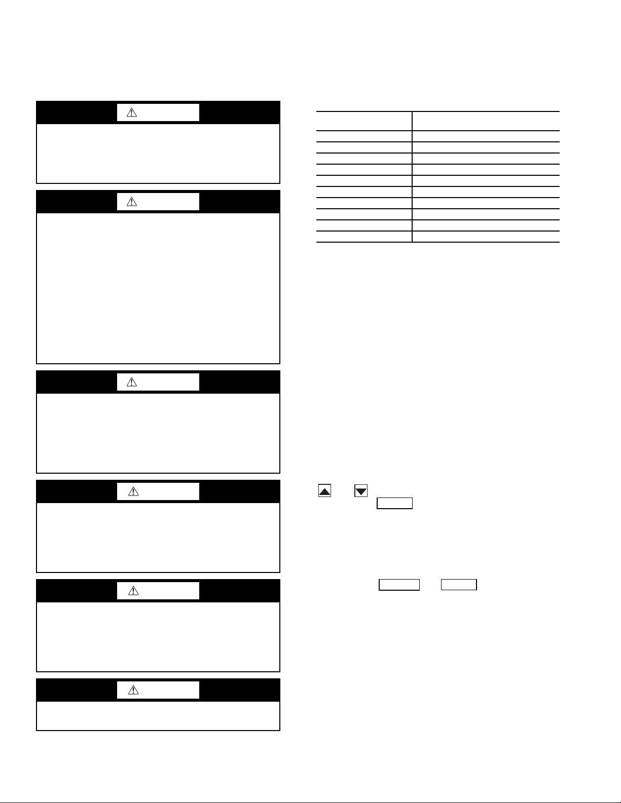
WARNING
Electrical shock can cause personal injury and death. Shut
off all power to this equipment during installation and
service. There may be more than one disconnect switch.
Tag all disconnect locations to alert others not to restore
power until work is completed.
WARNING
DO NOT VENT refrigerant relief valves within a building.
Outlet from relief valves must be vented outdoors in
accordance with the latest edition of ANSI/ASHRAE
(American National Standards Institute/American Society
of Heating, Refrigeration and Air Conditioning Engineers)
15 (Safety Code for Mechanical Refrigeration). The
accumulation of refrigerant in an enclosed space can
displace oxygen and cause asphyxiation. Provide adequate
ventilation in enclosed or low overhead areas. Inhalation of
high concentrations of vapor is harmful and may cause
heart irregularities, unconsciousness or death. Misuse can
be fatal. Vapor is heavier than air and reduces the amount
of oxygen available for breathing. Product causes eye and
skin irritation. Decomposition products are hazardous.
WARNING
DO NOT attempt to unbraze factory joints when servicing
this equipment. Compressor oil is flammable and there is
no way to detect how much oil may be in any of the
refrigerant lines. Cut lines with a tubing cutter as required
when performing service. Use a pan to catch any oil that
may come out of the lines and as a gage for how much oil
to add to system. DO NOT re-use compressor oil.
CAUTION
This unit uses a microprocessor-based electronic control
system. Do not use jumpers or other tools to short out
components, or to bypass or otherwise depart from recommended procedures. Any short-to-ground of the control
board or accompanying wiring may destroy the electronic
modules or electrical components.
CAUTION
Puron® refrigerant (R-410A) systems operate at higher
pressures than standard R-22 systems. Do not use R-22 service equipment or components on Puron refrigerant equipment. If service equipment is not rated for Puron
refrigerant, equipment damage or personal injury may
result.
CAUTION
GENERAL
This publication contains Controls Start-Up, Service,
Operation, and Troubleshooting information for the Gemini™
Select 38AP condensing units with ComfortLink controls. See
Table 1 for unit size information.
Table 1 — Unit Sizes
38AP UNIT SIZE
025 25
027 27
030 30
040 40
050 50
060 60
070 70
080 80
090 90
100 100
NOMINAL CAPACITY,
TONS, 60 Hz
CONTROLS
General —
the ComfortLink™ electronic control system that controls and
monitors all operations of the unit.
The control system is composed of several components as
listed in the sections below. See Fig. 1-3 for typical control box
drawing. See Fig. 4-17 for power and control wiring.
The 38AP air-cooled condensing unit contains
Conventions Used in This Manual — The follow-
ing conventions for discussing configuration points for the
local display (scrolling marquee or Navigator™ accessory)
will be used in this manual.
Point names will be written with the mode name first, then
any sub-modes, then the point name, each separated by an
arrow symbol (. Names will also be shown in bold
and italics. As an example, the Lead/Lag Circuit Select Point,
which is located in the Configuration mode, Option sub-mode,
would be written as Configuration OPT2LLCS.
This path name will show the user how to navigate through
the local display to reach the desired configuration. The user
would scroll through the modes and sub-modes using the
and keys. The arrow symbol in the path name represents pressing to move into the next level of the
menu structure.
When a value is included as part of the path name, it will be
shown at the end of the path name after an equals sign. If the
value represents a configuration setting, an explanation will
be shown in parenthesis after the value. As an example,
ConfigurationOPT2LLCS = 2 (Circuit A leads).
Pressing the and keys simultaneously
will scroll an expanded text description of the point name or
value across the display. The expanded description is shown in
the local display tables but will not be shown with the path
names in text.
The CCN (Carrier Comfort Network
referenced in the local display tables for users configuring the
unit with CCN software instead of the local display. The CCN
tables are located in Appendix B of the manual.
®
) point names are also
Refrigerant charge must be removed slowly to prevent loss
of compressor oil that could result in compressor failure.
2
Page 3
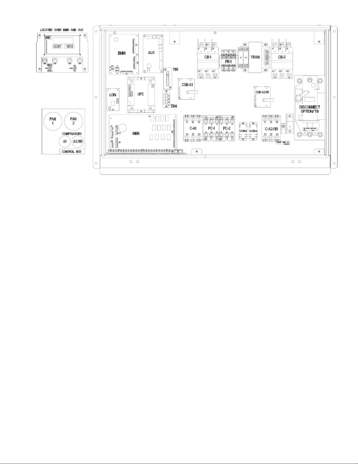
Fig. 1 — Component Arrangement — Unit Sizes 025-030
LEGEND
AUX — Auxiliary
C—Contactor
CB — Circuit Breaker
CCHR — Crankcase Heater Relay
CSB — Current Sensor Board
EMM — Energy Management Module
EQUIP GND — Equipment Ground
FB — Fuse Block
FC — Fan Contactor
LON — Local Operating Network
MBB — Main Base Board
SW — Switch
TB — Terminal Block
TRAN — Transformer
UPC — Unitary Protocol Converter
3
Page 4
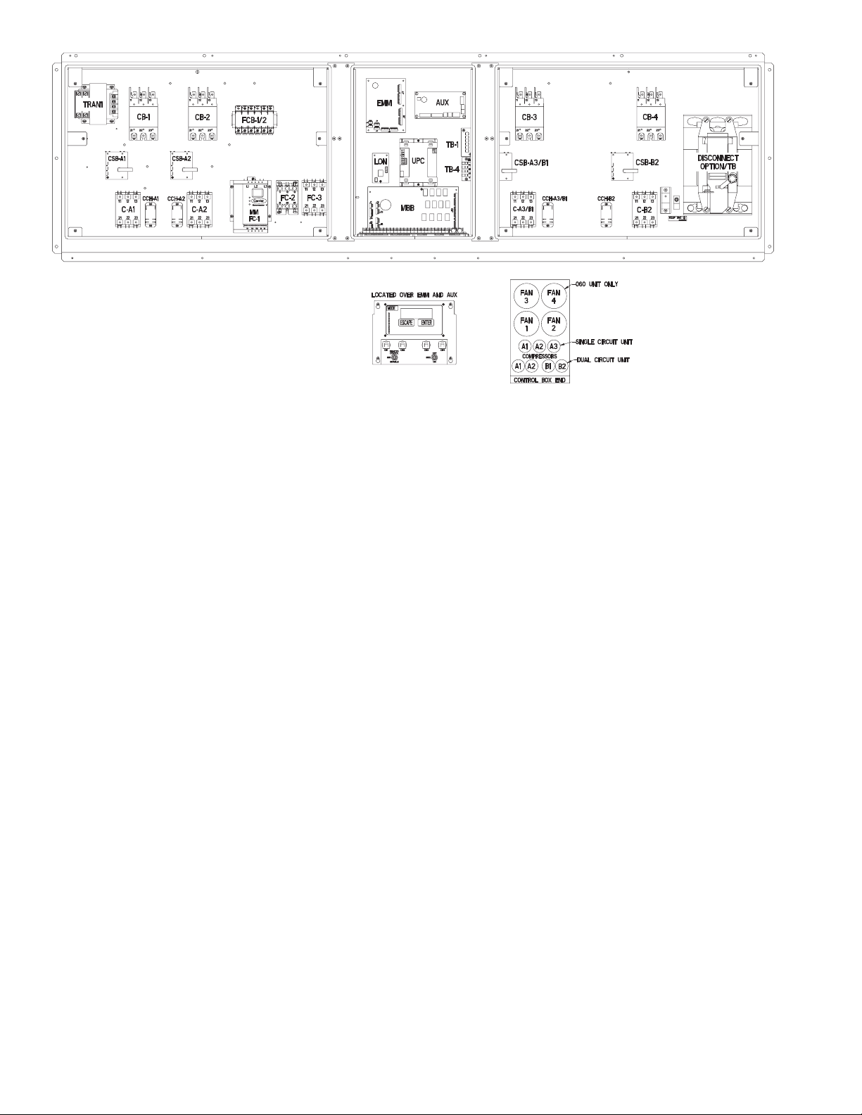
Fig. 2 — Component Arrangement — Unit Sizes 040-060
LEGEND
AUX — Auxiliary
C—Contactor
CB — Circuit Breaker
CCH — Crankcase Heater Relay
CSB — Current Sensor Board
EMM — Energy Management Module
EQUIP GND — Equipment Ground
FC — Fan Contactor
FCB — Fan Circuit Breaker
LON — Local Operating Network
MBB — Main Base Board
MM — Motormaster
®
SW — Switch
TB — Terminal Block
TRAN — Transformer
UPC — Unitary Protocol Converter
4
Page 5
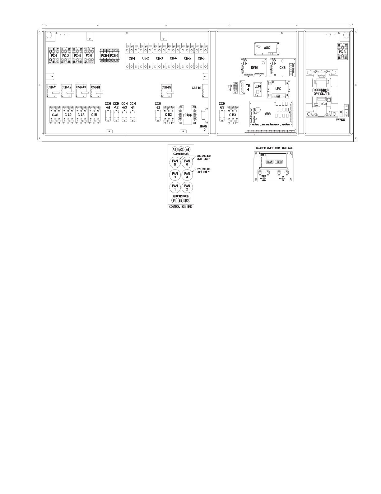
Fig. 3 — Component Arrangement — Unit Sizes 070-100
LEGEND
AUX — Auxiliary
C—Contactor
CB — Circuit Breaker
CCH — Crankcase Heater Relay
CSB — Current Sensor Board
CXB — Compressor Expansion Board
EMM — Energy Management Module
EQUIP GND — Equipment Ground
FC — Fan Contactor
FCB — Fan Circuit Breaker
LON — Local Operating Network
MBB — Main Base Board
SW — Switch
TB — Terminal Block
TRAN — Transformer
UPC — Unitary Protocol Converter
5
Page 6
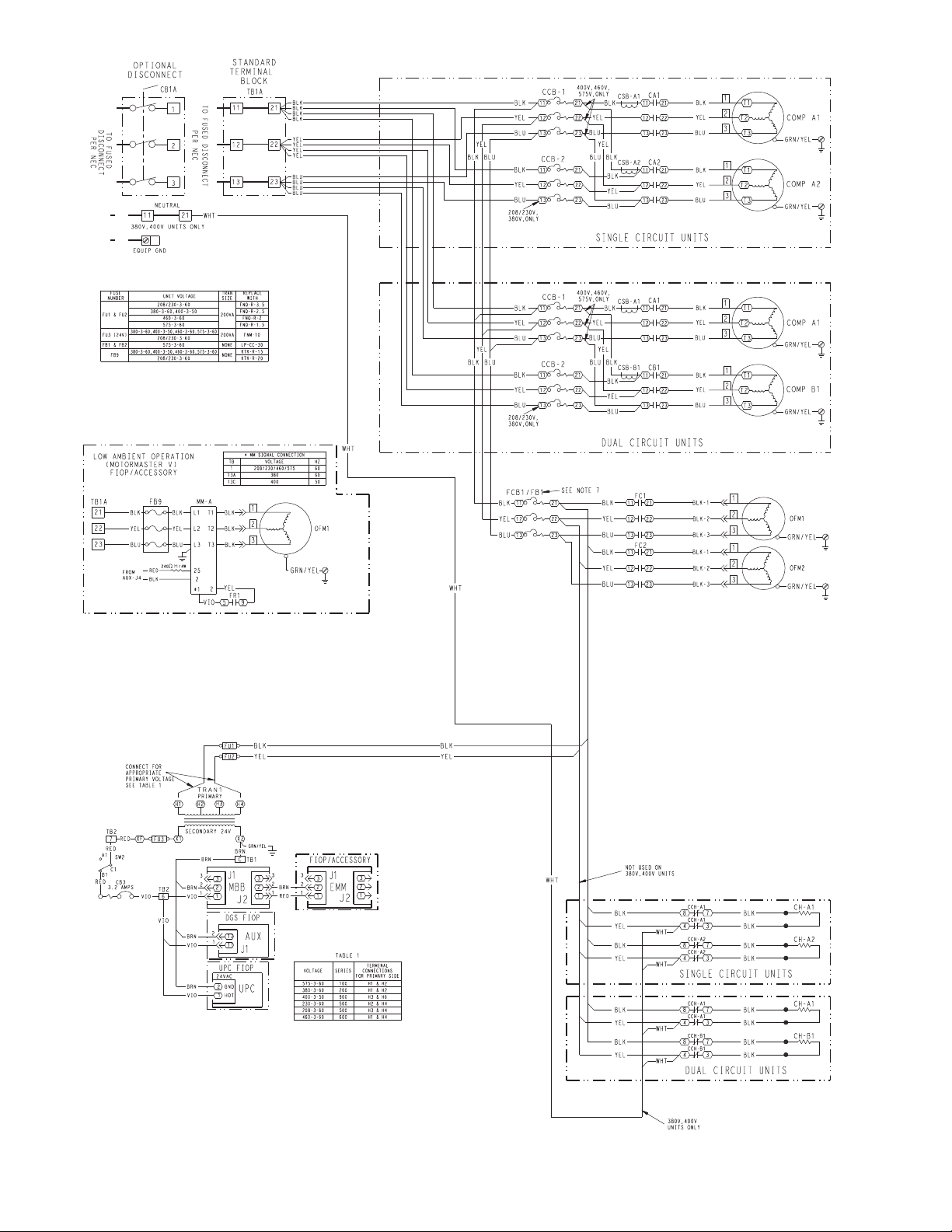
Fig. 4 — Power Wiring Schematic — 38APS,APD025-030
6
Page 7
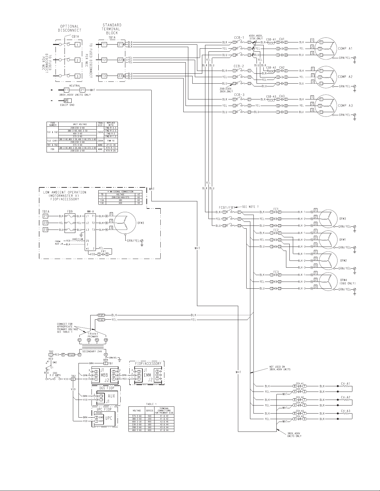
Fig. 5 — Power Wiring Schematic — 38APS040,050
7
Page 8
8
Fig. 6 — Power Wiring Schematic — 38APD040-060
Page 9
9
Fig. 7 — Power Wiring Schematic — 38APD070-100
Page 10
10
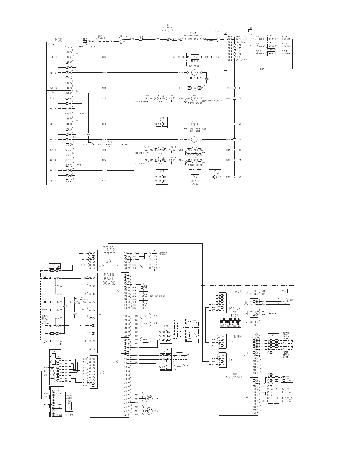
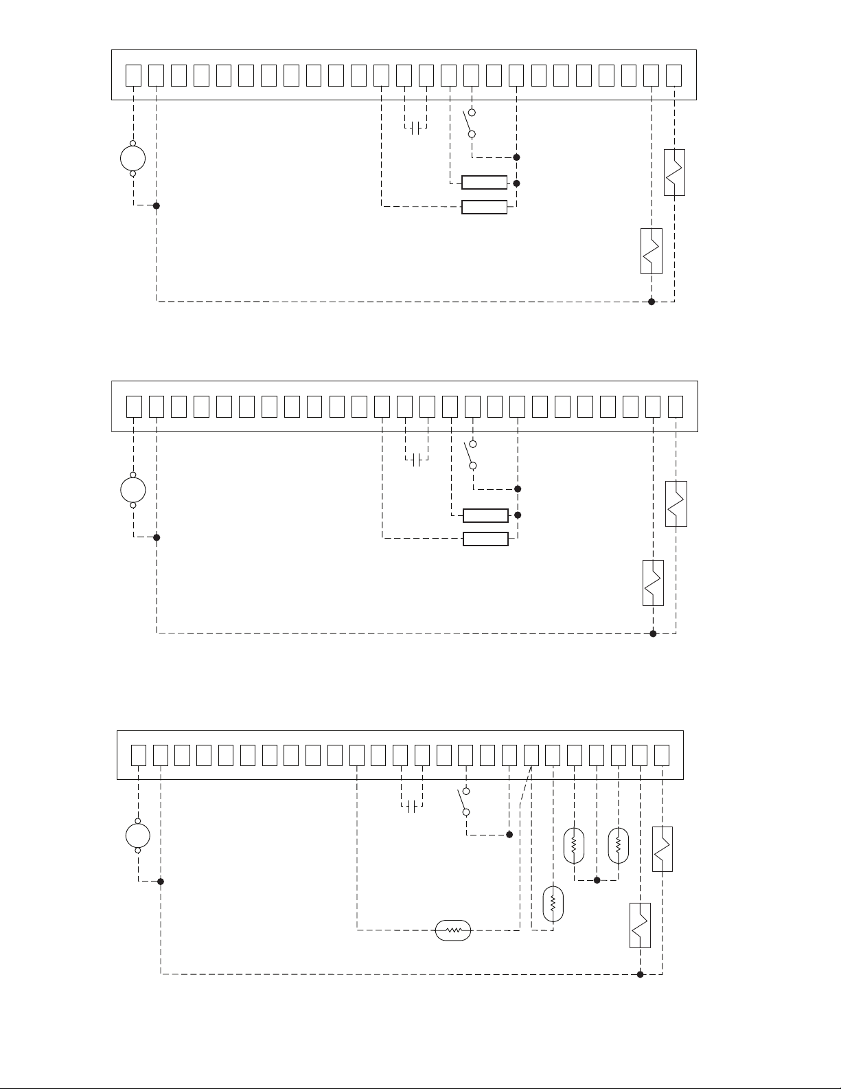
Fig. 8 — Control Wiring Schematic — 38APS025-050
Page 11
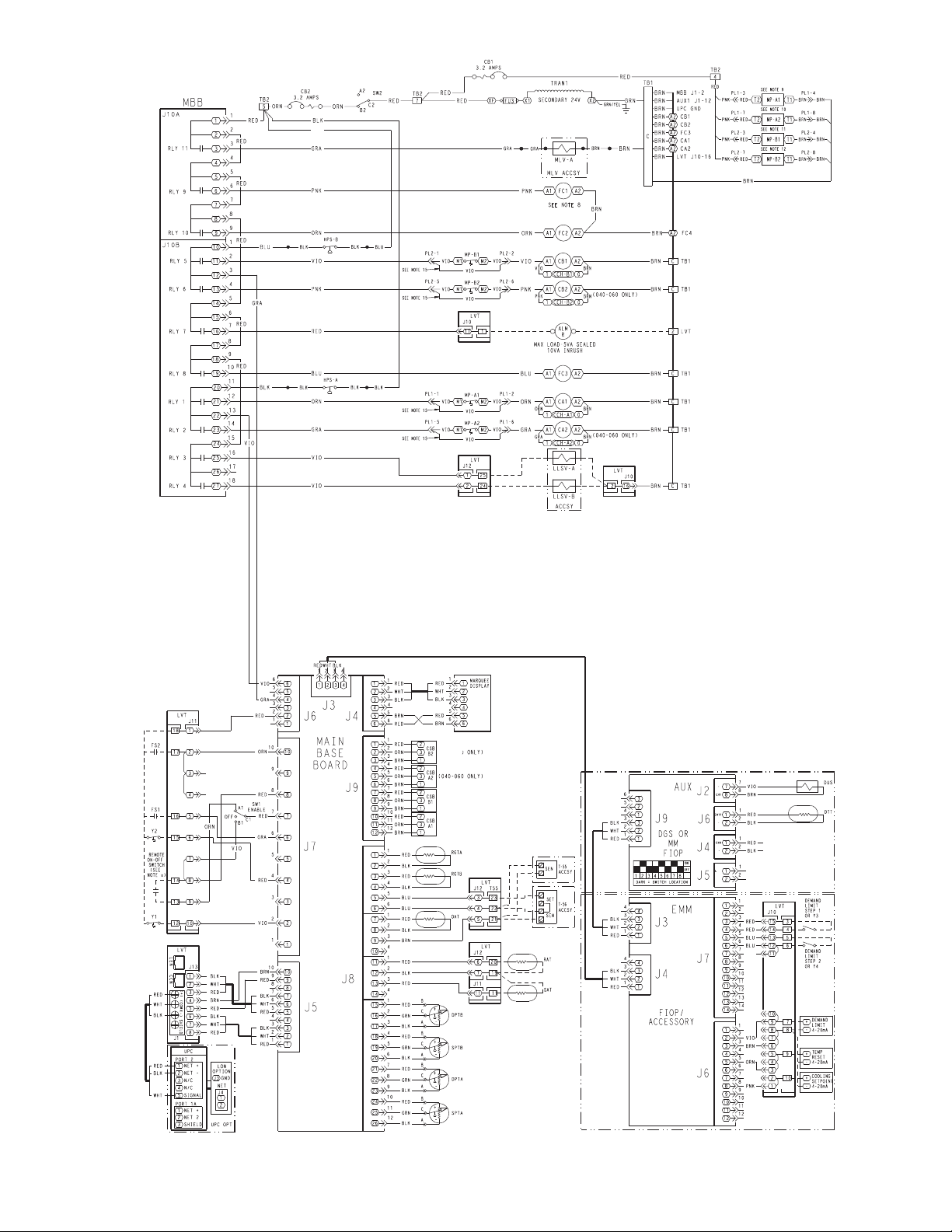
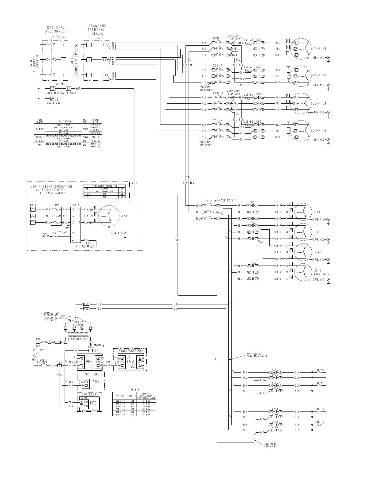
Fig. 9 — Control Wiring Schematic — 38APD025-060
11
Page 12
12
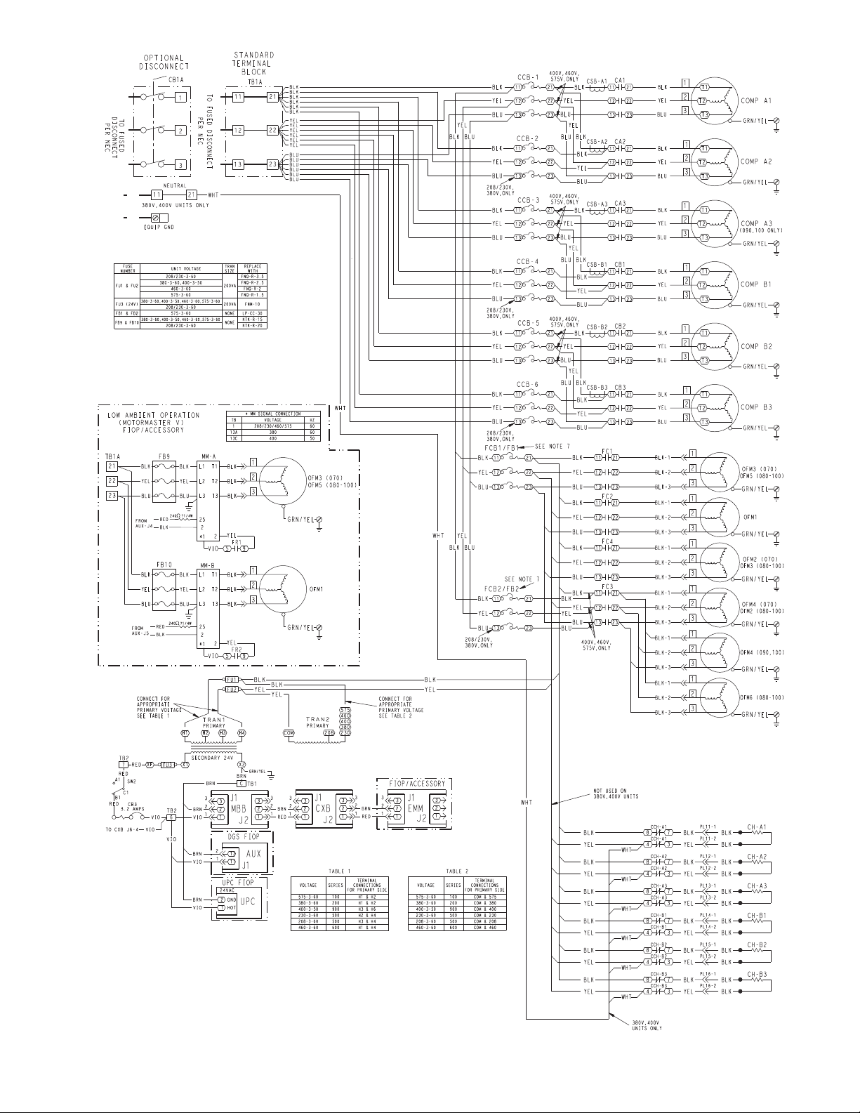
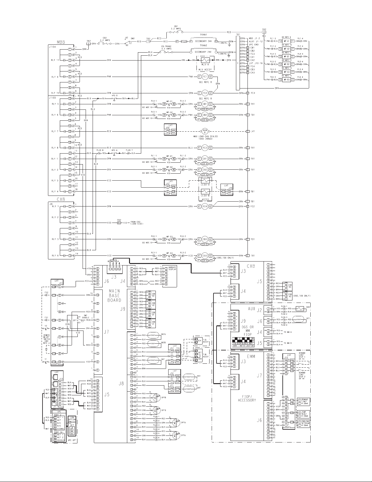
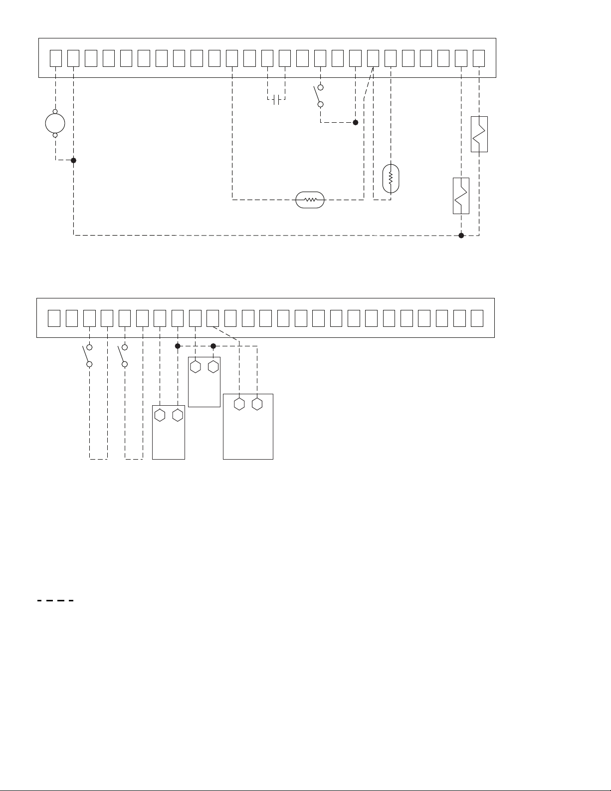
Fig. 10 — Control Wiring Schematic — 38APD070-100
Page 13

Legend and Notes for Fig. 4-10
LEGEND NOTES:
ACCSY — Accessory
ALM — Alarm
AMPS — Amperes
AUX — Auxiliary
C—Contactor
CB — Circuit Breaker
CCB — Compressor Circuit Breaker
CCH — Crankcase Heater Relay
CH — Crankcase Heater
COMP — Compressor
CSB — Current Sensor Board
CXB — Compressor Expansion Module
DGS — Digital Scroll
DPT — Discharge Pressure Transducer
DTT — Discharge Temperature Thermistor
DUS — Digital Unloaded Solenoid
EMM — Energy Management Module
EQUIP GND — Equipment Ground
FB — Fuse Block
FC — Fan Contactor
FCB — Fan Circuit Breaker
FIOP — Factory-Installed Option
FR — Fan Relay
FS — Fan Status
FU — Fuse
GND — Ground
HPS — High Pressure Switch
LLSV — Liquid Line Solenoid Valve
LV T — Low Voltage Terminal
MBB — Main Base Board
MLV — Minimum Load Valve
MM — Motormaster
MP — Modular Motor Protector
NEC — National Electrical Code
OAT — Outdoor Air Thermistor
OFM — Outdoor Fan Motor
OPT — Option
PL — Plug
RAT — Return Air Temperature
RGT — Return Gas Temperature
RLY —
SAT — Supply Air Temperature
SEN — Sensor Terminal Block
SET — Set Point Terminal Block
SPT — Suction Pressure Transducer
SW — Switch
TB — Terminal Block
TEMP — Temperature
TRAN — Transformer
UPC — Unitary Protocol Converter
Y—Cool Stage
Relay
1. Factory wiring is in accordance with UL (Underwriters Laboratories) 1995 standards. Any field modifications or additions
must be in compliance with all applicable codes.
2. Use 75 C minimum wire for field power supply.
3. All field interlock contacts must have a minimum rating of
2 amps at 24-vac sealed. See field interlock wiring.
4. Compressor and fan motors are thermally protected. Threephase motors protected against single-phase conditions.
5. Terminals 13 and 14 of LVT are for field connection of remote
on-off. The contact must be rated for dry circuit application
capable of handling a 5-vdc, 1 mA to 20 mA load.
6. For 500 series unit operation at 208-3-60 line voltage, TRAN1
primary connections must be moved to terminals H3 and H4.
7. For 575-3-60 units, fan circuit breakers FCB1 and FCB2 are
replaced with fuse blocks FB1 and FB2.
8. For units with low ambient Motormaster
option or field-installed acessory, fan contactors FC1 and FC2
are replaced with fan relays FR1 and FR2.
9. MP-A1 not used in the following units:
070-100: 400-v, 460-v units without digital scroll
10. MP-A2 not used in the following units:
070-100: 400-v, 460-v
11. MP-B1 not used in the following units:
070: all units
080-100: 400-v, 460-v
12. MP-B2 not used in the following units:
070: all units
080-100: 400-v, 460-v
13. MP-A3 not used in the following units:
090,100: 400-v, 460-v
14. MP-B3 not used in the following units:
070: all units
080-100: 400-v, 460-v
15. Jumper plug required when modular motor protector is not
used.
®
V factory-installed
13
Page 14
OUTSIDE
AIR
DUCT
SUPPLY
RETURN
AIR
MAT/RAT SATFS1*
FAN
EVAPORATOR
COIL
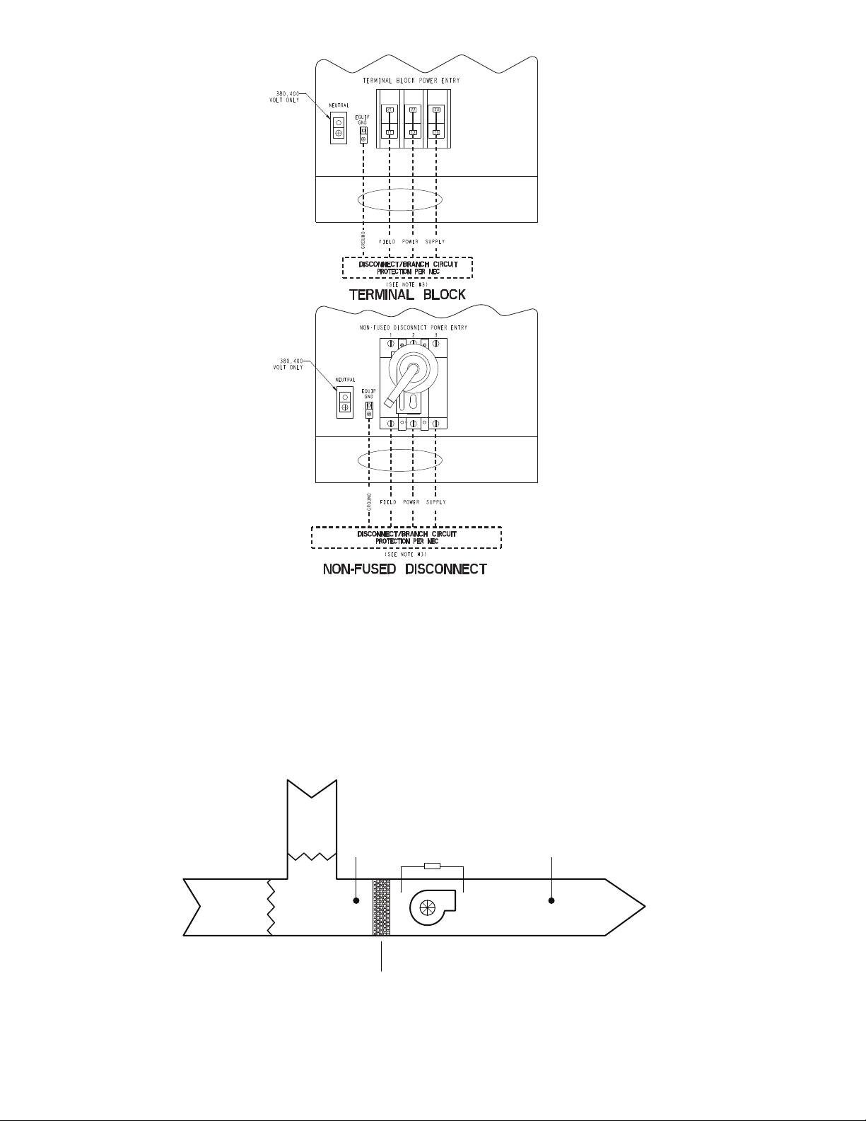
Fig. 11 — Field Power Wiring
LEGEND
NOTES:
1. Factory wiring is in accordance with UL 1995 standards. Field modifications
or additions must be in compliance with all applicable codes.
2. All units or modules have single point primary power connection. Main
power must be supplied from a field or factory-supplied disconnect.
3. Wiring for main field supply must be rated 75 C. Use copper conductors only.
a. Incoming wire size range for terminal block with MCA (minimum circuit
amps) up to 175 amps is 14 AWG (American Wire Gage) to 2/0.
b. Incoming wire size range for terminal block with MCA from 175.1 amps to
420 amps is 2 AWG to 600 kcmil.
c. Incoming wire size range for non-fused disconnect with MCA up to
100 amps is 14 AWG to 1/0.
d. Incoming wire size range for non-fused disconnect with MCA from
100.1 amp to 200 amps is 6 AWG to 350 kcmil.
e. Incoming wire size range for non-fused disconnect with MCA from
200.1 amp to 450 amps is 3/0 to 500 kcmil.
4. Refer to certified dimensional drawings for exact locations of the main power
and control power entrance locations.
EQUIP GND — Equipment Ground
NEC — National Electrical Code
a38-7122
LEGEND
*FS1 can be pressure differential switch (shown), motor current detection, or sail switch.
FS1 — Fan Status Switch (24-v)
MAT — Mixed Air Temperature Sensor
RAT — Return Air Temperature Sensor
SAT — Supply Air Temperature Sensor
a38-7133
Fig. 12 — MAT/RAT and SAT Sensor Layout
14
Page 15
a38-7125
a38-7127
*See Fig. 12 for MAT/RAT and SAT location.
†Not required for single circuit units.
Fig. 15 — Constant Volume Application Wiring Diagram Space Temperature Sensor Control, Sizes 025-100
Fig. 14 — Constant Volume Application Wiring Diagram 2-Stage Thermostat Control —
with Digital Scroll Option, Sizes 025-030 or All Sizes 040-100
Fig. 13 — Constant Volume Application Wiring Diagram 2-Stage Thermostat Control, Sizes 025-030 —
without Digital Scroll Option
*Not required for single circuit units.
25242322212019181716151413
REMOTE
ON/OFF
LV T
TERMINAL
STRIP
121110987654321
ALM
R
COOL 1
COOL 2
FS 1
LLSV-A
LLSV-B
*
SEE NOTE 6
a38-7126
*See Fig. 12 for MAT/RAT and SAT location.
†Not required for single circuit units.
25242322212019181716151413
REMOTE
ON/OFF
LV T
TERMINAL
STRIP
121110987654321
ALM
R
COOL 1
FS 1
LLSV-A
LLSV-B
*
SEE NOTE 6
COOL2
121110987654321
25242322212019181716151413
LV T
TERMINAL
STRIP
SAT
FS 1
SPT
*
MAT/RAT
*
SA
†
LLSV-B
REMOTE
ON/OFF
ALM
R
15
LLSV-A
SEE NOTE 6
Page 16
25242322212019181716151413
REMOTE
ON/OFF
LV T
TERMINAL
STRIP
121110987654321
ALM
R
FS 1
LLSV-A
SEE NOTE 6
SAT
*
MAT/RAT
*
LLSV-B
†
a38-7128
Fig. 16 — Variable Air Volume Application Wiring Diagram, Sizes 025-100
*See Fig. 12 for MAT/RAT and SAT location.
†Not required for single circuit units.
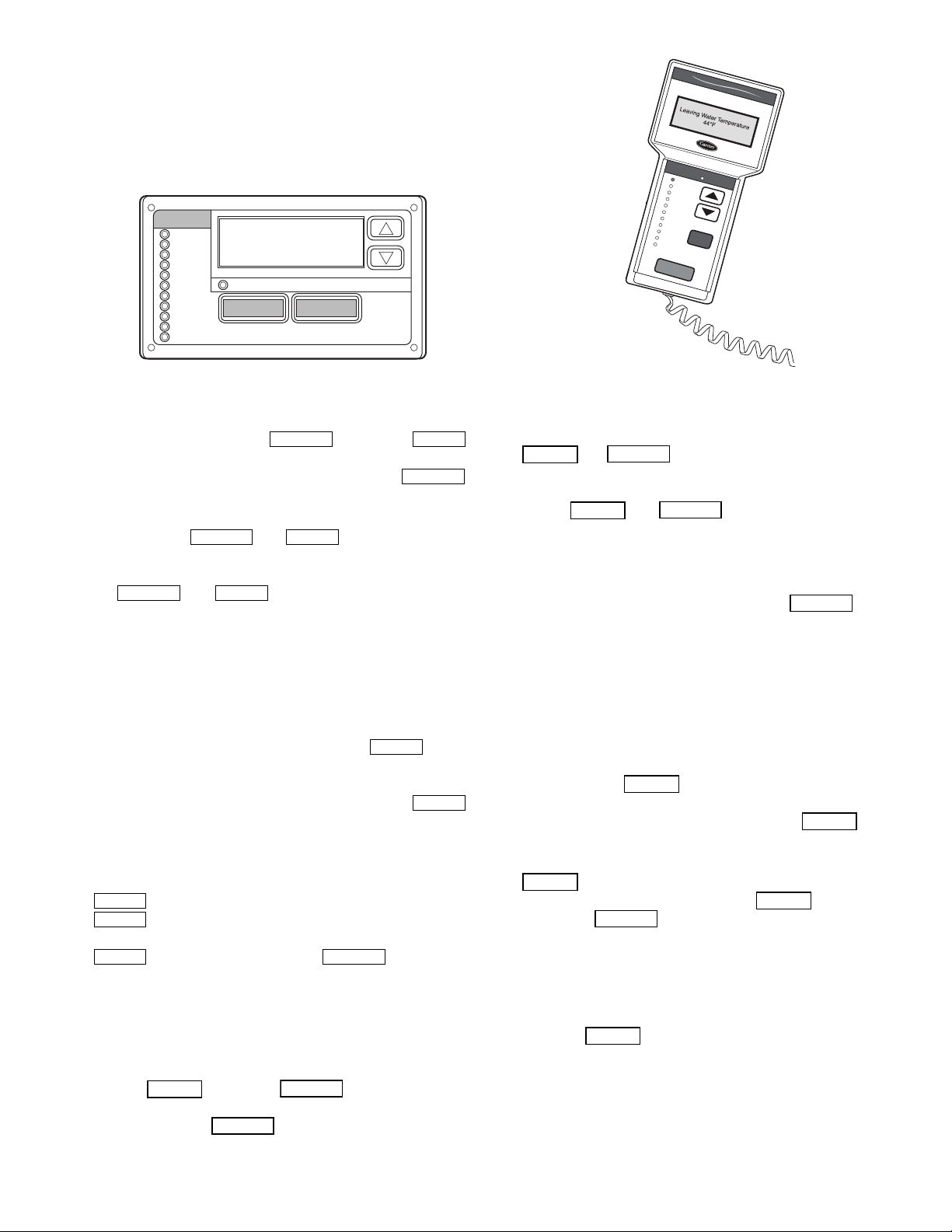
Fig. 17 — Optional Energy Management Module Wiring
a38-7129
Legend and Notes for Fig. 13-17
LEGEND
NOTES:
1. Factory wiring is in accordance with UL 1995 standards. Field
modifications or additions must be in compliance with all applicable codes.
2. All units or modules have single point primary power connection. Main power must be supplied from a field or factorysupplied disconnect.
3. Wiring for main field supply must be rated 75 C. Use copper
conductors only.
a. Incoming wire size range for terminal block with MCA (mini-
mum circuit amps) up to 175 amps is 14 AWG (American
Wire Gage) to 2/0.
b. Incoming wire size range for terminal block with MCA from
175.1 amps to 420 amps is 2 AWG to 600 kcmil.
c. Incoming wire size range for non-fused disconnect with MCA
up to 100 amps is 14 AWG to 1/0.
d. Incoming wire size range for non-fused disconnect with MCA
from 100.1 amp to 200 amps is 6 AWG to 350 kcmil.
e. Incoming wire size range for non-fused disconnect with MCA
from 200.1 amp to 450 amps is 3/0 to 500 kcmil.
4. Terminals 1 and 2 of the LVT are for the alarm relay. The maximum load allowed for the alarm relay is 5-va sealed and 10-va
inrush at 24-v. Field power supply is not required.
5. Refer to certified dimensional drawings for exact locations of
the main power and control power entrance locations.
6. Terminals 24, 25, and 2 of the LVT are for the control of the
field-supplied LLSV. The maximum load allowed for the LLSV
is 15-va sealed and 30-va inrush at 24-v. Field power supply is
not required.
7. LLSV (24-v) should be 15-va maximum per valve as required.
8. Installation of fan status switch (FS1) is recommended.
9. The contacts for remote ON/OFF, fan status, and demand limit
options must be rated for dry circuit application capable of handling a 24-vac load up to 50 mA.
ALM R — Alarm Relay (24-v), 5-va Maximum
COOL1 — Thermostat Stage 1 (24-v)
COOL2 — Thermostat Stage 2 (24-v)
FS1 — Fan Status Switch (24-v)
LLSV — Liquid Line Solenoid Valve
LV T — Low Voltage Terminal
MAT — Mixed Air Temperature Sensor
RAT — Return Air Temperature Sensor
SA — Set Point Adjustment (T-56, T-59)
SAT — Supply Air Temperature Sensor
SPT — Space Temperature Sensor (T-55, T-56, T-59)
Field Control Wiring
LV T
TERMINAL
121110987654321
25242322212019181716151413
STRIP
–
+
TEMP
RESET
4-20 mA
–
+
–
+
DEMAND LIMIT STEP 1
DEMAND LIMIT STEP 2
DEMAND
LIMIT
4-20 mA
COOLING
SETPOINT/
CAPACITY
REQUESTED
4-20 mA
16
Page 17
Display Module Usage
Run Status
Service Test
Temperature
Pressures
Setpoints
Inputs
Outputs
Configuration
Time Clock
Operating Modes
Alarms
Alarm Status
ENTER
MODE
ESCAPE
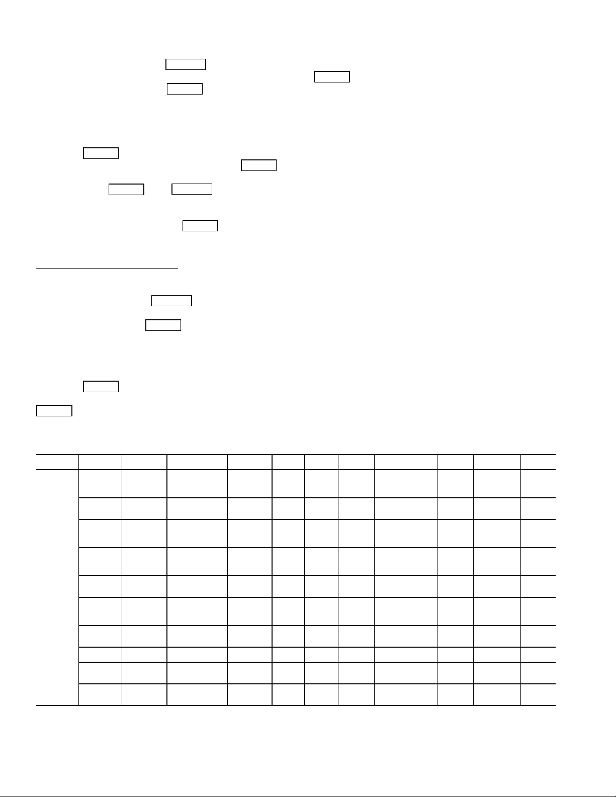
Fig. 18 — Scrolling Marquee Display
ESCAPE
ENTER
ESCAPE
ESCAPE
ENTER
ESCAPE
ENTER
ENTER
ENTER
ENTER
ENTER
ENTER
ESCAPE
ENTER
ESCAPE
ESCAPE
ENTER
ESCAPE
ENTER
ESCAPE
ESCAPE
ENTER
ENTER
ENTER
ENTER
ESCAPE
ENTER
R
un
S
ta
tu
s
S
er
vic
e
T
e
s
t
T
e
m
pe
ra
tu
r
e
s
P
res
s
u
res
S
e
tpo
ints
Inp
u
ts
O
u
tpu
ts
C
o
nfig
u
ratio
n
T
im
e
C
lo
ck
O
p
e
ra
tin
g
M
o
d
e
s
A
la
rm
s
EN
TER
ES
C
M
O
D
E
Alarm Status
Comfort
Link
Fig. 19 — Accessory Navigator Display Module
SCROLLING MARQUEE DISPLAY — This device is the
keypad interface used for accessing unit information, reading
sensor values, and testing the unit. See Fig. 18. The scrolling
marquee display is a 4-key, 4-character, 16-segment LED
(light-emitting diode) display. Eleven mode LEDs are located
on the display as well as an Alarm Status LED. See Appendix
A — Display Tables for further details.
The scrolling marquee display module provides the user interface to the ComfortLink™ control system. The display has
up and down arrow keys, an key, and an
key. These keys are used to navigate through the different levels of the display structure. See Table 2. Press the
key until the display is blank to move through the top 11 mode
levels indicated by LEDs on the left side of the display.
Pressing the and keys simultaneously
will scroll a clear language text description across the display
indicating the full meaning of each display acronym. Pressing
the and keys when the display is blank
(Mode LED level) will return the scrolling marquee display to
its default menu of rotating display items. In addition, the password will be disabled requiring that it be entered again before
changes can be made to password protected items. Clear language descriptions will be displayed in English.
When a specific item is located, the display will flash showing the operator, the item, followed by the item value and then
followed by the item units (if any). Press the key to
stop the display at the item value. Items in the Configuration
and Service Test modes are password protected. The display
will flash PASS and WORD when required. Use the
and arrow keys to enter the 4 digits of the password. The
default password is 1111.
Changing item values or testing outputs is accomplished in
the same manner. Locate and display the desired item. Press
to stop the display at the item value. Press the
key again so that the item value flashes. Use the
arrow keys to change the value or state of an item and press the
key to accept it. Press the key and the
item, value, or units display will resume. Repeat the process as
required for other items.
ACCESSORY NAVIGATOR™ DISPLAY MODULE —
The Navigator module provides a mobile user interface to the
ComfortLink™ control system, which is only available as a
field-installed accessory. The display has up and down arrow
keys, an key, and an key. These keys are
used to navigate through the different levels of the display
structure. Press the key until ‘Select a Menu Item’
is displayed to move through the top 11 mode levels indicated
by LEDs on the left side of the display. See Fig. 19.
Once within a Mode or sub-mode, a “>” indicates the cur-
rently selected item on the display screen. Pressing the
and keys simultaneously will put the Navigator module into expanded text mode where the full meaning
of all sub-modes, items and their values can be displayed. Pressing the and keys when the display says
‘Select Menu Item’ (Mode LED level) will return the Navigator
module to its default menu of rotating display items (those items
in Run Status
VIEW). In addition, the password will be disabled, requiring that it be entered again before changes can be
made to password protected items. Press the key to
exit out of the expanded text mode.
NOTE: When the Language Selection (Configuration
DISPLANG), variable is changed, all appropriate display
expansions will immediately change to the new language. No
power-off or control reset is required when reconfiguring
languages.
When a specific item is located, the item name appears on the
left of the display, the value will appear near the middle of the
display and the units (if any) will appear on the far right of the
display. Press the key at a changeable item and the value will begin to flash. Use the up and down arrow keys to change
the value, and confirm the value by pressing the key.
Changing item values or testing outputs is accomplished in
the same manner. Locate and display the desired item. Press
so that the item value flashes. Use the arrow keys to
change the value or state and press the key to accept
it. Press the key to return to the next higher level of
structure. Repeat the process as required for other items.
Items in the Configuration and Service Test modes are password protected. The words Enter Password will be displayed
when required, with 1111 also being displayed. The default
password is 0111. Use the arrow keys to change the number
and press to enter the digit. Continue with the remaining digits of the password. The password can only be
changed through CCN operator interface software such as
ComfortWORKS
®
, ComfortVIEW™ and Service Tool.
17
Page 18
Adjusting the Contrast
ESCAPE
ENTER
ENTER
ENTER
ENTER
ESCAPE
ENTER
ESCAPE
ENTER
ENTER
ENTER
ENTER
— The contrast of the display can be
adjusted to suit ambient conditions. To adjust the contrast of
the Navigator module, press the key until the display reads, “Select a menu item.” Using the arrow keys move
to the Configuration mode. Press to obtain access to
this mode. The display will read:
> TEST OFF
METR OFF
LANG ENGLISH
Pressing will cause the “OFF” to flash. Use the up
or down arrow to change “OFF” to “ON”. Pressing
will illuminate all LEDs and display all pixels in the view
screen. Pressing and simultaneously
allows the user to adjust the display contrast. Use the up or
down arrows to adjust the contrast. The screen’s contrast will
change with the adjustment. Press to accept the
change. The Navigator module will keep this setting as long as
it is plugged in to the LEN bus.
Adjusting the Backlight Brightness
— The backlight of the
display can be adjusted to suit ambient conditions. The factory
default is set to the highest level. To adjust the backlight of the
Navigator module, press the key until the display
reads, “Select a menu item.” Using the arrow keys move to the
Configuration mode. Press to obtain access to this
mode. The display will read:
> TEST OFF
METR OFF
LANG ENGLISH
Pressing will cause the “OFF” to flash. Use the up
or down arrow keys to change “OFF” to “ON”. Pressing
will illuminate all LEDs and display all pixels in the
view screen. Pressing the up and down arrow keys simultaneously allows the user to adjust the display brightness. Use the
up or down arrow keys to adjust screen brightness. Press
to accept the change. The Navigator module will
keep this setting as long as it is plugged in to the LEN bus.
Main Base Board (MBB) — See Fig. 20. The MBB is
the heart of the ComfortLink control system. It contains the
major portion of operating software and controls the operation
of the machine. The MBB continuously monitors input/output
channel information received from its inputs and from all other
modules. The MBB receives inputs from the discharge and
suction pressure transducers, current sensor boards (CSB) and
thermistors. See Table 3. The MBB also receives the discrete
inputs from the thermostat contacts and other status switches.
See Table 4. The MBB also controls several outputs. Information is transmitted between modules via a 3-wire communication bus or LEN (Local Equipment Network). The CCN (Carrier Comfort Network
®
) bus is also supported. Connections to
both LEN and CCN buses are made at the LVT (low voltage
terminal) terminal strip.
Current Sensor Board (CSB) — The CSB is used to
monitor the status of the compressors by measuring current and
providing an analog input to the main base board (MBB) or
compressor expansion module (CXB).
Energy Management Module (EMM) — The EMM
module is available as a factory-installed option or as a fieldinstalled accessory. The EMM module receives 4 to 20 mA
inputs for the percent capacity, temperature reset, cooling set
point, and demand limit functions. The EMM module also receives the switch inputs for the field-installed 2-stage demand
limit and when two thermostats are used for one unit. The
EMM module communicates the status of all inputs with the
MBB, and the MBB adjusts the control point, capacity limit,
and other functions according to the inputs received.
Table 2 — Scrolling Marquee Display Menu Structure*
MODE
SUB-MODE
LEGEND
Ckt — Circuit
*Throughout this text, the location of items in the menu structure will be described in
the following format:
Item Expansion (Mode Name Sub-mode N ame ITEM)
RUN
STATUS
Auto
Display
(VIEW)
Machine
Hours/Starts
(RUN)
Compressor
Run Hours
(HOUR)
Compressor
Starts
(STRT)
Preventive
Maintenance
(PM)
Software
Ver si on
(VERS)
SERVICE
TEST
Manual
Mode
On/Off
(TEST)
Unit
Outputs
(OUTS)
Ckt A Comp
Tests
(CMPA)
Ckt B Comp
Tests
(CMPB)
TEMPERATURES PRESSURES
Unit
Temperatures
(UNIT)
Ckt A
Temperatures
(CIR.A)
Ckt B
Temperatures
(CIR.B)
Ckt A
Pressures
(PRC.A)
Ckt B
Pressures
(PRC.B)
SET
POINTS
Cooling
(COOL)
Head
Pressure
(HEAD)
INPUTS OUTPUTS CONFIGURATION
Unit
Discrete
(GEN.I)
Ckt A/B
(CRCT)
Unit
Analog
(4-20)
Unit
Discrete
(GEN.O)
Ckt A
(CIR.A)
Ckt B
(CIR.B)
Display
(DISP)
Unit Configuration
(UNIT)
CCN Network
(CCN)
Options 1
(OPT1)
Options 2
(OPT2)
Motormaster
(M.MST)
Reset Cool
Temperature
(RSET)
Set Point Select
(SLCT)
Service
Configuration
(SERV)
Broadcast
Configuration
(BCST)
TIME
CLOCK
Unit Time
(TIME)
Unit Date
(DATE)
Daylight
Saving
Time
(DST)
Local
Holiday
Schedules
(HOL.L)
Schedule
Number
(SCH.N)
Local
Schedule
Number
(SCH.L)
Schedule
Overide
(OVR)
OPERATING
MODES
Modes
(MODE)
Task State
(TSKS)
ALARMS
Current
(CRNT)
Reset
Alarms
(RCRN)
Alarm
History
(HIST)
18
Page 19
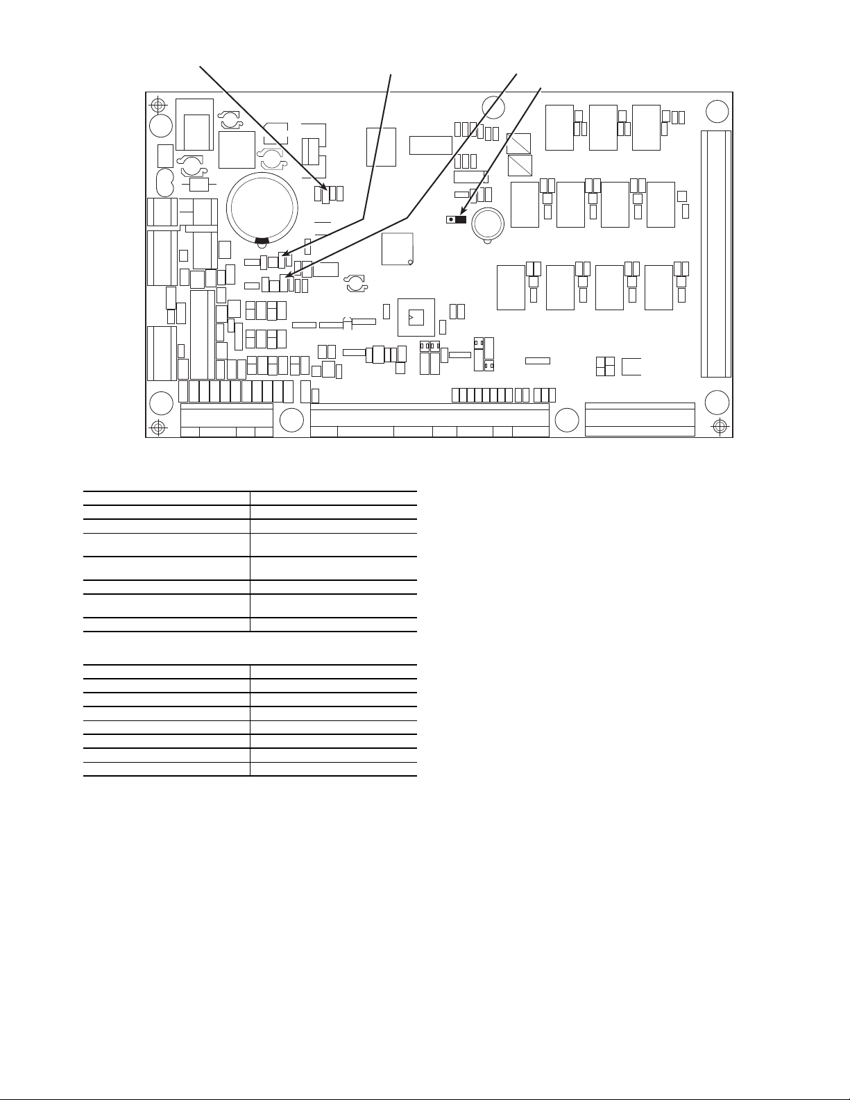
Table 3 — Thermistor Designations
CEPL130346-01
STATUS
LEN
J1
J2
J4
J3
J5
J6
J7
J8
J9
J10
CCN
RED LED - STATUS GREEN LED -
LEN (LOCAL EQUIPMENT NETWORK)
YELLOW LED CCN (CARRIER COMFORT NETWORK)
INSTANCE JUMPER
K11
K10 K9
K8
K7
K6
K5
K4
K3 K2
K1
Fig. 20 — Main Base Board
THERMISTOR INPUT PIN CONNECTION POINT
Return Air (Accessory) MBB J8-11,12; LVT 19,20
Supply Air (Accessory) MBB J8-12,13; LVT 11,19
Compressor Return Gas
Temperature A
Compressor Return Gas
Temperature B
Outdoor Air Temperature MBB J8-7,8
Discharge Temperature
(Digital Option Only)
Space Temperature (Accessory) MBB J8-5,6; LVT 21,22
Table 4 — Switch Inputs
Thermostat Y1 (Accessory) LVT 12,18
Thermostat Y2 (Accessory) LVT 15,18
Fan Status 1 (Accessory) LVT 16,18
Fan Status 2 (Accessory) LVT 17,18
Remote On/Off LVT 13,14
High Pressure Switch A MBB J6-4
High Pressure Switch B MBB J6-6
SWITCH INPUT PIN CONNECTION POINT
Compressor Expansion Module (CXB) — The
CXB is only used on unit sizes 070-100 to provide additional
inputs and outputs for fans and compressors when the unit has
more than 4 compressors.
AUX Board (AUX) — The AUX is used with the digital
scroll option and the low ambient head pressure option. It provides additional inputs and outputs for digital scroll control
along with analog outputs to control head pressure control fan
speeds.
Enable/Off/Remote Contact Switch — The Enable/
Off/Remote Contact switch is a 3-position switch used to
control the unit. When switched to the Enable position, the unit
is under its own control. Move the switch to the Off position to
shut the unit down. Move the switch to the Remote Contact position and a field-installed dry contact can be used to start the
unit. The contacts must be capable of handling a 24 vac, 50 mA
load. In the Enable and Remote Contact (dry contacts closed)
MBB J8-1,2
MBB J8-3,4
AUX J6- 1, 2
positions, the unit is allowed to operate and respond to the
scheduling configuration, CCN configuration and set point
data. See Fig. 21.
Emergency On/Off Switch — The Emergency On/Off
switch should only be used when it is required to shut the
unit off immediately. Power to the MBB, CXB, AUX, EMM,
and scrolling marquee display is interrupted when this switch is
off and all outputs from these modules will be turned off.
Board Addresses — The main base board (MBB) has a
3-position Instance jumper that must be set to ‘1.’ All other
boards have 4-position DIP switches. All switches are set to
‘On’ for all boards.
Control Module Communication
RED LED — Proper operation of the control boards can be
visually checked by looking at the red status LEDs
(light-emitting diodes). When operating correctly, the red status
LEDs should be blinking in unison at a rate of once every
2 seconds. If the red LEDs are not blinking in unison, verify
that correct power is being supplied to all modules. Be sure that
the main base board (MBB) is supplied with the current software. If necessary, reload current software. If the problem still
persists, replace the MBB. A red LED that is lit continuously or
blinking at a rate of once per second or faster indicates that the
board should be replaced.
GREEN LED — The MBB has one green LED. The Local
Equipment Network (LEN) LED should always be blinking
whenever power is on. All other boards have a LEN LED
which should be blinking whenever power is on. Check LEN
connections for potential communication errors at the board J3
and/or J4 connectors. Communication between modules is
accomplished by a 3-wire sensor bus. These 3 wires run in
parallel from module to module. The J4 connector on the MBB
provides both power and communication directly to the
marquee display only.
YELLOW LED — The MBB has one yellow LED. The
Carrier Comfort Network (CCN) LED will blink during times
of network communication.
19
Page 20
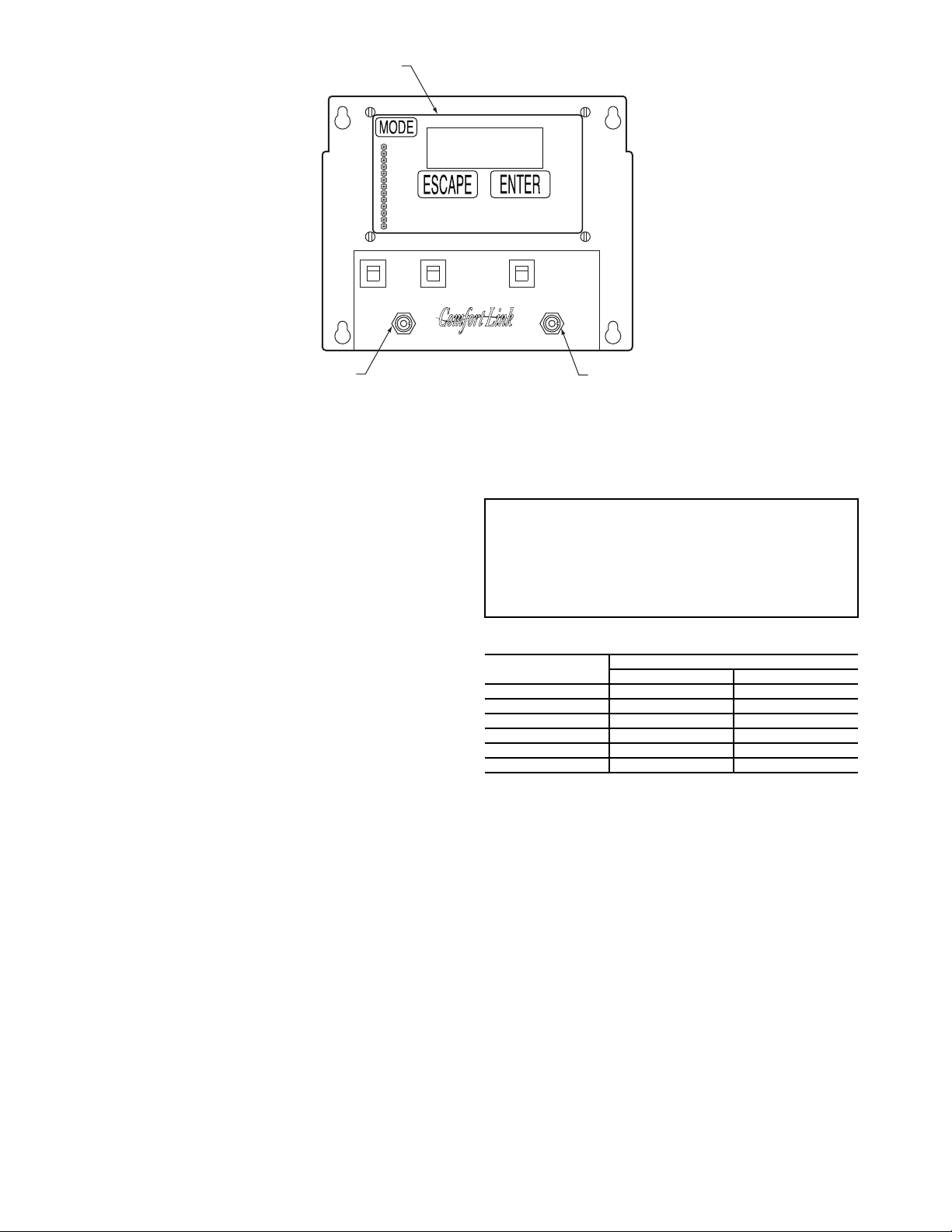
Carrier Comfort Network® (CCN) Interface —
CB1
REMOTE
CONTROL
ENABLE
SCROLLING MARQUEE
DISPLAY
ENABLE/OFF/REMOTE
CONTACT SWITCH
EMERGENCY
ON-OFF SWITCH
SW1 OFF
OFF
ON
SW2
CB2 CB3
Fig. 21 — Scrolling Marquee, Enable/Off/Remote Contact Switch, and Emergency On/Off Switch Locations
LEGEND
CB — Circuit Breaker
SW — Switch
The 38AP units can be connected to the CCN if desired. The
communication bus wiring is a shielded, 3-conductor cable
with drain wire and is supplied and installed in the field. See
Table 5. The system elements are connected to the communication bus in a daisy chain arrangement. The positive pin of
each system element communication connector must be wired
to the positive pins of the system elements on either side of it.
This is also required for the negative and signal ground pins of
each system element. Wiring connections for CCN should be
made at LVT. Consult the CCN Contractor’s Manual for further information.
NOTE: Conductors and drain wire must be 20 AWG (American Wire Gage) minimum stranded, tinned copper. Individual
conductors must be insulated with PVC, PVC/nylon, vinyl,
Teflon, or polyethylene. An aluminum/polyester 100% foil
shield and an outer jacket of PVC, PVC/nylon, chrome vinyl,
or Teflon with a minimum operating temperature range of
–20 C to 60 C is required. Wire manufactured by Alpha (2413
or 5463), American (A22503), Belden (8772), or Columbia
(02525) meets the above mentioned requirements.
It is important when connecting to a CCN communication
bus that a color coding scheme be used for the entire network
to simplify the installation. It is recommended that red be used
for the signal positive, black for the signal negative, and white
for the signal ground. Use a similar scheme for cables containing different colored wires.
At each system element, the shields of its communication
bus cables must be tied together. If the communication bus is
entirely within one building, the resulting continuous shield
must be connected to a ground at one point only. If the communication bus cable exits from one building and enters another,
the shields must be connected to grounds at the lightning
suppressor in each building where the cable enters or exits the
building (one point per building only). To connect the unit to
the network:
1. Turn off power to the control box.
2. Cut the CCN wire and strip the ends of the red (+), white
3. Connect the red wire to (+) terminal on LVT of the plug,
(ground), and black (–) conductors. (Substitute appropriate colors for different colored cables.)
the white wire to COM terminal, and the black wire to the
(–) terminal.
20
4. The RJ14 CCN connector on LVT can also be used, but is
only intended for temporary connection (for example, a
laptop computer running Service Tool).
IMPORTANT: A shorted CCN bus cable will prevent some
routines from running and may prevent the unit from starting. If abnormal conditions occur, unplug the connector. If
conditions return to normal, check the CCN connector and
cable. Run new cable if necessary. A short in one section of
the bus can cause problems with all system elements on the
bus.
Table 5 — CCN Communication Bus Wiring
MANUFACTURER
Alpha 1895 —
American A21451 A48301
Belden 8205 884421
Columbia D6451 —
Manhattan M13402 M64430
Quabik 6130 —
Regular Wiring Plenum Wiring
PART N O.
OPERATING DATA
Sensors — The electronic control uses 3 to 7 thermistors to
sense temperatures for controlling unit operation. See Table 3.
These sensors are outlined below. Three different thermistor
curves are utilized depending on the thermistor and the configuration of the input. The three different types are 5 kat 77 F
(25 C), 10 kat 77 F (25 C), and 86 k at 77 F (25 C). See
Thermistors section on page 49 for additional information.
RETURN AIR TEMPERATURE (RAT) ACCESSORY
(Part No. 33ZCSENSAT) — A return air temperature sensor
is required for unit sizes 040-100 and all units equipped with
the digital scroll option. The sensor is field installed in the
indoor unit and wired to the LVT of the unit to measure the air
temperature entering the evaporator coil. The sensor should be
located directly in front of the evaporator coil after an outside
air intake.
The RAT sensor consists of a thermistor encased within a
stainless steel probe. See Fig. 22. The sensor probe is 6 in.
nominal length with 114 in. of unshielded, 2-conductor
18 AWG twisted-pair cables. The sensor temperature range is
–40 to 245 F with a nominal resistance of 10,000 ohms at 77 F.
The sensor has with an accuracy of ±0.36 F.
Page 21

Fig. 22 — 33ZCSENSAT Sensor
.39
.08
FOAM GASKET
.40'' O.D.
.250 ±.01 Dia
5.5 ±.5
PLENUM RATED CABLE
114'' ±6
3.00
3.90
.175 DIA
x .600
NOTE: All dimensions
shown in inches.
2
3
45
61
SW1
SEN
BRN (GND)
BLU (SPT)
RED(+)
WHT(GND)
BLK(-)
CCN COM
SENSOR WIRING
Fig. 23 — Space Temperature Sensor
Typical Wiring (33ZCT55SPT)
2
3
45
61
SW1
SEN
SET
Cool Warm
BRN (GND)
BLU (SPT)
RED(+)
WHT(GND)
BLK(-)
CCN COM
SENSOR WIRING
JUMPER
TERMINALS
AS SHOWN
BLK
(T56)
Fig. 24 — Space Temperature Sensor
Typical Wiring (33ZCT56SPT)
SUPPLY AIR TEMPERATURE (SAT) ACCESSORY
(33ZCSENSAT) — A supply air temperature sensor is
required for unit sizes 040-100 and all units equipped with the
digital scroll option. The SAT sensor consists of a thermistor
encased within a stainless steel probe. See Fig. 22. The SAT
sensor probe is 6 in. nominal length with 114 in. of unshielded,
2-conductor 18 AWG twisted-pair cables. The sensor temperature range is –40 to 245 F with a nominal resistance of
10,000 ohms at 77 F. The sensor has an accuracy of ±0.36 F.
NOTE: The sensor must be mounted in the discharge of the
unit, downstream of the cooling coil and before any heating
coil or heat exchanger if reheat is utilized. Be sure the probe tip
does not come in contact with any of the unit surfaces.
COMPRESSOR RETURN GAS TEMPERATURE SENSOR (RGT) — These sensors are factory installed in a friction fit well located in the suction line of each circuit. They are
a 5 k thermistor connected to the main base board.
OUTDOOR-AIR TEMPERATURE SENSOR (OAT) —
This sensor is factory installed on a bracket which is inserted
through the base pan of the unit on the unit sizes 025-060 and
mounted to the back of the control box on the unit sizes 070-
100. This sensor is a 5 k thermistor connected to the main
base board.
DISCHARGE TEMPERATURE THERMISTOR
(DTT) — This sensor is only used on units with a digital
compressor. The sensor is mounted on the discharge line close
to the discharge of the digital compressor. It attaches to the discharge line using a spring clip and protects the system from
high discharge gas temperature when the digital compressor is
used. This sensor is a 86 k thermistor connected to the AUX
board.
SPACE TEMPERATURE SENSOR (SPT) — The space
temperature sensors are used to measure the interior
temperature of a building. The following three types of SPT
sensors are available:
• Space temperature sensor (33ZCT55SPT) with timed
override button (see Fig. 23)
• Space temperature sensor (33ZCT56SPT) with timed
override button and set point adjustment (see Fig. 24)
• Space temperature sensor (33ZCT59SPT) with occupancy override button, set point adjustment slidebar, and
LCD (liquid crystal display) display
The sensor should be mounted approximately 5 ft from the
floor in an area representing the average temperature in the
space. Allow at least 4 ft between the sensor and any corner.
Mount the sensor at least 2 ft from an open doorway.
To connect the space temperature sensor (Fig. 25):
1. Use a 20 gage wire to connect the sensor to the controller.
The wire is suitable for distances of up to 500 ft. Use a
three-conductor shielded cable for the sensor and set
point adjustment connections. The standard CCN
communication cable may be used. If the set point
adjustment (slidebar) is not required, then an unshielded,
18 or 20 gage, two-conductor, twisted pair cable may be
used. Connect one wire of the twisted pair to one SEN
terminal and connect the other wire to the other SEN terminal located under the cover of the space temperature
sensor.
2. Connect the other ends of the wires to terminals 21 and
22 on LVT located in the unit control box.
3. Connect the T56 set point adjustment between the SET
terminal and LVT terminal 23.
21
Page 22
Units on the CCN can be monitored from the space using
Fig. 25 — Typical SPT Wiring
T-55 SPACE
SENSOR
CCN+
CCN GND
CCN-
TO CCN
COMM 1
BUS (PLUG)
AT UNIT
1
2
3
4
5
6
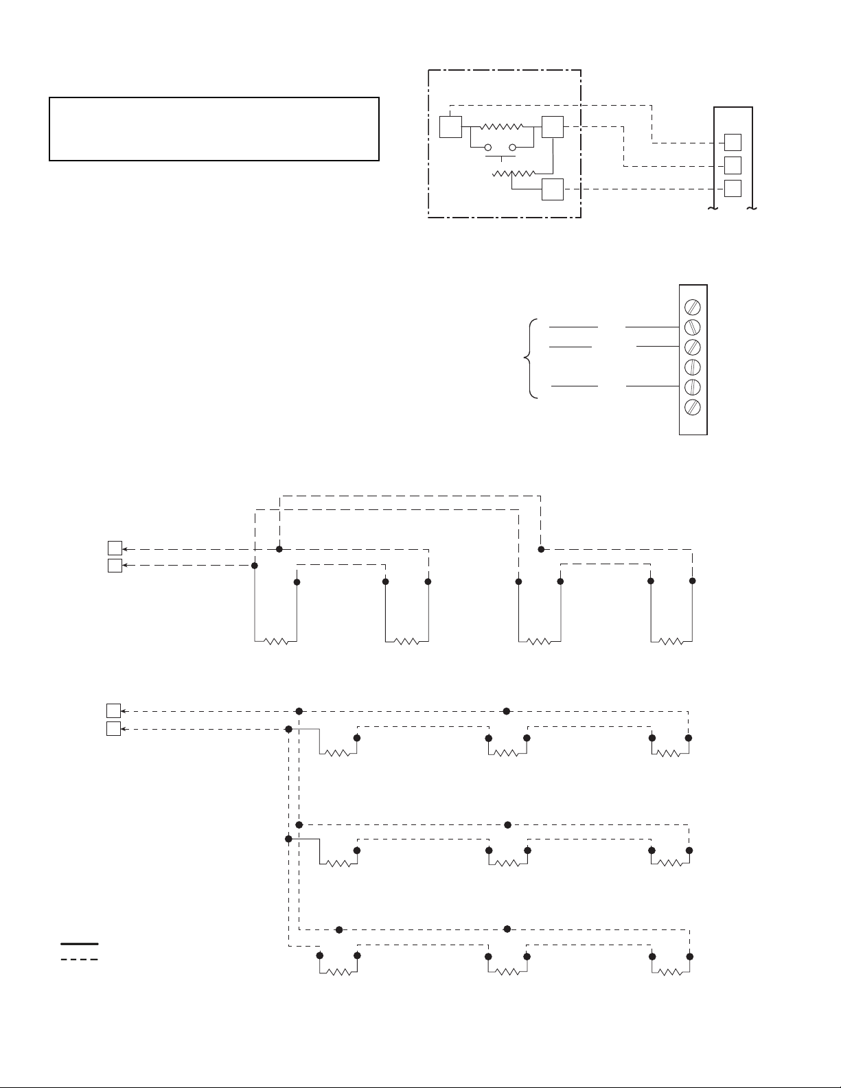
Fig. 26 — CCN Communications Bus Wiring to
Optimal Space Sensor RJ11 Connector
J6
6
7
RED
BLK
RED
RED
BLK
BLK
BLK
RED
BLK
RED
SENSOR 1 SENSOR 2 SENSOR 3 SENSOR 4
J6
6
7
RED
BLK
RED
BLK
SENSOR 2
SENSOR 1
RED
RED
BLK
SENSOR 3
SENSOR 4
BLK
BLK
RED
RED
RED
BLK
BLK
SENSOR 8
SENSOR 9
SENSOR 5
RED
BLK
SENSOR 6
SENSOR 7
BLK
RED
SPACE TEMPERATURE AVERAGING — 4 SENSOR APPLICATION
Fig. 27 — Space Temperature Averaging
LEGEND
Factory Wiring
Field Wiring
SPACE TEMPERATURE AVERAGING — 9 SENSOR APPLICATION
the RJ11 connector provided with the space sensor, if desired.
To wire the RJ11 connector into the CCN (Fig. 26):
IMPORTANT: The cable selected for the RJ11 connector
wiring MUST be identical to the CCN communication bus
wire used for the entire network. Refer to Table 5 for
acceptable wiring.
1. Cut the CCN wire and strip ends of the red (+), white
(ground), and black (–) conductors. (If another wire color
scheme is used, strip ends of appropriate wires.)
2. Insert and secure the red (+) wire to terminal 5 of the
space temperature sensor terminal block.
3. Insert and secure the white (ground) wire to terminal 4 of
the space temperature sensor.
4. Insert and secure the black (–) wire to terminal 2 of the
space temperature sensor.
5. Connect the other end of the communication bus cable to
the remainder of the CCN communication bus.
NOTE: See Fig. 27 for space temperature averaging.
SEN
SPT
SENSOR
SEN
SET
LVT
21
22
23
22
Page 23
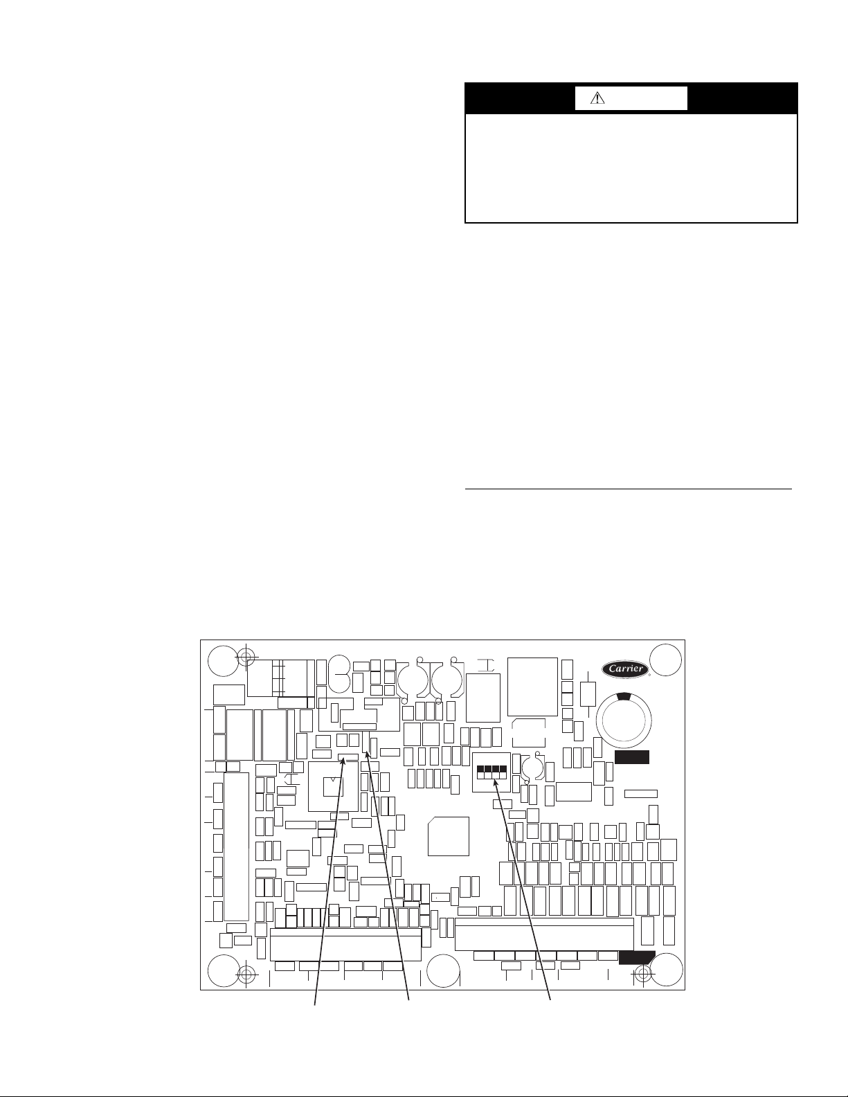
Fan Status Input — A proof-of-fan operation is recom-
CEBD430351-0396-01C
TEST 1
CEPL130351-01
PWR
TEST 2
J1
J2
J4 J3
J5
J6
J7
LEN
STATUS
RED LED - STATUS
GREEN LED LEN (LOCAL EQUIPMENT NETWORK)
ADDRESS
DIP SWITCH
Fig. 28 — Energy Management Module
mended and needs to be field installed in the indoor unit. Several different types of switches can be utilized, such as a differential pressure switch located across the indoor fan or auxiliary
contacts on an indoor fan contactor.
Thermostat Input — A two-stage thermostat can be
used for constant volume applications to provide Y1 and Y2
cooling inputs.
Pressure Transducer Inputs — Each refrigerant cir-
cuit is equipped with a suction and discharge pressure transducer. The suction pressure transducers have a yellow body
with a pressure range of -6.7 to 420 psig while the discharge
transducers have a red body with a pressure range of 14.5 to
667 psig. These inputs connect to the MBB (main base board)
and are used to monitor the status of the unit and to ensure the
unit operates within the compressor envelope. The transducers
are used to protect the compressor from operating at too low or
too high of a pressure condition. In some cases, the unit may
not be able to run at full capacity. The MBB will automatically
reduce the capacity of a circuit as needed to maintain specified
maximum/minimum operating pressures.
Energy Management Module (Fig. 28) — The
energy management module (EMM) is a factory-installed option (FIOP) or field-installed accessory used for the following
types of temperature reset, demand limit, and capacity control
features:
• 4 to 20 mA temperature reset
• 4 to 20 mA cooling set point
• 4 to 20 mA desired capacity set point
• 4 to 20 mA demand limit
• Discrete inputs for 2-step demand limit (requires fieldsupplied dry contacts capable of handling a 24 vac,
50 mA load)
• Discrete inputs for units with dual thermostats
NOTE: A field-supplied 4 to 20 mA signal generator is required for use with the EMM.
See VAV Supply Air Temperature Reset and Demand Limit
sections on pages 29 and 31 for further details.
CAUTION
Care should be taken when interfacing with other manufacturer’s control systems due to possible power supply
differences, full wave bridge versus half wave rectification.
The two different power supplies cannot be mixed.
ComfortLink™ controls use half wave rectification. A
signal isolation device should be utilized if a full wave
bridge signal generating device is used.
Control — When mechanical cooling is required, the MBB
has the capability to control the unit capacity by staging multiple scroll compressors and controlling the digital scroll compressor operation. The control also checks on various other operation parameters in the unit to make sure that safeties are not
exceeded and the compressors are reliably operated.
The ComfortLink™ control system offers two basic control
approaches to mechanical cooling; constant volume operation
for 2 stages of cooling or VAV operation for multiple stages
of cooling. In addition to these methods of control, the
ComfortLink control offers the ability to run multiple stages of
cooling for either a space temperature sensor or thermostat
control by controlling the unit to either a low or high cool set
point. The control type Configuration OPT2 C.TYP determines the selection of the type of cooling control as well as
the method for selecting a cooling mode.
SETTING UP THE SYSTEM
Machine Control Type (
— The most important cooling control configuration is located
under Configuration OPT2. This configuration defines the
method and control source responsible for selecting a cooling
mode. The configuration also determines the method by which
compressors are staged. Control types are:
• C.TYP = 1 (VAV-RAT) configuration refers to standard
VAV operation.
Configuration OPT2 C.TYP)
23
Page 24
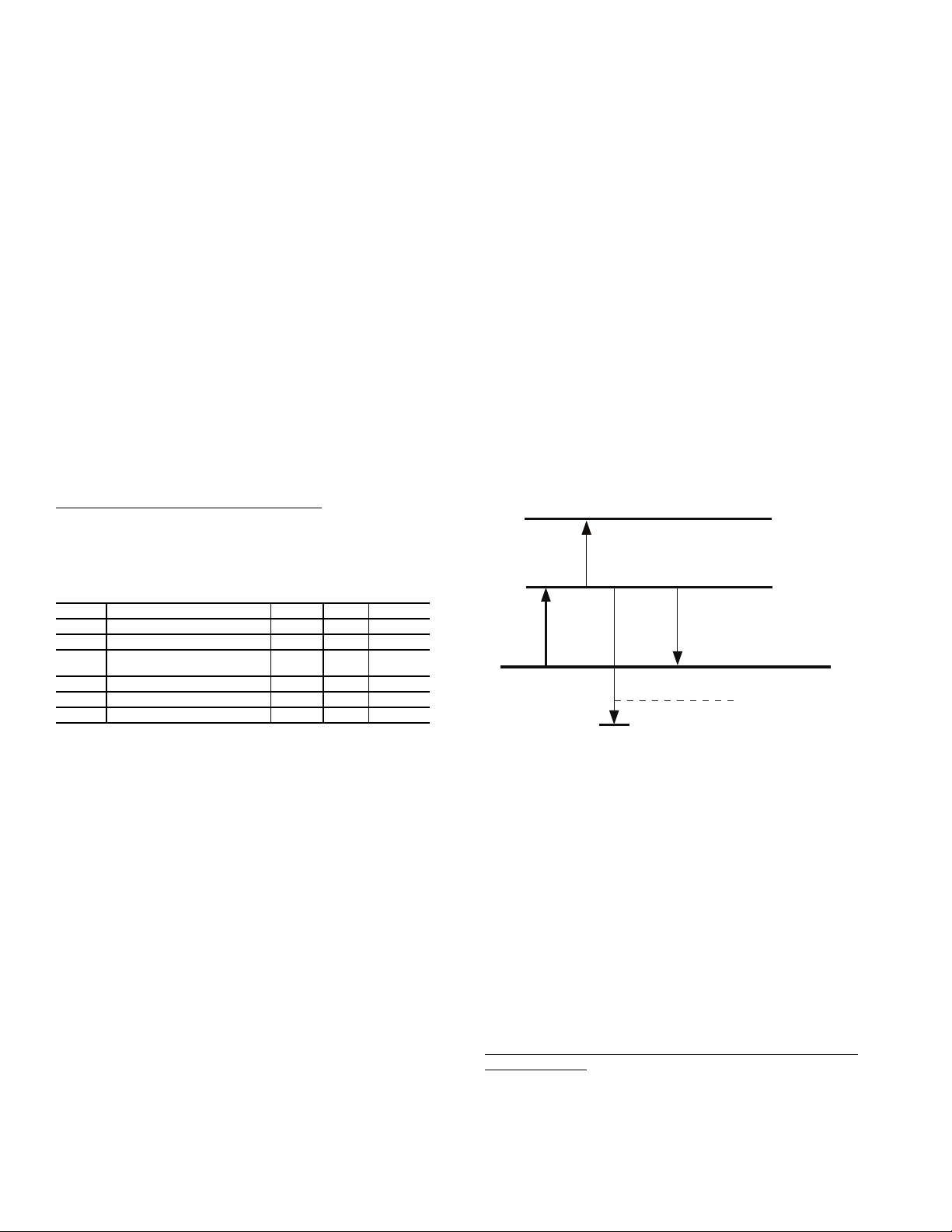
Fig. 29 — Space Temperature vs.
Space Temperature Set Point
A48-7701
• C.TYP = 3 (TSTAT-MULTI) configuration will force
the MBB to monitor the thermostat inputs to make a
determination of mode. Unlike traditional 2-stage thermostat control, the unit is allowed to use multiple stages
of cooling control and perform VAV style operation. The
control will be able to call out a low set point or a high
set point to maintain supply air temperature. (Required
for 025-030 units with digital scroll option and 040-100
units with two-stage thermostat control.)
• C.TYP = 4 (TSTAT-2STG) configuration will force the
MBB to monitor the thermostat inputs to make a determination of mode.
• C.TYP = 5 (SPT-MULTI) configuration will force the
MBB to monitor a space temperature sensor to make a
determination of mode. Unlike traditional 2-stage space
temperature control, the unit is allowed to use multiple
stages of cooling control and perform VAV style operation. The control will be able to call out a low set point or
a high set point to maintain supply air temperature.
• C.TYP = 7 (% CAPACITY) configuration will force the
MBB to monitor the 4-20 cooling demand CL.MA input
and translate this into desired % capacity for the unit.
• C.TYP = 9 (VAV-SETPOINT) configuration will force
the MBB to monitor the 4-20 cooling demand CL.MA
input. This value will be translated into a desired leaving-air set point ranging from 40 to 80 F. The control will
translate the input linearly with 4 ma equal to 40 F set
point and 20 mA equal to 80 F set point.
Unit Capacity Control Based on Unit Type
— The MBB
uses several set points to control capacity depending on unit
type. The set points are located in the set point area of the display SetPoints COOL. Refer to Table 6 and the following
descriptions.
Table 6 — Unit Capacity Control
ITEM DESCRIPTION RANGE UNITS DEFAULT
CSP1 Cooling Set Point 1 40-80 F 65
CSP2 Cooling Set Point 2 40-80 F 55
SPS.P Space Temperature Cooling Set
Poin t
L.C.ON Demand Level Low Cool On –1-2 ^F 1.5
H.C.ON Demand Level (+) High Cool On 0.5-20.0 ^F 0.5
L.C.OF Demand Level (–) Low Cool Off 0.5-2 ^F 1
65-80 F 74
• C.TYP = 1 (VAV-RAT) is a capacity control routine that
controls compressor capacity to supply air temperature.
The MBB will attempt to control leaving temperature to
the control point (CTPT) which equals CSP1 plus any
reset which is being applied.
• C.TYP = 3 (TSTAT-MULTI) configuration will force the
MBB to monitor the thermostat inputs to make a determination of control point (CTPT). The control will vary
the control point based on Y1 and Y2 inputs. When Y1 is
closed CSP1 will be used and when Y2 is closed CSP2
will be used as the supply air temperature set point.
CSP1 should be greater than CSP2.
• C.TYP = 4 (TSTAT-2STG) configuration will force the
MBB to monitor the thermostat inputs to make a determination of mode and capacity. If Y1 input is closed,
50% of the unit capacity will be energized and if Y2 is
closed, 100% of the unit capacity will be energized.
NOTE: This is not a preferred method of control for units
with greater than 2 stages of capacity
• C.TYP = 5 (SPT-MULTI) configuration will force the
MBB to monitor the thermostat inputs to determine
mode and cooling set point as the unit is controlled by
space temperature vs space temperature set point SPS.P.
Unlike traditional 2-stage thermostat control, the unit is
allowed to use multiple stages of cooling control and perform VAV style operation. The control will be able to call
out a low set point (CSP1) or high set point (CSP2) for
supply air depending on space temperature vs space
temperature set point. The control uses SPS.P, LC.ON,
HC.ON, and LC.OF to determine the leaving set point.
LC.ON and HC.ON are added to the space temperature
set point to determine when cooling mode will begin and
when CSP1 and CSP2 will be used for leaving set point.
Based on LC.OF, the control point transitions between
CSP1 and CSP2. LC.OF is used to calculate the space temperature at which control point is raised based on space temperature vs space temperature set point (SPS.P) plus
LC.ON minus LC.OF. The control point transition from
CSP2 to CSP1 occurs when space temperature is below
LC.OF divided by 2.
For example (see Fig. 29):
Given: SPS.P = 72 F, LC.ON = 1, HC.ON = 3,
LC.OF = 2 F, CSP1 = 60 F, and CSP2 = 55 F
If space temperature equals 73 F (72+1) (Low Cool)
cooling will begin and control set point equals 60 F
(CSP1).
If space temperature is greater than 76 F (72+1+3 = 76)
(High Cool), control point set point would equal 55 F
(CSP2).
If space temperature falls below 72 F (73-2/2) (Low
Cool minus LC.OF/2), control point transitions back to
60 F CSP1 if space continues to fall below 71 F (73-2)
(Low Cool minus LC.OF), the unit is shut off.
76 F
H.C.ON
73 F
L.C.ON
L.C. OF
Cooling Setpoint
L.C. OF/2
Hi Cool End 72 F72 F
Lo Cool End 71 F
• C.TYP = 7 (% CAPACITY) configuration will force the
MBB to monitor the input 4-20 cooling demand CL.MA
and translate this into desired % capacity for the unit.
The control will attempt to match the desired capacity
insuring the unit operates the compressor within compressor safeties and timeguards. (Requires the EMM
option or accessory.)
• C.TYP = 9 (VAV-SETPOINT) configuration will force
the MBB to operate as a VAV unit and control capacity to
meet supply air temperature. The control point is developed from the 4-20 cooling demand CL.MA input value.
The 4 to 20 mA input will be translated into a desired
control point ranging from 40 to 80 F. The control will
translate the input linearly with 4 mA equal to 40 F set
point and 20 mA equal to 80 F set point. (Requires the
EMM option or accessory.)
Capacity Control Logic when Control is Controlling to Supply Temperature — The control system cycles compressors,
hot gas bypass and the digital compressor to maintain the supply temperature at or close to the control point of the unit. The
SAT and RAT sensors are used by the main base board (MBB)
to determine the temperature drop across the evaporator and
are used in determining the optimum time to add or subtract capacity stages. The CSP set points can be automatically reset by
24
Hi Cool Start
Lo Cool Start
Page 25
the return temperature, space, or outdoor-air temperature reset
features. It can also be reset from an external 4 to 20 mA signal
(requires energy management module factory-installed option
or field-installed accessory).
The control has an automatic lead-lag feature built in which
determines the wear factor (combination of starts and run
hours) for each compressor. If all compressors are off and less
than 30 minutes has elapsed since the last compressor was
turned off, the wear factor is used to determine which compressor to start next. As additional stages of compression are required, the processor control will add them. If a circuit is to be
stopped, the compressor with the lowest wear factor will be
The capacity control algorithm runs every 30 seconds. The
algorithm attempts to maintain the control point at the desired
set point. Each time it runs, the control reads the entering and
leaving temperatures. The control determines the rate at which
conditions are changing and calculates 2 variables based on
these conditions. Next, a capacity ratio is calculated using the
2 variables to determine whether or not to make any changes to
the current stages of capacity. This ratio value ranges from
–100 to +100%. If the next stage of capacity is a compressor,
the control starts (stops) a compressor when the ratio reaches
+100% (-100%). A delay of 90 seconds occurs after each capacity step change. Refer to Table 8.
shut off first. See Table 7 for compressor size information and
Table 8 for compressor loading sequence.
Table 7 — Compressor Size Information
UNIT SIZE
38APS025 11 11 — — — —
38APD025 11 — — 11 — —
38APS027 13 13 — — — —
38APD027 13 — — 13 — —
38APS030 15 15 — — — —
38APD030 15 — — 15 — —
38APS040 13 13 13 — — —
38APD040 10 10 — 9 9 —
38APS050 15 15 15 — — —
38APD050 12 12 — 13 13 —
38APD060 13 13 — 15 15 —
38APD070 15 15 — 11 11 11
38APD080 15 15 — 15 15 15
38APD090 13 13 13 15 15 15
38APD100 15 15 15 15 15 15
Compressor A1 Compressor A2 Compressor A3 Compressor B1 Compressor B2 Compressor B3
CIRCUIT A (Nominal hp) CIRCUIT B (Nominal hp)
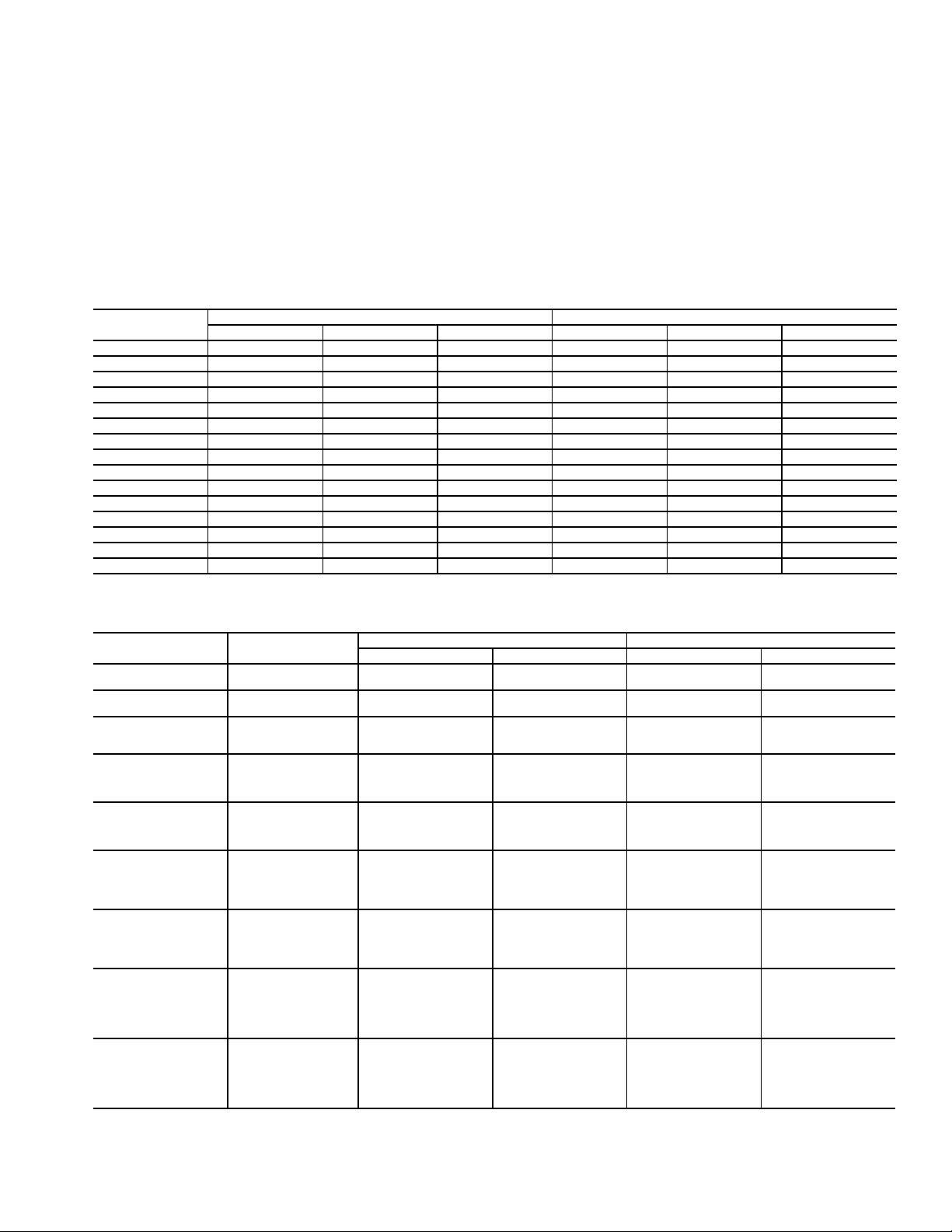
Table 8 — Part Load Data Percent
38AP UNIT SIZE
38APS025-030
38APD025-030
38APS040,050
38APD040
38APD050,060
38APD070
38APD080
38APD090
38APD100
NOTES:
1. These capacity steps may vary due to different capacity staging
sequences.
CONTROL
STEPS
150A1——
2 100 A1,A2 — —
1 50A150B1
2 100 A1, B1 100 A1,B1
133A1——
267A1,A2——
3 100 A1,A2,A3 — —
127A123B1
2 50 A1,B1 50 A1,B1
3 77A1,A2,B1 73A1,B1,B2
4 100 A1,A2,B1,B2 100 A1,A2,B1,B2
123A127B1
2 50 A1,B1 50 A1,B1
3 73A1,A2,B1 77A1,B1,B2
4 100 A1,A2,B1,B2 100 A1,A2,B1,B2
1 15A115B1
2 42 A1,B1 42 A1,B1
3 57A1,A2,B157A1,B1,B2
4 85 A1,A2,B1,B2 85 A1,A2,B1,B2
5 100 A1,A2,B1,B2,B3 100 A1,A2,B1,B2,B3
1 20A120B1
2 40 A1,B1 40 A1,B1
3 60A1,A2,B160A1,B1,B2
4 80 A1,A2,B1,B2 80 A1,A2,B1,B2
5 100 A1,A2,B1,B2,B3 100 A1,A2,B1,B2,B3
1 15A118B1
2 32 A1,B1 32 A1,B1
3 48A1,A2,B151A1,B1,B2
4 66 A1,A2,B1,B2 66 A1,A2,B1,B2
5 82 A1,A2,A3,B1,B2,B3 85 A1,A2,B1,B2,B3
6 100 A1,A2,A3,B1,B2,B3 100 A1,A2,A3,B1,B2,B3
1 17A117B1
2 33 A1,B1 33 A1,B1
3 50A1,A2,B150A1,B1,B2
4 67 A1,A2,B1,B2 67 A1,A2,B1,B2
5 83A1,A2,A3,B1,B283A1,A2,B1,B2,B3
6 100 A1,A2,A3,B1,B2,B3 100 A1,A2,A3,B1,B2,B3
% Displacement Compressor % Displacement Compressor
LOADING SEQUENCE A LOADING SEQUENCE B
2. When unit is equiped with digital scroll option, sequence A is always
used.
25
Page 26
MINUTES LEFT FOR START — This value is displayed
only in the network display tables (using Service Tool,
ComfortVIEW™ or ComfortWORKS
®
software) and
represents the amount of time to elapse before the unit will start
its initialization routine. This value can be zero without the
machine running in many situations. This can include being
unoccupied, ENABLE/OFF/REMOTE CONTACT switch in
the OFF position, CCN not allowing unit to start, Demand
Limit in effect, no call for cooling due to no load, and alarm or
alert conditions present. If the machine should be running and
none of the above are true, a minimum off time (DELY, see
below) may be in effect. The machine should start normally
once the time limit has expired.
MINUTES OFF TIME (Configuration OPT2
DELY) — This user-configurable time period is used by
the control to determine how long unit operation is delayed
after power is applied/restored to the unit. Typically, this time
period is configured when multiple machines are located on a
single site. For example, this gives the user the ability to prevent all the units from restarting at once after a power failure.
A value of zero for this variable does not mean that the unit
should be running.
NOTE: If the unit has digital scroll or hot gas bypass, circuit A
is always lead.
LEAD/LAG DETERMINATION — This is a configurable
choice and is factory set to be automatic for all units. The value
can be changed to Circuit A or Circuit B leading as desired. Set
at automatic, the control will sum the current number of logged
circuit starts and one-quarter of the current operating hours for
each circuit. The circuit with the lowest sum is started first.
Changes to which circuit is the lead circuit and which is the lag
are also made when total machine capacity is at 100% or when
there is a change in the direction of capacity (increase or
decrease) and each circuit’s capacity is equal.
CAPACITY CONTROL OVERRIDES — The following overrides will modify the normal operation of the routine.
Deadband Multiplier
— The user configurable deadband mul-
tiplier (Configuration SLCT Z.GN) has a default value of
1.0. The range is from 1.0 to 4.0. When set to other than 1.0,
this factor is applied to the capacity Load/Unload Factor. The
larger this value is set, the longer the control will delay between
adding or removing stages of capacity.
First Stage Override
— If the current capacity stage is zero,
the control will modify the routine with a 1.2 factor on adding
the first stage to reduce cycling. This factor is also applied
when the control is attempting to remove the last stage of
capacity.
Slow Change Override
— This control prevents the capacity
stages from being changed when the supply temperature is
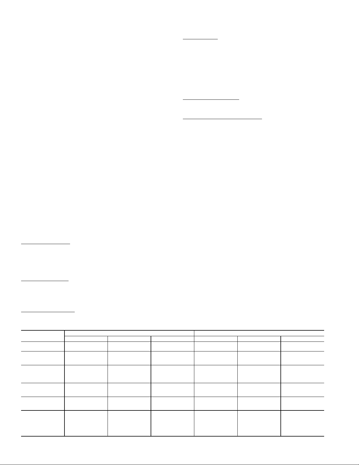
Table 9 — Fan Stages
38AP UNIT SIZE
025-030
040,050
060
070
080
090,100
* Fan Stage 1 on unit size 070 is used only when ambient temperature is less than 32 F.
CIRCUIT A STAGES/COMMON FAN STAGES CIRCUIT B FAN STAGES
Fan Stage Contactor Energized Fans Operating Fan Stage Contactor Energized Fans Operating
Stage 1
Stage 2
Stage 1
Stage 2
Stage 3
Stage 1
Stage 2
Stage 3
Stage 4
Stage 1*
Stage 2
Stage 3
Stage 1
Stage 2
Stage 1
Stage 2
Stage 3
Stage 4
Stage 5
Stage 6
FC1
FC1,2
FC1
FC2
FC1,2
FC1
FC2
FC1,2
FC1,2,3
FC2,4
FC1
FC1,3
FC1
FC1,3
FC4
FC1
FC4,1
FC4,3
FC1,3
FC4,1,3
OFM1
OFM1,2
OFM3
OFM1,2
OFM1,2,3
OFM3
OFM1,2
OFM1,2,3
OFM1,2,3,4
OFM1,2
OFM3
OFM3,4
OFM5
OFM5,6,(2)
OFM3
OFM5
OFM3,5
OFM3,(2),4,6
OFM5,(2),4,6
OFM3,5,(2),4,6
close to the set point (within an adjustable deadband) and moving toward the set point.
Ramp Loading
— The ramp loading control (Configuration
SLCT CRMP) limits the rate of change of supply temperature. If the unit is in a Cooling mode and configured for Ramp
Loading, the control makes 2 comparisons before deciding to
change stages of capacity. The control calculates a temperature
difference between the control point and supply temperature. If
the difference is greater than 4° F (2.2° C) and the rate of
change (°F or °C per minute) is more than the configured Cooling Ramp Loading value (CRMP), the control does not allow
any changes to the current stage of capacity.
Minimum Load Control
— If equipped, the minimum load
control valve is energized only when one compressor on the
circuit is running and the unit is unloading.
Low Saturated Suction Protection
— The control will try to
prevent shutting a circuit down due to low saturated suction
conditions by removing stages of capacity. See Alerts section.
Head Pressure Control — The main base board
(MBB) controls the condenser fans to maintain the lowest
condensing temperature possible, and thus the highest unit
efficiency. The MBB uses the saturated condensing temperature input from the discharge pressure transducer and outside
air temperature sensor to control the fans. If OAT is greater
than 70 F before a circuit is starting, then all condenser fan
stages will be energized. A fan stage is increased based on
SCT. When the highest SCT of both circuits is greater than fan
on set point, then an additional stage of fan will be added to the
current fan stage. Fan On Set Point (F. O N ) equals Head Set
Point ON (115 F) except after a fan stage increase when Head
Set Point is increased by Fan Stage Delta (10 F). A fan stage is
decreased when the SCTs of both circuits are less than fan off
set point for two minutes. Fan Off Set Point (F. O F F ) equals
Head Set Point OFF (–72 F). Table 9 shows the number of fan
stages, contactors energized and the fans that are on during the
fan stage. Unit sizes 025 to 060 have common fan control. Unit
sizes 070 to 100 have some fans that are common and some
that are controlled individually. Figure 30 shows the location
of each fan and compressor within the unit.
MOTORMASTER
tion, the first stage of fans is equipped with the Motormaster V
head pressure controller option or accessory. For units with
common fans, the control will control the Head Pressure Setpoint (–10 F) and the highest SCT to try to maintain it at 100 F.
Unit sizes 070 to 100 have one Motormaster V for each circuit
and the control tries to maintain SCT at 100 F for the circuit.
The controller is given an ON command with the first stage of
fan and adjusts fan speed.
Stage 1*
Stage 2
Stage 3
Stage 1
Stage 2
Stage 3
Stage 1
Stage 2
Stage 3
Stage 4
Stage 5
Stage 6
®
V OPTION — For low-ambient opera-
———
———
———
FC1,3
FC2
FC2,4
FC4
FC3,4
FC2,3,4
FC4
FC2
FC4,2
FC4,3
FC2,3
FC4,2,3
OFM3,4
OFM1
OFM1,2
OFM3
OFM3,2,(6)
OFM3,1,2,(6)
OFM3
OFM1
OFM3,1
OFM3,2,4,(6)
OFM1,2,4,(6)
OFM3,1,2,4,(6)
26
Page 27
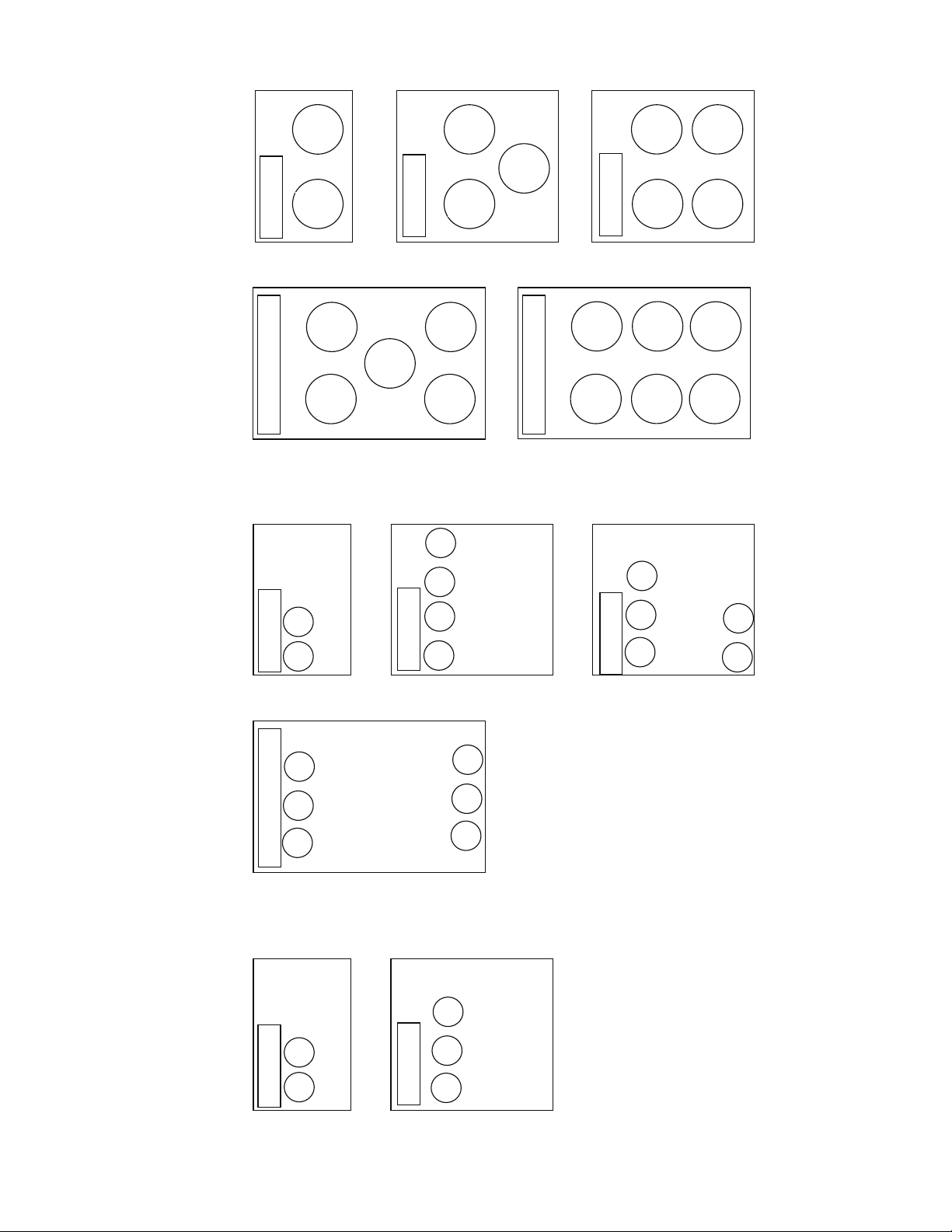
Outdoor Fan Layout – Top View
Sizes 025-030 Sizes 040, 050 Sizes 060, 070
CONTROL BOX
CONTROL BOX
OFM1
OFM2 OFM2
OFM3
OFM1
CONTROL BOX
OFM3
OFM4
OFM2
OFM1
Size 080 Sizes 090, 100
CONTROL BOX
OFM2
OFM3
OFM5
OFM6
OFM1
CONTROL BOX
OFM4
OFM5
OFM6
OFM2
OFM3
OFM1
Compressor Layout Dual Circuit – Top View
Sizes 025-030 Sizes 040-060 Sizes 070, 080
CONTROL BOX
1
B1
CONTROL BOX
B1
B2
1
2
CONTROL BOX
B1
B2
2
1
B3
Sizes 090, 100
CONTROL BOX
B1
B2
B3
3
2
1
Sizes 025-030 Sizes 040, 050
CONTROL BOX
CONTROL BOX
Compressor Layout Single Circuit – Top View
1
2
1
2
3
Fig. 30 — Compressor and Fan Location
A
A
A
A
A
A
A
A
A
A
A
A
A
27
Page 28

Service Test — Both main power and control circuit
ENTER
ENTER
ESCAPE
power must be on.
The Service Test function should be used to verify proper
operation of condenser fan(s), compressors, minimum load
valve solenoid (if installed), liquid line solenoid valve (if
installed), and remote alarm relay. To use the Service Test
mode, the Enable/Off/Remote Contact switch must be in the
OFF position. Use the display keys and Service Test Mode and
Sub-Mode Directory table in Appendix A to enter the mode
and display TEST. Press twice so that OFF flashes.
Enter the password if required. Use either arrow key to change
the TEST value to the ON position and press . Place
the Enable/Off/Remote Contact switch in the ENABLE position. The Service Test mode is now enabled. Press
and the down key to enter the OUTS, COMPA or COMPB
sub-mode.
Test the condenser fans, liquid line solenoid and alarm relay by changing the item values from OFF to ON. These discrete outputs are then turned off if there is no keypad activity
for 10 minutes. When testing the digital output the display can
be changed from 1 to 15 by using either the up or down arrow;
the number represents the cycle rate out of a 15 second duty cycle that the output will be energized. If the cycle is set for 7, the
output will be energized 7 seconds out of every 15 seconds.
Test the compressor and minimum load valve solenoid (if installed) outputs in a similar manner. The minimum load valve
solenoids will be turned off if there is no keypad activity for
10 minutes. Compressors will stay on until they are turned off
by the operator. The Service Test mode will remain enabled for
as long as there is one or more compressors running. All safeties are monitored during this test and they will turn a compressor, circuit or the machine off if required. Any other mode or
sub-mode can be accessed, viewed, or changed during the
TEST mode. The STAT item (Run/Status VIEW) will display "0" as long as the Service mode is enabled. The TEST
sub-mode value must be changed back to OFF before the unit
can be switched to Enable or Remote contact for normal
operation.
Operating Modes
RAMP LOAD LIMITED (MD05) — Ramp load (pulldown) limiting is in effect. In this mode, the rate at which supply fluid temperature is dropped is limited to a predetermined
value to prevent compressor overloading. See Cooling Ramp
Loading (Configuration SLCT CRMP). The pull-down
limit can be modified, if desired, to any rate from 0.2 to 2° F
(0.1 to 1° C) per minute.
TIMED OVERRIDE IN EFFECT (MD06) — Timed override is in effect. This is a 1 to 4 hour temporary override of the
programmed schedule, forcing unit to Occupied mode. Override can be implemented with unit under Local (Enable) or
CCN (Carrier Comfort Network
ter each use.
SLOW CHANGE OVERRIDE (MD09) — Slow change
override is in effect. The supply fluid temperature is close to
and moving towards the control point.
MINIMUM OFF TIME ACTIVE (MD10) — Unit is being
held off by Minutes Off Time (Configuration
OPT2 DELY).
TEMPERATURE RESET (MD14) — Temperature reset is
in effect. In this mode, unit is using temperature reset to adjust
supply fluid set point upward and is currently controlling to the
modified set point. The set point can be modified based on return fluid, outdoor-air-temperature, space temperature, or 4 to
20 mA signal.
DEMAND LIMITED (MD15) — Demand limit is in effect.
This indicates that the capacity of the unit is being limited by
®
) control. Override expires af-
demand limit control option. Because of this limitation, the unit
may not be able to produce the desired supply fluid temperature. Demand limit can be controlled by switch inputs or a 4 to
20 mA signal.
LOW TEMPERATURE COOLING (MD17) — Unit is in
Cooling mode and the rate of change of the supply fluid is negative and decreasing faster than -0.5° F per minute. Error between supply fluid and control point exceeds fixed amount.
Control will automatically unload the unit if necessary.
HIGH TEMPERATURE COOLING (MD18) — Unit is in
Cooling mode and the rate of change of the supply fluid is positive and increasing. Error between supply fluid and control
point exceeds fixed amount. Control will automatically load
the unit if necessary to better match the increasing load.
TIME GUARD ACTIVE (MDTG) — Compressor time
guard is active, preventing the compressor from starting.
HIGH SCT CIRCUIT A (MD21) — Unit is in a Cooling
mode and the saturated condensing temperature (SCT) is greater than the calculated maximum limit. No additional stages of
capacity will be added. Unit capacity may be reduced if SCT
continues to rise to avoid high-pressure switch trips by reducing condensing temperature.
HIGH SCT CIRCUIT B (MD22) — Unit is in a Cooling
mode and the saturated condensing temperature (SCT) is greater than the calculated maximum limit. No additional stages of
capacity will be added. Unit capacity may be reduced if SCT
continues to rise to avoid high-pressure switch trips by reducing condensing temperature.
MINIMUM COMP ON TIME (MD23) — Cooling load
may be satisfied, however control continues to operate compressor to ensure proper oil return. This may be an indication of
oversized application, low fluid flow rate or low loop volume.
LOW SOUND MODE (MD25) — Not applicable.
Operation of Machine Based on Control
Method —
the configuration of the control method
(Configuration OPT2 CTRL). With the control method
set to 0, simply switching the Enable/Off/Remote Contact
switch to the Enable or Remote Contact position (external contacts closed) will put the unit in an occupied state. The control
mode (Operating Modes MODE) will be 1 (OFF LOCAL)
when the switch is Off and will be 5 (ON LOCAL) when in the
Enable position or Remote Contact position with external contacts closed.
Two other control methods are available for Machine On/
Off control:
OCCUPANCY SCHEDULE (CTRL=2) — The main base
board will use the operating schedules as defined under the
Time Clock mode in the scrolling marquee display. These
schedules are identical. The schedule number must be set to 1
for local schedule.
The schedule number can be set anywhere from 65 to 99
for operation under a CCN global schedule. The Enable/Off/
Remote Contact must be in the Enable or Remote Contact position. The control mode (Operating Modes MODE) will be 1
when the switch is Off. The control mode will be 3 when the
Enable/Off/Remote Contact switch input is On and the time of
day is during an unoccupied period. Similarly, the control
mode will be 7 when the time of day is during an occupied
period.
CCN SCHEDULE (CTRL=3) — An external CCN device
controls the On/Off state of the machine. This CCN device
forces the variable 'CHIL_S_S' between Start/Stop to control
the unit. The control mode (Operating Modes MODE) will
be 1 when the switch is Off. The control mode will be 2 when
the Enable/Off/Remote Contact switch input is On and the
Machine On/Off control is determined by
28
Page 29

CHIL_S_S variable is 'Stop.' Similarly, the control mode will
64
62
60
58
56
54
52
17.8
16.7
15.6
14.4
13.3
12.2
11.1
40 45 50 55 60 65 70 75 80 85 90
4.4 7.2 10.0 12.8 15.6 18.3 21.1 23.9 26.7 29.4 32.2
OUTSIDE TEMPERATURE (F)
OUTSIDE TEMPERATURE (C)
SAT TEMPERATURE (F)
MAXIMUM RESET
RESET SET POINT
CHILLED SET POINT
CHANGE
IN SAT
SET POINT
CHANGE IN
RESET TEMPERATURE
SAT
SAT TEMPERATURE (C)
LEGEND
Fig. 31 — Outdoor-Air Temperature Reset
SAT — Supply Air Temperature
LEGEND
Fig. 32 — Space Temperature Reset
SAT — Supply Air Temperature
be 6 when the CHIL_S_S variable is 'Start.'
Set Point Adjustment
CV SET POINT ADJUSTMENT — If the unit is configured
for control type SPT MULTI (C.TYP =5) and the Space Temperature Offset Sensor is enabled. (SP.O.S) set to enable
[Configuration OPT1]. Space temperature offset corresponds to a slider on a T56 sensor that allows the occupant to
adjust the space temperature by a configured range during an
occupied period. The space temperature offset range (SP.O.R)
value is either added or subtracted from the space temperature
cool set point. Example SPS.P equals 72 F and SP.O.R equals
5 then the cooling set point can be adjusted from 68 to 77 F by
adjusting the T56 slider.
ITEM EXPANSION RANGE UNITS CCN POINT
SP.O.S
SP.O.R
Space Temp
Offset Sensor
Space Temp
Offset Range
VAV SUPPLY AIR TEMPERATURE RESET — The control system is capable of changing the controlling set point
based on several different methods. The methods are return
temperature, space temperature (SPT), outside air temperature
(OAT) and from an externally powered 4 to 20 mA signal. Return air is a measure of the building load. The return temperature reset is in effect an average building load reset method. An
accessory sensor must be used for SPT reset; either a T55, T56,
or T59 sensor can be used. The energy management module
(EMM) must be used for temperature reset using a 4 to 20 mA
signal. To use 4 to 20 mA reset, one variable must be configured MA.DG, which is the amount of reset desired with a
20 mA signal. The control will interpolate between 0 degrees
reset at 4 mA and the value entered for MA.DG at 20 mA. See
Table 10 for an example of 4 to 20 mA reset.
Enable/
Disable
1-10 SPTO_RNG
SPTOSENS
be set to the temperature difference where the maximum reset
should occur. The variable RM.DG
should be set to the
maximum amount of reset desired. To verify that reset is functioning correctly proceed to Run Status mode, sub-mode
VIEW, and subtract the active set point (SETP) from the con-
trol point (CTPT) to determine the degrees reset. Under normal
operation, the unit will maintain a constant leaving temperature
approximately equal to the cooling set point. As the unit load
varies, the return air temperature will change in proportion to
the load. Usually the unit size and supply air temperature set
point are selected based on a full-load condition. At part load,
the air temperature set point may be colder than required. If the
leaving air temperature was allowed to increase at part load, the
efficiency of the machine would increase.
Return temperature reset allows for the leaving temperature
set point to be reset upward as a function of the return air temperature or, in effect, the building load.
Figures 31 and 32 are examples of outdoor air and space
temperature reset.
CAUTION
Care should be taken when interfacing with other control
systems due to possible power supply differences; full
wave bridge versus half wave rectification. Connection of
control devices with different power supplies may result in
permanent equipment damage. ComfortLink™ controls
incorporate power supplies with half wave rectification. A
signal isolation device should be utilized if the signal generator incorporates a full wave bridge rectifier.
To use Outdoor Air or Space Temperature reset, four variables must be configured. In the Configuration mode under the
sub-mode RSET, items CRST, RM.NO, RM.F and RT.DG
must be properly set. See Table 11. The outdoor air reset example provides 0° F (0° C) reset to the active set point at 85 F
(29.4 C) outdoor-air temperature and 6 F (3.3 C) reset at 55 F
(12.8 C) outdoor-air temperature. See Fig 31. The space temperature reset example provides 0° F (0° C) reset to the active
set point at 72 F (22.2 C) space temperature and 6 F (3.3 C) reset at 68 F (20.0 C) space temperature. See Fig 32. The variable
CRST should be configured for the type of reset desired. The
variable RM.NO should be set to the temperature that no reset
should occur. The variable RM.F should be set to the tempera-
ture that maximum reset is to occur. The variable RM.DG
should be set to the maximum amount of reset desired.
To use Return reset, four variables must be configured. In
the Configuration mode under the sub-mode RSET, items
CRST, RT.NO, RT.F and RT.DG must be properly set. See
Table 12.
This example provides 5 F (2.8 C) active set point reset at
2 F (1.1 C) T and 0° F (0° C) reset at 10 F (5.6 C) T. The
variable RT.NO should be set to the air temperature difference
( T) where no reset should occur. The variable RT.F should
29
SAT TEMPERATURE (C)
17.8
16.7
15.6
14.4
13.3
12.2
11.1
64
62
60
58
MAXIMUM RESET
56
SAT TEMPERATURE (F)
54
52
65 66 67 68 69 70 71 72 73 74
18.3 18.9 19.4 20.0 20.6 21.1 21.7 22.2 22.8 23.3
SPACE TEMPERATURE (F)
SPACE TEMPERATURE (C)
CHANGE IN
RESET TEMPERATURE
SAT
RESET SET POINTCHILLED SET POINT
CHANGE
IN SAT
SET POINT
Page 30

Table 10 — 4 to 20 mA Reset
ENTER
ENTER
ENTER
ENTER
ENTER
SUB-MODE
KEYPAD
ENTRY
ITEM DISPLAY
RSET
CRST 1
MA.DG
5.0 F
(2.8 C)
NOTE: The example above shows how to configure the unit for 4 to
20 mA reset. No reset will occur at 4.0 mA input, and a 5.0 F reset
will occur at 20.0 mA. An energy management module is required.
Table 11 — Configuring Outdoor Air and Space Temperature Reset
MODE
(RED LED)
CONFIGURATION
*1 item skipped in this example.
KEYPAD
ENTRY
SUB-
MODE
KEYPAD
ENTRY
ITEM
DISP
UNIT
OPT1
OPT2
M.MST
RSET CRST 2 4
RM.NO* 85 °F 72 °F
RM.F 55 °F 68 °F
RM.DG 15 °F 6 °F
ITEM
EXPANSION
COOLING RESET
TYPE
4-20 mA DEGREES RESET
DISPLAY
Outdoor
Air
Space
COOLING RESET
REMOTE - FULL
REMOTE - DEGREES
COMMENT
0 = no reset
1 = 4 to 20 mA Input
2 = Outdoor Air Temp
3 = Return Fluid
4 = Space Temperature
Default: 0° F (0° C) Reset at 20 mA
Range: –30 to 30 F (–16.7 to 16.7 C)
ITEM
EXPANSION
2 = Outdoor-Air Temperature
TYPE
REMOTE - NO
RESET TEMP
RESET TEMP
RESET
4 = Space Temperature
(Connect to LTV-21,22)
Default: 125.0 F (51.7 C)
Range: 0° to125 F
Default: 0.0° F (-17.7 C)
Range: 0° to 125 F
Default: 0° F (0° C)
Range: –30 to 30 F
(–34.4 to -1.1 °C)
COMMENT
(-17.7 to 51.7 C)
(-17.7 to 51.7 C)
MODE
(RED LED)
KEYPAD
ENTRY
CONFIGURATION
*4 items skipped in this example.
Table 12 — Configuring Return Temperature Reset
SUB-MODE
KEYPAD
ENTRY
ITEM DISPLAY
DISP
UNIT
CNN
OPT1
OPT2
M.MST
RSET CRST* 3
RT.NO* 10°
RT.F 0°
RT.DG 5° F
F
F
RETURN - DEGREES
ITEM
EXPANSION
COOLING
RESET TYPE
RETURN - NO
RESET TEMP
RETURN - FULL
RESET TEMP
RESET
COMMENT
0 = No Reset
1 = 4 to 20 mA Input (EMM required)
2 = Outdoor-Air Temperature
3 = Return Air Temperature
4 = Space Temperature
Default: 10°
Range: 0° to 30 F
Default: 0°
Range: 0° to 10 F T (-17.7 to –12.2 C)
Default: 0°
Range: –30 to 30°F (–16.7 to 16.7 C)
F (5.6° C)
T (-17.7 to 16.7 C)
F (–17.8° C)
F (0° C)
30
Page 31

Demand Limit — Demand Limit is a feature that allows
ENTER
ENTER
the unit capacity to be limited during periods of peak energy
usage. There are 3 types of demand limiting that can be
configured. The first type is through 2-stage switch control,
which will reduce the maximum capacity to 2 user-configurable percentages. The second type is by 4 to 20 mA signal input which will reduce the maximum capacity linearly between
100% at a 4 mA input signal (no reduction) down to the userconfigurable level at a 20 mA input signal. The third type uses
the CCN loadshed module and has the ability to limit the current operating capacity to maximum and further reduce the capacity if required.
NOTE: The 2-stage switch control and 4 to 20 mA input signal
types of demand limiting require the energy management
module (EMM).
To use Demand Limit, select the type of demand limiting to
use. Then configure the Demand Limit set points based on the
type selected.
DEMAND LIMIT (2-Stage Switch Controlled) — To configure Demand Limit for 2-stage switch control, set the Demand
Limit Select (Configuration RSET DMDC) to 1. Then
configure the 2 Demand Limit Switch points
(Configuration RSET DLS1 and DLS2) to the desired capacity limit. See Table 13. Capacity steps are controlled by 2 relay switch inputs field wired to low voltage terminal (LVT) strip
terminal 3-6. Refer to the unit wiring diagram for these connections.
For Demand Limit by 2-stage switch control, closing the
first stage demand limit contact will put the unit on the first demand limit level. The unit will not exceed the percentage of capacity entered as Demand Limit Switch 1 set point. Closing
contacts on the second demand limit switch prevents the unit
Table 13 — Configuring Demand Limit
MODE
CONFIGURATION
KEYPAD
ENTRY
SUB-MODE
DISP
UNIT
KEYPAD
ENTRY
ITEM DISPLAY ITEM EXPANSION COMMENT
from exceeding the capacity entered as Demand Limit Switch
2 set point. The demand limit stage that is set to the lowest
demand takes priority if both demand limit inputs are closed. If
the demand limit percentage does not match unit staging, the
unit will limit capacity to the closest capacity stage.
To disable demand limit, configure the DMDC to 0. See
Table 13.
EXTERNALLY POWERED DEMAND LIMIT (4 to
20 mA Controlled) — To configure Demand Limit for 4 to
20 mA control, set the Demand Limit Select (Configura-
tion RSET DMDC) to 2. Then configure the Demand
Limit at 20 mA (Configuration RSET DM20) to the
maximum loadshed value desired. Connect the output from an
externally powered 4 to 20 mA signal to terminal block LVT
strip terminals 7 and 8. Refer to the unit wiring diagram for
these connections to the optional/accessory energy management module and terminal block. The control will reduce allowable capacity to this level for the 20 mA signal. See Table
13 and Fig. 33.
CAUTION
Care should be taken when interfacing with other manufacturer’s control systems, due to possible power supply differences, full wave bridge versus half wave rectification.
The two different power supplies cannot be mixed. Com-
fortLink™ controls use half wave rectification. A signal
isolation device should be utilized if a full wave bridge
signal generating device is used. Failure to comply could
result in possible equipment damage.
*Seven items skipped in this example.
CCN
OPT1
OPT2
M.MST
RSET CRST X Cooling Reset Type
DMDC* X Demand Limit Select
DM20 XXX % Demand Limit at 20 mA
SHNM XXX Loadshed Group Number
SHDL XXX% Loadshed Demand Delta
SHTM XXX MIN Maximum Loadshed Time
DLS1 XXX % Demand Limit Switch 1
DLS2 XXX % Demand Limit Switch 2
Default: 0
0 = None
1 = Switch
2 = 4 to 20 mA Input
3 = CCN Loadshed
Default: 100%
Range: 0 to 100
Default: 0
Range: 0 to 99
Default: 0%
Range: 0 to 60%
Default: 60 min.
Range: 0 to 120 min.
Default: 80%
Range: 0 to 100%
Default: 50%
Range: 0 to 100%
31
Page 32

DEMAND LIMIT (CCN Loadshed Controlled) — To con-
ENTER
ENTER
ENTER
50% CAPACITY AT 20 mA
0
2
4
6
8
10
12
14
16 18
20
100
80
60
40
20
0
MAX.
ALLO
W
ABLE LO
AD (%
)
100% CAPACITY AT 4mA
75% CAPACITY AT 12 mA
50% CAPACITY AT 12 mA
DM20 = 50
DM20 = 0
DEMAND LIMIT SIGNAL – 4 - 20 mA INPUT
Fig. 33 — 4 to 20 mA Demand Limiting — Demand Limit Select (DMDC = 2)
figure Demand Limit for CCN Loadshed control, set the Demand Limit Select (Configuration RSET DMDC) to 3.
Then configure the Loadshed Group Number (Configura-
tion RSET SHNM), Loadshed Demand Delta (Configuration RSET SHDL), and Maximum Loadshed Time
(Configuration RSET SHTM). See Table 13.
The Loadshed Group number is established by the CCN
system designer. The ComfortLink controls will respond to a
Redline command from the Loadshed control. When the Redline command is received, the current stage of capacity is set to
the maximum stages available. Should the loadshed control
send a Loadshed command, the ComfortLink controls will reduce the current stages by the value entered for Loadshed Demand delta. The maximum loadshed time is the maximum
length of time that a loadshed condition is allowed to exist. The
control will disable the Redline/Loadshed command if no Cancel command has been received within the configured maximum loadshed time limit.
Cooling Set Point (4 to 20 mA) — A field supplied
and generated, externally powered 4 to 20 mA signal can be
used to provide the leaving temperature set point. The energy
management module (EMM) must be used for cooling set
point control using a 4 to 20 mA signal. To use the 4 to 20 mA
set point, the unit type must be configured for control type VAV
set point (Configuration OPT2 C.TYP = 9). Once configured, the control will translate the input linearly with 4 mA
equal to 40 F set point and 20 mA equal to 80 F set point. Connect the signal to LVT strip terminal 10,8 (+,-). See Table 14
for instructions to enable the function. Figure 34 shows how
the 4 to 20 mA signal is linearly calculated.
Digital Scroll Option — The 38AP units have a
factory-installed option for a digital scroll compressor which
provides additional stages of unloading for the unit. The digital
Table 14 — Configuration VAV 4 to 20 mA Set Point
compressor is always installed in the A1 compressor location.
When a digital compressor is installed, a digital unloader solenoid (DUS) is used on the digital compressor.
DIGITAL SCROLL OPERATION — A digital scroll operates in two stages - the "loaded state" when the solenoid valve
is normally closed and the "unloaded state" when the solenoid
valve is open. During the loaded state, the compressor operates
like a standard scroll and delivers full capacity and mass flow.
However, during the unloaded state, there is no capacity
and no mass flow through the compressor. The capacity of the
system is varied by varying the time the compressor operates
in an unloaded and loaded state during a 15-second period. If
the DUS is energized for 7.5 seconds, the compressor will be
operating at 50% capacity. If the DUS is energized for 11 seconds, the compressor will be operating at approximately 25%
of its capacity. Capacity is the time averaged summation of
loaded and unloaded states, and its range is continuous from
10% to 100%. Regardless of capacity, the compressor always
rotates with constant speed. As the compressor transitions from
a loaded to unloaded state, the discharge and suction pressures
will fluctuate and the compressor sound will change.
The ComfortLink controller controls and integrates the operation of the DUS into the compressor staging routine to
maintain temperature control. When a digital compressor is installed, an additional discharge gas thermistor (DTT) is installed along with the AUX board for control of the DUS.
DIGITAL COMPRESSOR CONFIGURATION — When a
digital compressor is installed, the configuration parameter
Configuration Unit A1.TY is configured to YES. There is
also a maximum unload time configuration, Configuration
Unit MAX.T, that is set to 7 seconds, which indicates the
maximum unloading for the digital compressor is 50%. This is
done to optimize efficiency of the system.
MODE
(RED LED)
CONFIGURATION
KEYPAD
ENTRY
SUB-MODE
DISP
UNIT
CCN
OPT1
OPT2 C.TYP 4 Unit Options 2 Controls
KEYPAD
ENTRY
ITEM DISPLAY ITEM EXPANSION COMMENT
C.TYP 9 Machine Control Type
32
1 = VAV
3 = Tstat Multi
4 = Tstat 2 Stage
5 = SPT Multi
7 = PCT CAP
8 = Dual Stat
9 = VAV Set Point
Page 33

(F)
90
80
70
60
50
40
30
20
10
0
(C)
32.2
26.7
21.1
15.6
10.0
4.4
-1.1
-6.7
-12.2
-17.8
SUPPLY SETPOINT
0 5 10 15 20
SETPOINT SIGNAL – 4-20 mA INPUT
Fig. 34 — 4 to 20 mA Supply Set Point
PRE-START-UP
IMPORTANT: Before beginning Pre-Start-Up or Start-Up,
review Start-Up Checklist at the back of this publication.
The checklist assures proper start-up of a unit and provides
a record of unit condition, application requirements, system
information, and operation at initial start-up.
Do not attempt to start the air-conditioning system until the
following checks have been completed.
System Check
1. Check all system components, including the air-handling
equipment. Consult manufacturer's instructions. If the
unit has field-installed accessories, be sure all are properly installed and wired correctly. Refer to unit wiring
diagrams.
2. Open liquid line and suction line service valves.
3. Check tightness of all electrical connections.
4. Oil should be visible in the compressor sight glasses. An
acceptable oil level in the compressor is from
sight glass. Adjust the oil level as required. No oil should
be removed unless the crankcase heater has been energized for at least 24 hours. See Add Oil section on
page 47, for Carrier-approved oils.
5. Electrical power source must agree with unit nameplate.
6. Crankcase heaters must be firmly attached to compressors, and must be on for 24 hours prior to start-up.
7. Fan motors are 3-phase. Check rotation of fans during
first start-up check.
EVACUATION AND DEHYDRATION — Because the
38AP systems use polyolester (POE) oil, which can absorb
moisture, it is important to minimize the amount of time that
the system interior is left exposed to the atmosphere. Minimizing the exposure time of the oil to the atmosphere will minimize the amount of moisture that needs to be removed during
evacuation.
Once all of the piping connections are complete, leak test
the unit and then pull a deep dehydration vacuum. Connect the
vacuum pump to the charging valve in the suction line and to
the liquid line service valve. For best results, it is recommended
that a vacuum of at least 500 microns (0.5 mm Hg) be obtained. Afterwards, to ensure that no moisture is present in the
system, perform a standing vacuum-rise test.
1
/8 to 3/8 of
With the unit in deep vacuum (500 microns or less), isolate
the vacuum pump from the system. Observe the rate-of-rise of
the vacuum in the system. If the vacuum rises by more than
50 microns in a 30-minute time period, then continue the dehydration process. Maintain a vacuum on the system until the
standing vacuum requirement is met. This will ensure a dry
system.
By following these evacuation and dehydration procedures,
the amount of moisture present in the system will be minimized. It is required that liquid line filter driers be installed
between the condenser(s) and the expansion devices to capture
any foreign debris and provide additional moisture removal
capacity.
START-UP
IMPORTANT: Before beginning Pre-Start-Up or Start-Up,
review Start-Up Checklist at the back of this publication.
The checklist assures proper start-up of a unit and provides
a record of unit condition, application requirements, system
information, and operation at initial start-up.
CAUTION
Crankcase heaters on all units are wired into the control circuit, so they are always operable as long as the main power
supply disconnect is on (closed), even if any safety device
is open. Compressor heaters must be on for 24 hours prior
to the start-up of any compressor. Equipment damage
could result if heaters are not energized for at least 24 hours
prior to compressor start-up.
Compressor crankcase heaters must be on for 24 hours before start-up. To energize the crankcase heaters, close the field
disconnect and turn on the fan circuit breakers. Leave the compressor circuit breakers off/open. The crankcase heaters are
now energized.
Preliminary Charge — Refer to GTAC II (General
Training Air Conditioning), Module 5, Charging, Recovery,
Recycling, and Reclamation for charging procedures. Using
the liquid charging method and charging by weight procedure,
charge each circuit with the amount of Puron
(R-410A) listed in Table 15.
®
refrigerant
33
Page 34

Table 15 — Preliminary Puron Refrigerant (R-410A)
Charge, lb (kg)
38AP UNIT SIZE CIRCUIT A CIRCUIT B
38APS025 24 (10.9) —
38APD025 12 (5.6) 12 (5.6)
38APS027 26 (11.6) —
38APD027 13 (6.0) 13 (6.0)
38APS030 29 (12.9) —
38APD030 14 (6.5) 14 (6.5)
38APS040 39 (17.7) —
38APD040 21 (9.5) 17 (7.8)
38APS050 48 (21.5) —
38APD050 22 (9.9) 26 (11.6)
38APD060 27 (12.1) 29 (12.9)
38APD070 29 (12.9) 33 (15.1)
38APD080 29 (12.9) 46 (20.7)
38APD090 39 (17.7) 46 (20.7)
38APD100 46 (20.7) 46 (20.7)
NOTES:
1. Preliminary charge is based on 25 ft (7.6 m) of interconnecting liquid line
piping between indoor and outdoor units.
2. For liquid line piping longer than 25 ft (7.6 m), use the following
information:
1
/2 in. (12.7 mm) liquid line — 0.6 lb per 10 linear ft (0.27 kg per 3 m)
5
/8 in. (15.9 mm) liquid line — 1.0 lb per 10 linear ft (0.45 kg per 3 m)
7
/8 in. (22.2 mm) liquid line — 2.0 lb per 10 linear ft (0.91 kg per 3 m)
1
1
/8 in. (28.6 mm) liquid line — 3.5 lb per 10 linear ft (1.59 kg per 3 m)
Adjust Refrigerant Charge
CAUTION
Never charge liquid into the low pressure side of system.
Do not overcharge. During charging or removal of refrigeration, be sure indoor fan system is operating. Failure
to comply could result in personal injury or equipment
damage.
CAUTION
Charging procedures for MCHX (microchannel heat
exchanger) units require very accurate measurement techniques. Charge should be added in small increments. Using
cooling charging charts provided, add or remove refrigerant until conditions of the chart are met. As conditions get
close to the point on the chart, add or remove charge in
1
/4 lb increments until complete. Ensure that all fans are on
and all compressors are running when using charging
charts. Failure to comply may result in equipment damage.
Due to the compact design of microchannel heat exchangers, refrigerant charge is reduced significantly. As a result,
charging procedures for MCHX units require very accurate
measurement techniques. Charge should be added in small
increments. Using cooling charging charts provided, add or
remove refrigerant until conditions of the chart are met. As
conditions get close to the point on the chart, add or remove
charge in
are on and all compressors are running when using charging
charts. If charging at low outdoor ambient, the condenser coil
can be partially blocked in order to increase head pressure.
being serviced operating at full capacity, adjust the refrigerant
charge in accordance with the unit charging charts in Fig. 35-
56. Charge vapor into compressor low-side service port located
on the suction service valve. Measure pressure at the liquid line
service valve, making sure a Schrader depressor is used. Also,
measure liquid line temperature as close to the liquid service
valve as possible. Add charge until the pressure and temperature conditions of the charging chart curve are met. If liquid
pressure and temperature point fall above curve, add charge. If
liquid pressure and temperature point fall below curve, reduce
the charge until the conditions match the curve.
See Fig. 57 and 58. Ensure all fans and compressors on the circuit being serviced are operating. Also ensure maximum allowable liquid lift has not been exceeded. If the sight glass is
cloudy, a restriction could exist in the liquid line. Check for a
plugged filter drier or partially open solenoid valve. Replace or
repair, as needed.
1
/4 lb increments until complete. Ensure that all fans
With all fans operating and all compressors on the circuit
If the sight glass is cloudy, check refrigerant charge again.
34
Page 35

Fig. 36 — Charging Chart — 38APS025, 50/60 Hz
Fig. 35 — Charging Chart — 38APD025, 50/60 Hz
70
80
90
100
110
120
130
Circuit A or B
50
40
30
20
UID TEMPERATURE AT LIQUID VALVE (DEG C)
UID TEMPERATURE AT LIQUID VALVE (DEG F)
ADD CHARGE IF ABOVE CUR VE
REDUCE CHARGE IF BELOW CURVE
50 SST
30 SST
40 SST
60
70
80
90
100
110
120
130
200 250 300 350 400 450 500 550 600
LIQUID PRESSURE AT LIQUID VALVE (PSIG)
Circuit A or B
1500
2000 2500 3000 3500
4000
LIQUID PRESSURE AT LIQUID VALVE (kPag)
50
40
30
20
LIQUID TEMPERATURE AT LIQUID VALVE (DEG C)
LIQUID TEMPERATURE AT LIQUID VALVE (DEG F)
ADD CHARGE IF ABOVE CUR VE
REDUCE CHARGE IF BELOW CURVE
50 SST
30 SST
40 SST
NOTE: Charging procedures for MCHX units require very accurate measurement techniques. Charge should be added in small increments. Using cooling
charging charts provided, add or remove refrigerant until conditions of the chart are met. As conditions get close to the point on the chart, add or remove charge in
1/4 lb increments until complete. Ensure that all fans are on and all compressors are running when using charging charts.
LEGEND
SST — Saturated Suction Temperature
a38-7169
100
110
120
130
Single Circuit
50
40
AT LIQUID VALVE (DEG C)
AT LIQUID VALVE (DEG F)
ADD CHARGE IF ABOVE CURVE
50 SST
30 SST
40 SST
60
70
80
90
100
110
120
130
200 250 300 350 400 450 500 550 600
LIQUID PRESSURE AT LIQUID VALVE (PSIG)
Single Circuit
1500
2000 2500 3000 3500
4000
LIQUID PRESSURE AT LIQUID VALVE (kPag)
50
40
30
20
LIQUID TEMPERATURE AT LIQUID VALVE (DEG C)
LIQUID TEMPERATURE AT LIQUID VALVE (DEG F)
ADD CHARGE IF ABOVE CURVE
REDUCE CHARGE IF BELOW CURVE
50 SST
30 SST
40 SST
NOTE: Charging procedures for MCHX units require very accurate measurement techniques. Charge should be added in small increments. Using cooling
charging charts provided, add or remove refrigerant until conditions of the chart are met. As conditions get close to the point on the chart, add or remove charge in
1/4 lb increments until complete. Ensure that all fans are on and all compressors are running when using charging charts.
LEGEND
SST — Saturated Suction Temperature
a38-7170
35
Page 36

100
110
120
130
Circuit A or B
50
40
AT LIQUID VALVE (DEG C)
AT LIQUID VALVE (DEG F)
ADD CHARGE IF ABOVE CURVE
50 SST
30 SST
40 SST
60
70
80
90
100
110
120
130
200 250 300 350 400 450 500 550 600
LIQUID PRESSURE AT LIQUID VALVE (PSIG)
Circuit A or B
1500
2000 2500 3000 3500
4000
LIQUID PRESSURE AT LIQUID VALVE (kPag)
50
40
30
20
LIQUID TEMPERATURE AT LIQUID VALVE (DEG C)
LIQUID TEMPERATURE AT LIQUID VALVE (DEG F)
ADD CHARGE IF ABOVE CURVE
REDUCE CHARGE IF BELOW CURVE
50 SST
30 SST
40 SST
Fig. 37 — Charging Chart — 38APD027, 50/60 Hz
NOTE: Charging procedures for MCHX units require very accurate measurement techniques. Charge should be added in small increments. Using cooling
charging charts provided, add or remove refrigerant until conditions of the chart are met. As conditions get close to the point on the chart, add or remove charge in
1/4 lb increments until complete. Ensure that all fans are on and all compressors are running when using charging charts.
LEGEND
SST — Saturated Suction Temperature
a38-7171
100
110
120
130
Single Circuit
50
40
AT LIQUID VALVE (DEG C)
AT LIQUID VALVE (DEG F)
ADD CHARGE IF ABOVE CURVE
50 SST
30 SST
40 SST
60
70
80
90
100
110
120
130
200 250 300 350 400 450 500 550 600
LIQUID PRESSURE AT LIQUID VALVE (PSIG)
Single Circuit
1500
2000 2500 3000 3500
4000
LIQUID PRESSURE AT LIQUID VALVE (kPag)
50
40
30
20
LIQUID TEMPERATURE AT LIQUID VALVE (DEG C)
LIQUID TEMPERATURE AT LIQUID VALVE (DEG F)
ADD CHARGE IF ABOVE CURVE
REDUCE CHARGE IF BELOW CURVE
50 SST
30 SST
40 SST
Fig. 38 — Charging Chart — 38APS027, 50/60 Hz
NOTE: Charging procedures for MCHX units require very accurate measurement techniques. Charge should be added in small increments. Using cooling
charging charts provided, add or remove refrigerant until conditions of the chart are met. As conditions get close to the point on the chart, add or remove charge in
1/4 lb increments until complete. Ensure that all fans are on and all compressors are running when using charging charts.
LEGEND
SST — Saturated Suction Temperature
a38-7172
36
Page 37

Fig. 39 — Charging Chart — 38APD030, 50/60 Hz
100
110
120
130
Circuit A or B
50
40
AT LIQUID VALVE (DEG C)
AT LIQUID VALVE (DEG F)
ADD CHARGE IF ABOVE CURVE
50 SST
30 SST
40 SST
60
70
80
90
100
110
120
130
200 250 300 350 400 450 500 550 600
LIQUID PRESSURE AT LIQUID VALVE (PSIG)
Circuit A or B
1500
2000 2500 3000 3500
4000
LIQUID PRESSURE AT LIQUID VALVE (kPag)
50
40
30
20
LIQUID TEMPERATURE AT LIQUID VALVE (DEG C)
LIQUID TEMPERATURE AT LIQUID VALVE (DEG F)
ADD CHARGE IF ABOVE CURVE
REDUCE CHARGE IF BELOW CURVE
50 SST
30 SST
40 SST
NOTE: Charging procedures for MCHX units require very accurate measurement techniques. Charge should be added in small increments. Using cooling
charging charts provided, add or remove refrigerant until conditions of the chart are met. As conditions get close to the point on the chart, add or remove charge in
1/4 lb increments until complete. Ensure that all fans are on and all compressors are running when using charging charts.
LEGEND
SST — Saturated Suction Temperature
a38-7173
Fig. 40 — Charging Chart — 38APS030, 50/60 Hz
NOTE: Charging procedures for MCHX units require very accurate measurement techniques. Charge should be added in small increments. Using cooling
charging charts provided, add or remove refrigerant until conditions of the chart are met. As conditions get close to the point on the chart, add or remove charge in
1/4 lb increments until complete. Ensure that all fans are on and all compressors are running when using charging charts.
LEGEND
SST — Saturated Suction Temperature
a38-7174
Single Circuit
Single Circuit
130
130
120
50
50
40
40
AT LIQUID VALVE (DEG C)
30
20
LIQUID TEMPERATURE AT LIQUID VALVE (DEG C)
120
ADD CHARGE IF ABOVE CURVE
ADD CHARGE IF ABOVE CURVE
110
110
100
100
AT LIQUID VALVE (DEG F)
90
80
70
LIQUID TEMPERATURE AT LIQUID VALVE (DEG F)
60
200 250 300 350 400 450 500 550 600
LIQUID PRESSURE AT LIQUID VALVE (PSIG)
1500
2000 2500 3000 3500
LIQUID PRESSURE AT LIQUID VALVE (kPag)
37
REDUCE CHARGE IF BELOW CURVE
50 SST
50 SST
40 SST
40 SST
30 SST
30 SST
4000
Page 38

Fig. 41 — Charging Chart — 38APD040 — Circuit A, 50/60 Hz
100
110
120
130
Circuit A
50
40
AT LIQUID VALVE (DEG C)
AT LIQUID VALVE (DEG F)
ADD CHARGE IF ABOVE CURVE
50 SST
40 SST
30 SST
60
70
80
90
100
110
120
130
200 250 300 350 400 450 500 550 600
LIQUID PRESSURE AT LIQUID VALVE (PSIG)
Circuit A
1500
2000 2500 3000 3500
4000
LIQUID PRESSURE AT LIQUID VALVE (kPag)
50
40
30
20
LIQUID TEMPERATURE AT LIQUID VALVE (DEG C)
LIQUID TEMPERATURE AT LIQUID VALVE (DEG F)
ADD CHARGE IF ABOVE CURVE
REDUCE CHARGE IF BELOW CURVE
50 SST
40 SST
30 SST
NOTE: Charging procedures for MCHX units require very accurate measurement techniques. Charge should be added in small increments. Using cooling
charging charts provided, add or remove refrigerant until conditions of the chart are met. As conditions get close to the point on the chart, add or remove charge in
1/4 lb increments until complete. Ensure that all fans are on and all compressors are running when using charging charts.
LEGEND
SST — Saturated Suction Temperature
a38-7175
100
110
120
130
Circuit B
50
40
AT LIQUID VALVE (DEG C)
AT LIQUID VALVE (DEG F)
ADD CHARGE IF ABOVE CURVE
50 SST
40 SST
30 SST
60
70
80
90
100
110
120
130
200 250 300 350 400 450 500 550 600
LIQUID PRESSURE AT LIQUID VALVE (PSIG)
Circuit B
1500
2000 2500 3000 3500
4000
LIQUID PRESSURE AT LIQUID VALVE (kPag)
50
40
30
20
LIQUID TEMPERATURE AT LIQUID VALVE (DEG C)
LIQUID TEMPERATURE AT LIQUID VALVE (DEG F)
ADD CHARGE IF ABOVE CURVE
REDUCE CHARGE IF BELOW CURVE
50 SST
40 SST
30 SST
Fig. 42 — Charging Chart — 38APD040 — Circuit B, 50/60 Hz
NOTE: Charging procedures for MCHX units require very accurate measurement techniques. Charge should be added in small increments. Using cooling
charging charts provided, add or remove refrigerant until conditions of the chart are met. As conditions get close to the point on the chart, add or remove charge in
1/4 lb increments until complete. Ensure that all fans are on and all compressors are running when using charging charts.
LEGEND
SST — Saturated Suction Temperature
a38-7176
38
Page 39

Fig. 43 — Charging Chart — 38APS040, 50/60 Hz
Fig. 44 — Charging Chart — 38APD050 — Circuit A, 50/60 Hz
90.0
100.0
110 .0
120.0
130.0
Single Circuit
50
40
30
ATURE AT LIQUID VALVE (DEG C)
ATURE AT LIQUID VALVE (DEG F)
ADD CHARGE IF ABOVE CURVE
50 SST
40 SST
30 SST
60.0
70.0
80.0
90.0
100.0
110 .0
120.0
130.0
200.0 250.0 300.0 350.0 400.0 450.0 500.0 550.0 600.0
LIQUID PRESSURE AT LIQUID VALVE (PSIG)
Single Circuit
1500
2000 2500 3000 3500
4000
LIQUID PRESSURE AT LIQUID VALVE (kPag)
50
40
30
20
LIQUID TEMPERATURE AT LIQUID VALVE (DEG C)
LIQUID TEMPERATURE AT LIQUID VALVE (DEG F)
ADD CHARGE IF ABOVE CURVE
REDUCE CHARGE IF BELOW CURVE
50 SST
40 SST
30 SST
NOTE: Charging procedures for MCHX units require very accurate measurement techniques. Charge should be added in small increments. Using cooling
charging charts provided, add or remove refrigerant until conditions of the chart are met. As conditions get close to the point on the chart, add or remove charge in
1/4 lb increments until complete. Ensure that all fans are on and all compressors are running when using charging charts.
LEGEND
SST — Saturated Suction Temperature
a38-7177
100
110
120
130
Circuit A
50
40
AT LIQUID VALVE (DEG C)
AT LIQUID VALVE (DEG F)
ADD CHARGE IF ABOVE CURVE
50 SST
30 SST
40 SST
60
70
80
90
100
110
120
130
200 250 300 350 400 450 500 550 600
LIQUID PRESSURE AT LIQUID VALVE (PSIG)
Circuit A
1500
2000 2500 3000 3500
4000
LIQUID PRESSURE AT LIQUID VALVE (kPag)
50
40
30
20
LIQUID TEMPERATURE AT LIQUID VALVE (DEG C)
LIQUID TEMPERATURE AT LIQUID VALVE (DEG F)
ADD CHARGE IF ABOVE CURVE
REDUCE CHARGE IF BELOW CURVE
50 SST
30 SST
40 SST
NOTE: Charging procedures for MCHX units require very accurate measurement techniques. Charge should be added in small increments. Using cooling
charging charts provided, add or remove refrigerant until conditions of the chart are met. As conditions get close to the point on the chart, add or remove charge in
1/4 lb increments until complete. Ensure that all fans are on and all compressors are running when using charging charts.
LEGEND
SST — Saturated Suction Temperature
a38-7178
39
Page 40

Fig. 46 — Charging Chart — 38APS050, 50/60 Hz
100
110
120
130
Circuit B
50
40
AT LIQUID VALVE (DEG C)
AT LIQUID VALVE (DEG F)
ADD CHARGE IF ABOVE CURVE
50 SST
30 SST
40 SST
60
70
80
90
100
110
120
130
200 250 300 350 400 450 500 550 600
LIQUID PRESSURE AT LIQUID VALVE (PSIG)
Circuit B
1500
2000 2500 3000 3500
4000
LIQUID PRESSURE AT LIQUID VALVE (kPag)
50
40
30
20
LIQUID TEMPERATURE AT LIQUID VALVE (DEG C)
LIQUID TEMPERATURE AT LIQUID VALVE (DEG F)
ADD CHARGE IF ABOVE CURVE
REDUCE CHARGE IF BELOW CURVE
50 SST
30 SST
40 SST
Fig. 45 — Charging Chart — 38APD050 — Circuit B, 50/60 Hz
NOTE: Charging procedures for MCHX units require very accurate measurement techniques. Charge should be added in small increments. Using cooling
charging charts provided, add or remove refrigerant until conditions of the chart are met. As conditions get close to the point on the chart, add or remove charge in
1/4 lb increments until complete. Ensure that all fans are on and all compressors are running when using charging charts.
LEGEND
SST — Saturated Suction Temperature
a38-7179
NOTE: Charging procedures for MCHX units require very accurate measurement techniques. Charge should be added in small increments. Using cooling
charging charts provided, add or remove refrigerant until conditions of the chart are met. As conditions get close to the point on the chart, add or remove charge in
1/4 lb increments until complete. Ensure that all fans are on and all compressors are running when using charging charts.
LEGEND
SST — Saturated Suction Temperature
a38-7180
Single Circuit
130
130
50
50
40
40
AT LIQUID VALVE (DEG C)
30
20
LIQUID TEMPERATURE AT LIQUID VALVE (DEG C)
120
120
110
110
100
100
AT LIQUID VALVE (DEG F)
90
80
70
LIQUID TEMPERATURE AT LIQUID VALVE (DEG F)
60
200 250 300 350 400 450 500 550 600
ADD CHARGE IF ABOVE CURVE
ADD CHARGE IF ABOVE CURVE
LIQUID PRESSURE AT LIQUID VALVE (PSIG)
Single Circuit
REDUCE CHARGE IF BELOW CURVE
50 SST
50 SST
40 SST
40 SST
30 SST
30 SST
1500
2000 2500 3000 3500
LIQUID PRESSURE AT LIQUID VALVE (kPag)
40
4000
Page 41

Fig. 48 — Charging Chart — 38APD060 — Circuit B, 50/60 Hz
Fig. 47 — Charging Chart — 38APD060 — Circuit A, 50/60 Hz
90.0
100.0
110 .0
120.0
130.0
Circuit A
50
40
30
ATURE AT LIQUID VALVE (DEG C)
ATURE AT LIQUID VALVE (DEG F)
ADD CHARGE IF ABOVE CURVE
50 SST
30 SST
40 SST
60.0
70.0
80.0
90.0
100.0
110 .0
120.0
130.0
200.0 250.0 300.0 350.0 400.0 450.0 500.0 550.0 600.0
LIQUID PRESSURE AT LIQUID VALVE (PSIG)
Circuit A
1500
2000 2500 3000 3500
4000
LIQUID PRESSURE AT LIQUID VALVE (kPag)
50
40
30
20
LIQUID TEMPERATURE AT LIQUID VALVE (DEG C)
LIQUID TEMPERATURE AT LIQUID VALVE (DEG F)
ADD CHARGE IF ABOVE CURVE
REDUCE CHARGE IF BELOW CURVE
50 SST
30 SST
40 SST
NOTE: Charging procedures for MCHX units require very accurate measurement techniques. Charge should be added in small increments. Using cooling
charging charts provided, add or remove refrigerant until conditions of the chart are met. As conditions get close to the point on the chart, add or remove charge in
1/4 lb increments until complete. Ensure that all fans are on and all compressors are running when using charging charts.
LEGEND
SST — Saturated Suction Temperature
a38-7181
90.0
100.0
110 .0
120.0
130.0
Circuit B
50
40
30
ATURE AT LIQUID VALVE (DEG C)
ATURE AT LIQUID VALVE (DEG F)
ADD CHARGE IF ABOVE CURVE
50 SST
30 SST
40 SST
60.0
70.0
80.0
90.0
100.0
110 .0
120.0
130.0
200.0 250.0 300.0 350.0 400.0 450.0 500.0 550.0 600.0
LIQUID PRESSURE AT LIQUID VALVE (PSIG)
Circuit B
1500
2000 2500 3000 3500
4000
LIQUID PRESSURE AT LIQUID VALVE (kPag)
50
40
30
20
LIQUID TEMPERATURE AT LIQUID VALVE (DEG C)
LIQUID TEMPERATURE AT LIQUID VALVE (DEG F)
ADD CHARGE IF ABOVE CURVE
REDUCE CHARGE IF BELOW CURVE
50 SST
30 SST
40 SST
NOTE: Charging procedures for MCHX units require very accurate measurement techniques. Charge should be added in small increments. Using cooling
charging charts provided, add or remove refrigerant until conditions of the chart are met. As conditions get close to the point on the chart, add or remove charge in
1/4 lb increments until complete. Ensure that all fans are on and all compressors are running when using charging charts.
LEGEND
SST — Saturated Suction Temperature
a38-7182
41
Page 42

Fig. 50 — Charging Chart — 38APD070 — Circuit B, 50/60 Hz
100
110
120
130
Circuit A
50
40
AT LIQUID VALVE (DEG C)
AT LIQUID VALVE (DEG F)
ADD CHARGE IF ABOVE CURVE
50 SST
30 SST
40 SST
60
70
80
90
100
110
120
130
200 250 300 350 400 450 500 550 600
LIQUID PRESSURE AT LIQUID VALVE (PSIG)
Circuit A
1500
2000 2500 3000 3500
4000
LIQUID PRESSURE AT LIQUID VALVE (kPag)
50
40
30
20
LIQUID TEMPERATURE AT LIQUID VALVE (DEG C)
LIQUID TEMPERATURE AT LIQUID VALVE (DEG F)
ADD CHARGE IF ABOVE CURVE
REDUCE CHARGE IF BELOW CURVE
50 SST
30 SST
40 SST
Fig. 49 — Charging Chart — 38APD070 — Circuit A, 50/60 Hz
NOTE: Charging procedures for MCHX units require very accurate measurement techniques. Charge should be added in small increments. Using cooling
charging charts provided, add or remove refrigerant until conditions of the chart are met. As conditions get close to the point on the chart, add or remove charge in
1/4 lb increments until complete. Ensure that all fans are on and all compressors are running when using charging charts.
LEGEND
SST — Saturated Suction Temperature
a38-7183
100
110
120
130
Circuit B
50
40
AT LIQUID VALVE (DEG C)
AT LIQUID VALVE (DEG F)
ADD CHARGE IF ABOVE CURVE
50 SST
30 SST
40 SST
60
70
80
90
100
110
120
130
200 250 300 350 400 450 500 550 600
LIQUID PRESSURE AT LIQUID VALVE (PSIG)
Circuit B
1500
2000 2500 3000 3500
4000
LIQUID PRESSURE AT LIQUID VALVE (kPag)
50
40
30
20
LIQUID TEMPERATURE AT LIQUID VALVE (DEG C)
LIQUID TEMPERATURE AT LIQUID VALVE (DEG F)
ADD CHARGE IF ABOVE CURVE
REDUCE CHARGE IF BELOW CURVE
50 SST
30 SST
40 SST
NOTE: Charging procedures for MCHX units require very accurate measurement techniques. Charge should be added in small increments. Using cooling
charging charts provided, add or remove refrigerant until conditions of the chart are met. As conditions get close to the point on the chart, add or remove charge in
1/4 lb increments until complete. Ensure that all fans are on and all compressors are running when using charging charts.
LEGEND
SST — Saturated Suction Temperature
a38-7184
42
Page 43

Fig. 52 — Charging Chart — 38APD080 — Circuit B, 50/60 Hz
100
110
120
130
Circuit A
50
40
AT LIQUID VALVE (DEG C)
AT LIQUID VALVE (DEG F)
ADD CHARGE IF ABOVE CURVE
50 SST
30 SST
40 SST
60
70
80
90
100
110
120
130
200 250 300 350 400 450 500 550 600
LIQUID PRESSURE AT LIQUID VALVE (PSIG)
Circuit A
1500
2000 2500 3000 3500
4000
LIQUID PRESSURE AT LIQUID VALVE (kPag)
50
40
30
20
LIQUID TEMPERATURE AT LIQUID VALVE (DEG C)
LIQUID TEMPERATURE AT LIQUID VALVE (DEG F)
ADD CHARGE IF ABOVE CURVE
REDUCE CHARGE IF BELOW CURVE
50 SST
30 SST
40 SST
Fig. 51 — Charging Chart — 38APD080 — Circuit A, 50/60 Hz
NOTE: Charging procedures for MCHX units require very accurate measurement techniques. Charge should be added in small increments. Using cooling
charging charts provided, add or remove refrigerant until conditions of the chart are met. As conditions get close to the point on the chart, add or remove charge in
1/4 lb increments until complete. Ensure that all fans are on and all compressors are running when using charging charts.
LEGEND
SST — Saturated Suction Temperature
a38-7185
100
110
120
130
Circuit B
50
40
AT LIQUID VALVE (DEG C)
AT LIQUID VALVE (DEG F)
ADD CHARGE IF ABOVE CURVE
50 SST
30 SST
40 SST
60
70
80
90
100
110
120
130
200 250 300 350 400 450 500 550 600
LIQUID PRESSURE AT LIQUID VALVE (PSIG)
Circuit B
1500
2000 2500 3000 3500
4000
LIQUID PRESSURE AT LIQUID VALVE (kPag)
50
40
30
20
LIQUID TEMPERATURE AT LIQUID VALVE (DEG C)
LIQUID TEMPERATURE AT LIQUID VALVE (DEG F)
ADD CHARGE IF ABOVE CURVE
REDUCE CHARGE IF BELOW CURVE
50 SST
30 SST
40 SST
NOTE: Charging procedures for MCHX units require very accurate measurement techniques. Charge should be added in small increments. Using cooling
charging charts provided, add or remove refrigerant until conditions of the chart are met. As conditions get close to the point on the chart, add or remove charge in
1/4 lb increments until complete. Ensure that all fans are on and all compressors are running when using charging charts.
LEGEND
SST — Saturated Suction Temperature
a38-7186
43
Page 44

Fig. 54 — Charging Chart — 38APD090 — Circuit B, 50/60 Hz
Fig. 53 — Charging Chart — 38APD090 — Circuit A, 50/60 Hz
100
110
120
130
Circuit A
50
40
AT LIQUID VALVE (DEG C)
AT LIQUID VALVE (DEG F)
ADD CHARGE IF ABOVE CURVE
50 SST
30 SST
40 SST
60
70
80
90
100
110
120
130
200 250 300 350 400 450 500 550 600
LIQUID PRESSURE AT LIQUID VALVE (PSIG)
Circuit A
1500
2000 2500 3000 3500
4000
LIQUID PRESSURE AT LIQUID VALVE (kPag)
50
40
30
20
LIQUID TEMPERATURE AT LIQUID VALVE (DEG C)
LIQUID TEMPERATURE AT LIQUID VALVE (DEG F)
ADD CHARGE IF ABOVE CURVE
REDUCE CHARGE IF BELOW CURVE
50 SST
30 SST
40 SST
NOTE: Charging procedures for MCHX units require very accurate measurement techniques. Charge should be added in small increments. Using cooling
charging charts provided, add or remove refrigerant until conditions of the chart are met. As conditions get close to the point on the chart, add or remove charge in
1/4 lb increments until complete. Ensure that all fans are on and all compressors are running when using charging charts.
LEGEND
SST — Saturated Suction Temperature
a38-7187
100
110
120
130
Circuit B
50
40
AT LIQUID VALVE (DEG C)
AT LIQUID VALVE (DEG F)
ADD CHARGE IF ABOVE CURVE
50 SST
30 SST
40 SST
60
70
80
90
100
110
120
130
200 250 300 350 400 450 500 550 600
LIQUID PRESSURE AT LIQUID VALVE (PSIG)
Circuit B
1500
2000 2500 3000 3500
4000
LIQUID PRESSURE AT LIQUID VALVE (kPag)
50
40
30
20
LIQUID TEMPERATURE AT LIQUID VALVE (DEG C)
LIQUID TEMPERATURE AT LIQUID VALVE (DEG F)
ADD CHARGE IF ABOVE CURVE
REDUCE CHARGE IF BELOW CURVE
50 SST
30 SST
40 SST
NOTE: Charging procedures for MCHX units require very accurate measurement techniques. Charge should be added in small increments. Using cooling
charging charts provided, add or remove refrigerant until conditions of the chart are met. As conditions get close to the point on the chart, add or remove charge in
1/4 lb increments until complete. Ensure that all fans are on and all compressors are running when using charging charts.
LEGEND
SST — Saturated Suction Temperature
a38-7188
44
Page 45

Fig. 56 — Charging Chart — 38APD100 — Circuit B, 50/60 Hz
Fig. 55 — Charging Chart — 38APD100 — Circuit A, 50/60 Hz
100
110
120
130
Circuit A
50
40
AT LIQUID VALVE (DEG C)
AT LIQUID VALVE (DEG F)
ADD CHARGE IF ABOVE CURVE
50 SST
30 SST
40 SST
60
70
80
90
100
110
120
130
200 250 300 350 400 450 500 550 600
LIQUID PRESSURE AT LIQUID VALVE (PSIG)
Circuit A
1500
2000 2500 3000 3500
4000
LIQUID PRESSURE AT LIQUID VALVE (kPag)
50
40
30
20
LIQUID TEMPERATURE AT LIQUID VALVE (DEG C)
LIQUID TEMPERATURE AT LIQUID VALVE (DEG F)
ADD CHARGE IF ABOVE CURVE
REDUCE CHARGE IF BELOW CURVE
50 SST
30 SST
40 SST
NOTE: Charging procedures for MCHX units require very accurate measurement techniques. Charge should be added in small increments. Using cooling
charging charts provided, add or remove refrigerant until conditions of the chart are met. As conditions get close to the point on the chart, add or remove charge in
1/4 lb increments until complete. Ensure that all fans are on and all compressors are running when using charging charts.
LEGEND
SST — Saturated Suction Temperature
a38-7189
100
110
120
130
Circuit B
50
40
AT LIQUID VALVE (DEG C)
AT LIQUID VALVE (DEG F)
ADD CHARGE IF ABOVE CURVE
50 SST
30 SST
40 SST
60
70
80
90
100
110
120
130
200 250 300 350 400 450 500 550 600
LIQUID PRESSURE AT LIQUID VALVE (PSIG)
Circuit B
1500
2000 2500 3000 3500
4000
LIQUID PRESSURE AT LIQUID VALVE (kPag)
50
40
30
20
LIQUID TEMPERATURE AT LIQUID VALVE (DEG C)
LIQUID TEMPERATURE AT LIQUID VALVE (DEG F)
ADD CHARGE IF ABOVE CURVE
REDUCE CHARGE IF BELOW CURVE
50 SST
30 SST
40 SST
NOTE: Charging procedures for MCHX units require very accurate measurement techniques. Charge should be added in small increments. Using cooling
charging charts provided, add or remove refrigerant until conditions of the chart are met. As conditions get close to the point on the chart, add or remove charge in
1/4 lb increments until complete. Ensure that all fans are on and all compressors are running when using charging charts.
LEGEND
SST — Saturated Suction Temperature
a38-7190
45
Page 46

LEGEND
*Field-supplied.
†Field-supplied when required. Must be controlled by 38AP unit control.
Fig. 57 — Required Location of Solenoid Valves and Recommended Filter Drier and
Sight Glass Locations for 38APD025-100 Dual-Circuit Units
LLS — Liquid Line Solenoid
TXV — Thermostatic Expansion Valve
*Field-supplied.
†Field-supplied when required. Must be controlled by 38AP unit control.
Fig. 58 — Required Location of Solenoid Valves and Recommended Filter Drier and
Sight Glass Locations for 38APS025-050 Single-Circuit Units
†
†
a38-7117
SECTION 1
SECTION 1
SECTION 2
SECTION 2
SOLENOID VALVE†
SOLENOID VALVE†
LIQUID
LINE
LIQUID
LINE
a38-7118
46
Page 47

Check Compressor Oil Level — After adjusting the
Fig. 60 — Typical Trio Compressor Assembly
LEGEND
DPT — Discharge Pressure Transducer
DTT — Discharge Temperature Thermistor
HPS — High Pressure Switch
RGT — Return Gas Temperature Sensor
SPT — Space Temperature Sensor
OIL SIGHT
GLASS
HPS B
DPT B
SUCTION
SCHRADER A
SUCTION
SCHRADER B
RGT A
HPS A
DPT A
DTT A
SPT A
RGT B SPT B
Fig. 59 — Typical Tandem Compressor Assembly
LEGEND
DPT — Discharge Pressure Transducer
DTT — Discharge Temperature Thermistor
HPS — High Pressure Switch
RGT — Return Gas Temperature Sensor
SPT — Space Temperature Sensor
SUCTION
SCHRADER A
OIL SIGHT
GLASS
RGT A
HPS A
DPT A
DTT A
SPT A
OIL ADD
LOCATION
refrigerant charge, allow each circuit to run fully loaded for
20 minutes. Stop the compressors and check the oil level. Oil
level should be
1
/8 to 3/8 up on the sight glass.
IMPORTANT: Oil level should only be checked when the
compressors are off.
Add oil only if necessary to bring the oil into view in the
sight glass. If oil is added, run the circuit for an additional
10 minutes, then stop and check oil level. If the level remains
low, check the piping system for proper design for oil return;
also, check the system for leaks. If checking the oil level with
unit running in part load, let unit run one hour, then run at full
load for 10 minutes. If oil does not return to acceptable sight
glass levels, check for correct suction piping and line sizing.
Final Checks — Ensure all safety controls are operating,
control panel covers are on, and the service panels are in place.
Oil Charge
CAUTION
The compressor in a Puron® refigerant (R-410A) system
uses a polyol ester (POE) oil. This is extremely hygroscopic, meaning it absorbs water readily. POE oils can
absorb 15 times as much water as other oils designed for
HCFC and CFC refrigerants. Take all necessary precautions to avoid exposure of the oil to the atmosphere. Failure
to do so could result in possible equipment damage.
Puron systems use a polyol ester (POE) oil. Use only Carrier approved compressor oil. Oil should be visible in compressor oil sight glass. An acceptable oil level is from
sight glass. All compressors must be off when checking oil level. Recommended oil level adjustment method is as follows:
ADD OIL — Recover charge from the outdoor section of the
unit and isolate the condensing unit using the liquid and suction
service valves. Add oil to suction line Schrader valve on tandem compressors sets and the compressor Schrader on the trio
and single compressor circuits. (See Fig. 59 and 60.) When oil
can be seen at the bottom of the sight glass, add oil in 5 oz increments which is approximately
1
/8 in oil level. Run all compressors for 20 minutes then shut off to check oil level. Repeat
procedure until acceptable oil level is present.
NOTE: Use only Carrier approved compressor oil. Approved
sources are:
Totaline . . . . . . . . . . . . . . . . . . . . . . .3MAF POE P903-1601
Mobil . . . . . . . . . . . . . . . . . . . . . . . . . . . EAL Arctic 32-3MA
Uniqema . . . . . . . . . . . . . . . . . . . . . . . . . . . . . . RL32-3MAF
Do not reuse oil that has been drained out, or oil that has
been exposed to atmosphere.
Actual Start-Up
NOTE: Refer to Start-Up Checklist on pages CL-1 to CL-5.
Actual start-up should be done only under supervision of a
qualified refrigeration mechanic.
VAV APPLICATIONS — C.TYP = 1 and 9
1. Start indoor fan motor.
2. Fan status switch input should close. Note the unit will
not start unless the Fan Status input is closed.
3. Unit C.TYP = 1: Using the scrolling marquee display,
set leaving set point (Set Point COOL CSP.1). Unit
C.TYP = 9: Using the 4 to 20mA input, set the control
point (Run Status VIEW CTPT) for leaving set
point.
1
/8 to 3/8 of
4. Turn ENABLE/OFF/REMOTE CONTACT switch to
ENABLE position.
5. If supply air temperature is greater than the control point
the unit will start to stage up.
CV APPLICATION — C.TYP = 4
1. Start indoor fan motor.
47
Page 48

2. Fan status switch input should close. Note the unit will
–––
–
–––
–
–
not start unless the fan status input is closed.
3. Close Y1 input unit will stage up to 50 % capacity with
1 minute between stages.
4. Close Y2 input the unit will stage up to 100% capacity
with 1 minute between stages.
CV APPLICATION — C.TYP = 3
1. Start indoor fan motor.
2. Fan status switch input should close. Note the unit will
not start unless the fan status input is closed.
3. Close Y1 input unit. The control will control supply-air
temperature to CSP1 and stage capacity as required.
4. Close Y2 input. The unit will control supply-air temperature to CSP2 and stage capacity as required.
CV APPLICATION — C.TYP = 5
1. Start indoor fan motor.
2. Fan status switch input should close. Note the unit will
not start unless the fan status input is closed.
3. The control will use space temperature (Te mp e ra t ur e s
SPT) vs space temperature set point (Set Point
COOL SPS.P) to decide to whether to control supply-
air temperature to CSP1 or CSP2, and will stage capacity
as required.
% CAPACITY INPUT — C.TYP = 7
1. Start indoor fan motor.
2. Fan status switch input should close. Note the unit will
not start unless the fan status input is closed.
3. The control will adjust unit capacity based on the 4 to
20mA Cool mA (INPUTS 4-20 CL.MA).
4. Actual capacity and desired capacity may be different due
to unit diagnostics.
OPERATION
Operating Limitations
AMBIENT LMITATIONS — See Table 16 for ambient
limitations.
Table 16 — 38AP Unit Ambient Limitations
Single Circuit
38APS
UNIT
SIZE
025-050 45 F (7.2 C) 20 F ( 28.9 C) 122 F (50 C)
38APD
UNIT
025-040 32 F (0 C) 20 F ( 28.9 C) 122 F (50 C)
050-060 25 F ( 3.9 C) 20 F ( 28.9 C) 122 F (50 C)
070-100 32 F (0 C) 20 F( 28.9 C) 122 F (50 C)
* Factory-installed option or field-installed accessory.
†Operation above listed temperature depends on the saturated suction tem-
perature the unit is operating at. Refer to ECAT for exact limitations.
VOLTAGE (ALL UNITS)
Main Power Supply
supply voltages are listed in the Installation Instructions.
Unbalanced 3-Phase Supply Voltage — Never operate a motor
where a phase imbalance between phases is greater than 2%.
To determine percent voltage imbalance:
% Voltage Imbalance = 100 x
SIZE
MINIMUM LOW
AMBIENT
(Standard Unit)
MINIMUM LOW
AMBIENT
(Standard Unit)
— Minimum and maximum acceptable
MINIMUM LOW AMBIENT
MOTORMASTER
CONTROL*
Dual Circuit
MINIMUM LOW AMBIENT
MOTORMASTER
CONTROL*
max voltage deviation
from avg voltage
average voltage
MAXIMUM
AMBIENT†
MAXIMUM
AMBIENT†
®
The maximum voltage deviation is the largest difference
between a voltage measurement across 2 legs and the average
across all 3 legs.
Example: Supply voltage is 240-3-60.
AB = 243 v
BC = 236 v
AC = 238 v
1. Determine average voltage:
Average voltage =
243 + 236 + 238
3
717
=
3
= 239
2. Determine maximum deviation from average voltage:
(AB) 243 – 239 = 4 v
(BC) 239 – 236 = 3 v
(AC) 239 – 238 = 1 v
Maximum deviation is 4 v.
3. Determine percent voltage imbalance:
% Voltage Imbalance = 100 x
4
239
= 1.7%
This voltage imbalance is satisfactory as it is below the
maximum allowable of 2%.
IMPORTANT: If the supply voltage phase imbalance is
more than 2%, contact your local electric utility company
immediately. Do not operate unit until imbalance condition
is corrected.
Control Circuit Power
— Power for the control circuit is
supplied from the main incoming power through a factoryinstalled control power transformer (TRAN1) for all models.
Field wiring connections are made to LVT terminal board.
Operation Sequence — During unit off cycle, if power
is maintained to the unit and the EMERGENCY ON/OFF
switch is left in the OFF position, the compressor crankcase
heaters will be energized.
The unit is started by putting the ENABLE/OFF/REMOTE
CONTACT switch in the ENABLE or REMOTE CONTACT
position. When the unit receives a call to run (either from the
internal control, or CCN network command or remote contact
closure), the unit stages up in capacity to maintain either supply
air temperature or space temperature. The first compressor
1
starts 1
or selected based on compressor run hours and starts depending on field configuration. The unit control will override this
selection under certain starting conditions to properly maintain
oil return to the compressors. The MBB controls fan stages to
maintain the head pressure set point and will automatically adjust unit capacity as required to keep compressors from operating outside of the specified envelope. There are no pumpout or
pumpdown sequences on these units.
pressor is operating in the circuit and also when the circuit is
OFF and the OAT is less than the SST. The liquid line solenoid
valve is de-energized 5 seconds after the circuit stops and also
when the circuit is OFF and the OAT is greater than the SST
plus 2° F. Each circuit operates independently.
/2 to 3 minutes after the call for cooling.
The lead circuit can be specifically designated on all models
The liquid line solenoid valve is energized anytime a com-
48
Page 49

For all units, if temperature reset is used, the unit controls to
a higher leaving temperature as the building load reduces. If
demand limit is used, the unit may temporarily be unable to
maintain the desired leaving-air temperature because of imposed power limitations. Loading sequence for compressors is
shown in Table 8.
SERVICE
WARNING
ELECTRIC SHOCK HAZARD: Turn off all power to unit
before servicing. The ENABLE/OFF/REMOTE CONTACT switch on control panel does not shut off control
power; use field disconnect. Failure to do so could result in
personal injury.
Electronic Components
CONTROL COMPONENTS — Unit uses an advanced electronic control system that normally does not require service.
For details on controls refer to Operating Data section.
Access to the compressors is through latched panels from
beneath the control box on the unit sizes 025-060 and on each
end of the unit on sizes 070-100. The front door(s) provide
access to the compressor(s) and all components of the
refrigeration system. For unit sizes 025-030, access to the
controls is through the upper latched outer door above the compressor access door. Similarly, the upper center latched door on
sizes 040-060 gives access to the controls. Inner panels are secured in place and should not be removed unless all power to
the unit is off.
Thermistors — Electronic control uses up to 7 thermistors
to sense temperatures used to control operation of the unit. The
standard unit comes with return gas temperature (RGT) and
outside air temperature (OAT) thermistors. These thermistors
are 5 k thermistors, identical in their temperature and voltage
drop performance. Resistance at various temperatures is listed
in Tables 17-21.
DISCHARGE TEMPERATURE THERMISTOR
(DTT) — This sensor is only used on units with a digital
compressor. The sensor is mounted on the discharge line close
to the discharge of the digital compressor. It attaches to the discharge line using a spring clip and protects the system from
high discharge gas temperature when the digital compressor is
used. This sensor is a 86 k thermistor connected to the AUX
board.
RETURN GAS THERMISTORS (RGTA,B) — The
RGTA,B thermistors are located in the suction line of the respective circuits and are used to monitor superheat entering the
compressor and generate low superheat alarms.
OUTSIDE AIR THERMISTOR (OAT) — The OAT is located inside the base rail on unit sizes 025-060 and on the back
of the control box on sizes 070-100. It is used to control fan cycling on the unit.
The remaining thermistors are installed in either the space,
ductwork or air handler. These include the space temperature
(SPT), supply air temperature (SAT) and return air temperature
(RAT/EAT) thermistors.
SPACE TEMPERATURE THERMISTOR (SPT) — This
sensor is a field-supplied accessory and is part of the T55 or
T56 sensor package that can be used to control space temperature on constant volume (CV) units. The sensor is connected to
the LVT. The SPT has a 10 k input channel and has a different set of temperature vs. resistance and voltage drop performance than the 5 k thermistors.
SUPPLY AIR THERMISTOR (SAT) — This sensor is field
supplied and is used to measure the supply air temperature of
the unit. The SAT thermistor is configurable to be either a 5 k
or 10 k thermistor. Care should be taken to ensure the configuration matches the type of thermistor which is installed. This
is configured under the Configuration menu OPT1, SAT.T and
by selecting 0 for 5 k or 1 for 10 k or 2 for none. The proper
temperature vs. resistance and voltage drop performance tables
should be followed based on the configuration.
RETURN AIR OR EVAPORATOR AIR THERMISTOR
(RAT) — This sensor is field supplied and should be located
directly upstream of the evaporator. The RAT is used to measure the evaporator entering or return air temperature of the
unit. The RAT thermistor is configurable to be either a 5 k
or 10 k thermistor. Care should be taken to ensure the
configuration matches the type of thermistor which is installed.
This is configured under the Configuration menu OPT1,
RAT.T and by selecting 0 for 5 k or 1 for 10 k or 2 for none.
The proper temperature vs. resistance and voltage drop performance tables should be followed based on configuration.
See Table 3 for thermistor pin connection points.
THERMISTOR/TEMPERATURE SENSOR CHECK — A
high quality digital volt-ohmmeter is required to perform this
check.
1. Connect the digital voltmeter across the appropriate themistor terminals at the J8 terminal strip on the main base
board (see Fig. 61).
2. Using the voltage reading obtained, read the sensor temperature from Tables 17-21.
3. To check thermistor accuracy, measure temperature at
probe location with an accurate thermocouple-type temperature measuring instrument. Insulate thermocouple to
avoid ambient temperatures from influencing reading.
Temperature measured by thermocouple and temperature
determined from thermistor voltage reading should be
close, ± 5° F (3° C) if care was taken in applying thermocouple and taking readings.
If a more accurate check is required, unit must be shut down
and thermistor removed and checked at a known temperature
(freezing point or boiling point of water) using either voltage
drop measured across thermistor at the J8 terminal, by determining the resistance with unit shut down and thermistor
disconnected from J8. Compare the values determined with the
value read by the control in the Temperatures mode using the
scrolling marquee display.
REPLACING RETURN GAS THERMISTORS
(RGTA,B) — Add a small amount of thermal conductive
grease to the thermistor well and end of probe. Tighten the retaining nut
1
/4 turn past finger tight.
49
Page 50

Table 17 — 5K Thermistor Temperatures (°F) vs. Resistance/Voltage Drop
TEMP
(F)
VO LTAGE
DROP
(V)
RESISTANCE
(Ohms)
–25 3.699 98,010
–24 3.689 94,707
–23 3.679 91,522
–22 3.668 88,449
–21 3.658 85,486
–20 3.647 82,627
–19 3.636 79,871
–18 3.624 77,212
–17 3.613 74,648
–16 3.601 72,175
–15 3.588 69,790
–14 3.576 67,490
–13 3.563 65,272
–12 3.550 63,133
–11 3.536 61,070
–10 3.523 59,081
–9 3.509 57,162
–8 3.494 55,311
–7 3.480 53,526
–6 3.465 51,804
–5 3.450 50,143
–4 3.434 48,541
–3 3.418 46,996
–2 3.402 45,505
–1 3.386 44,066
0 3.369 42,679
1 3.352 41,339
2 3.335 40,047
3 3.317 38,800
4 3.299 37,596
5 3.281 36,435
6 3.262 35,313
7 3.243 34,231
8 3.224 33,185
9 3.205 32,176
10 3.185 31,202
11 3.165 30,260
12 3.145 29,351
13 3.124 28,473
14 3.103 27,624
15 3.082 26,804
16 3.060 26,011
17 3.038 25,245
18 3.016 24,505
19 2.994 23,789
20 2.972 23,096
21 2.949 22,427
22 2.926 21,779
23 2.903 21,153
24 2.879 20,547
25 2.856 19,960
26 2.832 19,393
27 2.808 18,843
28 2.784 18,311
29 2.759 17,796
30 2.735 17,297
31 2.710 16,814
32 2.685 16,346
33 2.660 15,892
34 2.634 15,453
35 2.609 15,027
36 2.583 14,614
37 2.558 14,214
38 2.532 13,826
39 2.506 13,449
40 2.480 13,084
41 2.454 12,730
42 2.428 12,387
43 2.402 12,053
44 2.376 11,730
45 2.349 11,416
46 2.323 11,112
47 2.296 10,816
48 2.270 10,529
49 2.244 10,250
50 2.217 9,979
51 2.191 9,717
52 2.165 9,461
53 2.138 9,213
54 2.112 8,973
55 2.086 8,739
56 2.060 8,511
57 2.034 8,291
58 2.008 8,076
TEMP
(F)
VOLTAGE
DROP
(V)
RESISTANCE
(Ohms)
59 1.982 7,686
60 1.956 7,665
61 1.930 7,468
62 1.905 7,277
63 1.879 7,091
64 1.854 6,911
65 1.829 6,735
66 1.804 6,564
67 1.779 6,399
68 1.754 6,238
69 1.729 6,081
70 1.705 5,929
71 1.681 5,781
72 1.656 5,637
73 1.632 5,497
74 1.609 5,361
75 1.585 5,229
76 1.562 5,101
77 1.538 4,976
78 1.516 4,855
79 1.493 4,737
80 1.470 4,622
81 1.448 4,511
82 1.426 4,403
83 1.404 4,298
84 1.382 4,196
85 1.361 4,096
86 1.340 4,000
87 1.319 3,906
88 1.298 3,814
89 1.278 3,726
90 1.257 3,640
91 1.237 3,556
92 1.217 3,474
93 1.198 3,395
94 1.179 3,318
95 1.160 3,243
96 1.141 3,170
97 1.122 3,099
98 1.104 3,031
99 1.086 2,964
100 1.068 2,898
101 1.051 2,835
102 1.033 2,773
103 1.016 2,713
104 0.999 2,655
105 0.983 2,597
106 0.966 2,542
107 0.950 2,488
108 0.934 2,436
109 0.918 2,385
110 0.903 2,335
111 0.888 2,286
112 0.873 2,239
113 0.858 2,192
114 0.843 2,147
115 0.829 2,103
116 0.815 2,060
117 0.801 2,018
118 0.787 1,977
119 0.774 1,937
120 0.761 1,898
121 0.748 1,860
122 0.735 1,822
123 0.723 1,786
124 0.710 1,750
125 0.698 1,715
126 0.686 1,680
127 0.674 1,647
128 0.663 1,614
129 0.651 1,582
130 0.640 1,550
131 0.629 1,519
132 0.618 1,489
133 0.608 1,459
134 0.597 1,430
135 0.587 1,401
136 0.577 1,373
137 0.567 1,345
138 0.557 1,318
139 0.548 1,291
140 0.538 1,265
141 0.529 1,240
142 0.520 1,214
TEMP
(F)
VO LTAGE
DROP
(V)
RESISTANCE
(Ohms)
143 0.511 1,190
144 0.502 1,165
145 0.494 1,141
146 0.485 1,118
147 0.477 1,095
148 0.469 1,072
149 0.461 1,050
150 0.453 1,029
151 0.445 1,007
152 0.438 986
153 0.430 965
154 0.423 945
155 0.416 925
156 0.408 906
157 0.402 887
158 0.395 868
159 0.388 850
160 0.381 832
161 0.375 815
162 0.369 798
163 0.362 782
164 0.356 765
165 0.350 750
166 0.344 734
167 0.339 719
168 0.333 705
169 0.327 690
170 0.322 677
171 0.317 663
172 0.311 650
173 0.306 638
174 0.301 626
175 0.296 614
176 0.291 602
177 0.286 591
178 0.282 581
179 0.277 570
180 0.272 561
181 0.268 551
182 0.264 542
183 0.259 533
184 0.255 524
185 0.251 516
186 0.247 508
187 0.243 501
188 0.239 494
189 0.235 487
190 0.231 480
191 0.228 473
192 0.224 467
193 0.220 461
194 0.217 456
195 0.213 450
196 0.210 445
197 0.206 439
198 0.203 434
199 0.200 429
200 0.197 424
201 0.194 419
202 0.191 415
203 0.188 410
204 0.185 405
205 0.182 401
206 0.179 396
207 0.176 391
208 0.173 386
209 0.171 382
210 0.168 377
211 0.165 372
212 0.163 367
213 0.160 361
214 0.158 356
215 0.155 350
216 0.153 344
217 0.151 338
218 0.148 332
219 0.146 325
220 0.144 318
221 0.142 311
222 0.140 304
223 0.138 297
224 0.135 289
225 0.133 282
50
Page 51

Table 18 — 5K Thermistor Temperatures (°C) vs. Resistance/Voltage Drop
TEMP
(C)
VO LTAGE
DROP
(V)
RESISTANCE
(Ohms)
–32 3.705 100,260
–31 3.687 94,165
–30 3.668 88,480
–29 3.649 83,170
–28 3.629 78,125
–27 3.608 73,580
–26 3.586 69,250
–25 3.563 65,205
–24 3.539 61,420
–23 3.514 57,875
–22 3.489 54,555
–21 3.462 51,450
–20 3.434 48,536
–19 3.406 45,807
–18 3.376 43,247
–17 3.345 40,845
–16 3.313 38,592
–15 3.281 38,476
–14 3.247 34,489
–13 3.212 32,621
–12 3.177 30,866
–11 3.140 29,216
–10 3.103 27,633
–9 3.065 26,202
–8 3.025 24,827
–7 2.985 23,532
–6 2.945 22,313
–5 2.903 21,163
–4 2.860 20,079
–3 2.817 19,058
–2 2.774 18,094
–1 2.730 17,184
0 2.685 16,325
1 2.639 15,515
2 2.593 14,749
3 2.547 14,026
4 2.500 13,342
5 2.454 12,696
6 2.407 12,085
7 2.360 11,506
8 2.312 10,959
9 2.265 10,441
10 2.217 9,949
11 2.170 9,485
12 2.123 9,044
13 2.076 8,627
14 2.029 8,231
TEMP
(C)
VOLTAGE
DROP
(V)
RESISTANCE
(Ohms)
15 1.982 7,855
16 1.935 7,499
17 1.889 7,161
18 1.844 6,840
19 1.799 6,536
20 1.754 6,246
21 1.710 5,971
22 1.666 5,710
23 1.623 5,461
24 1.580 5,225
25 1.538 5,000
26 1.497 4,786
27 1.457 4,583
28 1.417 4,389
29 1.378 4,204
30 1.340 4,028
31 1.302 3,861
32 1.265 3,701
33 1.229 3,549
34 1.194 3,404
35 1.160 3,266
36 1.126 3,134
37 1.093 3,008
38 1.061 2,888
39 1.030 2,773
40 0.999 2,663
41 0.969 2,559
42 0.940 2,459
43 0.912 2,363
44 0.885 2,272
45 0.858 2,184
46 0.832 2,101
47 0.807 2,021
48 0.782 1,944
49 0.758 1,871
50 0.735 1,801
51 0.713 1,734
52 0.691 1,670
53 0.669 1,609
54 0.649 1,550
55 0.629 1,493
56 0.610 1,439
57 0.591 1,387
58 0.573 1,337
59 0.555 1,290
60 0.538 1,244
61 0.522 1,200
TEMP
(C)
VO LTAGE
DROP
(V)
RESISTANCE
(Ohms)
62 0.506 1,158
63 0.490 1,118
64 0.475 1,079
65 0.461 1,041
66 0.447 1,006
67 0.433 971
68 0.420 938
69 0.407 906
70 0.395 876
71 0.383 836
72 0.371 805
73 0.360 775
74 0.349 747
75 0.339 719
76 0.329 693
77 0.319 669
78 0.309 645
79 0.300 623
80 0.291 602
81 0.283 583
82 0.274 564
83 0.266 547
84 0.258 531
85 0.251 516
86 0.244 502
87 0.237 489
88 0.230 477
89 0.223 466
90 0.217 456
91 0.211 446
92 0.204 436
93 0.199 427
94 0.193 419
95 0.188 410
96 0.182 402
97 0.177 393
98 0.172 385
99 0.168 376
100 0.163 367
101 0.158 357
102 0.154 346
103 0.150 335
104 0.146 324
105 0.142 312
106 0.138 299
107 0.134 285
51
Page 52

Table 19 — 10K Thermistor Temperature (°F) vs. Resistance/Voltage Drop
TEMP
(F)
VO LTAGE
DROP
(V)
RESISTANCE
(Ohms)
–25 4.758 196,453
–24 4.750 189,692
–23 4.741 183,300
–22 4.733 177,000
–21 4.724 171,079
–20 4.715 165,238
–19 4.705 159,717
–18 4.696 154,344
–17 4.686 149,194
–16 4.676 144,250
–15 4.665 139,443
–14 4.655 134,891
–13 4.644 130,402
–12 4.633 126,183
–11 4.621 122,018
–10 4.609 118,076
–9 4.597 114,236
–8 4.585 110,549
–7 4.572 107,006
–6 4.560 103,558
–5 4.546 100,287
–4 4.533 97,060
–3 4.519 94,020
–2 4.505 91,019
–1 4.490 88,171
0 4.476 85,396
1 4.461 82,729
2 4.445 80,162
3 4.429 77,662
4 4.413 75,286
5 4.397 72,940
6 4.380 70,727
7 4.363 68,542
8 4.346 66,465
9 4.328 64,439
10 4.310 62,491
11 4.292 60,612
12 4.273 58,781
13 4.254 57,039
14 4.235 55,319
15 4.215 53,693
16 4.195 52,086
17 4.174 50,557
18 4.153 49,065
19 4.132 47,627
20 4.111 46,240
21 4.089 44,888
22 4.067 43,598
23 4.044 42,324
24 4.021 41,118
25 3.998 39,926
26 3.975 38,790
27 3.951 37,681
28 3.927 36,610
29 3.903 35,577
30 3.878 34,569
31 3.853 33,606
32 3.828 32,654
33 3.802 31,752
34 3.776 30,860
35 3.750 30,009
36 3.723 29,177
37 3.697 28,373
38 3.670 27,597
39 3.654 26,838
40 3.615 26,113
41 3.587 25,396
42 3.559 24,715
43 3.531 24,042
44 3.503 23,399
45 3.474 22,770
46 3.445 22,161
47 3.416 21,573
48 3.387 20,998
49 3.357 20,447
50 3.328 19,903
51 3.298 19,386
52 3.268 18,874
53 3.238 18,384
54 3.208 17,904
55 3.178 17,441
56 3.147 16,991
57 3.117 16,552
58 3.086 16,131
59 3.056 15,714
60 3.025 15,317
TEMP
(F)
VO LTAGE
DROP
(V)
RESISTANCE
(Ohms)
61 2.994 14,925
62 2.963 14,549
63 2.932 14,180
64 2.901 13,824
65 2.870 13,478
66 2.839 13,139
67 2.808 12,814
68 2.777 12,493
69 2.746 12,187
70 2.715 11,884
71 2.684 11,593
72 2.653 11,308
73 2.622 11,031
74 2.592 10,764
75 2.561 10,501
76 2.530 10,249
77 2.500 10,000
78 2.470 9,762
79 2.439 9,526
80 2.409 9,300
81 2.379 9,078
82 2.349 8,862
83 2.319 8,653
84 2.290 8,448
85 2.260 8,251
86 2.231 8,056
87 2.202 7,869
88 2.173 7,685
89 2.144 7,507
90 2.115 7,333
91 2.087 7,165
92 2.059 6,999
93 2.030 6,838
94 2.003 6,683
95 1.975 6,530
96 1.948 6,383
97 1.921 6,238
98 1.894 6,098
99 1.867 5,961
100 1.841 5,827
101 1.815 5,698
102 1.789 5,571
103 1.763 5,449
104 1.738 5,327
105 1.713 5,210
106 1.688 5,095
107 1.663 4,984
108 1.639 4,876
109 1.615 4,769
110 1.591 4,666
111 1.567 4,564
112 1.544 4,467
113 1.521 4,370
114 1.498 4,277
115 1.475 4,185
116 1.453 4,096
117 1.431 4,008
118 1.409 3,923
119 1.387 3,840
120 1.366 3,759
121 1.345 3,681
122 1.324 3,603
123 1.304 3,529
124 1.284 3,455
125 1.264 3,383
126 1.244 3,313
127 1.225 3,244
128 1.206 3,178
129 1.187 3,112
130 1.168 3,049
131 1.150 2,986
132 1.132 2,926
133 1.114 2,866
134 1.096 2,809
135 1.079 2,752
136 1.062 2,697
137 1.045 2,643
138 1.028 2,590
139 1.012 2,539
140 0.996 2,488
141 0.980 2,439
142 0.965 2,391
143 0.949 2,343
144 0.934 2,297
145 0.919 2,253
146 0.905 2,209
TEMP
(F)
VO LTAGE
DROP
(V)
RESISTANCE
(Ohms)
147 0.890 2,166
148 0.876 2,124
149 0.862 2,083
150 0.848 2,043
151 0.835 2,003
152 0.821 1,966
153 0.808 1,928
154 0.795 1,891
155 0.782 1,855
156 0.770 1,820
157 0.758 1,786
158 0.745 1,752
159 0.733 1,719
160 0.722 1,687
161 0.710 1,656
162 0.699 1,625
163 0.687 1,594
164 0.676 1,565
165 0.666 1,536
166 0.655 1,508
167 0.645 1,480
168 0.634 1,453
169 0.624 1,426
170 0.614 1,400
171 0.604 1,375
172 0.595 1,350
173 0.585 1,326
174 0.576 1,302
175 0.567 1,278
176 0.558 1,255
177 0.549 1,233
178 0.540 1,211
179 0.532 1,190
180 0.523 1,169
181 0.515 1,148
182 0.507 1,128
183 0.499 1,108
184 0.491 1,089
185 0.483 1,070
186 0.476 1,052
187 0.468 1,033
188 0.461 1,016
189 0.454 998
190 0.447 981
191 0.440 964
192 0.433 947
193 0.426 931
194 0.419 915
195 0.413 900
196 0.407 885
197 0.400 870
198 0.394 855
199 0.388 841
200 0.382 827
201 0.376 814
202 0.370 800
203 0.365 787
204 0.359 774
205 0.354 762
206 0.349 749
207 0.343 737
208 0.338 725
209 0.333 714
210 0.328 702
211 0.323 691
212 0.318 680
213 0.314 670
214 0.309 659
215 0.305 649
216 0.300 639
217 0.296 629
218 0.292 620
219 0.288 610
220 0.284 601
221 0.279 592
222 0.275 583
223 0.272 574
224 0.268 566
225 0.264 557
52
Page 53

Table 20 — 10K Thermistor Temperature (°C) vs. Resistance/Voltage Drop
TEMP
(C)
VO LTAGE
DROP
(V)
RESISTANCE
(Ohms)
–32 4.762 200,510
–31 4.748 188,340
–30 4.733 177,000
–29 4.716 166,342
–28 4.700 156,404
–27 4.682 147,134
–26 4.663 138,482
–25 4.644 130,402
–24 4.624 122,807
–23 4.602 115,710
–22 4.580 109,075
–21 4.557 102,868
–20 4.533 97,060
–19 4.508 91,588
–18 4.482 86,463
–17 4.455 81,662
–16 4.426 77,162
–15 4.397 72,940
–14 4.367 68,957
–13 4.335 65,219
–12 4.303 61,711
–11 4.269 58,415
–10 4.235 55,319
–9 4.199 52,392
–8 4.162 49,640
–7 4.124 47,052
–6 4.085 44,617
–5 4.044 42,324
–4 4.003 40,153
–3 3.961 38,109
–2 3.917 36,182
–1 3.873 34,367
0 3.828 32,654
1 3.781 31,030
2 3.734 29,498
3 3.686 28,052
4 3.637 26,686
5 3.587 25,396
6 3.537 24,171
7 3.485 23,013
8 3.433 21,918
9 3.381 20,883
10 3.328 19,903
11 3.274 18,972
12 3.220 18,090
13 3.165 17,255
14 3.111 16,464
TEMP
(C)
VO LTAGE
DROP
(V)
RESISTANCE
(Ohms)
15 3.056 15,714
16 3.000 15,000
17 2.944 14,323
18 2.889 13,681
19 2.833 13,071
20 2.777 12,493
21 2.721 11,942
22 2.666 11,418
23 2.610 10,921
24 2.555 10,449
25 2.500 10,000
26 2.445 9,571
27 2.391 9,164
28 2.337 8,776
29 2.284 8,407
30 2.231 8,056
31 2.178 7,720
32 2.127 7,401
33 2.075 7,096
34 2.025 6,806
35 1.975 6,530
36 1.926 6,266
37 1.878 6,014
38 1.830 5,774
39 1.784 5,546
40 1.738 5,327
41 1.692 5,117
42 1.648 4,918
43 1.605 4,727
44 1.562 4,544
45 1.521 4,370
46 1.480 4,203
47 1.439 4,042
48 1.400 3,889
49 1.362 3,743
50 1.324 3,603
51 1.288 3,469
52 1.252 3,340
53 1.217 3,217
54 1.183 3,099
55 1.150 2,986
56 1.117 2,878
57 1.086 2,774
58 1.055 2,675
59 1.025 2,579
60 0.996 2,488
61 0.968 2,400
TEMP
(C)
VO LTAGE
DROP
(V)
RESISTANCE
(Ohms)
62 0.940 2,315
63 0.913 2,235
64 0.887 2,157
65 0.862 2,083
66 0.837 2,011
67 0.813 1,943
68 0.790 1,876
69 0.767 1,813
70 0.745 1,752
71 0.724 1,693
72 0.703 1,637
73 0.683 1,582
74 0.663 1,530
75 0.645 1,480
76 0.626 1,431
77 0.608 1,385
78 0.591 1,340
79 0.574 1,297
80 0.558 1,255
81 0.542 1,215
82 0.527 1,177
83 0.512 1,140
84 0.497 1,104
85 0.483 1,070
86 0.470 1,037
87 0.457 1,005
88 0.444 974
89 0.431 944
90 0.419 915
91 0.408 889
92 0.396 861
93 0.386 836
94 0.375 811
95 0.365 787
96 0.355 764
97 0.345 742
98 0.336 721
99 0.327 700
100 0.318 680
101 0.310 661
102 0.302 643
103 0.294 626
104 0.287 609
105 0.279 592
106 0.272 576
107 0.265 561
TEMP
(C)
-40 -40 2,889,600
-35 -31 2,087,220
-30 -22 1,522,200
-25 -13 1,121,440
-20 -4 834,720
-15 5 627,280
-10 14 475,740
-5 23 363,990
0 32 280,820
5 41 218,410
10 50 171,170
15 59 135,140
20 68 107,440
25 77 86,000
30 86 69,280
35 95 56,160
40 104 45,810
45 113 37,580
50 122 30,990
55 131 25,680
60 140 21,400
70 158 15,070
TEMP
(F)
Table 21 — 86K Thermistor vs Resistance (DTT)
RESISTANCE
(Ohms)
53
TEMP
(C)
75 167 12,730
80 176 10,790
85 185 9,200
90 194 7,870
95 203 6,770
100 212 5,850
105 221 5,090
110 230 4,450
115 239 3,870
120 248 3,350
125 257 2,920
130 266 2,580
135 275 2,280
140 284 2,020
145 293 1,800
150 302 1,590
155 311 1,390
160 320 1,250
165 329 1,120
170 338 1,010
175 347 920
180 356 830
TEMP
(F)
RESISTANCE
(Ohms)
Page 54

Pressure Transducers — The suction and discharge
Fig. 61 — Thermistor Connections to
Main Base Board, J8 Connector
26
25
24
23
22
17
16
15
14
13
12
11
10
9
8
7
6
3
1
3
1
3
1
6
2
4
2
4
2
12
11
21
20
19
18
10
9
8
7
6
5
4
5
4
3
2
1
4
2
1
3
5
J8
BLK
RED
LVT
4
3
22
23
T-55
ACCSY
SEN
OAT
BLU
BLU
BLK
RED
RGTB
BLK
RED
RGTA
SPTB
-
+
DPTB
-
+
A
C
B
A
C
B
GRN
RED
BLK
GRN
RED
BLK
SPTA
-
+
DPTA
-
+
A
C
B
A
C
B
GRN
RED
BLK
GRN
RED
BLK
BLK
RED
EVAPORATOR ENTERING
FLUID TEMP
BLK
RED
EVAPORATOR LEAVING
FLUID TEMP
SPACE TEMPERATURE
ACCESSORY OR
DUAL CHILLER LWT
J12 T55
LEGEND
ACCSY — Accessory
DPT — Discharge Pressure Transducer
LV T — Low Voltage Terminal
LWT — Leaving Fluid Temperature
OAT — Outdoor Air Temperature Sensor
RGT — Return Gas Temperature Sensor
SEN — Sensor Terminal Block
SPT — Space Temperature Sensor
transducer.eps
in job folder (WIP)
Fig. 62 — Mounted Fan Position
fan height.eps in
job folder (WIP)
transducers are different part numbers and can be distinguished
by the color of the transducer body, suction (yellow) and discharge (red). Figures 59 and 60 shows typical location of pressure transducers on each circuit. No pressure transducer calibration is required. The transducers operate on a 5 vdc supply,
which is generated by the main base board (MBB). See Fig. 61
for transducer connections to the J8 connector on the MBB.
IMPORTANT: Check for proper fan rotation (clockwise
when viewed from above). If necessary, switch any
2 power leads to reverse fan rotation.
LOW SOUND FAN — A shroud and a wire guard provide
protection from the rotating fan. The exposed end of the fan
motor shaft is protected from weather by grease. If fan motor
must be removed for service or replacement, be sure to regrease fan shaft and reinstall fan guard. The fan motor has a
step in the motor shaft. For proper performance, fan should be
positioned such that it is securely seated on this step. Tighten
the bolt to 15 ± 1 ft-lb (20 ± 1.3 N·m).
IMPORTANT: Check for proper fan rotation (counterclockwise when viewed from above). If necessary, switch
any 2 power leads to reverse fan rotation.
TROUBLESHOOTING — If a transducer is suspected of being faulty, first check supply voltage to the transducer. Supply
voltage should be 5 vdc ± 0.2 v. If supply voltage is correct,
compare pressure reading displayed on the scrolling marquee
display module against pressure shown on a calibrated pressure
gauge. Pressure readings should be within ± 15 psig. If the
two readings are not reasonably close, replace the pressure
transducer.
Condenser Fans — Each fan is supported by a formed
wire mount bolted to a fan deck and covered with a wire guard.
METAL FANS — The exposed end of fan motor shaft is pro-
tected from weather by grease and a rubber boot. If fan motor
must be removed for service or replacement, be sure to regrease fan shaft and reinstall fan guard. For proper performance, fan web should be 0.32 in. (8 mm) below top of orifice
on the fan deck to top of the fan hub. (See Fig. 62.) Tighten set
screws to 15 ± 1 ft-lb (20 ± 1.3 N-m). Figure 62 shows the
proper position of mounted fan.
Motormaster® V Controller — The optional or acces-
sory Motormaster V controller uses an input signal from the
AUX board. See Fig. 63. The controller is factory configured
and requires no field programming. If a situation arises where
the drive does not function properly, the information provided
below and in Table 22 can be used to troubleshoot the drive.
WARNING
Hazard of electrical shock! Wait three minutes after disconnecting incoming power before servicing drive. Capacitors
retain charge after power is removed. Drive assembly
includes externally mounted current limiting resistors. Use
extreme caution when servicing the drive. Failure to comply could result in possible personal injury.
WARNING
When configured as shown below, this equipment is
designed to start when it receives line power. Ensure that
all personnel are clear of fans and guards are installed
before applying power. Failure to comply could result in
possible personal injury.
CAUTION
If input power has not been applied to the drive for a period
of time exceeding three years (due to storage, etc.), the
electrolytic DC bus capacitors within the drive can change
internally, resulting in excessive leakage current. This can
result in premature failure of the capacitors if the drive is
operated after such a long period of inactivity or storage. In
order to reform the capacitors and prepare the drive for
operation after a long period of inactivity, apply input
power to the drive for 8 hours prior to actually operating
the motor. Before attempting to operate the drive, motor,
and driven equipment, be sure all procedures pertaining to
installation and wiring have been properly followed. Failure to comply could result in equipment damage.
54
Page 55

CAUTION
DO NOT connect incoming AC power to output terminals
T1, T2, and T3! Severe damage to the drive will result. Do
not continuously cycle input power to the drive more than
once every two minutes. Damage to the drive will result.
GENERAL OPERATION — The speed varies in proportion
to a 4 to 20 mA signal produced by the ComfortLink™ controls. The MMV output speed is displayed in Hz.
The ComfortLink controls must be configured for MMV
operation in order for it to operate. This is configured under the
Configuration menu M.MAST MMR.S and selecting
“YES”. This configuration menu also contains the gains and
minimum speed for the motormaster control logic.
CONFIGURATION — The MMV is configured for 1 of 12
operation modes based on the inputs to the control terminal
block. The 38AP units use operating modes 5-8. In these configurations, the MMV follows a 4 to 20 mA speed reference
signal present on terminals 25 (+) and 2 (-). One additional
jumper is required to configure the drive for 50/60 Hz operation and input voltage. See Table 23 for proper inputs. Once the
drive is powered, it will change to the mode selected according
to the inputs. See Fig. 64.
DRIVE PROGRAMMING
CAUTION
It is strongly recommended that the user NOT change any
programming without consulting Carrier service personnel.
Unit damage may occur from improper programming.
To enter password and change program values:
1. Press Mode.
2. Upper right decimal point blinks.
3. Display reads “00”. To enter the PROGRAM mode to access the parameters, press the Mode button. This will ac-
tivate the PASSWORD prompt (if the password has not
been disabled). The display will read “00” and the upper
right-hand decimal point will be blinking. (See Fig. 63.)
4. Use the and buttons to scroll to the password
value (the factory default password is “111”) and press
the Mode button. Once the correct password value is
entered, the display will read “P01”, which indicates that
the PROGRAM mode has been accessed at the beginning
of the parameter menu (P01 is the first parameter).
NOTE: If the display flashes “Er”, the password was incorrect,
and the process to enter the password must be repeated.
5. Press Mode to display present parameter number.
Upper right decimal point blinks.
Use the and buttons to scroll to the desired
parameter number.
Once the desired parameter number is found, press the
Mode button to display the present parameter setting. The upper right-hand decimal point will begin blinking, indicating
that the present parameter setting is being displayed, and that it
can be changed by using the up and down buttons. Use
and to change setting. Press Mode to store new setting.
Pressing the Mode will store the new setting and also exit
the PROGRAM mode. To change another parameter, press the
Mode key again to re-enter the PROGRAM mode (the parameter menu will be accessed at the parameter that was last
viewed or changed before exiting). If the Mode key is pressed
within two minutes of exiting the PROGRAM mode, the password is not required to access the parameters. After two minutes, the password must be entered in order to access the parameters again.
To change password: first enter the current password then
change parameter P44 to the desired password.
To disable automatic control mode and enter manual speed
control mode:
1. Change P05 to ‘01- keypad’.
2. Push UP and DOWN arrow key to set manual speed.
3. Set P05 to ‘04 - 4-20mA control’ to restore 4 to 20 mA
control.
EPM CHIP — The drive uses a electronic programming module (EPM) chip to store the program parameters. This is an
EEPROM memory chip and is accessible from the front of the
VFD. It should not be removed with power applied to the
VFD.
LOSS OF CCN COMMUNICATIONS — Carrier Comfort
Network
systems can be affected by high frequency electrical noise generated by the Motormaster V control. Ensure unit is well
grounded to eliminate ground currents along communication
lines.
trol is in operation, order a signal isolator (CEAS420876-2)
and power supplies (CEAS221045-01, 2 required) for the CCN
communication line.
Fault Codes
start after a fault and will attempt to restart three times after a
fault (the drive will not restart after CF, cF, GF, F1, F2-F9, or
Fo faults). If all three restart attempts are unsuccessful, the
drive will trip into FAULT LOCKOUT (LC), which requires a
manual reset.
®
(CCN) communications with external control
If communications are lost only while Motormaster V con-
— The drive is programmed to automatically re-
55
Page 56

Table 22 — Fault Codes
L1
L2
L3
Mode
DANGER
T1
T2
T3
B+
B-
DISPLAY
BUTTONS
Mode
MMV
TERMINAL
BLOCK
Fig. 63 — Motormaster® V Mode Buttons and Mode Display
LEGEND
MMV — Motormaster V Control
FAULT CODE DESCRIPTION SOLUTION
AF High Temperature Fault: Ambient temperature is too high; Cooling
CF Control Fault: A blank EPM, or an EPM with corrupted data has
cF Incompatibility Fault: An EPM with an incompatible parameter ver-
CL CURRENT LIMIT: The output current has exceeded the CURRENT
fan has failed (if equipped).
been installed.
sion has been installed.
LIMIT setting (Parameter 25) and the drive is reducing the output
frequency to reduce the output current. If the drive remains in CURRENT LIMIT too long, it can trip into a CURRENT OVERLOAD fault
(PF).
GF Data Fault: User data and OEM defaults in the EPM are corrupted. Restore factory defaults P48, see section above. If
HF High DC Bus Voltage Fault: Line voltage is too high; Deceleration
JF Serial Fault: The watchdog timer has timed out, indicating that the
rate is too fast; Overhauling load.
serial link has been lost.
LF Low DC Bus Voltage Fault: Line voltage is too low. Check line voltage — set P01 appropriately
OF Output Transistor Fault: Phase to phase or phase to ground short
PF Current Overload Fault: VFD is undersized for the application;
SF Single-phase Fault: Single-phase input power has been applied to a
circuit on the output; Failed output transistor; Boost settings are too
high; Acceleration rate is too fast.
Mechanical problem with the driven equipment.
three-phase drive.
F1 EPM Fault: The EPM is missing or damaged.
F2-F9, Fo Internal Faults: The control board has sensed a problem Consult factory
Drive display = 60.0 even though it is
cold outside and it should be running
slower
Drive display = ‘---’ even though drive
should be running
Drive display = 8.0 even though fan
should be running faster
VFD flashes 57 and LCS Feedback or speed signal lost. Drive will operate at 57 Hz until reset
Feedback signal is above set point Check for proper set point
Start jumper is missing Replace start jumper. See section above
Feedback signal is below set point and fan is at minimum speed Check for proper set point
or loss of start command. Resetting requires cycling start command
(or power).
Check cooling fan operation
Perform a factory reset using Parameter 48 —
PROGRAM SELECTION.
Either remove the EPM or perform a factory reset
(Parameter 48) to change the parameter version of
the EPM to match the parameter version of the drive.
Check for loose electrical connections.
Check for faulty condenser fan motor.
Check Parameter P25 from Table 23 is set correctly.
that does not work, replace EPM.
Check line voltage — set P01 appropriately
Check serial connection (computer)
Check settings for PXX.
Check settings in communication software to match
PXX.
Reduce boost or increase acceleration values. If
unsuccessful, replace drive.
Check for incorrect wiring T1, T2, T3.
Check line voltage — set P01 appropriately
Check for dirty coils
Check for motor bearing failure
Check input power phasing
Check liquid line pressure
Check liquid line pressure
In stand alone mode: Check transducer wiring and
feedback voltage. Feedback voltage displayed on
P-69. Pin 6 should be 5 v output. Pin 5 (feedback)
should be somewhere between 0 and 5 v.
56
Page 57

208/230, 460, 575 VOLT ONLY
MOTORMASTER V TERMINAL BLOCK
21
FR1
1
2 5 6 11 12 2 14 13A13B13C15252
208 VOLT ONLY
RED
BLK
400 VOLT ONLY
14
21
FR1
14
21
FR1
14
Fig. 64 — Typical Motormaster® Wiring
Configuration Table
*208-v can run in mode 5 or 6.
MODE NOMINAL VOLTAGE Hz
CONTROL INPUT
(PINS 25, 2)
START JUMPER
5 208/230/460/575* 60 External control 4-20 mA TB1-TB2
6 208/380 60 External control 4-20 mA TB13A-TB2
7 230 50 External control 4-20 mA TB13B-TB2
8 380/415 50 External control 4-20 mA TB13C-TB2
LEGEND
AUX — Auxiliary
FB — Fuse Block
FR — Fan Relay
MM — Motormaster
OFM — Outdoor Fan Motor
TB — Terminal Block
57
Page 58

Table 23 — Motormaster
PARAMETER DESCRIPTION MODE 5 MODE 6 MODE 7 MODE 8
P01 Line Voltage: 01 = low line, 02 = high line 01 02 01 02
P02 Carrier Freq: 01 = 4 kHz, 02 = 6 kHz, 03=8 kHz 01 01 01 01
P03 Start-up mode: flying restart 06 06 06 06
P04 Stop mode: coast to stop 01 01 01 01
P05 Standard Speed source: 04=4-20 mA, 05=R22, 06=R134a 04 04 04 04
P06 TB-14 output: 01 = none 01 01 01 01
P08 TB-30 output: 01 = none 01 01 01 01
P09 TB-31 Output: 01 = none 01 01 01 01
P10 TB-13A function sel: 01 = none 01 01 01 01
P11 TB-13B function sel: 01 = none 01 01 01 01
P12 TB-13C function sel: 01 = none 01 01 01 01
P13 TB-15 output: 01 = none 01 01 01 01
P14 Control: 01 = Terminal strip 01 01 01 01
P15 Serial link: 02 = enabled 9600,8,N,2 with timer 02 02 02 02
P16 Units editing: 02 = whole units 02 02 02 02
P17 Rotation: 01 = forward only, 03 = reverse only 01 01 01 01
P19 Acceleration time: 10 sec 10 10 10 10
P20 Deceleration time: 10 sec 10 10 10 10
P21 DC brake time: 0 0000
P22 DC BRAKE VOLTAGE 0% 0000
P23 Min freq = 8 Hz ~ 100 - 160 rpm 8888
P24 Max freq 60 60 50 50
P25 Current limit: 125 125 110 110
P26 Motor overload: 100 100 100 100 100
P27 Base freq: 60 or 50 Hz 60 60 50 50
P28 Fixed boost: 0.5% at low frequencies 0.5 0.5 0.5 0.5
P29 Accel boost: 0% 0000
P30 Slip compensation: 0% 0000
P31 Preset spd #1: 0 57 57 47 47
P32 Preset spd #2: 0 0000
P33 Preset spd #3: 0 0000
P34 Preset spd 4 default – R22 setpoint. TB12-2 open 18.0 18.0 18.0 18.0
P35 Preset spd 5 default – R134a setpoint. TB12-2 closed 12.6 12.6 12.6 12.6
P36 Preset spd 6 default 0000
P37 Preset spd 7 default 0000
P38 Skip bandwidth 0000
P39 Speed scaling 0000
P40 Frequency scaling 50 or 60 Hz 60 60 50 50
P41 Load scaling: default (not used so NA) 200 200 200 200
P42 Accel/decel #2: default (not used so NA) 60 60 60 60
P43 Serial address 1111
P44 Password:111 111 111 111 111
P45 Speed at min signal: 8 Hz used when PID disabled and 4-20 mA input 8888
P46 Speed at max feedback: 60 or 50 Hz. Used when PID disabled and 4-20 mA input 60 60 50 50
P47 Clear history? 01 = maintain. (set to 00 to clear) 01 01 01 01
P48 Program selection: Mode 1 – 12 05 06 07 08
P61 PI Mode: 05= reverse, 0-5V, 01 = no PID 01 01 01 01
P62 Min feedback = 0 (0V *10) 0000
P63 Max feedback = 50 (5V * 10) 50 50 50 50
P64 Proportional gain = 4% 4444
P65 Integral gain = .2 .2 .2 .2 .2
P66 PI accel/decel (setpoint change filter) = 5 5555
P67 Min alarm 0000
P68 Max alarm 0000
LEGEND
NA — Not Applicable
PID — Proportional Integral Derivative
TB — Terminal Block
®
V Program Parameters for Operating Modes
58
Page 59

TROUBLESHOOTING — Troubleshooting the Motormas-
®
ter
V control requires a combination of observing system operation and VFD display information. The MMV should follow the 4 to 20 mA signal from the ComfortLink™ controls.
The speed command from the ComfortLink controls can be
monitored in 2 ways:
1. Variables VH.PA, VH.PB in the "outputs" submenu of
ComfortLink - given as a percentage of 4 to 20 mA range.
2. P56 in Motormaster V shows 4-20 mA input in percent of
maximum input.
Refer to Table 24 for the variable definitions of each
controller.
Table 24 — Controller Cross-Reference
CONTROL
SIGNAL
4 mA 0% 20% 8 Hz
12 mA 50% 60% 26 Hz
20 mA 100% 100% 60 Hz
VH.PA, VH.PB
(COMFORTLINK)
4-20 mA
INPUT (P56,
MOTORMASTER V)
VFD SPEED
(MOTORMASTER V)
The MMV also provides real time monitoring of key in-
puts and outputs. The collective group is displayed through parameters 50-56 and all values are read only.
• P50: FAULT HISTORY — Last 8 faults
• P51: SOFTWARE version
• P52: DC BUS VOLTAGE — in percent of nominal.
Usually rated input voltage x 1.4.
• P54: LOAD — in percent of drives rated output current
rating
• P55: VDC INPUT — in percent of maximum input: 50
will indicate full scale which is 5 v
• P56: 4-20 mA INPUT — in percent of maximum input:
20% = 4 mA, 100% = 20 mA
REPLACING DEFECTIVE MODULES — The Comfort-
™
Link
replacement modules are shown in Table 25. If the main
base board (MBB) has been replaced, verify that all configuration data is correct. Follow the Configuration mode table and
verify that all items under sub-modes UNIT, OPT1 and OPT2
are correct. Any additional field-installed accessories or options (RSET, SLCT sub-modes) should also be verified as well
as any specific time and maintenance schedules.
Refer to the Start-Up Checklist for 38AP units (completed
at time of original start-up) found in the job folder. This information is needed later in this procedure. If the checklist does
not exist, fill out the current information in the Configuration
mode on a new checklist. Tailor the various options and configurations as needed for this particular installation.
CAUTION
5. Mount the new module in the unit’s control box using a
Phillips screwdriver and the screws saved in Step 2.
6. Reinstall all module connectors. For accessory Navigator™ device replacement, make sure the plug is installed
at LVT in the LEN connector.
7. Carefully check all wiring connections before restoring
power.
8. Verify the ENABLE/OFF/REMOTE CONTACT switch
is in the OFF position.
9. Restore control power. Verify that all module red LEDs
blink in unison. Verify that all green LEDs are blinking
and that the scrolling marquee or Navigator display is
communicating correctly.
10. Verify all configuration information, settings, set points
and schedules. Return the ENABLE/OFF/REMOTE
CONTACT switch to its previous position.
Table 25 — Replacement Modules
MODULE
Main Base Board (MBB) 38AP501672
Scrolling Marquee Display HK50AA031
Energy Management
Module (EMM)
Navigator Display HK50AA033
Compressor Expansion Board HK50AA027
Auxiliary Board 32GB500442EE
REPLACEMENT PART NO.
(with Software)
30GT515218
Compressors
WARNING
Do not supply power to unit with compressor cover
removed. Failure to follow this warning can cause a fire,
resulting in personal injury or death.
WARNING
Exercise extreme caution when reading compressor currents when high-voltage power is on. Correct any of the
problems described below before installing and running a
replacement compressor. Wear safety glasses and gloves
when handling refrigerants. Failure to follow this warning
can cause fire, resulting in personl injury or death.
CAUTION
Do not manually operate contactors. Serious damage to the
machine may result.
Electrical shock can cause personal injury. Disconnect all
electrical power before servicing.
1. Check that all power to unit is off. Carefully disconnect
all wires from the defective module by unplugging its
connectors.
2. Remove the defective module by removing its mounting
screws with a Phillips screwdriver, and removing the
module from the control box. Save the screws for later
use.
3. Verify that the instance jumper (MBB) or address switches (all other modules) exactly match the settings of the
defective module.
NOTE: Handle boards by mounting standoffs only to avoid
electrostatic discharge.
4. Package the defective module in the carton of the new
module for return to Carrier.
COMPRESSOR REPLACEMENT — To change out a
faulty compressor, refer to the compressor replacement procedure included with the new compressor.
OIL CHARGE — Compressors are factory charged with
110 oz of POE oil. Refer to Oil Charge section page 47 for
proper oil and charge procedure.
MAINTENANCE
Recommended Maintenance Schedule —
lowing are only recommended guidelines. Jobsite conditions
may dictate that maintenance schedule is performed more often
than recommended.
59
The fol-
Page 60

Every month:
• Check condenser coils for debris, clean as necessary.
• Check moisture indicating sight glass for possible refrigerant loss and presence of moisture.
Every 3 months:
• Check refrigerant charge.
• Check all refrigerant joints and valves for refrigerant
leaks, repair as necessary.
• Check fan status switch operation.
• Check condenser coils for debris.
• Check all condenser fans for proper operation.
• Check compressor oil level.
• Check crankcase heater operation.
Every 12 months:
• Check all electrical connections, tighten as necessary.
• Inspect all contactors and relays, replace as necessary.
• Check accuracy of thermistors, replace if greater than
± 2° F (1.2° C) variance from calibrated thermometer.
• Obtain and test an oil sample. Change oil only if
necessary.
• Check refrigerant filter driers for excessive pressure
drop, replace as necessary.
• Check condition of condenser fan blades and ensure they
are securely fastened to the motor shaft.
• Perform service test to confirm operation of all
components.
Microchannel Heat Exchanger (MCHX) Condenser Coil Maintenance and Cleaning
Recommendations
TROUBLESHOOTING
Complete Unit Stoppage and Restart —
ble causes for unit stoppage and reset methods are shown below. (See Table 26 also.) Refer to Fig. 1-3 and 8-17 for component arrangement and control wiring diagrams.
GENERAL POWER FAILURE — After power is restored,
restart is automatic through normal MBB start-up.
UNIT ENABLE-OFF-REMOTE CONTACT SWITCH IS
OFF — When the switch is OFF, the unit will stop immediately. Place the switch in the ENABLE position for local switch
control or in the REMOTE CONTACT position for control
through remote contact closure.
FAN STATUS INPUT OPEN — After the problem causing
the fan status input to be open has been corrected, reset is automatic by closing the fan status input.
OPEN 24-V CONTROL CIRCUIT BREAKER(S) — Determine the cause of the failure and correct. Reset circuit breaker(s). Restart is automatic after MBB start-up cycle is
complete.
COOLING LOAD SATISFIED — Unit shuts down when
cooling load has been satisfied. Unit restarts when required to
satisfy set point.
THERMISTOR FAILURE — If a thermistor fails in either an
open or shorted condition, the unit will be shut down. Replace
SAT or RAT as required. Unit restarts automatically, but must
be reset manually by resetting the alarm with the scrolling marquee as shown in Table 27.
Possi-
CAUTION
CAUTION
Do not apply any chemical cleaners to MCHX condenser
coils. These cleaners can accelerate corrosion and damage
the coil.
Routine cleaning of coil surfaces is essential to maintain
proper operation of the unit. Elimination of contamination and
removal of harmful residues will greatly increase the life of the
coil and extend the life of the unit. The following steps should
be taken to clean MCHX condenser coils:
1. Remove any foreign objects or debris attached to the
coreface or trapped within the mounting frame and
brackets.
2. Put on personal protective equipment including safetyglasses and/or face shield, waterproof clothing and
gloves. It is recommended to use full coverage clothing.
3. Start high pressure water sprayer and purge any soap or
industrial cleaners from sprayer before cleaning condenser coils. Only clean, potable water is authorized for cleaning condenser coils.
4. Clean condenser face by spraying the core steady and
uniformly from top to bottom while directing the spray
straight toward the core. Do not exceed 900 psig or 30 degree angle. The nozzle must be at least 12 in. from the
core face. Reduce pressure and use caution to prevent
damage to air centers.
CAUTION
Excessive water pressure will fracture the braze between
air centers and refrigerant tubes.
If unit stoppage occurs more than once as a result of any of
the safety devices listed, determine and correct cause
before attempting another restart.
COMPRESSOR SAFETIES — The 38AP units with Com-
fortLink™ controls include a compressor protection board that
protects the operation of each of the compressors. Each board
senses the presence or absence of current to each compressor.
If there is a command for a compressor to run and there is
no current, then one of the following safeties or conditions
have turned the compressor off:
Compressor Overcurrent
— All compressors have internal
line breaks or a motor protection device located in the compressor electrical box.
Compressor Short Circuit
— There will not be current if the
compressor circuit breaker that provides short circuit protection
has tripped.
Compressor Motor Over Temperature
— The internal line-
break or over temperature switch has opened.
High-Pressure Switch Trip
— The high pressure switch has
opened. Below are the factory settings for the fixed high pressure switch.
38AP UNIT
SIZE
025-100 650 4482 500 3447
ASTP Protection Trip
CUTOUT CUT-IN
psig kPa psig kPa
— All non-digital Copeland compressors are equipped with an advanced scroll temperature protection (ASTP). A label located above the terminal box identifies
models that contain this technology. See Fig. 65.
60
Page 61

Advanced scroll temperature protection is a form of internal
Fig. 66 — Recommended Minimum Cool Down
Time After Compressor is Stopped*
0
10
20
30
40
50
60
70
80
90
100
110
120
0 10203040 5060708090
Compressor Unloaded Run Time (Minutes)
Recommended Cooling Ti me
(Mi
nut
es)
*Times are approximate.
NOTE: Various factors, including high humidity, high ambient temperature,
and the presence of a sound blanket will increase cool-down times.
ENTER
ENTER
ENTER
ENTER
ENTER
Fig. 65 — Advanced Scroll Temperature
Protection Label
discharge temperature protection that unloads the scroll compressor when the internal temperature reaches approximately
300 F. At this temperature, an internal bi-metal disk valve
opens and causes the scroll elements to separate, which stops
compression. Suction and discharge pressures balance while
the motor continues to run. The longer the compressor runs unloaded, the longer it must cool before the bi-metal disk resets.
See Fig. 66 for approximate reset times.
To manually reset ASTP, the compressor should be stopped
and allowed to cool. If the compressor is not stopped, the motor
will run until the motor protector trips, which occurs up to
90 minutes later. Advanced scroll temperature protection will
reset automatically before the motor protector resets, which
may take up to 2 hours.
Compressor Time Guards
— For compressors, the control
will use a Compressor Minimum OFF Time of 2 minutes or a
Compressor Minimum ON Time of 3 minutes.
High Discharge Gas Temperature Protection
equipped with digital compressors have an additional thermistor located on the discharge line, If discharge temperature exceeds 265 F (129.4 C), the digital compressor will be shut off.
Alarms will also occur if the current sensor board malfunctions or is not properly connected to its assigned digital input. If
the compressor is commanded OFF and the current sensor
reads ON, an alert is generated. This will indicate that a compressor contactor has failed closed. In this case, a special mode,
Compressor Stuck on Control, will be enabled and all other
compressors will be turned off. An alarm will then be enabled
to indicate that service is required. Outdoor fans will continue
to operate. The first outdoor fan stage is turned on immediately.
The other stages of fan will be turned on as required by SCT.
— Units
Low Saturated Suction
— Several conditions can lead to low
saturated suction alarms. The controls have several override
modes built in which will attempt to keep the unit from
shutting down. Low airflow, low refrigerant charge and
plugged filter driers are the main causes for this condition. To
avoid permanent damage, do NOT repeatedly reset these alert
and/or alarm conditions without identifying and correcting the
cause(s).
Alarms and Alerts — These are warnings of abnormal
or fault conditions, and may cause either one circuit or the
whole unit to shut down. They are assigned code numbers as
described in Table 26.
Automatic alarms will reset without operator intervention if
the condition corrects itself. The following method must be
used to reset manual alarms (refer to Table 27):
Before resetting any alarm, first determine the cause of the
alarm and correct it. After determining and correcting the cause
of the alarm, enter the Alarm mode indicated by the LED on
the side of the scrolling marquee display. Press and
until the sub-menu item RCRN “RESET ALL CURRENT
ALARMS” is displayed. Press . The control will
prompt the user for a password, by displaying PASS and
WORD. Press to display the default password, 1111.
Press for each character. If the password has been
changed, use the arrow keys to change each individual character. Toggle the display to “YES” and press . The
alarms will be reset.
DIAGNOSTIC ALERT CODES AND POSSIBLE
CAUSES
T048 (Circuit A Compressor Availability Alert)
T049 (Circuit B Compressor Availability Alert) — Alert
codes 048 and 049 are for circuits A and B respectively. These
alerts occur when two compressors are unavailable to run on a
3 compressor circuit. This alert can only occur on single circuit
unit sizes 040-060 and three compressor circuit unit sizes 70-
100. The control ensures proper oil return by insuring a circuit
does not operate with one compressor for longer than one hour
of cumulative run time.
COMPRESSOR FAILURE ALERTS
T051, T052, T053 (Circuit A Compresser Failures)
T055, T056, T057 (Circuit B Compressor Failures) — Alert
codes 051, 052, 053, 55, 56 and 057 are for compressors A1,
A2, A3, B1, B2, and B3 respectively. These alerts occur when
the current sensor (CS) does not detect compressor current during compressor operation. When this occurs, the control turns
off the compressor.
If the current sensor board reads OFF while the compressor
relay has been commanded ON, an alert is generated.
POSSIBLE CAUSES
Compressor Overload
load protector is open or the external overload protector (Kriwan module) has activated. The external overload protector
modules are mounted in the compressor wiring junction box.
Temperature sensors embedded in the compressor motor windings are the inputs to the module. The module is powered with
24 vac from the units main control box. The module output is a
normally closed contact that is wired in series with the compressor contactor coil. In a compressor motor overload condition, contact opens, deenergizing the compressor contactor.
Low Refrigerant Charge
extended period of time with low refrigerant charge, the compressor ASTP device will open, which will cause the compressor to trip on its overload protection device.
Circuit Breaker Trip
short circuit by a breaker in the control box.
61
— Either the compressor internal over-
— If the compressor operates for an
— The compressors are protected from
Page 62

Wiring Error
sor to start.
To check out alerts T051-T057:
1. Turn on the compressor in question using Service Test
2. If the compressor does start, verify it is rotating in the cor-
IMPORTANT: Prolonged operation in the wrong direction
can damage the compressor. Correct rotation can be verified by a gage set and looking for a differential pressure
rise on start-up.
IMPORTANT: If the CS is always detecting current, verify
that the compressor is on. If the compressor is on, check
the contactor and the relay on the MBB. If the compressor
is off and there is no current, verify the CS wiring and
replace if necessary.
IMPORTANT: Return to Normal mode and observe compressor operation to verify that compressor current sensor
is working and condenser fans are energized.
COMPRESSOR STUCK ON FAILURE ALARMS
Circuit A A051, A052, A053
Circuit B A055, A056, A057 — Alarm codes 051, 052, 053,
055, 056 and 057 are for compressors A1, A2, A3, B1, B2 and
B3. These alarms occur when the current sensor (CS) detects
current when the compressor should be off. When this occurs,
the control turns off the compressor.
If the current sensor board reads ON while the compressor
relay has been commanded OFF for a period of 4 continuous
seconds, an alarm is generated. These alarms are only monitored for a period of 10 seconds after the compressor relay has
been commanded OFF. This is done to facilitate a service technician forcing a relay to test a compressor.
In addition, if a compressor stuck failure occurs and the current sensor board reports the compressor and the request off,
certain diagnostics will take place as follows:
1. If any of the compressors are diagnosed as stuck on and
2. The control will shut off all other compressors.
To check out alarms A051-A057:
1. Place the unit in Service Test mode. All compressors
2. Verify that there is not 24-v at the contactor coil. If there
3. Check for welded contactor.
4. Verify CS wiring.
5. Return to Normal mode and observe compressor opera-
A060 (Supply Air Thermistor Failure)
quired to use the supply air thermistor input (C.TYP 1, 3, 5, and
9) and the sensor reading is outside the range of –40 to 245 F
(–40 to 118 C) then the alarm will occur. The cause of the
alarm is usually a faulty thermistor, a shorted or open thermistor caused by a wiring error, or a loose connection. If the supply temperature is being written to by CCN or a third party
— A wiring error might not allow the compres-
mode. If the compressor does not start, then most likely
the problem is one of the following: HPS open, open internal protection, circuit breaker trip, incorrect safety wiring, or incorrect compressor wiring.
rect direction.
the current sensor board is on and the request is off, the
control will command the condenser fans to maintain
normal head pressure.
The possible causes include welded contactor or frozen
compressor relay on the MBB.
should be off.
is 24 v at the contactor, check relay on MBB and wiring.
tion to verify that compressor current sensor is working
and condenser fans are energized.
— If the unit is re-
control, the supply-air temperature must be updated every
3 minutes. If it is not updated, then the alarm will be generated.
Failure of this thermistor will shut down the entire unit.
A061 (Return Air Thermistor Failure)
quired to use the return air thermistor input (C.TYP 1, 3, 5, and
9) and the sensor reading is outside the range of –40 to 245 F
(–40 to118 C) then the alarm will occur. The cause of the alarm
is usually a faulty thermistor, a shorted or open thermistor
caused by a wiring error, or a loose connection. If the return
temperature is being written to by CCN or a third party control,
the return-air temperature must be updated every 3 minutes. If
it is not updated, then the alarm will be generated. Failure of
this thermistor will shut down the entire unit.
T068, T69 (Circuit A,B Compressor Return Gas Temperature Thermistor Failure) — This alert occurs when the compressor return gas temperature sensor is outside the range of
–40 to 245 F (–40 to 118 C). Failure of this thermistor will disable any elements of the control which requires its use.
T073 (Outside Air Temperature Thermistor Failure)
alert occurs when the outside air temperature sensor is outside
the range of –40 to 245 F (–40 to 118 C). Failure of this thermistor will disable any elements of the control which requires its
use.
T074 (Space Temperature Thermistor Failure)
occurs when the space temperature sensor is outside the range
of –40 to 245 F (–40 to 118 C). Failure of this thermistor will
disable any elements of the control which requires its use. If the
unit is configured for SPT 2 stage or SPT multi-stage operation
and the sensor fails, no cooling mode may be chosen. The
cause of the alert is usually a faulty thermistor in the T55, T56,
or T58 device, a shorted or open thermistor caused by a wiring
error, or a loose connection.
T090 (Circuit A Discharge Pressure Transducer Failure)
T091 (Circuit B Discharge Pressure Transducer Failure) —
Alert codes 090 and 091 are for circuits A and B respectively.
These alerts occur when the pressure is outside the range of 0.0
to 667.0 psig. A circuit cannot run when this alert is active. Use
the scrolling marquee to reset the alert. The cause of the alert is
usually a faulty transducer, faulty 5-v power supply, or a loose
connection.
T092 (Circuit A Suction Pressure Transducer Failure)
T093 (Circuit B Suction Pressure Transducer Failure) —
Alert codes 092 and 093 are for circuits A and B respectively.
These alerts occur when the pressure is outside the range of 0.0
to 420.0 psig. A circuit cannot run when this alert is active. Use
the scrolling marquee to reset the alert. The cause of the alert is
usually a faulty transducer, faulty 5-v power supply, or a loose
connection.
T094 (Discharge Gas Thermistor Failure)
curs for units which have the digital compressor installed on
circuit A. If discharge gas temperature is open or shorted, the
circuit will be shutoff. The alert will reset itself when discharge
temperature is less than 250 F (121.1 C). The cause of the alert
is usually low refrigerant charge or a faulty thermistor.
T110 (Circuit A Loss of Charge)
T111 (Circuit B Loss of Charge) — Alert codes 110 and 111
are for circuits A and B respectively. These alerts occur when
the compressor is OFF and the suction pressure is less than
26 psig.
T112 (Circuit A High Saturated Suction Temperature)
T113 (Circuit B High Saturated Suction Temperature) —
Alert codes 112 and 113 occur when compressors in a circuit
have been running for at least 5 minutes and the circuit saturated suction temperature is greater than 70 F (21.1 C). The high
saturated suction alert is generated and the circuit is shut down.
— If the unit is re-
— This
— This alert
— This alert oc-
62
Page 63

T114 (Circuit A Low Superheat)
T115 (Circuit B Low Superheat) — Alert codes 114 and 115
occur when the superheat of a circuit is less than 5 F (2.8 C) for
5 continuous minutes. The low superheat alert is generated and
the circuit is shut down.
T118 (High Discharge Gas Temperature Alert)
A118 (High Discharge Gas Temperature Alarm) — This
alert or alarm occurs for units which have the digital compressor installed on circuit A. If discharge gas temperature is greater than 268 F (131.1 C), the circuit will be shut off. The alert
will reset itself when discharge temperature is less than 250 F
(121.1 C). If this alert occurs 3 times within a day, the A118
alarm will be generated and the alarm must be reset manually.
The cause of the alert is usually low refrigerant charge or a
faulty thermistor.
P120 (Circuit A Low Saturated Suction Temperature —
Compressor Shutdown)
T120 (Circuit A Low Saturated Suction Temperature Alert)
A120 (Circuit A Low Saturated Suction Temperature
Alarm)
P121 (Circuit B Low Saturated Suction Temperature —
Compressor B2 Shutdown)
T121 (Circuit B Low Saturated Suction Temperature Alert)
A121 (Circuit B Low Saturated Suction Temperature
Alarm) — This alert or alarm is used to keep the evaporator
from freezing and the saturated suction temperature above the
low limit for the compressors.
When SSTA or SSTB is less than 20 F (–6.7 C) for 4 minutes, less than 10 F (–12.2 C) for 2 minutes, less than 0° F
(–17.8 C) for 1 minute, or less than –20 F (–28.9 C) for 20 seconds continuously, one compressor of the affected circuit will
be shut down with a local alert (P120, P121) and a 10-minute
time guard will be added to the compressor. If saturated suction
temperature continues to be less than 20 F (–6.7 C) for 4 minutes, less than 10 F (–12.2 C) for 2 minutes, less than 0° F
(–17.8 C) for 1 minute, or less than –20 F (–28.9 C) for 20 seconds continuously, then another compressor will be shut down
until the last compressor on the circuit is shut down at which
time an alert or alarm will be issued (T120, T121, A120,
A121).
This failure follows a 3 strike methodology whereby the
first two times a circuit goes down entirely, an alert will be generated (T120, T121) which keeps the circuit off for 15 minutes
before allowing the circuit to try again. The third time this happens, an alarm (A120, A121) will be generated which will necessitate a manual reset to get the circuit back running.
To recover from these alerts, a 10-minute hold off timer
must elapse and the saturated suction temperature must rise
above 29.32 F (–1.5 C). If recovery occurs, staging will be allowed on the circuit again. Therefore, it is possible that multiple P120 or P121 alerts may be stored in the alarm.
If there are 1 or 2 strikes on the circuit and the circuit
recovers for a period of time, it is possible to clear out the
strikes thereby resetting the strike counter automatically. The
control must have saturated suction temperature greater than or
equal to 34 F (1.1 C) for 60 minutes in order to reset the strike
counters.
T122 (Circuit A High Pressure Trip)
T123 (Circuit B High Pressure Trip) — Alert codes 122 and
123 are for circuits A and B respectively.
T126 (Circuit A High Head Pressure)
T127 (Circuit B High Head Pressure) — Alert codes 126 and
127 are for circuits A and B respectively. These alerts occur
when the appropriate saturated condensing temperature is
greater than 150 F (65.6 C). Prior to the alert, the control will
shut down one compressor on a circuit if that circuit's saturated
condensing temperature is greater than 145 F (62.8 C). If SCT
continues to rise to greater than 150 F (65.6 C), the alert will
occur and the circuit's remaining compressor will shut down.
The cause of the alarm is usually an overcharged system, high
outdoor ambient temperature coupled with dirty outdoor coil,
plugged filter drier, or a faulty high-pressure switch.
A140 (Reverse Rotation Detected)
power up, for suction pressure change on the first activated circuit. The unit control determines failure as follows:
1. The suction pressure of both circuits is sampled 5 seconds
before the compressor is brought on, right when the compressor is brought on and 5 seconds afterwards.
2. The rate of suction pressure change from 5 seconds before the compressor is brought on to when the compressor is brought on is calculated.
3. The rate of suction pressure change from when the
compressor is brought on to 5 seconds afterwards is
calculated.
4. With the above information, the test for reverse rotation is
made. If the suction pressure change 5 seconds after compression is greater than the suction pressure change 5 seconds before compression – 1.25, then there is a reverse
rotation error.
This alarm will disable mechanical cooling and will require
manual reset. This alarm may be disabled once the reverse rotation check has been verified by setting REV.R = Yes.
A150 (Unit is in Emergency Stop)
stop command is received, the alarm is generated and the unit
will be immediately stopped.
If the CCN point name "EMSTOP" in the system table is set
to emergency stop, the unit will shut down immediately and
broadcast an alarm back to the CCN, indicating that the unit is
down. This alarm will clear when the variable is set back to
"enable."
A151 (Illegal Configuration)
invalid configuration has been entered. The following are illegal configurations.
• Invalid unit size has been entered.
• Dual thermostat configured for single-circuit unit.
• Dual thermostat and switch demand limit configure
• AUX board incorrect revision.
• Unit configuration set to invalid type.
A152 (Unit Down Due to Failure)
due to alerts and/or alarms. Reset is automatic when all alarms
are cleared. This alarm indicates the unit is at 0% capacity.
T153 (Real Time Clock Hardware Failure)
has been detected with MBB real time clock hardware. Try resetting the power and check the indicator lights. If the alarm
continues, the board should be replaced.
A154 (Serial EEPROM Hardware Failure)
has been detected with the EEPROM on the MBB. Try resetting the power and check the indicator lights. If the alarm continues, the board should be replaced.
T155 (Serial EEPROM Storage Failure Error)
has been detected with the EEPROM storage on the MBB. Try
resetting the power and check the indicator lights. If the alert
continues, the board should be replaced.
A156 (Critical Serial EEPROM Storage Failure Error)
problem has been detected with the EEPROM storage on the
MBB. Try resetting the power and check the indicator lights. If
the alarm continues, the board should be replaced.
A157 (A/D Hardware Failure)
ed with A/D conversion on the boards. Try resetting the power
and check the indicator lights. If the alarm continues, the board
should be replaced.
— A test is made once, on
— If the CCN emergency
— An A151 alarm indicates an
— Both circuits are off
— A problem
— A problem
— A problem
— A
— A problem has been detect-
63
Page 64

A170 (Loss of Communication with the Compressor
Expansion Module) — This alarm indicates that there are
communications problems with the compressor expansion,
which is required for unit sizes 070 to 100. The alarm will automatically reset.
A173 (Energy Management Module Communication Failure) — This alarm indicates that there are communications
problems with the energy management. All functions performed by the EMM will stop, which can include demand limit, reset and capacity input. The alarm will automatically reset.
T174 (4 to 20 mA Cooling Set point Input Failure)
— This
alert indicates a problem has been detected with cooling set
point 4 to 20 mA input. The input value is either less than 2 mA
or greater than 22 mA.
T176 (4 to 20 mA Reset Input Failure)
— This alert indicates a problem has been detected with reset 4 to 20 mA input.
The input value is either less than 2 mA or greater than 22 mA.
The reset function will be disabled when this occurs.
T177 (4 to 20 mA Demand Limit Input Failure)
— This
alert indicates a problem has been detected with demand limit
4 to 20 mA input. The input value is either less than 2 mA or
greater than 22 mA. The reset function will be disabled when
this occurs.
A200 (Fan Status Switch 1 Failure)
T201 (Fan Status Switch 1 Failure)
T202 (Fan Status Switch 2 Failure) — This alarm or alert indicates the fan status input 1 or 2 is open when the unit is ON.
The unit will be in an alert condition until the fan status switch
is closed. The alarm or alert is an automatic reset when the fan
status switch closes. The A200 alarm is for single circuit units.
T303 (Condenser Coil Maintenance Due)
Countdown (C.L.DN) expired. Complete condenser coil cleaning and enter ‘YES’ for Coil Maintenance Done (C.L.MN)
item.
T500, T501, T502 (Current Sensor Board Failure — A xx
Circuit A)
T503, T504, T505 (Current Sensor Board Failure — B xx
Circuit B) — Alert codes 500, 501, 502, 503, 504, and 505 are
for compressors A1, A2, A3, B1, B2, and B3 respectively.
These alerts occur when the output of the current sensor (CS) is
a constant high value. These alerts reset automatically. If the
problem cannot be resolved, the CS board must be replaced.
Table 26 — Alarm and Alert Codes
ALARM/
ALERT CODE
T048 Alert
T049 Alert
T051, T052, T053 Alert
T055, T056, T057 Alert
A051, A052, A053 Alarm
A055, A056, A057 Alarm
A060 Alarm
A060 Alarm
A061 Alarm
A061 Alarm
T068 Alert
T069 Alert
T073 Alert
T074 Alert
T090 Alert
T091 Alert
T092 Alert
T093 Alert
T094 Alert
CCN — Carrier Comfort Network
CSB — Current Sensor Board MBB — Main Base Board
CXB — Compressor Expansion Module SCT — Saturated Condensing Temperature
DTT — Discharge Temperature Thermistor SST — Saturated Suction Temperature
EEPROM — Electrically Erasable Programmable
EMM — Energy Management Module
ALARM OR
ALERT
Read-Only Memory
DESCRIPTION WHY WAS THIS ALARM GENERATED?
Circuit A Compressor
Availability Alert
Circuit B Compressor
Availability Alert
Circuit A
Compressor A1,A2,A3
Failure
Circuit B
Compressor B1,B2,B3
Failure
Circuit A
Compressor A1,A2,A3
Failure
Circuit B
Compressor B1,B2,B3
Failure
Supply Air
Thermistor Failure
Supply Air Temperature
Update not received
Return Air
Thermistor Failure
Return Air Temperature
Update not received
Circuit A Return Gas
Thermistor Failure
Circuit B Return Gas
Thermistor Failure
Outside Air
Thermistor Failure
Space Temperature
Thermistor Failure
Circuit A Discharge Pres-
sure Transducer Failure
Circuit B Discharge Pres-
sure Transducer Failure
Circuit A Suction Pressure
Transducer Failure
Circuit B Suction Pressure
Transducer Failure
Discharge Gas
Thermistor Failure
LEGEND
®
LWT — Leaving Fluid Temperature
TSTAT — Thermostat
Two compressors on circuit failed Circuit shut down Manual
Two compressors on circuit failed Circuit shut down Manual
Respective current sensor board (CSB)
feedback signal does not match relay state
Respective current sensor board (CSB)
feedback signal does not match relay state
Respective current sensor board (CSB)
feedback signal is ON when the compressor
Respective current sensor board (CSB)
feedback signal is ON when the compressor
Thermistor outside range of –40 to 245 F
Temperature not updated during 3 minutes Unit shut down Automatic
Thermistor outside range of –40 to 245 F
Temperature not updated during 3 minutes Unit shut down Automatic
Thermistor is outside range of –40 to 245 F
Thermistor is outside range of –40 to 245 F
Thermistor outside range of –40 to 245 F
Thermistor outside range of –40 to 245 F
The pressure is outside the range of
The pressure is outside the range of
The pressure is outside the range of
The pressure is outside the range of
should be off
should be off
(–40 to 118 C)
(–40 to 118 C)
(–40 to 118 C)
(–40 to 118 C)
(–40 to 118 C)
(–40 to 118 C)
0.0 to 667.0 psig
0.0 to 667.0 psig
0.0 to 420.0 psig
0.0 to 420.0 psig
Discharge thermistor (DTT) is
either open or shorted
— Coil Service
ACTION TAKEN
BY CONTROL
Respective compressor shut
down in Circuit A.
Respective compressor shut
down in Circuit B.
Unit shut down Manual
Unit shut down Manual
Unit shut down Automatic
Unit shut down Automatic
Circuit shut down Automatic
Circuit shut down Automatic
Temperature reset disabled.
Unit runs under normal
control/set points.
Temperature reset disabled.
Unit runs under normal
control/set points.
Circuit A shut down Automatic
Circuit B shut down Automatic
Circuit A shut down Automatic
Circuit B shut down Automatic
Digital compressor shut down. Automatic
RESET
METHOD
Manual
Manual
Autom atic
Autom atic
64
Page 65

Table 26 — Alarm and Alert Codes (cont)
ALARM/
ALERT CODE
T110 Alert Circuit A Loss of Charge
T111 Alert Circuit B Loss of Charge
T112 Alert
T113 Alert
T114 Alert
T115 Alert
T118 Alert
A118 Alarm
P120 Alert
T120 Alert
A120 Alarm
P121 Alert
T121 Alert
A121 Alarm
T122 Alert
T123 Alert
T126 Alert
A126 Alarm
T127 Alert
A127 Alarm
A140 Alarm Reverse Rotation Detected Incoming unit power leads not phased correctly Unit shut down. Manual
A150 Alarm Emergency Stop CCN emergency stop command received
A151 Alarm Illegal Configuration One or more illegal configurations exists. Unit is not allowed to start.
A152 Alarm Unit Down Due to Failure Both circuits are down due to alarms/alerts. Unit is unable to run.
CCN — Carrier Comfort Network
CSB — Current Sensor Board MBB — Main Base Board
CXB — Compressor Expansion Module SCT — Saturated Condensing Temperature
DTT — Discharge Temperature Thermistor SST — Saturated Suction Temperature
EEPROM — Electrically Erasable Programmable
EMM — Energy Management Module
ALARM OR
ALERT
Read-Only Memory
DESCRIPTION WHY WAS THIS ALARM GENERATED?
If the compressors are off and discharge pressure
reading is less than 26 psig for 30 sec.
If the compressors are off and discharge pressure
Circuit A High Saturated
Suction Temperature
Circuit B High Saturated
Suction Temperature
Circuit A Low Suction
Superheat
Circuit B Low Suction
Superheat
High Discharge
Gas Temperature
High Discharge
Gas Temperature
Circuit A Low
Saturated Suction
Circuit A Low
Saturated Suction
Circuit A Low
Saturated Suction
Circuit A Low
Saturated Suction
Circuit B Low
Saturated Suction
Circuit B Low
Saturated Suction
High Pressure Switch
Trip Circuit A
High Pressure Switch
Trip Circuit B
Circuit A High
Discharge Pressure
Circuit A High
Discharge Pressure
Circuit B High
Discharge Pressure
Circuit B High
Discharge Pressure
LEGEND
®
LWT — Leaving Fluid Temperature
TSTAT — Thermostat
reading is less than 26 psig for 30 sec.
Circuit is on and saturated suction temperature is
greater than 70 F (15.6 C) for 5 minutes
Circuit is on and saturated suction temperature is
greater than 70 F (15.6 C) for 5 minutes
Suction superheat is less than 5 F (2.8 C)
Suction superheat is less than 5 F (2.8 C)
Discharge Thermistor (DTT) reading is
3 Discharge Gas Temperature alarms
SSTA is less than 20 F for 4 minutes, less than
10 F for 2 minutes, less than 0° F for 1 minute or
less than –20 F for 20 seconds continuously
SSTA is less than 20 F for 4 minutes, less than
10 F for 2 minutes, less than 0° F for 1 minute or
less than –20 F for 20 seconds continuously
SSTA is less than 20 F for 4 minutes, less than
10 F for 2 minutes, less than 0° F for 1 minute or
less than –20 F for 20 seconds continuously and
SSTB is less than 20 F for 4 minutes, less than
10 F for 2 minutes, less than 0° F for 1 minute or
less than –20 F for 20 seconds continuously
SSTB is less than 20 F for 4 minutes, less than
10 F for 2 minutes, less than 0° F for 1 minute or
less than –20 F for 20 seconds continuously and
SSTB is less than 20 F for 4 minutes, less than
10 F for 2 minutes, less than 0° F for 1 minute or
less than –20 F for 20 seconds continuously and
High Pressure A Switch Input opento MBB Circuit shut down Manual
High Pressure B Switch Input open to MBB Circuit shut down Manual
for 5 minutes.
for 5 minutes.
greater than 250 F
occur within a day
only one compressor running
only one compressor running
only one compressor running
SCTA >150 F Circuit shut down
SCTA >150 F Circuit shut down Manual
SCTB >150 F Circuit shut down
SCTB >150 F Circuit shut down Manual
ACTION TAKEN
BY CONTROL
Circuit not allowed to start. Manual
Circuit not allowed to start. Manual
Circuit shut down Manual
Circuit shut down Manual
Circuit A is shut down after
pumpdown complete.
Circuit B is shut down after
pumpdown complete.
Compressor A1 shut down Automatic
Compressor A1 shut down Manual
Circuit A will remove one
compressor stage.
Circuit A shut down
Circuit A shut down Manual
Circuit B will remove one
compressor stage.
Circuit B shut down
Circuit B shut down Manual
Unit shutdown without going
through pumpdown.
Automatic after first
Automatic after first
CCN command for
configuration errors
cleared that prevent
RESET
METHOD
daily occurance,
manual
thereafter
daily occurance,
manual
thereafter
Autom atic
Autom atic
unless
3rd strike.
Autom atic
Autom atic
unless
3rd strike.
Automatic, only
after first 3 daily
occurrences.
Automatic, only
after first 3 daily
occurrences
Automatic once
EMSTOP returns
to normal
Manual once
are corrected
Automatic once
alarms/alerts are
the chiller from
starting.
65
Page 66

Table 26 — Alarm and Alert Codes (cont)
ENTER
ESCAPE
ENTER
ENTER
ALARM/
ALERT CODE
T153 Alert
A154 Alarm
T155 Alert
A156 Alarm
A157 Alarm A/D Hardware Failure Hardware failure with peripheral device Unit is not allowed to run. Manual
A170 Alarm
A173 Alarm
T174 Alert
T176 Alert
T177 Alert
A200 Alarm
T201 Alert
T202 Alert
T303 Alert
T500 Alert
T501 Alert
T502 Alert
T503 Alert
T504 Alert
T505 Alert
CCN — Carrier Comfort Network
CSB — Current Sensor Board MBB — Main Base Board
CXB — Compressor Expansion Module SCT — Saturated Condensing Temperature
DTT — Discharge Temperature Thermistor SST — Saturated Suction Temperature
EEPROM — Electrically Erasable Programmable
EMM — Energy Management Module
ALARM OR
ALERT
Read-Only Memory
DESCRIPTION WHY WAS THIS ALARM GENERATED?
Real Time Clock
Hardware Failure
Serial EEPROM
Hardware Failure
Serial EEPROM
Storage Failure
Critical Serial EEPROM
Storage Failure
Loss of Communication
with CXB
Loss of Communication
with EMM
4 to 20 mA Cooling Set
Point/Desired % Capacity
Input Failure
4 to 20 mA Temperature
Reset Input Failure
4 to 20 mA Demand Limit
Input Failure
Fan Status
Switch 1 Open
Fan Status Switch 1
is open with Dual TSTAT
configuration
Fan Status Switch 2
is open with Dual TSTAT
configuration
Condenser Coil
Maintenance Due
Current Sensor Board
A1 Failure
Current Sensor Board
A2 Failure
Current Sensor Board
A3 Failure
Current Sensor Board
B1 Failure
Current Sensor Board
B2 Failure
Current Sensor Board
B3 Failure
LEGEND
®
LWT — Leaving Fluid Temperature
TSTAT — Thermostat
Complete condenser coil cleaning and enter ‘YES’
Internal clock on MBB fails
Hardware failure with MBB Unit is unable to run. Manual
Configuration/storage failure with MBB No action Manual
Configuration/storage failure with MBB Unit is not allowed to run. Manual
MBB loses communication with CXB CXB functions disabled Automatic
MBB loses communication with EMM
If configured with EMM and input less than
2 mA or greater than 22 mA
If configured with EMM and input less than
2 mA or greater than 22 mA
If configured with EMM and input less than
2 mA or greater than 22 mA
Alarm is generated when fan status switch 1
is open when the unit is in an ON state
Alert is generated when fan status switch 1
is open when Y1 or Y2 are closed
Alert is generated when fan status switch 1
is open when Y3 or Y4 are closed
Coil Service Countdown (C.L.DN) expired.
for Coil Maintenance Done (C.L.MN) item.
Alert occurs when CSB output
is a constant high value
Alert occurs when CSB output
is a constant high value
Alert occurs when CSB output
is a constant high value
Alert occurs when CSB output
is a constant high value
Alert occurs when CSB output
is a constant high value
Alert occurs when CSB output
is a constant high value
ACTI ON TAKEN
BY CONTROL
Occupancy schedule will not
be used. Unit defaults to
Local On mode.
4 to 20 mA temperature
reset disabled. Demand Limit
set to 100%. 4 to 20 mA
set point disabled.
Set point function/%
capacity function disabled.
Reset function disabled.
Unit returns to normal
set point control.
Demand limit function
disabled. Unit returns to
100% demand limit control.
Unit not allowed to start Automatic
Circuit A is not allowed to run Automatic
Circuit B is not allowed to run Automatic
None Automatic
Compressor A1 shut down Automatic
Compressor A2 shut down Automatic
Compressor A3 shut down Automatic
Compressor B1 shut down Automatic
Compressor B2 shut down Automatic
Compressor B3 shut down Automatic
RESET
METHOD
Automatic when
correct clock
control restarts.
Autom atic
Autom atic
Autom atic
Autom atic
Table 27 — Example of Reading and Clearing Alarms
SUB-MODE
CRNT AXXX or TXXX CURRENTLY ACTIVE ALARMS
CRNT
RCRN
KEYPAD
ENTRY
ITEM ITEM EXPANSION COMMENT
NO Use to clear active alarms/alerts
NO NO Flashes
YES Select YES
NO Alarms/alerts clear, YES changes to NO
66
ACTIVE ALARMS (AXXX) OR
ALERTS (TXXX) DISPLAYED.
Page 67

APPENDIX A — DISPLAY TABLES
Run Status Mode and Sub-Mode Directory
SUB-MODE ITEM DISPLAY ITEM DESCRIPTION COMMENT
VIEW RAT xxx.x ºF Return Air Temperature
SAT xxx.x ºF Supply Air Temperature
SETP xxx.x ºF Active Set Point
CTPT xxx.x ºF Control Point
LOD.F xxx Load/Unload Factor
0=Service Test
1=Off Local
2=Off CCN
3=Off Time
4=Off Emrgcy
5=On Local
6=On CCN
7=On Time
0=COOL OFF
1=LO COOL
2=HI COOL
3=COOL ON
1 - 12 (1 = January,
2 = February, etc.)
RUN
HOUR
STAT Control Mode
SPT.M Space Temp Control Mode
OCC YES/NO Occupied
MODE YES/NO Override Modes in Effect
CAP xxx Percent Total Capacity
STGE x Requested Stage
ALRM xxx Current Alarms & Alerts
TIME xx.xx Time of Day 00:00-23:59
MNTH xx Month of Year
DATE xx Day of Month 01-31
YEAR xx Year of Century
UNIT RUN HOUR AND START
HRS.U xxxx HRS Machine Operating Hours
STR.U XXXX Machine Starts
CIRC AND COMP RUN HOURS
HRS.A xxxx HRS Circuit A Run Hours
HRS.B xxxx HRS Circuit B Run Hours
HR.A1 xxxx HRS Compressor A1 Run Hours
HR.A2 xxxx HRS Compressor A2 Run Hours
HR.A3 xxxx HRS Compressor A3 Run Hours
HR.B1 xxxx HRS Compressor B1 Run Hours
HR.B2 xxxx HRS Compressor B2 Run Hours
HR.B3 xxxx HRS Compressor B3 Run Hours
67
Page 68

APPENDIX A — DISPLAY TABLES (cont)
Run Status Mode and Sub-Mode Directory (cont)
SUB-MODE ITEM DISPLAY ITEM DESCRIPTION COMMENT
COMPRESSOR STARTS
ST.A1 XXXX Compressor A1 Starts
ST.A2 XXXX Compressor A2 Starts
STRT
PM
VERS
ST.A3 XXXX Compressor A3 Starts
ST.B1 XXXX Compressor B1 Starts
ST.B2 XXXX Compressor B2 Starts
ST.B3 XXXX Compressor B3 Starts
PREVENTIVE MAINTENANCE
COIL COIL MAINTENANCE
SI.CL xxxx HRS Coil Cleaning Srvc Int
C.L.DN xxxx HRS Coil Service Countdown
C.L.MN YES/NO Coil Cleaning Maint.Done User Entry
CL.DT COIL MAINTENANCE DATES
C.L.M0 MM/DD/YY HH:MM
C.L.M1 MM/DD/YY HH:MM
C.L.M2 MM/DD/YY HH:MM
C.L.M3 MM/DD/YY HH:MM
C.L.M4 MM/DD/YY HH:MM
SOFTWARE VERSION NUMBERS
MBB CESR131279-XXXXX
AUX CESR131333-XXXXX
CXB CESR131173-XXXXX
EMM CESR131174-XXXXX
MARQ CESR131171-XXXXX
NAVI CESR130227-XXXXX
Service Test Mode and Sub-Mode Directory
SUB-MODE ITEM DISPLAY ITEM DESCRIPTION COMMENT
To enable Service Test mode, move
TEST Service Test Mode
OUTPUTS
FAN1 ON/OFF Fan 1 Relay
FAN2 ON/OFF Fan 2 Relay
FAN3 ON/OFF Fan 3 Relay
FAN4 ON/OFF Fan 4 Relay
OUTS
CMPA
CMPB
FAN5 ON/OFF Fan 5 Relay
V.HPA xx Var Head Press % Cir A
V.HPB xx Var Head Press % Cir B
DIG.P xx Comp A1 Load Percent
LSV.A ON/OFF Liquid Line Solenoid A
LSV.B ON/OFF Liquid Line Solenoid B
RMT.A ON/OFF Remote Alarm Relay
CIRCUIT A COMPRESSOR TEST
CC.A1 ON/OFF Compressor A1 Relay
UL.TM xx Comp A1 Unload Time
CC.A2 ON/OFF Compressor A2 Relay
CC.A3 ON/OFF Compressor A3 Relay
MLV ON/OFF Minimum Load Valve Relay
CIRCUIT B COMPRESSOR TEST
CC.B1 ON/OFF Compressor B1 Relay
CC.B2 ON/OFF Compressor B2 Relay
CC.B3 ON/OFF Compressor B3 Relay
Enable/Off/Remote contact switch to
OFF. Change TEST to ON.
Move switch to ENABLE
68
Page 69

APPENDIX A — DISPLAY TABLES (cont)
Temperature Mode and Sub-Mode Directory
SUB-MODE ITEM DISPLAY ITEM DESCRIPTION COMMENT
ENTERING AND LEAVING UNIT TEMPERATURES
RAT xxx.x °F Return Air Temperature
UNIT
CIR.A
CIR.B
SUB-MODE ITEM DISPLAY ITEM DESCRIPTION COMMENT
PRC.A
PRC.B
SAT xxx.x °F Supply Air Temperature
OAT xxx.x °F Outside Air Temperature
SPT xxx.x °F Space Temperature
SCT.D xxx.x ΔF Circuit SCT Difference
TEMPERATURES CIRCUIT A
SCT.A xxx.x °F Saturated Condensing Tmp
SST.A xxx.x °F Saturated Suction Temp
RGT.A xxx.x °F Compr Return Gas Temp
D.GAS xxx.x °F Discharge Gas Temp
SH.A xxx.x ΔF Suction Superheat Temp
TEMPERATURES CIRCUIT B
SCT.B xxx.x °F Saturated Condensing Tmp
SST.B xxx.x °F Saturated Suction Temp
RGT.B xxx.x °F Compr Return Gas Temp
SH.B xxx.x ΔF Suction Superheat Temp
Pressures Mode and Sub-Mode Directory
PRESSURES CIRCUIT A
DP.A XXX.XPSIG Discharge Pressure
SP.A XXX.XPSIG Suction Pressure
PRESSURES CIRCUIT B
DP.B XXX.XPSIG Discharge Pressure
SP.B XXX.XPSIG Suction Pressure
Set Points Mode and Sub-Mode Directory
SUB-MODE ITEM DISPLAY ITEM DESCRIPTION RANGE COMMENT
COOLING SET POINTS
CSP.1 xxx.x °F Cooling Set Point 1 40 to 80 Default: 55 F
CSP.2 xxx.x °F Cooling Set Point 2 40 to 80 Default: 50 F
SPS.P xxx.x °F Space T Cool Set Point 65 to 80 Default: 78 F
COOL
HEAD
SPT.O xx.x ΔF Space Temperature Offset
STP.O xxx.x °F Space T SP Plus Offset
P.CAP XXX Percent CAP Requested
LCON xx.x ΔF Lo Cool On Set Point –1 to 2 Default: 1
HCON xx.x ΔF HI Cool On Set Point 0.5 to 20 Default: 3
LCOF xx.x ΔF Lo Cool Off Set Point 0.5 to 2 Default: 0.5
HEAD PRESSURE SET POINTS
H.SP xxx.x °F Head Set Point ON 85 to 120 Default: 110 F
HSPF xxx.x °F Head Set Point OFF 45 to 90 Default: 72 F
F.ON xxx.x °F Fan On Set Point
F.OFF xxx.x °F Fan Off Set Point
F.DLT XX.X Fan Stage Delta 0 to 50
F.TME XXX Fan Delta Active Time 0 to 300
69
Page 70

APPENDIX A — DISPLAY TABLES (cont)
Inputs Mode and Sub-Mode Directory
SUB-MODE ITEM DISPLAY ITEM DESCRIPTION COMMENT
GENERAL INPUTS
STST ON/OFF Start/Stop Switch
IDFA ON/OFF Indoor Fan Status-CIRA
Y.1 ON/OFF Y1 Thermostat Input
GEN.I
CRCT
4-20
Y.2 ON/OFF Y2 Thermostat Input
IDFB ON/OFF Indoor Fan Status-CIRB
Y.3 ON/OFF Y3 Thermostat Input
Y.4 ON/OFF Y4 Thermostat Input
DLS1 ON/OFF Demand Limit Switch 1
DLS2 ON/OFF Demand Limit Switch 2
CIRCUIT INPUTS
FKA1 ON/OFF Compressor A1 Feedback
FKA2 ON/OFF Compressor A2 Feedback
FKA3 ON/OFF Compressor A3 Feedback
HPSA ON/OFF High Pressure Switch A
FKB1 ON/OFF Compressor B1 Feedback
FKB2 ON/OFF Compressor B2 Feedback
FKB3 ON/OFF Compressor B3 Feedback
HPSB ON/OFF High Pressure Switch B
4-20 MA INPUTS
DMND XX.X 4-20 ma Demand Signal
RSET XX.X 4-20 ma Reset Signal
CL.MA XX.X 4-20 Cooling Demand
Outputs Mode and Sub-Mode Directory
SUB-MODE ITEM DISPLAY ITEM DESCRIPTION COMMENT
GENERAL OUTPUTS
FAN1 ON/OFF Fan 1 Relay
FAN2 ON/OFF Fan 2 Relay
FAN3 ON/OFF Fan 3 Relay
GEN.O
CIR.A
CIR.B
FAN4 ON/OFF Fan 4 Relay
FAN5 ON/OFF Fan 5 Relay
MLV.R ON/OFF Minimum Load Valve Relay
V.HPA XXX Var Head Press Out Cir A
V.HPB XXX Var Head Press Out Cir B
OUTPUTS CIRCUIT A
CC.A1 ON/OFF Compressor A1 Relay
DPE.R XXX Comp A1 Load Percent
D.SOL ON/OFF Digital Scroll Solenoid
CC.A2 ON/OFF Compressor A2 Relay
CC.A3 ON/OFF Compressor A3 Relay
LSV.A ON/OFF Liquid Line Solenoid A
OUTPUTS CIRCUIT B
CC.B1 ON/OFF Compressor B1 Relay
CC.B2 ON/OFF Compressor B2 Relay
CC.B3 ON/OFF Compressor B3 Relay
LSV.B ON/OFF Liquid Line Solenoid B
70
Page 71

APPENDIX A — DISPLAY TABLES (cont)
Configuration Mode and Sub-Mode Directory
SUB-MODE ITEM DISPLAY ITEM DESCRIPTION COMMENT
DISPLAY CONFIGURATION
TEST ON/OFF Test Display LEDs
METR ON/OFF Metric Display Off = English On = Metric
Default: 0
DISP
UNIT
CCN
OPT1
OPT2
LANG X Language Selection
PAS.E ENBL/DSBL Password Enable
PASS XXXX Service Password
UNIT CONFIGURATION
SIZE Unit Size
NCKT X Number of Refrigerant Circuits
SZ.A1 XX Compressor A1 Size
SZ.A2 XX Compressor A2 Size
SZ.A3 XX Compressor A3 Size
SZ.B1 XX Compressor B1 Size
SZ.B2 XX Compressor B2 Size
SZ.B3 XX Compressor B3 Size
FAN.S XX Fan Sequence Number
A1.TY YES/NO Compressor A1 Digital
MAX.T XX Maximum A1 Unload Time
CCN NETWORK CONFIGS
CCNA XXX CCN Address
CCNB XXX CCN Bus Number
BAUD X CCN Baud Rate
UNIT OPTIONS 1 HARDWARE
MLV.S YES/NO Minimum Load Valve Select
CSB.E ENBL/DSBL CSB Boards Enable
SPT.S ENBL/DSBL Space Temp Sensor
SPOS ENBL/DSBL Space Temp Offset Enable
SPOR XX Space Temp Offset Range 1 to 10
RAT.T X RAT Thermistor Type
SAT.T X SAT Thermistor Type
EMM YES/NO EMM Module installed
UNIT OPTIONS 2 CONTROLS
C.TYP X Machine Control Type
CTRL X Control Method
LOAD X Loading Sequence Select
LLCS X Lead/Lag Circuit Select
DELY XX Minutes Off Time
0 = Enable/Off/Remote Switch
0 = English
1 = Espanol
2 = Francais
3 = Portuguese
Default: 1
Range: 0 to 239
Default: 1
Range: 0 to 239
Default: 3
1 = 2400
2 = 4800
3 = 9600
4 =19,200
5 =38,400
Default: 0
0 = 5 K
1 = 10 K
2 = None
Default: 0
0 = 5 K
1 = 10 K
2 = None
Default: 4
1 = VAV
2 = Invalid
3 = TSTAT MULTI
4 = TSTAT 2 STG
5 = SPT MULTI
6 = Invalid
7 = PCT CAP
8 = DUAL TSTAT
9 = VAV SETPOINT
Default: 0
1 = Occupancy
2 = CCN Control
Default: 1
1 = Equal
2 = Staged
Default: 1
1 = Automatic
2 = Circuit A Leads
3 = Circuit B Leads
Default: 0
Range: 0 to 15 Minutes
71
Page 72

APPENDIX A — DISPLAY TABLES (cont)
Configuration Mode and Sub-Mode Directory (cont)
SUB-MODE ITEM DISPLAY ITEM DESCRIPTION COMMENT
MOTORMASTER
MMR.S YES/NO Motormaster Select
Default: 1
Range: 1 to 4
Default: 0.1
Range: -20 to 20
Default: 0.0
Range: -20 to 20
Default: 0
0 = No Reset
1 = 4 to 20 mA Input
3 = Return Temperature
4 = Space Temperature
Default: 0.0 ΔF
Range: -30 to 30 ΔF
Default: 125 F
Range: 0º to125 F
Default: 0 F
Range: 0º to125 F
Default: 0.0 ΔF
Range: -30 to 30 ΔF
Default: 10.0 ΔF
Range: 0º to125 F
Default: 0 ΔF
Range: 0º to125 F
Default: 0.0 ΔF
Range: -30 to 30 ΔF
Default: 0
0 = None
1 = Switch
2 - 4 to 20 mA Input
3 = CCN Loadshed
Default: 100%
Range: 0 to 100%
Default: 0
Range: 0 to 99
Default: 0%
Range: 0 to 60%
Default: 60 minutes
Range: 0 to 120 minutes
Default: 80%
Range: 0 to 100%
Default: 50%
Range: 0 to 100%
Default: 1.0
Range: 0.3 to 2
Default: 1
Range: 1 to 99
Default: 1
Range: 1 to 4
M.MST
RSET
SLCT
SERV
BCST
P.GAN XX Head Pressure P Gain
I.GAN XX.X Head Pressure I Gain
D.GAN XX.X Head Pressure D Gain
MIN.S XX Minimum Fan Speed
RESET COOL TEMP
CRST X Cooling Reset Type
MA.DG XX.XΔF 4-20 - Degrees Reset
RM.NO XXX.X °F Remote - No Reset Temp
RM.F XXX.X °F Remote - Full Reset Temp
RM.DG XX.X °F Remote - Degrees Reset
RT.NO XXX.XΔF Return - No Reset Temp
RT.F XXX.XΔF Return - Full Reset Temp
RT.DG XX.X °F Return - Degrees Reset
DMDC X Demand Limit Select
DM20 XXX% Demand Limit at 20 mA
SHNM XXX Loadshed Group Number
SHDL XXX% Loadshed Demand Delta
SHTM XXX Maximum Loadshed Time
DLS1 XXX% Demand Limit Switch 1
DLS2 XXX% Demand Limit Switch 2
SETPOINT AND RAMP LOAD
RL.S ENBL/DSBL Ramp Load Select Default: Enable
CRMP ENBL/DSBL Cooling Ramp Loading
SCHD XX Schedule Number
Z.GN X.X Deadband Multiplier
SERVICE CONFIGURATION
EN.A1 YES/NO Enable Compressor A1
EN.A2 YES/NO Enable Compressor A2
EN.A3 YES/NO Enable Compressor A3
EN.B1 YES/NO Enable Compressor B1
EN.B2 YES/NO Enable Compressor B2
EN.B3 YES/NO Enable Compressor B3
EN.FB YES/NO Enable Compressor FBack
REV.R YES/NO Reverse Rotation Enable
BROADCAST CONFIGURATION
T.D.B ON/OFF CCN Time/Date Broadcast
OAT.B ON/OFF CCN OAT Broadcast
G.S.B ON/OFF Global Schedule Broadcst
BC.AK ON/OFF CCN Broadcast Ack'er
2 = Outdoor Air Temperature
72
Page 73

APPENDIX A — DISPLAY TABLES (cont)
Time Clock Mode and Sub-Mode Directory
SUB-MODE ITEM DISPLAY ITEM DESCRIPTION COMMENT
TIME
DATE
DST
HOL.L LOCAL HOLIDAY SCHEDULES
HD.01
HD.02
HD.03
HD.04
HD.05
HD.06
HD.07
HD.08
HH.MM XX.XX Hour and Minute Military (00:00 - 23:59)
MONTH, DATE, DAY, AND YEAR
MNTH XX Month of Year
DOM XX Day of Month Range: 01 -31
DAY X Day of Week
YEAR XXXX Year of Century
STR.M XX Month Default: 4 Range 1- 12
STR.W X Week Default: 1 Range 1- 5
STR.D X Day Default: 7 Range 1- 7
MIN.A XX Minutes to Add Default: 60 Range 0 - 99
STP.M XX Month Default: 10 Range 1- 12
STP.W XX Week Default: 5 Range 1- 5
STP.D XX Day Default: 7 Range 1- 7
MIN.S XX Minutes to Subtract Default: 60 Range 0 - 99
MON XX Holiday Start Month
DAY XX Start Day
LEN XX Duration (days)
MON XX Holiday Start Month
DAY XX Start Day 01-31
LEN XX Duration (days)
MON XX Holiday Start Month
DAY XX Start Day 01-31
LEN XX Duration (days)
MON XX Holiday Start Month
DAY XX Start Day 01-31
LEN XX Duration (days)
MON XX Holiday Start Month
DAY XX Start Day 01-31
LEN XX Duration (days)
MON XX Holiday Start Month
DAY XX Start Day 01-31
LEN XX Duration (days)
MON XX Holiday Start Month
DAY XX Start Day 01-31
LEN XX Duration (days)
MON XX Holiday Start Month
DAY XX Start Day 01-31
LEN XX Duration (days)
TIME OF DAY
DAYLIGHT SAVINGS TIME
HOLIDAY SCHEDULE 01
HOLIDAY SCHEDULE 02
HOLIDAY SCHEDULE 03
HOLIDAY SCHEDULE 04
HOLIDAY SCHEDULE 05
HOLIDAY SCHEDULE 06
HOLIDAY SCHEDULE 07
HOLIDAY SCHEDULE 08
1 - 12 (1 = January,
2 = February, etc.)
1 - 7 (1 = Sunday,
2 = Monday, etc.)
1 - 12 (1 = January,
2 = February, etc.)
1 - 12 (1 = January,
2 = February, etc.)
1 - 12 (1 = January,
2 = February, etc.)
1 - 12 (1 = January,
2 = February, etc.)
1 - 12 (1 = January,
2 = February, etc.)
1 - 12 (1 = January,
2 = February, etc.)
1 - 12 (1 = January,
2 = February, etc.)
73
Page 74

APPENDIX A — DISPLAY TABLES (cont)
Time Clock Mode and Sub-Mode Directory (cont)
SUB-MODE ITEM DISPLAY ITEM DESCRIPTION COMMENT
HOLIDAY SCHEDULE 09
HD.09
HD.10
HD.11
HD.12
HD.13
HD.14
HD.15
HD.16
HD.17
HD.18
HD.19
MON XX Holiday Start Month
DAY XX Start Day 01-31
LEN XX Duration (days)
HOLIDAY SCHEDULE 10
MON XX Holiday Start Month
DAY XX Start Day 01-31
LEN XX Duration (days)
HOLIDAY SCHEDULE 11
MON XX Holiday Start Month
DAY XX Start Day 01-31
LEN XX Duration (days)
HOLIDAY SCHEDULE 12
MON XX Holiday Start Month
DAY XX Start Day 01-31
LEN XX Duration (days)
HOLIDAY SCHEDULE 13
MON XX Holiday Start Month
DAY XX Start Day 01-31
LEN XX Duration (days)
HOLIDAY SCHEDULE 14
MON XX Holiday Start Month
DAY XX Start Day 01-31
LEN XX Duration (days)
HOLIDAY SCHEDULE 15
MON XX Holiday Start Month
DAY XX Start Day 01-31
LEN XX Duration (days)
HOLIDAY SCHEDULE 16
MON XX Holiday Start Month
DAY XX Start Day 01-31
LEN XX Duration (days)
HOLIDAY SCHEDULE 17
MON XX Holiday Start Month
DAY XX Start Day 01-31
LEN XX Duration (days)
HOLIDAY SCHEDULE 18
MON XX Holiday Start Month
DAY XX Start Day 01-31
LEN XX Duration (days)
HOLIDAY SCHEDULE 19
MON XX Holiday Start Month
DAY XX Start Day 01-31
LEN XX Duration (days)
1 - 12 (1 = January,
2 = February, etc.)
1 - 12 (1 = January,
2 = February, etc.)
1 - 12 (1 = January,
2 = February, etc.)
1 - 12 (1 = January,
2 = February, etc.)
1 - 12 (1 = January,
2 = February, etc.)
1 - 12 (1 = January,
2 = February, etc.)
1 - 12 (1 = January,
2 = February, etc.)
1 - 12 (1 = January,
2 = February, etc.)
1 - 12 (1 = January,
2 = February, etc.)
1 - 12 (1 = January,
2 = February, etc.)
1 - 12 (1 = January,
2 = February, etc.)
74
Page 75

APPENDIX A — DISPLAY TABLES (cont)
Time Clock Mode and Sub-Mode Directory (cont)
SUB-MODE ITEM DISPLAY ITEM DESCRIPTION COMMENT
HOLIDAY SCHEDULE 20
HD.20
HD.21
HD.22
HD.23
HD.24
HD.25
HD.26
HD.27
HD.28
HD.29
HD.30
MON XX Holiday Start Month
DAY XX Start Day 01-31
LEN XX Duration (days)
HOLIDAY SCHEDULE 21
MON XX Holiday Start Month
DAY XX Start Day 01-31
LEN XX Duration (days)
HOLIDAY SCHEDULE 22
MON XX Holiday Start Month
DAY XX Start Day 01-31
LEN XX Duration (days)
HOLIDAY SCHEDULE 23
MON XX Holiday Start Month
DAY XX Start Day 01-31
LEN XX Duration (days)
HOLIDAY SCHEDULE 24
MON XX Holiday Start Month
DAY XX Start Day 01-31
LEN XX Duration (days)
HOLIDAY SCHEDULE 25
MON XX Holiday Start Month
DAY XX Start Day 01-31
LEN XX Duration (days)
HOLIDAY SCHEDULE 26
MON XX Holiday Start Month
DAY XX Start Day 01-31
LEN XX Duration (days)
HOLIDAY SCHEDULE 27
MON XX Holiday Start Month
DAY XX Start Day 01-31
LEN XX Duration (days)
HOLIDAY SCHEDULE 28
MON XX Holiday Start Month
DAY XX Start Day 01-31
LEN XX Duration (days)
HOLIDAY SCHEDULE 29
MON XX Holiday Start Month
DAY XX Start Day 01-31
LEN XX Duration (days)
HOLIDAY SCHEDULE 30
MON XX Holiday Start Month
DAY XX Start Day 01-31
LEN XX Duration (days)
1 - 12 (1 = January,
2 = February, etc.)
1 - 12 (1 = January,
2 = February, etc.)
1 - 12 (1 = January,
2 = February, etc.)
1 - 12 (1 = January,
2 = February, etc.)
1 - 12 (1 = January,
2 = February, etc.)
1 - 12 (1 = January,
2 = February, etc.)
1 - 12 (1 = January,
2 = February, etc.)
1 - 12 (1 = January,
2 = February, etc.)
1 - 12 (1 = January,
2 = February, etc.)
1 - 12 (1 = January,
2 = February, etc.)
1 - 12 (1 = January,
2 = February, etc.)
75
Page 76

APPENDIX A — DISPLAY TABLES (cont)
Time Clock Mode and Sub-Mode Directory (cont)
SUB-MODE ITEM DISPLAY ITEM DESCRIPTION COMMENT
SCH.N Schedule Number 0
SCH.L LOCAL OCCUPANCY SCHEDULE
OCCUPANCY PERIOD 1
OCC.1 XX:XX Period Occupied Time Military (00:00 - 23:59)
UNC.1 XX:XX Period Unoccupied Time Military (00:00 - 23:59)
MON.1 YES/NO Monday In Period
TUE.1 YES/NO Tuesday In Period
PER.1
PER.2
PER.3
PER.4
PER.5
WED.1 YES/NO Wednesday In Period
THU.1 YES/NO Thursday In Period
FRI.1 YES/NO Friday In Period
SAT.1 YES/NO Saturday In Period
SUN.1 YES/NO Sunday In Period
HOL.1 YES/NO Holiday In Period
OCCUPANCY PERIOD 2
OCC.2 XX:XX Period Occupied Time Military (00:00 - 23:59)
UNC.2 XX:XX Period Unoccupied Time Military (00:00 - 23:59)
MON.2 YES/NO Monday In Period
TUE.2 YES/NO Tuesday In Period
WED.2 YES/NO Wednesday In Period
THU.2 YES/NO Thursday In Period
FRI.2 YES/NO Friday In Period
SAT.2 YES/NO Saturday In Period
SUN.2 YES/NO Sunday In Period
HOL.2 YES/NO Holiday In Period
OCCUPANCY PERIOD 3
OCC.3 XX:XX Period Occupied Time Military (00:00 - 23:59)
UNC.3 XX:XX Period Unoccupied Time Military (00:00 - 23:59)
MON.3 YES/NO Monday In Period
TUE.3 YES/NO Tuesday In Period
WED.3 YES/NO Wednesday In Period
THU.3 YES/NO Thursday In Period
FRI.3 YES/NO Friday In Period
SAT.3 YES/NO Saturday In Period
SUN.3 YES/NO Sunday In Period
HOL.3 YES/NO Holiday In Period
OCCUPANCY PERIOD 4
OCC.4 XX:XX Period Occupied Time Military (00:00 - 23:59)
UNC.4 XX:XX Period Unoccupied Time Military (00:00 - 23:59)
MON.4 YES/NO Monday In Period
TUE.4 YES/NO Tuesday In Period
WED.4 YES/NO Wednesday In Period
THU.4 YES/NO Thursday In Period
FRI.4 YES/NO Friday In Period
SAT.4 YES/NO Saturday In Period
SUN.4 YES/NO Sunday In Period
HOL.4 YES/NO Holiday In Period
OCCUPANCY PERIOD 5
OCC.5 XX:XX Period Occupied Time Military (00:00 - 23:59)
UNC.5 XX:XX Period Unoccupied Time Military (00:00 - 23:59)
MON.5 YES/NO Monday In Period
TUE.5 YES/NO Tuesday In Period
WED.5 YES/NO Wednesday In Period
THU.5 YES/NO Thursday In Period
FRI.5 YES/NO Friday In Period
SAT.5 YES/NO Saturday In Period
SUN.5 YES/NO Sunday In Period
HOL.5 YES/NO Holiday In Period
76
Page 77

APPENDIX A — DISPLAY TABLES (cont)
Time Clock Mode and Sub-Mode Directory (cont)
SUB-MODE ITEM DISPLAY ITEM DESCRIPTION COMMENT
OCCUPANCY PERIOD 6
OCC.6 XX:XX Period Occupied Time Military (00:00 - 23:59)
UNC.6 XX:XX Period Unoccupied Time Military (00:00 - 23:59)
MON.6 YES/NO Monday In Period
TUE.6 YES/NO Tuesday In Period
PER.6
PER.7
PER.8
OVR
WED.6 YES/NO Wednesday In Period
THU.6 YES/NO Thursday In Period
FRI.6 YES/NO Friday In Period
SAT.6 YES/NO Saturday In Period
SUN.6 YES/NO Sunday In Period
HOL.6 YES/NO Holiday In Period
OCCUPANCY PERIOD 7
OCC.7 XX:XX Period Occupied Time Military (00:00 - 23:59)
UNC.7 XX:XX Period Unoccupied Time Military (00:00 - 23:59)
MON.7 YES/NO Monday In Period
TUE.7 YES/NO Tuesday In Period
WED.7 YES/NO Wednesday In Period
THU.7 YES/NO Thursday In Period
FRI.7 YES/NO Friday In Period
SAT.7 YES/NO Saturday In Period
SUN.7 YES/NO Sunday In Period
HOL.7 YES/NO Holiday In Period
OCCUPANCY PERIOD 8
OCC.8 XX:XX Period Occupied Time Military (00:00 - 23:59)
UNC.8 XX:XX Period Unoccupied Time Military (00:00 - 23:59)
MON.8 YES/NO Monday In Period
TUE.8 YES/NO Tuesday In Period
WED.8 YES/NO Wednesday In Period
THU.8 YES/NO Thursday In Period
FRI.8 YES/NO Friday In Period
SAT.8 YES/NO Saturday In Period
SUN.8 YES/NO Sunday In Period
HOL.8 YES/NO Holiday In Period
SCHEDULE OVERRIDE
OVR.T X Timed Override Hours Default: 0 Range 0-4 hours
OVR.L X Override Time Limit Default: 0 Range 0-4 hours
SPT.O XX.X Space Temperature Offset
T.OVR YES/NO Timed Override User Entry
77
Page 78

APPENDIX A — DISPLAY TABLES (cont)
Operating Mode and Sub-Mode Directory
SUB-MODE ITEM DISPLAY ITEM DESCRIPTION COMMENT
MODES CONTROLLING UNIT
MD05 ON/OFF Ramp Load Limited
MD06 ON/OFF Timed Override in effect
MD09 ON/OFF Slow Change Override
MD10 ON/OFF Minimum OFF time active
MD14 ON/OFF Temperature Reset
MODE
TSKS
MD15 ON/OFF Demand Limited
MD17 ON/OFF Low Temperature Cooling
MD18 ON/OFF High Temperature Cooling
MDTG ON/OFF Time Guard Active
MD21 ON/OFF High SCT Circuit A
MD22 ON/OFF High SCT Circuit B
MD23 ON/OFF Minimum Comp. On Time
MD25 ON/OFF Low Sound Mode
TASK STATES
TKCA X Circuit A State
TKCB X Circuit B State
TKFA X Circuit A Fan State
TKFB X Circuit B Fan State
0 = OFF
1 = ALLOW TO RUN
2 = PRE START
3 = STARTING
4 = RUNNING
5 = STOPPING
0 = OFF
1 = ALLOW TO RUN
2 = PRE START
3 = STARTING
4 = RUNNING
5 = STOPPING
1 = PRE-START DETERMINATION
1 = PRE-START DETERMINATION
0 = OFF
2 = PRE START
3 = NORMAL
4 = STOPPING
0 = OFF
2 = PRE START
3 = NORMAL
4 = STOPPING
Alarms Mode and Sub-Mode Directory
SUB-MODE ITEM DISPLAY ITEM DESCRIPTION COMMENT
CURRENTLY ACTIVE ALARMS
CRNT
RCRN YES/NO Reset All Current Alarms
HIST
AXXX
TXXX
PXXX
AXXX
TXXX
PXXX
Current Alarms 1-25
ALARM HISTORY
Alarm History 1-20
Alarms are hown as AXXX
Alerts are shown as TXXX
Alarms are shown as AXXX
Alerts are shown as TXXX
78
Page 79

APPENDIX B — CCN TABLES
Status Tables
DESCRIPTION VALUE UNITS POINT NAME
TSTAT_IN (Thermostat Input)
Indoor Fan Status-CIRA Off/On IDFA_FS
Y1 Thermostat Input Off/On Y1
Y2 Thermostat Input Off/On Y2
Indoor Fan Status-CIRB Off/On IDFB_FS
Y3 Thermostat Input Off/On Y3
Y4 Thermostat Input Off/On Y4
A_UNIT (General Unit Parameters)
Control Mode 10-char ASCII STAT
Space Temp Control Mode N SPTMODE
Occupied No/Yes OCC
CCN Chiller stop/start CHIL_S_S
Alarm State 6-char ASCII ALM
4-20 Cooling Demand NN.n milliAmps COOL_MA
Active Demand Limit NNN % DEM_LIM
Override Modes in Effect No/Yes MODE
Percent Total Capacity NNN % CAP_T
Requested Stage NN STAGE
Active Set Point NNN.n degF SP
Control Point NNN.n degF CTRL_PNT
Return Air Temperature NNN.n degF RETURN_T
Supply Air Temperature NNN.n degF SUPPLY_T
Emergency Stop Enable/EMStop EMSTOP
Minutes Left for Start 5-char ASCII MIN_LEFT
CIRCA_AN (Circuit A Analog Parameters)
Percent Total Capacity NNN % CAPA_T
Percent Available Capacity NNN % CAPA_A
Discharge Pressure NNN.n PSIG DP_A
Suction Pressure NNN.n PSIG SP_A
Head Set Point ON NNN.n degF HSP_ON
Head Set Point OFF NNN.n degF HSP_OFF
Saturated Condensing Temperature NNN.n degF SCTA
Saturated Suction Temperature NNN.n degF SSTA
Variable Head Press Out Circuit A NNN.n % VHPA_ACT
Compressor Return Gas Temperature NNN.n degF RGTA
Discharge Gas Temperature NNN.n degF DIGCMPDT
Suction Superheat Temperature NNN.n deltaF SH_A
CIRCADIO (Circuit A Discrete Inputs/Outputs)
CIRC.A DISCRETE OUTPUTS
Compressor A1 Relay Off/On K_A1_RLY
Comp A1 Load Percent NNN.n % DIGITAL%
Compressor A2 Relay Off/On K_A2_RLY
Compressor A3 Relay Off/On K_A3_RLY
Minimum Load Valve Relay Off/On MLV_RLY
Liquid Line Solenoid A Off/On LLSV_A
CIRC.A DISCRETE INPUTS
Compressor A1 Feedback Off/On K_A1_FBK
Compressor A2 Feedback Off/On K_A2_FBK
Compressor A3 Feedback Off/On K_A3_FBK
High Pressure Switch A Open/Close HPSA
79
Page 80

APPENDIX B — CCN TABLES (cont)
Status Tables (cont)
DESCRIPTION VALUE UNITS POINT NAME
CIRCB_AN (Circuit B Analog Parameters)
Percent Total Capacity NNN % CAPB_T
Percent Available Capacity NNN % CAPB_A
Discharge Pressure NNN.n PSIG DP_B
Suction Pressure NNN.n PSIG SP_B
Saturated Condensing Temperature NNN.n degF SCTB
Saturated Suction Temperature NNN.n degF SSTB
Variable Head Press Out Circuit B NNN.n % VHPB_ACT
Compressor Return Gas Temperature NNN.n degF RGTB
Suction Superheat Temperature NNN.n deltaF SH_B
CIRCBDIO (Circuit B Discrete Inputs/Outputs)
CIRC.B DISCRETE OUTPUTS
Compressor B1 Relay Off/On K_B1_RLY
Compressor B2 Relay Off/On K_B2_RLY
Compressor B3 Relay Off/On K_B3_RLY
Minimum Load Valve Relay Off/On MLV_RLY
Liquid Line Solenoid B Off/On LLSV_B
CIRC.B DISCRETE INPUTS
Compressor B1 Feedback Off/On K_B1_FBK
Compressor B2 Feedback Off/On K_B2_FBK
Compressor B3 Feedback Off/On K_B3_FBK
High Pressure Switch B Open/Close HPSB
OPTIONS (Unit Parameters)
FAN S
Fan Stage Circuit A NNN FANSTGEA
Fan Stage Circuit B NNN FANSTGEB
Fan 1 Relay Off/On FAN_1
Fan 2 Relay Off/On FAN_2
Fan 3 Relay Off/On FAN_3
Fan 4 Relay Off/On FAN_4
Fan 5 Relay Off/On FAN_5
UNIT ANALOG VALUES
Return Air Temperature NNN.n degF RETURN_T
Supply Air Temperature NNN.n degF SUPPLY_T
Circuit SCT Difference NNN.n deltaF SCTDELTA
TEMPERATURE RESET
4-20 ma Reset Signal NN.n milliAmps RST_MA
Outside Air Temperature NNN.n degF OAT
Space Temperature NNN.n degF SPT
DEMAND LIMIT
4-20 ma Demand Signal NN.n milliAmps LMT_MA
Demand Limit Switch 1 Off/On DMD_SW1
Demand Limit Switch 2 Off/On DMD_SW2
CCN Loadshed Signal N DL_STAT
MISCELLANEOUS
Supply Air Set Point NNN.n degF SAT_SP
80
Page 81

APPENDIX B — CCN TABLES (cont)
CCN Configuration Tables
DESCRIPTION VALUE UNITS POINT NAME
UNIT (Unit Configuration)
Unit Size NNN tons SIZE
Number of Refrig Ckts N NUMCKTS
Compressor A1 Size NNN tons SIZE_A1
Compressor A2 Size NNN tons SIZE_A2
Compressor A3 Size NNN tons SIZE_A3
Compressor B1 Size NNN tons SIZE_B1
Compressor B2 Size NNN tons SIZE_B2
Compressor B3 Size NNN tons SIZE_B3
Fan Sequence Number N FAN_TYPE
Compressor A1 Digital No/Yes CPA1TYPE
Maximum A1 Unload Time NN secs MAXULTME
OPTIONS1 (Options 1 Configuration)
Motormaster Select No/Yes MM_SLCT
Minimum Load Valve Select No/Yes MLV_FLG
CSB Boards Enable Disable/Enable CSB_ENA
Space Temperature Sensor Disable/Enable SPTSENS
Space Temperature Offset Enable Disable/Enable SPTOSENS
Space Temperature Offset Range NN deltaF SPTO_RNG
RAT Thermistor Type N RATTYPE
SAT Thermistor Type N SATTYPE
EMM Module Installed No/Yes EMM_BRD
OPTIONS2 (Options 2 Configuration)
Machine Control Type N CTRLTYPE
Control Method N CONTROL
Loading Sequence Select N SEQ_TYPE
Lead/Lag Circuit Select N LEAD_TYP
Ramp Load Select Disable/Enable RAMP_EBL
Minutes Off Time NN mins DELAY
Deadband Multiplier N.n Z_GAIN
SCHEDOVR (Timed Override Set Up)
Schedule Number NN SCHEDNUM
Override Time Limit N hours OTL
Timed Override Hours N hours OVR_EXT
Timed Override No/Yes TIMEOVER
RESETCON (Temperature Reset and Demand Limit)
COOLING RESET
Cooling Reset Type N CRST_TYP
4-20 MA RESET
4-20 - Degrees Reset NNN.n deltaF 420_DEG
REMOTE RESET
Remote - No Reset Temperature NNN.n degF REM_NO
Remote - Full Reset Temperature NNN.n degF REM_FULL
Remote - Degrees Reset NNN.n deltaF REM_DEG
RETURN TEMPERATURE RESET
Return - No Reset Temperature NNN.n deltaF RTN_NO
Return - Full Reset Temperature NNN.n deltaF RTN_FULL
Return - Degrees Reset NNN.n deltaF RTN_DEG
DEMAND LIMIT
Demand Limit Select N DMD_CTRL
Demand Limit at 20 mA NNN % DMT20MA
Loadshed Group Number NN SHED_NUM
Loadshed Demand Delta NN % SHED_DEL
Maximum Loadshed Time NNN mins SHED_TIM
Demand Limit Switch 1 NNN % DLSWSP1
Demand Limit Switch 2 NNN % DLSWSP2
81
Page 82

APPENDIX B — CCN TABLES (cont)
CCN Configuration Tables (cont)
DESCRIPTION VALUE UNITS POINT NAME
DISPLAY (Marquee Display Set Up)
Service Password NNNN PASSWORD
Password Enable Disable/Enable PASS_EBL
Metric Display Off/On DISPUNIT
Language Selection N LANGUAGE
HPA (Head Pressure)
SCT Delta for Compressor A1 NNN.n deltaF A1SCTDT
SCT Delta for Compressor A2 NNN.n deltaF A2SCTDT
HPB (Head Pressure)
SCT Delta for Comp B1 NNN.n deltaF B1SCTDT
SCT Delta for Comp B2 NNN.n deltaF B2SCTDT
SERVICE
Enable Compressor A1 Disable/Enable ENABLEA1
Enable Compressor A2 Disable/Enable ENABLEA2
Enable Compressor A3 Disable/Enable ENABLEA3
Enable Compressor B1 Disable/Enable ENABLEB1
Enable Compressor B2 Disable/Enable ENABLEB2
Enable Compressor B3 Disable/Enable ENABLEB3
SET POINT
COOLING
Cooling Set Point 1 NNN.n degF CSP1
Cooling Set Point 2 NNN.n degF CSP2
Space T Cool Set Point NNN.n degF SPT_SP
Space Temperature Offset NN.n deltaF SPTO
Space T SP Plus Offset NN.n degF SPSP_PO
Lo Cool On Set Point NN.n deltaF DMDLCON
HI Cool On Set Point NN.n deltaF DMDHCON
Lo Cool Off Set Point NN.n deltaF DMDLCOFF
RAMP LOADING
Cooling Ramp Loading N.n CRAMP
Head Set Point ON NNN.n degF HSP_ON
Head Set Point OFF NNN.n degF HSP_OFF
Fan On Set Point NNN.n degF FANONSP
Fan Off Set Point NNN.n degF FANOFFSP
Fan Stage Delta NNN.n deltaF FSTGDLTA
Fan Delta Active Time NNN secs FANDLTTM
Unload Time Threshold NN secs UTTHRESH
CCN Maintenance Tables
DESCRIPTION VALUE UNITS POINT NAME
STRTHOUR (Maintenance Display)
Machine Operating Hours NNNNNN hours HR_MACH
Machine Starts NNNNNN CY_MACH
Circuit A Run Hours NNNNNN hours HR_CIRA
Compressor A1 Run Hours NNNNNN.n hours HR_A1
Compressor A2 Run Hours NNNNNN.n hours HR_A2
Compressor A3 Run Hours NNNNNN.n hours HR_A3
Circuit B Run Hours NNNNNN hours HR_CIRB
Compressor B1 Run Hours NNNNNN.n hours HR_B1
Compressor B2 Run Hours NNNNNN.n hours HR_B2
Compressor B3 Run Hours NNNNNN.n hours HR_B3
Circuit A Starts NNNNNN CY_CIRA
Compressor A1 Starts NNNNNN CY_A1
Compressor A2 Starts NNNNNN CY_A2
Compressor A3 Starts NNNNNN CY_A3
Circuit B Starts NNNNNN CY_CIRB
Compressor B1 Starts NNNNNN CY_B1
Compressor B2 Starts NNNNNN CY_B2
Compressor B3 Starts NNNNNN CY_B3
82
Page 83

APPENDIX B — CCN TABLES (cont)
CCN Maintenance Tables (cont)
DESCRIPTION VALUE UNITS POINT NAME
CURRMODS (Maintenance Display)
Ramp Load Limited Off/On MODE_5
Timed Override in effect Off/On MODE_6
Slow Change Override Off/On MODE_9
Minimum OFF time active Off/On MODE_10
Temperature Reset Off/On MODE_14
Demand Limited Off/On MODE_15
Low Temperature Cooling Off/On MODE_17
High Temperature Cooling Off/On MODE_18
High SCT Circuit A Off/On MODE_21
High SCT Circuit B Off/On MODE_22
Minimum Comp. On Time Off/On MODE_23
Low Sound Mode Off/On MODE_25
Time Guard Active Off/On MODE_TG
Alarms (Maintenance Display)
Active Alarm #1 4-char ASCII ALARM01C
Active Alarm #2 4-char ASCII ALARM02C
Active Alarm #3 4-char ASCII ALARM03C
Active Alarm #4 4-char ASCII ALARM04C
Active Alarm #5 4-char ASCII ALARM05C
Active Alarm #6 4-char ASCII ALARM06C
Active Alarm #7 4-char ASCII ALARM07C
Active Alarm #8 4-char ASCII ALARM08C
Active Alarm #9 4-char ASCII ALARM09C
Active Alarm #10 4-char ASCII ALARM10C
Active Alarm #11 4-char ASCII ALARM11C
Active Alarm #12 4-char ASCII ALARM12C
Active Alarm #13 4-char ASCII ALARM13C
Active Alarm #14 4-char ASCII ALARM14C
Active Alarm #15 4-char ASCII ALARM15C
Active Alarm #16 4-char ASCII ALARM16C
Active Alarm #17 4-char ASCII ALARM17C
Active Alarm #18 4-char ASCII ALARM18C
Active Alarm #19 4-char ASCII ALARM19C
Active Alarm #20 4-char ASCII ALARM20C
Active Alarm #21 4-char ASCII ALARM21C
Active Alarm #22 4-char ASCII ALARM22C
Active Alarm #23 4-char ASCII ALARM23C
Active Alarm #24 4-char ASCII ALARM24C
Active Alarm #25 4-char ASCII ALARM25C
Versions (Software Versions)
MBB CESR131279- 5-char ASCII
AUX CESR131333- 5-char ASCII
CXB CESR131173- 5-char ASCII
EMM CESR131174- 5-char ASCII
MARQUEE CESR131171- 5-char ASCII
NAVIGATOR CESR130227- 5-char ASCII
LOADFACT (Maintenance Display)
Load/Unload Factor NNN SMZ
Control Point NNN.n degF CTRL_PNT
Return Air Temperature NNN.n degF RETURN_T
Supply Air Temperature NNN.n degF SUPPLY_T
Ramp Load Limited Off/On MODE_5
Slow Change Override Off/On MODE_9
Low Temperature Cooling Off/On MODE_17
High Temperature Cooling Off/On MODE_18
Minimum Comp. On Time Off/On MODE_23
LEARNFNS (Maintenance Display)
SCT Delta for Comp A1 NNN.n deltaF A1SCTDT
SCT Delta for Comp A2 NNN.n deltaF A2SCTDT
SCT Delta for Comp B1 NNN.n deltaF B1SCTDT
SCT Delta for Comp B2 NNN.n deltaF B2SCTDT
83
Page 84

DESCRIPTION VALUE UNITS POINT NAME
PM-COIL (Maintenance Display)
Coil Cleaning Srvc Inter NNNNN hours SI_COIL
Coil Service Countdown NNNNN hours CL_CDOWN
Coil Cleaning Maint.Done No/Yes CL_MAINT
Coil Cleaning Maint.Date 15-char ASCII COIL_PM0
Coil Cleaning Maint.Date 15-char ASCII COIL_PM1
Coil Cleaning Maint.Date 15-char ASCII COIL_PM2
Coil Cleaning Maint.Date 15-char ASCII COIL_PM3
Coil Cleaning Maint.Date 15-char ASCII COIL_PM4
TESTMODE (Maintenance Display)
Service Test Mode Off/On NET_CTRL
Compressor A1 Relay Off/On S_A1_RLY
Compressor A2 Relay Off/On S_A2_RLY
Compressor A3 Relay Off/On S_A3_RLY
Compressor B1 Relay Off/On S_B1_RLY
Compressor B2 Relay Off/On S_B2_RLY
Compressor B3 Relay Off/On S_B3_RLY
Fan 1 Relay Off/On S_FAN_1
Fan 2 Relay Off/On S_FAN_2
Fan 3 Relay Off/On S_FAN_3
Fan 4 Relay Off/On S_FAN_4
Fan 5 Relay Off/On S_FAN_5
Liquid Line Solenoid A Off/On S_LLSV_A
Liquid Line Solenoid B Off/On S_LLSV_B
Comp A1 Unload Time NN secs S_A1ULTM
Minimum Load Valve Relay Off/On S_MLV
Remote Alarm Relay Off/On S_ALM
RUNTEST (Maintenance Display)
Percent Total Capacity NNN % CAPA_T
Percent Available Capacity NNN % CAPA_A
Discharge Pressure NNN.n PSIG DP_A
Suction Pressure NNN.n PSIG SP_A
Head Set Point ON NNN.n degF HSP_ON
Head Set Point OFF NNN.n degF HSP_OFF
Saturated Condensing Temperature NNN.n degF SCTA
Saturated Suction Temperature NNN.n degF SSTA
Compr Return Gas Temperature NNN.n degF RGTA
Discharge Gas Temperature NNN.n degF DIGCMPDT
Suction Superheat Temperature NNN.n deltaF SH_A
Compressor A1 Relay Off/On K_A1_RLY
Compressor A2 Relay Off/On K_A2_RLY
Compressor A3 Relay Off/On K_A3_RLY
Minimum Load Valve Relay Off/On MLV_RLY
Compressor A1 Feedback Off/On K_A1_FBK
Compressor A2 Feedback Off/On K_A2_FBK
Compressor A3 Feedback Off/On K_A3_FBK
Percent Total Capacity NNN % CAPB_T
Percent Available Capacity NNN % CAPB_A
Discharge Pressure NNN.n PSIG DP_B
Suction Pressure NNN.n PSIG SP_B
Head Set Point ON NNN.n degF HSP_ON
Head Set Point OFF NNN.n degF HSP_OFF
Saturated Condensing Temperature NNN.n degF SCTB
Saturated Suction Temperature NNN.n degF SSTB
Compr Return Gas Temperature NNN.n degF RGTB
Suction Superheat Temperature NNN.n deltaF SH_B
Compressor B1 Relay Off/On K_B1_RLY
Compressor B2 Relay Off/On K_B2_RLY
Compressor B3 Relay Off/On K_B3_RLY
Minimum Load Valve Relay Off/On MLV_RLY
APPENDIX B — CCN TABLES (cont)
CCN Maintenance Tables (cont)
84
Page 85

Page 86

Copyright 2009 Carrier Corporation
Manufacturer reserves the right to discontinue, or change at any time, specifications or designs without notice and without incurring obligations.
Catalog No. 04-53380003-01 Printed in U.S.A. Form 38AP-1T Pg 86 210 11-09 Replaces: New
Page 87

START-UP CHECKLIST FOR 38AP SPLIT SYSTEM CONDENSING UNIT
(Remove and use for Job File)
I. Project Information
JOB NAME ______________________________________________________________________________
ADDRESS _______________________________________________________________________________
CITY ____________________________________________ STATE _______________ ZIP______________
INSTALLING CONTRACTOR ________________________________________________________________
SALES OFFICE ___________________________________________________________________________
START-UP PERFORMED BY ________________________________________________________________
Design Information
CAPACITY OAT
SUPPLY AIR
TEMPERATURE
RETURN AIR
TEMPERATURE
COIL SIZE
(sq ft)
COIL
CIRCUITING
CFM
SUCTION LINE
DIAMETER
LIQUID LINE
DIAMETER
LINE LENGTH
DOUBLE RISER
(Y/N)
CV/VAV
CONTROL
TYPE (1-9)
ELEVATION DELTA
BETWEEN
INDOOR/OUTDOOR
UNIT MODEL ______________________________ SERIAL ________________________________
II. Preliminary Equipment Check
IS THERE ANY PHYSICAL DAMAGE? YES NO
DESCRIPTION ____________________________________________________________________________
________________________________________________________________________________________
1. UNIT IS INSTALLED LEVEL AS PER THE INSTALLATION INSTRUCTIONS.
2. POWER SUPPLY AGREES WITH THE UNIT NAMEPLATE.
3. ELECTRICAL POWER WIRING IS INSTALLED PROPERLY.
4. UNIT IS PROPERLY GROUNDED.
5. ELECTRICAL CIRCUIT PROTECTION HAS BEEN SIZED AND INSTALLED PROPERLY.
6. ALL TERMINALS ARE TIGHT.
7. ALL PLUG ASSEMBLIES ARE TIGHT.
YES NO
YES NO
YES NO
YES NO
YES NO
YES NO
YES NO
8. ALL CABLES AND THERMISTORS HAVE BEEN INSPECTED FOR CROSSED WIRES.
9. ALL THERMISTORS ARE FULLY INSERTED INTO WELLS.
10. MOTORMASTER IS INSTALLED ON FAN 1.
11. SENSORS (RAT, SAT, SPT) FOR CONTROL TYPES 3, 4, AND 5 ARE INSTALLED.
12. LONG LINE OPTION KIT IS INSTALLED, IF NEED.
Manufacturer reserves the right to discontinue, or change at any time, specifications or designs without notice and without incurring obligations.
Catalog No. 04-53380003-01 Printed in U.S.A. Form 38AP-1T Pg CL-1 210 11-09 Replaces: New
YES NO
YES NO
YES NO
YES NO
YES NO
Page 88

Refrigeration System Check
1. ALL SERVICE VALVES ARE OPEN.
2. ONLY BLEED TXV(S) ARE INSTALLED.
3. ALL PIPING IS CONNECTED PROPERLY.
4. FILTER DRIERS AND SIGHT GLASSES ARE INSTALLED NEAR THE TXV(S).
5. THE SYSTEM HAS BEEN EVACUATED.
6. THE SYSTEM HAS BEEN CHARGED WITH THE APPROPRIATE INITIAL CHARGE.
7. EVAPORATOR FANS ARE TURNING IN THE CORRECT DIRECTION.
8. EVAPORATOR FAN STATUS SWITCH IS OPERATIONAL.
9. CRANKCASE HEATERS ARE OPERATIONAL AND HAVE BEEN ENERGIZED TO
REMOVE ANY LIQUID FROM THE COMPRESSORS.
10. WATER HAS BEEN PLACED IN DRAIN PAN TO CONFIRM PROPER DRAINAGE.
11. THE PROPER FILTERS HAVE BEEN INSTALLED.
12. THE FAN AND MOTOR PULLEYS OF THE INDOOR FAN HAVE BEEN CHAECKED
FOR PROPER ALIGNMENT
13. THE INDOOR FAN BELTS HAVE THE PROPER TENSION.
14. THE CORRECT FAN ROTATION ON BOTH INDOOR AND OUTDOOR UNITS
HAS BEEND VERIFIED.
YES NO
YES NO
YES NO
YES NO
YES NO
YES NO
YES NO
YES NO
YES NO
YES NO
YES NO
YES NO
YES NO
YES NO
15. THE LIQUID SOLENOID VALVES, IF INSTALLED, ARE NEAR THE EVAPORATOR.
16. THE PIPING HAS BEEN CHECKED FOR LEAKS WITH A LEAK DETECTOR.
YES NO
YES NO
LOCATE, REPAIR, AND REPORT ANY LEAKS________________________________________________
17. OIL IS VISABLE APPROXIMATELY
OF THE COMPRESSOR.
1
/2 WAY IN THE SIGHT GLASS(ES)
YES NO
RECORD THE OIL LEVEL(S) ______________________________________________________________
III. Unit Start-Up
1. COMPRESSOR OIL LEVEL IS CORRECT. YES NO
2. VERIFY COMPRESSOR MOUNTING BOLT TORQUE IS 10-14 FT-LB. (13.5-18.9 N-M).
3. LEAK CHECK UNIT. LOCATE, REPAIR AND REPORT ANY REFRIGERANT LEAKS.
4. VOLTAGE IS WITHIN UNIT NAMEPLATE RANGE.
5. CONTROL TRANSFORMER PRIMARY CONNECTION SET FOR PROPER VOLTAGE.
6. CONTROL TRANSFORMER SECONDARY VOLTAGE =
7. CHECK VOLTAGE IMBALANCE: A-B
A-C B-C
v
AVERAGE VOLTAGE = (A-B + A-C + B-C)/3
MAXIMUM DEVIATION FROM AVERAGE VOLTAGE =
VOLTAGE IMBALANCE = ____________% (MAX. DEVIATION/AVERAGE VOLTAGE) X 100
VOLTAGE IMBALANCE LESS THAN 2%.
(DO NOT START UNIT IF VOLTAGE IMBALANCE IS GREATER THAN 2%.
CONTACT LOCAL UTILITY FOR ASSISTANCE.)
YES NO
YES NO
YES NO
YES NO
YES NO
8. VERIFY EVAPORATOR FAN CFM.
YES NO
CL-2
Page 89

Start and Operate Machine. Complete the Following:
1. COMPLETE COMPONENT TEST.
2. CHECK REFRIGERANT AND OIL CHARGE.
3. FINISH CHARGING ACCORDING TO THE CHARGING CHART PROVIDED.
4. RECORD COMPRESSOR MOTOR CURRENT.
5. RECORD CONFIGURATION SETTINGS.
6. RECORD OPERATING TEMPERATURES AND PRESSURES.
7. PROVIDE OPERATING INSTRUCTIONS TO OWNER’S PERSONNEL.
YES NO
YES NO
YES NO
YES NO
YES NO
YES NO
YES NO
Instruction Time ________ hours.
8. RECORD COMPRESSOR OIL LEVELS AFTER INITIAL RUN. ____________________________________
9. OIL LEVELS ARE STILL WITHIN SIGHT GLASS(ES).
YES NO
OPERATING DATA:
RECORD THE FOLLOWING INFORMATION FROM THE PRESSURES AND TEMPERATURES MODES WHEN
MACHINE IS IN A STABLE OPERATING CONDITION:
PRESSURE/TEMPERATURE
CIRCUIT A CIRCUIT B
DISCHARGE PRESSURE DP.A DP.B
SUCTION PRESSURE SP.A SP.B
SATURATED CONDENSING TEMP SCT.A SCT.B
SATURATED SUCTION TEMP SST.A SST.B
LIQUID LINE TEMPERATURE*
LIQUID LINE PRESSURE
DISCHARGE LINE TEMPERATURE*
RETURN GAS TEMPERATURE RGT.A RGT.B
RETURN AIR TEMPERATURE* RAT
SUPPLY AIR TEMPERATURE* SAT
OUTDOOR-AIR TEMPERATURE OAT
CONTROL POINT CTPT
PERCENT TOTAL CAPACITY CAP.T
*Readings taken with a digital thermometer.
CL-3
Page 90

Compressor Running Current — All readings taken at full load.
COMPRESSOR MOTOR CURRENT L1 L2 L3
COMPRESSOR A1
COMPRESSOR A2
COMPRESSOR A3
COMPRESSOR B1
COMPRESSOR B2
COMPRESSOR B3
CONDENSER FAN MOTOR CURRENT L1 L2 L3
FAN MOTOR 1
FAN MOTOR 2
FAN MOTOR 3
FAN MOTOR 4
FAN MOTOR 5
FAN MOTOR 6
L1 L2 L3
EVAPORATOR MOTOR CURRENT
Record Software Versions
MODE — RUN STATUS
SUB-MODE ITEM DISPLAY ITEM
EXPANSION
VERS MBB CESR-131279- _ _-_ _
MARQ CESR-131171- _ _-_ _
EMM CESR-131174- _ _-_ _
NAVI CESR-131227- _ _-_ _
AUX CESR-131333- _ _-_ _
CXB CESR-131173- _ _-_ _
(PRESS ENTER & ESCAPE SIMULTANEOUSLY TO OBTAIN SOFTWARE VERSIONS)
CL-4
Page 91

COMMENTS:
_________________________________________________________________________________________
_________________________________________________________________________________________
_________________________________________________________________________________________
_________________________________________________________________________________________
_________________________________________________________________________________________
_________________________________________________________________________________________
_________________________________________________________________________________________
_________________________________________________________________________________________
_________________________________________________________________________________________
_________________________________________________________________________________________
_________________________________________________________________________________________
_________________________________________________________________________________________
_________________________________________________________________________________________
_________________________________________________________________________________________
_________________________________________________________________________________________
_________________________________________________________________________________________
_________________________________________________________________________________________
_________________________________________________________________________________________
_________________________________________________________________________________________
SIGNATURES:
START-UP CUSTOMER
TECHNICIAN ____________________________ REPRESENTATIVE ____________________________
DATE ___________________________________ DATE ________________________________________
CL-5
Page 92

Copyright 2009 Carrier Corporation
Manufacturer reserves the right to discontinue, or change at any time, specifications or designs without notice and without incurring obligations.
Catalog No. 04-53380003-01 Printed in U.S.A. Form 38AP-1T Pg CL-6 210 11-09 Replaces: New
CUT ALONG DOTTED LINE CUT ALONG DOTTED LINE
- - - - - - - - - - - - - - - - - - - - - - - - - - - - - - - - - - - - - - - - - - - - - - - - - - - - - - - - - - - - - - - - - - - - - - - - - - - - - - - - - - - - - - - - - - - - - - - - - - - - - - - - - - - - - - - - - - - - - - - - - - - - - - - - - - - - - - - - - - - - - - - - - - - - - - - - - - - - - - - - - - - - - - - - - - - - -- - - - - - - - - - - - - - - - - - - -
 Loading...