

Page 1
38APS025-050,38APD025-100 Air-Cooled Condensing Units
Installation Instructions
CONTENTS
Page
SAFETY CONSIDERATIONS . . . . . . . . . . . . . . . . . . . . . . 1
INSTALLATION . . . . . . . . . . . . . . . . . . . . . . . . . . . . . . . . 1-34
Step 1 — Inspect Shipment . . . . . . . . . . . . . . . . . . . . . . 1
Step 2 — Rig and Place Unit . . . . . . . . . . . . . . . . . . . . . 1
• DOMESTIC UNITS
• EXPORT UNITS
•PLACING UNITS
Step 3 — Make Refrigerant Piping
Connections . . . . . . . . . . . . . . . . . . . . . . . . . . . . . . . . . . 17
• SIZE REFRIGERANT LINES
• LIQUID LINE SOLENOID VALVE
• THERMOSTATIC EXPANSION VALVES
• LIQUID LINE FILTER DRIER
• LONG LINE APPLICATIONS
• HOT GAS BYPASS
• FINAL CONNECTION AND LEAK TEST
• EVACUATION AND DEHYDRATION
Step 4 — Make Electrical Connections . . . . . . . . . . 26
• POWER SUPPLY
•POWER WIRING
• CONTROL POWER
• FIELD CONTROL WIRING
Step 5 — Install Accessories . . . . . . . . . . . . . . . . . . . . 34
• LOW-AMBIENT OPERATION
• MISCELLANEOUS ACCESSORIES
SAFETY CONSIDERATIONS
Installing, starting up, and servicing this equipment can be
hazardous due to system pressures, electrical components, and
equipment location (roofs, elevated structures, etc.).
Only trained, qualified installers and service mechanics
should install, start up, and service this equipment.
Untrained personnel can perform basic maintenance functions, such as cleaning coils. All other operations should be
performed by trained service personnel.
When working on the equipment, observe precautions in the
literature, and on tags, stickers, and labels attached to the
equipment and any other safety precautions that may apply.
• Follow all safety codes.
• Wear safety glasses and work gloves.
• Use care in handling, rigging, and setting bulky
equipment.
WARNING
Open all remote disconnects before servicing this equipment. Failure to do so could result in personal injury from
electric shock.
GEMINI™ SELECT
with PURON® Refrigerant (R-410A)
50/60 Hz
CAUTION
Puron refrigerant (R-410A) systems operate at higher pressures than standard R-22 systems. Do not use R-22 service
equipment or components on Puron refrigerant equipment.
If service equipment is not rated for Puron refrigerant,
equipment damage or personal injury may result.
INSTALLATION
Step 1 — Inspect Shipment —
age upon arrival. If damage is found, immediately file a claim
with the shipping company. Verify proper unit delivery by
checking unit nameplate data and the model number nomenclature shown in Fig. 1. See Tables 1-4 for unit physical data.
Step 2 — Rig and Place Unit — All units are de-
signed for overhead rigging, and it is important that this method be used. Lifting holes are provided in the frame base rails. It
is recommended to use shackles in the lifting holes (see rigging
label on the unit and Table 5, and Fig. 2 and 3 for rigging
weights and center of gravity). All panels must be in place
when rigging.
IMPORTANT: To maintain unit stability while lifting,
use 4 cables, chains or straps of equal length. Attach one
end of each cable to shackle attachment point and the
other end of each cable to the overhead rigging point.
Use spreader bars or frame to keep the cables, chains, and
straps clear of the unit sides. Leave standard coil protection
packaging in place during rigging to provide protection to
coils. Remove and discard all coil protection after rigging cables are detached.
CAUTION
All panels must be in place when rigging. Failure to comply could result in equipment damage.
CAUTION
For unit sizes 025 to 060 when handling with a forklift,
handle only through fork pocket holes. Failure to follow
this caution could result in equipment damage or personal
injury.
CAUTION
For unit sizes 070 to 100, do not forklift the unit unless unit
is attached to a skid designed for forklifting. Failure to follow this caution could result in equipment damage or personal injury.
Inspect unit for dam-
Manufacturer reserves the right to discontinue, or change at any time, specifications or designs without notice and without incurring obligations.
Catalog No. 04-53380002-01 Printed in U.S.A. Form 38AP-1SI Pg 1 8-09 Replaces: New
Page 2
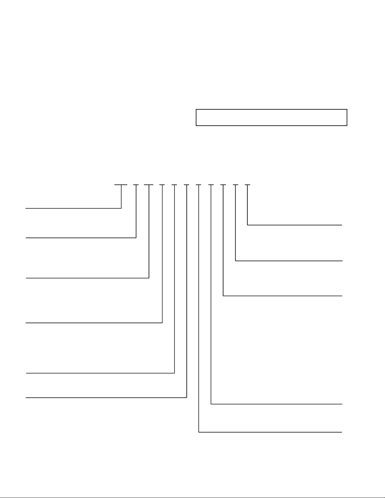
DOMESTIC UNITS — Standard 38AP unit packaging con-
38AP D 025 6 4 A 1 0 0 5 0
38AP – Split System Condensing Unit Packaging/Security Options
0 – Std Packaging
8 – Std Packaging, Bottom Skid
J – Bottom Skid, Top Crate, Bag
Controls/Communications Options
2 – Scrolling Marquee
3 – EMM, Scrolling Marquee
5 – No Display
Ambient/Capacity Control/
Interrupt Options
0 – Std Ambient, Std Compressor,
Std Interrupt
2 – Std Ambient, Digital Compressor,
Std Interru
pt
3 – Std Ambient, Std Compressor,
High Interrupt
5 – Std Ambient, Digital Compressor,
High Interrupt
6 – Low Ambient, Std Compressor,
Std Interrupt
8 – Low Ambient, Digital Compressor,
Std Interrupt
9 – Low Ambient, Std Compressor,
High Interrupt
C – Low Ambient, Digital Compressor,
High Interrupt
Line Length Options
1 – Standard Line Length
2 – Long Line Length Check Valves
Electrical Options
0 – Single Point Power, Terminal Block
1 – Single Point Power,
Non-Fused Disconnect
Refrigeration Circuit Options
*
D – Dual Refrigeration Circuit
S – Single Refrigeration Circuit
Revision Level
A – Current Revision Level
ylppuS rewoP
1 – 575-3-60
2 – 380-3-60
5 – 280/230-3-60
6 – 460-3-60
9 – 380/415-3-50
Condenser Coil/Low Sound Options
4 – MCHX, No Sound Treatment
5 – E-coat, MCHX, No Sound Treatment
C – MCHX, Low Sound Fan(s)
D
– E-coat MCHX, Low Sound Fan(s)
H – MCHX, Low Sound Fan(s), Compressor Blankets
J – E-coat MCHX, Low Sound Fan(s), Compressor Blankets
Nominal Capacity – Tons (kW)
025 – 25 (88) 050 – 50 (176) 090 – 90 (317)
027 – 27 (95) 060 – 60 (211) 100 – 100 (352)
030 – 30 (106) 070 – 70 (246)
040 – 40 (141) 080 – 80 (281)
LEGEND
*38APS units available in sizes 025-050 only.
EMM — Energy Management Module
MCHX — Microchannel Heat Exchanger
a38-7100.eps
Fig. 1 — Model Number Nomenclature
sists of coil protection only. Skids are not provided. If overhead
rigging is not available at the jobsite, place the unit on a skid or
pad before dragging or rolling. When rolling, use a minimum
of 3 rollers. When dragging, pull the pad or skid. Do not apply
force to the unit. When in final position, raise from above to lift
unit off the pad or skid.
EXPORT UNITS — All export units are mounted on skids
with vertical coil protection. Leave the unit on the skid until it
is in final position. While on the skid, the unit can be rolled or
skidded. Apply force to the skid, not to the unit. Use a minimum of 3 rollers when rolling. When in final position, raise
from above to remove the skid.
PLACING UNITS — When considering location of the unit,
be sure to consult National Electrical Code (NEC, U.S.A.) and
local code requirements. Allow sufficient space for airflow,
wiring, piping, and service. The placement area must be level
and strong enough to support the operating weight of the unit.
(See Table 5.) When unit is in proper location, use of mounting
holes in base rails is recommended for securing unit to
supporting structure. For mounting unit on vibration isolators,
4 x 24 in. perimeter support ASTM “C” channels between unit
and the isolators are recommended with a minimum of 4 channels per unit. Fasteners for mounting unit are field supplied.
See Fig. 4.
Refer to Fig. 5-8 for airflow clearances. Recommended
minimum clearances are 6 ft (1829 mm) for unrestricted airflow and service on sides of unit, 4 ft (1219 mm) on ends, and
unrestricted clear air space above the unit. Provide ample space
to connect liquid and suction lines to indoor unit. For multiple
units, allow 10 ft (3048 mm) separation between airflow
surfaces. If walls surround the unit, wall height should not exceed the top of the unit fan discharge. Installation in a pit is not
recommended.
IMPORTANT: Be sure to mount unit level to ensure
proper oil return to compressors.
Refer to Fig. 9 for outdoor fan and compressor layout.
Refer to Fig. 10 and 11 for unit piping installation. See
Table 6 for refrigerant specialties part numbers.
2
Page 3
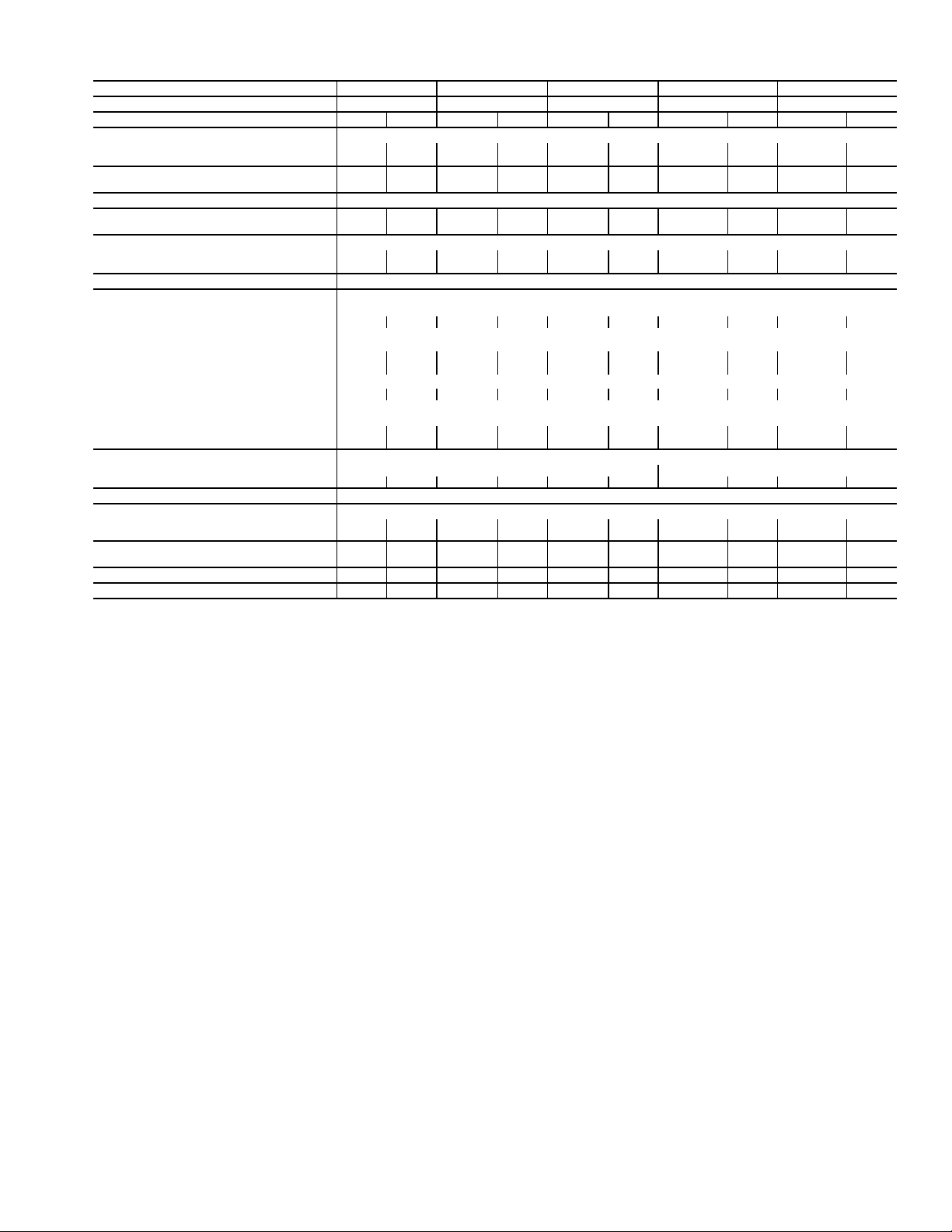
Table 1 — 38AP025-050 Unit Physical Data — English
38AP UNIT SIZE 025 027 030 040 050
NOMINAL CAPACITY, 50/60Hz (tons) 21/25 23/27 25/30 33/40 42/50
CIRCUIT Dual Single Dual Single Dual Single Dual Single Dual Single
OPERATING WEIGHTS (lb)
Standard 1095 1077 1258 1240 1264 1246 2094 1968 2120 1977
With Low Sound Option 1131 1113 1294 1276 1300 1282 2148 2022 2174 2031
APPROXIMATE REFRIGERANT CHARGE,
TYPICAL (lb)*
NITROGEN SHIPPING CHARGE 15 psig
COMPRESSOR
hp (Qty) (CKT A/CKT B)
CAPACITY STEPS
Standard 2222224343
Digital Option 22 22 22 22 22 22 44 33 44 33
CRANKCASE HEATER (W) (each compressor) 90
CONDENSER FANS
Standard Propeller Type - Direct Drive
Quantity 2222223333
RPM 1140 (60 Hz), 950 (50 Hz)
Diameter (in.) 30
Total Watts (60 Hz) 3300 3300 3300 3300 3300 3300 4200 4200 4200 4200
Total Watts (50 Hz) 2750 2750 2750 2750 2750 2750 3500 3500 3500 3500
Low Noise
Quantity 2222223333
RPM
Diameter (in.) 30
Total Watts (60 Hz) 2750 2750 2750 2750 2750 2750 3500 3500 3500 3500
Total Watts (50 Hz) 2300 2300 2300 2300 2300 2300 2900 2900 2900 2900
CONDENSER COIL MCHX Type
No. Coils per Circuit 11
sq ft 27.1 27.1 33.9 33.9 33.9 33.9 67.8 67.8 67.8 67.8
TEMPERATURE RELIEF Fusible Plug on Liquid Lines of Each Circuit - 210 F
CONNECTIONS (in.) ODF (CKT A/CKT B)
Suction Line 1
Liquid Line
MAXIMUM HEIGHT FOR 3° F SUBCOOLING
(ft)†
CAPACITY PER CIRCUIT (%) (CKT A/CKT B) 50/50 100 50/50 100 50/50 100 54/46 100 48/52 100
MINIMUM UNIT CAPACITY (%) 50 50 50 50 50 50 23 33 23 33
LEGEND
MCHX — Microchannel Heat Exchanger
ODF — Outside Diameter, Female
*Typical operating charge with 25 ft of interconnecting piping. Operating
charge is approximate for maximum system capacity. Unit is factory supplied
with nitrogen holding charge. Refrigerant charge for dual circuit units is the
total for both circuits.
†Maximum vertical separation between evaporator coil and condensing unit if
condensing unit is below the evaporator.
28 24 30 26 30 26 52 40 52 40
11 (2) 11 (2) 13 (2) 13 (2) 15 (2) 15 (2) 10 (2)/
8.5 (2)
13 (3) 11 (2)/
13 (2)
Shrouded Axial Fan - Direct Drive
850 (60 Hz), 700 (50 Hz)
3
/8 / 13/815/813/8 / 13/815/813/8 / 13/815/
5
/8 / 5/
5
5
/
8
/8 / 5/
8
5
5
/
8
/8 / 5/
8
8
15/8 / 15/
8
7
5
/
/8 / 5/
8
21/
8
8
15/8 / 15/
8
7
/
8
5
/8 / 5/
8
8
75 75 75 75 75 75 75 75 75 75
15 (3)
21/
7
/
8
8
3
Page 4
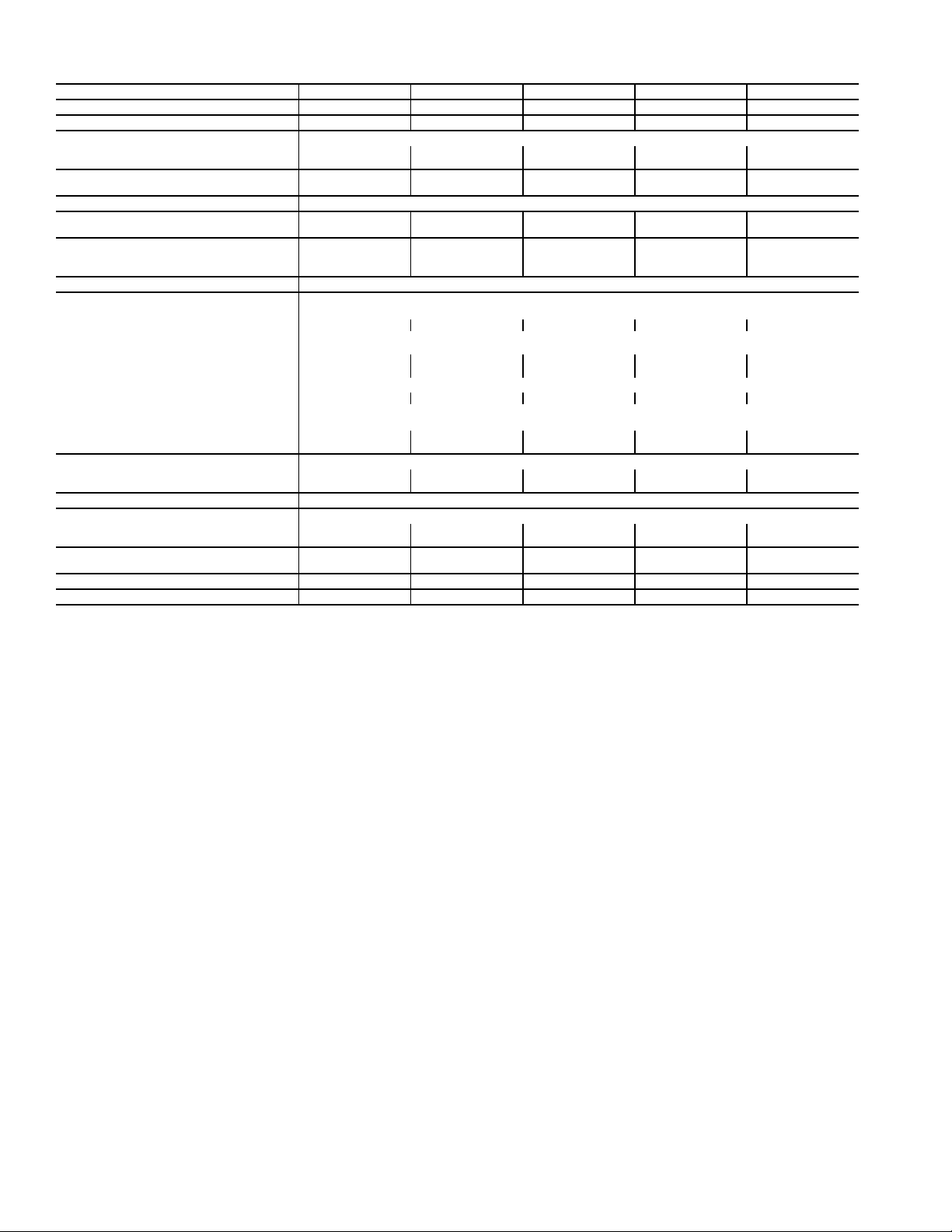
Table 2 — 38AP060-100 Unit Physical Data — English
NOMINAL CAPACITY, 50/60Hz (tons) 50/60 58/70 67/80 75/90 83/100
38AP UNIT SIZE 060 070 080 090 100
CIRCUIT Dual Dual Dual Dual Dual
OPERATING WEIGHTS (lb)
Standard 2227 2450 2610 2835 2844
With Low Sound Option 2299 2522 2700 2943 2952
APPROXIMATE REFRIGERANT CHARGE,
TYPICAL (lb)*
60 70 78 96 100
NITROGEN SHIPPING CHARGE 15 psig
COMPRESSOR
hp (Qty) (CKT A/CKT B)
CAPACITY STEPS
Standard 45566
Digital Option 44 55 55 66 66
13 (2)/15 (2) 15 (2)/11 (3) 15 (2)/15 (3) 13 (3)/15 (3) 15 (3)/15 (3)
CRANKCASE HEATER (W) (each compressor) 90
CONDENSER FANS
Standard Propeller Type - Direct Drive
Quantity 44566
RPM 1140 (60 Hz), 950 (50 Hz)
Diameter (in.) 30
Total Watts (60 Hz) 6200 6000 7500 9000 9000
Total Watts (50 Hz) 5150 5000 6250 7500 7500
Low Noise
Quantity 44566
RPM
Diameter (in.) 30
Total Watts (60 Hz) 5200 5000 6250 7500 7500
Total Watts (50 Hz) 4300 4150 5200 6250 6250
CONDENSER COIL MCHX Type
No. Coils per Circuit 1 2 2 to 3 3 3
sq ft 67.8 99.6 124.5 149.4 149.4
Shrouded Axial Fan - Direct Drive
850 (60 Hz), 700 (50 Hz)
TEMPERATURE RELIEF Fusible Plug on Liquid Lines of Each Circuit - 210 F
CONNECTIONS (in.) ODF (CKT A/CKT B)
Suction Line 1
Liquid Line
MAXIMUM HEIGHT FOR 3° F SUBCOOLING
(ft)†
5
/8 / 15/
5
/8 / 7/
8
8
15/8 / 21/
7
/8 / 7/
8
8
15/8 / 21/
7
/8 / 7/
8
8
21/8 / 21/
7
/8 / 7/
8
8
75 75 75 75 75
21/8 / 25/
7
/8 / 7/
8
8
CAPACITY PER CIRCUIT (%) (CKT A/CKT B) 46/54 47/53 40/60 46/54 50/50
MINIMUM UNIT CAPACITY (%) 23 24 20 15 17
LEGEND
MCHX — Microchannel Heat Exchanger
ODF — Outside Diameter, Female
*Typical operating charge with 25 ft of interconnecting piping. Operating
charge is approximate for maximum system capacity. Unit is factory supplied
with nitrogen holding charge. Refrigerant charge for dual circuit units is the
total for both circuits.
†Maximum vertical separation between evaporator coil and condensing unit if
condensing unit is below the evaporator.
4
Page 5
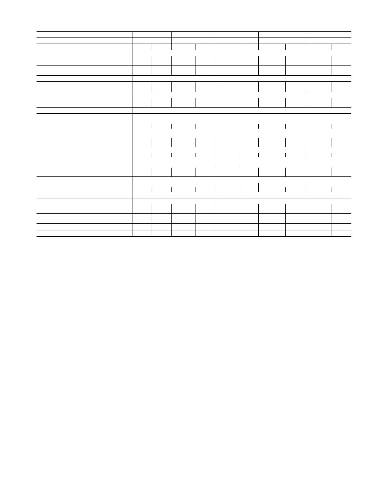
Table 3 — 38AP025-050 Unit Physical Data — SI
38AP UNIT SIZES 025 027 030 040 050
NOMINAL CAPACITY 50/60 Hz (kW) 74/88 81/95 88/106 116/141 148/176
CIRCUIT Dual Single Dual Single Dual Single Dual Single Dual Single
OPERATING WEIGHTS (kg)
Standard 497 489 571 562 573 565 950 893 961 897
With Low Sound Option 513 505 587 579 590 582 974 917 986 921
APPROXIMATE REFRIGERANT CHARGE,
TYPICAL (kg)*
NITROGEN SHIPPING CHARGE 1.03 bar
COMPRESSOR
kW (Qty) (CKT A/CKT B)
CAPACITY STEPS
Standard 222222 4 3 4 3
Digital Option 22 22 22 22 22 22 44 33 44 33
CRANKCASE HEATER (W) (each compressor) 90
CONDENSER FANS
Standard Propeller Type - Direct Drive
Quantity 222222 3 3 3 3
r/s 19 (60 Hz), 16 (50 Hz)
Diameter (mm) 762
Total Watts (60 Hz) 3300 3300 3300 3300 3300 3300 4200 4200 4200 4200
Total Watts (50 Hz) 2750 2750 2750 2750 2750 2750 3500 3500 3500 3500
Low Noise
Quantity 222222 3 3 3 3
r/s
Diameter (mm) 762
Total Watts (60 Hz) 2750 2750 2750 2750 2750 2750 3500 3500 3500 3500
Total Watts (50 Hz) 2300 2300 2300 2300 2300 2300 2900 2900 2900 2900
CONDENSER COIL MCHX Type
No. Coils per Circuit 11
sq m 2.5 2.5 3.2 3.2 3.2 3.2 6.3 6.3 6.3 6.3
TEMPERATURE RELIEF Fusible Plug on Liquid Lines of Each Circuit - 99 C
CONNECTIONS (in.) ODF (CKT A/CKT B)
Suction Line 1
Liquid Line
MAXIMUM HEIGHT FOR 1.7° C
SUBCOOLING (m)†
CAPACITY PER CIRCUIT (%) (CKT A/CKT B) 50/50 100 50/50 100 50/50 100 54/46 100 48/52 100
MINIMUM UNIT CAPACITY (%) 50 50 50 50 50 50 23 33 23 33
LEGEND
MCHX — Microchannel Heat Exchanger
ODF — Outside Diameter, Female
*Typical operating charge with 7.62 m of interconnecting piping. Operating
charge is approximate for maximum system capacity. Unit is factory supplied
with nitrogen holding charge. Refrigerant charge for dual circuit units is the
total for both circuits.
†Maximum vertical separation between evaporator coil and condensing unit if
condensing unit is below the evaporator.
12.7 10.9 13.6 11.8 13.6 11.8 23.6 18.1 23.6 18.1
8.2 (2) 8.2 (2) 9.7 (2) 9.7 (2) 11.2 (2) 11.2 (2) 7.5 (2)/
6.3 (2)
9.7 (3) 8.2 (2)/
9.7 (2)
11.2 (3)
Shrouded Axial Fan - Direct Drive
14 (60 Hz), 12 (50 Hz)
3
/8 / 13/815/813/8 / 13/815/813/8 / 13/815/
5
/8 / 5/
5
5
/
8
/8 / 5/
8
5
5
/
8
/8 / 5/
8
8
15/8 / 15/
8
7
5
/
/8 / 5/
8
21/
8
8
15/8 / 15/
8
7
/
8
5
/8 / 5/
8
8
23 23 23 23 23 23 23 23 23 23
21/
8
7
/
8
5
Page 6
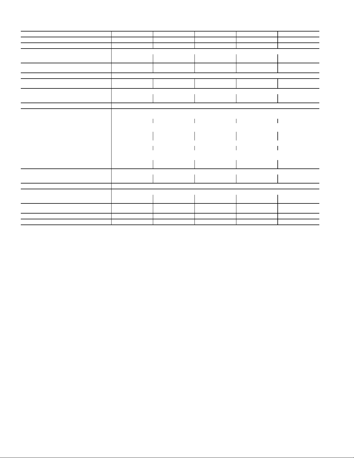
Table 4 — 38AP060-100 Unit Physical Data — SI
NOMINAL CAPACITY 50/60 Hz (kW) 176/211 204/246 236/281 264/317 292/352
38AP UNIT SIZES 060 070 080 090 100
CIRCUIT Dual Dual Dual Dual Dual
OPERATING WEIGHTS (kg)
Standard 1010 1111 1184 1286 1290
With Low Sound Option 1043 1144 1225 1335 1339
APPROXIMATE REFRIGERANT CHARGE,
TYPICAL (kg)*
27.2 31.8 35.4 43.5 45.4
NITROGEN SHIPPING CHARGE 1.03 bar
COMPRESSOR
kW (Qty) (CKT A/CKT B)
CAPACITY STEPS
Standard 45566
Digital Option 44 55 55 66 66
9.7 (2)/11.2 (2) 11.2 (2)/8.2 (3) 11.2 (2)/11.2 (3) 9.7 (3)/11.2 (3) 11.2 (3)/11.2 (3)
CRANKCASE HEATER (W) (each compressor) 90
CONDENSER FANS
Standard Propeller Type - Direct Drive
Quantity 44566
r/s 19 (60 Hz), 16 (50 Hz)
Diameter (mm) 762
Total Watts (60 Hz) 6200 6000 7500 9000 9000
Total Watts (50 Hz) 5150 5000 6250 7500 7500
Low Noise
Quantity 44566
r/s
Diameter (mm) 762
Total Watts (60 Hz) 5200 5000 6250 7500 7500
Total Watts (50 Hz) 4300 4150 5200 6250 6250
CONDENSER COIL MCHX Type
No. Coils per Circuit 1 2 2 - 3 3 - 3 3 - 3
sq m 6.3 9.3 11.6 13.9 13.9
Shrouded Axial Fan - Direct Drive
14 (60 Hz), 12 (50 Hz)
TEMPERATURE RELIEF Fusible Plug on Liquid Lines of Each Circuit - 99 C
CONNECTIONS (in.) ODF (CKT A/CKT B)
Suction Line 1
Liquid Line
MAXIMUM HEIGHT FOR 1.7° C
SUBCOOLING (m)†
5
/8 / 15/
5
/8 / 7/
8
8
15/8 / 21/
7
/8 / 7/
8
8
15/8 / 21/
7
/8 / 7/
8
8
21/8 / 21/
7
/8 / 7/
8
8
23 23 23 23 23
21/8 / 25/
7
/8 / 7/
8
8
CAPACITY PER CIRCUIT (%) (CKT A/CKT B) 46/54 47/53 40/60 46/54 50/50
MINIMUM UNIT CAPACITY (%) 23 24 20 15 17
LEGEND
MCHX — Microchannel Heat Exchanger
ODF — Outside Diameter, Female
*Typical operating charge with 7.62 m of interconnecting piping. Operating
charge is approximate for maximum system capacity. Unit is factory supplied
with nitrogen holding charge. Refrigerant charge for dual circuit units is the
total for both circuits.
†Maximum vertical separation between evaporator coil and condensing unit if
condensing unit is below the evaporator.
6
Page 7
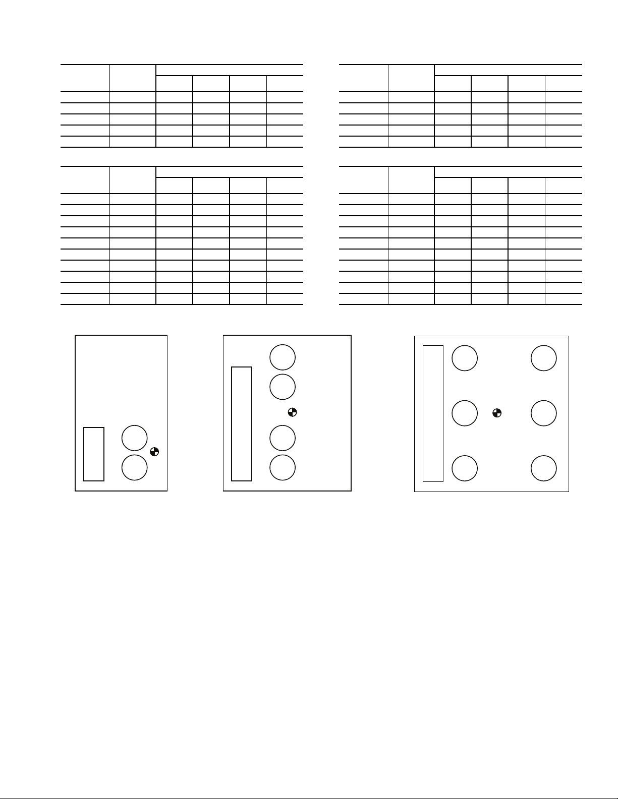
Table 5 — Operational Corner Weights with Refrigerant Charge (Approximate)
TOP VIEW, SIZES 070 TO 100
TOP VIEW,
SIZES 025 TO 030
TOP VIEW, SIZES 040 TO 060
Fig. 2 — Corner Weights
A
BC
D
COMP
COMP
CONTROL
BOX
A
BC
D
COMP
COMP
CONTROL BOX
COMP
COMP
A
BC
D
COMP
COMP
CONTROL BOX
COMP
COMP
COMP COMP
a38-7114
38APS Unit (lb)
38APS
UNIT
SIZE
025 1089 356 253 200 281
027 1255 396 291 240 327
030 1261 399 293 241 328
040 1998 619 616 380 382
050 2007 623 620 381 383
38APD
UNIT
SIZE
025 1107 360 258 204 285
027 1273 401 296 245 331
030 1279 404 297 245 333
040 2124 672 671 390 390
050 2150 683 684 392 391
060 2257 706 705 422 423
070 2494 723 620 532 620
080 2665 791 679 552 643
090 2901 759 750 692 700
100 2910 759 750 696 705
TOTAL
WEIGHT
TOTAL
WEIGHT
OPERATIONAL CORNER WEIGHT
ABCD
38APD Unit (lb)
OPERATIONAL CORNER WEIGHT
ABCD
38APS Unit (kg)
38APS
UNIT
SIZE
025 494 161 115 91 127
027 569 180 132 109 148
030 572 181 133 109 149
040 906 281 280 173 173
050 910 282 281 173 174
TOTAL
WEIGHT
OPERATIONAL CORNER WEIGHT
ABCD
38APD Unit (kg)
38APD
UNIT
SIZE
025 502 163 117 93 129
027 577 182 134 111 150
030 580 183 135 111 151
040 963 305 305 177 177
050 975 310 310 178 178
060 1024 320 320 192 192
070 1131 328 281 241 281
080 1209 359 308 250 292
090 1316 344 340 314 318
100 1320 344 340 316 320
TOTAL
WEIGHT
OPERATIONAL CORNER WEIGHT
ABCD
7
Page 8
Fig. 3 — Rigging Labels
Fig. 4 — Perimeter Support Channel
SIZES 025 TO 060 SIZES 070 TO 100
a38-7115
a38-7116
LEGEND
ASTM — American Society for
Testing and Materials
a38-7130
4 x 24 in.
ASTM “C”
CHANNEL
8
Page 9
UNIT
STANDARD
WEIGHT, lb (kg)
CENTER OF GRAVITY,
in. (mm)
HEIGHT,
in. (mm)
POWER ENTRY,
in. (mm)
SERVICE VALVE
CONNECTIONS, in. (mm)
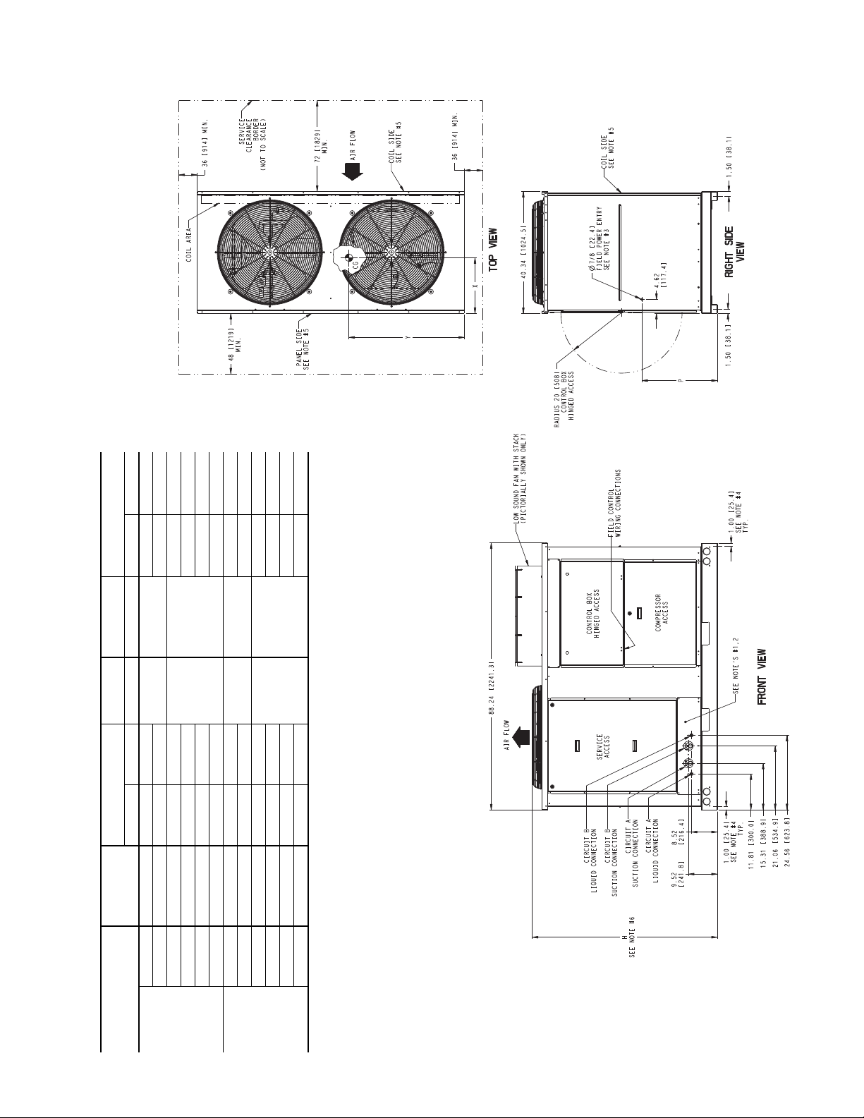
X Y H P Suction Liquid
Standard
38APS025 1077 (489) 17.8 (452) 36.9 (937)
61.0 (1549) 24.9 (632)
1
5
/
8
(41)
5
/
8
(16)
38APD025 1095 (497) 17.8 (452) 37.0 (940) 1
3
/
8
(35)
5
/
8
(16)
38APS027 1240 (563) 18.2 (462) 37.6 (955)
73.1 (1857) 36.9 (937)
1
5
/
8
(41)
5
/
8
(16)
38APD027 1258 (571) 18.2 (462) 37.6 (955) 1
3
/
8
(35)
5
/
8
(16)
38APS030 1246 (565) 18.2 (462) 37.5 (953) 1
5
/
8
(41)
7
/
8
(22)
38APD030 1264 (573) 18.2 (462) 37.6 (955) 1
3
/
8
(35)
5
/
8
(16)
Low Sound
38APS025 1113 (505) 17.8 (452) 36.9 (937)
66.5 (1689) 24.9 (632)
1
5
/
8
(41)
5
/
8
(16)
38APD025 1131 (513) 17.8 (452) 37.0 (940) 1
3
/
8
(35)
5
/
8
(16)
38APS027 1276 (579) 18.2 (462) 37.6 (955)
78.6 (1996) 36.9 (937)
1
5
/
8
(41)
5
/
8
(16)
38APD027 1294 (587) 18.2 (462) 37.6 (955) 1
3
/
8
(35)
5
/
8
(16)
38APS030 1282 (582) 18.2 (462) 37.5 (953) 1
5
/
8
(41)
7
/
8
(22)
38APD030 1300 (590) 18.2 (462) 37.6 (955) 1
3
/
8
(35)
5
/
8
(16)
NOTES:
1. Be sure to use a wet rag to remove all valve cores before brazing field piping.
2. Do not cap or otherwise obstruct the liquid line temperature relief.
3. A
7
/
8
in. (22.4 mm) diameter hole is provided for locating field power wiring. Actual hole size
required depends on field wire sizing.
4. A 0.437 in. (11.1 mm) diameter hole is used for mounting unit.
5. Unit must have clearances as follows:
Top - Do not restrict.
Coil End - 72 in. (1829) from solid surface.
Panel Side - 48 in. (1219) per NEC (National Electrical Code, U.S.A. Standard).
6. Unit height dimension for standard and low sound unit with stack fan option.
7. Installation in a pit is not recommended.
8. Unit can be handled using the fork truck lift pockets.
9. Dimensions shown in inches (mm).
a38-7101
Fig. 5 — 38AP Unit Dimensions, Sizes 025-030
9
Page 10
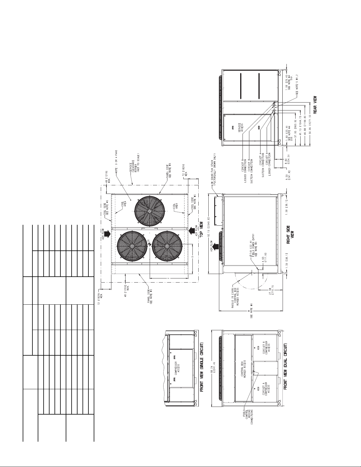
UNIT
STANDARD
WEIGHT, lb (kg)
CENTER OF GRAVITY,
in. (mm)
HEIGHT,
in. (mm)
SERVICE VALVE
CONNECTIONS, in. (mm)
X Y H Suction Liquid
Standard
38APS040 1968 (893) 35.0 (869) 44.0 (1118)
73.0 (1854)
2
1
/
8
(54)
7
/
8
(22)
38APD040 2094 (950) 33.7 (856) 44.1 (1120) 1
5
/
8
(41)
5
/
8
(16)
38APS050 1977 (897) 34.9 (886) 44.0 (1118) 2
1
/
8
(54)
7
/
8
(22)
38APD050 2120 (961) 33.4 (848) 44.1 (1120) 1
5
/
8
(41)
5
/
8
(16)
38APD060 2227 (1010) 34.4 (874) 44.1 (1120) 1
5
/
8
(41)
5
/
8
(16)
Low Sound
38APS040 2022 (917) 35.0 (869) 44.0 (1118)
78.5 (1994)
2
1
/
8
(54)
7
/
8
(22)
38APD040 2148 (974) 33.7 (856) 44.1 (1120) 1
5
/
8
(41)
5
/
8
(16)
38APS050 2031 (921) 34.9 (886) 44.0 (1118) 2
1
/
8
(54)
7
/
8
(22)
38APD050 2174 (986) 33.4 (848) 44.1 (1120) 1
5
/
8
(41)
5
/
8
(16)
38APD060 2299 (1043) 34.4 (874) 44.1 (1120) 1
5
/
8
(41)
5
/
8
(16)
NOTES:
1. Be sure to use a wet rag to remove all valve cores before brazing field piping.
2. Do not cap or otherwise obstruct the liquid line temperature relief.
3. A
7
/
8
in. (22.4 mm) diameter hole is provided for locating field power wiring.
Actual hole size required depends on field wire sizing.
4. A 0.437 in. (11.1 mm) diameter hole is used for mounting unit.
5. Unit must have clearances as follows:
Top - Do not restrict.
Coil End - 72 in. (1829) from solid surface.
Panel Side - 48 in. (1219) per NEC (National Electrical Code, U.S.A. Standard).
6. Unit height dimension for standard and low sound unit with stack fan option.
7. Installation in a pit is not recommended.
8. Unit can be handled using the fork truck lift pockets.
9. Dimensions shown in inches (mm).
10. Sizes 040 and 050 units have 3 condenser fans. Size 060 units have 4 con-
denser fans.
a38-7102
Fig. 6 — 38AP Unit Dimensions, Sizes 040-060
10
Page 11
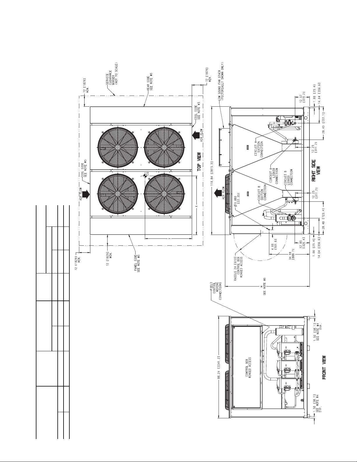
UNIT
STANDARD
WEIGHT, lb (kg)
CENTER OF GRAVITY,
in. (mm)
HEIGHT,
in. (mm)
SERVICE VALVE CONNECTIONS,
in. (mm)
Suction
Liquid
X Y H Circuit A Circuit B
Standard 38APD070 2450 (1111) 50.9 (1293) 40.6 (1031) 73.0 (1854) 2
1
/
8
(54) 1
5
/
8
(41)
7
/
8
(22)
Low Sound 38APD070 2522 (1144) 50.9 (1293) 40.6 (1031) 78.5 (1994) 2
1
/
8
(54) 1
5
/
8
(41)
7
/
8
(22)
NOTES:
1. Be sure to use a wet rag to remove all valve cores before brazing field piping.
2. Do not cap or otherwise obstruct the liquid line temperature relief.
3. A
7
/
8
in. (22.4 mm) diameter hole is provided for locating field power wiring.
Actual hole size required depends on field wire sizing.
4. A 0.437 in. (11.1 mm) diameter hole is used for mounting unit.
5. Unit must have clearances as follows:
Top - Do not restrict.
Coil, Panel and Rear Side - 72 in. (1829) from solid surface.
6. Unit height dimension for standard and low sound unit with stack fan option.
7. Installation in a pit is not recommended.
8. Unit can be handled using crane.
9. Dimensions shown in inches (mm).
a38-7103
Fig. 7 — 38AP Unit Dimensions, Size 070
11
Page 12

UNIT
STANDARD
WEIGHT, lb (kg)
CENTER OF GRAVITY,
in. (mm)
HEIGHT,
in. (mm)
SERVICE VALVE CONNECTIONS,
in. (mm)
Suction
Liquid
X Y H Circuit A Circuit B
Standard
38APD080 2610 (1184) 67.6 (1716) 40.2 (1020)
73.0 (1854)
2
1
/
8
(54) 1
5
/
8
(41)
7
/
8
(22)
38APD090 2835 (1286) 72.4 (1839) 43.3 (1099) 2
1
/
8
(54)
7
/
8
(22)
38APD100 2844 (1290) 72.6 (1844) 43.3 (1099) 2
1
/
8
(54)
7
/
8
(22)
Low Sound
38APD080 2700 (1225) 67.6 (1716) 40.2 (1020)
78.5 (1994)
2
1
/
8
(54) 1
5
/
8
(41)
7
/
8
(22)
38APD090 2943 (1335) 72.4 (1839) 43.3 (1099) 2
1
/
8
(54)
7
/
8
(22)
38APD100 2952 (1339) 72.6 (1844) 43.3 (1099) 2
1
/
8
(54)
7
/
8
(22)
NOTES:
1. Be sure to use a wet rag to remove all valve cores before brazing field piping.
2. Do not cap or otherwise obstruct the liquid line temperature relief.
3. A
7
/
8
in. (22.4 mm) diameter hole is provided for locating field power wiring.
Actual hole size required depends on field wire sizing.
4. A 0.437 in. (11.1 mm) diameter hole is used for mounting unit.
5. Unit must have clearances as follows:
Top - Do not restrict.
Coil, Panel and Rear Side - 72 in. (1829) from solid surface.
6. Unit height dimension for standard and low sound unit with stack fan option.
7. Installation in a pit is not recommended.
8. Unit can be handled using crane.
9. Dimensions shown in inches (mm).
10. Size 080 units have 5 condenser fans. Sizes 090 and 100 units have 6 con-
denser fans.
a38-7104
Fig. 8 — 38AP Unit Dimensions, Sizes 080-100
12
Page 13

OUTDOOR FAN LAYOUT (Single and Dual Circuit)
LEGEND
A—Circuit 1 Compressor
B—Circuit 2 Compressor
OFM — Outdoor Fan
a38-7131
Fig. 9 — Outdoor Fan and Compressor Layout
OFM1
OFM1
OFM1
OFM3
OFM3
OFM2
CONTROL BOX
TOP VIEW TOP VIEW TOP VIEW
SIZES 025-030 SIZES 040-050 SIZES 060-070
OFM1
CONTROL BOX
OFM2
OFM5
OFM1
CONTROL BOX
OFM2
OFM3
OFM4
OFM5
OFM3
CONTROL BOX
OFM2
TOP VIEW
SIZE 080
OFM6
CONTROL BOX
OFM2
TOP VIEW
SIZES 090-100
OFM4
OFM6
COMPRESSOR LAYOUT DUAL CIRCUIT
A1
A2
CONTROL BOX
B1
B2
TOP VIEW
A3
A2
A1
A1
B1
CONTROL BOX
TOP VIEW
SIZES 025-030 SIZES 040-060 SIZES 070-080
B1
B2
CONTROL BOX
B3
B1
B2
B3
CONTROL BOX
TOP VIEW
TOP VIEW
SIZES 090-100
COMPRESSOR LAYOUT SINGLE CIRCUIT
A1
A2
A1
CONTROL BOX
A2
A3
TOP VIEW
A1
A2
CONTROL BOX
TOP VIEW
SIZES 025-030 SIZES 040-050
13
Page 14

40RU
a38-7098_gs
LEGEND
*Field supplied.
†If double suction riser is required for piping
system, size short riser (3 ft maximum)
according to Fig. 12.
**Field supplied. See Table 6 for refrigerant spe-
cialties part numbers.
LLSV — Liquid Line Solenoid Valve
NEC — National Electrical Code
TXV — Thermostatic Expansion Valve
Piping
Double Riser Piping (if required)
NOTES:
1. All piping must follow standard refrigerant piping techniques. Refer to Carrier System
Design Manual for details.
2. All wiring must comply with the applicable local and national codes.
3. Wiring and piping shown are general points-of-connection guides only and are not
intended for, or to include all details for, a specific installation.
4. Install field-supplied disconnect switch in accordance with all local and national electrical
codes.
5. Liquid line solenoid valves (solenoid drop control) are not required but are recommended
to prevent refrigerant migration to the compressor.
6. Factory-supplied accumulator not shown.
7. Dual-circuit piping shown. Single-circuit piping is similar but would only have one suction
line and one liquid line.
8. A field-supplied, 5% bleed port TXV is required for every application.
9. Sight glass, LLSV, and filter drier are field supplied.
10. Long line length check valves are required for liquid line installation on all linear line
length applications of more than 100 ft (30.5 m). For any 025-030 size dual-circuit unit
application where evaporator is located higher than the condensing unit, check valves
are required for linear line length above 55 ft (16.8 m).
Fig. 10 — 38AP Unit Rooftop Installation
14
Page 15

a38-7099_gs
NOTES:
1. All piping must follow standard refrigerant piping techniques. Refer to Carrier System
Design Manual for details.
2. All wiring must comply with the applicable local and national codes.
3. Wiring and piping shown are general points-of-connection guides only and are not
intended for, or to include all details for, a specific installation.
4. Install field-supplied disconnect switch in accordance with all local and national electrical codes.
5. Liquid line solenoid valves (solenoid drop control) are not required but are recommended to prevent refrigerant migration to the compressor.
6. Factory-supplied accumulator not shown.
7. Dual-circuit piping shown. Single-circuit piping is similar but would only have one suction line and one liquid line.
8. A field-supplied, 5% bleed port TXV is required for every application.
9. Sight glass, LLSV, and filter drier are field supplied.
10. Long line length check valves are required for liquid line installation on all linear line
length applications of more than 100 ft (30.5 m). For any 025-030 size dual-circuit unit
application where evaporator is located higher than the condensing unit, check valves
are required for linear line length above 55 ft (16.8 m).
LEGEND
*Field supplied.
†Field supplied. See Table 6 for refrigerant spe-
cialties part numbers.
LLSV — Liquid Line Solenoid Valve
NEC — National Electrical Code
TXV — Thermostatic Expansion Valve
Piping
Fig. 11 — 38AP Unit Ground Level Installation
15
Page 16

38APS UNIT SIZE
025 24.0
027 26.7
030 31.1
040 39.8
050 48.1
Table 6 — Refrigerant Specialties Part Numbers
Tons LL Size (in.) LLSV
5
1
11/
1
/
8
7
/
8
5
/
8
7
/
8
5
/
8
7
/
8
1
/
8
5
/
8
7
/
8
8
7
/
8
1
/
8
EF680028 EF680032 KM680005 KH680002
EF680029 EF680032 KM680006 KH680003
EF680028 EF680032 KM680005 KH680002
EF680029 EF680032 KM680006 KH680003
EF680028 EF680032 KM680005 KH680002
EF680029 EF680032 KM680006 KH680003
EF680030 EF680032 KM680007 KH680004
EF680028 EF680032 KM680005 KH680003*
EF680029 EF680032 KM680006 KH680003
EF680030 EF680032 KM680007 KH680004
EF680029 EF680032 KM680006 KH680003
EF680030 EF680032 KM680007 KH680004
CIRCUIT A
LLSV Coil
24-v, 50/60 Hz
Sight Glass Filter Drier
38APD
UNIT
SIZE
025 12.0
027 13.3
030 15.6
040 21.0
050 23.8
060 26.8
070 31.8
080 31.3
090 40.3
100 48.0
Tons
LL Size
(in.)
1
5
1
5
1
5
7
—— — — —
5
7
5
7
5
7
—— — — — 1
5
7
1
5
7
1
5
7
1
7
11/8EF680030 EF680032 KM680007 KH680004 11/8EF680030 EF680032 KM680007 KH680004
LLSV
/
EF680031 EF680032 KM680004 KH680001
2
/
EF680028 EF680032 KM680005 KH680002
8
/
EF680031 EF680032 KM680004 KH680001
2
/
EF680028 EF680032 KM680005 KH680002
8
/
EF680031 EF680032 KM680004 KH680001
2
/
EF680028 EF680032 KM680005 KH680002
8
/
EF680029 EF680032 KM680006 KH680003
8
/
EF680028 EF680032 KM680005 KH680002
8
/
EF680029 EF680032 KM680006 KH680003
8
/
EF680028 EF680032 KM680005 KH680002
8
/
EF680029 EF680032 KM680006 KH680003
8
/
EF680028 EF680032 KM680005 KH680002
8
/
EF680029 EF680032 KM680006 KH680003
8
/
EF680028 EF680032 KM680005 KH680002
8
/
EF680029 EF680032 KM680006 KH680003
8
1
/8EF680030 EF680032 KM680007 KH680004 11/8EF680030 EF680032 KM680007 KH680004
/
EF680028 EF680032 KM680005 KH680002
8
/
EF680029 EF680032 KM680006 KH680003
8
1
/8EF680030 EF680032 KM680007 KH680004 11/8EF680030 EF680032 KM680007 KH680004
/
EF680028 EF680032 KM680005 KH680003*
8
/
EF680029 EF680032 KM680006 KH680003
8
1
/8EF680030 EF680032 KM680007 KH680004 11/8EF680030 EF680032 KM680007 KH680004
/
EF680029 EF680032 KM680006 KH680003
8
CIRCUIT A CIRCUIT B
LLSV Coil
24-v, 50/60 Hz
Sight
Glass
LEGEND
LL — Liquid Line
LLSV — Liquid Line Solenoid Valve
*Bushing required to fit
NOTE:
1. Filter driers have been sized based upon 1 to 2 psig pressure drop clean
in accordance with ARI Standard 710.
2. All pipe sizes are OD inches. Equivalent sizes in millimeters follow:
5
/8 in. line.
in. mm
1
/
2
5
/
8
7
/
8
1
/
1
12.7
15.9
22.2
28.6
8
Filter
Drier
Ton s
12.0
13.3
15.6
18.2
26.3
31.5
35.5
46.7
47.1
48.0
LL Size
(in.)
1
5
1
5
1
5
7
1
5
7
5
7
5
7
1
5
7
5
7
—— — — —
7
7
LLSV
/2EF680031 EF680032 KM680004 KH680001
/8EF680028 EF680032 KM680005 KH680002
/2EF680031 EF680032 KM680004 KH680001
/8EF680028 EF680032 KM680005 KH680002
/2EF680031 EF680032 KM680004 KH680001
/8EF680028 EF680032 KM680005 KH680002
/8EF680029 EF680032 KM680006 KH680003
/2EF680028 EF680032 KM680004 KH680001
/8EF680029 EF680032 KM680005 KH680002
/8EF680029 EF680032 KM680006 KH680003
/8EF680028 EF680032 KM680005 KH680002
/8EF680029 EF680032 KM680006 KH680003
/8EF680028 EF680032 KM680005 KH680002
/8EF680029 EF680032 KM680006 KH680003
/8EF680030 EF680032 KM680007 KH680004
/8EF680028 EF680032 KM680005 KH680002
/8EF680029 EF680032 KM680006 KH680003
/8EF680028 EF680032 KM680005 KH680003*
/8EF680029 EF680032 KM680006 KH680003
/8EF680029 EF680032 KM680006 KH680003
/8EF680029 EF680032 KM680006 KH680003
LLSV Coil
24-v, 50/60 Hz
Sight
Glass
Filter
Drier
16
Page 17

Step 3 — Make Refrigerant Piping
Fig. 12 — Double Suction Riser Construction
LEGEND
NOTES:
1. Short riser, pipe D, is used when routing suction line to
condensing unit connection. See table at right.
2. See Table 7 for values of A, B, and C.
A—Pipe A, Suction Riser, without Trap
B—Pipe B, Suction Riser with Trap
C—Suction Line to Condensing Unit
D—Pipe D, Suction Riser Short Lift
RED. — Reducer
STR — Street
38AP
UNIT
SIZE
D PIPE DIAMETER
Dual Circuit
Single Circuit
Circuit A Circuit B
in. mm in. mm in. mm
025 1
1
/
8
29 11/
8
29 13/
8
35
027 11/
8
29 11/
8
29 13/
8
35
030 11/
8
29 11/
8
29 13/
8
35
040 1
3
/
8
35 11/
8
29 15/
8
41
050 13/
8
35 13/
8
35 15/
8
41
060 13/
8
35 15/
8
41 — —
070 1
5
/
8
41 15/
8
41 — —
080 15/
8
41 15/
8
41 — —
090 1
5
/
8
41 15/
8
41 — —
100 1
5
/
8
41 15/
8
41 — —
a38-7132
Connections
CAUTION
Do NOT bury refrigerant piping underground. Failure to
comply could result in equipment damage.
The units have large suction lines to minimize friction losses. The units also have the ability to operate at low capacity.
Because of these capabilities, use special care with suction piping and suction risers to ensure proper compressor oil return
under all operating conditions. If the evaporator is above the
condensing unit, the maximum allowable vertical separation
between the condensing unit and the evaporator is 75 ft
(22.9 m) for all units. Size suction lines in accordance with
Table 7 and Fig. 12.
SIZE REFRIGERANT LINES — Consider the length of piping required between the condensing unit and indoor unit
(evaporator), the amount of liquid lift, and compressor oil return. Suction and liquid lines should be sized in accordance
with Table 7. Double suction risers may be required if con-
densing unit is located above the evaporator to assure proper
oil return at minimum load operating conditions. See Table 7
and Fig. 12. Note the indoor unit installtion instructions for additional information.
CAUTION
The field-supplied liquid line solenoid valve must be
installed at the evaporator to avoid possible compressor
damage during unit operation if the maximum allowable
evaporator size is exceeded per Table 8. See Fig. 13 (for
38APD025-100 dual-circuit units), or Fig. 14 (for
38APS025-050 single-circuit units).
17
Page 18

Table 7 — Refrigerant Piping Requirements
38APS025-050 Single-Circuit Units (60 Hz)
38APS
UNIT
SIZE
0-25 25-50 50-75 75-100 100-125 125-150 150-175 175-200
(0-7.6) (7.6-15.2) (15.2-22.9) (22.9-30.5) (30.5-38.1) (38.1-45.7) (45.7-53.3) (53.3-61.0)
LSLSLSLSLSLSLSLS
TOTAL LINEAR LENGTH OF INTERCONNECTING PIPE, ft (m)
025
027
030
040
050
5
/
13/
8
5
/
13/
8
5
/
13/
8
5
/
15/
8
7
/
15/
8
5
/
8
8
8
8
8
15/
8
5
/
15/
8
7
/
15/
8
7
/
21/
8
7
/
21/
8
7
/
7
/
7
/
7
/
7
/
8
8
8
8
8
15/
8
15/
8
21/
8
21/
8
21/811/
8
8
8
8
8
38APD025-100 Dual-Circuit Units (60 Hz)
TOTAL LINEAR LENGTH OF INTERCONNECTING PIPE, ft (m)
38APD UNIT
SIZE
Ckt A
025
Ckt B1/
Ckt A
027
Ckt B1/
Ckt A
030
Ckt B1/
Ckt A
040
Ckt B1/
Ckt A
050
Ckt B5/
Ckt A
060
Ckt B5/
Ckt A
070
Ckt B5/
Ckt A
080
Ckt B7/
Ckt A
090
Ckt B7/
Ckt A
100
Ckt B7/
LEGEND
L—Liquid Line
S—Suction Line
NOTES:
1. Shading indicates double suction riser required on units if condensing unit is located higher than evaporator.
2. Pipe sizes are based on an equivalent length equal to the maximum length of interconnecting piping, shown for each column,
plus 50% for fittings. Example: Equivalent length = Maximum
linear length x 1.5.
0-25 25-50 50-75 75-100 100-125 125-150 150-175 175-200
(0-7.6) (7.6-15.2) (15.2-22.9) (22.9-30.5) (30.5-38.1) (38.1-45.7) (45.7-53.3) (53.3-61.0)
LSLSLSLSLSLSLSLS
1
/
11/
2
11/
2
1
/
11/
2
11/
2
1
/
11/
2
11/
2
5
/
13/
8
11/
2
5
/
13/
8
13/
8
5
/
13/
8
13/
8
5
/
15/
8
15/
8
5
/
13/
8
15/
8
5
/
15/
8
15/
8
7
/
15/
8
15/
8
1
/
8
8
8
8
8
8
8
8
8
8
8
8
8
8
8
8
8
8
8
8
11/
2
1
/
11/
2
1
/
11/
2
1
/
11/
2
5
/
13/
8
5
/
13/
8
5
/
13/
8
5
/
13/
8
5
/
15/
8
5
/
15/
8
5
/
15/
8
7
/
15/
8
7
/
15/
8
7
/
21/
8
7
/
15/
8
7
/
21/
8
7
/
21/
8
7
/
21/
8
7
/
21/
8
7
/
21/
8
5
/
8
8
8
8
8
8
8
8
8
8
8
8
8
8
8
8
8
8
8
8
13/
8
5
/
8
5
/
8
5
/
8
5
/
8
5
/
8
5
/
8
5
/
8
7
/
8
7
/
8
7
/
8
7
/
8
7
/
8
7
/
8
7
/
8
7
/
8
7
/
8
7
/
8
7
/
8
7
/
8
8
13/
8
13/
8
13/
8
13/
8
13/
8
15/
8
15/
8
15/
8
15/
8
15/
8
21/
8
21/
8
21/
8
21/
8
21/
8
21/
8
21/811/821/811/825/811/825/811/825/811/825/
21/811/821/811/825/811/825/811/825/811/825/
21/811/821/811/825/811/825/811/825/811/825/
7
/
15/
8
7
/
21/
8
7
/
21/
8
7
/
21/
8
21/
8
5
/
8
5
/
8
5
/
8
5
/
8
5
/
8
5
/
8
7
/
8
5
/
8
7
/
8
7
/
8
7
/
8
7
/
8
7
/
8
7
/
8
7
/
8
7
/
8
7
/
8
7
/
8
8
8
8
11/
8
13/
8
13/
8
13/
8
13/
8
13/
8
13/
8
15/
8
15/
8
15/
8
21/
8
21/
8
21/
8
21/
8
21/
8
21/
8
21/
8
7
/
21/
8
7
/
21/
8
7
/
21/
8
25/
8
5
/
8
5
/
8
5
/
8
5
/
8
5
/
8
5
/
8
7
/
8
7
/
8
7
/
8
7
/
8
7
/
8
7
/
8
7
/
8
7
/
8
7
/
8
7
/
8
8
8
11/821/811/825/
8
11/825/811/825/
8
13/
8
13/
8
13/
8
13/
8
15/
8
15/
8
15/
8
15/
8
21/
8
21/
8
21/
8
21/
8
21/
8
21/
8
21/
8
21/
8
7
/
8
7
/
8
5
5
5
5
5
5
7
7
7
7
7
7
7
7
7
8
21/
8
21/
8
/
13/
8
/
8
/
8
/
8
/
8
/
8
/
8
/
8
/
8
/
8
/
8
/
8
/
8
/
8
/
8
8
13/
8
13/
8
13/
8
15/
8
15/
8
21/
8
15/
8
21/
8
21/
8
21/
8
21/811/821/811/821/
21/811/821/811/821/
21/811/821/811/825/
21/811/821/811/821/
7
/
21/
8
7
/
21/
8
7
/
21/
8
5
/
8
5
/
8
5
/
8
5
/
8
7
/
8
7
/
8
7
/
8
7
/
8
7
/
8
7
/
8
7
/
8
13/
13/
15/
15/
15/
15/
21/
15/
21/
21/
21/
7
/
8
8
7
/
8
8
11/
8
8
8
8
11/
8
11/
8
5
/
8
8
5
/
8
8
5
/
8
8
5
/
8
8
7
/
8
8
7
/
8
8
7
/
8
8
7
/
8
8
7
/
8
8
7
/
8
8
7
/
8
8
21/811/825/811/825/811/825/811/825/
7
21/
/
8
21/811/821/811/825/811/825/
8
21/
21/
21/
25/
25/
15/
15/
15/
15/
15/
15/
21/
21/
21/
21/
21/
8
8
8
8
8
8
8
8
8
8
8
8
8
8
8
8
8
8
8
8
8
8
8
8
8
3. Suction and liquid line sizing is based on pressure drop equiva-
lent to 2 F (1.1 C) at nominal rating conditions.
4. All pipe sizes are OD inches. Equivalent sizes in millimeters
follow:
in. mm
1
/
2
5
/
8
7
/
8
1
1
/
3
1
/
5
/
1
1
2
/
5
2
/
12.7
15.9
22.2
28.6
8
34.9
8
41.3
8
54.0
8
66.7
8
18
Page 19

Table 7 — Refrigerant Piping Requirements (cont)
38APS025-050 Single-Circuit Units (50 Hz)
38APS
UNIT
SIZE
0-25 25-50 50-75 75-100 100-125 125-150 150-175 175-200
(0-7.6) (7.6-15.2) (15.2-22.9) (22.9-30.5) (30.5-38.1) (38.1-45.7) (45.7-53.3) (53.3-61.0)
LSLSLSLSLSLSLSLS
TOTAL LINEAR LENGTH OF INTERCONNECTING PIPE, ft (m)
025
027
030
040
050
5
/
11/
8
5
/
13/
8
5
/
13/
8
5
/
13/
8
5
/
15/
8
5
/
8
8
8
8
8
13/
8
5
/
13/
8
5
/
15/
8
7
/
15/
8
7
/
21/
8
5
/
8
8
8
8
8
15/
8
5
/
8
7
/
8
7
/
8
7
/
8
15/
15/
21/
21/
8
8
8
8
8
38APD025-100 Dual-Circuit Units (50 Hz)
TOTAL LINEAR LENGTH OF INTERCONNECTING PIPE, ft (m)
38APD UNIT
SIZE
Ckt A
025
Ckt B1/
Ckt A
027
Ckt B1/
Ckt A
030
Ckt B1/
Ckt A
040
Ckt B1/
Ckt A
050
Ckt B5/
Ckt A
060
Ckt B5/
Ckt A
070
Ckt B5/
Ckt A
080
Ckt B5/
Ckt A
090
Ckt B5/
Ckt A
100
Ckt B5/
LEGEND
L—Liquid Line
S—Suction Line
NOTES:
1. Shading indicates double suction riser required on units if condensing unit is located higher than evaporator.
2. Pipe sizes are based on an equivalent length equal to the maximum length of interconnecting piping, shown for each column,
plus 50% for fittings. Example: Equivalent length = Maximum
linear length x 1.5.
0-25 25-50 50-75 75-100 100-125 125-150 150-175 175-200
(0-7.6) (7.6-15.2) (15.2-22.9) (22.9-30.5) (30.5-38.1) (38.1-45.7) (45.7-53.3) (53.3-61.0)
LSLSLSLSLSLSLSLS
1
/
11/
2
11/
2
1
/
11/
2
11/
2
1
/
11/
2
11/
2
1
/
11/
2
11/
2
5
/
13/
8
13/
8
5
/
13/
8
13/
8
5
/
13/
8
13/
8
5
/
13/
8
15/
8
5
/
13/
8
15/
8
5
/
15/
8
15/
8
1
/
8
8
8
8
8
8
8
8
8
8
8
8
8
8
8
8
8
8
8
8
11/
2
1
/
11/
2
1
/
11/
2
1
/
11/
2
1
/
11/
2
1
/
11/
2
5
/
13/
8
5
/
13/
8
5
/
13/
8
5
/
13/
8
5
/
13/
8
5
/
15/
8
5
/
15/
8
7
/
15/
8
5
/
15/
8
7
/
21/
8
7
/
15/
8
7
/
21/
8
7
/
21/
8
7
/
21/
8
1
/
8
8
8
8
8
8
8
8
8
8
8
8
8
8
8
8
8
8
8
8
11/
2
1
/
2
1
/
2
1
/
2
5
/
8
5
/
8
5
/
8
5
/
8
5
/
8
5
/
8
5
/
8
7
/
8
7
/
8
7
/
8
7
/
8
7
/
8
7
/
8
7
/
8
7
/
8
7
/
8
11/
11/
11/
13/
13/
13/
13/
15/
15/
15/
15/
15/
21/
15/
21/
21/
21/
21/
21/
8
8
8
8
8
8
8
8
8
8
8
8
8
8
8
8
8
8
8
8
5
/
15/
8
7
/
15/
8
7
/
15/
8
7
/
21/
8
7
/
21/
8
5
/
8
5
/
8
5
/
8
5
/
8
5
/
8
5
/
8
5
/
8
5
/
8
5
/
8
7
/
8
7
/
8
7
/
8
7
/
8
7
/
8
7
/
8
7
/
8
7
/
8
7
/
8
7
/
8
7
/
8
7
/
8
8
8
8
8
13/
8
13/
8
13/
8
13/
8
13/
8
13/
8
15/
8
13/
8
15/
8
15/
8
15/
8
21/
8
21/
8
21/
8
21/
8
21/
8
21/
8
21/
8
21/
8
21/
8
15/
8
7
/
15/
8
7
/
21/
8
7
/
21/
8
7
/
21/
8
5
/
8
5
/
8
5
/
8
5
/
8
5
/
8
5
/
8
5
/
8
5
/
8
7
/
8
7
/
8
7
/
8
7
/
8
7
/
8
7
/
8
7
/
8
7
/
8
7
/
8
7
/
8
7
/
8
7
/
8
8
8
8
8
8
13/
13/
13/
13/
13/
13/
15/
15/
15/
15/
15/
21/
21/
21/
21/
8
8
8
8
8
8
8
8
8
8
8
8
8
8
8
7
/
21/
8
7
/
21/
8
7
/
21/
8
7
/
21/
8
11/821/
5
/813/
5
/813/
5
/813/
5
/813/
5
/813/
5
/813/
5
/815/
5
/815/
7
/821/
7
/821/
7
/821/
7
/821/
7
/821/
7
/821/
7
/821/
7
/
11/
21/
8
7
/
21/
8
7
/
21/
8
7
/
21/
8
25/
8
5
/
8
5
/
8
5
/
8
5
/
8
5
/
8
5
/
8
7
/
8
7
/
8
7
/
8
7
/
8
7
/
8
7
/
8
7
/
8
7
/
8
7
/
8
8
8
8
8
8
8
8
8
8
8
8
8
8
8
8
8
8
8
8
8
13/
13/
13/
13/
15/
15/
15/
15/
21/
21/
21/
21/
21/
21/
21/
7
/
11/
21/
8
7
/
21/
8
7
/
21/
8
7
/
21/
8
25/
8
5
/
13/
8
5
/
13/
8
5
/
13/
8
5
/
13/
8
5
/
15/
8
5
/
15/
8
7
/
21/
8
7
/
15/
8
7
/
21/
8
7
/
21/
8
7
/
21/
8
7
/
21/
8
7
/
21/
8
7
/
21/
8
7
/
21/
8
8
8
8
8
8
8
8
8
8
8
8
8
8
8
8
8
8
8
8
8
21/811/821/811/825/811/825/
21/
7
/821/811/821/811/821/
8
21/811/821/811/825/811/825/
21/811/821/811/825/811/825/
21/811/821/811/825/811/825/
8
8
8
8
8
8
8
8
8
8
8
8
8
8
8
8
8
8
8
8
8
8
8
8
8
3. Suction and liquid line sizing is based on pressure drop equiva-
lent to 2 F (1.1 C) at nominal rating conditions.
4. All pipe sizes are OD inches. Equivalent sizes in millimeters
follow:
in. mm
1
/
5
/
7
/
1
1
3
1
5
1
1
2
5
2
12.7
2
15.9
8
22.2
8
/
28.6
8
/
34.9
8
/
41.3
8
/
54.0
8
/
66.7
8
19
Page 20

38APS
LEGEND
—
Suction Riser
without Trap
—
Suction Riser
with Trap
—
Suction Line to
Condensing Unit
—
Pipe Diameter to be
as Listed in Fig. 12.
a38-4149tf
SUCTION LINE PIPING
UNIT
SIZE
0-25 25-50 50-75 75-100 100-125 125-150 150-175 175-200
(0-7.6) (7.6-15.2) (15.2-22.9) (22.9-30.5) (30.5-38.1) (38.1-45.7) (45.7-53.3) (53.3-61.0)
ABCABCABCABCABCABCABCABC
025 ————————————1
027 —————————13/815/821/813/815/821/813/815/821/813/815/821/813/815/821/
030 ——————13/815/821/813/815/821/813/815/821/813/815/821/813/815/821/813/815/821/
040 ———13/815/821/813/815/821/813/815/821/813/815/821/813/815/821/815/821/825/815/821/825/
050 ———13/815/821/813/815/821/813/815/821/815/821/825/815/821/825/815/821/825/815/821/825/
38APD UNIT
SIZE
0-25 25-50 50-75 75-100 100-125 125-150 150-175 175-200
(0-7.6) (7.6-15.2) (15.2-22.9) (22.9-30.5) (30.5-38.1) (38.1-45.7) (45.7-53.3) (53.3-61.0)
ABCABCABCABCABCABCABCABC
Ckt A————————————————————————
025
Ckt B————————————————————————
Ckt A————————————————————————
027
Ckt B————————————————————————
Ckt A————————————————————————
030
Ckt B————————————————————————
Ckt A———————————————1
040
Ckt B—————————————————————13/815/821/
Ckt A————————————1
050
Ckt B—————————13/815/821/813/815/821/813/815/821/813/815/821/813/815/821/
Ckt A—————————1
060
Ckt B——————13/815/821/813/815/821/813/815/821/813/815/821/813/815/821/813/815/821/
Ckt A——————1
070
Ckt B — — — 13/815/821/813/815/821/813/815/821/813/815/821/813/815/821/813/815/821/815/821/825/
Ckt A——————1
080
Ckt B — — — 13/815/821/813/815/821/813/815/821/815/821/825/815/821/825/815/821/825/815/821/825/
Ckt A — — — 1
090
Ckt B — — — 13/815/821/813/815/821/813/815/821/815/821/825/815/821/825/815/821/825/815/821/825/
Ckt A — — — 1
100
Ckt B — — — 13/815/821/813/815/821/813/815/821/815/821/825/815/821/825/815/821/825/815/821/825/
LEGEND
——Not Required
Pipe A — Suction Riser without Trap
Pipe B — Suction Riser with Trap
Pipe C — Suction Line Condensing Unit
1. Refer to the figure located to the right for suction line piping locations.
2. Pipe sizes are based on an equivalent length equal to the maximum
length of interconnecting piping, shown for each column, plus 50% for
fittings.
3. Suction and liquid line sizing is based on pressure drop equivalent to 2 F
(1.1 C) at nominal rating conditions.
4. All pipe sizes are OD inches. Equivalent sizes in millimeters follow:
Table 7 — Refrigerant Piping Requirements (cont)
38APS025-50 Single-Circuit Units Double Suction Riser (60 Hz)
TOTAL LINEAR LENGTH OF INTERCONNECTING PIPE, ft (m)
3
/815/821/813/815/821/813/815/821/813/815/821/
38APD025-100 Dual-Circuit Units Double Suction Riser (60 Hz)
TOTAL LINEAR LENGTH OF INTERCONNECTING PIPE, ft (m)
3
/815/821/813/815/821/813/815/821/
3
/815/821/813/815/821/813/815/821/813/815/821/
3
/815/821/813/815/821/813/815/821/813/815/821/813/815/821/
3
/815/821/813/815/821/813/815/821/813/815/821/813/815/821/813/815/821/
3
/815/821/813/815/821/813/815/821/813/815/821/813/815/821/813/815/821/
3
/815/821/813/815/821/813/815/821/813/815/821/813/815/821/815/821/825/815/821/825/
3
/815/821/813/815/821/813/815/821/815/821/825/815/821/825/815/821/825/815/821/825/
in. mm
1
/
2
5
/
8
7
/
8
1
/
1
3
/
1
5
1
/
1
/
2
5
/
2
12.7
15.9
22.2
28.6
8
34.9
8
41.3
8
54.0
8
66.7
8
8
8
8
8
8
8
8
8
8
8
8
8
8
8
8
8
8
8
8
20
Page 21

LEGEND
—
Suction Riser
without Trap
—
Suction Riser
with Trap
—
Suction Line to
Condensing Unit
—
Pipe Diameter to be
as Listed in Fig. 12.
a38-4149tf
SUCTION LINE PIPING
Table 7 — Refrigerant Piping Requirements (cont)
38APS025-50 Single-Circuit Units Double Suction Riser (50 Hz)
38APS
UNIT
SIZE
0-25 25-50 50-75 75-100 100-125 125-150 150-175 175-200
(0-7.6) (7.6-15.2) (15.2-22.9) (22.9-30.5) (30.5-38.1) (38.1-45.7) (45.7-53.3) (53.3-61.0)
ABCABCABCABCABCABCABCABC
025 ———————————————1
027 ———————————————13/815/821/813/815/821/813/815/821/
030 ————————————13/815/821/813/815/821/813/815/821/813/815/821/
040 ——————13/815/821/813/815/821/813/815/821/813/815/821/813/815/821/813/815/821/
050 ———13/815/821/813/815/821/813/815/821/813/815/821/813/815/821/815/821/825/815/821/825/
38APD025-100 Dual-Circuit Units Double Suction Riser (50 Hz)
38APD UNIT
SIZE
Ckt A————————————————————————
025
Ckt B————————————————————————
Ckt A————————————————————————
027
Ckt B————————————————————————
Ckt A————————————————————————
030
Ckt B————————————————————————
Ckt A—————————————————————1
040
Ckt B————————————————————————
Ckt A———————————————1
050
Ckt B———————————————13/815/821/813/815/821/813/815/821/
Ckt A———————————————1
060
Ckt B—————————13/815/821/813/815/821/813/815/821/813/815/821/813/815/821/
Ckt A—————————1
070
Ckt B——————13/815/821/813/815/821/813/815/821/813/815/821/813/815/821/813/815/821/
Ckt A—————————1
080
Ckt B — — — 13/815/821/813/815/821/813/815/821/813/815/821/813/815/821/815/821/825/815/821/825/
Ckt A——————1
090
Ckt B — — — 13/815/821/813/815/821/813/815/821/813/815/821/813/815/821/815/821/825/815/821/825/
Ckt A — — — 1
100
Ckt B — — — 13/815/821/813/815/821/813/815/821/813/815/821/813/815/821/815/821/825/815/821/825/
——Not Required
Pipe A — Suction Riser without Trap
Pipe B — Suction Riser with Trap
Pipe C — Suction Line Condensing Unit
1. Refer to the figure located to the right for suction line piping locations.
2. Pipe sizes are based on an equivalent length equal to the maximum
length of interconnecting piping, shown for each column, plus 50% for
fittings.
3. Suction and liquid line sizing is based on pressure drop equivalent to 2 F
(1.1 C) at nominal rating conditions.
4. All pipe sizes are OD inches. Equivalent sizes in millimeters follow:
0-25 25-50 50-75 75-100 100-125 125-150 150-175 175-200
(0-7.6) (7.6-15.2) (15.2-22.9) (22.9-30.5) (30.5-38.1) (38.1-45.7) (45.7-53.3) (53.3-61.0)
ABCABCABCABCABCABCABCABC
3
/815/821/813/815/821/813/815/821/813/815/821/813/815/821/815/821/825/815/821/825/
LEGEND
in. mm
1
/
2
5
/
8
7
/
8
1
/
1
3
/
1
5
1
/
1
/
2
5
/
2
12.7
15.9
22.2
28.6
8
34.9
8
41.3
8
54.0
8
66.7
8
TOTAL LINEAR LENGTH OF INTERCONNECTING PIPE, ft (m)
3
/815/821/813/815/821/813/815/821/
TOTAL LINEAR LENGTH OF INTERCONNECTING PIPE, ft (m)
3
/815/821/
3
/815/821/813/815/821/813/815/821/
3
/815/821/813/815/821/813/815/821/
3
/815/821/813/815/821/813/815/821/813/815/821/813/815/821/
3
/815/821/813/815/821/813/815/821/813/815/821/813/815/821/
3
/815/821/813/815/821/813/815/821/813/815/821/813/815/821/813/815/821/
8
8
8
8
8
8
8
8
8
8
8
8
8
8
8
8
8
8
21
Page 22

LIQUID LINE SOLENOID VALVE — Field-supplied
liquid line solenoid valve(s) must be installed at the evaporator
if coil surface area is exceeded per Table 8. Install liquid line
solenoid valve just ahead of the TXVs (thermostatic expansion
valves) which will be mounted at the evaporator. See Fig. 13
(for 38APD025-100 dual-circuit units), or Fig. 14 (for
38APS025-050 single-circuit units). Refer to Table 6.
THERMOSTATIC EXPANSION VALVES — All 38AP
units must be installed with 5% bleed TXVs to ensure proper
unit operation.
To achieve good mixing of the refrigerant leaving the evap-
orator suction header for proper sensing by the TXV bulb:
1. Install a minimum of two 90-degree elbows upstream
of the TXV bulb location. See Fig. 15 for dual-circuit
units and Fig. 16 for single-circuit units.
2. Locate the TXV bulb on a vertical riser, where possible. If a horizontal location is necessary, secure the
bulb at approximately the 4 o’clock position.
If an oil return connection is located at the bottom of the
evaporator suction header, tee-in this connection ahead of first
mixing elbow. See Fig. 15 (for dual-circuit units) or Fig. 16
(for single-circuit units). When the compressor is below the
evaporator, the riser at the evaporator should extend to the top
of the evaporator section. After the riser is installed, the suction
line can elbow down immediately. Refer to the evaporator
product data for sizing information.
LIQUID LINE FILTER DRIER — Installation of a field-
supplied filter drier and sight glasses in each refrigerant circuit
is required. Select the filter drier for maximum unit capacity
and minimum pressure drop. Figure 13 (for dual-circuit units)
or Fig. 14 (for single-circuit units) shows required location of
solenoid valves and recommended locations for the filter driers
and sight glasses. Complete the refrigerant piping from the
evaporator to the condenser before opening the liquid and suction lines at the condenser. Refer to Table 6.
CAUTION
For all units with liquid lines of 100 ft (30.5 m) or more or
any 025-030 size dual circuit unit application where evaporator is located higher than the condensing unit and liquid
lines exceed 55 feet (16.8 m), a long line option kit must be
installed to prevent compressor failure. The long line
option kit must be mounted in the liquid line near the condensing unit. See Fig. 17.
LONG LINE APPLICATIONS — A long line option kit
must be installed for:
1. Any 025-030 size dual circuit unit where the evaporator is located higher than the condensing unit and the
linear line length exceeds 55 ft (16.8 m).
2. Any size dual or single circuit unit with linear line
length of 100 ft (30.5 m) or more.
The kit consists of a liquid line check valve and a bypass
check valve to prevent charge migration to compressor. The
long line option kit must be mounted in the liquid line near the
condensing unit. The kit may be mounted in any orientation,
horizontally or vertically. See Fig. 17 for orientation and
Fig. 11 for location.
HOT GAS BYPASS — Hot gas bypass is not recommended.
If hot gas bypass is used, it should be introduced before the
evaporator.
FINAL CONNECTION AND LEAK TEST
CAUTION
The 38AP unit is shipped with a nitrogen holding charge.
Use caution when relieving unit pressure to avoid possible
equipment damage or personal injury.
Relieve the pressure caused by the nitrogen holding charge.
Connect liquid line and suction line to field piping. Refer to
Fig. 5-8 for circuit orientation.
IMPORTANT: Protect the liquid and suction service
valves from the heat of brazing. Schrader valve cores
must be removed from the liquid and suction service
valves before brazing in field connection piping to avoid
damage. Reinsert cores after brazing is completed.
The refrigerant system must not be opened and exposed to
atmosphere for longer than 15 minutes. Connection and pumpdown should be made as soon as possible to avoid acids
forming in the compressor POE (polyolester) oils, which could
damage the compressors.
Leak test the entire system by using soap bubbles and nitrogen or R-410A and an electronic leak detector.
Purge nitrogen or recover R-410A from system after completion of leak-checking procedure. Repair leak if one is found.
When finished, evacuate and dehydrate system using the following method.
EVACUATION AND DEHYDRATION — Because the
38AP systems use polyolester oil, which can absorb moisture,
it is important to minimize the amount of time that the system
interior is left exposed to the atmosphere. Minimizing the
exposure time of the oil to the atmosphere will minimize the
amount of moisture that needs to be removed during
evacuation.
Once all of the piping connections are complete, leak test
the unit and then pull a deep dehydration vacuum. Connect the
vacuum pump to the charging valve in the suction line and to
the liquid line service valve. For best results, it is recommended
that a vacuum of at least 500 microns (0.5 mm Hg) be obtained. Afterwards, to ensure that no moisture is present in the
system, perform a standing vacuum-rise test.
With the unit in deep vacuum (500 microns or less), isolate
the vacuum pump from the system. Observe the rate-of-rise of
the vacuum in the system. If the vacuum rises by more than
50 microns in a 30-minute time period, then continue the dehydration process. Maintain a vacuum on the system until the
standing vacuum requirement is met. This will ensure a dry
system.
By following these evacuation and dehydration procedures,
the amount of moisture present in the system will be minimized. It is required that liquid line filter driers be installed between the condenser(s) and the expansion devices to capture
any foreign debris and provide additional moisture removal capacity. Be sure to consider the pressure drop of the filter drier
when determining piping requirements.
22
Page 23

LEGEND
*Field-supplied.
†Field-supplied when required. See Table 8.
Fig. 13 — Required Location of Solenoid Valves and Recommended Filter Drier and
Sight Glass Locations for 38APD025-100 Dual-Circuit Units
LLS — Liquid Line Solenoid
TXV — Thermostatic Expansion Valve
*Field-supplied.
†Field-supplied when required. See Table 8.
Fig. 14 — Required Location of Solenoid Valves and Recommended Filter Drier and
Sight Glass Locations for 38APS025-050 Single-Circuit Units
a38-7117
SECTION 1
SECTION 1
SECTION 2
SECTION 2
SOLENOID VALVE†
SOLENOID VALVE†
LIQUID
LINE
LIQUID
LINE
a38-7118
†
†
23
Page 24

SECTION
SECTION
SECTION
SECTION
a38-7120
SECTION
SECTION
SECTION
SECTION
LEGEND
NOTE: For units with single condensate pan, lower coil section is first on, last off.
Fig. 16 — Typical Piping Connections for Face Split Coils for 38APS025-050 Single-Circuit Units
TXV — Thermostatic Expansion Valve
TYP — Ty p i ca l
LEGEND
NOTE: For units with single condensate pan, lower coil section is first on, last off.
Fig. 15 — Typical Piping Connections for Face Split Coils for 38APD025-100 Dual-Circuit
TXV — Thermostatic Expansion Valve
TYP — Ty p ic a l
a38-7121
24
Page 25

Table 8 — Requirements for Installation of Liquid Line Solenoid Valve
Fig. 17 — Long Line Option Kit Installation
a38-7119
NOTE: Locate long line kit as close to the
condensing unit as possible.
38AP UNIT
SIZE
025
027
030
040
050
060
070
080
090
100
MAXIMUM ALLOWABLE EVAPORATOR SURFACE AREA
CIRCUIT
Circuit A 18.9 12.7 9.5 36.1 28.1
Circuit B 18.9 12.7 9.5 36.1 28.1
Single Circuit 37.9 25.3 18.9 72.3 56.3
Circuit A 21.7 14.5 10.9 41.4 32.3
Circuit B 25.6 17.1 12.8 48.9 38.1
Single Circuit 47.3 31.6 23.7 90.3 70.4
Circuit A 21.7 14.5 10.9 41.4 32.3
Circuit B 25.6 17.1 12.8 48.9 38.1
Single Circuit 47.3 31.6 23.7 90.3 70.4
Circuit A 47.3 31.6 23.7 — —
Circuit B 47.3 31.6 23.7 — —
Single Circuit 94.7 63.3 47.3 — —
Circuit A 47.3 31.6 23.7 — —
Circuit B 47.3 31.6 23.7 — —
Single Circuit 94.7 63.3 47.3 — —
Circuit A 47.3 31.6 23.7 — —
Circuit B 47.3 31.6 23.7 — —
Circuit A 69.7 46.6 34.9 — —
Circuit B 69.7 46.6 34.9 — —
Circuit A 69.7 46.6 34.9 — —
Circuit B 104.6 69.9 52.3 — —
Circuit A 104.6 69.9 52.3 — —
Circuit B 104.6 69.9 52.3 — —
Circuit A 104.6 69.9 52.3 — —
Circuit B 104.6 69.9 52.3 — —
4-Row,
1
/2 in. Tube 6-Row, 1/2 in. Tube 8-Row, 1/2 in. Tube 3-Row, 3/8 in. Tube 4-Row, 3/8 in. Tube
WITHOUT LIQUID LINE SOLENOID VALVE (sq ft)
25
Page 26

Step 4 — Make Electrical Connections
WARNING
Before performing service or maintenance operations on
unit, turn off main power switch to unit. Electrical shock
could cause personal injury.
CONTROL POWER — Control power is obtained from the
main power supply and does NOT require a separate source. A
toggle switch (marked Emergency On-Off on the unit label
diagram and by the switch) allows the control circuit to be
manually disconnected when necessary. Crankcase heaters are
in an operable state when this switch is in the Off position. All
field control wiring must comply with applicable local and
national codes.
IMPORTANT: When starting up this equipment for
operation, be sure to check tightness of all electrical terminal connections, clamps, screws, etc., as they may
have become loose during shipment. It is also advisable
to re-tighten all electrical connections after equipment
has been in operation and components have reacted to
operating temperature.
POWER SUPPLY — The electrical characteristics of the
available power supply must agree with the unit nameplate
rating. Supply voltage must be within the limits shown in
Tables 9-12. See Table 13 for incoming power options.
IMPORTANT: Operating unit on improper supply
voltage or with excessive phase imbalance constitutes
abuse and may adversely affect Carrier warranty.
CAUTION
Proper rotation of condenser fan(s) MUST be verified
before compressors are started. Consult the Controls, StartUp and Operation guide provided with the 38AP units for
correct procedure. Failure to comply could result in possible equipment damage.
POWER WIRING — All power wiring must comply with
applicable local and national codes. Install field-supplied
branch circuit fused disconnect per NEC (National Electrical
Code, U.S.A) of a type that can be locked OFF or OPEN. Disconnect must be within sight and readily accessible from the
unit in compliance with NEC Article 440-14.
General Wiring Notes:
1. The control circuit does NOT require a separate power
source. Control circuit power is obtained by a step-down
transformer from the main three-phase power supply. Be
sure that the appropriate connection tap is connected on
all transformers for the supply voltage.
2. A low-voltage terminal strip (LVT) is provided for
field-wired control devices.
NOTE: The field-supplied disconnect should never be off
except when unit is being serviced or is to be down for a prolonged period.
3. Power entry is at one end only.
4. All field power enters the unit through a hole located in
the corner post of the unit or the bottom of the control box
shelf. Refer to Fig. 18 for field power wiring details. Refer to Fig. 5-8 for exact location of field power entry.
5. Terminals for field power supply are suitable only for
copper conductors. Insulation must be rated 75 C
minimum.
6. Units with high short circuit ratings and terminal block
option require that specific fuses be applied to achieve
this rating. Refer to Table 13.
IMPORTANT: For 208-v systems, the connection tap
for all transformers must be changed. The factory
default setting is for 230-v. Failure to connect to the
proper tap may result in unreliable operation.
FIELD CONTROL WIRING — The standard unit control is
microprocessor based which supports multiple control
configurations. See Fig. 19 for EAT (evaporator air temperature sensor) and SAT (supply air temperature sensor) layout.
Figures 20-24 show specific field wiring, depending on unit
configuration and desired control requirements.
Constat Volume Application Control Options
1. Two-Stage Thermostat (Part No. 33CS2PP2S-01) —
Refer to Fig. 20.
2. Two-Stage Thermostat (Part No. 33CS2PP2S-01) with
Multi-Step Control — Refer to Fig. 21. This thermostat also requires installation of supply-air temperature
sensor and return-air temperature sensor (Part No.
33ZCSENSAT).
3. Space Sensor Control — Refer to Fig. 22. This control
also requires installation of supply-air temperature
sensor and return-air temperature sensor (Part No.
33ZCSENSAT).
a. Space Temperature Sensor with Occupancy Over-
ride Button (Part No. 33ZCT55SPT)
b. Space Temperature Sensor with Occupancy Over-
ride Button and Set Point Adjustment Slidebar
(Part No. 33ZCT56SPT)
c. Space Temperature Sensor with Occupancy Over-
ride Button, Set Point Adjustment Slidebar, and
LCD (liquid crystal display) Display (Part No.
33ZCT59SPT)
Variable Air Volume Application Control Options
1. Discharge-air temperature control requires installation
of supply-air temperature sensor and return-air
temperature sensor (Part No. 33ZCSENSAT). Refer to
Fig. 23.
2. Interface with building automation system may require
EMM (energy management module) or translator
accessory. Refer to Fig. 23.
Energy Management Module (EMM) Option
is available for factory or field installation. See Fig. 24 for
EMM field wiring.
— The EMM
26
Page 27

Fig. 18 — Field Power Wiring
LEGEND
NOTES:
1. Factory wiring is in accordance with UL 1995 standards. Field modifications
or additions must be in compliance with all applicable codes.
2. All units or modules have single point primary power connection. Main
power must be supplied from a field or factory-supplied disconnect.
3. Wiring for main field supply must be rated 75 C. Use copper conductors only.
a. Incoming wire size range for terminal block with MCA (minimum circuit
amps) up to 175 amps is 14 AWG (American Wire Gage) to 2/0.
b. Incoming wire size range for terminal block with MCA from 175.1 amps to
420 amps is 2 AWG to 600 kcmil.
c. Incoming wire size range for non-fused disconnect with MCA up to
100 amps is 14 AWG to 1/0.
d. Incoming wire size range for non-fused disconnect with MCA from
100.1 amp to 200 amps is 6 AWG to 350 kcmil.
e. Incoming wire size range for non-fused disconnect with MCA from
200.1 amp to 450 amps is 3/0 to 500 kcmil.
4. Refer to certified dimensional drawings for exact locations of the main power
and control power entrance locations.
EQUIP GND — Equipment Ground
NEC — National Electrical Code
a38-7122
Fig. 19 — EAT and SAT Sensor Layout
LEGEND
*FS1 can be pressure differential switch (shown), motor current detection, or sail switch.
EAT — Evaporator Air Temperature Sensor
FS1 — Fan Status Switch (24-v)
SAT — Supply Air Temperature Sensor
a38-7133
RETURN
AIR
EAT
OUTSIDE
AIR
EVAPORATOR
COIL
27
FS1*
FAN
SAT
DUCT
SUPPLY
Page 28

a38-7125
*
*
LV T
TERMINAL
STRIP
†
6
*
LV T
TERMINAL
STRIP
Fig. 20 — Constant Volume Application Wiring Diagram 2-Stage Thermostat Control, Sizes 025-030 —
without Digital Scroll Option
*Not required for single circuit units.
a38-7126
Fig. 21 — Constant Volume Application Wiring Diagram 2-Stage Thermostat Control — with Digital Scroll
Option, Sizes 025-30 or without Digital Scroll Option, Sizes 040-100
*See Fig. 19 for EAT and SAT location.
†Not required for single circuit units.
28
Page 29

Fig. 23 — Variable Air Volume Application Wiring Diagram, Sizes 025-100
*See Fig. 19 for EAT and SAT location.
†Not required for single circuit units.
LV T
TERMINAL
STRIP
*
*
†
a38-7127
*See Fig. 19 for EAT and SAT location.
†Not required for single circuit units.
Fig. 22 — Constant Volume Application Wiring Diagram Space Temperature Sensor Control,
Sizes 025-100
a38-7128
LV T
TERMINAL
STRIP
*
†
*
29
Page 30

Legend and Notes for Fig. 20-24
Fig. 24 — Optional Energy Management Module Wiring
LVT
TERMINAL
STRIP
a38-7129
LEGEND
ALM R — Alarm Relay (24-v), 5-va Maximum
COM — Communication
COOL1 — Thermostat Stage 1 (24-v)
COOL2 — Thermostat Stage 2 (24-v)
EAT — Evaporator Air Temperature Sensor
EMM — Energy Management Module
EQUIP GND — Equipment Ground
FS1 — Fan Status Switch (24-v)
LLSV — Liquid Line Solenoid Valve
LV T — Low Voltage Terminal
NEC — National Electrical Code
SA — Set Point Adjustment (T-56, T-59)
SAT — Supply Air Temperature Sensor
SPT — Space Temperature Sensor (T-55, T-56, T-59)
NOTES:
1. Factory wiring is in accordance with UL 1995 standards. Field
modifications or additions must be in compliance with all applicable codes.
2. All units or modules have single point primary power connection. Main power must be supplied from a field or factorysupplied disconnect.
Field Power Supply
Field Control Wiring
3. Wiring for main field supply must be rated 75 C. Use copper
conductors only.
a. Incoming wire size range for terminal block with MCA (mini-
mum circuit amps) up to 175 amps is 14 AWG (American
Wire Gage) to 2/0.
b. Incoming wire size range for terminal block with MCA from
175.1 amps to 420 amps is 2 AWG to 600 kcmil.
c. Incoming wire size range for non-fused disconnect with MCA
up to 100 amps is 14 AWG to 1/0.
d. Incoming wire size range for non-fused disconnect with MCA
from 100.1 amp to 200 amps is 6 AWG to 350 kcmil.
e. Incoming wire size range for non-fused disconnect with MCA
from 200.1 amp to 450 amps is 3/0 to 500 kcmil.
4. Terminals 1 and 2 of the LVT are for the alarm relay. The maximum load allowed for the alarm relay is 5-va sealed and 10-va
inrush at 24-v. Field power supply is not required.
5. Refer to certified dimensional drawings for exact locations of
the main power and control power entrance locations.
6. Terminals 24, 25, and 2 of the LVT are for the control of the
field-supplied LLSV. The maximum load allowed for the LLSV is
15-va sealed and 30-va inrush at 24-v. Field power supply is not
required.
7. LLSV (24-v) should be 15-va maximum per valve as required.
8. Not used on single circuit unit.
9. Installation of fan status switch (FS1) is recommended.
10. The contacts for remote ON/OFF, fan status, and demand limit
options must be rated for dry circuit application capable of handling a 24-vac load up to 50 mA.
30
Page 31

38APS UNIT
SIZE
025
027
030
040
050
Table 9 — 38APS Standard Condenser Fan Electrical Data
SUPPLY
V-P h- Hz
208/230-3-60 187 254
380-3-60 342 418 23.7 145 3.9 61.1 80 70 176.5
460-3-60 414 506 18.6 125 3.3 48.5 60 60 150.2
575-3-60 518 632 14.7 100 2.6 38.3 50 45 119.9
380/415-3-50 342 440 18.6 118 3.3 48.5 60 60 143.2
208/230-3-60 187 254
380-3-60 342 418 26.9 139 3.9 68.3 90 80 173.7
460-3-60 414 506 23.1 150 3.3 58.6 80 70 179.7
575-3-60 518 632 19.9 109 2.6 50.0 60 60 134.1
380/415-3-50 342 440 23.1 140 3.3 58.6 80 70 169.7
208/230-3-60 187 254
380-3-60 342 418 34.0 196 3.9 84.3 110 100 237.8
460-3-60 414 506 26.9 179 3.3 67.1 90 80 212.5
575-3-60 518 632 23.7 132 2.6 58.5 80 70 160.9
380/415-3-50 342 440 26.9 174 3.3 67.1 90 80 207.5
208/230-3-60 187 254
380-3-60 342 418 26.9 139 3.9 99.1 125 110 204.5
460-3-60 414 506 23.1 150 3.3 85.0 100 100 206.1
575-3-60 518 632 19.9 109 2.6 72.5 90 80 156.6
380/415-3-50 342 440 23.1 140 3.3 85.0 100 100 196.1
208/230-3-60 187 254
380-3-60 342 418 34.0 196 3.9 122.2 150 150 275.7
460-3-60 414 506 26.9 179 3.3 97.3 110 110 242.7
575-3-60 518 632 23.7 132 2.6 84.8 100 100 187.2
380/415-3-50 342 440 26.9 174 3.3 97.3 110 110 237.7
VOLTAGE
Min Max Qty RLA LRA Total Qty FLA
COMPRESSOR CONDENSER FAN
48.1 245
2
51.3 300
2
55.8 340
2
51.3 300
3
55.8 340
3
2
2
2
3
3
MCA MOCP
6.6 121.4 150 150 306.3
6.6 128.6 175 150 364.5
6.6 138.8 175 175 409.0
6.6 186.5 225 200 422.4
6.6 201.2 250 225 471.4
REC
FUSE
ICF
Table 10 — 38APS Low Sound Condenser Fan Electrical Data
38APS UNIT
SIZE
025
027
030
040
050
FLA — Full Load Amps
ICF — Maximum Instantaneous Current Flow
LRA — Locked Rotor Amps
MCA — Minimum Circuit Amps
MOCP — Maximum Overcurrent Protection
RLA — Rated Load Amps
NOTES:
1. Units are suitable for use on electrical systems where voltage supplied to
the unit terminals is not below or above the listed minimum and maximum
limits. Maximum allowable phase imbalance is: voltage 2%; amps 10%.
2. All units or modules have single point primary power connection. Main
power must be supplied from a field-supplied disconnect.
3. For MCA that is less than or equal to 380 amps, 3 conductors are
required.
For MCA between 381 and 760 amps, 6 conductors are required.
Calculation of conductors required is based on 75 C copper wire.
V-P h- Hz
208/230-3-60 187 254
380-3-60 342 418 23.7 145 3.9 61.1 80 70 176.5
460-3-60 414 506 18.6 125 2.9 47.7 60 60 149.4
575-3-60 518 632 14.7 100 2.4 37.9 50 45 119.5
380/415-3-50 342 440 18.6 118 2.9 47.7 60 60 142.4
208/230-3-60 187 254
380-3-60 342 418 26.9 139 3.9 68.3 90 80 173.7
460-3-60 414 506 23.1 150 2.9 57.8 80 70 178.9
575-3-60 518 632 19.9 109 2.4 49.6 60 60 133.7
380/415-3-50 342 440 23.1 140 2.9 57.8 80 70 168.9
208/230-3-60 187 254
380-3-60 342 418 34.0 196 3.9 84.3 110 100 237.8
460-3-60 414 506 26.9 179 2.9 66.3 90 80 211.7
575-3-60 518 632 23.7 132 2.4 58.1 80 70 160.5
380/415-3-50 342 440 26.9 174 2.9 66.3 90 80 206.7
208/230-3-60 187 254
380-3-60 342 418 26.9 139 3.9 99.1 125 110 204.5
460-3-60 414 506 23.1 150 2.9 83.8 100 100 204.9
575-3-60 518 632 19.9 109 2.4 71.9 90 80 156.0
380/415-3-50 342 440 23.1 140 2.9 83.8 100 100 194.9
208/230-3-60 187 254
380-3-60 342 418 34.0 196 3.9 122.2 150 150 275.7
460-3-60 414 506 26.9 179 2.9 96.1 110 110 241.5
575-3-60 518 632 23.7 132 2.4 84.2 100 100 186.6
380/415-3-50 342 440 26.9 174 2.9 96.1 110 110 236.5
LEGEND
SUPPLY
VOLTAGE
Min Max Qty RLA LRA Total Qty FLA
COMPRESSOR CONDENSER FAN
48.1 245
2
51.3 300
2
55.8 340
2
51.3 300
3
55.8 340
3
MCA MOCP
6.0 120.2 150 150 305.1
2
6.0 127.4 175 150 363.3
2
6.0 137.6 175 175 407.8
2
6.0 184.7 225 200 420.6
3
6.0 199.4 250 225 469.6
3
4. Wiring for main field supply must be rated 75 C. Use copper conductors
only.
a. Incoming wire size range for terminal block with MCA up to 175 amps is
14 AWG (American Wire Gage) to 2/0.
b. Incoming wire size range for terminal block with MCA from 175.1 amps
to 420 amps is 2 AWG to 600 kcmil.
c. Incoming wire size range for non-fused disconnect with MCA up to
100 amps is 14 AWG to 1/0.
d. Incoming wire size range for non-fused disconnect with MCA from
100.1 amp to 200 amps is 6 AWG to 350 kcmil.
e. Incoming wire size range for non-fused disconnect with MCA from
200.1 amp to 450 amps is 3/0 to 500 kcmil.
REC
FUSE
ICF
31
Page 32

Table 11 — 38APD Standard Condenser Fan Electrical Data
38APD
UNIT
SIZE
025
027
030
040
050
060
070
080
090
100
FLA — Full Load Amps
ICF — Maximum Instantaneous Current Flow
LRA — Locked Rotor Amps
MCA — Minimum Circuit Amps
MOCP— Maximum Overcurrent Protection
RLA — Rated Load Amps
NOTES:
1. Units are suitable for use on electrical systems where voltage
supplied to the unit terminals is not below or above the listed
minimum and maximum limits. Maximum allowable phase
imbalance is: voltage 2%; amps 10%.
2. All units or modules have single point primary power connection. Main power must be supplied from a field-supplied
disconnect.
3. For MCA that is less than or equal to 380 amps, 3 conductors
are required.
For MCA between 381 and 760 amps, 6 conductors are
required.
Calculation of conductors required is based on 75 C copper
wire.
V-Ph- Hz
208/230-3-60 187 254
380-3-60 342 418 23.7 145 23.7 145 3.9 61.1 80 70 176.5
460-3-60 414 506 18.6 125 18.6 125 3.3 48.5 60 60 150.2
575-3-60 518 632 14.7 100 14.7 100 2.6 38.3 50 45 119.9
380/415-3-50 342 440 18.6 118 18.6 118 3.3 48.5 60 60 143.2
208/230-3-60 187 254
380-3-60 342 418 26.9 139 26.9 139 3.9 68.3 90 80 173.7
460-3-60 414 506 23.1 150 23.1 150 3.3 58.6 80 70 179.7
575-3-60 518 632 19.9 109 19.9 109 2.6 50.0 60 60 134.1
380/415-3-50 342 440 23.1 140 23.1 140 3.3 58.6 80 70 169.7
208/230-3-60 187 254
380-3-60 342 418 34.0 196 34.0 196 3.9 84.3 110 100 237.8
460-3-60 414 506 26.9 179 26.9 179 3.3 67.1 90 80 212.5
575-3-60 518 632 23.7 132 23.7 132 2.6 58.5 80 70 160.9
380/415-3-50 342 440 26.9 174 26.9 174 3.3 67.1 90 80 207.5
208/230-3-60 187 254
380-3-60 342 418 23.7 145 19.2 140 3.9 103.5 125 110 218.9
460-3-60 414 506 17.9 125 16.7 114 3.3 83.6 100 90 186.2
575-3-60 518 632 14.3 80 13.4 80 2.6 66.7 80 70 128.8
380/415-3-50 342 440 17.9 118 16.7 111 3.3 83.6 100 90 179.2
208/230-3-60 187 254
380-3-60 342 418 26.9 139 26.9 139 3.9 119.6 125 125 225.0
460-3-60 414 506 23.1 150 23.1 150 3.3 99.1 110 110 220.2
575-3-60 518 632 19.9 109 19.9 109 2.6 82.0 100 90 166.1
380/415-3-50 342 440 23.1 140 23.1 140 3.3 99.1 110 110 210.2
208/230-3-60 187 254
380-3-60 342 418 26.9 139 34.0 196 3.9 145.9 175 175 299.4
460-3-60 414 506 23.1 150 26.9 179 3.3 119.9 125 125 265.3
575-3-60 518 632 19.9 109 23.7 132 2.6 103.5 125 110 205.9
380/415-3-50 342 440 23.1 140 26.9 174 3.3 119.9 125 125 260.3
208/230-3-60 187 254
380-3-60 342 418 34.0 196 23.7 145 3.9 163.2 175 175 316.7
460-3-60 414 506 26.9 179 18.6 125 3.3 129.5 150 150 274.9
575-3-60 518 632 23.7 132 14.7 100 2.6 107.8 125 125 210.2
380/415-3-50 342 440 26.9 174 18.6 118 3.3 129.5 150 150 269.9
208/230-3-60 187 254
380-3-60 342 418 34.0 196 34.0 196 3.9 198.0 225 225 351.5
460-3-60 414 506 26.9 179 26.9 179 3.3 157.7 175 175 303.1
575-3-60 518 632 23.7 132 23.7 132 2.6 137.4 150 150 239.8
380/415-3-50 342 440 26.9 174 26.9 174 3.3 157.7 175 175 298.1
208/230-3-60 187 254
380-3-60 342 418 26.9 139 34.0 196 3.9 214.6 225 225 368.1
460-3-60 414 506 23.1 150 26.9 179 3.3 176.5 200 200 321.9
575-3-60 518 632 19.9 109 23.7 132 2.6 152.3 175 150 254.7
380/415-3-50 342 440 23.1 140 26.9 174 3.3 176.5 200 200 311.9
208/230-3-60 187 254
380-3-60 342 418 34.0 196 34.0 196 3.9 235.9 250 250 389.4
460-3-60 414 506 26.9 179 26.9 179 3.3 187.9 200 200 333.3
575-3-60 518 632 23.7 132 23.7 132 2.6 163.7 175 175 266.1
380/415-3-50 342 440 26.9 174 26.9 174 3.3 187.9 200 200 328.3
SUPPLY
VOLTAG E
Min Max Qty RLA LRA Qty RLA LRA
1
1
1
2
2
2
2
2
3
3
LEGEND
COMPRESSOR CONDENSER FAN
48.1 245
51.3 300
55.8 340
35.8 239
51.3 300
51.3 300
55.8 340
55.8 340
51.3 300
55.8 340
1
1
1
2
2
2
3
3
3
3
Qty
48.1 245
2
51.3 300
2
55.8 340
2
33.4 225
3
51.3 300
3
55.8 340
4
46.1 245
4
55.8 340
5
55.8 340
6
55.8 340
6
4. Wiring for main field supply must be rated 75 C. Use copper
conductors only.
a. Incoming wire size range for terminal block with MCA up to
175 amps is 14 AWG (American Wire Gage) to 2/0.
b. Incoming wire size range for terminal block with MCA from
175.1 amps to 420 amps is 2 AWG to 600 kcmil.
c. Incoming wire size range for non-fused disconnect with MCA
up to 100 amps is 14 AWG to 1/0.
d. Incoming wire size range for non-fused disconnect with MCA
from 100.1 amp to 200 amps is 6 AWG to 350 kcmil.
e. Incoming wire size range for non-fused disconnect with MCA
from 200.1 amp to 450 amps is 3/0 to 500 kcmil.
FLA
6.6 121.4 150 150 306.3
6.6 128.6 175 150 364.5
6.6 138.8 175 175 409.0
6.6 167.2 200 175 361.4
6.6 231.4 250 250 467.3
6.6 254.6 300 300 524.8
6.6 296.3 300 300 566.5
6.6 326.0 350 350 596.2
6.6 374.9 400 400 645.1
6.6 388.4 400 400 658.6
MCA MOCP
FUSE
REC
ICFCIRCUIT A CIRCUIT B Total
32
Page 33

Table 12 — 38APD Low Sound Condenser Fan Electrical Data
38APD
UNIT
SIZE
025
027
030
040
050
060
070
080
090
100
FLA — Full Load Amps
ICF — Maximum Instantaneous Current Flow
LRA — Locked Rotor Amps
MCA — Minimum Circuit Amps
MOCP— Maximum Overcurrent Protection
RLA — Rated Load Amps
NOTES:
1. Units are suitable for use on electrical systems where voltage
supplied to the unit terminals is not below or above the listed
minimum and maximum limits. Maximum allowable phase
imbalance is: voltage 2%; amps 10%.
2. All units or modules have single point primary power connection. Main power must be supplied from a field-supplied
disconnect.
3. For MCA that is less than or equal to 380 amps, 3 conductors
are required.
For MCA between 381 and 760 amps, 6 conductors are
required.
Calculation of conductors required is based on 75 C copper
wire.
V-Ph- Hz
208/230-3-60 187 254
380-3-60 342 418 23.7 145 23.7 145 3.9 61.1 80 70 176.5
460-3-60 414 506 18.6 125 18.6 125 2.9 47.7 60 60 149.4
575-3-60 518 632 14.7 100 14.7 100 2.4 37.9 50 45 119.5
380/415-3-50 342 440 18.6 118 18.6 118 2.9 47.7 60 60 142.4
208/230-3-60 187 254
380-3-60 342 418 26.9 139 26.9 139 3.9 68.3 90 80 173.7
460-3-60 414 506 23.1 150 23.1 150 2.9 57.8 80 70 178.9
575-3-60 518 632 19.9 109 19.9 109 2.4 49.6 60 60 133.7
380/415-3-50 342 440 23.1 140 23.1 140 2.9 57.8 80 70 168.9
208/230-3-60 187 254
380-3-60 342 418 34.0 196 34.0 196 3.9 84.3 110 100 237.8
460-3-60 414 506 26.9 179 26.9 179 2.9 66.3 90 80 211.7
575-3-60 518 632 23.7 132 23.7 132 2.4 58.1 80 70 160.5
380/415-3-50 342 440 26.9 174 26.9 174 2.9 66.3 90 80 206.7
208/230-3-60 187 254
380-3-60 342 418 23.7 145 19.2 140 3.9 103.5 125 110 218.9
460-3-60 414 506 17.9 125 16.7 114 2.9 82.4 100 90 185.0
575-3-60 518 632 14.3 80 13.4 80 2.4 66.1 80 70 128.2
380/415-3-50 342 440 17.9 118 16.7 111 2.9 82.4 100 90 178.0
208/230-3-60 187 254
380-3-60 342 418 23.7 145 26.9 139 3.9 119.6 125 125 225.0
460-3-60 414 506 18.6 125 23.1 150 2.9 97.9 110 110 219.0
575-3-60 518 632 14.7 100 19.9 109 2.4 81.4 100 90 165.5
380/415-3-50 342 440 18.6 118 23.1 140 2.9 97.9 110 110 212.0
208/230-3-60 187 254
380-3-60 342 418 26.9 139 34.0 196 3.9 145.9 175 175 299.4
460-3-60 414 506 23.1 150 26.9 179 2.9 118.3 125 125 263.7
575-3-60 518 632 19.9 109 23.7 132 2.4 102.7 125 110 205.1
380/415-3-50 342 440 23.1 140 26.9 174 2.9 118.3 125 125 253.7
208/230-3-60 187 254
380-3-60 342 418 34.0 196 23.7 145 3.9 163.2 175 175 316.7
460-3-60 414 506 26.9 179 18.6 125 2.9 127.9 150 150 273.3
575-3-60 518 632 23.7 132 14.7 100 2.4 107.0 125 125 209.4
380/415-3-50 342 440 26.9 174 18.6 118 2.9 127.9 150 150 268.3
208/230-3-60 187 254
380-3-60 342 418 34.0 196 34.0 196 3.9 198.0 225 225 347.6
460-3-60 414 506 26.9 179 26.9 179 2.9 155.7 175 175 298.2
575-3-60 518 632 23.7 132 23.7 132 2.4 136.4 150 150 236.4
380/415-3-50 342 440 26.9 174 26.9 174 2.9 155.7 175 175 293.2
208/230-3-60 187 254
380-3-60 342 418 26.9 139 34.0 196 3.9 214.6 225 225 368.1
460-3-60 414 506 23.1 150 26.9 179 2.9 174.1 200 200 319.5
575-3-60 518 632 19.9 109 23.7 132 2.4 151.1 175 150 253.5
380/415-3-50 342 440 23.1 140 26.9 174 2.9 174.1 200 200 309.5
208/230-3-60 187 254
380-3-60 342 418 34.0 196 34.0 196 3.9 235.9 250 250 389.4
460-3-60 414 506 26.9 179 26.9 179 2.9 185.5 200 200 330.9
575-3-60 518 632 23.7 132 23.7 132 2.4 162.5 175 175 264.9
380/415-3-50 342 440 26.9 174 26.9 174 2.9 185.5 200 200 325.9
SUPPLY
VOLTAG E
Min Max Qty RLA LRA Qty RLA LRA
1
1
1
2
2
2
2
2
3
3
LEGEND
COMPRESSOR CONDENSER FAN
48.1 245
51.3 300
55.8 340
35.8 239
48.1 245
51.3 300
55.8 340
55.8 340
51.3 300
55.8 340
1
1
1
2
2
2
3
3
3
3
Qty
48.1 245
2
51.3 300
2
55.8 340
2
33.4 225
3
51.3 300
3
55.8 340
4
46.1 245
4
55.8 340
5
55.8 340
6
55.8 340
6
4. Wiring for main field supply must be rated 75 C. Use copper
conductors only.
a. Incoming wire size range for terminal block with MCA up to
175 amps is 14 AWG (American Wire Gage) to 2/0.
b. Incoming wire size range for terminal block with MCA from
175.1 amps to 420 amps is 2 AWG to 600 kcmil.
c. Incoming wire size range for non-fused disconnect with MCA
up to 100 amps is 14 AWG to 1/0.
d. Incoming wire size range for non-fused disconnect with MCA
from 100.1 amp to 200 amps is 6 AWG to 350 kcmil.
e. Incoming wire size range for non-fused disconnect with MCA
from 200.1 amp to 450 amps is 3/0 to 500 kcmil.
FLA
6.0 120.2 150 150 305.1
6.0 127.4 175 150 363.3
6.0 137.6 175 175 407.8
6.0 165.4 200 175 359.6
6.0 229.6 250 250 465.5
6.0 252.2 300 300 522.4
6.0 293.9 300 300 564.1
6.0 323.0 350 350 587.2
6.0 371.3 400 400 641.5
6.0 384.8 400 400 655.0
MCA MOCP
REC
FUSE
ICFCIRCUIT A CIRCUIT B Total
33
Page 34

Table 13 — Unit Incoming Power Options
–
–
–
–
–––––
UNIT INCOMING POWER OPTION
MOCP VALUE
100 A or less 2/0 #14 AWG 2/0 #6 AWG J, RK1, or RK5 1/0 #14 AWG
Greater than
100 A and Less than
or Equal to 200 A
Greater than 200 600 kcmil #2 600 kcmil 3/0 J or RK1
LEGEND NOTES:
AWG — American Wire Gage
kcmil — Thousand Circular Mills
MOCP — Maximum Overcurrent Protection
SCCR — Short Circuit Current Rating
Standard Terminal
Block Option
Max
Wire Size
2/0 #14 AWG 2/0 #6 AWG J or RK1 350 kcmil #6 AWG
Min
Wire Size
High SCCR Terminal Block Option
Max
Wire Size
Min
Wire Size
1. Terminal block high SCCR option units must use approved
fuses to meet high SCCR rating.
2. High SCCR disconnect option units can use either approved
fuse or circuit breaker for incoming power protection.
3. Time delay fuse type required.
High SCCR
Fuse Type
Standard and High SCCR
Disconnect Option
Max Wire Size
500 kcmil (1)
500 kcmil (2)
Min
Wire Size
3/0
Step 5 — Install Accessories
LOW-AMBIENT OPERATION — If operating temperatures
below those found in Table 14 are expected, Motormaster
fan motor control is recommended.
Table 14 — 38AP Unit Low Ambient Limitations
Single Circuit
38APS
UNIT SIZE
025-050 45 F (7.2 C) 20 F ( 28.9 C)
MINIMUM LOW
AMBIENT
(Standard Unit)
Dual Circuit
38APD
UNIT SIZE
025-040 32 F (0 C) 20 F ( 28.9 C)
050-060 25 F ( 3.9 C) 20 F ( 28.9 C)
070-100 32 F (0 C) 20 F( 28.9 C)
MINIMUM LOW
AMBIENT
(Standard Unit)
MINIMUM LOW AMBIENT
MOTORMASTER
(Factory-Installed Option)
MINIMUM LOW AMBIENT
MOTORMASTER
(Factory-Installed Option)
®
CONTROL
CONTROL
®
V
MISCELLANEOUS ACCESSORIES — Energy management module, Navigator™ display, remote enhanced display,
Touch Pilot™ display, BACnet™ translator control, LON (local operating network) translator control, and long line accessory kit are available for special applications.
34
Page 35

35
Page 36

Copyright 2009 Carrier Corporation
Manufacturer reserves the right to discontinue, or change at any time, specifications or designs without notice and without incurring obligations.
Catalog No. 04-53380002-01 Printed in U.S.A. Form 38AP-1SI Pg 36 8-09 Replaces: New
 Loading...