

Page 1
Accessory Hot Gas Bypass
Installation Instructions
Part No. 30GT911054
38AKS014-024
30GT015-035
50/60 Hz
GENERAL
These installation instructions cover field installation of the
accessory hot gas bypass valve, pilot valve, and hot gas solenoid. For 30GT units, these instructions are intended for units
with a starting serial number of 2294F--- or higher. The hot gas
bypass package is not required on 30GT015, 50 Hz units or on
30GT020, 60 Hz units, since these 2 units have hot gas bypass
installed as standard from the factory. See table below for a listing of package contents.
NOTE: Since the 30GT015-035 and 38AKS014-024 units are
single-circuit units, only one accessory package is required per
unit.
ACCESSORY PACKAGE CONTENTS
ITEM QUANTITY PART NO.
Pilot Valve 1 EF11BS038
Hot Gas Solenoid
With Clip
Hot Gas Bypass
Val ve
1 EF19XS024
1 EA52DC421
In addition, the following parts will need to be
field-supplied:
1
•
/4-in. refrigerant grade copper tubing (amount will vary
with application)
3
/8-in. refrigerant grade copper tubing (amount will vary
•
with application)
•5/8-in. refrigerant grade copper tubing (amount will vary
with application)
• For 30GT units, one manual shut-off valve for
5
/8-in. line
• One 3-way-tee with an internal branch OR one standard
3-way tee (depending on application - see Pilot Valve
and Hot Gas Solenoid section for more information)
• For 38AKS/indoor coil split system, an auxiliary side
connector may be required.
Examine Package Contents — Examine each item
in the package. If any part is damaged or missing, file a claim
immediately with the shipper. See table above for accessory
package contents.
SAFETY CONSIDERATIONS
Installing, starting up, and servicing air-conditioning equip-
ment can be hazardous due to system pressures, electrical
components, and equipment location.
Only trained, qualified installers and service technicians
should install, start up, and service this equipment.
When working on air-conditioning equipment, observe pre-
cautions in the literature and on tags, stickers, and labels attached to the equipment.
Follow all safety codes. Wear safety glasses and work
gloves. Use care in handling equipment.
Be sure power to equipment is shut off before performing
maintenance or service functions. Electrical shock may
cause personal injury.
INSTALLATION IN 30GT
AIR-COOLED CHILLERS
Step 1 — Install Piping
Shut off all power to the unit and remove refrigerant charge
before continuing with this accessory installation. Failure
to do so may result in personal injury.
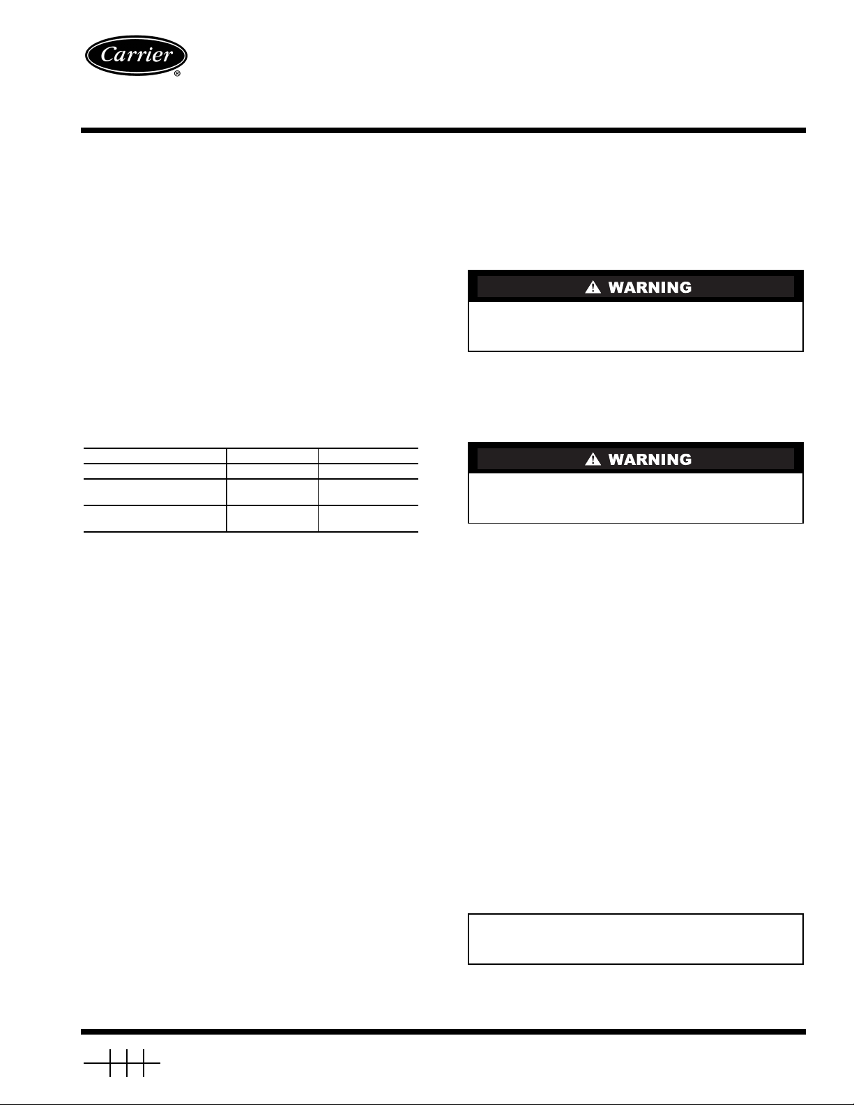
See Fig. 1 for a schematic of the unit piping.
BYPASS LINE — Install the
between the factory-supplied stubs in the discharge line (from
the compressor) and in the liquid line between the expansion
valve and cooler. See Fig. 2.
NOTE: The stubs are sealed as shipped from the factory.
Install the field-supplied shut-off valve in the bypass line as
close to the discharge line as possible. The shut-off valve will
aid in the pumpdown of the low side when closed.
HOT GAS BYPASS VALVE — Install the valve in the bypass
line near the shut-off valve installed in the Bypass Line section
above. The bypass valve has
each), and a
3
/8in. ODM equalizer port (sweat connection). To
ensure proper operation, the valve should be installed in a horizontal section of the bypass line and the pilot valve should be
installed above bypass valve body.
PILOT VALVE AND HOT GAS SOLENOID — Install the
hot gas solenoid onto the pilot valve. The solenoid fits over the
stem of the valve and attaches with the supplied clip on the top
(over the coil).
Install the pilot valve/solenoid assembly in the external
equalizer line of the bypass valve (
The pilot valve has a
3
/8in. ODF inlet and a1/4in. SAE
(Society of Automotive Engineers, U.S.A.) connection to the
TXV (thermostatic expansion valve) equalizer line.
IMPORTANT: Be sure the sweat connection on the hot gas
bypass valve is facing the pilot valve/solenoid assembly in
the equalizer line (See Fig. 1).
5
/8in., field-supplied line
5
/8in. ODF inlet and outlet (one
3
/8in. ODF equalizer port).
Manufacturer reserves the right to discontinue, or change at any time, specifications or designs without notice and without incurring obligations.
Book124
Ta b 3 a 5 c 2 a
PC 111 Catalog No. 533-00067 Printed in U.S.A. Form 30GT/38AKS-1SI Pg 1 1-05 Replaces: 30GT-35SI
Page 2
LEGEND
TXV — Thermostatic Expansion Valve
Factory Piping
Field Piping
5
NOTE: The bypass valve in this package has
connections and can be used directly on 30GT015035 units.
/8in.
Fig. 1 — 30GT Piping Schematic
Fig. 2 — 30GT Stub Locations
DISCHARGE
STUB
(HIDDEN)
LIQUID
STUB
Install the field-supplied
1
/4in. OD tubing from the SAE
connection to the TXV equalizer line. If the connection is made
directly to the TXV, use the field-supplied, 3-way tee with an
internal branch (install horizontally in the line with the internal
branch attaching directly to the TXV). If the connection is
made into the equalizer line, use the field-supplied, standard 3way tee.
Step 2 — Dehydrate and Recharge the Circuit —
replace the filter drier cores. Then evacuate, dehydrate, and recharge the circuit, using approved refrigeration practices.
When piping is completed, leak test the assembly and
Step 3 — Install Control Wiring
Be sure all power to the unit is off before proceeding, and
that all disconnects are open and tagged.
Follow all local codes and NEC (National Electrical Code,
U.S.A.) when installing control wiring. All wire must be a minimum of 16 AWG (American Wire Gage, U.S.A.).
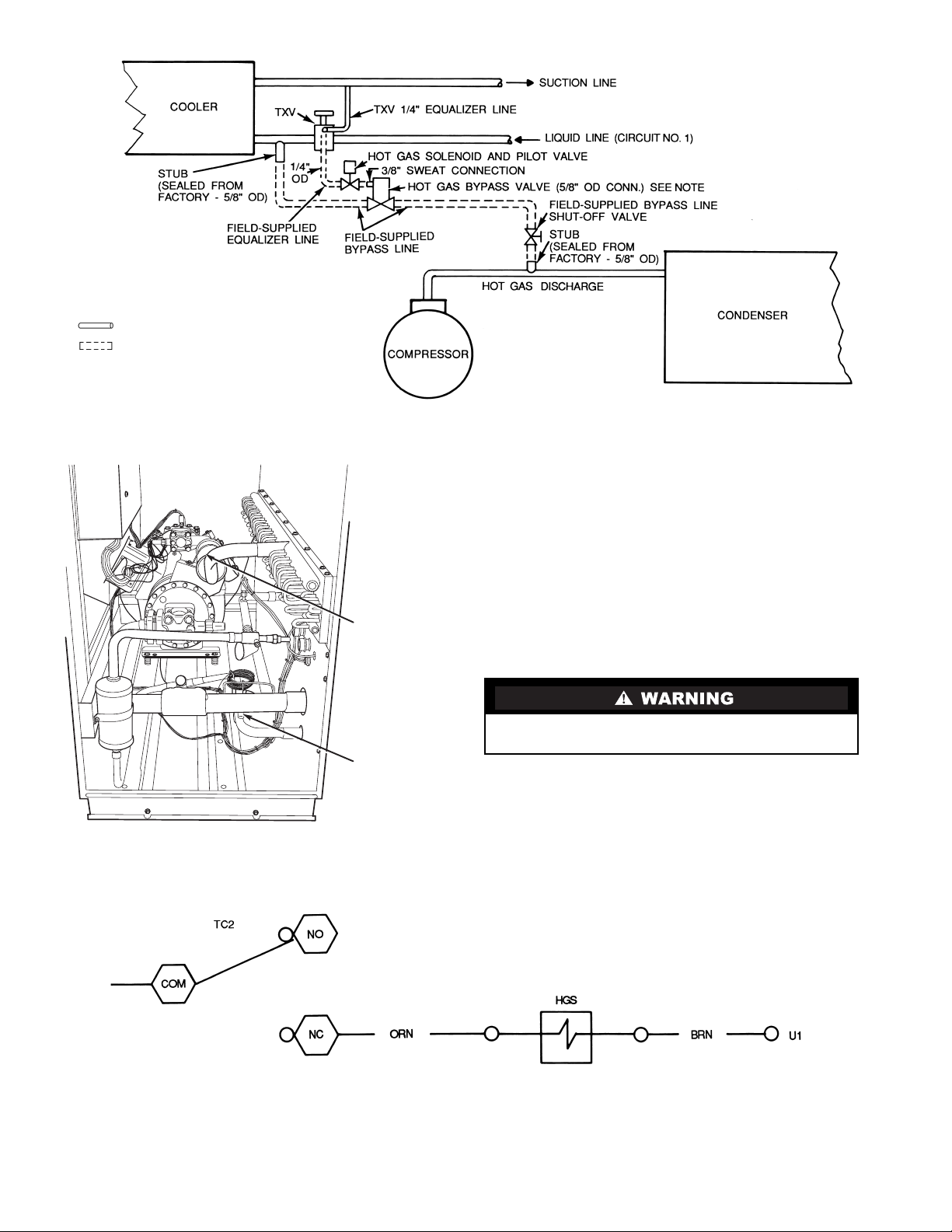
Connect control wires as shown in Fig. 3. At hot gas solenoid (HGS), connect to brown and orange wires as shown.
LEGEND
COM — Common NC — Normally Closed TC — Temperature Controller
HGS — Hot Gas Solenoid NO — Normally Open U1 — Unloader 1
Fig. 3 — 30GT Hot Gas Solenoid Wiring
2
Page 3

INSTALLATION IN 38AKS014-024/INDOOR
FAN COIL (CONSTANT VOLUME)
SPLIT SYSTEM COMBINATION
Step 1 — Install Piping (See Fig. 4)
Shut off all power to the unit and remove refrigerant charge
using an approved refrigerant recovery device before proceeding with installation. Failure to do so may result for
personal injury.
IMPORTANT: Do not bury refrigerant piping underground.
1. In applications where the air handler refrigerant distributor is not equipped with a side outlet connection, it is recommended that a Sporlan in-line auxiliary side connector
with standard distributor be used. Refer to the installation
instructions for the indoor fan coil to obtain nozzle size
and distributor connection size. Select the auxiliary side
connector based on this information. The side connector
must be installed on refrigerant circuit no. 1 (first stage of
cooling) of the fan coil being used.
2. Install a field-supplied
1
/4in. NPT to1/4in. flare fitting on
the gage connection port of the compressor suction
service valve.
3. Sweat the pilot solenoid valve supplied in the hot gas ac-
cessory package directly to the hot gas bypass valve on
3
the
/8in. ODF external equalizer port.
4. Install field-supplied
1
/4in. copper tube (flared with a nut
on each end) between the compressor suction valve and
the hot gas pilot solenoid valve.
5
5. Connect a field-supplied
/8in. OD copper tube between
the discharge line process tube (hot gas stub) and a fieldsupplied manual shutoff service valve, avoiding any traps
in piping.
6. Connect another field-supplied
5
/8in. OD copper tube between the manual shutoff valve outlet and the hot gas bypass valve inlet.
5
7. Connect a field-supplied
/8in. OD copper tube between
the leaving sideof the hot gas bypass valve and theSporlan
auxiliary side connector (distributor-side connector).
LEGEND
TXV — Thermostatic Expansion
*Pilot valve connects directly to
bypass valve per sketch A.
Val ve
Fig. 4 — 38AKS Hot Gas Bypass Piping
3
Page 4

Step 2 — Install Control Wiring (See Fig. 5)
1. Install a field-supplied relay with a 24-v coil and normally closed contacts rated for 20 va at 125 vac inductive
load. Mount this relay in the 38AKS control box.
NOTE: This relay is identified in Fig. 5 as HGR (hot gas
relay).
2. For 38AKS014-024:
a. Connect a field-supplied wire between TB2-3 and
the L1 side of the HGR coil.
b. Connect a field-supplied wire between TB2-9 and
the L2 side of the HGR coil.
c. Connect a field-supplied wire between TB2-2 and
HGR-4, one of the normally closed (NC) contacts.
d. Connect one leg of the hot gas pilot solenoid valve
to HGR-6, the other NC contact.
e. Connect the other leg of the hot gas pilot solenoid
valve to C2.
Step 3 — Restore Refrigerant Charge — Charge
unit in accordance with 38AKS Charging Chart found on unit.
Hot Gas
TB2
9
C2
TC2
TB2
TB2
3
BLU
YEL
LLS
HGR
HGR
ACCESSORY OPERATION AND
ADJUSTMENT
Adjustment — The hot gas bypass valve is set to begin
opening when the suction pressure falls to approximately
62 psig (427 kPa). The pressure corresponds to a chilled water
set point of approximately 44 F (6 C). If the chilled water set
point is lower than 44 F (6 C), the bypass setting must be decreased. The opposite is true if the chilled water setting is
above 44 F (6 C).
Condensing temperature also affects the setting of the bypass
valve, and a change may be required. To adjust the setting of the
bypass valve, a
5
/16in. hex wrench is required. Remove the cap
on the valve, and turn the adjustment nut with the hex wrench.
Turning in a clockwise direction increases the setting, and turning in a counterclockwise direction decreases the setting.
Operation — The hot gas bypass accessory operates as fol-
lows: When a call for cooling is received, the compressor start
circuit is energized, along with the hot gas solenoid (HGS) and
all unloaders. Once the HGS circuit is completed, the solenoid
valve opens allowing the hot gas bypass valve (HGBV) to
sense suction pressure and respond accordingly.
If the suction pressure is below the HGBP (hot gas bypass)
valve setting, the valve begins to open. The valve continues to
open until it either reaches an equilibrium or the maximum
open position. Discharge gas is bypassed into the mixed-phase
line between the expansion valve and the cooler. This condition
continues until the suction pressure rises above the HGBP
valve setting, a second stage of temperature control is called
for, or the unit cycles off.
LEGEND
HGR — Hot Gas Relay
LLS — Liquid Line Solenoid
TB — Te r m i n a l B l o ck
TC — Thermostat Cooling
NOTE: Hot Gas Relay (HGR) use Part No. HN61KK324.
Pilot Solenoid Valve
Fig. 5 — 38AKS014-024 Hot Gas Bypass Wiring
TROUBLESHOOTING
PROBLEM PROBABLE CAUSE SOLUTION
Hot Gas Bypass Valve Fails to Open. 1. Dirt or foreign material in valve.
2. Equalizer passageway clogged.
3. External equalizer not connected or
equalizer line is pinched shut.
Hot Gas Bypass Valve Fails to Close. 1. Dirt or foreign material in valve.
2. Diaphragm failure.
1. Disassemble and clean valve.
2. Disassemble and clean valve.
3. Connect or replace equalizer line.
Check solenoid valve.
1. Disassemble and clean valve.
2. Replace element only.
Copyright 2005 Carrier Corporation
Manufacturer reserves the right to discontinue, or change at any time, specifications or designs without notice and without incurring obligations.
Book124
Ta b 3 a 5 c 2 a
PC 111 Catalog No. 533-00067 Printed in U.S.A. Form 30GT/38AKS-1SI Pg 4 1-05 Replaces: 30GT-35SI
 Loading...