

Page 1
38AK024-044
HEATING A COOLING
Air-Cooled Condensing Units
Installation, Start-Up and Service Instructions
50- and 60-Hertz Air-Cooled Packages
CONTENTS
Page
SAFETY CONSIDERATIONS
BEFORE INSTALLATION
Rigging ...........................................................................l
Placing Unit .................................................................. 3
Mounting Unit
Compressor Mounting
INSTALLATION
Refrigerant Piping Connections ..................................3
Single Pumpout Control
Filter Drier and Moisture Indicator...............................3
Receiver .........................................................................3
Piping Procedure ...........................................................3
Power Supply .................................................................5
Power Wiring..................................................................5
START-UP ................................................................11-16
Initial Check...................................................................11
Leak Test and Dehydration
Preliminary Charge
Start Unit .......................................................................11
...............................................................
..........................................................
......................................................
.........................................
.............................................
.................................................
...............................................
.........................................
1-3
3
3-10
3
11
11
1
3
Charge System .........................................................11
Operation ..................................................................11
Timer Functions ........................................................16
Sequence of Operation.............................................16
Complete Unit Stoppage
SERVICE
Access for Servicing ................................................17
Fan Adjustment ........................................................18
Oil Charge
Liquid Shutoff/Charging Valve
Capacity Control .......................................................18
Oil Pressure Safety Switch (OPS)
Compressor Protection
High-Pressure Switch ..............................................19
Low-Pressure Switch ...............................................19
Winter Start Control
Head Pressure Control
TROUBLESHOOTING .20
..............................................................
.................................................................
.........................................
...............................
............................................
.................................................
............................................
17-19
..........................
Page
16
18
18
19
19
19
19
SAFETY CONSIDERATIONS
Installing, starting up and servicing air conditioning
equipment can be hazardous due to system pressures,
electrical components and equipment location (roofs, ele
vated structures, etc.)
Only trained, qualified installers and service mechanics
should install, start-up and service this equipment (Fig. 1).
Untrained personnel can perform basic maintenance
functions such as cleaning coils. All other operations should
be performed by trained service personnel.
When working on the equipment, observe precautions in
the literature and on tags, stickers and labels attached to the
equipment.
• Follow all safety codes.
• Wear safety glasses and work gloves.
• Keep quenching cloth and fire extinguisher nearby when
brazing.
• Use care in handling, rigging and setting bulky equipment.
• See Table 1 for Physical Data.
ELECTRIC SHOCK HAZARD
Cm
tr
Open all remote disconnects before
servicing this equipment.
BEFORE INSTALLATION
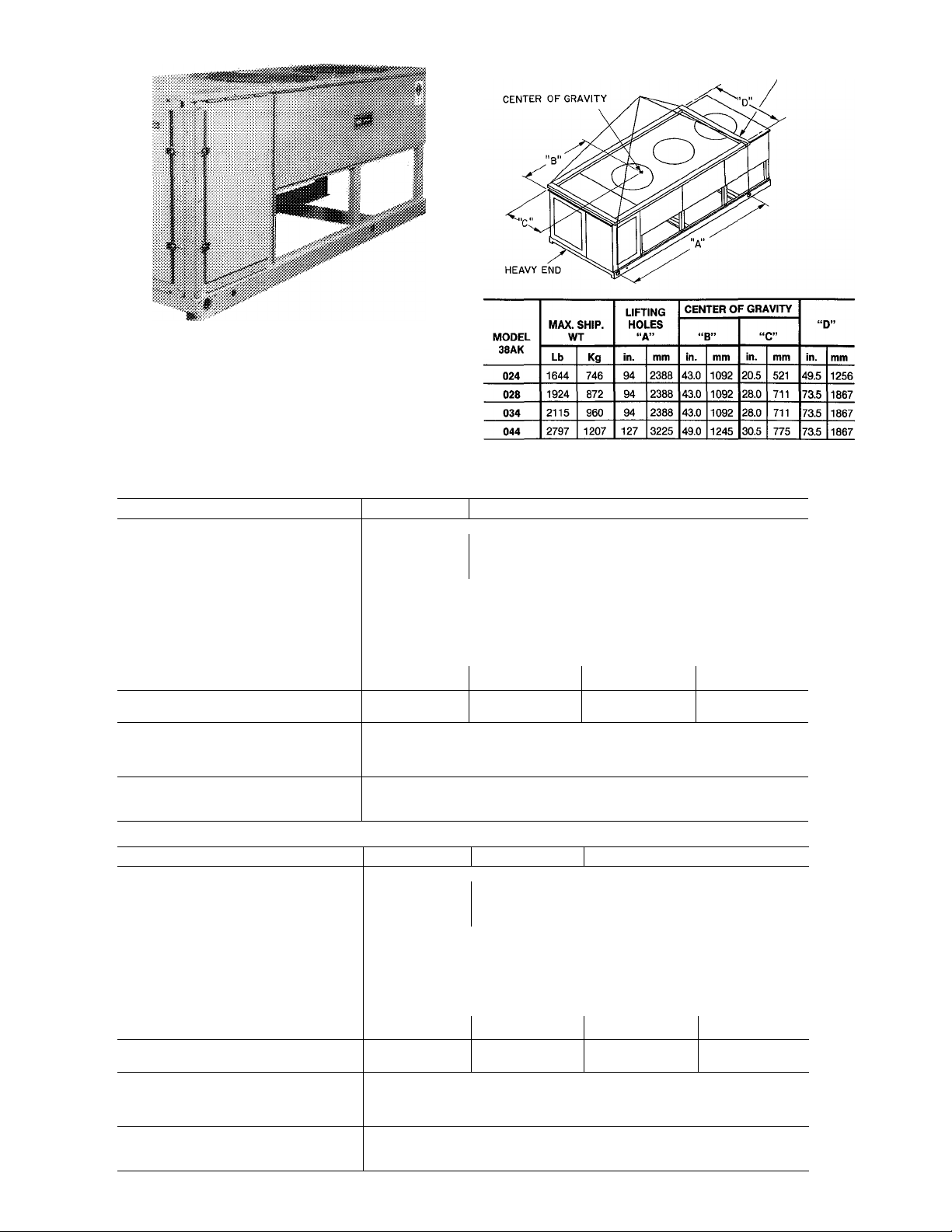
Rigging — Preferred method is with spreader bars
from above the unit. Use 2-in. (50 mm) OD pipe or
hooks in lifting holes. Rig with 4 cables and spreader
bars. All panels must be in place when rigging. See
rigging label on unit for details concerning shipping
weights, distance between lifting holes, center of
gravity and spreader bar dimensions. See Fig. 2.
If overhead rigging is not possible, place chiller on
skid or pad for rolling or dragging. When rolling, use
minimum 3 rollers. When dragging, pull the pad. Do
not apply force to the unit When in final position, raise
from above to lift unit off pad.
A CAUTION
All panels must be in place when rigging. Do not fork
units if no skid is supplied. If unit has skid, truck from
sides only.
Book 1
Tab I 3a
Manufacturer reserves the right to discontinue, or change at any time, specifications or designs without notice and without incurring obiigations.
PC111
Catalog No 563-915
Printed in U S A Form 38AK-1SIM
Pgi
11-89
Replaces: New
Page 2
3/4-IN (19mm) NOTCHES
IN END OR SPREADERS
Fig. 1 - Model 38AK (024 shown)
Fig. 2 — Rigging with Spreader Bars (Field Supplied)
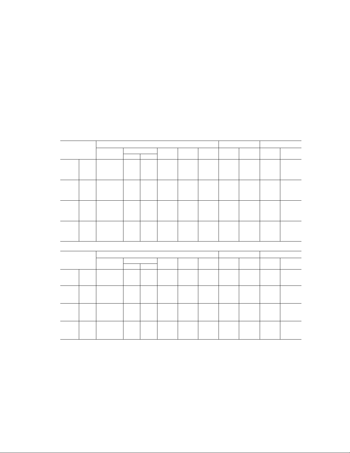
Table 1A — Physical Data — 60 Hertz
UNIT 38AK
COMPRESSOR Reciprocating Semi-Hermetic
No. ...Type 1 06E4250 1 06E9265
No. Cyls (ea) ...Speed, Rpm (r/s) 4 1750(29)
Capacity Steps
Oil Charge*, Pt (L) 14(66)
Oil Pressure Switch Setting (psid)
Crankcase Heater (watts)
Protection See Note
Capacity Control
No. 1
Load
Unload
No. 2
Load
Unload
REFRIGERANT CHG, R-22
Approximate lb (kg)
CONDENSER FANS, Type Propeller Type, Direct Driven
No. ...Diameter, in. (mm)
Total Airflow, Cfm (L/s) 10,600 (5,000) 15,700 (7,400) 23,700(11,200)
Speed, Rpm (r/s) 1140(19)
CONDENSER COIL, Type Horizontal, Plate Fin
Rows...Fins/in. (Fin Spacing mm)
Total Face Area, sq ft (m‘)
024 028 034
1 06E9275
2
6 1750(29)
3
19(9)
180
Suction Pressure Unloader(s)
Unloader Settings (psig)
76
58
—
—
28 (12 7) 305(138)
3 ... 17 (1 49) 2 19(134)
235(218) 39 2(364) 584(543)
76
58
Unloader Settings (psig)
78
60
2 30(762)
76 76
58 58
78 78
60
435(19.7) 65(295)
3 ...30 (762)
3 17(149)
Table IB — Physical Data — 50 Hertz
UNIT 38AK 024
COMPRESSOR
No.... Type 1 06E4250
No. Cyls (ea)... Speed, Rpm (r/s)
Capacity Steps
Oil Charge*, Pt (L)
Oil Pressure Switch Setting (psid)
Crankcase Heater (watts)
Protection
Capacity Control
No. 1
Load
Unload
No. 2
Load
Unload
REFRIGERANT CHG., R-22
Approximate lb (kg)
CONDENSER FANS, Type Propeller Type, Direct Driven
No.... Diameter, in. (mm)
Total Airflow, dm (L/s)
Speed, Rpm (r/s)
CONDENSER COIL, Type Horizontal, Plate Fin
Rows ... Fins/in. (Fin Spacing mm)
Total Face Area, sq ft (m‘)
*See Service, Oil Charge, for Carrier-approved oil
Paid - pounds per sq in differential
4 1450(24 2)
2
14(66)
76
58
—
—
28(12 7)
10,600 (5,000)
3... 17 (149)
235(218) 39.2(364)
NOTE: Circuit breaker in main power circuit and discharge gas thermostat in control circuit
028 034 044
Reciprocating, Semi-Hermetic
1 06E9265 1 06E9275 1 06E9299
Suction Pressure Unloader(s)
Unloader Settings (psig)
76
58
Unloader Settings (psig)
78
60
305(13.8)
2 30 (762) 3... 30 (762)
15,700 (7,400) 23,700 (11,200)
950 (15 8)
2 19(134)
c
180
See Note
6 1450(24 2)
3
19(9)
76 76
58 58
78
60
435(197) 65(295)
3. 17(149)
2
044
1 06E9299
60
78
60
584(543)
Page 3
Placing Unit — There must be 4 ft (1220 mm) for service
and for unrestricted airflow on all sides of unit, and a
minimum of 8 ft (2440 mm) clear air space above unit. For
multiple units, allow 8 ft separation between units for
airflow and service.
Mounting Unit — When unit is in proper location, use of
mounting holes in base rails is recommended for securing
unit to supporting structure, or for mounting unit on
vibration isolators if required. Fasteners for mounting unit
are field supplied. Be sure to mount unit level to ensure
proper oil return to compressors.
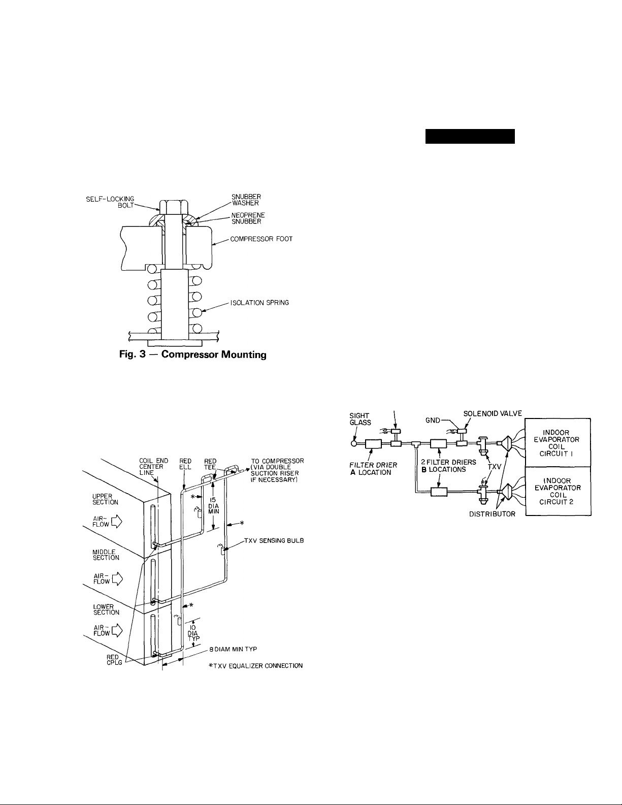
Compressor Mounting — As shipped, compressor is
held down by 4 bolts. After unit is installed loosen each bolt
until the snubber washer can be moved with finger pressure.
See Fig. 3.
Single Pumpout Control — All units are factory wired
to operate on single pumpout control. A factory-supplied
liquid line solenoid valve must be installed in the liquid line
ahead of the indoor coil. See Fig. 5. Wires from solenoid
valve must be in conduit, and a ground wire must be
provided to comply with codes.
A WARNING
Failure to properly install liquid line solenoid at the
indoor unit as described, without Carrier author
ization, may VOID warranty.
If unit is used with a chiller, wiring modifications may be
required.
Filter Drier And Moisture Indicator — Every unit
should have a filter drier and a sight glass (moisture
indicator) field installed. Select the filter drier for maximum
unit Capacity and minimum pressure drop. Figure 5 shows
recommended locations of filter drier(s) and sight glass.
Complete the refrigerant piping from the evaporator to the
condenser before opening the liquid and suction lines at the
condensing unit. One filter drier may be installed at location
A in Fig. 5, or 2 filter driers may be installed at locations B.
INSTALLATION
Refrigerant Piping Connections — Line sizes depend
on length of piping required between condensing unit and
evaporator. See Table 2. It is important to consider liquid
lift and compressor oil return. Refer to Part 3 of Carrier
System Design Manual for line sizing information, and
Fig. 4 for recommended piping details.
NOTES:
1 Suction line is connected to coil on same side as the entering air.
2 For coils having only one section, use upper section piping; for coiis
having 2 sections, use upper and middle section piping
3 Lower section is first on and last off.
4 For more complete piping information, refer to Carrier System
Design Manual, Part 3
Fig. 4 — Suction Line Piping to Unit
with 3 Section Coil Split
FACTORY SUPPLIED
SOLENOID VALVE
FIELD SUPPLIED
CAPACITY CONTROL
Fig. 5 — Liquid Line Solenoid Valve,
Filter Drier(s) and Sight Glass Locations
Receiver — No receiver is provided with the unit; it is
recommended that one not be used.
Piping Procedure — Do not remove run-around pipe
from suction and liquid line stubs until piping connections are
ready to be made. Pass nitrogen or other inert gas through
piping while brazing, to prevent formation of copper oxide.
Install field-supplied thermostatic expansion valve in
liquid line ahead of each evaporator section. For 2-step
cooling, the fleld-supplkd solenoid used must be wired to be
opened by control from a 2-step thermostat
For example: 2 solenoids may be used with 3 TXVs —one
of the solenoids serving a liquid line feeding 2 of the TXVs.
Page 4
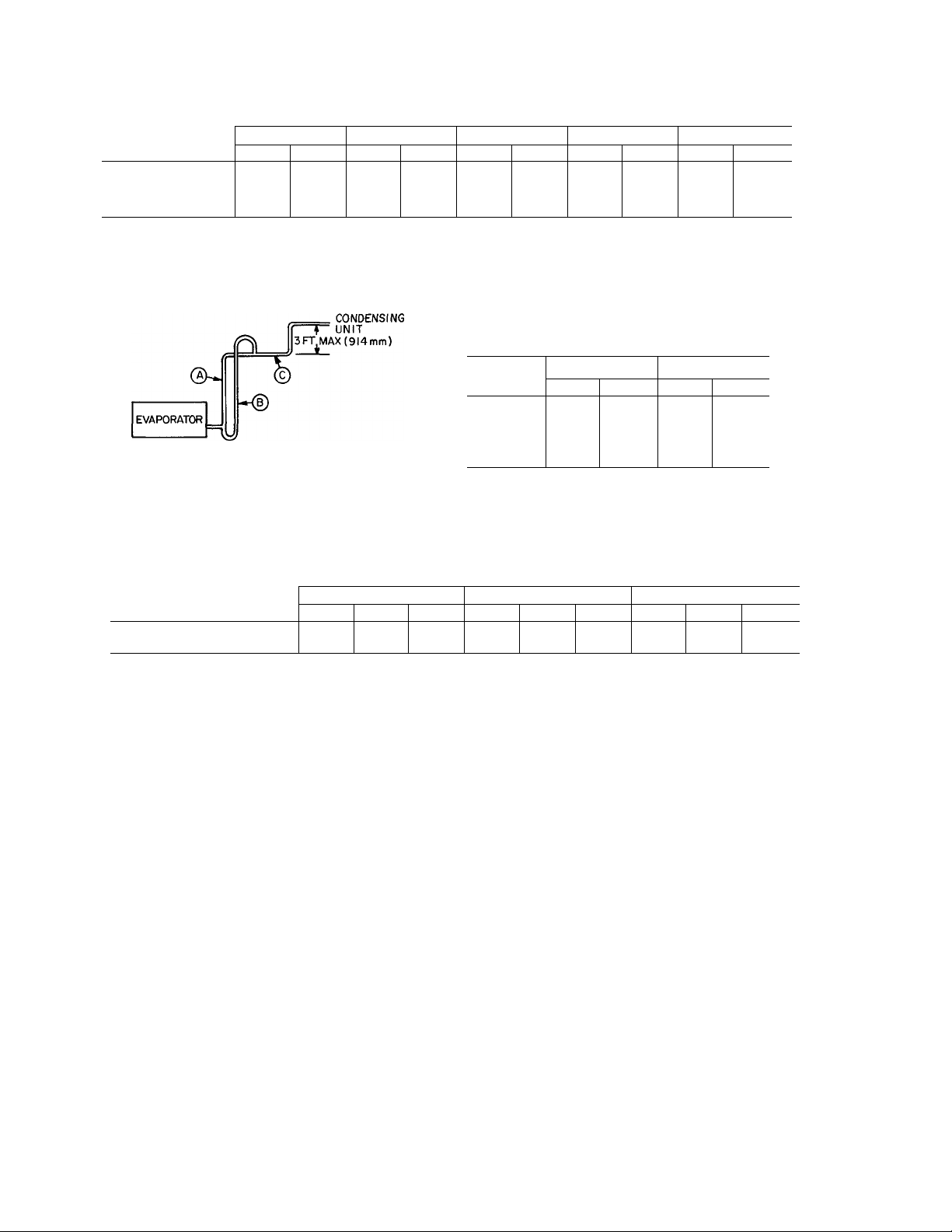
Table 2 — Refrigerant Piping Sizes
SINGLE SUCTION RISERS
MODEL
38AK
024 5/8 1-5/8
028 7/8 1-5/8
034
044
L-Liquid Line S-Suction Line
* IMPORTANT — Requires a double suction riser, see below:
NOTE: Liquid and suction iine sizes are OD (in)
(a) - SUCTION RISER WITHOUT TRAP
(b) - SUCTION RISER WITH TRAP
(^- SUCTION LINE TO CONDENSING UNIT
7/8
7/8
16-25
L
S L S
2-1 /8
2-1/8 7/8 2-1/8
LENGTH OF INTERCONNECTING PIPING (FT)
26-50
7/8 1-5/8
7/8
7/8
2-1 /8 7/8
2-1/8 7/8
DOUBLE SUCTION RISERS
51-75
L
7/8
1-1/8
UNIT 38AK
024 86
028
034 67
044 76
76-100
S
2-1/8 7/8
2-1/8 7/8
2-1/8
*
L
1-1 /8
1-1/8
2-1/8
2-1/8
MAXIMUM LIQUID LIFT
60 Hz 50 Hz
Ft
M
26 72
76
23
20
23
S
*
*
101-200
L S
7/8 2-1/8
7/8 2-1/8
1-1/8
1-1/8
Ft
21
66 20
60
18
66 20
*
*
M
MODEL
38AK
034
044
NOTE: A, B, C dimensions relate to reference diagram
2-1/8
51-75 76-100
A
B C
1-5/8
SUCTION PIPING AT EVAPORATOR AND TXV BULB LOCATION (See Fig. 5)
The purpose of these recommendations is to achieve good
mixing of the refrigerant leaving the evaporator suction
header for proper sensing by the TXV bulb.
1. A minimum of two 90° elbows must be installed
upstream of the expansion valve bulb location.
2. The TXV sensing bulb should be located on a vertical
riser where possible. If a horizontal location is neces
sary, secure the bulb at approximately the 4 o’clock
position.
3. Size the suction line from the evaporator through the
riser for high velocity. Enter the suction pipe sizing charts
in the Carrier System Design Manual at design tons and
equivalent length (for 2 degree F loss). If reading falls
between 2 sizes on chart, choose the smaller pipe size.
LENGTH OF INTERCONNECTING PIPING (FT)
A B C A
2-5/8
1-5/8
1-5/8
2-1/8
2-1/8
2-5/8
2-5/8
1-5/8
1-5/8
Suction piping for the high velocity section should be
selected for about 0.5 degree F friction loss. If a 2 degree
F loss is allowed for the entire suction line, 1.5 degree F
is left for the balance of the suction line and it should be
sized on that basis. Check that the high-velocity sizing is
adequate for oil return up the riser.
If an oil return connection at the bottom of this
suction header is supplied with an evaporator, this
connection must be teed-in ahead of first mixing elbow.
When the compressor is below the evaporator, the riser
at the evaporator does not have to extend as high as the
top level. After a 15-diameter riser has been provided,
the suction line may elbow down immediately.
SAFETY RELIEF — A fusible plug is located on unit
liquid line before the liquid valve.
101-200
B
2-1/8
2-1/8
C
2-5/8
2-5/8
Page 5
Power Supply — Electrical characteristics of available
power supply must agree with unit nameplate rating. Supply
voltage must be within limits shown in Table 3.
IMPORTANT: Operating unit on improper supply
voltage, or with excessive phase imbalance, constitutes
abuse and may affect Carrier warranty. See Unbal
anced 3-Phase Supply Voltage, page 6.
Power Wiring — All power wiring must comply with
applicable local and national codes. Install field-supplied
branch circuit fused disconnect(s) per NEC (National Electri
cal Code) of a type that can be locked OFF or OPEN.
Disconnect(s) must be within sight from and readily acces
sible from unit in compliance with NEC Article 440-14.
Table 3 — Electrical Data
60 HERTZ
MODEL
OfiAtr
024
028
034
044
500
200
600
100
500
200
600
100
500
200
600
100
500
200
600
100
Volts
3 Ph, 60 Hz
208/230
380 342 418 51 1 80 194.9 346 191 3.9
460 414 508
575
208/230
380
460
575 518 632
208/230
380
460
575 518
230
380
460
575
SuDolied*
Min. Max. (Fuse)
187
518 632
187 254
342
414
187
342
414
187 254
342
414
518
UNIT COMPRESSOR
MCA
254 92.1 150 348.6
46.9
42.9 70
124.6 200
418 64.7 110
508 60 7 100 226.1
52.5 80
254
145 5 250
418 72.5 125
508 687 110
632
418
508 91 0 150
632 81.5 125 282.8
54.9 90
2030 350
111 1
50 HERTZ
MODEL
38AK
024
034
044 300
800 230
300 346
900
800
028 300 346
900 400
800 230
300
900
800 230
900
Volts
3 Ph, 50 Hz
400
230
346
400
346
400
Supplied*
Min. Max.
198 254
311
342
198 254 109 175 348.4 76.9 342
311
342
198 254 1202
311
342
198 254
311
342
UNIT
MCA
380 50.5 80
400 49.3 80 1740 347 173 1.0
380 64.9 100
400 605 100 226.0 436 223 30
88.1 125
380 76.1 125
400 68.5
1506 250
380 112.6 175
400 90.8 150 351 0
GENERAL WIRING NOTES
1. A crankcase heater is wired in the control circuit so it is
always operable as long as power supply disconnect is
on, even if any safety device is open or unit stop-start
switch is off. It is protected by a 5-amp circuit breaker in
control power.
2. The power circuit field supply disconnect should never be
open except when unit is being serviced or is to be down for a
prolonged period When operation is resumed crankcase
heater should be energtedfor 24 hours before start-up. If unit
is to be shut down for a prolonged period it is recommended
that the suction arid discharge valves be closed to prevent an
excessive accumulation of refrigerant in the compressor oil
3. Power entry is at one end only.
MOCP
ICF RLA LRA FLA (ea)
68
80 1748
175
MOCP
(Fuse)
123.4
452.2 89.8 446 6.2
250.9 45.5 247 3.9
167.4 36.5 164 3.4
512.2 106.5 506 6.2
283.9 52.6 280
256.1 50 253 3.1
179.4 38.5 176 3.4
702.4
3898 79.5 382 39
351 2 65.4 345 3.1
ICF RLA LRA FLA (ea)
256.4 60.3
2044
34 7
28.9 120 3.4
43.6 223 31
147 5 690
57.1 276 3.4 3
COMPRESSOR
333 200
263.4 44.9
200
110
372.4
2984
2560 50.0 253 3.0
5578 105.1
408.8 79.5
859 366
539 294
65.4
FAN MOTORS!
345
3.6
173 1 8
3.9
62 3
FAN MOTORS!
250
259
545
400
345 30
6.4 2
44 2
64 2
4.4 2
6.4
4.4 2
6.4 3
4.4
Qty
2
2
2
2
2
2
2
2
2
2
2
2
3
3
Qty
2
2
2
2
3
3
FLA — Full Load Amps
ICF — Maximum Instantaneous Current Flow during starting (the
LRA — Locked Rotor Amps
MCA — Minimum Circuit Amps (complies with National Electrical
MOCP — Maximum Overcurrent Protection
RLA — Rated Load Amps
* Units are suitable for use on electrical systems where voltage
supplied to unit terminals is not below or above listed minimum and
maximum limits
t All fans are protected by a single circuit breaker.
point in the starting sequence where the sum of the LRAfor
the starting compressor, plus the total RLA for all running
compressors, plus the total FLA for all running fan motors
is maximum).
Code [NEC], Section 430-24)
Page 6
4. Maximum field wire sizes allowed by lugs on terminal
block are:
350 MCM for models 38AK028 (208/230-3-60),
38AK034 (208/230-3-60, 230-3-50), and
38AK044 (208/230-3-60, 230-3-50)
2/0 AWG for all other models.
5. Terminals for field power supply are suitable for
copper, copper-clad aluminum or aluminum conduc
tors. Insulation must be rated 167 F (75 C) minimum.
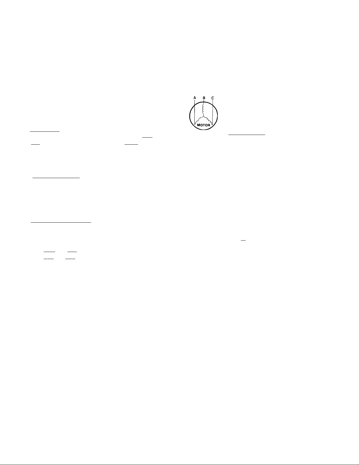
UNBALANCED 3-PHASE SUPPLY VOLTAGE —
Never operate a motor where a phase imbalance in supply
voltage is greater than 2%. Use the following formula to
determine the % voltage imbalance:
% Voltage Imbalance
= 100 X
max voltage deviation from average voltage
average voltage
I ^
CONDENSER FANS — The fans must rotate counter
clockwise when viewed from above. If necessary, correct
direction of fan rotation by interchanging any 2 power
input wires at disconnect switch. Affix crankcase heater
decal (located in installer’s packet) to unit disconnect switch.
FIELD CONNECTIONS
1. Main Power — Bring wires from the fused disconnect
switch through hole in bottom rail of unit to control
box (Fig. 6, 7, 8) and connect terminals 1111, [12
on line side of terminal block TBl (see Fig. 9).
13
To comply with NEC Article 440-14, the disconnect
must be located within sight from and readily acces
sible from unit.
■ 2. 24-v Control Power — Units have single point power
connections. Control circuit is directly connected inter
nally to unit. Maximum 24-v control circuit is 3 amps.
NOTE: For wire runs up to 50 ft. use no. 18 AWG
insulated wire (35 C min.). For 50 to 75 ft., use no. 16
AWG insulated wire (35 C min.). For over 75 ft. use 14
AWG insulated wire (35 C min.).
3. Control Circuit Interlock — An airflow switch may be
installed in the indoor air handler to prevent unit from
running when indoor air is not flowing. This switch (no.
HR81JE001) is available from Service Parts Center, or
equivalent can be field supplied. This should be electri
cally interlocked in the control circuit, between term
inals I 1 I and I 6 I (for flow switch) on TB2. See Fig.
9 for field wiring. This is in the 115-v circuit. Wires must
be run in conduit with ground wire.
4. Transformer Connections — See unit wiring label dia
gram, notes 1 and 2, located behind compressor com
partment end access door.
Example: Supply voltage is 240-3-60.
AB = 243 volts
BC = 236 volts
AC = 238 volts
Average Voltage =
Determine maximum deviation from average voltage:
(AB) 243 - 239 = 4 volts
(BC) 239 - 236 = 3 volts
(AC) 239 - 238 = 1 volt
Maximum deviation is 4 volts. Determine % voltage
imbalance:
% Voltage Imbalance = 100 x —^ = 1.7%
This amount of phase imbalance is satisfactory as it is
below the maximum allowable 2%.
IMPORTANT: Contact your local electric utility
company immediately if the supply voltage phase
imbalance is more than 2%.
243 + 236 + 238 = 239 volts
239
IMPORTANT: Ensure power to the crankcase
heater is always on (except when servicing the unit).
If circuit breakers inside unit shut down the com
pressor and condenser fans, crankcase heater
remains on.
Page 7
NOTES:
1
THERE MUST BE [1220 mm] 4 ft FOR SERVICE AND
FOR UNRESTRICTED AIRFLOW ON ALL SIDES OF UNIT.
THERE MUST BE MINIMUM C2440 mml 8 ft CLEAR
AIR SPACE ABOVE UNIT.
THE APPROXIMATE OPERATING WEIGHT OF THE UNIT IS:
3.
60 HZ
UNIT WT LBS
38AK024
1456 661
38AK024C 1580
NOTE: "C" INDICATES COPPER COIL.
2 4
WT KG
717
50 HZ
UNIT WT LBSWT KG
38AK024
38AK024C 1580
60 Hz
024
024C
50 Hz
024
024c
1456 661
717
APPROX. OPER. WT. (LB.)
AT SUPPORT POINTS
1 2
411
501
448 533
587
433
626
462
245
273 326
486 358
518
HINGED ACCESS DOOR•
CONTROL BOX
3 4
299
382
TOT.
1456
1580
1864
1988
[63.5-92.1] 2 1/2'-:
FIELD MAIN POWER SU
- A
' II
HINGED ACCES
[1315]
4'-3 3/4'
[61]
2 7/16
[19.1]
3/4' dia;
MOUNTING HOLES
(TYP 4 PLACES)
[63.5-92.1]
2 1/2'-3 5/8'DIA.
FIELD POWER
ENTRY 8 LIFTING
[22.2]
7/8' DIA.
FIELD CONTROL
POWER ENTRY
Fig. 6 — Dimensioi
Page 8
ECimON
PAM No. 2
5/8' DIA.
LY
[22.2] 7/8' DIA.
FIELD CONTROL CIRCUIT WIRING
TOP VIEW
1 Drawing, 38AK024
10'-7 13/16'
SIDE VIEW
Page 9

NOTES:
1. THERE MUST BE [1220 mm] 4 Ft FOR SERVICE AND
FOR UNRESTRICTED AIRFLOW ON ALL SIDES OF UNIT.
2. THERE MUST BE MINIMUM [2440 mm] B ft CLEAR
AIR SPACE ABOVE UNIT.
3. THE APPROXIMATE OPERATING WEIGHT OF THE UNIT IS:
60 HZ
UNIT
38AK028
WT LBS
1650
WT KG
748
38AK028C 1804 818
38AK034
1803 818
38AK034C 2009 911
NOTE: “C" INDICATES COPPER COIL.
UNIT WT LBSWT KG
38AK028 1650 748
38AK028C
38AK034 1803
38AK034C
50 HZ
1804
2009
APPROX. OPER. WT. (LB.)
AT SUPPORT POINTS
1
60 Hz
028
028C
034
034C
50 Hz
025
025C
030
030C
2
418
626
462
666
459
673
518
719
590
507
632
542
628
538
683 586
818
818
911
3
242
276
272
323
590
632
628
683
4
364
400
399
449
506
541
538
586
HINGED A(
[22.2] 7/8
FIELD CONTROL CII
[63.5-92.1] 2 1/2'-3
FIELD MAIN POWER I
CONTRC
TOT.
1650
1804
1803
2009
2193
2347
2332
2538
Fig. 7 — Dir
Page 10

ESS DOOR
DIA.
UIT WIRING
8' OIA.
^PLY.
BOX
coMip« secirioN
(FAN No. 1
TOP VIEW
No. 2
FIELD CONTROL
POWER ENTRY
insional Drawing, 38AK028,034
SIDE VIEW
Page 11

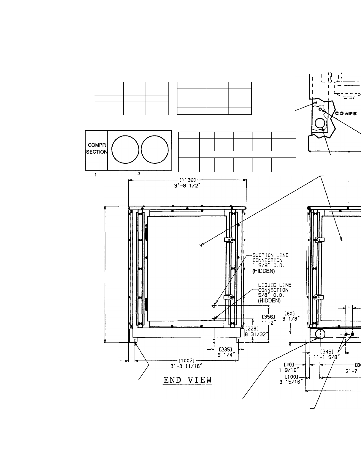
NOTES:
HINGED ACCESS DOOR
1. THERE MUST BE £1220 ram] 4 Ft FOR SERVICE AND
FOR UNRESTRICTED AIRFLOW ON ALL SIDES OF UNIT.
2. THERE MUST BE MINIMUM £2440 mm] 8 ft CLEAR
AIR SPACE ABOVE UNIT.
3. THE APPROXIMATE OPERATING WEIGHT OF THE UNIT IS:
50 HZ 8 60 HZ
UNIT
38AK044
WT LBS
2437
38AK044C 2745
WT KG
1106
1246
CONTROL BOX-
NOTE: “C" INDICATES COPPER COIL.
2 4
APPROX. OPER. WT. (LB.)
AT SUPPORT POINTS
60 Hz
044
044C
1
722
808
2
924
995
3 4
347
422
444
520
TOT.
2437
2745
£1742]
£1315]
4'-3 3/4
FIELD CONTROL CIRCUIT WIRING
£22.2] 7/8' DIA:
£63.5-92.1] 2 1/2'-3 5/8' DIA:
FIELD MAIN POWER SUPPLY
HINGED ACCESS DOOR
SUCTION LINE
CONNECTION
2 1/8' O.D.
(HIDDEN)
LIQUID LINE
CONNECTION
7/8' O.D.
(HIDDEN)
£452]
r-1 9/16'
COOWPR SeCTDOM
£61]-
2 7/16'
£19.1]
3/4' DIA
MOUNTING HOLES
CTYP 4 PLACES)
S'-3 3/4
END VIEW
£63.5--92.1]
■-3 5/8' DIA.
2 1/2
FIELDPOWER
ENTRYa LIFTING
—
£346]
I
r-1 5/8'
•£806] —
2'-7 3/4'
£22.
7/8'
FIEL
POWE
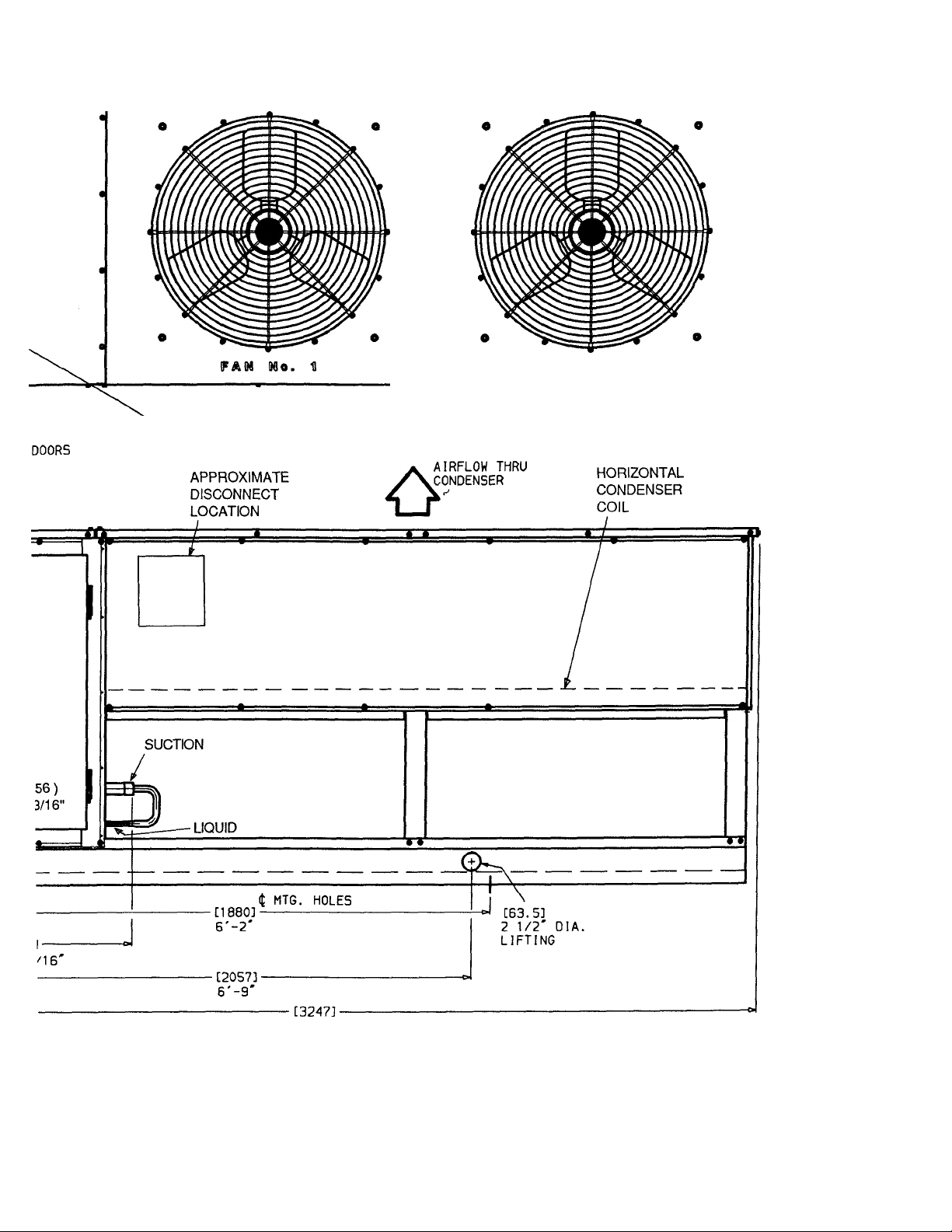
Fig. 8 — Dimensional Dre
Page 12

FAN No. 1
FAN No. 2
TOP VIEW
FAN No. 3
)1A.
CONTROL
ENTRY
ing. 38AK044
SIDE VIEW
Page 13

OR DIA HOLE
[92 I] 3 5/8"
NOTES:
1 Factory wiring in accordance with National Electricai Code (NEC) Any fieid modifications or additions must be in
compliance with aii appiicabie codes
2 AM field interlock contacts in the 115-y control circuit must have minimum rating of 180 va pilot duty pi us capacity required
for field-installed equipment All field interlock contacts in the 24-v control circuit must have minimum ratingof TOvapilot
duty plus capacity required for field-installed equipment Remove wire between terminals TB2-1 and 6 when airflow
switch is field installed
3 For internal unit wiring, reference wiring book TB2 is 115-1-60, TB3 is 24-1-60
LEGEND
AFS — Airflow Switch
GND — Ground
LLSV1 — Liquid Line Solenoid Valve for Pumpout
LLSV2 — Liquid Line Solenoid Valve for Capacity Control
TB — Terminal Block
_——— Field Power Wiring
________
________
Field Control Wiring
Factory Installed Wiring
Fig. 9 — Typical Wiring Schematic
10
Page 14

START-UP
Initial Check
A CAUTION
Do not attempt to start the condensing unit, even mo
mentarily, until the following steps have been com
pleted. Compressor damage may result.
1. Check all auxiliary components such as air handling
equipment, and other equipment. Consult the manu
facturer’s instructions regarding any other equipment
connected to the condensing unit. If used, air flow
switch must be properly installed. See Fig. 9.
2. Backseat (open) compressor suction and discharge
valves. Close valves one turn to allow pressure to reach
test gages.
3. Open liquid line service valve.
4. Set thermostat.
5. Check tightness of all electrical connections.
6. Compressor oil level should be visible in sightglass. See
Service, Oil Charge.
7. Be sure unit is properly leak checked, dehydrated and
charged. See below.
8. Electrical power source must agree with nameplate
rating.
9. Crankcase heater must be firmly locked into compres
sor crankcase. Be sure crankcase is warm (heater should
be on for 24 hours before starting compressor).
10. Be sure compressor floats freely on the mounting
springs. See Compressor Mounting and Fig. 3 for
loosening compressor bolts.
Leak Test and Dehydration — Leak test the entire
refrigerant system by the pressure method described in the
Carrier Service Techniques Manual, Chapter 1, Section 1-6.
Use R-22 at approximately 25 psig backed up with an inert
gas to a total pressure not to exceed 200 psig.
Preliminary Charge — Refer to Carrier Standard
Service Techniques Manual, Chapter 1, Section 1-8 for
charging methods and procedures. Charge system with
approximately 25 lbs of R-22 by the liquid charging method
and charging by weight procedure.
Start Unit — Close field disconnect, fan circuit breaker
and set thermostat above ambient temperature so that there
is no demand for cooling. Now, only the crankcase heater is
energized. After the heater has been on for 24 hours, the unit
can be started. If no time has elapsed since the preliminary
charge step has been completed, it is unnecessary to wait the
24-hour period.
Close the compressor circuit breaker, then reset the
indoor thermostat below ambient temperature, so that a call
for cooling is ensured.
NOTE: Do not use the compressor circuit breaker to start
and stop compressor, except in an emergency.
Depending on the position of the Time Guard timer,
start-up of the compressor occurs within 12 seconds and 8
minutes from the time the control circuit is energized.
Charge System — Actual start-up should be done only
under supervision of a qualified refrigeration mechanic.
Refer to charging charts.
See Fig. 10 through 13 for the particular unit being
charged. Measure pressure at the liquid line service valve,
being sure a Schrader depressure is used if required. Also,
measure liquid line temperature as close to the liquid service
valve as possible. Add charge until the pressure and
temperature conditions of the charging chart curve are met.
If liquid pressure and temperature point fall below curve,
add charge. If liquid pressure and temperature point fall
below curve, reduce the charge until the conditions match
the curve.
A CAUTION
Never charge liquid into the low-pressure side of
system. Do not overcharge. During charging or
removal of refrigerant, be sure indoor fan system is
operating.
Operation — Refer to control circuit diagram on the unit,
or in the unit wiring book.
11
Page 15

LiJ
a
Z3
o
UJ
(C
z>
tE
UJ
Q.
s
UJ
19
BOTH OUTDOOR FANS MUST BE OPERATING
o
LIQUID PRESSURE (PSIG) AT LIQUID VALVE
Fig. 10 — 38AK024 Charging Chart, 50/60 Hz
Page 16

UJ
o
LlJ
OC
Z)
l<
cc
UJ
Q.
UJ
z>
o
BOTH OUTDOOR FANS MUST BE OPERATING
LIQUID PRESSURE (PSIG) AT LIQUID VALVE
Fig. 11 — 38AK028 Charging Chart, 50/60 Hz
Page 17

ijj
%
3
o
<
uT
UJ
cc
3
t-
<
CE
liJ
Q.
LU
t9
3
g
=j
BOTH OUTDOOR FANS MUST BE OPERATING
LIQUID PRESSURE (PSIG) AT LIQUID VALVE
Fig. 12 — 38AK034 Charging Chart. 50/60 Hz
Page 18

UJ
%
a
3
o
UJ
tr
QC
UJ
Q.
s
UJ
3
o
ALL OUTDOOR FANS MUST BE OPERATING
LIQUID PRESSURE (PSIG) AT LIQUID VALVE
Fig. 13 — 38AK044 Charging Chart, 50/60 Hz
Page 19

Timer Functions — (See Fig. 14)
Switch A (contacts A-Al and A-A2) provides Time
1.
Guard® Control Circuit function. Start of compressor
is delayed approximately 5.5 minutes after shut-off.
The minimum time between starts of compressor is 8
minutes.
Switch B (contacts B-Bl and B-B2) starts compressor.
Switch D (contacts D-Dl) bypasses the low-pressure
switch (LPS) for 2.5 minutes at start-up for winter start
control.
(BLACK DENOTES CLOSED CONTACTS) TIMER POSITION DURING
OMIN OR
J.P
_ A-AI
A-AZ*^
® -¡-M f-
— E-El
— D-DI
D-D2
----------------
--------h-—COMPRESSOR STARTS
U— 12 SEC +2 1
-----------------
--
-------
-----
'-H I-
----
5 SEC ±2 1
40 SEC i5
-2-6SEC
150 SEC ±5
1 SEC io.5 1
---------
150 SEC ±5
UNIT OPERATION^
----------------------
M 1
2-6 SEC
-5.5 MIN^A--
Fig. 14 — Timer Cycle
Sequence of Operation — At start-up, the thermostat
calling for cooling and all safety devices satisfied, the control
circuit relay (CRl) closes. The indoor fan motor starts imme
diately. With minimal demand for cooling, only TCI of the
thermostat is made. The timer motor starts and condenser fan
no. 1 starts. Fan no. 2 starts if high side pressure is higher than
260 psig (1793 kPa). Fan no. 3 (38AK044 only) starts if
outdoor ambient rises above 80 F. After a delay by Time
Guard® circuit of 12 seconds to approximately 8 minutes
depending on the timer position, the compressor starts and the
primary liquid line solenoid valve opens.
With only TCI calling for cooling, the capacity control
liquid line solenoid is not energized, therefore the suction
pressure is such that the compressor unloads on suction
pressure shortly after compressor start-up. The compressor
operates at either 1 or 2 steps of unloading depending on the
suction pressure which is, in turn, dependent on the
evaporator load conditions. As cooling demand increases,
TC2 of the 2-stage thermostat energizes the capacity control
liquid line solenoid causing full surface of the evaporator to
be active, tending to raise the suction pressure so that the
compressor loads.
A pump-out relay (FOR) in the control circuit is
energized when thermostat contacts make. A set of normally
open FOR contacts close, completing a compressor control
circuit which bypasses the CRl contacts. As cooling
demand is satisfied, the thermostat contacts break, de
energizing CRl. The LLS valve eloses, stopping the flo\v of
liquid refrigerant to the evaporator and subsequent suction
gas to the compressor. The compressor continues to operate
because of the CRl bypass with relay TRl. With no
refrigerant returning to the compressor, low side pumpout
takes place and the compressor shuts down on lowrpressure
control. The compressor does not restart until the thermo
stat again calls for cooling.
Complete Unit Stoppage
CAUSES — Interruption of supplied power, open discharge
gas thermostat (DGT), compressor overtemperature pro
tection, or open high-pressure safety switeh eauses com
pressor stoppage.
RESTART — The unit recycles and restarts automatically
under the Time Guard® device when power is restored.
Stoppage by DGT, HFS, or compressor circuit breaker
requires manual resetting of the control circuit. To restart
the Time Guard timer when DGT or HFS are tripped,
merely open and then close the thermostat contacts. It is
necessary to manually reset the compressor circuit breaker
at the unit.
If LFS is not closed within 2.5 minutes after compressor
starts, the compressor locks out and the outdoor fans
continue to run. It stays locked out for 5.5 minutes until the
timer motor comes back to 0 time (see Fig. 14). At 0 time, the
LFS is jumpered (winter start control). It remains jumpered
for 2.5 minutes. Because the LFS is jumpered, the com
pressor restarts and runs for the 2.5-minute time period. At
the end of this 2.5 minutes, if the LFS has still not closed, the
compressor is again locked out. The timer motor is de
energized and cannot restart until the LFS closes. The
outdoor fans continue to run as long as there is a call for
cooling. Automatic reset of the LFS causes the timer to
recycle so that the compressor can start.
If sufficient compressor oil pressure has not been built
within 2.5 minutes after the compressor starts, the unit is
completely de-energized until the OFS is manually reset at
the unit.
A CAUTION
If unit or circuit stoppage occurs more than once due
to any safety device, the trouble should be corrected
before any attempt to restart.
16
Page 20

SERVICE
A CAUTION
Turn off all power to unit before proceeding.
OIL PRESSURE SAFETY SWITCH is reset by opening
the side access door on the left side of the unit (as viewed
from the compressor end). The liquid line service valve can
be found behind the side access door on the right-hand side
of the unit (as viewed from the compressor end).
Access for Servicing (See Fig. 15)
COMPRESSOR SECTION — The compressor compart
ment has 2 side doors and one front door for servicing,
providing access to compressor, all components of the
refrigeration system, electrical controls and control box.
After opening front door an inner cover must be removed
for access to control box.
CONDENSER SECTION — Condenser fan motors and
fans can be serviced by removal of outlet grilles or side
panels. If a fan motor is serviced, be sure the wire fan guard
is in place over each fan before starting unit. See Fig. 16 for
proper fan adjustment. Tighten fan hub securely on motor
shaft with setscrew which bears against the key. Be sure to
replace Permagum and rubber cap over end of motor shaft
to protect against moisture causing fan to rust on shaft.
COMPRESSOR END AND RIGHT-SIDE VIEW
OIL
PRESSURE—
SWITCH
COMPRESSOR END, LEFT-SIDE ACCESS DOOR
Fig. 15 — 38AK Unit with Access Panels Removed
COMPRESSOR END, CONTROLS PANEL REMOVED
COMPRESSOR END, RIGHT-SIDE ACCESS DOOR
(38AK024 Shown)
Page 21

Fan Adjustment (See Fig. 16)
TOP OF FAN ORIFICE
ORIFICE
FAN SHAFT
PROP LOCATION
60 Hz
36AK024
38AK028-034
38AK044
50 Hz
38AK024
38AK028,034,044
3.12(79.2)
3.62(91.9) 3.88 (98.6)
3.62(91.9)
3.12(79.2)
FILL HOLE IN FAN HUB
WITH PERMAGUM
“A” in (mm)
Min. Max.
Fig. 16 — Location of Prop on Motor Shaft
from Outside of Orifice Ring
FAN BLADE
HUB PLATE
3.38 (85.9)
3.88 (98.6)
338(85.9)
Liquid Shutoff/Charging Valve is located inside the
compressor compartment and is provided with 1/4-in. flare
connection for field charging.
Capacity Control is by either one or 2 suction pressure
actuated unloaders. Each controls 2 cylinders. Unloaders
are factory set (see Table 1) but may be field adjusted.
Number 1 unloader is on cylinder bank on same side of
compressor as terminal box.
CONTROL SET POINT — The control set point (cylinder
load point) is adjustable from 0 to 85 psig. To adjust, turn
control set point adjustment nut (Fig. 17) clockwise to its
bottom stop. In this position, set point is 85 psig. Then, turn
adjustment counterclockwise to desired control set point.
Every full turn counterclockwise decreases set point by 7.5
psig.
CONTROL
SET POINT
ADJUSTMENT
NUT
Oil Charge — Compressors are factory charged with oil
as follows:
COMPRESSOR
06E4250
06E9265
06E9275
06E9299
AMOUNT
pints (liters)
14(6.6)
19(9.0)
19(9.0)
19(9.0)
When additional oil or a complete charge is required, use
only Carrier-approved compressor oil:
Witco Chemical Corp
.......................................
Suniso 3GS
Texaco, Inc................................................... Capella WF-32
Shrieve Chemical Co
..........................
Zerol 150 (Synthetic)
IMPORTANT: Do not use drained oil or use oil that
has been exposed to atmosphere. Refer to Carrier
Standard Service Techniques Manual, Chapter 1,
Refrigerants, for procedures to add or remove oil.
PRESSURE
DIFFERENTIAL
ADJUSTMENT
SCREW
BYPASS PISTON
DIFFERENTIAL SCREW SEALING CAP
(CAP MUST BE REPLACED
TO PREVENT REFRIGERANT LEAKAGE)
POWER HEAD
VALVE BODY
Fig. 17 — Capacity Control Valve
PRESSURE DIFFERENTIAL—The pressure differenti^
(difference between cylinder load and unload points) is
adjustable from 6 to 22 psig. To adjust, turn pressure
differential adjustment screw (Fig. 17) counterclockwise to
its backstop position. In this position, differential is 6 psig.
Then, turn adjustment clockwise to desired pressure differ
ential. Every full turn clockwise increases differential by 1.5
psig.
18
Page 22

Oil Pressure Safety Switch (OPS) in the control
circuit stops the compressor, and unit, if proper oil pressuré
differential is not established at start-up or maintained
during operation. If OPS stops the unit, determine the cause
and correct before restarting unit. Failure to do so will
constitute abuse. Equipment failure due to abuse may void the
Warranty.
Low-Pressure Switch has fixed, nonadjustable settings.
Switch is mounted on the compressor.
TO CHECK — Slowly close liquid shutoff valve and allow
compressor to pump down. Do not allow compressor to
pump down below 2 psig (13.8 kPa). Compressor should i
shut down when suction pressure drops to cutout pressure in'
Table 4, and should restart when pressure builds up to cut-in
pressure shown.
Compressor Protection
CIRCUIT BREAKER — Calibrated trip manual reset,
ambient compensated, magnetic breaker protects against
motor overload and locked rotor conditions.
DISCHARGE THERMOSTAT — A sensor in the dis
charge gas of 06E compressor reacts to excessively high
discharge gas temperature and shuts off the compressor.
TIME GUARD® control protects compressor against short
cycling. See Sequence of Operation (page 16).
CRANKCASE HEATER minimizes absorption of liquid
refrigerant by oil in crankcase during brief or extended
shutdown periods. Control circuit is maintained if com
pressor fan motor circuit breakers are turned off. Main
disconnect must be on to energize crankcase heater.
IMPORTANT: Never open any switch or disconnect
that de-energizes the crankcase heater unless unit is
being serviced or is to be shut down for a prolonged
period. After a prolonged shutdown on a service job,
energize the crankcase heater for 24 hours before
starting the compressor.
High-Pressure Switch has fixed, nonadjustable set
tings. Switch is mounted on the compressor.
TO CHECK — Open the condenser fan circuit breaker.
Head pressure builds up until compressor shuts down. This
should be at the cutout pressure in Table 4. Close condenser
fan circuit breaker. After pressure drops to cut-in setting,
reset control circuit by opening, then closing the control
circuit switch. After control circuit is reset, the Time Guard
timer cycles and in approximately 5.5 minutes the com
pressor restarts.
Table 4 — Pressure Switch Settings, psig (kPa)
HIGH PRESSURE
Cutout
426 ±7 320 ± 20 27 + 3
(2937 ± 48) (2206 + 138) (186 + 21) (303 + 34)
Cut-in
LOW PRESSURE
Cutout Cut-in
44 + 5
Winter Start Control — Switch D in the 4-function
timer bypasses low-pressure switch for 2(4 minutes on unit
start-up.
Head Pressure Control reduces condensing capacity
under low ambient temperature conditions.
FAN CYCLING — These 38AK units have standard
provision for fully automatic intermediate-season head
pressure control through condenser fan cycling. Fan no. 2 is
cycled by a fan cycling pressure switch (FCPS) which
responds to variation in discharge pressure. The pressure
sensor is located in the liquid line of the refrigerant circuit.
Fan no. 3 cycling is controlled by outdoor air temperature
through an air temperature switch (ATS) (38AK044 units
only).
The ATS is located in the lower divider panel between the ,
compressor compartment and condenser section. Through i
a hole in the panel, the sensing element is exposed to air
entering the no. 1 fan compartment. Fan no. 1 is non
cycling. Table 5 shows the operating settings of the fan
cycling pressure switch and the air temperature switch.
Table 5 — Fan Cycling Controls
CONTROL BY SWITCH OPENS
Temp, F (C)
Pressure,
psig (kPa)
NOTE: See Fig. 6, 7, 8 for fan arrangement
70 + 3(21 +1.7) 80 + 3 (27 + 1.7)
160 + 10(1103 + 69)
SWITCH CLOSES
260+ 15(1793 + 103)
19
Page 23

TROUBLESHOOTING
SYMPTOM AND PROBABLE CAUSE
COMPRESSOR DOES NOT RUN
1. Power line open
2. Oil pressure switch tripped
3. Safety device tripped
4. Contactor stuck open
5. Loose terminal connection
6. Improperly wired controls
7. Seized compressor
8. Low line voltage
9. Compressor motor defective
COMPRESSOR STOPS ON LOW-PRESSURE
CONTROL
1. Compressor suction shutoff valve partially closed
2. Low refrigerant charge
3. Liquid line solenoid valve(s) fails to open
COMPRESSOR STOPS ON HIGH-PRESSURE
CONTROL
1. Compressor discharge valve partially closed
2. Air in system
3. Condenser fan(s) not operating
UNIT OPERATES TOO LONG OR CONTINUOUSLY
1. Low refrigerant charge
2. Control contacts fused
3. Air in system
4. Partially plugged expansion valve or filter drier
PROBABLE REMEDY
1. Reset circuit breaker
2. Reset oil pressure switch at unit
3. Reset control circuit with thermostat
4. Replace contactor
5. Check connections
6. Check and rewire
7. Check motor winding for open or short. Replace
compressor, if necessary
8. Check line voltage — determine location of
voltage drop and remedy deficiency
9. Check motor winding for open or short. Replace
compressor, if necessary
1. Open valve
2. Add refrigerant
3. Check liquid line solenoid valve for proper operation.
Replace if necessary
1. Open valve or replace if defective
2. Purge and evacuate system
3. Check motor wiring and repair or replace if defective
1. Add refrigerant
2. Replace control
3. Purge and evacuate system
4. Clean or replace
SYSTEM IS NOISY
1. Piping vibration
2. Compressor noisy
COMPRESSOR LOSES OIL
1. Leak in system
2. Crankcrase heaters not energized during shutdown
3. Inadequate piping
FROSTED SUCTION LINE
1. Expansion valve admitting excess refrigerant
HOT LIQUID LINE
1. Shortage of refrigerant due to leak
2. Expansion valve opens too wide
FROSTED LIQUID LINE
1. Restricted filter drier
COMPRESSOR WILL NOT UNLOAD
1. Defective unloader
2. Defective capacity control solenoid valve
3. Miswired liquid line solenoid
4. Weak, broken or wrong valve body spring
COMPRESSOR WILL NOT LOAD
1. Miswired capacity control liquid solenoid
2. Defective capacity control solenoid valve
3. Plugged strainer (high side)
4. Stuck or damaged unloader piston or piston ring(s)
1. Support piping as required
2. Check valve plates for valve noise. Replace
compressor if bearings are worn
1. Repair leak
2. Check wiring and relays. Check heater and replace
if defective
3. Check piping for oil return. Replace if necessary
1. Adjust expansion valve
1. Repair leak and recharge
2. Adjust expansion valve
1. Remove restriction or replace
1. Replace
2. Replace valve
3. Rewire correctly
4. Replace spring
1. Rewire correctly
2. Replace valve
3. Clean or replace strainer
4. Clean or replace the necessary parts
20
Page 24

Book 1
Tab
1
3a
Manufacturer reserves the right to discontinue, or change at any time, specifications or designs without notice and without incurring obligations.
PC111
Catalog No 563-915 Printed in U S A Form 38AK-1SIM Pg21 11-89
Replaces: New
V.
 Loading...