

Page 1
38AK007
HEATING & COOLING
Installation, Start-Up and Service
Instructions
SAFETY COIMSIDERATIONS
Installing and servicing air-conditioning equipment can
be hazardous due to system pressure and electrical compo
nents. Only trained and qualified service personnel should
install or service air-conditioning equipment.
When working on air-conditioning equipment, observe
precautions in literature and on tags and labels attached to
unit.
Follow all safety codes. Wear safety glasses and work
gloves. Use quenching cloth for brazing operations. Have
fire extinguisher available. Read these instructions thor
oughly. Consult local building codes and National Electri
cal Code (NEC) for special installation requirements.
A WARNING
Before installing or servicing system, always turn off
main power to system. There may be more than one
disconnect switch. Electrical shock can cause personal
injury.
Air-Cooled Condensing Unit
INSTALLATION
Step 1 — Complete Pre-Installation Checks
UNCRATE UNIT — Remove unit packaging except for
the top skid assembly and wood bumpers, which should be
left in place until after unit is rigged into place.
INSPECT SHIPMENT — File claim with shipping com
pany if shipment is damaged or incomplete.
CONSIDER SYSTEM REQUIREMENTS
• Consult local building codes and NEC for special instal
lation requirements.
• Allow sufficient space for airflow clearance, wiring,
refrigerant piping, and servicing unit. See Eig. 1 and
Table 1.
• Locate unit so that condenser airflow is unrestricted on
all sides and above. Refer to Fig. 1.
• Unit may be mounted on a level pad directly on base
rails or mounted on raised pads at support points. See
Table 2 for weight distribution based on recommended
support points.
NOTE: If vibration isolators are required for a particular in
stallation, use data in Table 2 to make proper selection.
Table 1 — Physical Data
UNIT 38AK
OPER WEIGHT (lb)
REFRIGERANT*
COMPRESSOR
on (oz) 65
CONDENSER AIR FAN
Number...Rpm 60 Hz
Diameter (in.)
Motor Hp (NEMA)
Nominal Cfm Total
CONDENSER COIL
Face Area (sq ft)
Storage Capacity (lb)t
CONNECTIONS (sweat)
Suction (in.)
Liquid (In.)
CONTROLS
Pressurestat Settings
High Cutout
Low Cutout
FUSIBLE PLUG 200 F
‘Unit is factory supplied with holding charge only.
fStorage capacity of condenser coil with coil 80% full of liquid R-22
at 124 F
50 Hz
Cut-in
Cut-in
Propeller; Direct Drive
007
340
22
1.. .850
1.. 708
26
Vs
3800
12 24
11.264
1V8
V2
426 ± 7 psig
320 ± 20 psig
7 ± 3 psig
22 ± 5 psig
Manufacturer reserves the right to discontinue, or change at any time, specifications or designs without notice and without incurring obligations.
Book|1 |4 PC 111 Catalog No 633-809 Printed in U.S A Form 38AK-2SI Pg 1 6-92 Replaces: New
Tab 3a 2a
Page 2
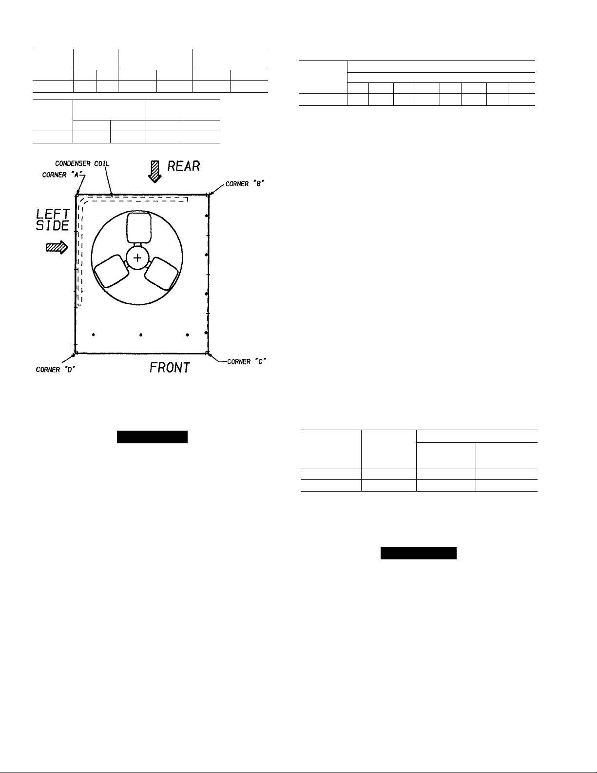
Table 2 — Weight Distribution
STD. UNIT
UNIT
38AK007
UNIT
38AK007 77
WEIGHT
lbs.
340
CORNER WEIGHT
lbs.
CORNER WEIGHT
lbs.
kg.
154
(C)
86
kg.
35
(A)
CORNER WEIGHT
kg. lbs.
39 53
CORNER WEIGHT
(D)
lbs. kg.
124 56
(B)
kg.
24
REFRIGERANT PIPING SIZES
EQUIVALENT LENGTH OF PIPING - FT
IVe V2
76-100
s
IVs
COND
UNIT
38AK007
L — Liquid Line S — Suction Line
NOTES:
1. Pipe sizes are based on a 2° F loss for liquid and suction lines
2. Pipe sizes are based on an equivalent length equal to the max
imum length of interconnecting piping plus 50 percent for fittings.
3. Charge units with R-22 in accordance with unit installation
instructions.
0-25 26-50 51-75
Line Size (in. OD)
L
V2 IVs
L s L s L
s
IVa
V2
Va
SIZE REFRIGERANT LINES - Consider length of pip
ing required between condensing unit and evaporator, amount
of liquid lift, and compressor oil return. See Table 3 and
also refer to Part 3 of Carrier System Design Manual for
design details and line sizing. Refer to evaporator installa
tion instructions for additional information.
INSTALL FILTER DRIER AND MOISTURE INDICA
TOR — The filter drier is factory supplied and field in
stalled. Moisture indicator is a field-installed option and should
be installed just after liquid line shutoff valve. Do not use a
receiver; there is none provided with unit and one should
not be used.
NOTE: Unit is shipped with R-22 holding charge. System
pressure must be relieved before removing caps.
Pass nitrogen or other inert gas through piping while braz
ing to prevent formation of copper oxide.
Install field-supplied thermostatic expansion valve to evap
orator section. It is recommended that a field supplied liq
uid line solenoid be positioned in the main liquid line close
to the evaporator coil, and wired to close when compressor
stops to minimize refrigerant migration during the “OFF”
cycle.
Step 2 - Rig and Mount the Unit
ik CAUtlON
Be sure unit panels are securely in place prior to
rigging.
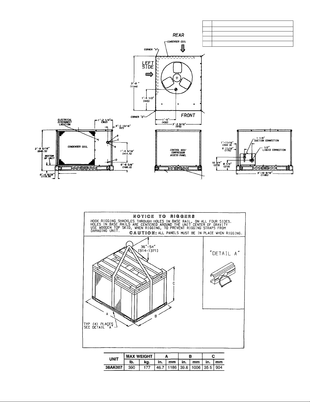
RIGGING — These units are designed for overhead rig
ging. Refer to rigging label for preferred rigging method.
Spreader bars are not required if top crating is left on unit.
All panels must be in place when rigging. (See Fig. 2) As
further protection for coil faces, plywood sheets may be
placed against sides of unit, behind cables. Run cables to a
central suspension point so that angle from the horizontal is
not less than 45 degrees. Raise and set unit down carefully.
If it is necessary to roll unit into position, mount unit on
rails, using a minimum of 3 rollers. Apply force to rails,
not unit. If unit is to be skidded into position, place it on a
large pad and drag it by the pad. Do not apply any force to
unit.
Raise from above to lift unit from rails or pad when unit
is in final position.
After unit is in position, remove all shipping wrapping
and top crating.
Step 3 — Complete Refrigerant Piping Connec
tions — Suction connection is 1-1/8-in. sweat with plas
tic cap; liquid connection is 1/2-in. sweat with plastic cap.
Follow standard piping practices.
Table 3 — Liquid Line Data
MAX
UNIT 38AK007
60 Hz
50 Hz
NOTE: Values shown are for units operating at 45 F saturated suc
tion and 95 F entering air
ALLOWABLE
LIQUID
LIFT (ft)
86 7
72
Max Allowable
Pressure Drop
LIQUID LINE
(psi)
7
Max Allowable
Temp Loss
(F)
2
2
Step 4 — Make Electrical Connections
A WARNING
Unit cabinet must have an uninterrupted, unbroken elec
trical ground to minimize the possibility of personal in
jury if an electrical fault should occur. This ground may
consist of electrical wire connected to unit ground lug
in control compartment, or conduit approved for elec
trical ground when installed in accordance with NEC
ANSI (American National Standards Institute)/NFPA
(National Fire Protection Association) 70-1987 and lo
cal electrical codes. Failure to follow this warning could
result in the installer being liable for personal injury of
others.
Page 3
NOTES:
1. Dimensions in are in miiiimeters.
Center of gravity.
3
4 Minimum ciearance (locai codes or jurisdiction may
5. With the exception of the clearance for the condenser
6 Units may be installed on combustible floors made from
Direction of air fiow.
prevaii):
a Bottom to combustibie surfaces 0 in.
b Condenser coil, for proper air flow, 36 in. one side,
12 in the other The side getting the greater ciear
ance is optionai
c Overhead, 60 in to assure proper condenser fan op
eration.
d Between units, controi box side, 42 in per NEC.
e Between unit and ungrounded surfaces, control box
side, 36 in per NEC
f Between unit and block or concrete walls and other
grounded surfaces, control box side, 42 in per NEC
coil as stated in notes 5a, b, and c, a removable fence
or barricade requires no clearance
wood or class A, B, or C roof covering material
A 1%” DIA. [35] FIELD POWER SUPPLY HOLE
CONNECTION SIZES
B 2” DIA. [51] POWER SUPPLY KNOCK-OUT
c 2V2'’ dia [64] POWER SUPPLY KNOCK-OUT
Ve" DIA [22] FIELD CONTROL WIRING HOLE
D
rxp ÍKMSr
► -0'-2 9/16
LEFT SIDE
-3’-S 3/IS"
Fig. 1 -
FORIC TRUX SLOTS
<3 SlOeS ÚM.W
u 3'-3 1/2'
0003}
-------------------
FRONT
Dimensions (ft-in.)
0*-2 Ì/4'DJA Í57J
(TYP 0 PLACES)
RIGHT SIDE
Fig. 2 - Rigging Label
Page 4

FIELD POWER SUPPLY - All units except 208/230-v
units are factory wired for the voltage shown on the name
plate. If the 208/230-v unit is to be connected to a 208-v
power supply, the transformer must be rewired by moving
the black wire from the 230-v orange wire on the trans
former and connecting it to the 200-v red wire from the
transformer. The end of the orange wire must then be
insulated.
Refer to unit label diagram for additional information.
Pigtails are provided for field wire connections. Use
factory-supplied splices or UL (Underwriters’ Laborato
ries) approved copper/aluminum connector.
When installing units, provide a disconnect per NEC.
All field wiring must comply with NEC and local
requirements.
Install field wiring as follows;
1. Install conduit through side panel openings.
2. Install power lines to connections as shown in Fig. 3.
Wrap connections with electrical tape.
Voltage to compressor terminals during operation must
be within voltage range indicated on unit nameplate (also
see Table 4). On 3-phase units, voltages between phases
must be balanced within 2% and the current within 10%.
Use the formula shown in Table 4, Note 2, to determine the
% voltage imbalance. Operation on improper line voltage
or excessive phase imbalance constitutes abuse and may cause
damage to electrical components. Such operation would in
validate any applicable Carrier warranty.
LEGEND
C — Contactor
NEC — National Electrical Code
----------
Field Wiring
Factory Wiring
Splice Connection
(Factory Supplied)
Fig. 3 — Power Wiring Connections
Table 4 — Electrical Data
UNIT
NOMINAL VOLTAGE
(V-Ph-Hz)
208/230-3-60
460-3-60
38AK007 575-3-60
220-3-50
400-3-50
LEGEND
CSA
FLA
HACR
LRA
MCA
MOCP
NEC
OFM
RLA
NOTES:
1 In compliance with NEC requirements for multimotor and combi
nation load equipment (refer to NEC Articles 430 and 440), the
overcurrent protective device for the unit shall be fuse or HACR
breaker.
2. Unbalanced 3-Phase Supply Voltage
Never operate a motor where a phase imbalance in supply volt
age is greater than 2%. Use the following formula to determine
the % voltage imbalance.
= 100 X
Canadian Standards Association
Full Load Amps
Heating, Air Conditioning and Refrigeration
Locked Rotor Amps
Minimum Circuit Amps
Maximum Overcurrent Protection
National Electrical Code
Outdoor (Condenser) Fan Motor
Rated Load Amps
max voltage deviation from average voltage
---------------------------------------------------------
average voltage
-----------------------------------
VOLTAGE RANGE COMPR OFM
MIN MAX
187 254 19.0 142 1.9 25 6 351
414 508
518
198 242
360 440
RLA LRA FLA MCA MOCP
9.5 72
632 76 58 1.9
19.0 142
9.5 72
Example: Supply voltage is 460-3-60.
AB = 452 V
BC = 464 V
AC = 455 V
Average Voltage =
NOTE: The 575-v units are CSA only.
(AB) 457 - 452 = 5 V
(BC) 464 - 457 = 7 V
(AC) 457 - 455 = 2 V
Maximum deviation is 7 v.
Determine % voltage imbalance
% Voltage Imbalance = 100 x — = 1 53%
This amount of phase imbalance is satisfactory as it is below the
maximum allowable 2%.
1 0 12.9
1.9
1.0 129
POWER SUPPLY
11.4 15.2
25.6 35.1
452 -H 464 -H 455
1371
7
457
17.6
17.6
3
^ 457
IMPORTANT: If the supply voltage phase imbalance is more
than 2%, contact your local electric utility company immedi
ately.
Page 5

FIELD CONTROL WIRING — Install a Carrier-approved
accessory thermostat assembly according to installation in
structions included with the accessory. Locate thermostat
assembly on a solid wall in the conditioned space to sense
average temperature in accordance with thermostat instal
lation instructions.
Route thermostat cable or equivalent single leads of col
ored wire from subbase terminals to low-voltage connec
tions on unit (shown in Fig. 4) as described in Steps 1 through
3 below.
NOTE: For wire runs up to 50 ft, use no. 18 AWG (Amer
ican Wire Gage) insulated wire (35 C minimum). For 50 to
75 ft, use no. 16 AWG insulated wire (35 C minimum).
For over 75 ft, use no. 14 AWG insulated wire (35 C min
imum). All wire larger than no. 18 AWG cannot be directly
connected to the thermostat and will require a junction box
and splice at the thermostat.
1. Connect thermostat wires to screw terminals of lowvoltage connection board.
2. Pass the control wires through the hole provided in the
comer post.
3. Feed wire through the raceway built into the comer post
to the 24-v barrier located on the left side of the control
box. See Fig. 5. The raceway provides the UL required
clearance
between the high- and low-voltage
wiring.
THERMOSTAT CONNECTIONS
THERMOSTAT
WIRING CONNECTIONS
FOR STANDARD UNIT
UNIT CONNECTION
BOARD
Fig. 4 — Control Wiring Connections
START-UP
Preliminary Checks
1. Check that all internal wiring connections are tight and
that all barriers, covers, and panels are in place.
2. Field electrical power source must agree with unit name
plate rating.
3. All service valves must be open.
Leak Test — Test entire refrigerant system by using soap
bubbles and/or an electronic leak detector.
Evacuate and Dehydrate — Evacuate and dehy
drate entire refrigerant system by use of the methods de
scribed in GTAC II, Module 4, System Dehydration.
Refrigerant Charge — Refer to GTAC II, Module 5,
Charging Recovery, Recycling and Reclamation.
Unit panels must be in place when unit is operating dur
ing charging procedure.
Unit is shipped with holding charge only. Weigh in 7 lbs
R-22 to start unit.
NO CHARGE — Use standard evacuating techniques. Af
ter evacuating system, weigh in the specified amount of re
frigerant. (Refer to Table 1.)
LOW CHARGE COOLING - Use Cooling Charging Chart,
Fig. 6. Vary refrigerant until the conditions of the chart are
met. Note the charging chart is different from type nor
mally used. Chart is based on charging the units to the cor
rect subcooling for the various operating conditions. Accu
rate pressure gage and temperature sensing device are required.
Connect the pressure gage to the service port on the liquid
line service valve. Mount the temperature sensing device
on the liquid line, close to the liquid line service valve and
insulate it so that outdoor ambient temperature does not af
fect the reading. Indoor-air cfm must be within the normal
operating range of the unit.
Operate unit and adjust charge to conform with charging
chart, using liquid pressure and temperature to read chart.
TO USE COOLING CHARGING CHART - Initially charge
with 7 lbs. R-22. Place pressure gage at liquid line service
valve. Install thermocouple to liquid line near the liquid line
service valve. Operate unit. Plot liquid pressure and tem
perature on chart and add or reduce charge to meet curve.
HOLE IN
END PANEL
(HIDDEN)
Fig. 5 - Field Control Wiring Raceway
CHARGING CHART - 38AK007
OUTDOOR FAN MUST BE OPERATIN0
Q.
g
uj
>
/
Q
1
<
p
< 90-
tt
UJ
1
2
5
o
AC
Ì » 1 F AG5^
/
:
UR№
7
/
i
2
2
/
/
« XX£
:h
UMe IF« .iU
a
Ì
UOUiO
0 2
PRESSURE
h 0 r
s
LIQUID
0 25
0 31
VALVE (PS
0 3!
IG)
0 400
Fig. 6 — Cooling Charging Chart — 38AK007
ve
i
Page 6

Unit Preparation — Make sure that unit has been in
stalled in accordance with installation instructions and ap
plicable codes.
Compressor Mounting — Compressors are inter
nally spring mounted. Do not loosen or remove compressor
holddown bolts.
Internal Wiring — Check all electrical connections in
unit control boxes; tighten as required.
Time Guard II® Device — Time Guard II Circuit pro
vides for a delay of approximately 5 minutes before restart
ing compressor after shutdown from safety device action.
On start-up, the Time Guard timer causes a delay of ap
proximately 15 seconds after thermostat closes.
Refrigerant Service Ports — Each unit system may
have Schrader type service ports: one on the suction line,
one on the liquid line, and one on the compressor discharge
line. Be sure that caps on the ports are tight.
Cooling — Set space thermostat to OFF position. Set sys
tem selector switch at COOL position and fan switch at AUTO,
position. Adjust thermostat to a setting below room tem
perature. Compressor starts on closure of contactor.
Check cooling effects at a setting below room tempera
ture. Check unit charge. Refer to Refrigerant Charge sec
tion on page 5.
Reset thermostat at a position above room temperature.
Compressor will shut off.
SERVICE
A CAUTION
When servicing unit, shut off all electrical power to
unit to avoid shock hazard or injury from rotating parts.
Cleaning — Inspect unit interior at the beginning of each
cooling season and as operating conditions require.
CONDENSER COIL — Inspect coil monthly. Clean con
denser coil annually and as required by location or outdoorair conditions.
Clean coil as follows:
1. Turn off unit power.
2. Remove top panel screws on condensing unit.
3. Remove condenser coil comer post. See Fig. 7. To hold
top panel open, place coil comer post between top panel
and side panel. See Fig. 8.
CONTROL BOX
CORNER POST
TO SHUT OFF UNIT - Set system selector switch at OFF
position. Resetting thermostat at a position above room tem
perature shuts unit off temporarily until space temperature
exceeds thermostat setting. Units are equipped with CycleLOC™ protection device. Unit shuts down on any safety
trip and remains off; an indicator light on thermostat comes
on. Check reason for safety trip.
Compressor restart is accomplished by manual reset at
the thermostat by turning the selector switch to OFF posi
tion and then to ON position.
Sequence of Operation — At start-up, the thermo
stat calls for cooling, and with all safety devices satisfied,
the compressor contactor and fan contactor will energize,
causing the compressor and outdoor-fan motor to operate.
Contacts on TBl terminals 1 and 2 are also energized, al
lowing the field supplied and installed indoor-fan contactor
to function. A field supplied and installed liquid line valve
(connect to TB1 terminals 3 and 4) will also open, allowing
the system to function in cooling. As cooling demand is
satisfied, the thermostat contacts break, deenergizing the
contactor causing the system to shut off. The liquid line
shutoff valve closes minimizing the potential for refrigerant
migration at this time. The compressor does not restart un
til the thermostat again calls for cooling. If a demand for
cooling occurs within 5 minutes after the thermostat is sat
isfied, the system will not restart due to the feature of Time
Guard®II. After the 5 minute time period, the system will
restart as normal upon thermostat demand. The system is
protected with Cycle-Loc device so that the compressor will
not start if a high-pressure or low-pressure fault occurs. Merely
turn down the thermostat to eliminate the cooling demand
to reset the Cycle-Loc device. This should be done only
once, and if system shuts down due to the same fault, de
termine the problem before attempting to reset the CycleLoc device. The 38AK007 unit does not require a crank
case heater.
Fig. 7 — Cleaning Condenser Coil
Page 7

TOP VIEW
4. Remove device holding coil sections together at return
end of condenser coil. Carefully separate the outer coil
section 3 to 4 in. from the inner coil section. See
Fig. 9.
5. Use a water hose or other suitable equipment to flush
down between the 2 coil sections to remove dirt and de
bris. Clean the outer surfaces with a stiff brush in the
normal manner.
6. Reposition the outer coil section, and remove the coil
comer post from between the top panel and side panel.
Secure the sections together. Install the coil comer post
and replace all screws.
Condenser-Fan Adjustment (Fig. lO)
1. Shut off unit power supply.
2. Remove condenser-fan assembly (grille, motor, motor
cover, and fan).
3. Loosen fan hub setscrews.
4. Adjust fan height as shown in Fig. 10.
5. Tighten setscrews.
6. Replace condenser-fan assembly.
MOTOR COVER OUTLET GRILLE
Fig. 10 — Condenser-Fan Adjustment
Lubrication
COMPRESSORS — Each compressor is charged with cor
rect amount of oil at the factory.
FAN MOTOR BEARINGS — Fan motor bearings are of
the permanently lubricated type. No further lubrication is
required.
Page 8

TROUBLESHOOTING GUIDE
COMPRESSOR DOES NOT RUN
Contactor Open
Power off — restore power.
Fuses blown — replace with correct fuses after finding cause
and correcting.
Transformer dead — replace transformer if primary wind
ings are receiving power.
Thermostat circuit open — check thermostat setting.
Low-pressure switch open — check for refrigerant under
charge or obstruction of indoor airflow.
High-pressure switch open — check for refrigerant over
charge or obstruction of outdoor airflow.
Connections loose — tighten all connections.
Compressor motor thermostat open — check for excessive
motor temperature.
Contactor Closed
Compressor leads loose — check connections.
Single phasing — replace blown fuse.
COMPRESSOR CYCLES ON
HIGH-PRESSURE SWITCH
Condenser Fan On
High-pressure switch faulty — replace switch.
Airflow restricted — remove obstruction.
Air recirculating — clear airflow area.
Noncondensables in system — purge and recharge as re
quired.
Refrigerant overcharge — purge as required.
Refrigerant system restrictions — check or replace filter
drier, expansion valve, etc.
Condenser Fan Off
Fan slips on shaft — tighten fan hub setscrews.
Motor not running — check power and capacitor.
Motor bearings stuck — replace bearings.
Motor overload open — check overload rating. Check for
fan blade obstruction.
Motor burned out — replace motor.
COMPRESSOR CYCLES ON
LOW-PRESSURE SWITCH
Evaporator Air Fan Running
Filter drier plugged — replace filter drier.
Expansion valve power head defective — replace power
head.
Low refrigerant charge — add charge. Check low-pressure
switch setting.
Airflow Restricted
Evaporator coil iced up — check refrigerant charge.
Evaporator coil dirty — clean coil fins.
Indoor air filter dirty — clean or replace filters.
Indoor air dampers closed — check damper operation and
position.
Evaporator Air Fan Stopped
Electrical connections loose — tighten all connections.
Fan relay defective — replace relay.
Motor overload open — check power supply.
Motor defective — replace motor.
Fan belt broken or slipping — replace or tighten belt.
COMPRESSOR RUNS BUT
COOLING INSUFFICIENT
Suction Pressure Low
Refrigerant charge low — check charge.
Head pressure low — check refrigerant charge.
Indoor-air filters dirty — clean or replace filters.
Expansion valve power head defective — replace power
head.
Evaporator coil partially iced — check low-pressure
setting.
Evaporator airflow restricted — remove obstruction.
Suction Pressure High
Heat load excessive — check for open doors or windows.
Copyright 1992 Carrier Corporation
Manufacturer reserves the right to discontinue, or change at any time, specifications or designs without notice and without incurring obligations.
Book|1 |4 PC 111 Catalog No 533-809 Printed in U S A Form 38AK-2SI Pg 8 6-92 Replaces: New
Tab 3a 2a
 Loading...