

Page 1
38AK,38AKS,38AQS008-012
48/50H J,48/50TJ,50LJQ008-014
Accessory Low Ambient Operation
Motormaster® III Control Package
Installation Instructions
Part Numbers: CAMOTOR3001AOO, CAMOTOR3002A00
50/60 Hz
CONTENTS
Page
SAFETY CONSIDERATIONS
GENERAL
..............................................................
...................................
1
1,2
INSTALLATION......................................................2-16
Step 1 — Install Motor .............................................2
Step 2 — Install Motormaster III
Controller
..............................................................
3
Step 3 — Install Sensor ...........................................3
Step 4 — Make Electrical Connections
.................
6
Step 5 — Install Field-Fabricated
Wind Baffies and Brackets
..................................
6
Step 6 — Restore Power to Unit..............................6
TROUBLESHOOTING
..........................................
17
SAFETY CONSIDERATIONS
Installation, start-up, and servicing of this equipment
can be hazardous due to system pressures, electrical com
ponents, and equipment location (roofs, elevated struc
tures, etc.)-
Only trained, qualified installers and service technicians
should install, start up, and service this equipment.
When working on this equipment, observe precautions in
the literature and on tags, stickers, and labels attached to
the equipment and any other safety precautions that may
apply.
A WARNING
Open all remote disconnects before servicing this equip
ment. Electrical shock could result in personal injury.
GENERAL
This book contains instructions for the installation,
start-up, and service of the Motormaster III control on
38AKS008-012, 38AQS008, 38AK008-012, 48/50TJ008-
014, 48/50HJ008-014, and 50LJQ008,012 units. The
Motormaster III control is not used on 50-Hz versions of
the 50HJ008-014 and 50LJQ008,012 units.
NOTE: The Motormaster III control is not used on 48/50HJ
and 48/50TJ units with 2 condenser fans. The control is
used on single condensing fan units only.
The Motormaster III accessory is UL (Underwriters’ Lab
oratories) and CSA (Canadian Standards Association)
approved on all split system and small rooftop electric cool
ing and gas heating/electric cooling units.
The Motormaster III device is a motor speed control de
vice which adjusts condenser fan motor speed in response
to declining liquid temperatures. A properly applied Motormaster III control extends the operating range of air condi
tioning systems and permits operation at lower outdoor am
bient temperatures.
Table 1 shows the ambient temperature in cooling at which
each unit will operate without modification.
Table 1 — Unit Ambient Temperature Operation
UNIT
Small Rooftop Units
All 100%
Split System Units
38AQS008 (60 Hz) 100%
38AK/AKS008
(50/60 Hz)
38AKS009 (60 Hz) 100%
38AKS009 (50 Hz) 100% 90 (32) 57 (14)
38AKS012*
(50/60 Hz)
38AK012
(50/60 Hz)
* Unit has one step of unloading.
COMPRESSOR
CAPACITY
100%
100%
67%
100%
CONDENSER
TEMP
F(C)
90 (32)
90 (32)
90 (32)
90 (32) 53 (12)
90 (32)
80 (27)
90 (32)
MINIMUM
OUTDOOR
TEMP
F(C)
25 (--1)
55 (13)
60 (15)
48 (9)
52 (11)
52 (11)
To operate the units below the ambient temperatures in
Table 1, wind baffles and the Motormaster III control pack
age must be added. The Motormaster III control permits
operation of the unit to an ambient temperature of -20 F
(-29 C) for small rooftop units, and 0 F (-18 C) for split
system units.
The Motormaster III regulates the speed of 3-phase fan
motors which are compatible with the control. These
motors are included in the package. See Tables 2 and 3 for
the contents of the Motormaster III accessory packages.
The CAMOTOR3001A00 package contains a motor for
208/230 volt, 60 Hz and 220 volt, 50 Hz applications. The
CAMOTOR3002A00 package contains a motor for 460
and 575 volt, 60 Hz and 400 volt, 50 Hz applications. See
Fig. 1.
Manufacturer reserves the right to discontinue, or change at any time, specifications or designs without notice and without incurring obiigations.
Book|1 |1 |1 |1 |4 |4 |4 |4 PC 111 Catalog No 533-803 Printed in U S A. Form 38/48/50-4SI Pg 1 1-95 Replaces: New
Tab la 1b 3a 5a 2a 5a 6a 6b
Page 2
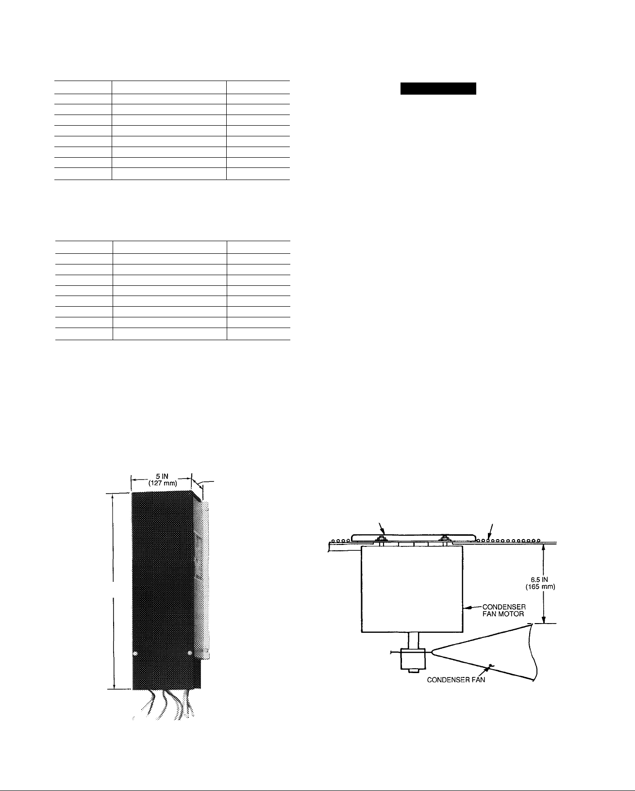
Table 2 - Motormaster® III Control Package
CAMOTOR3001A00, 208/230 v, 60 Hz and 220 v,
50 Hz Applications
INSTALLATION
Step 1 — Install Motor
QUANTITY
1 Motormaster III Control HR46GN001
1
1
8 Screw (5/16-In.)
1 Relay
2
1 Bracket 50DK507132
1 Socket HY07RB030
Sensor 30GT412176
Motor
Screw (no. 6 — 20 X 3/4-ln )
ITEM
PART NO.
HD52GK208
AL81AS216
HN61KZ024
AL56AU128
Table 3 — Motormaster III Control Package
CAMOTOR3002A00, 460 and 575 v, 60 Hz and
400 V, 50 Hz Applications
QUANTITY ITEM
1
1 Sensor
1
8
1 Relay
2 Screw (no. 6 — 20 X 3/4-in.)
1
1 Socket
Motormaster III Control
Motor HD52GK460
Screw (5/16-in )
Bracket
PART NO.
HR46GN001
30GT412176
AL81AS216
HN61KZ024
AL56AU128
50DK507132
HY07RB030
Before Installing — inspect the contents of the acces
sory package before installing. File a claim with the ship
per if shipping damage is found. Contact the Carrier dis
tributor if a part is missing.
3 1/4 IN.
(83 mm)
A WARNING
To avoid the possibility of electrical shock, open all
disconnects before installing or servicing this
accessory.
1. Shut off unit power supply.
2. Remove unit access panel and control box cover.
3. Disconnect fan motor connection in control box and
remove motor leads from control box.
4. Remove condenser fan assembly (grille, motor, motor
cover, and fan) by removing the 6 grille holddown screws.
5. Loosen fan hub set screws and remove condenser fan
from motor shaft.
6. Carefully lift off motor cover.
7. Remove the 4 holddown nuts that attach the motor to
the grille. Pull the motor wires through the grille
conduit.
8. Cut back the steel conduit on the grille (one grille wire
width) to allow adequate space for new fan motor.
9. Feed the Motormaster III motor wires through the con
duit and install motor from accessory kit onto grille us
ing nuts from Step 7.
10. Replace the motor cover on the grille using the square
cutouts.
11. Replace condenser fan on motor shaft.
12. Adjust fan height as shown in Fig. 2.
13. Tighten set screws on fan hub to 7 ft-lbs (9.52 N-m
[newton-meters]) ± 1 ft-lb (1.5 N-m).
NOTE: On 48HJ009 and 48HJ/TJ014 units, perform Step 2
— Install the Motormaster III Controller through Step 4 —
Make Electrical Connections, before reinstalling the con
denser fan. Motormaster III installation is done through the
condenser fan opening with the fan and motor removed.
14. Reinstall condenser fan assembly onto unit using screws
from Step 4. Torque to 20 in.-lbs (2260 mN-m)
± 2 in.-lbs (226 mN-m).
15. Pull motor wires completely through conduit.
16 IN
(406 mm)
MOUNTING
BASE
/
Fig. 1 — Motormaster III Control
MOTOR COVER OUTLET GRILLE
Fig. 2 — Condenser Fan Height Adjustment
Page 3
Step 2 — Install Motormaster® III Controller
1. Configure the control signal selection switch. Remove
the cover of the Motormaster III control. Set the switch
on the Motormaster III control board (underneath cover)
to accept the thermistor (sensor) input signal. Set the
frequency switch to match the unit power supply (50 Hz
or 60 Hz). See Fig. 3 for switch locations and proper
position. Replace the cover.
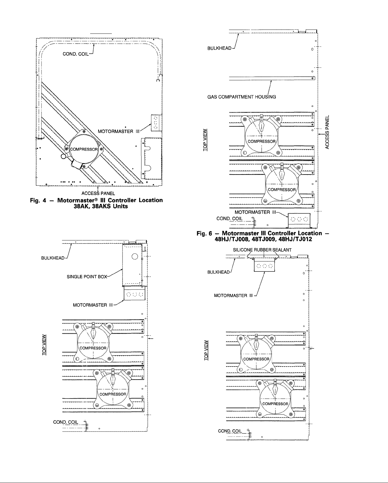
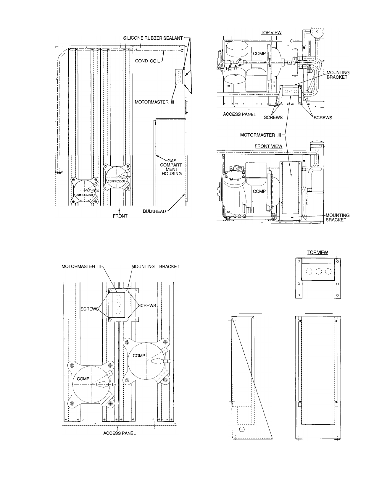
2. 38AK008.012; 38AKS008-012; 48HJ008,012; 48TJ008012; 50HJ/TJ008-014; AND 50UQ008,012; UNITS WITH
SINGLE POINT BOX: Mount the Motormaster III con
troller on the unit in the location specified in Fig. 4-6.
The controller must be mounted vertically with the leads
at the bottom. Using the template provided on the last
page of the book, mark the 4 mounting hole locations.
Mount the controller using the Yie-in. self-drilling screws
provided.
A CAUTION
To avoid damaging components and wiring, use ex
treme care when drilling screw holes and screwing
in fasteners.
50HJ/TJ008-014 AND 50LJQ008,012 UNITS WITH
OUT SINGLE POINT BOX; 48HJ009 (208/230
AND 460 V); AND 48HJ/TJ014 UNITS: Mount the
Motormaster III controller on the unit in the location spec
ified in Pig. 7 and 8. The controller must be mounted
vertically with the leads at the bottom. Using the tem
plate supplied on the last page of the manual, mark the
4 mounting locations. Mount the controller using the
yi6-in. self-drilling screws provided. To prevent any
water leakage though the bulkhead (the partition sepa
rating the indoor and outdoor sections), an electric
component compatible, general purpose silicon rubber
sealant must be used along the 4 edges of the controller
and at the 4 mounting-screw locations.
38AQS008 AND 48HJ009 (575 V) UNITS: The
Motormaster III controller must be mounted on a sheet
metal bracket provided. Mount the bracket on the unit
in the location specified in Fig. 9 and 10 using four
yi6-in. self-drilling screws provided. If needed, a bracket
mounting template is provided on page 21. The control
ler must be mounted vertically, with the leads at the
bottom. Mount the controller on the bracket using the
remaining four 5/16-in. self-drilling screws. See Fig. 11
for controller mounting details.
Step 3 — Install Sensor
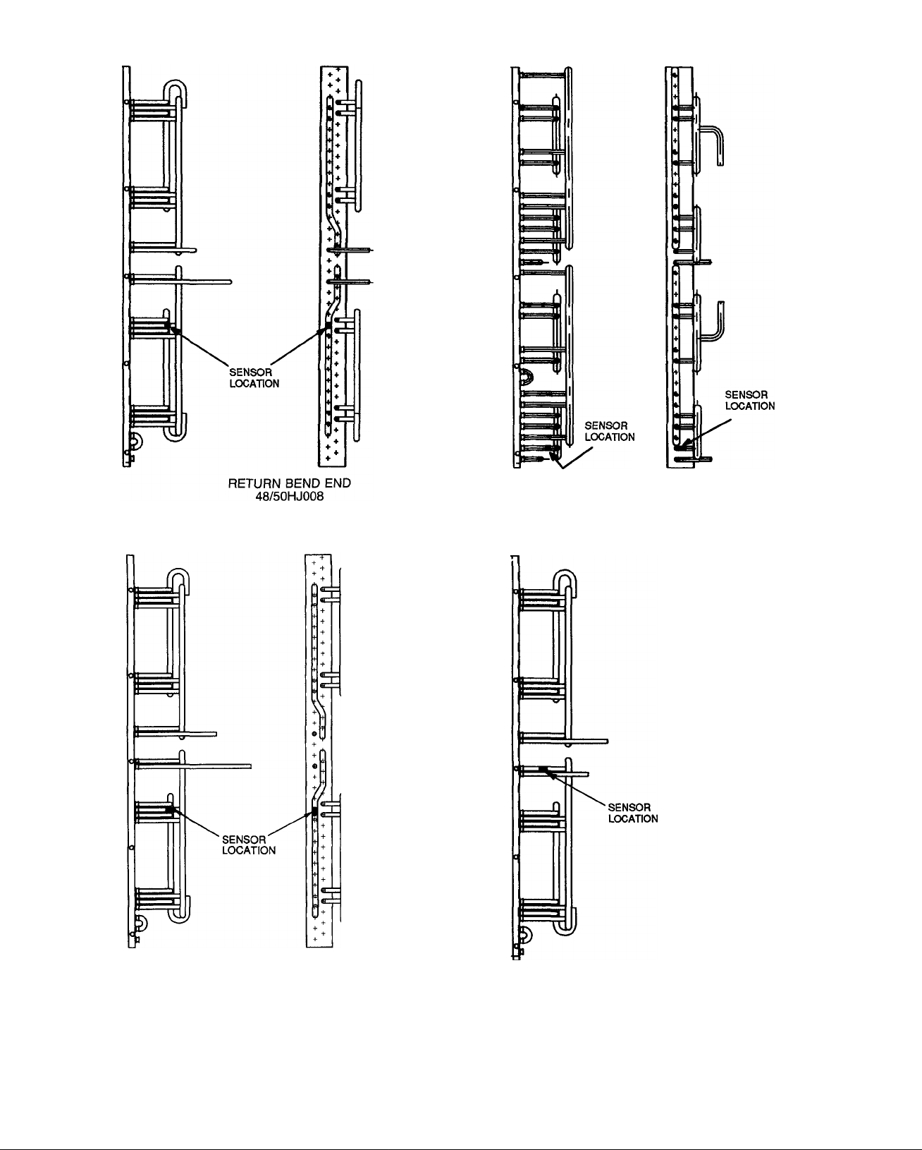
38AK008,012; 38AKS008-012 AND 48/50HJ,TJ008-014
UNITS — Install the sensor for thermistor input control on
the header tube designated in Fig. 12. Connect the sensor
leads to the violet and gray control signal leads on the
Motormaster III controller. Wrap and tie excess sensor wir
ing. Refer to Step 4 — Make Electrical Connections and
the unit wiring diagram for more information on wiring the
sensor.
A CAUTION
I Sensor assembly is delicate. Handle with care. |
38AQS008 AND 50LJQ008,012 UNITS - Wiring is fieldsupplied. Wiring must be 16 AWG (American Wire Gage)
(1.5 mm^), appliance wiring material, rated 75 C or its equiv
alent, with %4-in. (.8 mm) minimum insulation thickness.
All wiring must comply with NEC (National Electrical Code)
and applicable local codes.
50 HZ
,(o^
60 HZ
CONTROL INPUT
___
(SENSOR) THERMISTOR* 4 - 20 mA
GND — Ground
*For thermistor (sensor) signal, move switch to the left.
NOTE: Thermistor is designated in text as “sensor.”
PHASE SEQUENCE
INDICATOR
ADJUST SWITCH
TO MATCH LINE
FREQUENCY
ADJUST SWITCH TO
\ MATCH INPUT
k CONTROL SIGNAL
CE]
__________
LEGEND
Fig. 3 — Motormaster III Control Signal Selection Switch
□
LH izzi
□
LEADS TO POWER
SOURCE
LEADS TO
MOTOR
3 HOLES 0 88 DIA (FOR 1/2 IN CONDUIT)-
BLACK LI
BLUEL3 YELL2
GRN (GND)
CONTROL
SIGNAL
LEADS
+VIO
-GRAY
Page 4
TOP VIEW
Fig. 5 — Motormaster III Controller Location
50HJ,50LJQ,50TJ008-014
(With Single Point Box)
-CO
UJ
z
<
a.
CO
LU
o
o
<
-CO
Lil
Z
<
0.
CO
iii
o
o
<
K
Fig. 7 - Motormaster III Controller Location -
50HJ, 50LJQ, 50TJ008-014 (Without Single Point Box)
Page 5
TOP VIEW
Fig. 8 — Motormaster® III Controller Location —
48HJJJ014, All Voltages; 48HJ009, 208/230,
460-3-60 Only
TOP VIEW
Fig. 10 — Motormaster III Controller Location —
38AQS008
SIDE VIEW
FRONT VIEW
Fig. 9 — Motormaster III Controller Location
48HJ009 (575 V)
Fig. 11 — Motormaster Hi Controller Mounting
Page 6

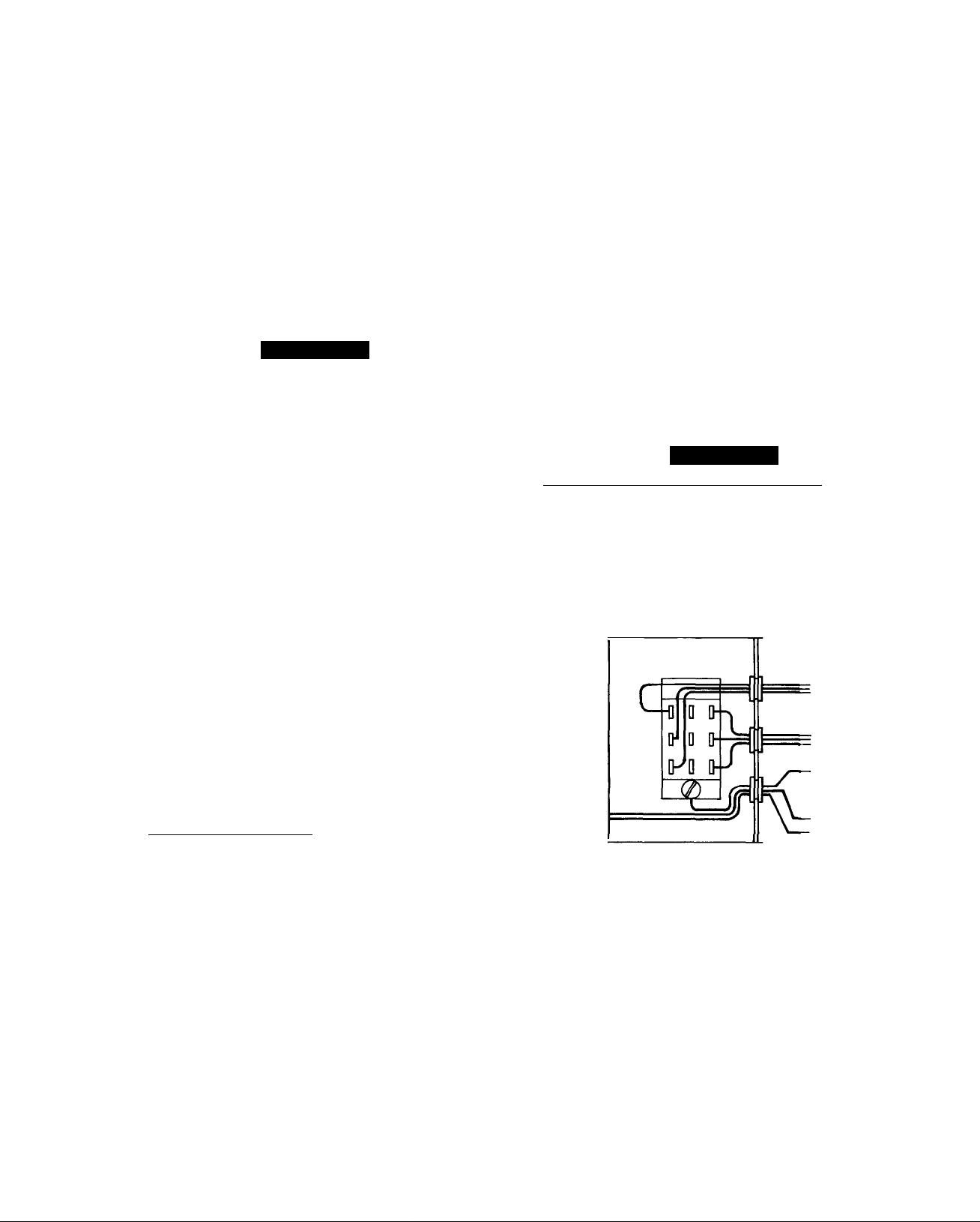
Install the sensor for thermistor input control on the header
tube designated in Fig. 13 and 14. Insert relay into socket.
Install the Motormaster® III relay in the unit control box,
in the location specified in Fig. 15 and 16. Use the two
no. 6-20 X 3/4-in. screws provided.
Connect one sensor lead to the violet control signal lead
on the Motormaster III controller and to a field-supplied
16 AWG wire with a wirenut. Connect the remaining
sensor lead to the gray control sensor lead on the
Motormaster III controller and to another field-supplied
16 AWG wire with a wirenut.
Route both field-supplied wires through a factorypunched access hole under the control box. Attach the wires
to screw terminals 1 and 9 on the Motormaster III relay in
the control box. Wrap and tie excess sensor wiring. Wrap
wirenuts with waterproof tape to prevent them from loos
ening and to ensure watertightness. Refer to Step 4 - Make
Electrical Connections and the unit wiring diagram for more
information on wiring the sensor.
A CAUTION
Sensor assembly is delicate. Handle with care.
Step 4 — Make Electrical Connections
A WARNING
To avoid possibility of electrical shock and personal
injury, turn off all power to unit before making elec
trical connections. Tag all disconnects to alert others
not to turn on power until work is completed.
The wires necessary for wiring the Motormaster III con
trol to the unit must be field-supplied. Use 16 AWG (Amer
ican Wire Gage) (1.5 mm^) appliance material wire, with
2/64-in. (.8 mm) minimum insulation thickness. Use 75 C
type or equivalent. All wiring must comply with NEC
(National Electrical Code) and applicable local codes.
38AK008,012 AND 38AKS008-012 UNITS - Power wir
ing must comply with all local and national electrical code
(NEC) requirements. Refer to Eig. 17-19 for power wiring
connections. Utilize field-supplied wirenuts and 'A in.
insulated female quick-connects for making power wiring
connections. Wrap wirenuts with waterproof tape to pre
vent them from loosening and ensure watertightness.
NOTES;
1. On 50 Hz units, disconnect the yellow wire connected
to terminal 22 of the compressor contactor (C).
2. See wiring diagram on unit for more details.
48/50HJ008-014 AND 48/50TJ008-014 UNITS - Power
wiring must comply with all local and National Electrical
Code (NEC) requirements. Refer to Fig. 20-25 for power
wiring connections. Utilize field-supplied wirenuts and
V4-in. insulated female quick-connects for making power
wiring connections. Wrap wirenuts with waterproof tape to
prevent them from loosening and ensure watertightness.
NOTES;
On 220 V, 50 Hz units, disconnect the black wire con
1
nected to capacitor 1. On 400 v, 50 Hz units, disconnect
blue wire connected to capacitor 1. Cap wire with a wire
nut (50TJ008-014 only).
2. See wiring diagram on unit for more details.
38AQS008 AND 50LJQ008,012 UNITS - Power wiring
must comply with all local and National Electrical Code
(NEC) requirements. Refer to Fig. 26-28 for power wiring
connections. Utilize field-supplied wirenuts and 'A-in. in
sulated female quick-connects for making power wiring con
nections. Wrap wirenuts with waterproof tape to prevent
them from loosening and ensure watertightness. See wiring
diagram on unit for more details.
Step 5 — Install Field-Fabricated Wind Baffles
and Brackets
A WARNING
To avoid the possibility of electrical shock, open
all disconnects before installing or servicing this
accessory.
Wind baffles must be field-fabricated for all units to en
sure proper cooling cycle operation at low-ambient temper
atures with Motormaster III controls. See Fig. 29 and 30
for number and sizes of baffles required and for baffle de
tails. Use 20-gage (1 mm) galvanized sheet metal or similar
corrosion-resistant material for the baffles. Use fieldsupplied screws to attach baffles to unit. Screws should be
'A-in. (6.3 mm) diameter or larger. Drill required screws
holes for mounting the baffles.
A CAUTION
To avoid damage to refrigerant coils and electrical com
ponents, use extreme care when drilling screw holes
and screwing in fasteners.
Step 6 — Restore Power To Unit - When all elec
trical connections have been made, ensure they are tight
and correct.
1. Restore power to the unit.
2. Check the phase sequence indicator on the Motormaster
III control. It should not be lit. If lit, turn off power and
reverse LI (black) and L2 (yellow) power leads. See
Fig. 3.
3. With phasing on Motormaster III control correct,
make sure that the fan motors are rotating in the
proper direction. If fan rotation is backwards, shut off
power. Reverse the supply power leads between the
Motormaster III control and the condenser fan motor to
correct rotation.
4. Reinstall control box cover.
5. Reinstall unit access panel.
Page 7
oo
$
qO
\
Oj
RETURN BEND END
48/50TJ008
OD
qO
e
i
V
RETURN BEND END _.,r.
38AK008.012, 38AKS008,009,012; 48/50HJ009 48/50TJ009
Fig. 12 — Motormaster® III Sensor Locations — 38AK, AKS; 48/50HJ,TJ Units
i
qO
qO
Page 8
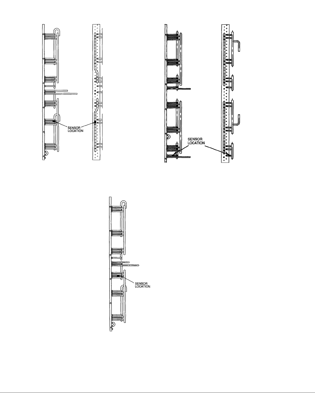
RETURN BEND END
48/50HJ012
RETURN BEND END
48/50TJ012
+
RETURN BEND END
48/50HJJJ014
Fig. 12 - Motormaster® III Sensor Locations — 38AK, AKS and 48/50HJ,TJ UNITS (cont)
Page 9

RETURN BEND END
Fig. 13 — Motormaster® III Sensor Locations — 38AQS Units
yT-
-SENSOR
LOCATION
7^
ir
5s,
!
SENSOR
LOCATION
m
№
RETURN BEND END
50LJQ008
Fig. 14 — Motormaster III Sensor Locations — 50LJQ Units
V
RETURN BEND END
50LJQ012
Page 10

<n> © O
C0.
+® (3) +
CD (D
IF&
cx
<a> © ®
MOTORMASTER III RELAY
EES ®
Fig. 15 — Motormaster® III Relay Location
38AQS008
LEGEND
C — Compressor Contactor
MMSN — Motormaster Sensor
OFC — Outdoor-Fan Contactor
OFM — Outdoor-Fan Motor
NOTES;
1. On 50 Hz units, disconnect yeliow wire connected to Terminai 6
of the outdoor fan contactor (OFC). Tape wire and secure in
side control box
2. See wiring label on unit for more details.
Fig. 17 - Fan Power Wiring - 38AKS009,012 - 208/230 V, 460 V; 60 Hz and 220 V, 400 V; 50 Hz
MOTORMASTER
m
CONTROLLER
MOTORMASTER III RELAY
Fig. 16 - Motormaster ill Relay Location
GRA—•-
VIO •
50LJQ008,012
MMSN
OFM
(
GRN-YEL-
-9
BLK
• YEL
13
23^
BLU
□
C — Compressor Contactor
MMSN — Motormaster Sensor
OFM — Outdoor-Fan Motor
NOTES:
1. On 50 Hz units, disconnect yellow wire connected to Termi
nal 22 of the compressor contactor (C). Tape wire and se
cure inside control box.
2. See wiring label on unit for more details
LEGEND
Fig. 18 - Fan Power Wiring - 38AK008,012; 38AKS008 -208/230 V, 460 V; 60 Hz and 220 V, 400 V; 50 Hz
10
Page 11

LEGEND
MMSN — Motormaster® Sensor
OFC — Outdoor-Fan Contactor
OFM — Outdoor-Fan Motor
TB2 — Terminal Block 2
NOTE: See wiring labei on unit for more detaiis
Fig. 19 - Fan Power Wiring - 38AK008,012; 38AKS008,009,012 - 575 V; 60 Hz
r
MOTORMASTER
JET
CONTROLLER
GRA ■
VIO ■
MMSN
' RED
ORN
BRN
MMSN — Motormaster Sensor
OFC — Outdoor-Fan Contactor
OFM — Outdoor-Fan Motor
NOTE: See wiring label on unit for more detaiis
Fig. 20 - Fan Power Wiring - 50HJ008-012 - 208/230 V; 60 Hz, 50HJ008-014 - 460 V; 60 Hz,
and 50TJ014 - 460 V; 60 Hz
MMSN — Motormaster Sensor
OFM — Outdoor-Fan Motor
NOTE: See wiring label on unit for more details.
Fig. 21 - Fan Power Wiring - 48/50TJ008-012 - 208/230 V and 460 V; 60 Hz
11
Page 12

C2
NOTE. See wiring label on unit for more details.
Fig. 22 - Fan Power Wiring - 50HJ014; 50TJ014 - 208/230 V; 60 Hz
OFM — Outdoor-Fan Motor
NOTE: See wiring label on unit for more details
Fig. 23 - Fan Power Wiring 48HJ008-014; 48TJ014 - 208/230 V and 460 V; 60 Hz
YEL
TB3 — Terminal Block No. 3
NOTE: See wiring label on unit for more details
Fig. 24 — Fan Power Wiring — 48/50HJ,TJ008-014 — 575 V; 60 Hz
12
Page 13

BLK—S
BLK—•
' BLK—S
--------
BLK-
BLU-
MOTORMASTER
Hl
CONTROLLER
LEGEND
Cl — Compressor Contactor No. 1
MMSN — Motormaster® Sensor
OFM — Outdoor-Fan Motor
NOTES:
1. Disconnect black wire on 220-v units and blue wire on 400-v
units connected to capacitor no. 1. Cap with wirenut.
2. See wiring label on unit for more details.
Fig. 25 - Fan Power Wiring — 50TJ008-014 - 220 V and 400 V; 50 Hz
GRA —
VIO ■
MMSN
BRN
RED
ORN
MMR
13
Page 14

CONTROL WIRING
Fig. 27 - Fan Control/Power Wiring - 50LJQ008-012 - 208/230 V and 460 V; 60 Hz
MMR
Fig. 28 — Fan Control/Power Wiring — 50LJQ008-012 — 575 V; 60 Hz
14
Page 15

REAR
UNIT
38
AK008;
AKS008-012;
AQS008
AK012
UNIT
38
AK008;
AKS008-012;
AQS008
AK012 36y2
DIMENSIONS (in.)
LEFT BAFFLE
B C
A
29ys 30V2 35
28%
28% 29% 30V2
REAR BAFFLE
B
A
36V2
37% 38V4
37%
c
38V4 35 2 10 18 26 34 AK012
D E F G H
2
35 2 10 18
D E F G H
35 2
10
10
18
18
, UNIT
' 38
34
26
34 AK012
26
, UNIT
' 38
34
26
AK008;
AKS008-012;
AQS008
AK008;
AKS008-012;
AQS008
LEFT
A B
730
730
A B C
927
927
DIMENSIONS (mm)
LEFT BAFFLE
C D
752 775
752 775
REAR BAFFLE
972
949
972
949
E
889 51 254 457
889 51
E
D
889 51 254 457
51
889
RIGHT
F G H
660
254 457
660
F G H 1
660
457
254
660
1
864
864
864
864
UNIT
38
AK008;
AKS008-012;
A
9'%6
AQS008
AK012 19 7/8 20%
RIGHT BAFFLE RIGHT BAFFLE
B
101%6 11 1 V16 35 2 10 18 26
21%
c
D E F G
35 2
10
18
, UNIT
H
' 38
34 AKS008-012;
26 34 AK012 505
AK008;
AQS008
A
252 275
B C D E F
297
889 51 254 457
527 549
889 51 254
Fig. 29 — Wind Baffie Mounting Detaiis, 38AK,AKS,AQS Units
15
G
457
H 1
660
660
864
864
Page 16

NOTE: Dimensions in ( ) are millimeters
UNIT A
48/50HJ,TJ008,009;
50LJQ008
48/50HJ,TJ012,014;
50LJQ012
43ye
43Vs
SIDE BAFFLE
DIMENSIONS (in.)
B C D E
43^8 44% 35V4 5%
43%
44%
43V4 5%
SIDE OF UNIT
F G
14% 22V4
14%
22V4 30V2 38Vs
H
30V2
J
- -
K
-
UNIT A
48/50HJ,TJ008,009;
50LJQ008
48/50HJ,TJ012,014;
50LJQ012
1096 0
1096.0
UNIT A
48/50HJ008
48/50HJ009; 48/50TJ008;
50LJQ008
48/50TJ009
48/50TJ012
48/50HJ012,014; 48/50TJ014;
50LJQ012
UNIT
48/50HJ008
48/50HJ009; 48/50TJ008;
50LJQ008
48/50TJ009
48/50TJ012
48/50HJ012,014; 48/50TJ014;
50LJQ012
DIMENSIONS (mm)
B C D E
1115.0
1115.0
1134.0
1134.0
1098.0 150.0
FRONT BAFFLE
DIMENSIONS (in)
B C D E
31%
41%
16%
26%
41%
A
805.0
1058.0
423.0
677.0
1058 0
32V2 33V4
42% 43ye 35 1 / 4 11/ 4
17% leys 351/ 4 11/4
27%
42% 43ye
28ya
DIMENSIONS (mm)
B C D
824.0
1077.0
442.0
696.0
1077.0
843 0
1096.0 894.0
461.0
715 0
1096.0
894.0
351/ 4
431/4
431/4
894 0
894.0 32 0
1098.0 32 0
1098.0 32.0
F
150.0 377.0
377 0 566.0
F
11 / 4
11 / 4
11 / 4
91/ 4 171/4 25 1/4 331/4
91/ 4 171/4
91/ 4 171/4
91/ 4 171/4 25 1/4 331/4 41 1/4
91/ 4 171/4 25 1/4 331/4 41 1/4
E F
32.0
32.0
235 2 438.4 641.6 844.8
235 2 438.4
235.2 438.4 641.6 844 8
235.2
235 2 438.4 641 6
G
566 0 774 0
G
G
438 4 641.6
H
774.0 967.6
H
251/4
251/4 33 1 /4
H
641 6
J
-
J
331/ 4
J
844.8
844 8 1048 0
844.8 1048.0
K
K
-
-
-
K
-
-
-
-
-
Fig. 30 — Wind Baffle Mounting Details, 48/50HJ,TJ008-014; 50LJQ008,012
16
Page 17

TROUBLESHOOTING
1. The Motormaster® III control must be securely grounded
to the cabinet of the unit to function properly.
2. The power frequency switch must be in the correct
position for the power supply being used. The control
switch must be set at the thermistor setting.
3. Motormaster III controls may be applied only to spe
cially qualified fan motors. Ensure that the proper fan
motor has been installed with the Motormaster III con
trol. See Tables 2 and 3.
4. A true RMS (Root Mean Square) meter is required to
accurately read the output from the Motormaster III
control because of the electronically controlled output
voltage.
5. Thermistor sensor lead connections should be carefully
rechecked if there is an operational problem. See the
thermistor characteristic for sensor 30GT412176 shown
in Fig. 31. The controller operates between 1600 ohms
and 5800 ohms. At 1600 ohms the controller is at full
voltage. At 5800 ohms the output is at a minimum (10%
of motor speed).
15
LEGEND
¡Tolerance band for allowable Motormaster III resistance values.
20
25 30 35
TEMPERATURE (C)
Fig. 31 - Thermistor Resistance vs Temperature
40
45
50
17
Page 18

Copyright 1995 Carrier Corporation
Manufacturer reserves the right to discontinue, or change at any time, specifications or designs without notice and without incurring obligations.
Bookll II
| 1 | 1
Tab la 1b 3a 5a 2a 5a 6a 6b
|4 |4 |4 |4 PC 111 Catalog No 533-803 Printed in U S.A. Form 38/48/50-4SI Pg 18 1-95 Replaces: New
Page 19

с
19
Page 20

T TEMPLATE
0.130" (3.3mm)
DIA
0.134 (3.4mm)
(6 PLACES TYPICAL)
Page 21

Page 22

DIA (4 PLACES TYPICAL)
-16.05 —
C407.7mm)
MOTORMASTER CONTROLLER TEMPLATE
12.00-
(305.0mm)
20
Page 23

о
1=
о
ш
Page 24

ef^
Copyright 1995 Carrier Corporation
Manufacturer reserves the right to discontinue, or change at any time, specifications or designs without notice and without incurring obiigations.
Book|1 |1 |1 |1 |4 |4 |4 |4 PC 111 Cataiog No. 533-803 Printed in U S A Form 38/48/50-4SI Pg 22 1-95 Repiaces: New
Tab la 1b 3a 5a 2a 5a 6a 6b
 Loading...