

Carrier 38AH044, 38AH054, 38AH064, 38AH074, 38AH084 Installation, Start-up And Service Instructions Manual
...Page 1
Installation, Start-Up and
Service Instructions
CONTENTS
Page
SAFETY CONSIDERATIONS ................ 1
INSTALLATION ............................ 1-37
Step 1 — Rig and Place Unit ............... 1
• DOMESTIC UNITS
• EXPORT UNITS
• PLACING UNITS
Step 2 — Check Compressor Mounting ..... 3
• UNITS 38AH044-084
• UNITS 38AH094-134
Step 3 — Make Refrigerant Piping
Connections .............................. 14
• UNITS 38AH044-084
• UNITS 38AH094-134
Step 4 — Make Electrical Connections ...... 23
• POWER SUPPLY
• FIELD POWER CONNECTIONS
• MAIN POWER
• CONTROL CIRCUIT WIRING
Step 5 — Install Accessories ............... 37
• LOW-AMBIENT OPERATION
• MISCELLANEOUS ACCESSORIES
PRE-START-UP .......................... 37,38
START-UP ................................38-45
SERVICE ..................................46-49
CONTROL ................................49-52
TROUBLESHOOTING ......................53,54
START-UP CHECKLIST ...............CL-1, CL-2
SAFETY CONSIDERATIONS
Installing, starting up, and servicing this equipment can
be hazardous due to system pressures, electrical components, and equipment location (roofs, elevated structures, etc.).
Only trained, qualified installers and service mechanics
should install, start up, and service this equipment.
Untrained personnel can perform basic maintenancefunctions, such as cleaning coils. All other operations should be
performed by trained service personnel.
When working on the equipment, observe precautions in
the literature, and on tags,stickers, and labels attached to the
equipment and any other safety precautions that may apply.
• Follow all safety codes.
• Wear safety glasses and work gloves.
• Use care in handling, rigging, and setting bulky
equipment.
ELECTRIC SHOCK HAZARD.
Open all remote disconnects before servicing
this equipment.
INSTALLATION
Step 1 — Rig and Place Unit —
All units are
designed for overhead rigging, and it is important that this
method be used. Lifting holes are provided in the frame base
rails, which are marked for rigging (see rigging label on the
unit and Tables 1, 2A, and 2B for rigging weights and center
of gravity). It is recommended that field-supplied pipes, of
sufficient length to extend at least 12-in. (305 mm) beyond
the frame, be passed through the holes.
To maintain unit stability while lifting, use 4 cables,
chains, or straps of equal length. Attach one end of
each cable to one pipe end and the other end of each
cable to the overhead rigging point.
Use spreader bars or frame to keep the cables, chains,
and straps clear of the unit sides. Leave standard coil pro-
tection packaging in place during rigging to provide protection to coils. Remove and discard all coil protection after
rigging cables are detached.
DOMESTIC UNITS — For units 38AH044-084, 124, and
134; standard unit packaging consists of coilprotection only.
There is no standard packaging provided for units 38AH094
and 104. Skids are not provided. If overhead rigging is not
available at the jobsite,place the unit on a skid or pad before
dragging or rolling. When rolling, use a minimum of
3 rollers. When dragging, pull the pad or skid. Do not apply
force to the unit. When in final position, raise from above to
lift unit off the pad or skid.
EXPORT UNITS — All export units are mounted on skids
with vertical coil protection. Leave the unit on the skid until
it is in final position. Whileon the skid, the unit can be rolled
or skidded. Apply force to the skid, not to the unit. Use a
minimum of 3 rollers when rolling. When in final position,
raise from above to remove the skid.
PLACING UNITS
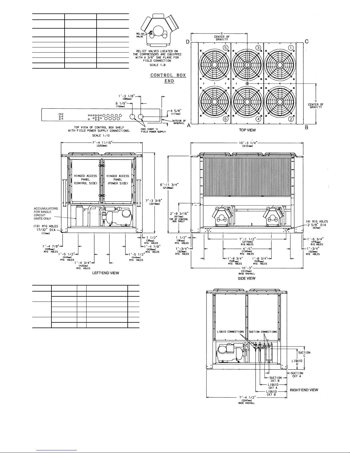
Units 38AH044-084 — RefertoFig.1and 2 for airflow clear-
ances. Recommended minimum clearances are 6 ft (1829 mm)
for unrestricted airflow and service on sides of unit, 5 ft
(1524 mm) on ends, and unrestricted clear air space above
the unit. Provide ample space to connect liquid and suction
lines to indoor unit. For multiple units, allow 8 ft(2440 mm)
separation between units for airflow and service.
Do not forklift these units unless the unit is attached to
a skid designed for forklifting.
38AH044-134
Air-Cooled Condensing Units
50/60 Hz
Manufacturer reserves the right to discontinue, or change at any time, specifications or designs without notice and without incurring obligations.
Book 1
Tab 3a
PC 111 Catalog No. 563-704 Printed in U.S.A. Form 38AH-15SI Pg 1 10-98 Replaces: 38AH-14SI
Page 2
The placement area must be level and strong enough to
support the operating weight of the unit (see Table 3A or
3B). When unit is in proper location, use of mounting holes
in base rails is recommended for securing unit to supporting
structure. For mounting unit on vibration isolators, a perimeter support channel between the unit and the isolators is
recommended. Fasteners for mounting unit are field supplied. Be sure to mount unit level to ensure proper oil return
to compressors.
Units 38AH094-134 — Refer to Fig. 3-6 for airflow
clearances. Recommended minimum clearances are 6 ft
(1829 mm) for unrestricted airflow and service on sides of
unit, 5 ft (1524 mm) on ends, and unrestricted clear air space
above unit. Provide ample space to connect liquid and suction lines to indoor unit. For multiple units, allow
8 ft (2440 mm) separation between units for airflow and
service.
Do not forklift these units unless the unit is attached to
a skid designed for forklifting.
The placement area must be level and strong enough to
support the operating weight of the unit. See Table 4A
or 4B. Refer to the following paragraphs for theproperplacement of the unit.
Units 38AH094,104 — For mounting units on vibration isolators, a perimeter support channel is required between the
unit and the support isolators. The perimeter support channel must be sizedto support the fully assembled unit. Do not
support units on individual isolationsupports. Support channel, hardware, and fasteners are field supplied. When unit is
in proper location, level unit and bolt intoposition with fieldsupplied bolts.
Units 38AH124,134 — For ease of shipment and handling,
unit 38AH124 is shipped as 2 modules (124A and 124B)
and unit 38AH134 is shipped as 2 modules (134Aand 134B).
The modules must be connected at the final installation site
with thefactory-shippedpipingandsheet metal trim kit mounted
on Module 124A or 134A. See Fig. 7.
Do not move assembled 38AH124 or 134 units as a single
assembly. Always move modules individually during installation or at any other time.
Mark installation site for placement of Modules 124A and
124B or Modules 134A and 134B. See Table 4A or 4B for
final assembled dimensions. A service space of 24 in.
(610 mm) is required between the 2 modules for piping and
sheet metal trim installation.
Place Module 124Aor 134Ain position, ensuring that the
control box is at the end opposite the service space. See
Fig. 8.
Remove sheet metal and tubing from Module 124Aor 134A
sheet metal trim kit (Fig. 7). Remove sheet metal cover panels from return-bend end of unit facing the service space.
See Fig. 8. These panels may be discarded or saved for
reinstallation if module is moved from site. See Fig. 9.
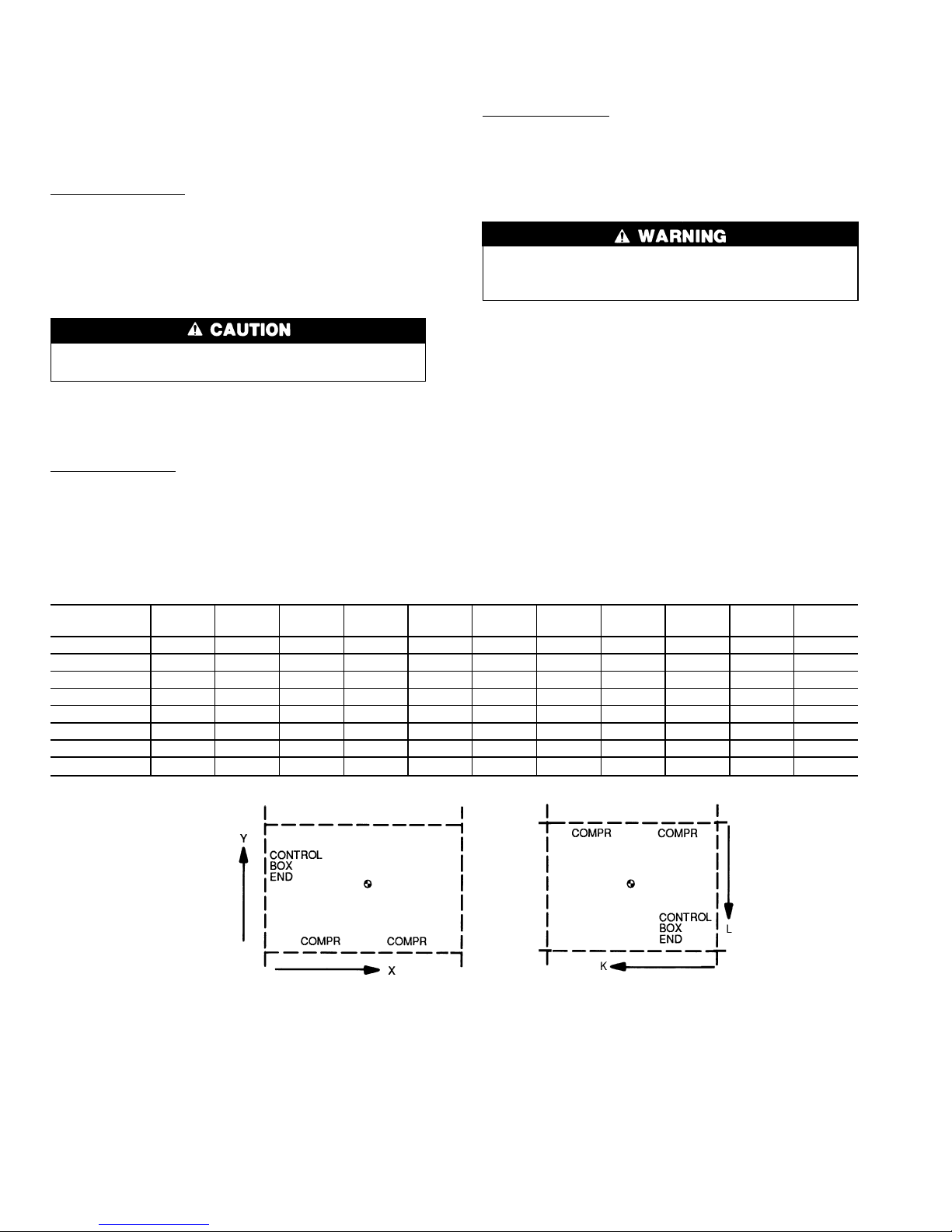
Table 1 — Rigging Center of Gravity — in. (mm)
UNIT
38AH
044 054 064 074 084 094 104
MODULE
124A
MODULE
124B
MODULE
134A
MODULE
134B
Dimension X 49 (1232) 48 (1224) 50 (1260) 57 (1443) 57 (1448) 66 (1676) 63 (1600) 50 (1260) — 50 (1260) —
Dimension Y 39 (984) 39 (978) 38 (968) 39 (993) 39 (991) 31 (787) 34 (851) 38 (968) — 38 (968) —
Dimension X-C 49 (1234) 48 (1229) 50 (1261) 56 (1425) 56 (1422) 66 (1676) 63 (1600) 50 (1260) — 50 (1260) —
Dimension Y-C 39 (993) 39 (991) 39 (986) 40 (1006) 40 (1008) 31 (787) 34 (851) 39 (986) — 39 (986) —
Dimension K ————————50(1260) — 57 (1443)
Dimension L ————————38(968) — 39 (993)
Dimension K-C ————————50(1260) — 56 (1425)
Dimension L-C ————————39(986) — 40 (1006)
LEGEND
——Not Applicable
C—Copper Fin Coils
TOP VIEW, TYPICAL
124, 134 ONLY
2
Page 3
Remove sheet metal cover panels fromreturn-bend end of
Module 124B or 134B. Place Module 124B or 134B in
position. The exposed return-bend ends of each module are
now opposite each other and facing the service space. The
compressors of each module are on opposite sidesofthe unit.
IMPORTANT: Modules must be placed 24 in.
(610 mm) apart and square relative to each other.
The modules are now in position for piping installation and final assembly. See Fig. 8. For mounting units on
vibration isolators, a perimeter support channel is required
between the assembled unit and the support isolators. The
perimeter support channel must be sized to support the fully
assembled unit. Do not support modules on individual isolation supports. Support channel, hardware, and fastenersare
field supplied.
When unit is in proper location, level unit and bolt into
position with field-supplied bolts.
Step 2 — Check Compressor Mounting
UNITS 38AH044-084 — Compressors are mountedon pans
and are held down by 4 bolts during shipment. After unit is
installed, loosen each of these bolts until the snubber washer
can be moved with finger pressure. See Fig. 10.
UNITS 38AH094-134 — Units 38AH094 and104 compressors are mounted on rails and held down by rail bolts during
shipment. After unit is installed, loosen the rail bolts to allow the rails and compressors to float freely on the springs
located under the rails. See Fig. 10.
Units 38AH124 and 134 compressors are mounted on pans
and are held down by 4 bolts during shipment. After unit is
installed, loosen each of these bolts untilsnubber washer can
be moved with finger pressure. See Fig. 10.
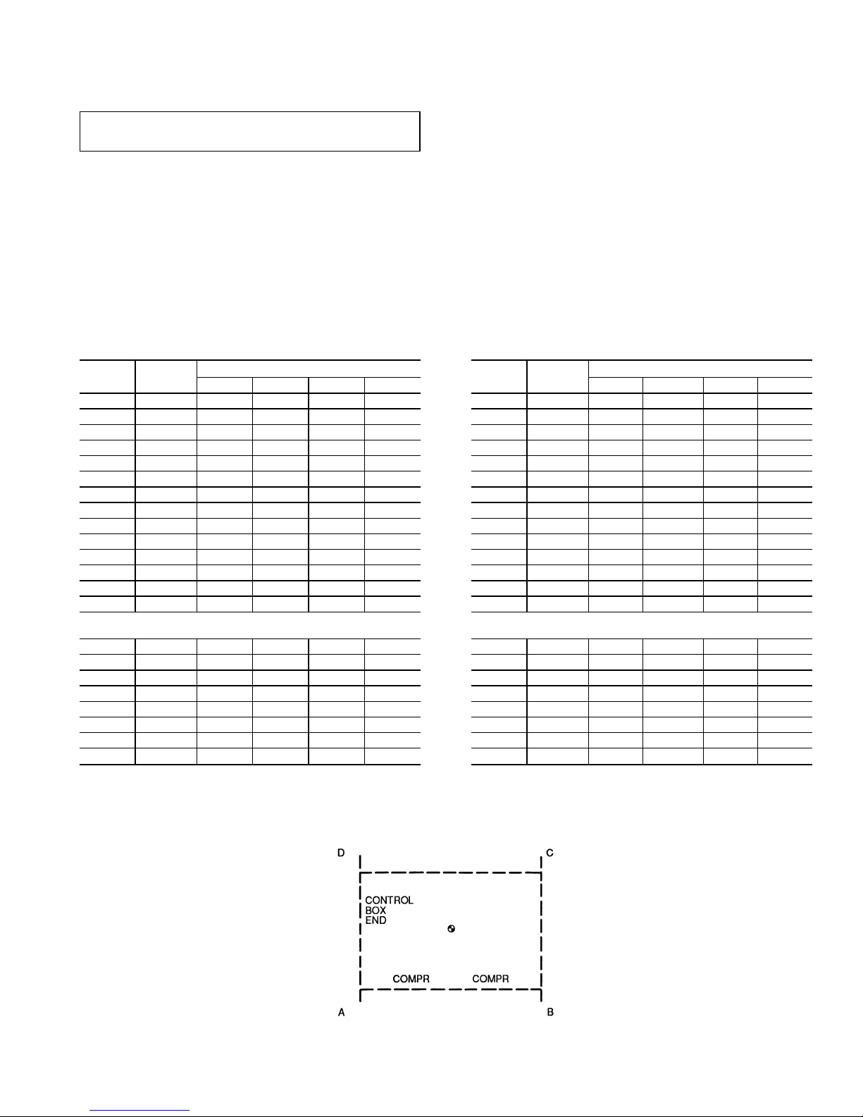
Table 2A — Operational Corner Weights with
Refrigerant Charge (Approximate) — Lb
UNIT
38AH
TOTAL
WEIGHT
OPERATIONAL CORNER WEIGHT
ABCD
044 3259 939 893 695 732
044C 3547 1013 967 765 802
054 3309 964 905 697 742
054C 3597 1034 978 771 814
064 3565 1018 1011 765 771
064C 3998 1125 1117 874 879
074 3812 1146 986 777 903
074C 4229 1272 1059 862 1035
084 4057 1220 1049 827 961
084C 4735 1425 1186 965 1159
094 5088 1114 2192 1182 601
094C 5813 1273 2504 1350 686
104 5435 1240 2138 1302 755
104C 6160 1405 2423 1476 856
MODULE
38AH
124A 3630 1037 1030 779 785
124A-C 4063 1144 1137 889 894
124B 3630 1037 1030 779 785
124B-C 4063 1144 1137 889 894
134A 3630 1037 1030 779 785
134A-C 4063 1144 1137 889 894
134B 3877 1167 997 789 924
134B-C 4294 1293 1080 874 1047
LEGEND
C—Copper Fin Coils
NOTE:Totalweight may differ fromsummationof corner weights due
to rounding of numerals.
Table 2B — Operational Corner Weights with
Refrigerant Charge (Approximate) — Kg
UNIT
38AH
TOTAL
WEIGHT
OPERATIONAL CORNER WEIGHT
ABCD
044 1478 426 405 316 332
044C 1609 460 438 347 364
054 1501 437 411 316 337
054C 1632 469 444 350 369
064 1617 462 459 347 350
064C 1813 510 508 397 399
074 1729 520 447 352 410
074C 1918 577 481 391 470
084 1840 553 476 375 436
084C 2148 646 538 438 526
094 2308 505 994 536 272
094C 2637 577 1136 612 311
104 2465 562 970 591 342
104C 2794 637 1099 670 388
MODULE
38AH
124A 1647 470 467 353 356
124A-C 1843 519 516 403 405
124B 1647 470 467 353 356
124B-C 1843 519 516 403 405
134A 1647 470 467 353 356
134A-C 1843 519 516 403 405
134B 1759 529 452 358 419
134B-C 1948 587 490 396 475
LEGEND
C—Copper Fin Coils
NOTE:Totalweight may differ fromsummationof corner weights due
to rounding of numerals.
TOP VIEW, TYPICAL
3
Page 4
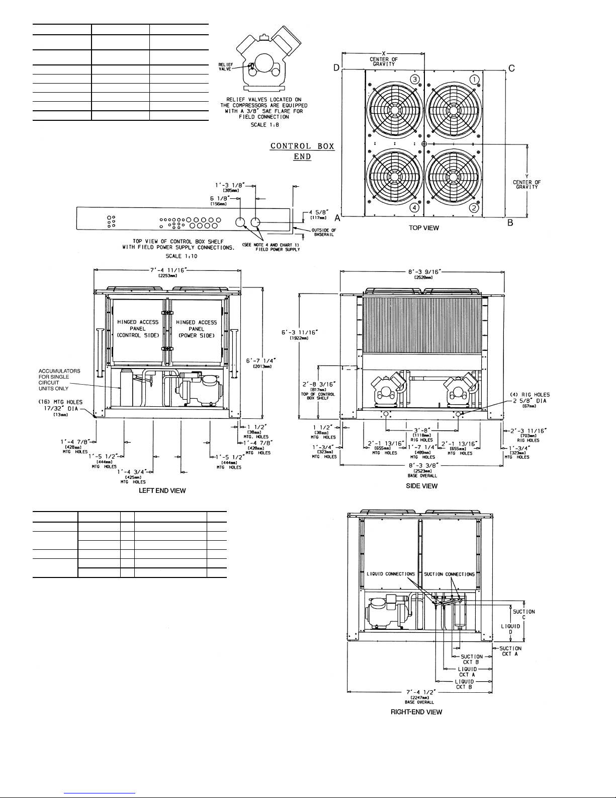
DUAL CKT SINGLE CKT
SUCTION
CONNECTION(S)
21⁄89 Dia [54 mm] 25⁄89 Dia [67 mm]
LIQUID
CONNECTION(S)
7
⁄89 Dia [22 mm] 11⁄89 Dia [29 mm]
SUCTION C 28-
11
⁄169 [627mm] 18-105⁄169 [567mm]
LIQUID D 18-10
1
⁄169 [561mm] 18-105⁄169 [567mm]
SUCTION (Ckt A) 18-7
13
⁄169 [503mm] 28-5⁄89 [626mm]
SUCTION (Ckt B) 28-
5
⁄89 [626mm] —
LIQUID (Ckt A) 28-5
3
⁄49 [756mm] 28-105⁄89 [879mm]
LIQUID (Ckt B) 28-10
5
⁄89 [879mm] —
NOTES:
1. The approximate operating weight of the unit is:
38AH-044--- 3259 lb [1478 kg]
38AH-044--C 3547 lb [1609 kg]
38AH-054--- 3309 lb [1501 kg]
38AH-054--C 3597 lb [1632 kg]
38AH-064--- 3565 lb [1617 kg]
38AH-064--C 3998 lb [1813 kg]
2. Unit must have clearances for airflow as follows:
Top — Do not restrict in any way.
Ends—5ft[1524 mm]
Sides—6ft[1829 mm]
3. Mounting holes may be used to mountunit to concrete pad. They are not recommended for mounting
unit to spring isolators. If spring isolators are used, a perimeter support channel between the unit and
the isolators is recommended.
4. One 3
5
⁄89 (92mm) diameter holeis recommendedfor single-entry poweron size 064(208/230-v) units.
5. See Table1 forrigging center ofgravity (DimensionsX,Y). SeeTable2Aand 2B for A-Dcorner weights.
6. Circled numerals in Top View refer to condenser fans by position.
Chart 1, Field Power Supply Connections
UNIT VOLTAGE Hz DIAMETER — in. [mm] QTY
044 230 50 3
5
⁄8[92] 1
044, 054
208/230 60 3
5
⁄8[92] 1
346, 380/415 50 2
1
⁄2[63] 1
044, 054, 064 460,575,380 60 2
1
⁄2[63] 1
064
208/230 60 2
1
⁄2[63] 2
346, 380/415 50 3
5
⁄8[92] 1
LEGEND
C—Copper Fin Coils
MTG — Mounting
SAE — Society of Automotive Engineers
Fig. 1 — Dimensions — Units 38AH044,054,064
4
Page 5
DUAL CKT SINGLE CKT
SUCTION
CONNECTION(S)
21⁄89 Dia [54 mm] 25⁄89 Dia [67 mm]
LIQUID
CONNECTION(S)
7
⁄89 Dia [22 mm] 11⁄89 Dia [29 mm]
SUCTION C 28-
11
⁄169 [627mm] 18-105⁄169 [567mm]
LIQUID D 18-10
1
⁄169 [561mm] 18-105⁄169 [567mm]
SUCTION (Ckt A) 18-7
13
⁄169 [503mm] 28-5⁄89 [626mm]
SUCTION (Ckt B) 28-
5
⁄89 [626mm] —
LIQUID (Ckt A) 28-5
3
⁄49 [756mm] 28-105⁄89 [879mm]
LIQUID (Ckt B) 28-10
5
⁄89 [879mm] —
Chart 1, Field Power Supply Connections
UNIT VOLTAGE Hz DIAMETER — in. [mm] QTY
074
208/230 60 2
1
⁄2[63] 2
460 60 2
1
⁄2[63] 1
074, 084
346, 380/415 50 3
5
⁄8[92] 1
380 60 3
5
⁄8[92] 1
575 60 2
1
⁄2[63] 1
084
208/230 60 3
5
⁄8[92] 2
460 60 3
5
⁄8[92] 1
LEGEND
C—Copper Fin Coils
MTG — Mounting
SAE — Society of Automotive Engineers
NOTES:
1. The approximate operating weight of the unit is:
38AH-074--- 3812 lb (1729 kg)
38AH-074--C 4229 lb (1918 kg)
38AH-084--- 4057 lb (1840 kg)
38AH-084--C 4735 lb (2148 kg)
2. Unit must have clearances for airflow as follows:
Top — Do not restrict in any way.
Ends—5ft[1524 mm]
Sides—6ft[1829 mm]
3. Mounting holes maybe used to mountunit to concrete pad. They are notrecommended for mounting unit
to spring isolators. If spring isolators are used, a perimeter support channel between the unit and the isolators is recommended.
4. See Table 1 for rigging center of gravity (Dimensions X,Y). See Table 2A and 2B for A-D corner weights.
5. Circled numerals in Top View refer to condenser fans by position.
Fig. 2 — Dimensions — Units 38AH074,084
5
Page 6
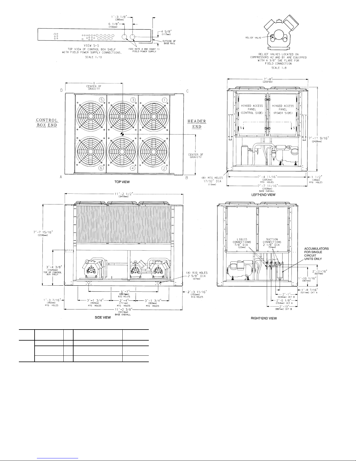
Chart 1, Field Power Supply Connections
UNIT
38AH
VOLTAGE Hz DIAMETER — in. (mm) QUANTITY
094
208/230 60 3
5
⁄8(92) 2
460, 575,
380
60 3
5
⁄8(92) 1
346, 380/415 50 3
5
⁄8(92) 1
LEGEND
C—Copper Fin Coils
MTG — Mounting
SAE — Society of Automotive Engineers
NOTES:
1. The approximate operating weight of the unit is:
38AH-094--- 5088 lb (2308 kg)
38AH-094--C 5813 lb (2637 kg)
2. Unit must have clearances for airflow as follows:
Top — Do not restrict in any way.
Ends—5ft[1524 mm]
Sides—6ft[1829 mm]
3. Mounting holes may be used to mount unit to concrete pad. They are not
recommended for mounting unit to spring isolators.
4. Two 3
5
⁄89 (92-mm) dia holes are recommended for parallel conductors on
208/230 v units.
5. Circled numerals in Top View refer to condenser fans by position.
6. If spring isolators are used, a perimeter support channel between the unit
and the isolators is recommended.
7. See Table 1 for rigging center of gravity (Dimensions X,Y). See Table 2A
and 2B for A-D corner weights.
Fig. 3 — Dimensions — Unit 38AH094
6
Page 7
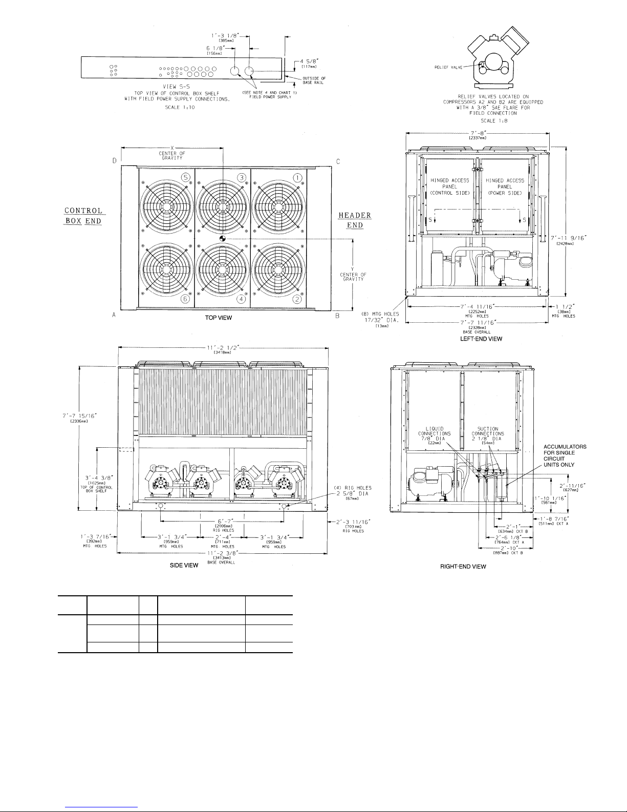
Chart 1, Field Power Supply Connections
UNIT
38AH
VOLTAGE Hz DIAMETER — in. (mm) QUANTITY
104
208/230 60 3
5
⁄8(92) 2
460, 575,
380
60 3
5
⁄8(92) 1
346, 380/415 50 3
5
⁄8(92) 1
Fig. 4 — Dimensions — Unit 38AH104
LEGEND
C—Copper Fin Coils
MTG — Mounting
SAE — Society of Automotive Engineers
NOTES:
1. The approximate operating weight of the unit is:
38AH-104--- 5435 lb (2465 kg)
38AH-104--C 6160 lb (2794 kg)
2. Unit must have clearances for airflow as follows:
Top — Do not restrict in any way.
Ends—5ft[1524 mm]
Sides—6ft[1829 mm]
3. Mounting holes may be used to mount unit to concrete pad. They are not
recommended for mounting unit to spring isolators.
4. Two 3
5
⁄89 (92-mm) dia holes are recommended for parallel conductors on
208/230 v units.
5. Circled numerals in Top View refer to condenser fans by position.
6. If spring isolators are used, a perimeter support channel between the unit
and the isolators is recommended.
7. See Table 1 for rigging center of gravity (Dimensions X,Y). See Table 2A
and 2B for A-D corner weights.
7
Page 8
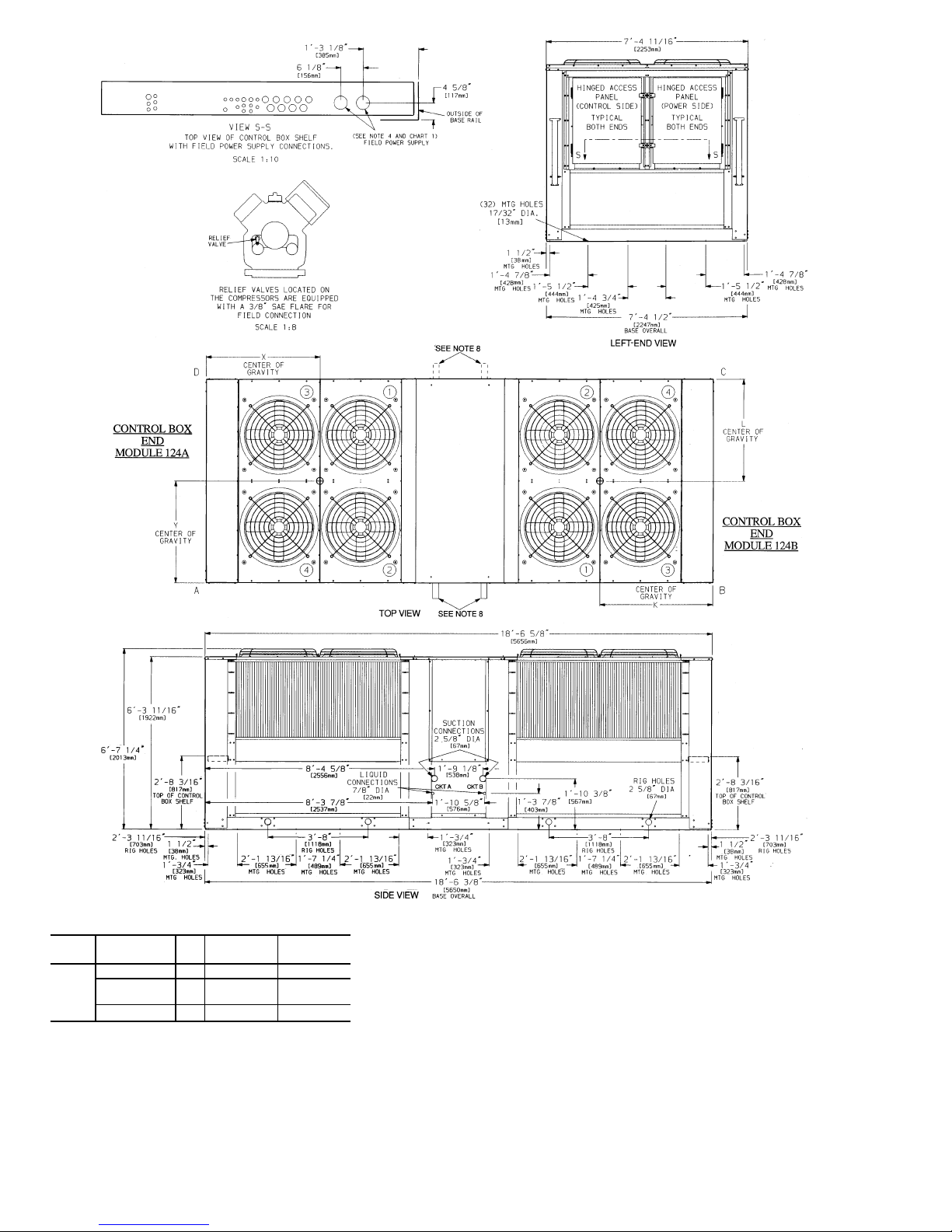
Chart 1, Field Power Supply Connections
UNIT
38AH
VOLTAGE Hz
DIAMETER
(in.)
QUANTITY
124A
124B
208/230 60 3
5
⁄8(92) 1
460, 575,
380
60 2
1
⁄2(63) 1
346, 380/415 50 3
5
⁄8(92) 1
LEGEND
C—Copper Fin Coils
MTG — Mounting
SAE — Society of Automotive Engineers
NOTES:
1. The approximate operating weight of the unit is:
38AH-124--- 7260 lb (3293 kg)
38AH-124--C 8126 lb (3686 kg)
2. Unit must have clearances for airflow as follows:
Top — Do not restrict in any way.
Ends—5ft[1524 mm]
Sides—6ft[1829 mm]
3. Mounting holes may be usedto mount unit to concrete pad. They are notrecommended for mounting unit to spring isolators.
4. One 3
5
⁄89 (92-mm) dia hole is recommended for single-entry power into each
module (124A and 124B) of the 208/230-v units.
5. Circled numerals in Top View refer to condenser fans by position.
6. If spring isolatorsare used, a perimeter support channelbetween the unit and
the isolators is recommended. Do not support each module separately.
7. Each module ofthe unit must beriggedinto position separately.The unit must
not be rigged after modules have been connected.
8. Suction and liquid connections can exit on either side of the unit.
9. Field power supply connections are required for each module.
10. See Table 1 for rigging center of gravity (Dimensions K,L,X,Y). See Table 2A
and 2B for A-D corner weights.
Fig. 5 — Dimensions — Unit 38AH124
8
Page 9
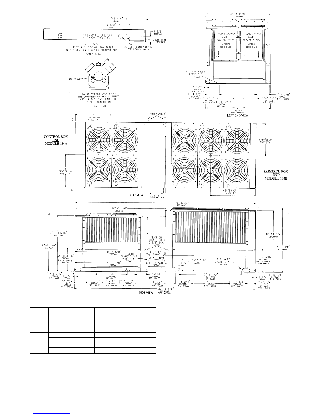
Chart 1, Field Power Supply Connections
UNIT
38AH
VOLTAGE Hz
DIAMETER —
in. (mm)
QUANTITY
134A
208/230 60 3
5
⁄8(92) 1
460, 575, 380 60 2
1
⁄2(63) 1
346, 380/415 50 3
5
⁄8(92) 1
134B
208/230 60 2
1
⁄2(63) 2
460, 575 60 2
1
⁄2(63) 1
380 60 3
5
⁄8(92) 1
346, 380/415 50 3
5
⁄8(92) 1
LEGEND
C—Copper Fin Coils
MTG — Mounting
SAE — Society of Automotive Engineers
NOTES:
1. The approximate operating weight of the unit is:
38AH-134--- 7507 lb (3405 kg)
38AH-134--C 8357 lb (3791 kg)
2. Unit must have clearances for airflow as follows:
Top — Do not restrict in any way.
Ends—5ft[1524 mm]
Sides—6ft[1829 mm]
3. Mounting holes may be used to mount unit to concrete pad. They are not
recommended for mounting unit to spring isolators.
4. One 3
5
⁄89 (92-mm) dia hole is recommended for single-entry power into
Module 134Aand 208/230-vunits.Single entry powerinto Module 134Bis
not recommended.
5. Circled numerals in Top View refer to condenser fans by position.
6. If spring isolators are used, a perimeter support channel between the assembled unitand theisolators isrecommended.Do notsupport eachmodule separately.
7. Each module of the unit must be rigged into position separately. The unit
must not be rigged after modules have been connected.
8. Suction and liquid connections can exit on either side of the unit.
9. Field power supply connections are required for each module.
10. See Table1A or1B for rigging centerof gravity (DimensionsK,L,X,Y). See
Table 2A and 2B for A-D corner weights.
Fig. 6 — Dimensions — Unit 38AH134
9
Page 10
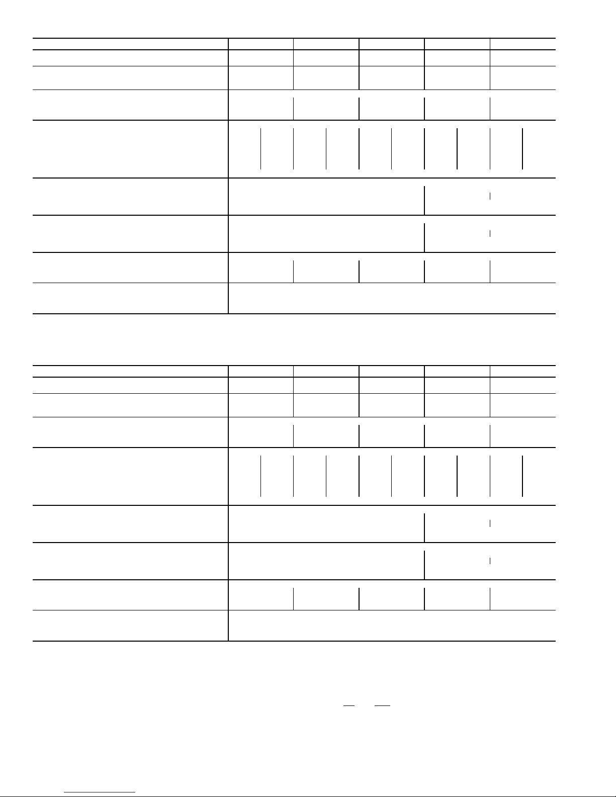
Table 3A — Units 38AH044-084 Physical Data — 50/60 Hz (English)
38AH 044 054 064 074 084
OPERATING WEIGHT WITH Cu-Al 3259 3309 3565 3812 4057
REFRIGERANT (Approx) — Lb Cu-Cu 3547 3597 3998 4229 4735
SHIP WEIGHT WITH COIL PROTECTION ONLY
(Approx) — Lb Cu-Al 3250 3290 3530 3780 4000
Cu-Cu 3538 3578 3963 4197 4678
TYPICAL OPERATING REFRIGERANT R-22
Charge (Approx) — Lb 62 72 88 104 130
Qty of Circuits Std 22222
Opt 11111
COMPRESSOR Type...Rpm Reciprocating Semi-Hermetic...1750 @ 60 Hz; 1458 @ 50 Hz
(Qty Cylinder) Compressor* Std (4) A1 (4) B1 (4) A1 (6) B1 (6) A1 (6) B1 (6) A1 (6) B1 (6) A1 (6) B1
Model No. 06E Std 250 250 250 265 265 275 275 299 299 299
(Qty Cylinder) Compressor* Opt (4) A1 (4) A2 (6) A1 (4) A2 (6) A1 (6) A2 (6) A1 (6) A2 (6) A1 (6) A2
Model No. 06E Opt 250 250 265 250 275 265 299 275 299 299
Oil Charge (Pt) Std 17 17 17 21 21 21 21 19 19 19
Opt 17 17 21 17 21 21 19 21 19 19
Capacity Control Steps† 4
CONDENSER FANS (6 Blade) — 60 Hz
Qty...Dia (in.) 4...30 6...30
Airflow (Cfm) 35,000 52,000 51,000
Speed (Rpm) 1140 1140
Total Power (kW) 6.2 9.3
CONDENSER FANS (6 Blade) — 50 Hz
Qty...Dia (in.) 4...30 6...30
Airflow (Cfm) 35,000 52,000 51,000
Speed (Rpm) 950 950
Total Power (kW) 6.2 9.3
CONDENSER COIL Enhanced Copper Tubes, Aluminum Lanced Fin
Rows...Fins per in. 2...17 2...17 3...17 2...19 3...17
Face Area (sq ft) 80.5 80.5 80.5 116.7 116.7
Storage Capacity (Lb per Circuit) at 120 F 35 35 55 55 80
CONNECTIONS
Suction, ODF (in.)** 2
1
⁄
8
Liquid, ODF (in.)**
7
⁄
8
Hot Gas Bypass, ODF (in.)
5
⁄
8
Table 3B — Units 38AH044-084 Physical Data — 50/60 Hz (SI)
38AH 044 054 064 074 084
OPERATING WEIGHT WITH Cu-Al 1478 1501 1617 1729 1840
REFRIGERANT (Approx) — Kg Cu-Cu 1609 1632 1813 1918 2148
SHIP WEIGHT WITH COIL PROTECTION ONLY
(Approx) — Kg Cu-Al 1474 1492 1601 1715 1814
Cu-Cu 1605 1623 1798 1904 2122
TYPICAL OPERATING REFRIGERANT R-22
CHARGE (Approx) — Kg 28.1 32.7 39.9 47.2 58.9
Qty of Circuits Std 22222
Opt 11111
COMPRESSOR Type...R/s Reciprocating Semi-Hermetic...29.2 @ 60 Hz; 24.3 @ 50 Hz
(Qty Cylinder) Compressor* Std (4) A1 (4) B1 (4) A1 (6) B1 (6) A1 (6) B1 (6) A1 (6) B1 (6) A1 (6) B1
Model No. 06E Std 250 250 250 265 265 275 275 299 299 299
(Qty) Cylinder) Compressor* Opt (4) A1 (4) A2 (6) A1 (4) A2 (6) A1 (6) A2 (6) A1 (6) A2 (6) A1 (6) A2
Model No. 06E Opt 250 250 265 250 275 265 299 275 299 299
Oil Charge (L) Std 8.0 8.0 8.0 9.9 9.9 9.9 9.9 9.0 9.0 9.0
Opt 8.0 8.0 9.9 8.0 9.9 9.9 9.0 9.9 9.0 9.0
Capacity Control Steps† 4
CONDENSER FANS (6 Blade) — 50 Hz
Qty...Dia (mm) 4...762 6...762
Airflow (L/s) 16,500 24,500 24,100
Speed (R/s) 15.8 15.8
Total Power (kW) 6.2 9.3
CONDENSER FANS (6 Blade) — 60 Hz
Qty...Dia (mm) 4...762 6...762
Airflow (L/s) 16,500 24,500 24,100
Speed (R/s) 19.0 19.0
Total Power (kW) 6.2 9.3
CONDENSER COIL Enhanced Copper Tubes, Aluminum Lanced Fin
Rows...Fins per m 2...669 2...669 3...669 2...782 3...669
Face Area (sq m) 7.48 7.48 7.48 10.84 10.84
Storage Capacity (Kg per Circuit) at 48.9 C 16 16 25 25 36
CONNECTIONS
Suction, ODF (in.)** 2
1
⁄
8
Liquid, ODF (in.)**
7
⁄
8
Hot Gas Bypass, ODF (in.)
5
⁄
8
LEGEND
Cu-Al — Copper tubes with aluminum fins
Cu-Cu — Copper tubes with copper fins
ODF — Outside Diameter, Female
Opt — Optional Single-Circuit Units
Std — Standard Dual-Circuit Units
*Compressor A1 is lead on standard and optional single-circuit units.
†Capacity control steps listed are for constant-volume units with no accesso-
ries. Refer to Table 19A or 19B, page 48, for additional system capacity
information.
**For single-circuit units, suction ODF is 2
5
⁄8in. (66.7 mm) and liquid ODF is
11⁄8in. (28.6 mm). Single circuits have a factory-installed manifold; no
field modification is required.
NOTES:
1. Certified dimensional drawings available on request.
2. Equivalent connection values in mm are as follows:
in. mm
5
⁄
8
15.9
7
⁄
8
22.2
2
1
⁄
8
54.0
10
Page 11
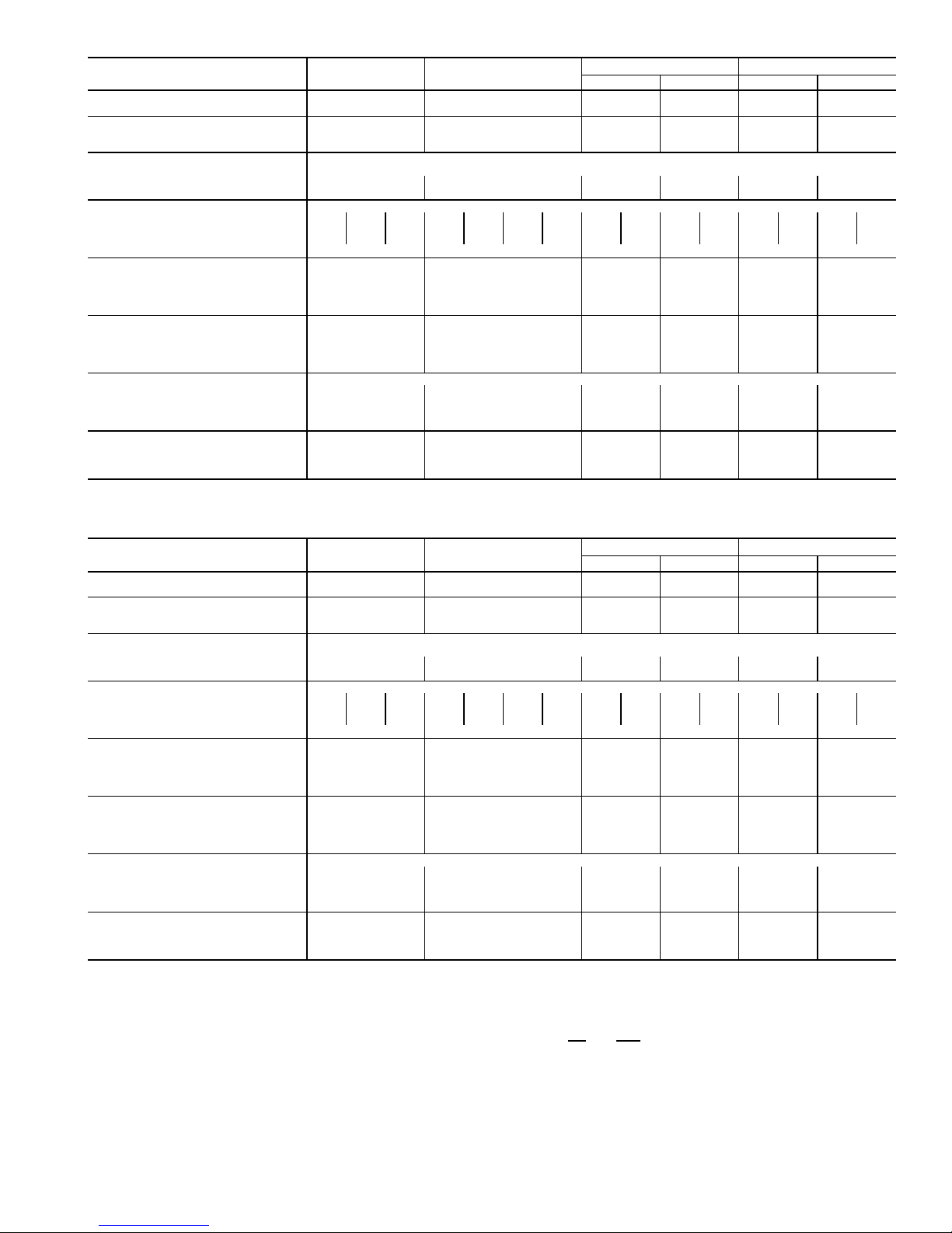
Table 4A — Units 38AH094-134 Physical Data — 50/60 Hz (English)
38AH 094 104
124 134
124A 124B 134A 134B
OPERATING WEIGHT WITH Cu-Al 5088 5435 3630* 3630* 3630* 3877*
REFRIGERANT (Approx) — Lb Cu-Cu 5813 6160 4063* 4063* 4063* 4294*
SHIP WEIGHT WITH Cu-Al 5630 5990 3907* 3907* 3907* 4080*
COIL PROTECTION AND SKID Cu-Cu 6355 6715 4340* 4340* 4340* 4497*
(Approx) — Lb
TYPICAL OPERATING
REFRIGERANT CHARGE
R-22
(Approx) — Lb 148 135 88 88 88 104
Qty of Circuits 2 2 1111
COMPRESSOR Type...Rpm Reciprocating Semi-Hermetic...1750 @ 60 Hz; 1460 @ 50 Hz
(Qty Cylinder) Compressor† (6)A1 (4)A2 (6)B1 (6)A1 (4)A2 (6)B1 (6)B2 (6)A1 (6)A2 (6)A1 (6)A2 (6)A1 (6)A2 (6)A1 (6)A2
Model No. 06E −275 −250 −299 −265 −250 −265 −265 −275 −265 −275 −265 −275 −265 −299 −275
Oil Charge (Pt) 21 17 19 21 17 21 21 21 21 21 21 21 21 19 21
Capacity Control Steps** 5 6 3333
CONDENSER FANS (6 Blade) — 60 Hz
Qty...Dia (in.) 6...30 6...30 4...30 4...30 4...30 6...30
Airflow (Cfm) 52,000 52,000 35,000 35,000 35,000 52,000
Speed (Rpm) 1140 1140 1140 1140 1140 1140
Total Power (kW) 9.4 9.5 6.4 6.4 6.4 9.2
CONDENSER FANS (6 Blade) — 50 Hz
Qty...Dia (in.) 6...30 6...30 4...30 4...30 4...30 6...30
Airflow (Cfm) 52,000 52,000 35,000 35,000 35,000 52,000
Speed (Rpm) 950 950 950 950 950 950
Total Power (kW) 9.4 9.5 6.4 6.4 6.4 9.2
CONDENSER COIL Enhanced Copper Tubes, Aluminum Lanced Fin
Rows...Fins per in. 3...17 3...17 3...17 3...17 3...17 2...19
Face Area (sq ft) 128.3 128.3 80.5 80.5 80.5 116.7
Storage Capacity
(Lb per circuit) at 120 F
178 178 110 110 110 110
CONNECTIONS
Suction, ODF (in.) 2
1
⁄
8
21⁄
8
25⁄
8
25⁄
8
25⁄
8
25⁄
8
Liquid, ODF (in.)
7
⁄
8
7
⁄
8
11⁄
8
11⁄
8
11⁄
8
11⁄
8
Hot Gas Bypass, ODF (in.)
5
⁄
8
5
⁄
8
5
⁄
8
5
⁄
8
5
⁄
8
5
⁄
8
Table 4B — Units 38AH094-134 Physical Data — 50/60 Hz (SI)
38AH 094 104
124 134
124A 124B 134A 134B
OPERATING WEIGHT WITH Cu-Al 2308 2465 1647* 1647* 1647* 1759*
REFRIGERANT (Approx) — Kg Cu-Cu 2637 2794 1843* 1843* 1843* 1948*
SHIP WEIGHT WITH Cu-Al 2554 2717 1860* 1860* 1860* 1851*
COIL PROTECTION AND SKID Cu-Cu 2883 3046 1968* 1968* 1968* 1968*
(Approx) — Kg
TYPICAL OPERATING
REFRIGERANT CHARGE
R-22
(Approx) — Kg 67.1 61.2 39.9 39.9 39.9 47.2
Qty of Circuits 2 2 1111
COMPRESSOR Type...R/s Reciprocating Semi-Hermetic...29.2 @ 60 Hz; 24.3 @ 50 Hz
(Qty Cyliner) Compressor† (6)A1 (4)A2 (6)B1 (6)A1 (4)A2 (6)B1 (6)B2 (6)A1 (6)A2 (6)A1 (6)A2 (6)A1 (6)A2 (6)A1 (6)A2
Model No. 06E −275 −250 −299 −265 −250 −265 −265 −275 −265 −275 −265 −275 −265 −299 −275
Oil Charge (L) 10 8 9 10 8 1010101010101010 9 10
Capacity Control Steps** 5 6 3333
CONDENSER FANS (6 Blade) — 60 Hz
Qty...Dia (mm) 6...762 6...762 4...762 4...762 4...762 6...762
Airflow (L/s) 24,544 24,544 16,520 16,520 16,520 24,544
Speed (R/s) 19 19 19 19 19 19
Total Power (kW) 9.4 9.5 6.4 6.4 6.4 9.2
CONDENSER FANS (6 Blade) — 50 Hz
Qty...Dia (mm) 6...762 6...762 4...762 4...762 4...762 6...762
Airflow (L/s) 24,544 24,544 16,520 16,520 16,520 24,544
Speed (R/s) 15.8 15.8 15.8 15.8 15.8 15.8
Total Power (kW) 9.4 9.5 6.4 6.4 6.4 9.2
CONDENSER COIL Enhanced Copper Tubes, Aluminum Lanced Fin
Rows...Fins per m 3...669.3 3...669.3 3...669.3 3...669.3 3...669.3 2...781.6
Face Area (sq m) 11.9 11.9 7.5 7.5 7.5 10.8
Storage Capacity
(Kg per circuit) at 49 C
81 81 50 50 50 50
CONNECTIONS
Suction, ODF (in.) 2
1
⁄
8
21⁄
8
25⁄
8
25⁄
8
25⁄
8
25⁄
8
Liquid, ODF (in.)
7
⁄
8
7
⁄
8
11⁄
8
11⁄
8
11⁄
8
11⁄
8
Hot Gas Bypass, ODF (in.)
5
⁄
8
5
⁄
8
5
⁄
8
5
⁄
8
5
⁄
8
5
⁄
8
LEGEND
Cu-Al — Copper Tubes with Aluminum Fins
Cu-Cu — Copper Tubes with Copper Fins
ODF — Outside Diameter, Female
*Includes piping and trim kit.
†Compressors are shipped with minimum oil charge.
**Capacity control steps listed are for constant volume units with no accesso-
ries. Refer to Table 20, page 48, for additional system capacity information.
NOTES:
1. Unit 38AH124 consists of one 124A module and one 124B module. Unit
38AH134 consists of one 134A module and one 134B module.
2. Certified dimensional drawings available on request.
3. Equivalent connection values in mm are as follows:
in. mm
5
⁄
8
15.9
7
⁄
8
22.2
11⁄
8
28.6
2
1
⁄
8
54.0
25⁄
8
66.7
11
Page 12
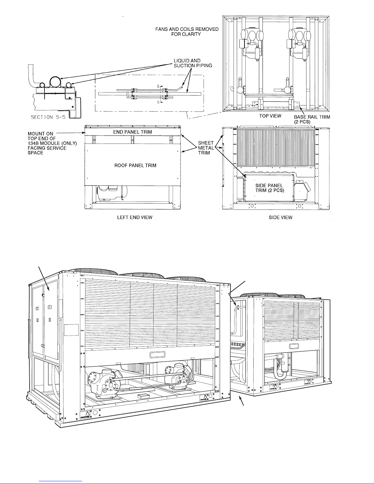
Fig. 7 — Modules 38AH124A or 134A — Shipping Locations of Piping
and Sheet Metal Trim Kit
RIG
HERE
RIG
HERE
RIG
HERE
RIG
HERE
CONTROL
BOX
SHEET METAL COVER
PANEL (REMOVED)
24-in. (610-mm)
SERVICE SPACE
Fig. 8 — Correct Placement of Modules Without Piping
and Sheet Metal Trim (Unit 38AH134 Shown)
12
Page 13
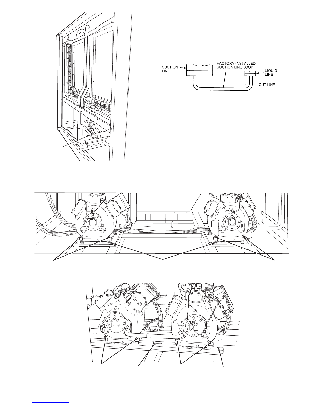
FACTORYINSTALLED
SUCTION
LINE LOOP
Fig. 9A — Typical Module with Cover
Panels Removed
Fig. 9B — Field-Installed Suction Line Loop
38AH044-084,124,134
MOUNTING SPRINGS
SHIPMENT BOLTS
SHIPMENT BOLTS
38AH094,104
MOUNTING
BOLTS RAIL BOLT (3) (2 SHOWN)
RAIL BOLT (3) (2 SHOWN)
MOUNTING
BOLTS
Fig. 10 — Outer View, Compressor Mounting
13
Page 14
Step 3 — Make Refrigerant Piping
Connections
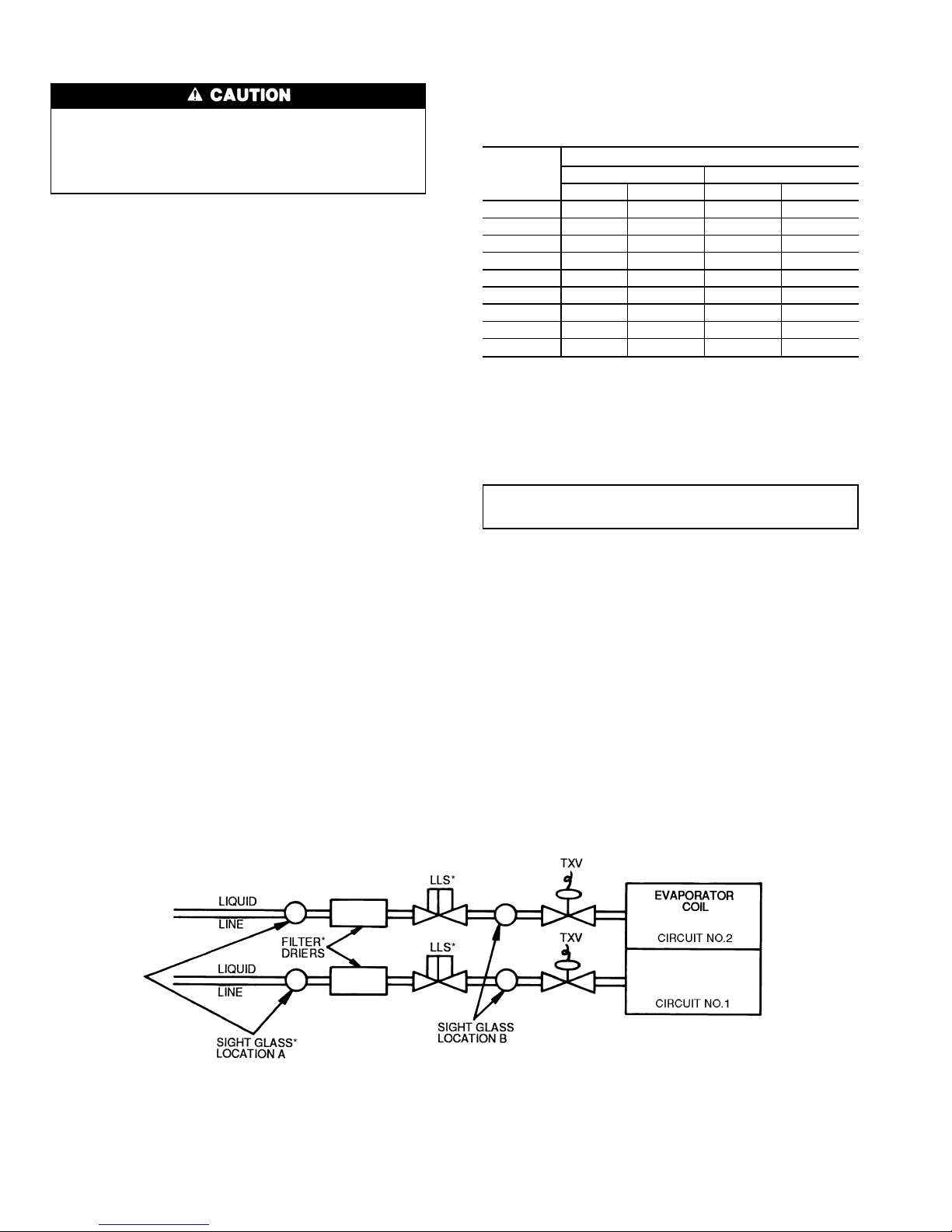
The field-supplied liquid line solenoid valve must be
installed at the evaporator to avoid possible compressor
damage during unit operation. See Fig. 11 (for 38AH044084 dual-circuit and 38AH094-134 units), or Fig. 12 (for
38AH044-084 optional single-circuit units).
The units have largesuctionlinestominimizefrictionlosses.
The units also have the ability to operate at low capacity.
Because of these capabilities, use special care with suction
piping and suction risers to ensure proper compressor oil
return under all operating conditions. Maximum allowable
vertical separation between the condensing unit and the evaporator is shown in Table 5. Size suction lines in accordance
with Tables 6A or 6B through 9A or 9B and Fig. 13. Mount
liquid line solenoid valve just ahead of the TXVs (thermostatic expansion valves) which will be mounted at the
evaporator. See Fig. 11 (for 38AH044-084 dual-circuit and
38AH094-134 units) or Fig. 12 (for 38AH044-084 optional
single-circuit units).
T oachievegood mixing of the refrigerant leaving the evaporator suction header for proper sensing by the TXV bulb:
1. Install a minimum of two 90-degree elbows upstream of
the TXV bulb location. See Fig. 14 (for 38AH044-084
dual-circuit and 38AH094-134 units) or Fig. 15 (for
38AH044-084 optional single-circuit units).
2. Locate the TXV bulb on a vertical riser, where possible.
If a horizontal location is necessary, secure the bulb at
approximately the 4 o’clock position.
3. Size the suction line from the evaporator to the common
suction line to achieve high refrigerant velocity. See
Tables 6A or 6B through 9A or 9B and Fig. 13.
If an oil return connection at the bottom of the suction
header is supplied with an evaporator, tee-in this connection
ahead of first mixing elbow. See Fig. 14 (for 38AH044-084
dual-circuit and 38AH094-134 units) or Fig. 15(for38AH044084 optional single-circuit units). When the compressor is
below the evaporator, the riser at the evaporator should extend to the top of the evaporator section. After the riser is
installed, the suction line can elbow down immediately.
Install a field-supplied filter drier and sight glasses in each
refrigerant system. Select the filter drier for maximum unit
capacity and minimum pressuredrop.Figure1 1(for 38AH044084 dual-circuit and 38AH094-134 units) or Fig. 12 (for
38AH044-084 optional single-circuit units) shows required
location of solenoid valves and recommended locations for
the filter driers and sight glasses. Complete the refrigerant
piping from the evaporator to the condenser before opening
the liquid and suction lines at the condenser.
Table 5 — Liquid Lift
UNIT
38AH
MAXIMUM LIQUID LIFT
60 Hz 50 Hz
FtMFtM
044 69 21.0 57.5 17.5
054 75 23.0 75.0 23.0
064 75 23.0 65.0 19.8
074 45 13.7 37.5 11.4
084 75 23.0 75.0 23.0
094 55 16.7 46.0 14.0
104 50 15.2 42.0 12.8
124 75 23.0 65.0 19.8
134 45 13.7 37.5 11.4
UNITS 38AH044-084 — Relieve the pressurecaused by the
holding charge into a refrigerant recovery system. Uncap
the suction line and cut the run-around tube at the liquid line
as close to the loop elbow as possible. This will leave
approximately 2 in. (50 mm) of straight tube for liquid line
connection.
IMPORTANT: Protect the liquid valves from the heat
of brazing.
Leak test the entire system by using soap bubbles and
nitrogen or R-22 with an electronic leak detector.
Purge nitrogen or reclaim R-22 from system after completion of leak-checking procedure. Repair leak if one is
found. When finished, evacuate and dehydrate system using
the methods described in CarrierGTAC II (General Training
Air Conditioning II), Module 4, System Dehydration.
UNITS 38AH094-134 — Relieve the R-22 holding charge
of each circuit into a refrigerant recovery system. Remove
the liquid line to factory-installed suction line loop by cutting the loop at the liquid valve. (See Fig. 9A and 9B.) Cut
as close to the 90-degree bend in the loop as possible. The
remaining tube piece in the valve will be used for brazing
the liquid line. Unbraze and remove the cap from the liquid
line. For 38AH094 and 104 units, sweat-connect the liquid
and suction lines from the evaporator. For 38AH124 and 134
units, see Piping Kit Connections on page 21.
LEGEND
LLS — Liquid Line Solenoid
TXV — Thermostatic Expansion Valve
*Field-Supplied.
Fig. 11 — Required Location of Solenoid Valves and Recommended Filter Drier and
Sight Glass Locations for 38AH044-084 Dual-Circuit and 38AH094-134 Units
14
Page 15
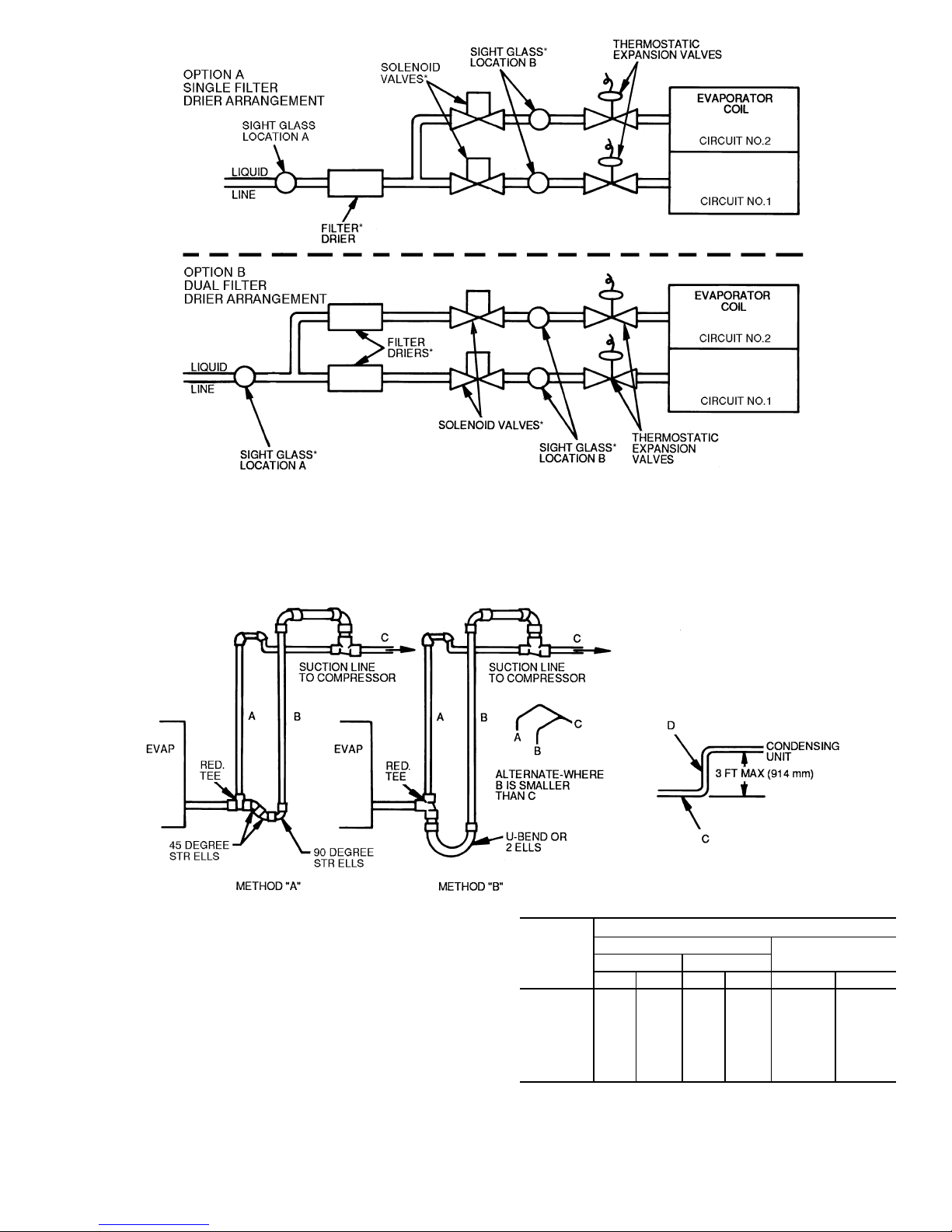
*Field-Supplied.
Fig. 12 — Required Location of Solenoid Valves and Recommended Filter Drier and
Sight Glass Locations for 38AH044-084 Optional Single-Circuit Units
LEGEND
A—Pipe A, Suction Riser, without Trap
B—Pipe B, Suction Riser with Trap
C—Suction Line to Condensing Unit
D—Pipe D, Suction Riser Short Lift
RED. — Reducer
STR — Street
NOTES:
1. Short riser, pipe D, is used when routing suction line to condensing unit connection. See table at right.
2. See Tables 6A-9B for values of A, B, and C.
UNIT
38AH
PIPE D DIAMETER
Dual Circuit*
Single Circuit*
AB
in. mm in. mm in. mm
044 1
5
⁄841 15⁄
8
41 21⁄
8
54
054 15⁄841 15⁄
8
41 21⁄
8
54
064 1
5
⁄841 21⁄
8
54 21⁄
8
54
074 21⁄854 21⁄
8
54 21⁄
8
54
084 21⁄854 21⁄
8
54 25⁄8† 67†
094, 104 2
1
⁄854 21⁄
8
54 — —
124, 134 25⁄867 25⁄
8
67 — —
*Maximum length of riser is 3 ft (914 mm).
†Double suction riser required if accessory unloader is field
installed.
Fig. 13 — Double Suction Riser Construction
15
Page 16
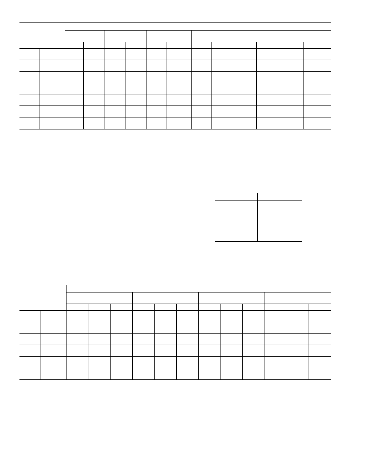
Table 6A — Refrigerant Piping Requirements — 38AH044-104 Dual-Circuit Units — 60 Hz
UNIT
38AH
TOTAL LINEAR LENGTH OF INTERCONNECTING PIPE — FT (M)
15-25
(4.6-7.6)
25-50
(7.6-15.2)
50-75
(15.2-22.9)
75-100
(22.9-30.5)
100-150
(30.5-45.7)
150-200
(45.7-61.0)
LSLSL S L S L S L S
044
Ckt A
5
⁄
8
15⁄
8
7
⁄
8
15⁄
8
7
⁄
8
21⁄
8
7
⁄
8
21⁄
8
7
⁄
8
21⁄
8
7
⁄
8
21⁄
8
Ckt B
5
⁄
8
15⁄
8
7
⁄
8
15⁄
8
7
⁄
8
21⁄
8
7
⁄
8
21⁄
8
7
⁄
8
21⁄
8
7
⁄
8
21⁄
8
054
Ckt A
5
⁄
8
15⁄
8
7
⁄
8
15⁄
8
7
⁄
8
21⁄
8
7
⁄
8
21⁄
8
7
⁄
8
21⁄
8
7
⁄
8
21⁄
8
Ckt B
7
⁄
8
15⁄
8
7
⁄
8
21⁄
8
7
⁄
8
21⁄
8
11⁄
8
21⁄
8
11⁄
8
21⁄
8
11⁄
8
25⁄8*
064
Ckt A
7
⁄
8
15⁄
8
7
⁄
8
21⁄
8
7
⁄
8
21⁄
8
7
⁄
8
21⁄
8
11⁄
8
21⁄
8
11⁄
8
25⁄8†
Ckt B
7
⁄
8
21⁄
8
7
⁄
8
21⁄
8
7
⁄
8
21⁄
8
11⁄
8
21⁄
8
11⁄
8
25⁄
8
11⁄
8
25⁄
8
074
Ckt A
7
⁄
8
21⁄
8
7
⁄
8
21⁄
8
7
⁄
8
21⁄
8
11⁄
8
21⁄
8
11⁄
8
25⁄8†11⁄825⁄8†
Ckt B
7
⁄
8
21⁄
8
11⁄
8
21⁄
8
11⁄
8
21⁄
8
11⁄
8
25⁄
8
13⁄
8
25⁄
8
13⁄
8
25⁄
8
084
Ckt A
7
⁄
8
21⁄
8
11⁄
8
21⁄
8
11⁄
8
21⁄
8
11⁄
8
25⁄8†13⁄825⁄8†13⁄825⁄8†
Ckt B
7
⁄
8
21⁄
8
11⁄
8
21⁄
8
11⁄
8
21⁄
8
11⁄
8
25⁄
8
13⁄
8
25⁄
8
13⁄
8
25⁄
8
094
Ckt A
7
⁄
8
21⁄
8
11⁄
8
21⁄
8
11⁄
8
25⁄8†11⁄825⁄8†13⁄825⁄8†13⁄831⁄8**
Ckt B
7
⁄
8
21⁄
8
7
⁄
8
21⁄
8
11⁄
8
21⁄
8
11⁄
8
25⁄
8
11⁄
8
25⁄
8
13⁄
8
25⁄
8
104
Ckt A
7
⁄
8
21⁄
8
11⁄
8
21⁄
8
11⁄
8
25⁄8†11⁄825⁄8†13⁄825⁄8†13⁄831⁄8**
Ckt B
7
⁄
8
21⁄
8
11⁄
8
21⁄
8
11⁄
8
25⁄
8
11⁄
8
25⁄
8
13⁄
8
31⁄8** 13⁄
8
31⁄8**
LEGEND
L—Liquid Line
S—Suction Line
*Double suction riser required on units with field installed unloader
on circuit B compressor if condensing unit is elevated above
evaporator.
†Double suction riser required on units with field installed unloader
on circuit B compressor if condensing unit is elevated above
evaporator.
**Double suction riser required on all unit configurations if condens-
ing unit is elevated above evaporator.
NOTES:
1. Addition of 2 unloaders to circuit B compressor is not
recommended.
2. 38AH094 and 38AH104 piping sizes apply only to factory supplied unit configurations. They do NOT take into account any field
installed unloaders.
3. Piping sizes are based on unit operation above 40F(4.4C)saturated suction temperature (SST). When operating below 40 F
(4.4 C),referto Carrier System Design Manual,E20-IIT pipingdesign program, or ASHRAE Handbook to select proper line sizes.
4. Pipe sizes are based on the total linear length shown for each
column, plus a 50% allowance for fittings.
5. Suction and liquid linesizingis based onpressuredrop equivalent
to 2 F (1.1 C) at nominal rating conditions. Higher pressure drop
design criteria may allow selection of smaller pipe sizes, but at a
penalty of decreased system capacity and efficiency.
6. Double suction risers may be required if condensing unit is
elevated above the evaporator.Seefootnotesand double suction
riser table below.
7. Refer to Carrier System Design Manual or to E20-II design
programs for further information on selecting pipe sizes for split
systems.
8. All pipe sizes are OD inches. Equivalent sizes in millimeters
follow:
in. mm
5
⁄
8
15.9
7
⁄
8
22.2
11⁄
8
28.6
1
3
⁄
8
34.9
15⁄
8
41.3
2
1
⁄
8
54.0
25⁄
8
66.7
31⁄
8
79.4
Table 6B — Refrigerant Piping Requirements for Double Suction Risers,
38AH054-104 Dual-Circuit Units — 60 Hz
UNIT
38AH
TOTAL LINEAR LENGTH OF INTERCONNECTING PIPE — FT (M)
50-75
(15.2-22.9)
75-100
(22.9-30.5)
100-150
(30.5-45.7)
150-200
(45.7-61.0)
ABCABCABCABC
054
Ckt A ————————————
Ckt B —————————1
5
⁄82
1
⁄82
5
⁄
8
064
Ckt A —————————1
5
⁄82
1
⁄82
5
⁄
8
Ckt B ————————————
074
Ckt A ——————1
5
⁄82
1
⁄82
5
⁄81
5
⁄82
1
⁄82
5
⁄
8
Ckt B ————————————
084
Ckt A ———1
5
⁄82
1
⁄82
5
⁄81
5
⁄82
1
⁄82
5
⁄81
5
⁄82
1
⁄82
5
⁄
8
Ckt B ————————————
094
Ckt A 1
5
⁄
8
21⁄
8
25⁄
8
15⁄
8
21⁄
8
25⁄
8
15⁄
8
21⁄
8
25⁄
8
15⁄
8
25⁄
8
31⁄
8
Ckt B ————————————
104
Ckt A 1
3
⁄
8
21⁄
8
25⁄
8
13⁄
8
21⁄
8
25⁄
8
13⁄
8
21⁄
8
25⁄
8
15⁄
8
25⁄
8
31⁄
8
Ckt B ——————1
3
⁄82
5
⁄83
1
⁄81
5
⁄82
5
⁄83
1
⁄
8
LEGEND
——Not Required
Pipe A — Suction Riser Without Trap
Pipe B — Suction Riser With Trap
Pipe C — Suction Line to Condensing Unit
NOTES:
1. See Refrigerant Piping Requirements table at top of page to
determine need for double suction risers.
2. Pipe sizes are based on the total linear length, shown for each
column, plus a 50% allowance for fittings.
3. Suction and liquid linesizingis based onpressuredrop equivalent
to 2F(1.1 C) at nominalratingconditions. Higher design pressure
drop criteriamay allow selection ofsmallerpipe sizes butata penalty of decreased system capacity and efficiency.
4. Refer to Carrier System Design Manual or to E20-II design
programs for further information on selecting pipe sizes for split
systems.
5. All pipe sizes are OD inches. See Table 6A notes for metric
equivalents.
6. Refer to Fig. 13 for double suction riser construction.
16
Page 17
Table 7A — Refrigerant Piping Requirements, 38AH044-104 Dual-Circuit Units — 50 Hz
UNIT
38AH
TOTAL LINEAR LENGTH OF INTERCONNECTING PIPE — FT (M)
15-25
(4.6-7.6)
25-50
(7.6-15.2)
50-75
(15.2-22.9)
75-100
(22.9-30.5)
100-150
(30.5-45.7)
150-200
(45.7-61.0)
LSLSLSLSLSLS
044
Ckt A
5
⁄
8
13⁄
8
7
⁄
8
15⁄
8
7
⁄
8
15⁄
8
7
⁄
8
21⁄
8
7
⁄
8
21⁄
8
7
⁄
8
21⁄
8
Ckt B
5
⁄
8
13⁄
8
7
⁄
8
15⁄
8
7
⁄
8
15⁄
8
7
⁄
8
21⁄
8
7
⁄
8
21⁄
8
7
⁄
8
21⁄
8
054
Ckt A
5
⁄
8
13⁄
8
7
⁄
8
15⁄
8
7
⁄
8
15⁄
8
7
⁄
8
21⁄
8
7
⁄
8
21⁄
8
7
⁄
8
21⁄
8
Ckt B
7
⁄
8
15⁄
8
7
⁄
8
15⁄
8
7
⁄
8
21⁄
8
7
⁄
8
21⁄
8
11⁄
8
21⁄
8
11⁄
8
25⁄8*†
064
Ckt A
7
⁄
8
15⁄
8
7
⁄
8
15⁄
8
7
⁄
8
21⁄8†
7
⁄
8
21⁄8†11⁄821⁄8†11⁄825⁄8**
Ckt B
7
⁄
8
15⁄
8
7
⁄
8
21⁄
8
7
⁄
8
21⁄
8
7
⁄
8
21⁄
8
11⁄
8
25⁄8*1
1
⁄82
5
⁄
8
*
074
Ckt A
7
⁄
8
15⁄
8
7
⁄
8
21⁄
8
7
⁄
8
21⁄
8
7
⁄
8
21⁄
8
11⁄
8
25⁄8†11⁄825⁄8†
Ckt B
7
⁄
8
21⁄
8
7
⁄
8
21⁄
8
11⁄
8
21⁄
8
11⁄
8
25⁄
8
11⁄
8
25⁄
8
11⁄
8
25⁄
8
084
Ckt A
7
⁄
8
21⁄
8
7
⁄
8
21⁄
8
11⁄
8
21⁄
8
11⁄
8
25⁄8†11⁄825⁄8†11⁄825⁄8†
Ckt B
7
⁄
8
21⁄
8
7
⁄
8
21⁄
8
11⁄
8
21⁄
8
11⁄
8
25⁄
8
11⁄
8
25⁄
8
11⁄
8
25⁄
8
094
Ckt A
7
⁄
8
21⁄
8
11⁄
8
21⁄
8
11⁄
8
25⁄8** 11⁄
8
25⁄8** 11⁄
8
25⁄8** 13⁄
8
31⁄8**
Ckt B
7
⁄
8
21⁄
8
7
⁄
8
21⁄
8
11⁄
8
21⁄
8
11⁄
8
25⁄8*† 11⁄
8
25⁄8*† 11⁄
8
25⁄8*†
104
Ckt A
7
⁄
8
21⁄
8
7
⁄
8
21⁄
8
11⁄
8
21⁄
8
11⁄
8
25⁄8** 11⁄
8
25⁄8** 13⁄
8
31⁄8**
Ckt B
7
⁄
8
21⁄
8
11⁄
8
21⁄
8
11⁄
8
25⁄
8
11⁄
8
25⁄
8
13⁄
8
25⁄
8
13⁄
8
31⁄8**
LEGEND
L—Liquid Line
S—Suction Line
*Double suction riser required on units with field installed unloader
on circuit B compressor if condensing unit is elevated above
evaporator.
†Double suction riser required on units with field installed unloader
on circuit B compressor if condensing unit is elevated above
evaporator.
**Double suction riser required on all unit configurations if condens-
ing unit is elevated above evaporator.
NOTES:
1. Addition of 2 unloaders to circuit B compressor is not
recommended.
2. 38AH094 and 38AH104 piping sizes apply only to factory supplied unit configurations. They do NOT take into account any field
installed unloaders.
3. Piping sizes are based on unit operation above 40F(4.4C)saturated suction temperature (SST). When operating below 40 F
(4.4 C),referto Carrier System Design Manual,E20-IIT pipingdesign program, or ASHRAE Handbook to select proper line sizes.
4. Pipe sizes are based on the total linear length shown for each
column, plus a 50% allowance for fittings.
5. Suction and liquid linesizingis based onpressuredrop equivalent
to 2 F (1.1 C) at nominal rating conditions. Higher pressure drop
design criteria may allow selection of smaller pipe sizes, but at a
penalty of decreased system capacity and efficiency.
6. Double suction risers may be required if condensing unit is
elevated above the evaporator.Seefootnotesand double suction
riser table below.
7. Refer to Carrier System Design Manual or to E20-II design
programs for further information on selecting pipe sizes for split
systems.
8. All pipe sizes are OD inches. Equivalent sizes in millimeters
follow:
in. mm
5
⁄
8
15.9
7
⁄
8
22.2
11⁄
8
28.6
1
3
⁄
8
34.9
15⁄
8
41.3
2
1
⁄
8
54.0
25⁄
8
66.7
31⁄
8
79.4
Table 7B— Refrigerant Piping Requirements for Double Suction Risers,
38AH054-104 Dual-Circuit Units — 50 Hz
UNIT
38AH
TOTAL LINEAR LENGTH OF INTERCONNECTING PIPE — FT (M)
50-75
(15.2-22.9)
75-100
(22.9-30.5)
100-150
(30.5-45.7)
150-200
(45.7-61.0)
ABCABCABCABC
054
Ckt A ————————————
Ckt B —————————1
5
⁄82
1
⁄82
5
⁄
8
064
Ckt A 13⁄
8
15⁄
8
21⁄
8
13⁄
8
15⁄
8
21⁄
8
15⁄
8
15⁄
8
21⁄
8
15⁄
8
21⁄
8
25⁄
8
Ckt B ——————1
5
⁄82
1
⁄82
5
⁄81
5
⁄82
1
⁄82
5
⁄
8
074
Ckt A ——————1
5
⁄82
1
⁄82
5
⁄81
5
⁄82
1
⁄82
5
⁄
8
Ckt B ————————————
084
Ckt A ———1
5
⁄82
1
⁄82
5
⁄81
5
⁄82
1
⁄82
5
⁄81
5
⁄82
1
⁄82
5
⁄
8
Ckt B ————————————
094
Ckt A 1
3
⁄
8
21⁄
8
25⁄
8
13⁄
8
21⁄
8
25⁄
8
15⁄
8
21⁄
8
25⁄
8
15⁄
8
25⁄
8
31⁄
8
Ckt B ———1
3
⁄82
1
⁄82
5
⁄81
5
⁄82
1
⁄82
5
⁄81
5
⁄82
1
⁄82
5
⁄
8
104
Ckt A ———1
3
⁄82
1
⁄82
5
⁄81
5
⁄82
1
⁄82
5
⁄81
5
⁄82
5
⁄83
1
⁄
8
Ckt B —————————1
5
⁄82
5
⁄83
1
⁄
8
LEGEND
——Not Required
Pipe A — Suction Riser Without Trap
Pipe B — Suction Riser With Trap
Pipe C — Suction Line to Condensing Unit
NOTES:
1. See Refrigerant Piping Requirements table at top of page to
determine need for double suction risers.
2. Pipe sizes are based on the total linear length, shown for each
column, plus a 50% allowance for fittings.
3. Suction and liquid linesizingis based onpressuredrop equivalent
to 2F(1.1 C) at nominalratingconditions. Higher design pressure
drop criteriamay allow selection ofsmallerpipe sizes butata penalty of decreased system capacity and efficiency.
4. Refer to Carrier System Design Manual or to E20-II design
programs for further information on selecting pipe sizes for split
systems.
5. All pipe sizes are OD inches. See Table 7A notes for metric
equivalents.
6. Refer to Fig. 13 for double suction riser construction.
17
Page 18
Table 8A — Refrigerant Piping Requirements for 38AH044-084
Optional Single-Circuit Units and 38AH124,134
Modular Units (Dual-Circuit) — 60 Hz
UNIT
38AH
TOTAL LINEAR LENGTH OF INTERCONNECTING PIPE — FT (M)
15-20
(4.6-6.1)
20-50
(6.1-15.2)
50-75
(15.2-22.9)
75-100
(22.9-30.5)
100-150
(30.5-45.7)
150-200
(45.7-61.0)
LSLSLSLSLSLS
044
7
⁄
8
21⁄
8
7
⁄
8
21⁄
8
11⁄
8
21⁄
8
11⁄
8
25⁄8*13⁄825⁄
8
*1
3
⁄83
1
⁄
8
*
054
7
⁄
8
21⁄
8
11⁄
8
25⁄
8
11⁄
8
25⁄
8
11⁄
8
25⁄
8
13⁄
8
31⁄8*1
3
⁄83
1
⁄
8
*
064;
Modules 124A,
124B,134A
1
1
⁄
8
21⁄
8
11⁄
8
25⁄8†11⁄825⁄8†13⁄831⁄
8
*13⁄831⁄
8
*1
3
⁄83
1
⁄
8
*
074;
Module 134B
1
1
⁄
8
21⁄
8
11⁄
8
25⁄8†13⁄831⁄8†13⁄831⁄
8
†13⁄831⁄8†1
5
⁄83
5
⁄8*
084 1
1
⁄
8
25⁄8†11⁄825⁄8†13⁄831⁄8†13⁄831⁄
8
†15⁄835⁄8†1
5
⁄83
5
⁄8*
LEGEND
CV — Constant Volume
L—Liquid Line
S—Suction Line
VAV — Variable Air Volume
*Double suction riser required on all units configurations if condens-
ing unit is elevated above evaporator.
†Double suction riser required on units with factory installed VAV op-
tion or CV units with additional field installed unloader on circuit A1
(lead) compressor if condensing unit is elevated above evaporator.
NOTES:
1. Addition of field-installedunloadersonA2 (lag) compressor isnot
recommended.
2. Piping sizes are based on unit operation above 40F(4.4C)saturated suction temperature (SST). When operating below 40 F
(4.4 C), refer to Carrier System Design Manual, E20-IIT piping
design program,or ASHRAEHandbookto select properlinesizes.
3. Pipe sizes are based on the total linear length shown for each
column, plus a 50% allowance for fittings.
4. Suction and liquid linesizingis based onpressuredrop equivalent
to 2 F (1.1 C) at nominal rating conditions. Higher pressure drop
design criteria may allow selection of smaller pipe sizes, but at a
penalty of decreased system capacity and efficiency.
5. Double suction risers may be required if condensing unit is
elevated above the evaporator.Seefootnotesand double suction
riser table below.
6. Refer to Carrier System Design Manual, E20-II design program,
or ASHRAE Handbook for further information on selecting pipe
sizes for split systems.
7. All pipe sizes are OD inches. Equivalent sizes in millimeters
follow:
in. mm
7
⁄
8
22.2
11⁄
8
28.6
1
3
⁄
8
34.9
15⁄
8
41.3
21⁄
8
54.0
2
5
⁄
8
66.7
31⁄
8
79.4
3
5
⁄
8
92.1
Table 8B — Refrigerant Piping Requirements for Double Suction Risers,
38AH044-084 Optional Single-Circuit Units and 38AH124,134
Modular Units (Dual-Circuit) — 60 Hz
UNIT
38AH
TOTAL LINEAR LENGTH OF INTERCONNECTING PIPE — FT
15-50
(4.6-15.2)
50-75
(15.2-22.9)
75-100
(22.9-30.5)
100-150
(30.5-45.7)
150-200
(45.7-61.0)
ABCABCABCABCABC
044 ——————1
5
⁄821⁄825⁄815⁄821⁄825⁄815⁄825⁄831⁄
8
054 —————————15⁄825⁄831⁄815⁄825⁄831⁄
8
064
Modules 124A,
124B,134A
1
5
⁄
8
21⁄
8
25⁄
8
15⁄
8
21⁄825⁄
8
15⁄825⁄831⁄
8
15⁄
8
25⁄
8
31⁄
8
15⁄
8
25⁄
8
31⁄
8
074;
Module 134B
15⁄
8
21⁄
8
25⁄
8
15⁄
8
25⁄831⁄
8
15⁄825⁄831⁄
8
15⁄
8
25⁄
8
31⁄
8
21⁄
8
31⁄
8
35⁄
8
084 15⁄
8
21⁄
8
25⁄
8
15⁄
8
25⁄831⁄
8
15⁄825⁄831⁄
8
21⁄
8
31⁄
8
35⁄
8
21⁄
8
31⁄
8
35⁄
8
LEGEND
——Not Required
Pipe A — Suction Riser Without Trap
Pipe B — Suction Riser With Trap
Pipe C — Suction Line to Condensing Unit
NOTES:
1. See Refrigerant Piping Requirements table at top of page to determine need for double suction risers.
2. Pipe sizes are based on the total linear length, shown for each
column, plus a 50% allowance for fittings.
3. Suction and liquid linesizingis based onpressuredrop equivalent
to 2F(1.1 C) at nominalratingconditions. Higher design pressure
drop criteriamay allow selection ofsmallerpipe sizes butata penalty of decreased system capacity and efficiency.
4. Refer to Carrier System Design Manual or to E20-II design
programs for further information on selecting pipe sizes for split
systems.
5. All pipe sizes are OD inches. See Table 8A notes for metric
equivalents.
6. Refer to Fig. 13 for double suction riser construction.
18
Page 19
Table 9A — Refrigerant Piping Requirements for 38AH044-084
Optional Single-Circuit Units and 38AH124,134
Modular Units (Dual Circuit) — 50 Hz
UNIT
38AH
TOTAL LINEAR LENGTH OF INTERCONNECTING PIPE — FT (M)
15-20
(4.6-6.1)
20-50
(6.1-15.2)
50-75
(15.2-22.9)
75-100
(22.9-30.5)
100-150
(30.5-45.7)
150-200
(45.7-61.0)
LSLSLSL S LSLS
044
7
⁄
8
21⁄
8
7
⁄
8
21⁄
8
11⁄
8
21⁄
8
11⁄
8
25⁄8*1
1
⁄82
5
⁄
8
*1
3
⁄82
5
⁄
8
*
054
7
⁄
8
21⁄
8
11⁄
8
21⁄
8
11⁄
8
25⁄8*11⁄825⁄8*1
1
⁄82
5
⁄
8
*1
3
⁄83
1
⁄
8
*
064;
Modules 124A,
124B, 134A
7
⁄
8
21⁄
8
11⁄
8
25⁄8†11⁄825⁄8†11⁄825⁄8†1
3
⁄83
1
⁄
8
*1
3
⁄83
1
⁄
8
*
074;
Module 134B
7
⁄
8
21⁄
8
11⁄
8
25⁄8†11⁄825⁄8†13⁄831⁄8*1
3
⁄83
1
⁄
8
*1
3
⁄83
1
⁄
8
*
084 1
1
⁄
8
21⁄
8
11⁄
8
25⁄8†13⁄831⁄8*13⁄831⁄8*1
3
⁄83
1
⁄
8
*1
5
⁄83
5
⁄
8
*
LEGEND
CV — Constant Volume
L—Liquid Line
S—Suction Line
VAV — Variable Air Volume
*Double suction riser required on all units configurations if condens-
ing unit is elevated above evaporator.
†Double suction riser required on units with factory installed VAV op-
tion or CV units with additional field installed unloader on circuit A1
(lead) compressor if condensing unit is elevated above evaporator.
NOTES:
1. Addition of field-installedunloadersonA2 (lag) compressor isnot
recommended.
2. Piping sizes are based on unit operation above 40F(4.4C)saturated suction temperature (SST). When operating below 40 F
(4.4 C), refer to Carrier System Design Manual, E20-IIT piping
design program,or ASHRAEHandbookto select properlinesizes.
3. Pipe sizes are based on the total linear length shown for each
column, plus a 50% allowance for fittings.
4. Suction and liquid linesizingis based onpressuredrop equivalent
to 2 F (1.1 C) at nominal rating conditions. Higher pressure drop
design criteria may allow selection of smaller pipe sizes, but at a
penalty of decreased system capacity and efficiency.
5. Double suction risers may be required if condensing unit is
elevated above the evaporator.Seefootnotesand double suction
riser table below.
6. Refer to Carrier System Design Manual, E20-II design program,
or ASHRAE Handbook for further information on selecting pipe
sizes for split systems.
7. All pipe sizes are OD inches. Equivalent sizes in millimeters
follow:
in. mm
7
⁄
8
22.2
11⁄
8
28.6
1
3
⁄
8
34.9
15⁄
8
41.3
21⁄
8
54.0
2
5
⁄
8
66.7
31⁄
8
79.4
3
5
⁄
8
92.1
Table 9B — Refrigerant Piping Requirements for Double Suction Risers,
38AH044-084 Optional Single-Circuit Units and 38AH124,134
Modular Units (Dual Circuit) — 50 Hz
UNIT
38AH
TOTAL LINEAR LENGTH OF INTERCONNECTING PIPE — FT (M)
15-20
(4.6-6.1)
20-50
(6.1-15.2)
50-75
(15.2-22.9)
75-100
(22.9-30.5)
100-150
(30.5-45.7)
150-200
(45.7-61.0)
ABCABCABCABCABCABC
044 —————————1
5
⁄821⁄825⁄815⁄825⁄825⁄815⁄825⁄825⁄
8
054 ——— — — — 15⁄821⁄825⁄815⁄821⁄825⁄815⁄821⁄825⁄815⁄825⁄831⁄
8
064;
Modules 124A,
124B, 134A
———15⁄821⁄825⁄815⁄821⁄825⁄815⁄821⁄825⁄815⁄825⁄831⁄815⁄825⁄831⁄
8
074;
Module 134B
———1
5
⁄821⁄825⁄815⁄821⁄825⁄815⁄825⁄831⁄815⁄825⁄831⁄815⁄831⁄835⁄
8
084 ———15⁄821⁄825⁄815⁄825⁄831⁄815⁄825⁄831⁄815⁄825⁄831⁄815⁄831⁄835⁄
8
LEGEND
——Not Required
Pipe A — Suction Riser Without Trap
Pipe B — Suction Riser With Trap
Pipe C — Suction Line to Condensing Unit
NOTES:
1. See Refrigerant Piping Requirements table at top of page to
determine need for double suction risers.
2. Pipe sizes are based on the total linear length, shown for each
column, plus a 50% allowance for fittings.
3. Suction and liquid linesizingis based onpressuredrop equivalent
to 2F(1.1 C) at nominalratingconditions. Higher design pressure
drop criteriamay allow selection ofsmallerpipe sizes butata penalty of decreased system capacity and efficiency.
4. Refer to Carrier System Design Manual or to E20-II design
programs for further information on selecting pipe sizes for split
systems.
5. All pipe sizes are OD inches. See Table 9A notes for metric
equivalents.
6. Refer to Fig. 13 for double suction riser construction.
19
Page 20
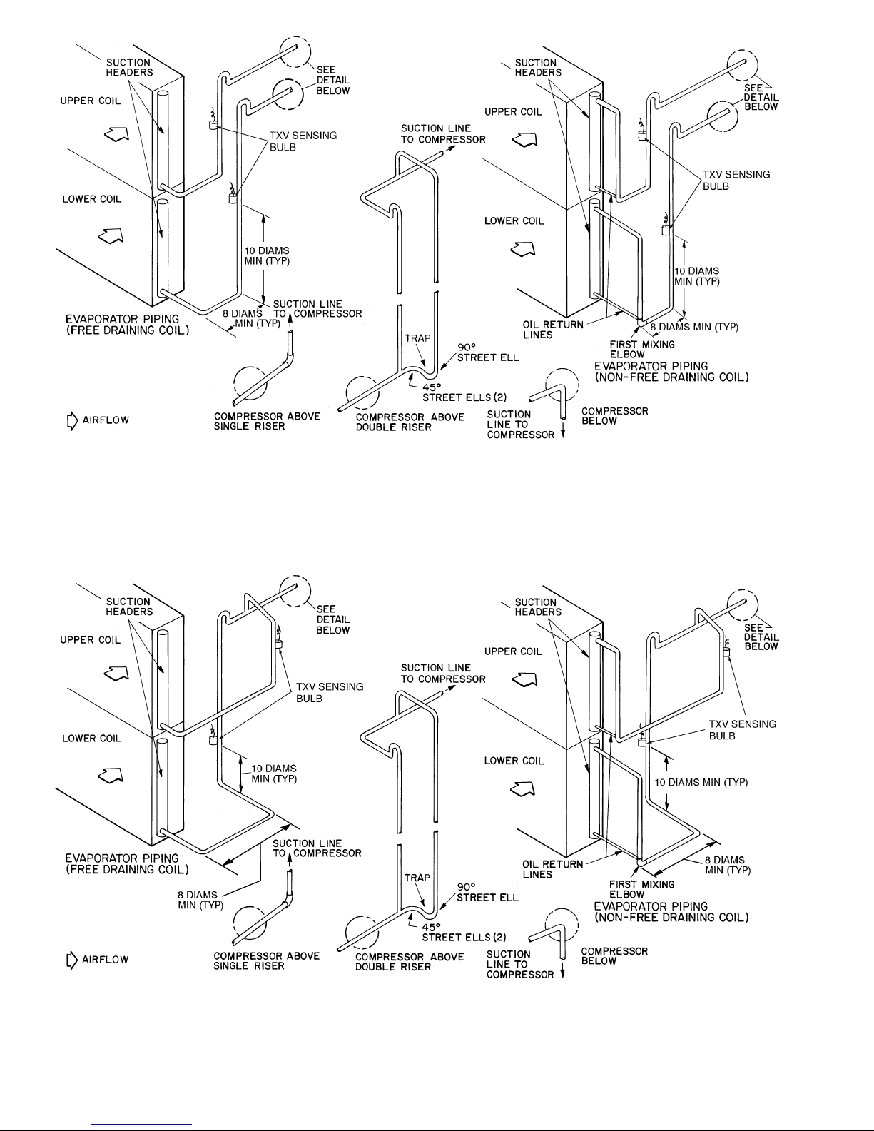
LEGEND
TXV — Thermostatic Expansion Valve
TYP — Typical
NOTE: Lower split first on, last off.
Fig. 14 — Typical Piping Connections for Face Split Coils for 38AH044-084 Dual-Circuit
and 38AH094-134 Units
LEGEND
TXV — Thermostatic Expansion Valve
TYP — Typical
NOTE: Lower split first on, last off.
Fig. 15 — Typical Piping Connections for Face Split Coils for 38AH044-084
Optional Single-Circuit Units
20
Page 21
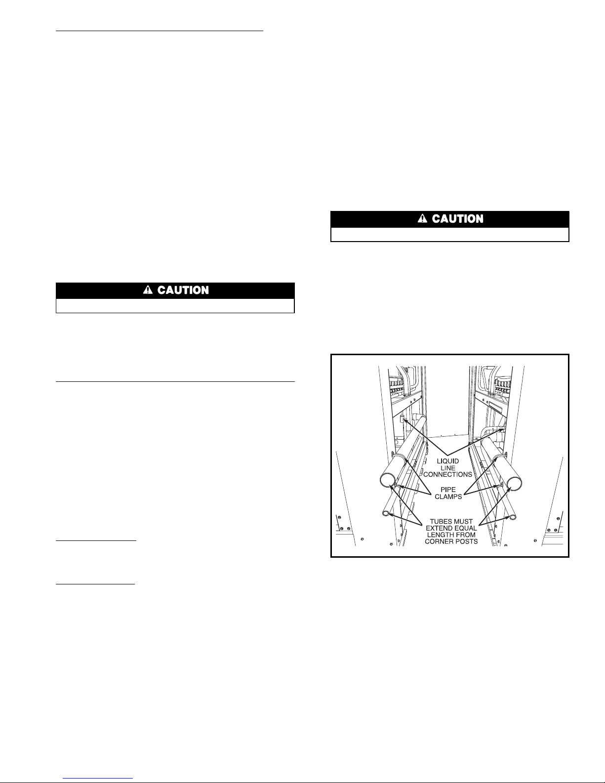
Units 38AH124 and 134 Piping Kit Connections — The
38AH124 and 134 units are delivered with a factorysupplied suction and liquid piping kit for installation in the
24-in. (610-mm) service space between the 2 unit modules.
The piping kit allows for a common unit side piping connection from the indoor unit to each of the condensing unit
refrigeration circuits. Fittings are provided and shipped in
the control box.
Remove the copper tubes from Module 124Aor134Acompressor rails. Save the pipe clamps for later use. Cut the
2
5
⁄8-in. (67-mm) suction tube into 2 pieces: 28 in. (711 mm)
and 67 in. (1702 mm). Connect the 2 formed 11⁄8-in.
(29-mm) tubes to the liquid line connection at the liquid valve.
See Fig. 16.
NOTE: Piping kit is designed to allow air handler connections to project from either side of the service space.
To prepare condensing unit modules for piping connection, refer to beginning paragraphs of Step 3 — Make
Refrigeration Piping Connections, page 14.
Two 2
5
⁄8-in. (67-mm) and one 11⁄8-in. (29-mm) elbows are
supplied for piping connections. Fit tubing to ensure proper
installation. All tubes should have equal lengths projecting
beyond unit corner posts. See Fig. 16. Ensure suction tube
is level for oil return requirements.
Protect liquid valves from the heat of brazing.
Braze the piping connections.
Level the tubes and clamp to the cornerpostswith factorysupplied self-drilling screws and pipe clamps removed from
Module 124A or 134A during piping kit removal.
Units 38AH124 and 134 Sheet Metal Trim Kit Installation
— After the units are in place and the piping kit is installed,
install the sheet metal trim kit.
NOTE: Install sheet metal trim kit before connection to air
handler tubing in case the modules must be repositioned to
accommodate the sheet metal installation.
Remove two 43-in. (1092 mm) base rail trim pieces from
Module 124A or 134A base rail. Remove the 3 corner post
bolts from the bottom of each corner post at the servicespace.
Align the base rail trim piece holes over the bolt holes in the
corner rails. See Fig. 17. Reinsert corner post bolts through
the trim piece into the corner posts.
Attach Top Cover — To attach top cover, proceed as
follows:
For Unit 38AH124, remove screws A from top of each of
4 corner posts at service space. See Fig. 18. Place cover on
top of service space and align top cover slots with corner
post screw holes. Reinsert screws A.
For Unit 38AH134, remove screws A from top of each corner post on Module 134A and screws B from top of each
corner post on Module 134B. See Fig. 18. Top cover is in
2 pieces: one vertical piece and one horizontal piece. Slide
vertical top cover partly under Module 134B end cover flange;
align holes and reinsert screws B. Place horizontal cover on
top of Module 134A end cover with opposite side resting on
the horizontal flange of the installed Module B vertical top
cover piece. Align holes on flange and top cover. Reinsert
screwsAthrough the top cover holes into the endcover. From
within the service space, insert supplied screws up through
the flange and horizontal cover to make a secure connection
between the horizontal and vertical cover pieces.
Insert supplied screws into each of the 2 holes in the vertical side flange of the top cover at each end of the service
space.
Attach Side Panels — Insert side panels at the ends of the
service space and hook side panel flange over the 2 screws
previously inserted in the top cover flange. Fasten panels to
the corner posts with supplied self-drilling screws, 3perside.
See Fig. 19.
Connect Tubing from Evaporator to Unit
Protect liquid valves from the heat of brazing.
Braze the liquid and suction lines from the evaporator to
the condensing unit liquid and suction lines. Leak test the
entire system by the pressure method described in the
Carrier Standard Service Techniques Manual, Chapter 1,
Section 1-6. Use R-22 at approximately 25 psig (172 kPa)
backed up with an inert gas to a total pressure not to exceed
245 psig (1689 kPa). If a leak is detected, evacuate and dehydrate the system. Follow methods described in the Carrier
Service Manual, Chapter 1, Section 1-7.
NOTES:
1. Ensure suction tube is level for oil return requirements.
2.
Protect liquid valves from heat of brazing.
Fig. 16 — Units 38AH124 and 134 with Installed
Piping Kit
21
Page 22
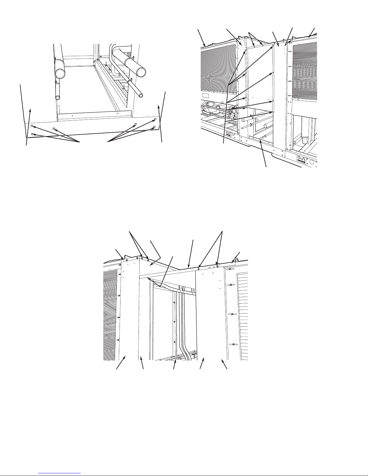
BASE RAIL
BOLTS (6)
CORNER POST
CORNER
POST
Fig. 17 — Units 38AH124 and 134 withInstalledT rim
Kit Rails
END COVER
FLANGES
SCREWS B
TOP COVER,
VERTICAL
PIECE
VERTICAL
TOP COVER
FLANGE
(HIDDEN)
SCREWS A
END COVER
TOP COVER,
HORIZONTAL
PIECE
CORNER
POST
MODULE 124B
OR 134B
24-in. (610-mm)
SERVICE WAY
CORNER
POST
MODULE 124A
OR 134A
Fig. 18 —Units 38AH124 and 134 with Installed Top
Cover (Unit 38AH134 Shown)
MODULE
124B
OR 134B
CORNER
POST (4 PER
MODULE)
SCREWS (2)
FOR
MOUNTING
SIDE PANEL
CORNER
POST
(4 PER
MODULE)
TOP
COVER
FLANGE
MODULE
124A
OR 134A
FACTORY-SUPPLIED
SELF-DRILLING
SCREWS (4 PER
CORNER POST)
24-in. (610-mm)
SERVICE WAY
Fig. 19 — Fully Assembled Piping and Trim Kit
(Unit 38AH134 Shown)
22
Page 23
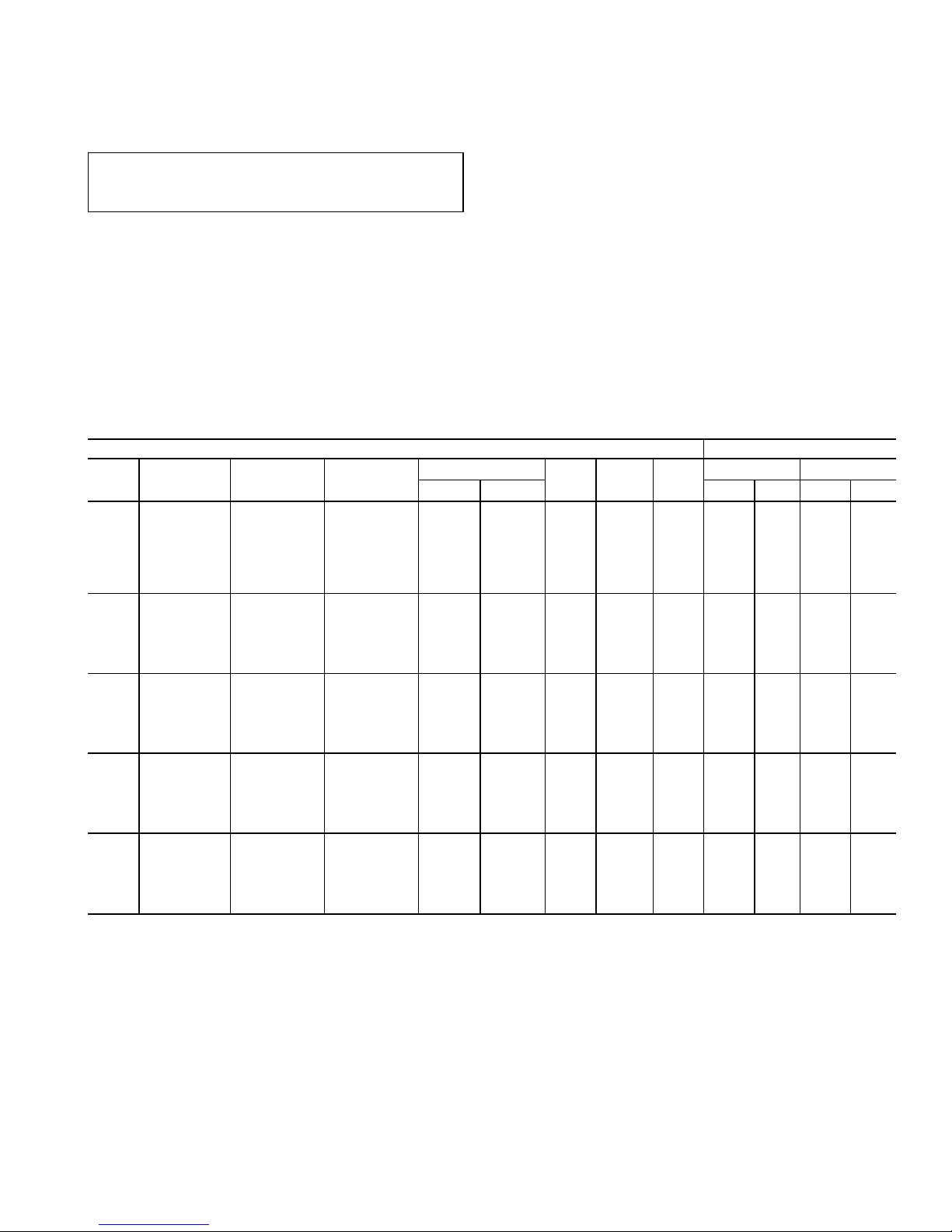
Step 4 — Make Electrical Connections
POWER SUPPLY — Electrical characteristics of available
power supply must agree with unit nameplate rating. Supply
voltage must be within the limits shown in Tables 10A or
10B, 11 and 12. See Table 13 for control circuit data and
Table 14 for fan motor electrical data.
IMPORTANT: Operation of unit on improper supply
voltage or with excessive phase imbalance constitutes
abuse and can affect any Carrier warranty.
FIELD POWER CONNECTIONS — All power wiring must
comply with applicable local and national codes. Install fieldsupplied, branch circuit safety disconnect(s) of a type that
can be locked off/open. Disconnects must be located within
sight of, and readily accessible from, the unit in compliance
with NEC (National Electrical Code) (U.S.A. Standard)
Article 440-14.
All field power enters the unit through a hole in the con-
trol box shelf. Refer to Fig. 20-28 for field wiring details.
MAIN POWER — Units 38AH044-104 have single-point
power connection to simplify field-power wiring (all power
enters at one end). Units 38AH124 and 134 require 2 connection points, one for each module. Units may use copper,
copper-clad aluminum, or aluminum conductors at all voltages. The maximum wire size units can accept per terminal
block is 500 kcmil.
Power must be supplied as shown in Table 15.
CONTROL CIRCUIT WIRING — Control circuit wiring is
accomplished with a step-down transformer on voltage designations 500, 600, and 100 in table below where the primary voltage is field voltage. For 208/230-v, 3-ph, 60-Hz
units, ensure that the transformer primary is wired properly
for the voltage which will be applied. All control wiring must
comply with applicable local and national codes. The safety
circuits are 24 v on all units. The safety circuit voltage is
created with a step-down transformer where main control
voltage is the transformer primary voltage.
See Table 13 for control circuit information.
Table 10A — Electrical Data — 50/60 Hz (38AH044-084 Dual-Circuit Units)
STANDARD UNIT COMPRESSOR*
38AH
Voltage
Designation
Compressor
A1/B1
Model No.
Nameplate
V-Ph-Hz
Supply Voltage†
MCA MOCP ICF
A1 B1
Min Max RLA LRA RLA LRA
044
500
06E4250/250
208/230-3-60 187 254 179.4 225 434.7 67.9 345 67.9 345
600 460-3-60 414 508 91.3 100 218.6 34.6 173 34.6 173
100 575-3-60 518 632 78.4 100 162.4 28.8 120 28.8 120
200 380-3-60 342 418 93.5 125 241.2 34.6 191 34.6 191
800 (PW) 230-3-50 198 254 180.2 225 296.7 67.9 207 67.9 207
900 380/415-3-50 342 440 91.5 100 219.6 34.6 173 34.6 173
300 (PW) 346-3-50 325 367 100.0 125 165.9 33.3 115 33.3 115
054
500
06E4250/265
208/230-3-60 187 254 206.6 250 535.7 67.9 345 89.7 446
600 460-3-60 414 508 102.4 125 268.6 34.6 173 43.6 223
100 575-3-60 518 632 88.0 125 206.4 28.8 120 36.5 164
200 380-3-60 342 418 107.1 150 297.2 34.6 191 45.5 247
900 380/415-3-50 342 440 102.7 125 269.6 34.6 173 43.6 223
300 (PW) 346-3-50 325 367 107.0 150 198.9 33.3 115 44.9 148
064
500
06E8265/275
208/230-3-60 187 254 249.3 350 617.5 89.7 446 106.4 506
600 460-3-60 414 508 115.5 150 307.6 43.6 223 46.8 253
100 575-3-60 518 632 100.6 125 226.1 36.5 164 40.4 176
200 380-3-60 342 418 126.9 175 341.1 45.5 247 52.6 280
900 380/415-3-50 342 440 114.1 150 335.6 43.6 223 46.8 280
300 (PW) 346-3-50 325 367 129.8 175 230.5 44.9 148 53.8 168
074
500
06E8275/299
208/230-3-60 187 254 330.5 450 829.0 106.4 506 147.4 690
600 460-3-60 414 508 148.6 200 408.2 46.8 253 65.4 345
100 575-3-60 518 632 132.2 175 336.8 40.4 176 57.1 276
200 380-3-60 342 418 174.5 250 458.0 52.6 280 78.8 382
900 380/415-3-50 342 440 143.0 200 403.8 46.8 280 65.4 345
300 (PW) 346-3-50 325 367 170.8 250 300.4 53.8 168 79.5 229
084
500
06E8299/299
208/230-3-60 187 254 371.5 500 870.0 147.4 690 147.4 690
600 460-3-60 414 508 167.2 225 426.8 65.4 345 65.4 345
100 575-3-60 518 632 148.9 200 353.5 57.1 276 57.1 276
200 380-3-60 342 418 200.7 250 484.2 78.8 382 78.8 382
900 380/415-3-50 342 440 167.6 225 428.4 65.4 345 65.4 345
300 (PW) 346-3-50 325 367 205.3 250 334.9 79.5 229 79.5 229
See page 24 for Legend and Notes.
23
Page 24
Table 10B — Electrical Data — 50/60 Hz (38AH044-084 Optional Single-Circuit Units)
OPTIONAL SINGLE-CIRCUIT UNIT COMPRESSOR*
38AH
Voltage
Designation
Compressor
A1/A2
Model No.
Nameplate
V-Ph-Hz
Supply Voltage
MCA MOCP ICF
A1 A2
Min Max RLA LRA RLA LRA
044
500
06E4250/250
208/230-3-60 187 254 179.4 225 434.7 67.9 345 67.9 345
600 460-3-60 414 508 91.3 100 218.6 34.6 173 34.6 173
100 575-3-60 518 632 78.4 100 162.4 28.8 120 28.8 120
200 380-3-60 342 418 93.5 125 241.2 34.6 191 34.6 191
800 (PW) 230-3-50 198 254 180.2 225 296.7 67.9 207 67.9 207
900 380/415-3-50 342 440 91.5 100 219.6 34.6 173 34.6 173
300 (PW) 346-3-50 325 367 100.0 125 165.9 33.3 115 33.3 115
054
500
06E4265/250
208/230-3-60 187 254 206.6 250 535.7 89.7 446 67.9 345
600 460-3-60 414 508 102.4 125 268.6 43.6 223 34.6 173
100 575-3-60 518 632 88.0 125 206.4 36.5 164 28.8 120
200 380-3-60 342 418 107.1 150 297.2 45.5 247 34.6 191
900 380/415-3-50 342 440 102.7 125 269.6 43.6 223 34.6 173
300 (PW) 346-3-50 325 367 107.0 150 198.9 44.9 148 33.3 115
064
500
06E8275/265
208/230-3-60 187 254 249.3 350 617.5 106.4 506 89.7 446
600 460-3-60 414 508 115.5 150 307.6 46.8 253 43.6 223
100 575-3-60 518 632 100.6 125 226.1 40.4 176 36.5 164
200 380-3-60 342 418 126.9 175 341.1 52.6 280 45.5 247
900 380/415-3-50 342 440 115.7 150 335.6 46.8 280 43.6 223
300 (PW) 346-3-50 325 367 129.8 175 230.5 53.8 168 44.9 148
074
500
06E8299/275
208/230-3-60 187 254 330.5 450 829.0 147.4 690 106.4 506
600 460-3-60 414 508 148.6 200 408.2 65.4 345 46.8 253
100 575-3-60 518 632 132.2 175 336.8 57.1 276 40.4 176
200 380-3-60 342 418 174.5 250 458.0 78.8 382 52.6 280
900 380/415-3-50 342 440 143.0 200 403.8 65.4 345 46.8 280
300 (PW) 346-3-50 325 367 170.8 250 300.4 79.5 229 53.8 168
084
500
06E8299/299
208/230-3-60 187 254 371.5 500 870.0 147.4 690 147.4 690
600 460-3-60 414 508 167.2 225 426.8 65.4 345 65.4 345
100 575-3-60 518 632 148.9 200 353.5 57.1 276 57.1 276
200 380-3-60 342 418 200.7 250 484.2 78.8 382 78.8 382
900 380/415-3-50 342 440 167.6 225 428.4 65.4 345 65.4 345
300 (PW) 346-3-50 325 367 205.3 250 334.9 79.5 229 79.5 229
LEGEND
FLA — Full Load Amps
ICF — Maximum Instantaneous Current Flow During Starting.
(The point in the starting sequence where the sum of
the LRAforthestartingcompressors,plusthetotalRLA
for all running compressors, plus the FLA for all running
fan motors is maximum.)
kcmil — Thousand Circular Mils
LRA — Locked Rotor Amps
Max — Maximum
MCA — Minimum Circuit Amps (used for sizing; complies with
National Electrical Code [NEC] [U.S.A. Standard],
section 430-24).
Min — Minimum
MOCP — Maximum Overcurrent Protection (used for sizing dis-
connect; complies with NEC Article 440, Section 22).
RLA — Rated Load Amps
PW — Part Wind Only
*All compressors are across-the-line start only except 38AH044
230 v, 3-phase, 50 Hz; and all 346 v, 3-phase, 50 Hz.
†Units are suitable for use on electrical systems where voltage sup-
plied to unit terminals is within listed minimum to maximum limits.
NOTES:
1. Maximum allowable phase imbalance: voltage - 2%; amps - 10%.
2. Maximum incoming wire size for terminal block is 500 kcmil.
24
Page 25
Table 11 — Electrical Data — 50/60 Hz (Units 38AH094,104)
UNIT
38AH
VOLTAGE
DESIGNATION
NAMEPLATE
V-Ph-Hz
SUPPLY
VOLTAGE*
MCA MOCP ICF
COMPRESSOR†
A1 A2 B1 B2
Min Max RLA LRA RLA LRA RLA LRA RLA LRA
094
500 208/230-3-60 187 253 398.5 500 897 106.4 506 67.9 345 147.7 690 — —
600 460-3-60 414 506 183.1 225 443 46.8 253 34.6 173 65.4 345 — —
100 575-3-60 518 633 160.9 200 366 40.4 176 28.8 120 57.1 276 — —
200 380-3-60 342 418 209.1 250 493 52.6 280 34.6 191 78.8 382 — —
900 380/415-3-50 342 440 183.6 225 444 46.8 280 34.6 173 65.4 345 — —
300 (PW) 346-3-50 325 380 212.9 250 343 53.8 168 33.3 115 79.5 229 — —
104
500 208/230-3-60 187 253 399.4 450 722 89.7 446 67.9 345 89.7 446 89.7 446
600 460-3-60 414 506 196.3 225 361 43.6 223 34.6 173 43.6 223 43.6 223
100 575-3-60 518 633 168.0 200 286 36.5 164 28.8 120 36.5 164 36.5 164
200 380-3-60 342 418 205.9 250 396 45.5 247 34.6 191 45.5 247 45.5 247
900 380/415-3-50 342 440 196.7 225 363 43.6 223 34.6 173 43.6 223 43.6 223
300 (PW) 346-3-50 325 380 205.6 250 298 44.9 148 33.3 229 44.9 148 49.9 148
LEGEND
——Not Applicable
FLA — Full Load Amps
ICF — Maximum Instantaneous Current Flow During Starting.
(The point in the starting sequence where the sum of
the LRAforthestartingcompressors,plusthetotalRLA
for all running compressors, plus the FLA for all running
fan motors is maximum.)
kcmil — Thousand Circular Mils
LRA — Locked Rotor Amps
MCA — Minimum Circuit Amps (used for sizing; complies with
National Electrical Code [NEC] [U.S.A. Standard],
section 430-24).
MOCP — Maximum Overcurrent Protection (used for sizing
disconnect; complies with NEC [U.S.A. Standard],
section 440-22).
RLA — Rated Load Amps
*Units are suitable for use on electrical systems where voltage sup-
plied to unit terminals is within listed minimum to maximum limits.
†All compressors are across-the-line start only except 346-V, 3-ph,
50-Hz units.
NOTES:
1. Maximum allowable phase imbalance: voltage - 2%; amps - 10%.
2. Maximum incoming wire size for terminal block is 500 kcmil.
3. For units 38AH094and104 compressor modelnumbers,see table
below:
UNIT
38AH
094 104
CKT A1 A2 B1 A1 A2 B1 B2
MODEL
NO. 06E
−275 −250 −299 −265 −250 −265 −265
25
Page 26
Table 12 — Electrical Data — 50/60 Hz (Units 38AH124, 134)
UNIT
38AH
MODULE
VOLTAGE
DESIGNATION
COMPRESSOR
A1/A2
MODEL NO.
NAMEPLATE
V-Ph-Hz
SUPPLY
VOLTAGE*
MCA MOCP ICF
COMPRESSOR†
A1 A2
Min Max RLA LRA RLA LRA
124A
124B
134A
500
06E8275/
265
208/230-3-60 187 254 249.3 350 617.5 106.4 506 89.7 446
600 460-3-60 414 508 115.5 150 307.6 46.8 253 43.6 223
100 575-3-60 518 632 100.6 125 226.1 40.4 176 36.5 164
200 380-3-60 342 418 126.9 175 341.1 52.6 280 45.5 247
900 380/415-3-50 342 440 115.7 150 335.6 46.8 280 43.6 223
300 (PW) 346-3-50 325 367 129.8 175 230.5 53.8 168 44.9 148
134B
500
06E8299/
275
208/230-3-60 187 254 330.5 450 829.0 147.4 690 106.4 506
600 460-3-60 414 508 148.6 200 408.2 65.4 345 46.8 253
100 575-3-60 518 632 132.2 175 336.8 57.1 276 40.4 176
200 380-3-60 342 418 174.5 250 458.0 78.8 382 52.6 280
900 380/415-3-50 342 440 149.0 200 403.8 65.4 345 46.8 280
300 (PW) 346-3-50 325 367 170.8 250 300.4 79.5 229 53.8 168
LEGEND
FLA — Full Load Amps
ICF — Maximum Instantaneous Current Flow During Starting.
(The point in the starting sequence where the sum of
the LRAforthestartingcompressors,plusthetotalRLA
for all running compressors, plus the FLA for all running
fan motors is maximum.)
kcmil — Thousand Circular Mils
LRA — Locked Rotor Amps
MCA — Minimum Circuit Amps (used for sizing; complies with
National Electrical Code [NEC] [U.S.A. Standard],
section 430-24).
MOCP — Maximum Overcurrent Protection (used for sizing
disconnect; complies with NEC [U.S.A. Standard],
section 440- 22).
PW — Part Wind
RLA — Rated Load Amps
*Units are suitable for use on electrical systems where voltage sup-
plied to unit terminals is within listed minimum to maximum limits.
†All compressors are across-the-line start only except 346-v, 3-ph,
50 Hz unit.
NOTES:
1. Maximum allowable phase imbalance: voltage - 2%; amps - 10%.
2. Maximum incoming wire size for terminal block is 500 kcmil.
Table 13 — Control Circuit Electrical Data — 50/60 Hz
UNIT
DESIGNATION
UNIT POWER CONTROL POWER
AMPS
V-Ph-Hz V-Ph-Hz Min Max
−500 208/230-3-60 115-1-60 103 127 4.1
−600 460-3-60 115-1-60 103 127 4.1
−100 575-3-60 115-1-60 103 127 4.1
−200 380-3-60 230-1-60 207 253 2.0
−800 230-3-50 230-1-50 207 253 2.0
−900 380/415-3-50 230-1-50 207 253 2.0
−300 346-3-50 200-1-50 180 220 2.4
NOTE: Units 38AH124 and 134 have 2 control boxes per unit, one in each module.
26
Page 27
Table 14 — Fan Motor Electrical Data
UNIT
38AH
CONDENSER FAN
Nameplate
V-Ph-Hz
Qty
Hp
(kW)
Total
kW
(No.*) FLA Each (No.*) LRA Each
044
208/230-3-60
4
1
(0.746)
6.2
(1,2) 5.5 (3,4) 6.6 (1,2) 30.0 (3,4) 31.6
460-3-60 (1,2) 2.8 (3,4) 3.3 (1,2) 30.0 (3,4) 31.6
575-3-60 (1-4) 3.4 (1-4) 30.0
380-3-60 (1-4) 3.9 (1-4) 20.9
230-3-50 (1,2) 5.5 (3,4) 6.8 (1,2) 30.0 (3,4) 31.6
380/415-3-50 (1-4) 3.4 (1-4) 30.0
346-3-50 (1-4) 4.4 (1-4) 20.9
054
208/230-3-60
4
1
(0.746)
6.2
(1,2) 5.5 (3,4) 6.6 (1,2) 30.0 (3,4) 31.6
460-3-60 (1,2) 2.8 (3,4) 3.3 (1,2) 30.0 (3,4) 31.6
575-3-60 (1-4) 3.4 (1-4) 30.0
380-3-60 (1-4) 3.9 (1-4) 20.9
380/415-3-50 (1-4) 3.4 (1-4) 30.0
346-3-50 (1-4) 4.4 (1-4) 20.9
064
208/230-3-60
4
1
(0.746)
6.2
(1,2) 5.5 (3,4) 6.6 (1,2) 30.0 (3,4) 31.6
460-3-60 (1,2) 2.8 (3,4) 3.3 (1,2) 30.0 (3,4) 31.6
575-3-60 (1-4) 3.4 (1-4) 30.0
380-3-60 (1-4) 3.9 (1-4) 20.9
380/415-3-50 (1-4) 3.4 (1-4) 30.0
346-3-50 (1-4) 4.4 (1-4) 20.9
074
208/230-3-60
6
1
(0.746)
9.3
(1,2) 5.5 (3-6) 6.6 (1,2) 30.0 (3-6) 31.6
460-3-60 (1,2) 2.8 (3-6) 3.3 (1,2) 30.0 (3-6) 31.6
575-3-60 (1-6) 3.4 (1-6) 30.0
380-3-60 (1-6) 3.9 (1-6) 20.9
380/415-3-50 (1-6) 3.4 (1-6) 30.0
346-3-50 (1-6) 4.4 (1-6) 20.9
084
208/230-3-60
6
1
(0.746)
9.3
(1,2) 5.5 (3-6) 6.6 (1,2) 30.0 (3-6) 31.6
460-3-60 (1,2) 2.8 (3-6) 3.3 (1,2) 30.0 (3-6) 31.6
575-3-60 (1-6) 3.4 (1-6) 30.0
380-3-60 (1-6) 3.9 (1-6) 20.9
380/415-3-50 (1-6) 3.4 (1-6) 30.0
346-3-50 (1-6) 4.4 (1-6) 20.9
094
208/230-3-60
6
1
(0.746)
9.4
(1,2) 5.5 (3-6) 6.6 (1,2) 30.0 (3-6) 31.6
460-3-60 (1-2) 2.8 (3-6) 3.3 (1,2) 30.0 (3-6) 31.6
575-3-60 (1-6) 3.4 (1-6) 30.0
380-3-60 (1-6) 3.9 (1-6) 20.9
380/415-3-50 (1-6) 3.4 (1-6) 30.0
346-3-50 (1-6) 4.4 (1-6) 20.9
104
208/230-3-60
6
1
(0.746)
9.5
(1,2) 5.5 (3-6) 6.6 (1,2) 30.0 (3-6) 31.6
460-3-60 (1,2) 2.8 (3-6) 3.3 (1,2) 30.0 (3-6) 31.6
575-3-60 (1-6) 3.4 (1-6) 30.0
380-3-60 (1-6) 3.9 (1-6) 20.9
380/415-3-50 (1-6) 3.4 (1-6) 30.0
346-3-50 (1-6) 4.4 (1-6) 20.9
UNIT 38AH
MODULE
124A
124B
134A
208/230-3-60
4
1
(0.746)
6.4
(1,2) 5.5 (3,4) 6.6 (1,2) 30.0 (3,4) 31.6
460-3-60 (1,2) 2.8 (3,4) 3.3 (1,2) 30.0 (3,4) 31.6
575-3-60 (1-4) 3.4 (1-4) 30.0
380-3-60 (1-4) 3.9 (1-4) 20.9
380/415-3-50 (1-4) 3.4 (1-4) 30.0
346-3-50 (1-4) 4.4 (1-4) 20.9
134B
208/230-3-60
6
1
(0.746)
9.2
(1,2) 5.5 (3-6) 6.6 (1,2) 30.0 (3-6) 31.6
460-3-60 (1,2) 2.8 (3-6) 3.3 (1,2) 30.0 (3-6) 31.6
575-3-60 (1-6) 3.4 (1-6) 30.0
380-3-60 (1-6) 3.9 (1-6) 20.9
380/415-3-50 (1-6) 3.4 (1-6) 30.0
346-3-50 (1-6) 4.4 (1-6) 20.9
LEGEND
FLA — Full Load Amps
LRA — Locked Rotor Amps
*Refers to condenser fans by position: See circled numbers on top
views of units in Fig. 1-6.
NOTE: All fans are protected by a single circuit breaker.
27
Page 28
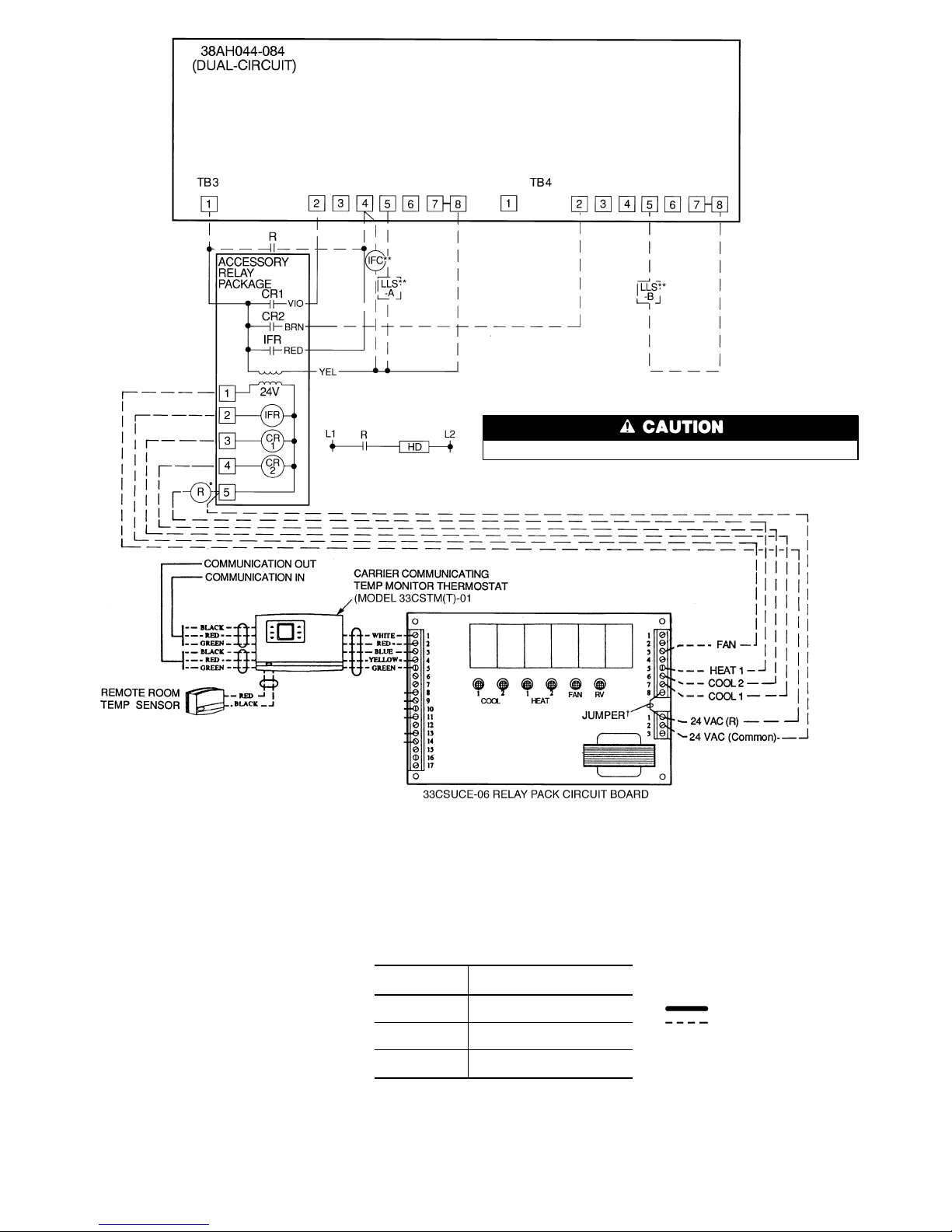
LEGEND
AWG — American Wire Gage
CR — Control Relay
HD — Heating Device
IFC — Indoor-Fan Contactor
IFR — Indoor-Fan Relay
kcmil — Thousand Circular Mils
LLS — Liquid Line Solenoid
NEC — National Electrical Code
(U.S.A. Standard)
R—Heating Relay (field-
supplied 24-v sealed coil,
10 va maximum rating)
RV — Reversing Valve
TB — Terminal Block
Factory Wiring
Field Wiring
Internal 33CSUCE-06relay contacts are ratedfor1 amp/24 vac.
*To control heatingdevice andprovide automaticindoor-
fan operation on heating.
†Jumper removed only when separate 24-v trans-
formerpowersource isused topower the33CSUCE-06
relay pack.
**Field-supplied.
NOTES:
1. Liquid linesolenoid valve LLS-Aisusedfor solenoiddropon circuitA. Liquidlinesolenoid valve
LLS-B is used for solenoid drop for circuit B.
2. Solenoid drop is a safety feature which preventsrefrigerantmigration tothecompressor during the OFF cycle. It is recommended on all
systems andrequiredonsystems where piping
exceeds 75 ft (22.9 m) in length.
3. The 33CSUCE-06 relay pack requires 10 va.
4. Factory wiring is in accordance with NEC; field
modifications or additions must be in compliance with all applicable codes.
5. Wiring for field power supply must be rated
75 Cminimum.Usecopper, copper-clad aluminum, or aluminum conductors. Maximum incoming wire size for each terminal block is
500 kcmil.
6. Terminal blocks TB3 and TB4 are for external
field control connections. Control connections
are to be Class 1 wiring.
7. Field-supplied components (IFC, LLS-A, and
LLS-B) must have a maximum sealed coil rating of 30 va each (0.25 amp at 120 vac and
Fig. 20 — Field Wiring, One 2-Stage Thermostat — 38AH044-084 Dual-Circuit Units
0.13 amp at 230 vac). Thermostats must have a
minimum pilot duty rating of 300 va (2.5 amps at
120 vac and 1.3 amps at 230 vac).
8. Replacement of factory wires must be with type
105 C wire or its equivalent.
9. Field-supplied liquid line solenoid valves installed
at the evaporator are required on all units.
10. Units have 175 va of power available for fieldinstalled accessories.
11. To minimize voltage drop, the following wire sizes
are recommended:
LENGTH —
Ft (M)
INSULATED WIRE — AWG
(35 C Minimum)
Up to 50
(15.2)
No. 18
50-75
(15.2-22.9)
No. 16
More Than 75
(22.9)
No. 14
28
Page 29
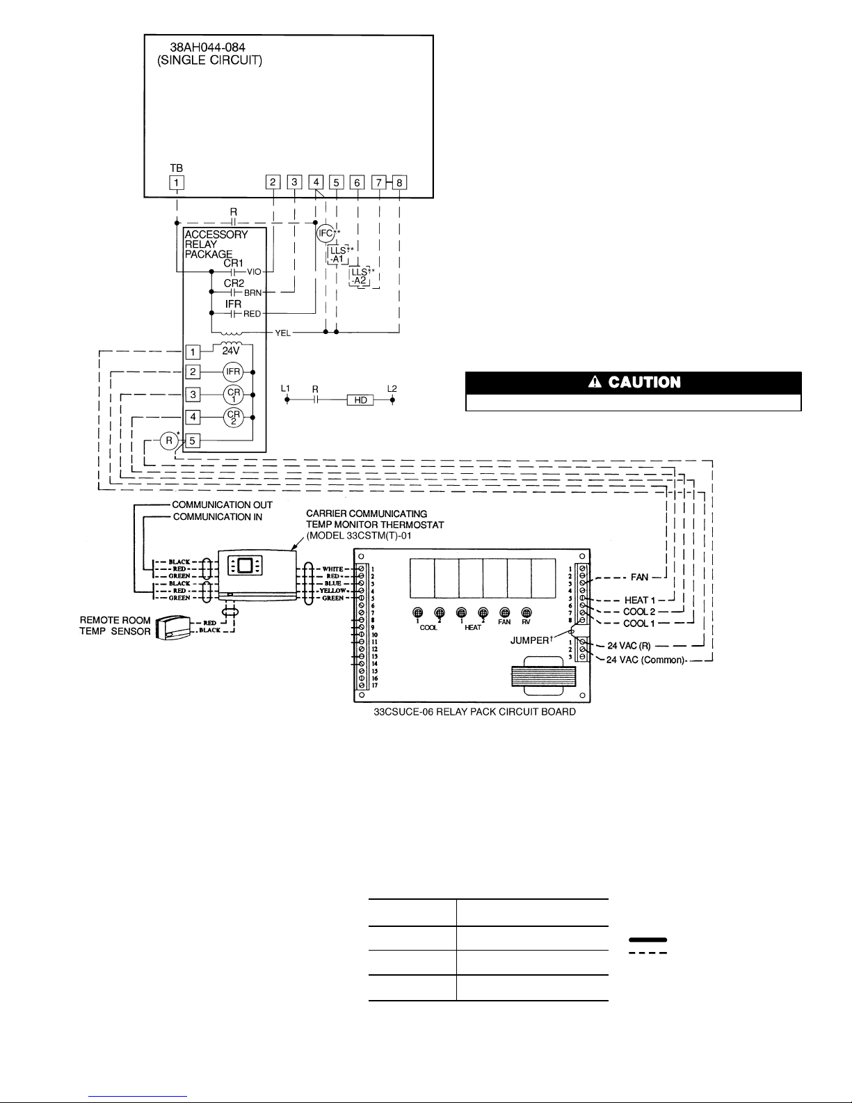
LEGEND
AWG — American Wire Gage
CR — Control Relay
HD — Heating Device
IFC — Indoor-Fan Contactor
IFR — Indoor-Fan Relay
kcmil — Thousand Circular Mils
LLS — Liquid Line Solenoid
NEC — National Electrical Code
(U.S.A. Standard)
R—Heating Relay (field-
supplied 24-v sealed coil,
10 va maximum rating)
RV — Reversing Valve
TB — Terminal Block
Factory Wiring
Field Wiring
*To control heatingdevice andprovide automaticindoor-
fan operation on heating.
†Jumper removed only when separate 24-v trans-
formerpowersource isused topower the33CSUCE-06
relay pack.
**Field-supplied.
NOTES:
1. Liquid linesolenoid valves LLS-A1and A2are used
for solenoid drops.
2. Solenoid drop is a safety feature which prevents
refrigerant migration to the compressor during
the OFF cycle. It is recommended on all systems
and required on systems where piping exceeds
75 ft (22.9 m) in length.
3. The 33CSUCE-01 relay pack requires 10 va.
4. Factory wiringis inaccordance with NEC;field modifications or additions must be in compliance with
all applicable codes.
5. Wiring for field power supply must be rated 75 C
minimum. Use copper, copper-clad aluminum, or
aluminumconductors.Maximum incomingwire size
for each terminal block is 500 kcmil.
6. Terminal blocks are for external field control connections. Control connections are to be Class 1
wiring.
7. Field-supplied components (IFC, LLS-A1, and
LLS-A2) must have a maximum sealed coil rating
of 30 va each (0.25 amp at 120 vac and 0.13 amp
Fig. 21 — Field Wiring, One 2-Stage Thermostat — 38AH044-084 Optional Single-Circuit Units
Internal 33CSUCE-06 relay contacts are rated for 1 amp/24 vac.
at 230 vac).Thermostats must have a minimum pilot
duty rating of 300 va (2.5 amps at 120 vac and
1.3 amps at 230 vac).
8. Replacement of factory wires must be with type
105 C wire or its equivalent.
9. Field-supplied liquid line solenoid valves installed at
the evaporator are required on all units.
10. Units have 175 va of power available for fieldinstalled accessories.
11. Tominimize voltage drop,the following wiresizes are
recommended:
LENGTH —
Ft (M)
INSULATED WIRE — AWG
(35 C Minimum)
Up to 50
(15.2)
No. 18
50-75
(15.2-22.9)
No. 16
More Than 75
(22.9)
No. 14
29
Page 30
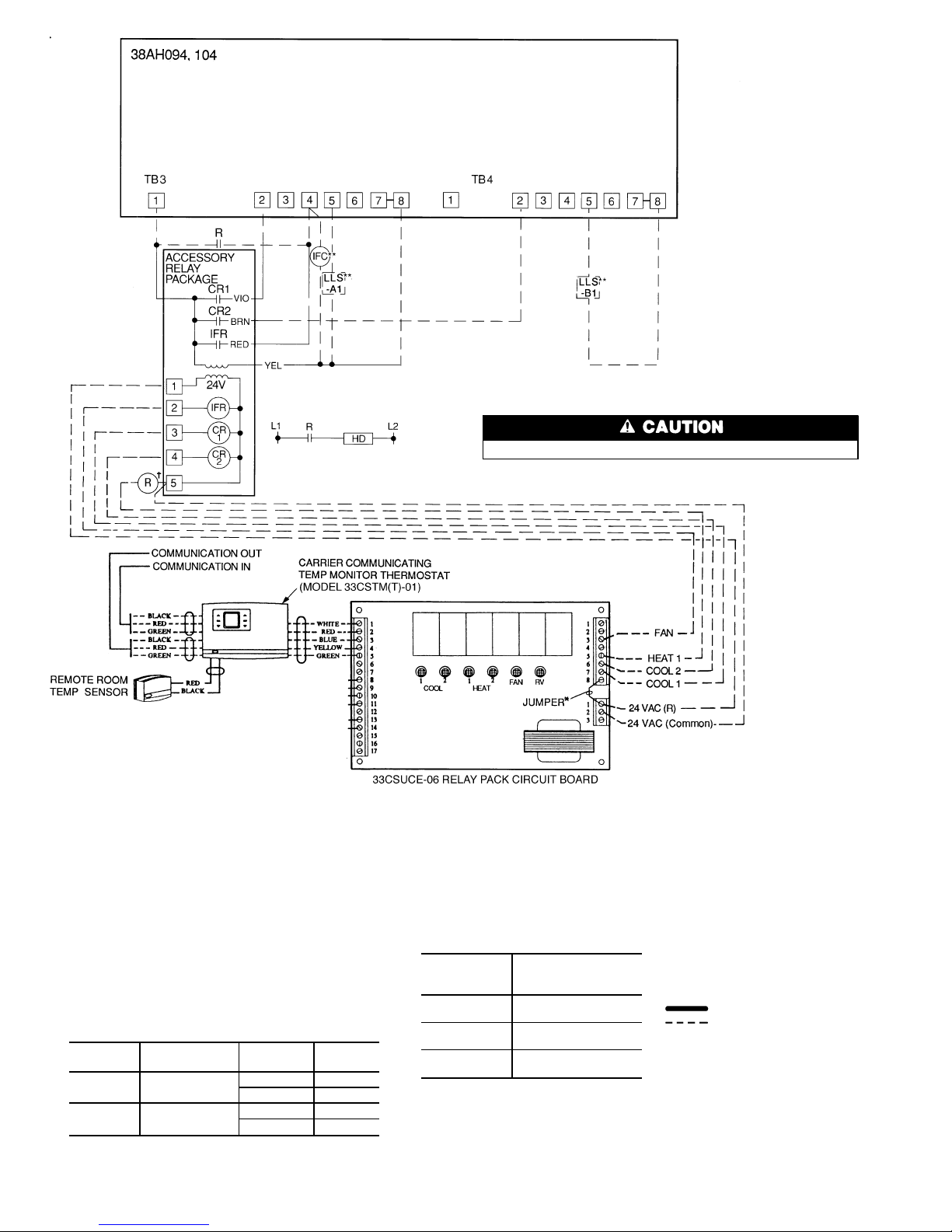
LEGEND
AWG — American Wire Gage
CR — Control Relay
HD — Heating Device
IFC — Indoor-Fan Contactor
IFR — Indoor-Fan Relay
kcmil — Thousand Circular Mils
LLS — Liquid Line Solenoid
NEC — National Electrical Code
(U.S.A. Standard)
R—Heating Relay (field-
supplied 24-v sealed coil,
10 va maximum rating)
RV — Reversing Valve
TB — Terminal Block
Factory Wiring
Field Wiring
*To control heatingdevice andprovide automaticindoor-
fan operation on heating.
†Jumper removed only when separate 24-v trans-
formerpowersource isused topower the33CSUCE-06
relay pack.
**Field-supplied.
Internal 33CSUCE-06 relay contacts are rated for 1 amp/24 vac.
NOTES:
1. Liquid line solenoid valve LLS-A1 is used for solenoid drop
on circuit A. Liquid line solenoid valve LLS-B1 is used for
solenoid drop for circuit B.
2. Solenoid drop is a safety feature which prevents refrigerant
migration to the compressor during the OFF cycle. It is recommended on all systems and required on systems where
piping exceeds 75 ft (22.9 m) in length.
3. The 33CSUCE-06 relay pack requires 10 va.
4. Factory wiring is in accordance with NEC; field modifications
or additions must be in compliance with all applicable codes.
5. Wiring for field power supply must be rated 75 C minimum. Use copper, copper-clad aluminum, or aluminum conductors. Maximumincomingwire size for eachterminalblock
is 500 kcmil.
6. Terminalblocks arefor external fieldcontrol connections.Control connections must be Class 1 wiring.
7. Field-supplied components (IFC, LLS-A1, and LLS-B1) must
have a maximum sealed coil rating of 30 va each (0.25 amp
at 120vac and 0.13ampat 230 vac).Thermostats must have
a minimum pilot duty rating as follows:
38AH
VA
(Ea Stage)
AMPS VAC
094 275
2.29 120
1.15 240
104 325
2.70 120
1.35 240
8. Replacement of factory wires must be with
type 105 C wire or its equivalent.
9. Field-supplied liquidlinesolenoid valves installed at theevaporatorare required on all
units.
10. Units 38AH094has 140va andunit 38AH104
has 130 va of power available for fieldinstalled accessories.
11. Tominimize voltage drop,the following wire
sizes are recommended:
LENGTH —
Ft (M)
INSULATED WIRE —
AWG
(35 C Minimum)
Up to 50
(15.2)
No. 18
50-75
(15.2-22.9)
No. 16
More Than 75
(22.9)
No. 14
Fig. 22 — Field Wiring, One 2-Stage Thermostat — Units 38AH094 and 104
30
Page 31
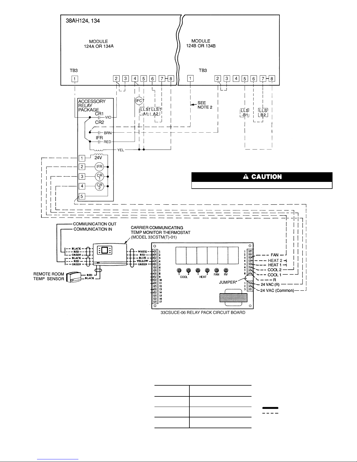
LEGEND
AWG — American Wire Gage
C—Compressor Contactor
CCPS — Capacity Control Pressure
Switch
CR — Control Relay
HD — Heating Device
IFC — Indoor-Fan Contactor
IFR — Indoor-Fan Relay
kcmil — Thousand Circular Mils
LLS — Liquid Line Solenoid
NEC — National Electrical Code
(U.S.A. Standard)
R—Heating Relay (field-
supplied 24-v sealed coil,
10 va maximum rating)
RV — Reversing Valve
SDR — Solenoid Drop Relay
TB — Terminal Block
TR — Timer Relay
Factory Wiring
Field Wiring
*Jumper removed only when separate 24-v trans-
formerpowersource isused topowerthe 33CSUCE-06
relay pack.
†Field-supplied.
Internal 33CSUCE-06 relay contacts are rated for 1 amp/24 vac.
Fig. 23 — Field Wiring, One 2-Stage Thermostat — Units 38AH124 and 134
NOTES:
1. Liquid linesolenoid valves LLS-A1and A2are used
for solenoid drop on Module 124A or 134A on circuit A. Liquid line solenoid valves LLS-B1 and B2
areusedfor solenoiddrop forModule124B or134B.
Solenoid drop is a safety feature which prevents
refrigerant migration to the compressor during
the OFF cycle. It is recommended on all systems
and required on systems where piping exceeds
75 ft (22.9 m) in length.
2. Disconnectblackwire fromCR2 terminal 6;cap loose
end and secure. Connect new field-supplied wire
from CR2 terminal 6 to TB3 terminal 1 on module
124B or 134B.
3. The 33CSUCE-06 relay pack requires 10 va.
4. Factory wiringis inaccordance with NEC;field modifications or additions must be in compliance with
all applicable codes.
5. Wiring for field power supply must be rated 75 C
minimum. Use copper, copper-clad aluminum, or
aluminumconductors.Maximum incomingwire size
for each terminal block is 500 kcmil.
6. Terminalblocks (TB3) are for external field control
connections. Control connections must be Class1
wiring.
7. Field-supplied components (IFC, LLS-A1,A2, and
LLS-B1,B2) must have a maximum sealed coil
rating of 30 va each (0.25 amp at 120 vac and
0.13 amp at 230 vac). Thermostats must have a
minimum pilot duty rating of 300 va (2.5 amps at
120 vac).
8. Replacement of factory wires must be with type
105 C wire or its equivalent.
9. Field-supplied liquid line solenoid valves installed
at the evaporator are required on all units.
10. Units have 175 va of power available for fieldinstalled accessories.
11. To minimize voltage drop, the following wire sizes
are recommended:
LENGTH —
Ft (M)
INSULATED WIRE — AWG
(35 C Minimum)
Up to 50
(15.2)
No. 18
50-75
(15.2-22.9)
No. 16
More Than 75
(22.9)
No. 14
31
Page 32
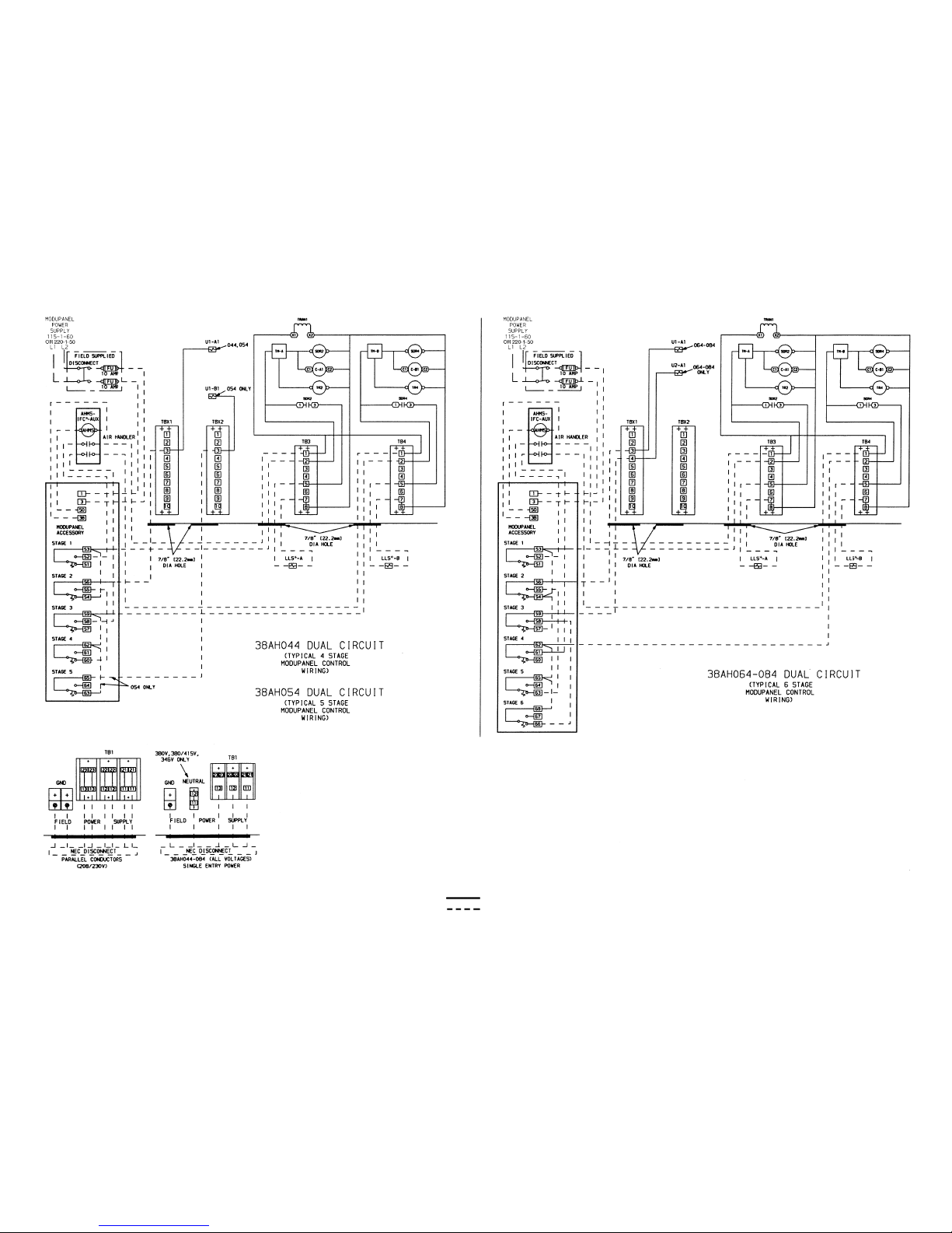
*Field-supplied.
NOTES:
1. Factory wiring is in accordance with NEC; field modifications or additions must be in compliance with all applicable codes.
2. Wiring for field power supply must be rated 75 C minimum. Use copper, copper-clad aluminum, or aluminum conductors. Maximum
incoming wire size for each terminal block is 500 kcmil.
3. Terminal blocks TB3 and TB4 are for external field control connections. Control connections are to be Class 1 wiring.
4. Field-supplied components (IFC,LLS-A, and LLS-B)must have amaximum sealedcoil rating of30 va each (.25 amp at 120 vac, .13 amp at
230 vac). AHMS IFC-AUX must have a minimum pilot duty rating of
200 va (1.7 amps at 120 vac, 0.9 amps at 230 vac) each.
5. Replacement of factory wires must be with type 105 C wire or its
equivalent.
6. Field-supplied liquid linesolenoid valves installedat theevaporator are
required on all units.
7. Units have 175 va of power available for field-installed accessories.
Fig. 24 — Field Wiring, Single ModuPanel™ Control, 38AH044-084 Dual-Circuit Units
LEGEND
AHMS — Air Handler Motor
Starter
AUX — Auxiliary
C—Compressor Contactor
FU — Fuse
GND — Equipment Ground
IFC — Indoor Fan Control
kcmil — Thousand Circular Mils
LLS — Liquid Line Solenoid
NEC — National Electrical Code
(U.S.A. Standard)
SDR — Solenoid Drop Relay
TB — Terminal Block
TBX — Terminal Block for Variable
Air Volume Units
TM — Timer Motor
TR — Timer Relay
TRAN — Transformer
U—Unloader Solenoid
Factory Wiring
Field Wiring
32
Page 33
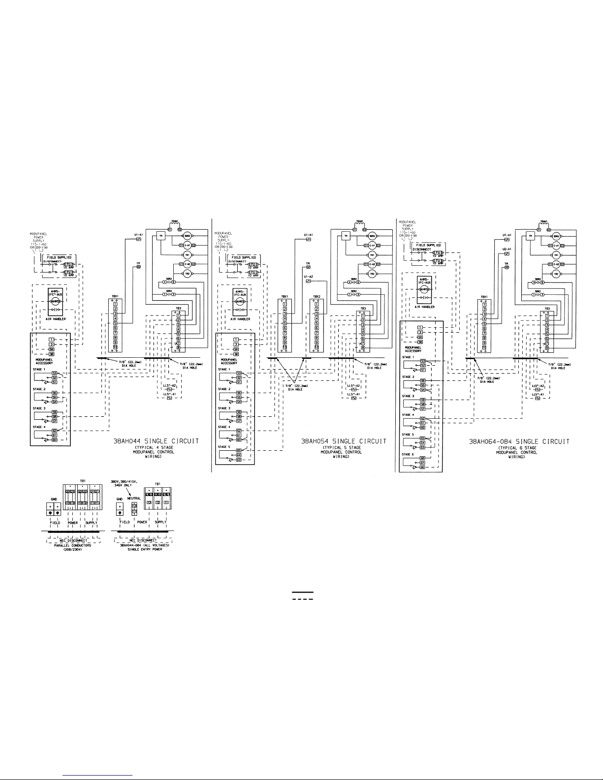
*Field-supplied.
NOTES:
1. Factory wiring is in accordance with NEC; field modifications or additions must be in compliance with all applicable codes.
2. Wiring for field power supply must be rated 75 C minimum. Use copper,copper-clad aluminum, oraluminum conductors. Maximumin coming wire size for each terminal block is 500 kcmil.
3. Terminalblocks TB3,TBX1, and TBX2are for externalfield control connections. Control connections are to be Class 1 wiring.
4. Field-supplied components (IFC, LLS-A1, and LLS-A2) must have a
maximum sealed coil rating of 30 va each (0.25 amp at 120 vac,
13 amp at 230 vac). AHMS IFC-AUX must have minimum pilot duty
rating of 400va each (3.4amps at120 vac, 1.8amps at 230vac) each.
5. Replacement of factory wires must be with type 105 C wire or its
equivalent.
6. Field-supplied liquid linesolenoid valves installedat theevaporator are
required on all units.
7. Control has 175 va of power available for field-installed accessories.
Fig. 25 — Field Wiring, Single ModuPanel™ Control, 38AH044-084 Optional Single-Circuit Units
LEGEND
AHMS — Air Handler Motor
Starter
AUX — Auxiliary
C—Compressor Contactor
FU — Fuse
GND — Equipment Ground
IFC — Indoor Fan Control
kcmil — Thousand Circular Mils
LLS — Liquid Line Solenoid
NEC — National Electrical Code
(U.S.A. Standard)
SDR — Solenoid Drop Relay
TB — Terminal Block
TBX — Terminal Block for
VariableAir Volume
Units
TM — Timer Motor
TR — Timer Relay
TRAN — Transformer
U—Unloader Solenoid
Factory Wiring
Field Wiring
33
Page 34
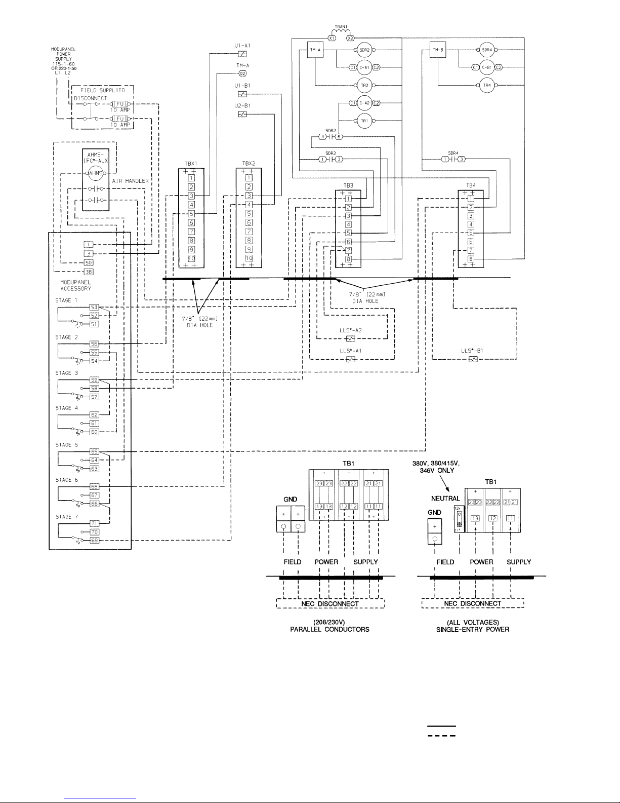
*Field-supplied.
NOTES:
1. Factory wiring is in accordance with NEC. Field modifications
or additions must be in compliance with all applicable codes.
2. Wiring for fieldpower supply mustberated 75 Cminimum.Use
copper,copper-clad aluminum, or aluminum conductors. Maximum incoming wire size for each terminal block is 500 kcmil.
3. Terminal blocks TB3, TB4, TBX1, and TBX2 are for external
field control connections. Control connections are to be
Class 1 wiring.
4. Field-supplied components(IFC,LLS-A1,A2,B1, andB2)must
have a maximum sealed coil rating of 30 va each (0.25 amp at
120 vac, 0.13 amp at 230 vac). AHMS IFC-AUX contact must
have minimum pilot duty rating of 325 va each (2.7 amps at
120 vac, 1.4 amps at 230 vac).
5. Replacement of factory wires must be with type 105 C wire or
its equivalent.
6. Field-supplied liquid linesolenoid valves installedatthe evaporator are required on all units.
7. Control has 25 va of power available for field-installed
accessories.
LEGEND
AHMS — Air Handler Motor Starter
AUX — Auxiliary
C—Compressor Contactor
FU — Fuse
GND — Equipment Ground
IFC — Indoor Fan Control
kcmil — Thousand Circular Mils
LLS — Liquid Line Solenoid
NEC — National Electrical Code
(U.S.A. Standard)
SDR — Solenoid Drop Relay
TB — Terminal Block
TBX — Terminal Block for Variable
Air Volume Units
TM — Timer Motor
TR — Timer Relay
TRAN — Transformer
U—Unloader Solenoid
Factory Wiring
Field Wiring
Fig. 26 — Field Wiring, Single ModuPanel™ Control, Unit 38AH094
34
Page 35
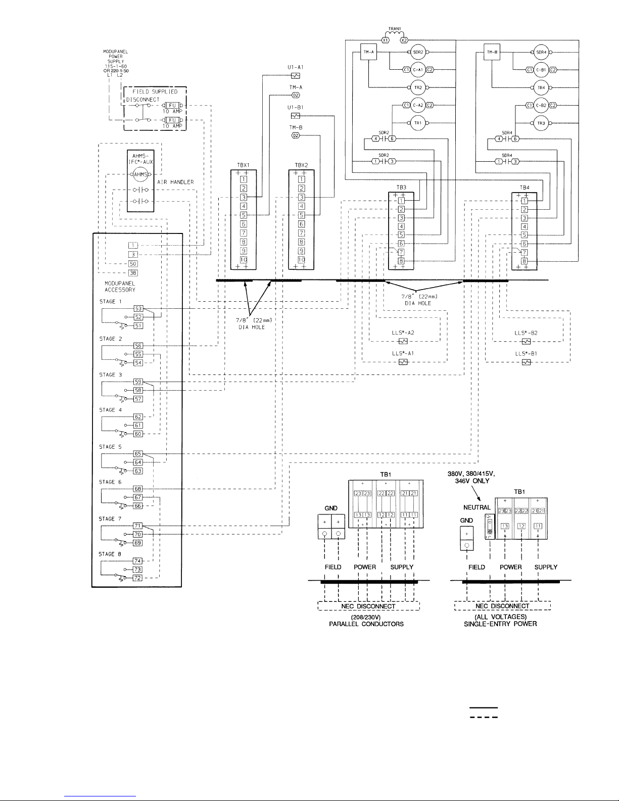
*Field-supplied.
NOTES:
1. Factory wiring is in accordance with NEC. Field modifications or
additions must be in compliance with all applicable codes.
2. Wiring for field power supply must be rated 75 C minimum. Use
copper, copper-clad aluminum, or aluminum conductors. Maximum incoming wire size for each terminal block is 500 kcmil.
3. Terminal blocks TB3, TB4, TBX1, and TBX2 are for external field
control connections. Control connections are to be Class 1 wiring.
4. Field-supplied components (IFC, LLS-A1, A2, B1, and B2) must
have a maximum sealed coil rating of 30 va each (0.25 amp at
120 vac,0.13amp at 230 vac).AHMS IFC-AUX contactmust have
minimum pilot duty rating of 375 va each (3.1 amps at 120 vac,
1.6 amps at 230 vac).
5. Replacement of factory wires must be with type 105 C wire or its
equivalent.
6. Field-supplied liquid line solenoid valves installed at the evaporator are required on all units.
7. Control has35va of poweravailable for field-installedaccessories.
LEGEND
AHMS — Air Handler Motor Starter
AUX — Auxiliary
C—Compressor Contactor
FU — Fuse
GND — Equipment Ground
IFC — Indoor Fan Control
kcmil — Thousand Circular Mils
LLS — Liquid Line Solenoid
NEC — National Electrical Code
(U.S.A. Standard)
SDR — Solenoid Drop Relay
TB — Terminal Block
TBX — Terminal Block for
VariableAir Volume
Units
TM — Timer Motor
TR — Timer Relay
TRAN — Transformer
U—Unloader Solenoid
Factory Wiring
Field Wiring
Fig. 27 — Field Wiring, Single ModuPanel™ Control, Unit 38AH104
35
Page 36
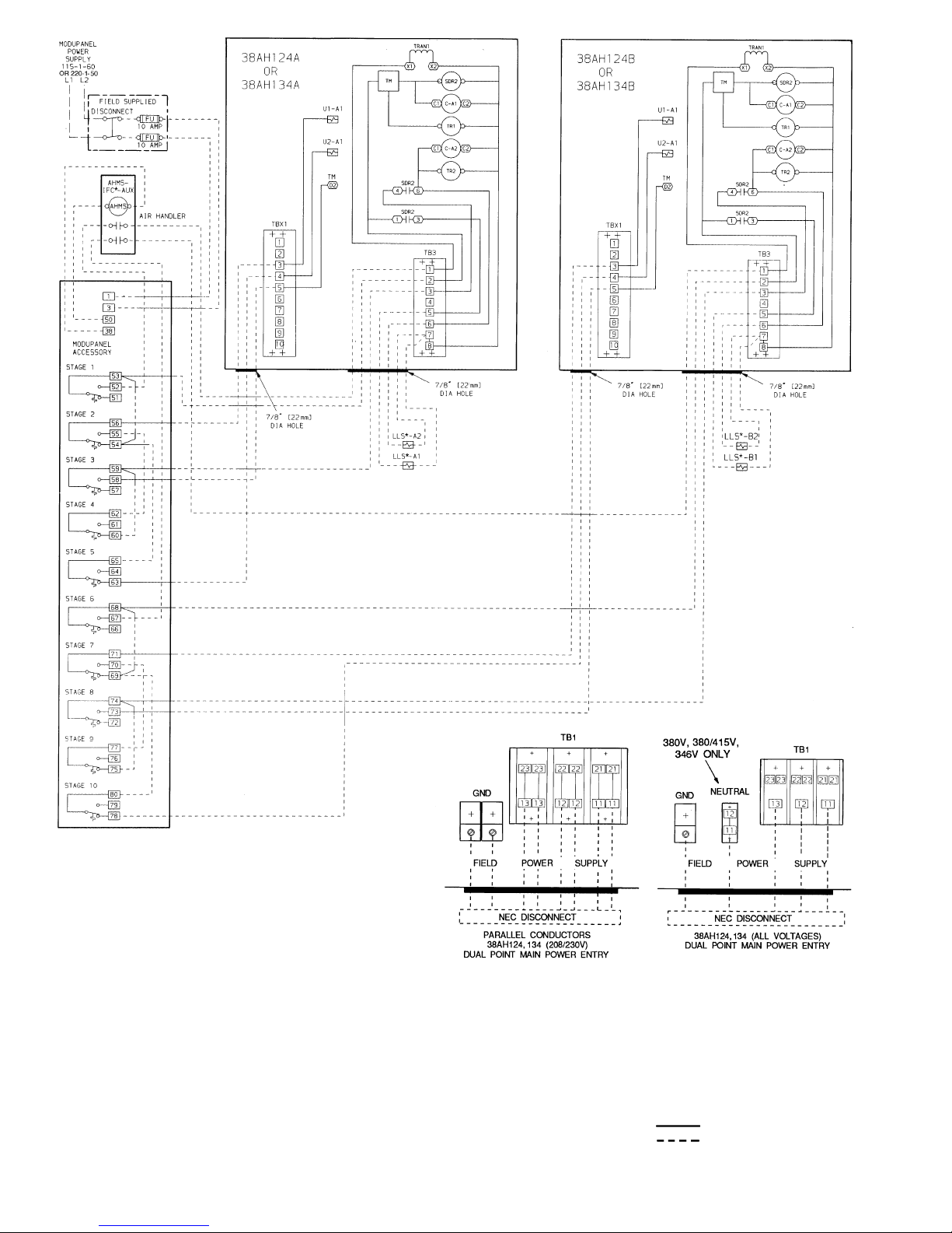
*Field-supplied.
NOTES:
1. Factory wiring is in accordance with NEC. Field modifications or
additions must be in compliance with all applicable codes.
2. Wiring for field power supply must be rated 75 C minimum. Use
copper, copper-clad aluminum, or aluminum conductors. Maximum incoming wire size for each terminal block is 500 kcmil.
3. Terminal blocks TB3 and TBX1 are for external field control connections. Control connections are to be Class 1 wiring.
4. Field-supplied components(IFC, LLS-A1 andA2)musthave amaximum sealed coil rating of 30 va each (0.25 amp at 120 vac,
0.13 amp at 230 vac). AHMS IFC-AUX contact must have minimum pilot duty rating of 400 va each (3.4 amps at 120 vac,
1.8 amps at 230 vac).
5. Replacement of factory wires must be with type 105 C wire or its
equivalent.
6. Field-supplied liquid line solenoid valves installed at the evaporator are required on all units.
7. Units have 175 va of power available for field-installed
accessories.
LEGEND
AHMS — Air Handler Motor Starter
AUX — Auxilliary
C—Compressor Contactor
FU — Fuse
GND — Equipment Ground
IFC — Indoor Fan Control
kcmil — Thousand Circular Mils
LLS — Liquid Line Solenoid
NEC — National Electrical Code
(U.S.A. Standard)
SDR — Solenoid Drop Relay
TB — Terminal Block
TBX — Terminal Block for Variable
Air Volume Units
TM — Timer Motor
TR — Timer Relay
TRAN — Transformer
U—Unloader Solenoid
Factory Wiring
Field Wiring
Fig. 28 — Field Wiring, Single ModuPanel™ Control, Units 38AH124 and 134
36
Page 37
Table 15 — Main Power Connection and Control Circuit Wiring
MAIN POWER CONNECTION CONTROL CIRCUIT
Electrical
Characteristics
(V-Ph-Hz)
Qty
Terminal
Blocks
Qty
Parallel
Conductors*
Max Wire
Size
(kcmil)
Control Power
(V)
Safety Circuit
(V)
208/230-3-60 1 6 500 115† 24
460-3-60
575-3-60
1 3 500 115† 24
230-3-50 1 6 500 230 24
380-3-60
380/415-3-50
1 3 500 230 24
346-3-50 1 3 500 200 24
LEGEND
kcmil — Thousand Circular Mils
*Conductors are from the safety disconnect.
†Control power is accomplished with a step-down transformer where primary voltage is field voltage.
Step 5 — Install Accessories
LOW-AMBIENT OPERATION
Units 38AH044-084, 124, and 134 — If operating tempera-
tures below 55 F (13 C) are expected, Motormastert III fan
motor control is recommended. Refer to separate installation instructions for low-ambient operation guidelines.
Units 38AH094 and 104 — If operating temperatures below
45 F (7 C) are expected, Motormaster III fan motor control
is recommended. Refer to separate installation instructions
for low-ambient operation guidelines.
MISCELLANEOUS ACCESSORIES — For applications
requiring special accessories, the following packages are
available: condenser coil hail guard package, gage panel,
unloader package, unloader conversion kits, sound reduction package, condenser coil protective grilles, compressor
security grilles, ModuPanel™ control, and thermostat transformer relay package.
PRE-START-UP
IMPORTANT:Beforebeginning Pre-Start-Up or StartUp, review Start-Up Checklist at the back of this publication. The Checklist assures proper start-up of aunit
and provides a record of unit condition, application requirements, system information, and operation at initial start-up.
Do not attempt to start the air-conditioning system until
following checks have been completed.
System Check
1. Check all system components, including the airhandling equipment. Consult manufacturer’s instructions. If the unit has field-installed accessories, be sure
all are properly installed and wired correctly. Refer to
unit wiring diagrams.
2. Backseat (open) compressor suction and discharge shutoffvalves.Closevalvesoneturntoallowrefrigerantpressure to reach the test gages.
3. Open liquid line service valves.
4. Check tightness of all electrical connections.
5. Oil should be visible in the compressor sight glasses.
See Fig. 29. An acceptable oil level in the compressor
is from
1
⁄8to1⁄3of sight glass. Adjust the oil level as
required. No oil should be removed unless the crankcase heater has been energized for at least 24 hours. See
Preliminary Oil Charge section on page 38, for Carrierapproved oils.
6. Electrical power source must agree with unit
nameplate.
Crankcase heaters on all units are wired into the
control circuit, so theyare always operable as long
as the main power supply disconnect is on (closed),
even if any safety device is open. Compressor heaters must be on for 24 hours prior to the start-up of
any compressor.
7. Crankcase heaters must be firmly locked into compres-
sors, and must be on for 24 hours prior to start-up.
8. Fan motors are 3-phase. Check rotation of fans during
first start-up check. Fan rotation is clockwise as viewed
from top of unit. If fan is not turning clockwise, reverse
2 of the power wires.
9. Check compressor suspension. On units 38AH044-084,
124, and 134, snubber washers (for noise suppression)
can be moved with finger pressure. On units 38AH094
and 104, rails allow compressors to float freely on compressor rail springs.
10. On 38AH074,084 single-circuit units and Module
38AH134B, ensure that the packaging block located between the oil equalization tube and the compressor crossbrace has been removed.
37
Page 38
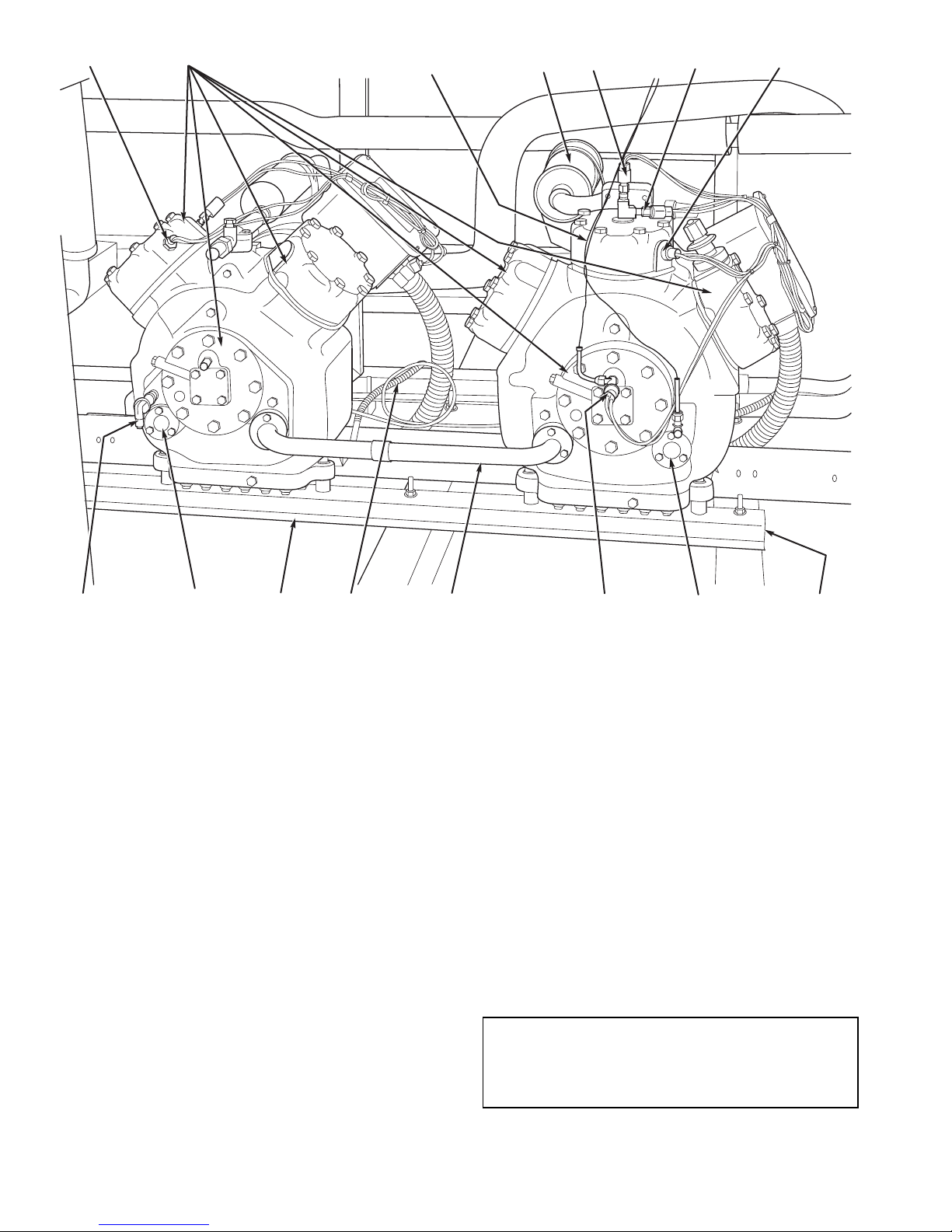
START-UP
Compressor crankcase heaters must be on for 24 hours
before start-up. To energize the crankcase heaters, set the
space thermostat above the ambient so there will be no demand for cooling. Close the field disconnect and turn on the
fan circuit breakers. Leave the compressor circuit breakers
off/open. The crankcase heaters are now energized.
Preliminary Checks
1. Ensure that compressor service valves are backseated.
2. Verify that each compressor on units 38AH044-084, 124,
and 134 floats freely on its mounting springs. Verify that
each compressor on units 38AH094 and 104 floats freely
on its rails.
3. Check that electric power supply agrees with unit name-
plate data.
4. Verify that compressor crankcase heaters are securely in
place.
5. Check that compressor crankcase heaters have been on at
least 24 hours.
6. Note that compressor oil level is visible in the sight glass.
7. Recheck for leaks using same procedure as previously out-
lined in Step 3 — Make Refrigerant Piping Connections,
page 14.
8. If any leaks are detected, evacuate and dehydrate as previously outlined in Step 3 — Make Refrigerant Piping
Connections, page 14.
Preliminary Oil Charge — Each compressor is fac-
tory charged with oil (see Table 3A, 3B, 4A, or 4B). When
oil is checked at start-up, it may be necessary to add or remove oil to bring it to the proper level. One recommended
oil level adjustment method is as follows:
ADD OIL — Close suction shutoff valve and pump down
crankcase to 2 psig (14 kPa). (Low-pressure cutout must be
jumped.) Wait a few minutes and repeat until pressure remains steady at 2 psig (14 kPa). Remove oil fill plug above
the oil level sight glass, add oil through plug hole, and replace plug. Run compressor for 20 minutes and check oil
level.
IMPORTANT: For units with 2 compressors per refrigeration circuit, both compressors must be running
to adjust the oil level. Two oil level equalizer lines
between compressors distribute the oil to each
compressor.
DISCHARGE
GAS THERMOSTAT
CYLINDER
HEADS
OIL PRESSURE SWITCH AND
CAPACITY CONTROL
PRESSURE SWITCH CAPILLARIES
MUFFLER
HIGHPRESSURE
SWITCH
FAN CYCLING
PRESSURE SWITCH
DISCHARGE GAS
THERMOSTAT
MOUNTING
SPRING
(HIDDEN)
SIGHT
GLASS
LOWPRESSURE
SWITCH
OIL
EQUALIZER
LINE
CRANKCASE
HEATER
RAIL
SIGHT
GLASS
PRESSURE RELIEF
VALVE
NOTE: Units 38AH044-084and38AH124,134 compressors are pan
mounted. Units38AH094 and 104 compressorsare mounted on rails.
Fig. 29 — 06E Compressors, Typical
38
Page 39
NOTE: Use only Carrier approved compressor oil. Approved sources are: Petroleum Specialties Inc. (Cryol 150A),
Texaco, Inc. (CapellaWF-32-150), and Witco Chemical Co.
(Suniso 3GS). Do not reuse oil that has been drained out, or
oil that has been exposed to atmosphere.
REMOVE OIL — Pump down compressor to 2 psig
(14 kPag). Loosen the1⁄4-in. (6.4-mm) pipe plug at the compressor base and allow the oil to seep out past the threads of
the plug.
NOTE: The crankcase will be slightly pressurized. Do not
remove the plug, or the entire oil charge will be lost.
Small amounts of oil can be removed throughtheoil pump
discharge connection while the compressor is running.
PreliminaryCharge— RefertoGTAC II (General Train-
ing Air Conditioning), Module 5, Charging, Recovery,
Recycling, and Reclamation for charging procedures. Using
the liquid charging method and charging by weight procedure, charge each circuit with the amount of R-22 listed in
Table 3A, 3B, 4A, or 4B.
Never charge liquid into the low-pressure side of system. Do not overcharge. During charging or removal of
refrigerant, be sure indoor-fan system is operating.
Start Unit — The field disconnect is closed, the fan cir-
cuit breaker is closed, and the space thermostats are setabove
ambient so that there is no demand for cooling. Only the
crankcase heaters are energized.
Close the compressor circuit breakers and then reset both
space thermostats below ambient so that a call for stage one
cooling is ensured. Lead refrigeration circuit ther-
mostat TC1 must be set to call for cooling at a lower temperature than lag refrigeration circuit thermostat TC2.
See Table 16 for lead/lag circuits on all units. Now set TC2
for cooling.
NOTE: Do not use circuit breakers to start and stop the compressor except in an emergency.
38AH044-084 DUAL-CIRCUIT UNITS — Start-up of lead
compressor A1 (Table 16) will be delayed from 12 seconds
to 5
1
⁄2minutes from the time the call for cooling is initiated
by TC1.Afterthe lead compressor starts, close the TC2 thermostat to start lag circuit compressor B1. Compressor B1
will start a minimum of 60 seconds after thermostat TC2 is
closed.
38AH044-084 OPTIONAL SINGLE CIRCUIT UNITS —
Start-up of lead compressor A1 (Table 16) is delayed from
12 seconds to 5
1
⁄2minutes from the time the call for cooling
is initiated by TC1. Closure of TC2 will actuate LLS-A2.
Lag compressorA2 is controlled by D-D2 timer contacts and
capacity control pressure switches (CCPSs) which monitor
compressor suction pressure. The lag compressor starts approximately 21⁄2minutes after the lead compressor starts if
the suction pressure is above the CCPS set point.
38AH094,104 UNITS — Start-up of lead circuit A,
compressor A1 (Table 16) is delayed from 12 seconds to
51⁄2minutes from the time the call for cooling is initiated.
After lead circuit A, compressor A1 starts, close refrigeration circuit thermostat TC2 to start lag circuit B, lead
compressor B1. Start-up of compressor B1 is delayed from
12 seconds to 5
1
⁄2minutes. (Circuit B of unit 38AH094 has
only one compressor.)
Each circuit’s lead compressor start-up is controlled by
the unit control timer. The circuit’s lag compressor start-up
is controlled by the D-D2 timer contacts and capacity
control pressure switches (CCPSs) which monitor compressor suction pressure. The circuit’s lag compressor will start
approximately 2
1
⁄2minutes after a call for cooling if com-
pressor pressure is above CCPS set point.
38AH124,134 UNITS — Start-up of the lead circuit
(Module 124A or 134A) lead compressor A1 (Table 16) is
delayed from 12 seconds to 51⁄2minutes from the time the
call for cooling is initiated by TC1. Lag compressor A2 is
controlled by D-D2 timer contacts and capacitycontrol pressure switches (CCPSs) which monitor compressor suction
pressure. The lag compressor starts approximately 21⁄2minutes after the lead compressor starts if the suction pressure
is above the CCPS set point.
After the lead circuit (Module 124A or 134A) lead compressorA1(Table 16) starts,closetheTC2 thermostat to start
the lag circuit (Module 124B or 134B) lead compressor(A1).
Lag circuit compressor A1 start-up is delayed from 12 seconds to 5
1
⁄2minutes from the time the call for cooling is
initiated by TC2. Lag compressor A2 is controlled by D-D2
timer contacts and CCPSs which monitor compressor suction pressure. Lag compressor A2 starts approximately 21⁄
2
minutes after lead compressor A1 starts if the suction pressure is above the CCPS set point.
Adjust Refrigerant Charge
Never charge liquid into the low-pressure side of system. Do not overcharge. During charging or removal of
refrigerant, be sure indoor-fan system is operating.
With all fans operating, and all compressors on the cir-
cuit being serviced operating at full capacity, adjust the
refrigerant charge in accordance with the unit charging charts
located on the inside of the control box doors and in
Fig. 30-43. Charge vapor into compressor low-side service
port located above oil pump crankshaft housing. Measure
pressure at the liquid lineservicevalve,makingsureaSchrader
depressor is used if required. Also, measure liquid line temperature as close to the liquid service valve as possible.Add
charge until the pressure and temperature conditions of the
charging chart curve are met. If liquid pressure and temperature point fall above curve, add charge. If liquid pressure
and temperature point fall below curve, reduce the charge
until the conditions match the curve.
If the sight glass at location A (Fig. 11 and 12) is cloudy,
check refrigerant charge again. Ensure all fans and com-
pressors on the circuit being serviced are operating. Also
ensure maximum allowable liquid lift has not been
exceeded.
If the sight glass at location A is clear and the sight
glass at location B is cloudy, a restriction exists in the
line between the 2 sight glasses. Check for a plugged filter
drier or partially open solenoid valve. Replace or repair, as
needed.
39
Page 40
Table 16 — Index of Lead/Lag Circuits and Compressors
UNIT
38AH
044-084
STD
044-084
OPT
094 104 124 134
LEAD CIRCUIT AAAA
Module
124A
Module
134A
Compressor, Lead A1 A1 A1 A1 A1 A1
Compressor; Lag *A2A2A2A2A2
LAG CIRCUIT B†BB
Module
124B
Module
134B
Compressor, Lead B1 B1 B1 A1 A1
Compressor; Lag * * B2 A2 A2
LEGEND
OPT — Optional Single-Circuit Units
STD — Standard Dual-Circuit Units
*Circuit has only one compressor.
†Units have only one circuit.
Check Compressor Oil Level— After adjusting the
refrigerant charge, allow each circuit to run fully loaded for
20 minutes. Running oil level should be1⁄8to1⁄3up on the
sight glass. Stop the compressors at the field power supply
disconnect and check the crankcase oil level. Add oil only if
necessary to bring the oil into view in the sight glass. If oil
is added, run the circuit for an additional 10 minutes, then
stop and check oil level. If the level remains low, check the
piping system for proper design for oil return; also, check
the system for leaks.
If the initial check shows too much oil (too high in the
sight glass) remove oil to proper level. See Preliminary Oil
Charge for proper procedure for adding and removing oil.
When the above checks are complete, repeat the procedure with the unit operating at minimum load conditions.
UNITS 38AH044-084,124, AND 134 — For this minimum
load check, run the lead compressor ofeach refrigeration circuit fully unloaded with the lag compressor not operating.
Unload the compressor(s) by turning the control set point
adjustment nut counterclockwise until the adjustment nut
stops. The unloader is now at 0 psig (0 kPag) set point. If
electrically actuated unloaders are installed, energizethe solenoid to unload the compressor. Recheck the compressor
oil level as described inCheck Compressor Oil Level above.
Return unloader to original setting after checks are
complete.
UNITS 38AH094,104 — For this minimum load check, the
lead compressor (A1, B1) of each refrigeration circuit is unloaded. See T able16.The lag compressor(A2,B2 [38AH104
only]) of each refrigeration circuit must not be operating.
Unload the compressor(s) by turning the control set point
adjustment nut counterclockwise untiltheadjustmentnutstops.
The unloader is now at 0 psig (0 kPag) set point. If electrically actuated unloaders are installed, energize the solenoid
to unload the compressor.
Return unloader to original setting after checks are
complete.
Final Checks — Ensure all safety controls are operat-
ing, control panel covers are on, and the service panels are
in place.
40
Page 41
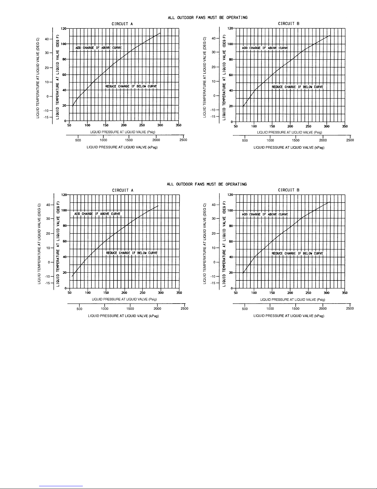
Fig. 30 — Charging Chart — Unit 38AH044; 50/60 Hz — Dual Circuit
Fig. 31 — Charging Chart — Unit 38AH054; 50/60 Hz — Dual Circuit
41
Page 42
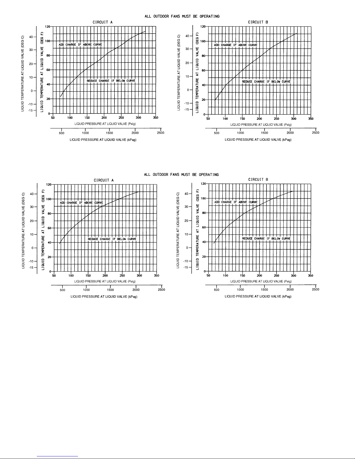
Fig. 32 — Charging Chart — Unit 38AH064; 50/60 Hz — Dual Circuit
Fig. 33 — Charging Chart — Unit 38AH074; 50/60 Hz — Dual Circuit
42
Page 43
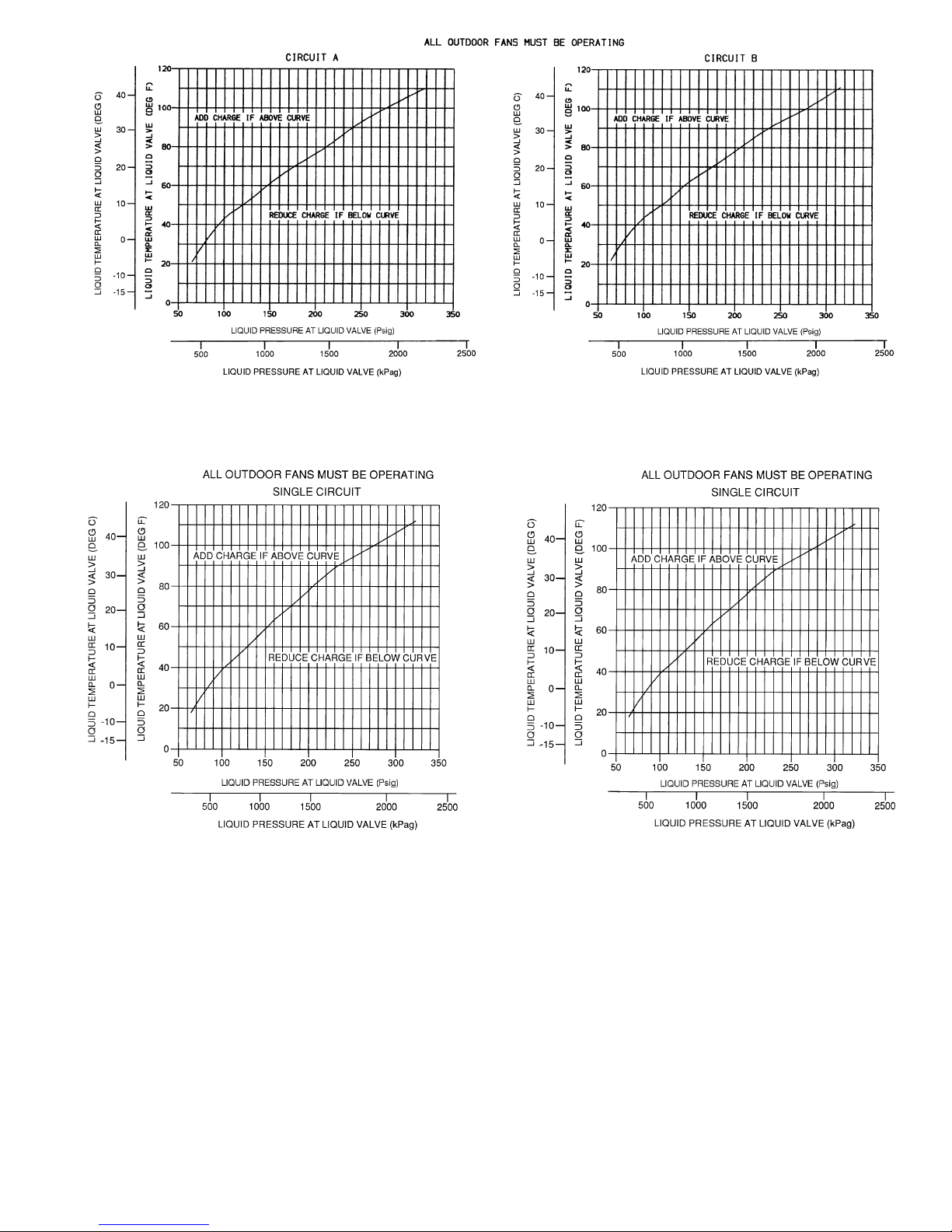
Fig. 34 — Charging Chart — Unit 38AH084; 50/60 Hz — Dual Circuit
Fig. 35 — Charging Chart — Unit 38AH044;
50/60 Hz — Optional Single Circuit
Fig. 36 — Charging Chart — Unit 38AH054;
50/60 Hz — Optional Single Circuit
43
Page 44
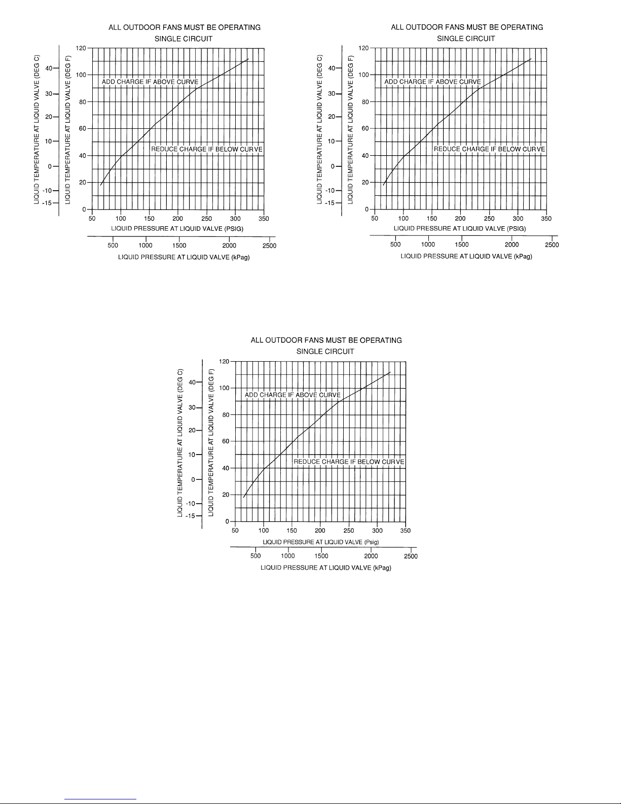
Fig. 37 — Charging Chart — Unit 38AH064;
50/60 Hz — Optional Single Circuit
Fig. 38 — Charging Chart — Unit 38AH074;
50/60 Hz — Optional Single Circuit
Fig. 39 — Charging Chart — Unit 38AH084;
50/60 Hz — Optional Single Circuit
44
Page 45
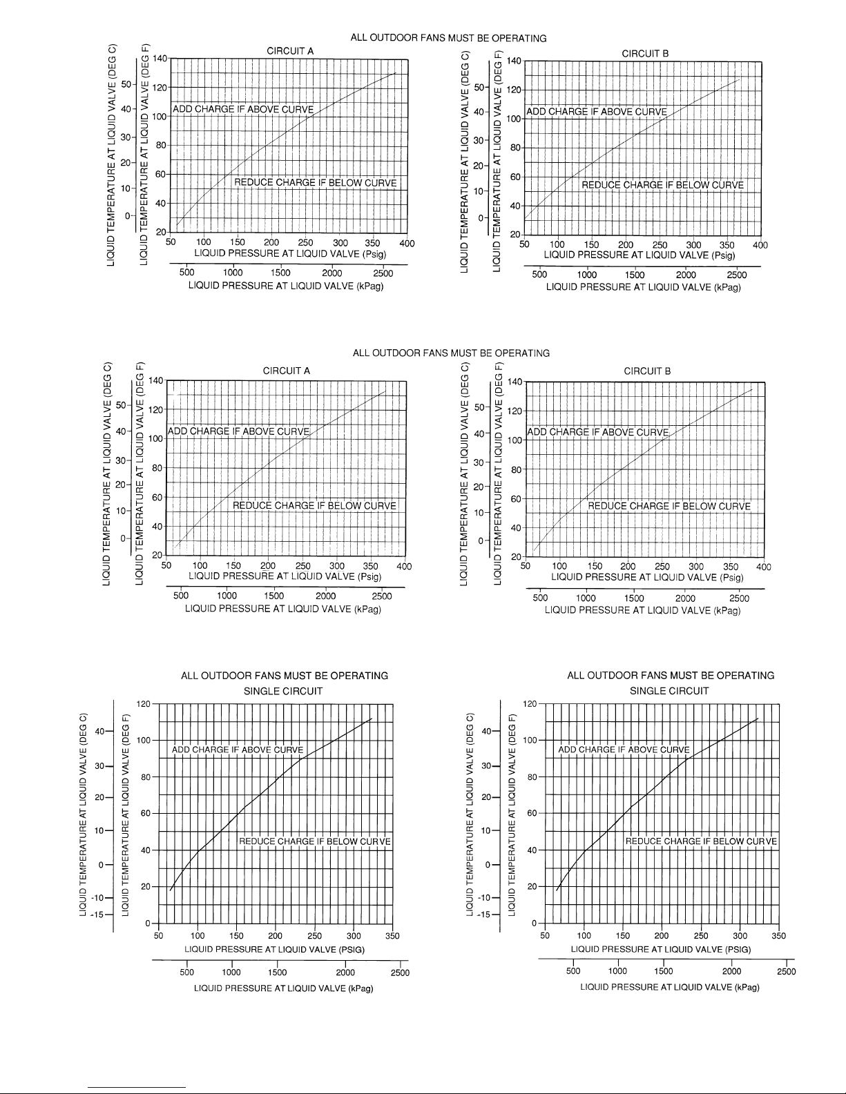
Fig. 40 — Charging Chart — Unit 38AH094; 50/60 Hz
Fig. 41 — Charging Chart — Unit 38AH104; 50/60 Hz
Fig. 42 — Charging Chart — Modules 124A, 124B,
and 134A; 50/60 Hz
Fig. 43 — Charging Chart — Module 134B;
50/60 Hz
45
Page 46
SERVICE
ELECTRIC SHOCK HAZARD
Turn off all power to unit before servicing.
The ON-OFF switch on control panel
does not shut off control power; use field
disconnect.
CoilCleaning — Clean the coils with a vacuum cleaner,
compressed air, water, or a non-wire bristle brush.
Refrigerant Circuit
LEAK TESTING — Units are shipped with a holding charge
of R-22 (see Table 3A, 3B, 4A, or 4B) and should be under
sufficient pressure to conduct a leak test. If there is no pressure in the system, introduce enough nitrogen to search
for the leak. Repair the leak using good refrigeration practices.Afterleaks are repaired, system must be evacuated and
dehydrated using methods described inGTAC II ,Module 4,
System Dehydration.
REFRIGERANT CHARGE (Refer to Table 3A, 3B, 4A, or
4B) —At the liquid line connection point on each circuit is
a factory-installed liquid line service valve. On each
valve is a1⁄4-in. Schrader connection for charging liquid
refrigerant.
Charging with Unit Off and Evacuated — Close liquid
line service valve before charging. Weigh in charge shown
in Table 3A, 3B, 4A, or 4B. Open liquid line service valve;
start unit and allow it to run several minutes fully loaded.
Check for a clear sight glass. Be sure clear condition is liquid and not vapor. Complete charging the unit in accordance
with Start-Up, Adjust Refrigerant Charge, page 39.
Charging with Unit Running —Ifchargeistobeaddedwhile
unit is operating, it is necessary to have all condenser fans
and compressors operating. It may be necessary to block condenser coils at low-ambient temperatures to raise condensing pressure to approximately 280 psig (1931 kPag) to turn
all condenser fans on. Do not totally block a coil to do this.
Partially block all coils in uniform pattern. Charge
vapor into compressor low-side service port located above
oil pump crankshaft housing. Charge each circuit until sight
glass shows clear liquid.
Troubleshooting— Refer toTroubleshooting chart lo-
cated at back of book.
Oil Pressure Safety Switch (OPS) — An oil pres-
sure safety switch for each of the independent refrigerant
circuits shuts off the compressor in thatcircuit if oil pressure
is not established at start-up or maintained during operation.
If the OPS stops the unit, determine and correct the cause
before restarting the unit. Failure to do so constitutes equip-
ment abuse and could affect the warranty.
Compressor Motor Protection
CIRCUIT BREAKER —Amanual reset, calibrated trip circuit breaker for each compressor protects against overcurrent. Do not bypass connections or increase size of circuit
breakerforany reason.Iftrouble occurs, determine the cause
and correct it before resetting the breaker.
DISCHARGE GAS THERMOSTAT — A sensor in the
cylinder head of each compressor (Fig. 29) shuts down the
compressor if excessively high discharge gas temperature is
sensed. If the discharge gas thermostat shuts the unit down,
it may be reset by the thermostat orpower disconnect switch.
CRANKCASE HEATER (See Fig. 29) — Each compressor
has an electric crankcase heater located in the bottom cover.
The heater is held in place by a clip and bracket and must be
tightly connected since exposure to the air causes the heater
to burn out. Each heater is wired into the compressor control
circuit through a relay which energizes only when the compressor is off. The heater keeps the oil at a temperature that
prevents excessive absorption of refrigerant during shutdown periods.
Energize the crankcase heaters when the unit is not running except during prolonged shutdown or servicing. Ener-
gize the heaters at least 24 hours before restarting the unit
after prolonged shutdown.
TIME GUARDt FUNCTION —Thisfunctionpreventscompressors from short-cycling.
Fan Motor Protection — Fan motors are protected
by a single circuit breaker for all motors.
Head Pressure Control— Head pressure control re-
duces condenser capacity under low-ambient conditions. This
is achieved by fan cycling control (standard, all units) and
Motormastert III control accessory (field installed).
FAN CYCLING —All condensing units have standard provision for fully automatic intermediate season head pressure
control through fan cycling (see Table 17).
38AH044-084 Dual-Circuit Units — Fans no. 3 and 4 are
cycled by pressure control on all units. On 38AH074 and
084, fans no. 5 and 6 are also cycled by pressure control.
38AH044-084 Optional Single Circuit Units — Fans no. 3
and 4 are cycled by pressure control on all units. On 38AH074
and 084, fans no. 5 and 6 are cycled by an air-temperature
switch located in the bottom shelf of the control box.
Units 38AH094,104 — Fans no. 3 through 6 are cycled by
pressure control.
Units 38AH124,134 — Fans no. 3 and 4 on each unit module are cycled by pressure control. On module 134B only,
fans no. 5 and 6 are cycled by an air-temperature switch located in the bottom shelf of the control box.
Pressure control is achievedviaafancyclingpressureswitch
located on the cylinder head of the unit or circuit lead compressor (see Fig. 29).
The air-temperature switch used to control fans no. 5 and
6 on 38AH074,084 optional single-circuitunits and on module 134B is closed and cycles the fans on when the ambientair temperature is above 70 F (21 C).
Table 17 — Fan Cycling Control — Psig (kPag)
Control by Pressure* ±10 (69)
Switch Opens 160 (1103)
Switch Closes 255 (1758)
*On all units, fans no. 3 and 4; also on unit 38AH074, 084 (dual-
circuit units only) and 38AH094,104, fans no. 5 and 6.
NOTE: Fansno.1 and 2 arenoncycling.Units 38AH074,084 optional
single-circuit units and module 134B fans no. 5 and 6 are
cycled by an air-temperature switch which operates above 70 F
(21 C) ambient-air temperature.
38AH044-064,
Modules 124A, 124B,
134A
38AH074-104,
Module 134B
46
Page 47
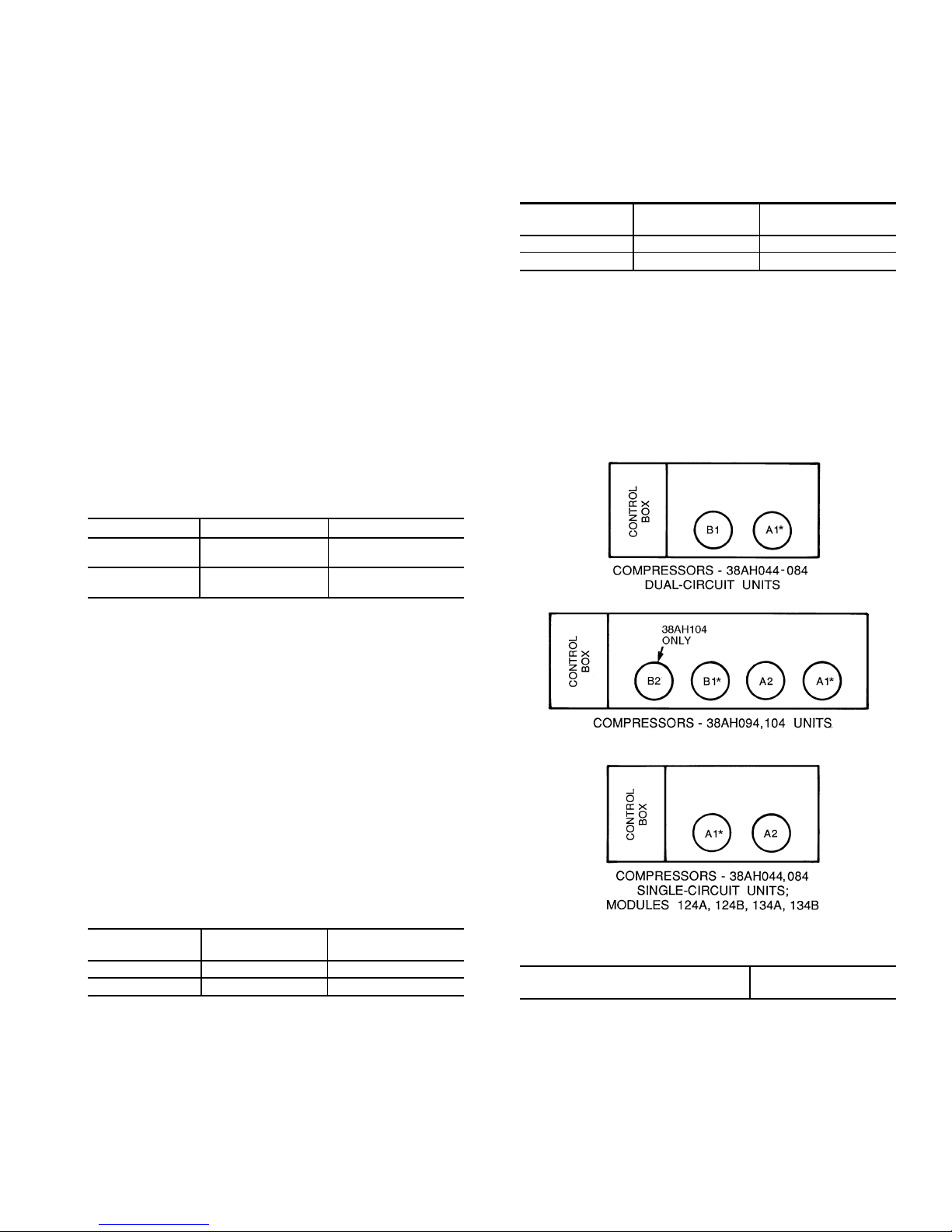
WinterStartControl— A2
1
⁄2-minute low-pressure switch
(LPS) bypass function in the timer prevents nuisance LPS
trips during start-up in low-ambient conditions.
High-Pressure Switch — This switch has nonadjust-
able settings. Figure 29 shows connection on acylinderhead.
See Table 18 for pressure switch settings.
NOTE: High-pressure switch must be removed from cylinder head before removing compressor from the unit.
TO CHECK — Slowly close the discharge shutoff valve until the compressor shuts down. This should be at approximately 426 psig (2935 kPag). Slowly open the valve. When
the pressure drops to approximately 320 psig (2205 kPag),
the pressure switch resets. To reenergize the control circuit,
manually switch the fan circuit breaker off and then on. The
compressor starts again under Time Guardt controls.
Low-PressureSwitch— Thelow-pressureswitch(LPS)
has fixed nonadjustable settings. It is located at the pump
end of the compressor above the bearing head. See Table 18
for pressure switch settings.
TO CHECK — Slowly close the suction cut-off valve and
allow the compressor to shut down. This should occur at
approximately 27 psig (186 kPag). Slowly open the valve.
The compressor restarts under Time Guard control when the
pressure builds to approximately 67 psig (462 kPag).
Table 18 — Pressure Switch Settings,
Psig (kPag)
SWITCH CUTOUT CUT-IN
High
426 ± 7 320 ± 20
(2935 ± 48) (2205 ± 138)
Low
27 ± 4 67 ± 7
(186 ± 28) (462 ± 48)
Capacity Control
38AH044-084 DUAL-CIRCUIT UNITS — Capacity control is achieved by a pressure-actuated cylinder bank unloader on lead compressor A1.As the cooling load decreases
and the suction pressure drops, the unloader actuates at the
pre-set suction pressure and unloads the cylinder bank. (See
Fig. 44 and Table 19A.) The unloading of the compressor
cylinder bank has no effect on the operation of lag compressor B2, which is controlled by TC2.
38AH044-084 SINGLE-CIRCUIT UNITS AND MODULES 124A, 124B, 134A, AND 134B — Capacity control
is achieved by a pressure-actuated cylinder bank unloader
on lead compressor A1. See Table 16. As the cooling load
decreases and the suction pressure drops, the unloader
actuates at the pre-set suction pressure and unloads the cylinder bank. (See Fig. 44 and Table 19B and 20.) Lag compressorA2 is controlled by fixed settingcapacitycontrolpressure
switches (CCPSs) as follows:
CUT-IN —
Psi (kPa)
CUTOUT —
Psi (kPa)
CCPS 1 83 (572) 63 (531)
CCPS 2 80 (551) 53 (365)
CCPS — Capacity Control Pressure Switch
If suction pressure continues to drop after lead compressor A1 unloads and lag compressor A2 is operating, A2 will
stop operating when the suction pressure drops to the CCPS
cutout point.
38AH094,104 — Capacity control is achieved bya pressureactuated cylinder bank unloader on the lead compressor
(A1, B1) on each of the 2 refrigeration circuits.As the cooling load decreases and the suction pressure drops, the unloader actuates at the pre-set suction pressure and unloads
the cylinder bank. (See Fig.44 and Table 20.) The unloading
of the compressor cylinder bank has no effect on the operation of the circuit lag compressor (A2,B2 [except 38AH094,
circuit B]) which is controlled by fixed setting capacity control pressure switches (CCPSs) as follows:
CUT-IN —
Psi (kPa)
CUTOUT —
Psi (kPa)
CCPS 1 83 (572) 63 (531)
CCPS 2 80 (551) 53 (365)
CCPS — Capacity Control Pressure Switch
Pressure Relief — High-side pressure relief is pro-
vided by a fusible plug in the liquid line at the service valve.
For low-side pressure relief, a fusible plug is inserted in the
side of the accumulator (all units except38AH044-084 dualcircuit, constant-volume units). See Fig. 45. The 38AH044084 dual-circuit, constant-volume units have a fusible plug
in the suction tubing. A pressure relief valve installed on the
compressor relieves at 450 psig (3102 kPag) (see Fig. 1-6).
Unloader Settings
Unload, psig (kPag) 56 (386)
Load, psig (kPag) 76 (524)
*Unloader location.
Fig. 44 — Unloader Location and Settings
47
Page 48
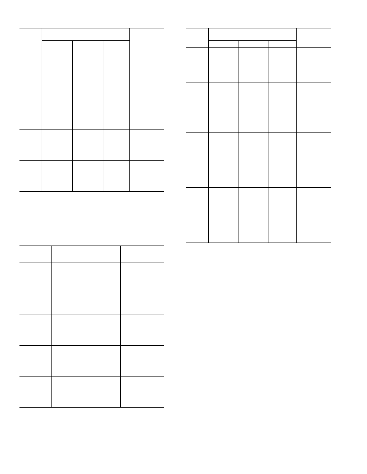
Table 19A — One 2-Stage Thermostat Capacity
Control for 38AH044-084 Dual-Circuit Units
UNIT
38AH
QUANTITY OF LOADED
COMPRESSOR CYLINDERS
SYSTEM
CAPACITY
(%)
Circuit
A
Circuit
B
Total
044
4 4 8 100
24675
40450
20225
054
4 6 10 100
26879
2 4 6* 59
40442
20221
064
6 6 12 100
4 6 10 84
2 6 8* 68
60648
40432
2 0 2* 16
074
6 6 12 100
4 6 10 86
2 6 8* 72
60643
40429
2 0 2* 15
084
6 6 12 100
4 6 10 83
2 6 8* 66
60650
40433
2 0 2* 17
*Requires units with VAV (variable air volume) factory-supplied
option.
NOTE:Unitshave 2 independentrefrigerationcircuits. CircuitA islead
circuit.
Table 19B — One 2-Stage Thermostat Capacity
Controlfor38AH044-084OptionalSingle-CircuitUnits
UNIT
38AH
QUANTITY OF
LOADED CYLINDERS
SYSTEM
CAPACITY
(%)
044
8 100
675
450
225
054
10 100
881
660
656
437
2* 19*
064
12 100
10 82
864
656
436
2† 18
074
12 100
10 81
862
657
438
2† 19
084
12 100
10 83
866
650
433
2† 17
*Requires accessory unloader on lead 06E-265 compressor (A1).
†Requires VAV (variable air volume) factory-installed option or ac-
cessory unloader.
Table 20 — One 2-Stage Thermostat Capacity
Control for 38AH094-134 Units
UNIT
38AH
QUANTITY OF LOADED
COMPRESSOR CYLINDERS
SYSTEM
CAPACITY
(%)
Ckt A Ckt B Total
10 6 16 100
10 4 14 85
10 2 12 70*
10 0 10 55
094 80844
60633
40422
104
10 12 22 100
81220 91
81018 82
10 6 16 73
6 6 12 55
6 4 10 45
06627
40418
04418
2† 0 2 9†
124
12 12 24 100
10 12 22 92
10 10 20 83
8* 10 18 75*
61016 67
6 8* 14 58*
6 6 12 50
4 6 10 42
60625
40417
2* 0 2 8*
134
12 12 24 100
10 12 22 92
10 10 20 83
8* 10 18 75*
61016 67
6 8* 14 58*
6 6 12 50
4 6 10 42
60625
40417
2* 0 2 8*
*RequiresVAV(variableair volume) unitoraccessory unloader(s)field
installed oncircuit lead compressor.Lead compressor is identifiedin
Table 16, page 40.
†Requires field-installedaccessory unloader on circuitleadcompres-
sor. Lead compressor is identified in Table 16, page 40.
NOTES:
1. Temperatures calculated with the minimum number of fans operating per circuit.
2. See Table 16, page 40, for information on lead and lag circuits.
CONTROL SET POINT — Control set point (cylinder load
point) is adjustable from 0 to 85 psig (0 to 586 kPag).
To adjust the set point, turn the control set point adjustment nut clockwise to bottom stop. (See Fig. 46.) In this
position, load-up set point is 85 psig (586 kPag). Turn
adjustment counterclockwise to desired control set point.
Every full turn clockwise decreases the load-up set point by
7.5 psig (52 kPag).
PRESSURE DIFFERENTIAL — Pressure differential
(difference between cylinder load and unload points) is
adjustable from 6 to 22 psig (41 to 152 kPag). To adjust,
turn pressure differential adjustment screw counterclockwise to back stop position. The differential pressure is now
adjusted to 6 psig (41 kPag). Turntheadjustmentscrewclockwise to adjust the differential pressure. Every full clockwise
turn increases the differential by 1.5 psig (10 kPag).
48
Page 49
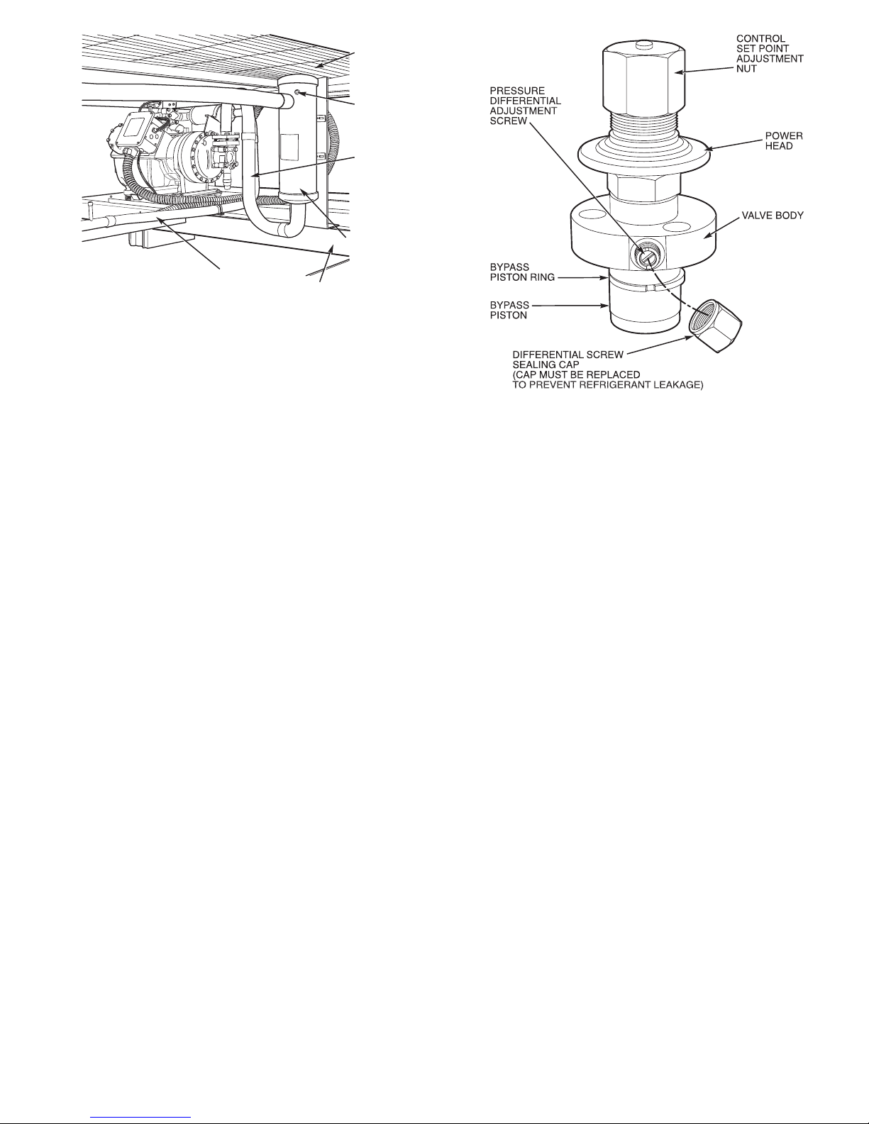
Timer Functions — (See Timer Cycle, Fig. 47.) Each
refrigeration circuit is controlled by an independent timer
which allows for the independent operation of each refrigeration circuit.
NOTE: Unit 38AH044-084 optional single-circuit units have
one timer which controls the lead compressor. Lag compressor is controlled by CCPS (capacity controlpressure switch).
SWITCHA— The timer is energized through contacts A-A1
or A-A2. This establishes the Time Guardt function which
prevents compressor short-cycling. Start of compressor is
delayed approximately 5.5 minutes after shutdown.
SWITCH B — The compressor is initially energized through
contacts B-B1.
SWITCH D — Contacts D-D1 provide a 2
1
⁄2-minute bypass
of the low-pressure switch at start-up for winter-start control. On 38AH044-084 optional single-circuit units, contacts
D-D2 control start-up of compressor A2.
SWITCH E — Contacts E-E1 provide a 40-second bypass
of the oil pressure switch at start-up. If oil pressure does not
build to the required minimum pressure in 40 seconds, the
compressor shuts down and the control circuit locks out.
On 38AH044-084 dual-circuit and 38AH094,104 units, lag
circuit B start-up is delayed 60 seconds after a call for cooling is made to the circuit. This prevents compressor(s) in
both lead and lag circuits from starting at the same time.
Control Circuit Reset— The control circuit locks out
if the unit shuts down because of low oil pressure, high
discharge gas temperature (DGT), or excessive high-side pressure. To reset the control circuit, open and close the fan
circuit breaker (FCB). This resets the timer, and the unit
restarts under Time Guard control. At start-up, if the lowpressure switch (LPS) does not close after 21⁄2minutes, the
unit shuts down. When the pressure builds enough for the
LPS to cut in, the control circuit is energized automatically
and start-up proceeds under Time Guard control.
CONTROL
Sequence of Operation —
Units are controlled with
electromechanical components. Each refrigeration circuit
(except 38AH044-084 optional single-circuit units) is operated by an independent timer which controls the operation
sequence of each circuit.
On a call for cooling, first stage cooling thermostat TC1
closes. Condenser fans and timer (TM) are energized. After
approximately 7 seconds, timer contacts E-E1 close.
Approximately 12 seconds after TC1 closes, normally-open
timer contacts B-B1 close for 1 second. This energizes
compressor A1 contacts CA1 and starts the compressor. At
the same time, solenoid drop relays (SDRs) and liquid line
solenoid valve no. 1 (LLS-A for 38AH044-084 dual-circuit
units; LLS-A1 for all other units) open, and timer relay
no. 1 (TR2) is energized. Normally openTR2contactsclose,
completing a circuit around B-B1 and through compressor
A1 contactors to maintain compressor operation when B-B1
contacts open. Contacts E-E1 remain closed for approximately 40 seconds to bypass the oil pressure switch (OPS).
If oil pressure is insufficient when contacts E-E1 open, the
compressor stops, the timer cycles off, and the control circuit locks out. At start-up, timer contacts D-D1 are closed,
bypassing low-pressure relay contacts LPR-A for 2
1
⁄2min-
utes. This provides a winter start-up feature.
Approximately 2
1
⁄2minutes after TC1 closes, timer contacts D-D1 open and D-D2 close. If pressure is insufficient
to close the low-pressure switch, the low-pressure switch
relay is open, the compressor shuts down, and the Time Guard
control is initiated. (Time Guard control prevents compressor from restarting for 5 minutes after the demand for cooling is satisfied.)
CONDENSER
COIL
FUSIBLE
PLUG
SUCTION
LINE
DISCHARGE
LINE
COMPRESSOR RAIL
ACCUMULATOR
Fig. 45 — Accumulator and Fusible Plug
Fig. 46 — Pressure-Actuated Capacity Control Valve
49
Page 50
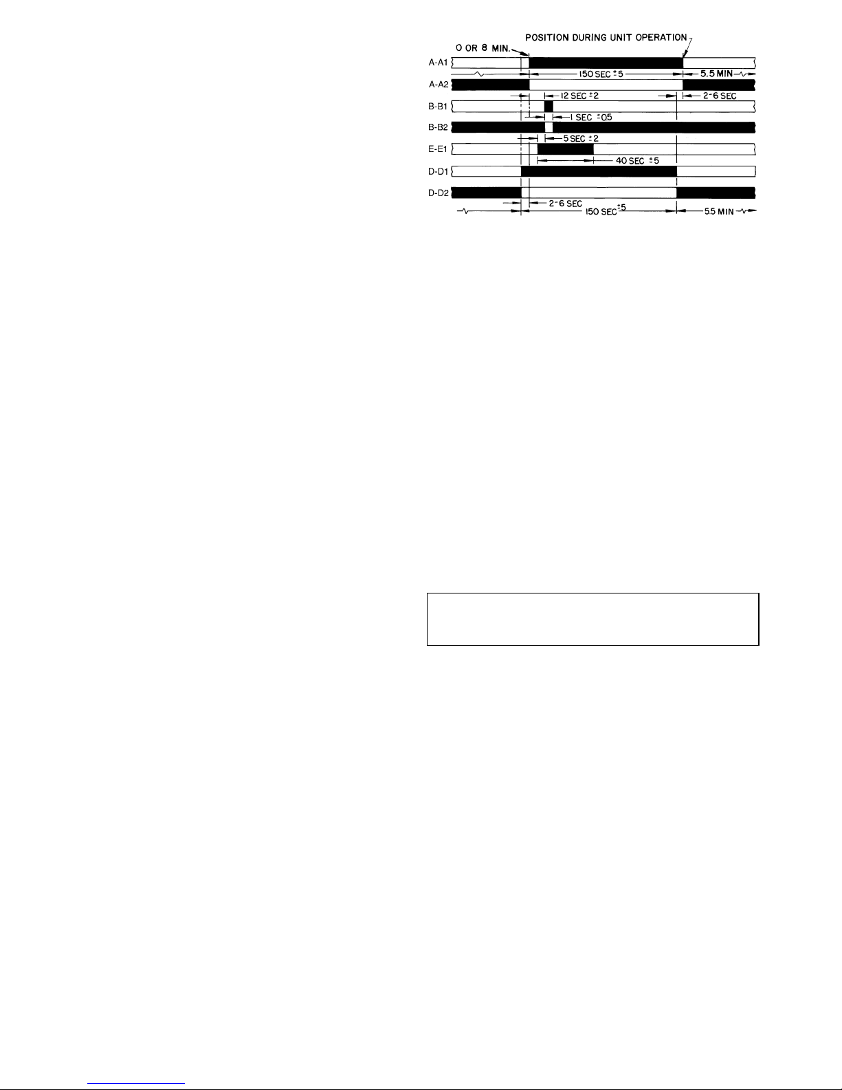
38AH044-084 DUAL-CIRCUIT UNITS; 38AH094,104 —
If circuit A operation is insufficient for the cooling requirements, the thermostat second stage TC2 closes to bring circuit B on-line for cooling. This circuit follows the same sequence of operation as the lead circuit, except a
60-second time delay relay (TDR) delays compressor start-up
for 60 seconds after the call for cooling.
38AH044-084 OPTIONALSINGLE-CIRCUIT UNITS: MODULES 124A, 124B, 134A, AND 134B
NOTE: This sequence of operation assumes that 2 thermostats control units 38AH124 or 134with one thermostat controlling each module.
If compressor A1 is insufficient for the cooling requirements, the thermostat second stage closes, which opens the
liquid line solenoid valve LLS-A2. CompressorA2starts only
after D-D2 contacts in the timer close and the suction pressure is sufficient to close the capacity control switches.
ALL UNITS — When the fan switch is set for automatic
(AUTO) operation, the indoor-fan contactor (IFC) is cycled
with the lead compressor. If the fan switch is set for continuous (CONT), the IFC is energized as long as the unit
power is on.
RestartAfterStoppage by SafetyControl— The
high-pressure switch, compressor discharge gas thermostats,
and the oil pressure switch must be reset manually by breaking the control power supply at any of the following points:
control circuit fuse, fan motor circuit breaker, or the thermostat. Restart follows the Time Guardt control delay.
Stoppage by low-pressure switch results in Time Guard
control delay, then unit attempts normal restart.
The compressor motor overcurrent protectors are manualreset circuit breakers. Reset of control circuit may also be
necessary.
IndependentRefrigerant Circuit Controls — Each
refrigeration circuit is controlled by independent circuitry.
Therefore, it is possible to maintain partial cooling capability even if one compressor is inoperable.
NOTE: The 38AH044-084 optional single-circuit units do
not have independent control circuitry.
Unit Control Box — (See Fig. 48.) Viewed facing com-
pressors, the control box is at left end of the unit. All incoming power enters through the control box. The control
box contains power components and electronic controls. Outer
panels are hingedandlatchedforeasyopening.Removescrews
to remove inner panels. Outer panels can be held open for
service and inspection by using door retainer on each panel.
Remove bottom pin from door retainer assembly, swing retainer out horizontally, and engage pin in one of the retainer
ears and the hinge assembly.
Condenser Fans — Each fan is supported by a formed
wire mount bolted to fan deck and coveredwitha wire guard.
The exposed end of fan motor shaft is protected fromweather
by grease. If fan motor must be removed for service or replacement, be sure to regrease fan shaft, and reinstall fan
guard. For proper performance, fan should be7⁄8in.
(22 mm) below top of venturi on the fan deck to top of
the fan hub for 60-Hz units, and1⁄2in. (13 mm) for 50-Hz
units. (See Fig. 49.) Tighten set screws to 15 ± 1 ft-lbs
(20 ± 1.3 N-m). Figure 49shows proper position of mounted
fan.
IMPORTANT: Check for proper fan rotation (clockwise viewed from above). If necessary to reverse, switch
leads.
NOTE: Black denotes closed contacts.
Fig. 47 — Timer Cycle
50
Page 51
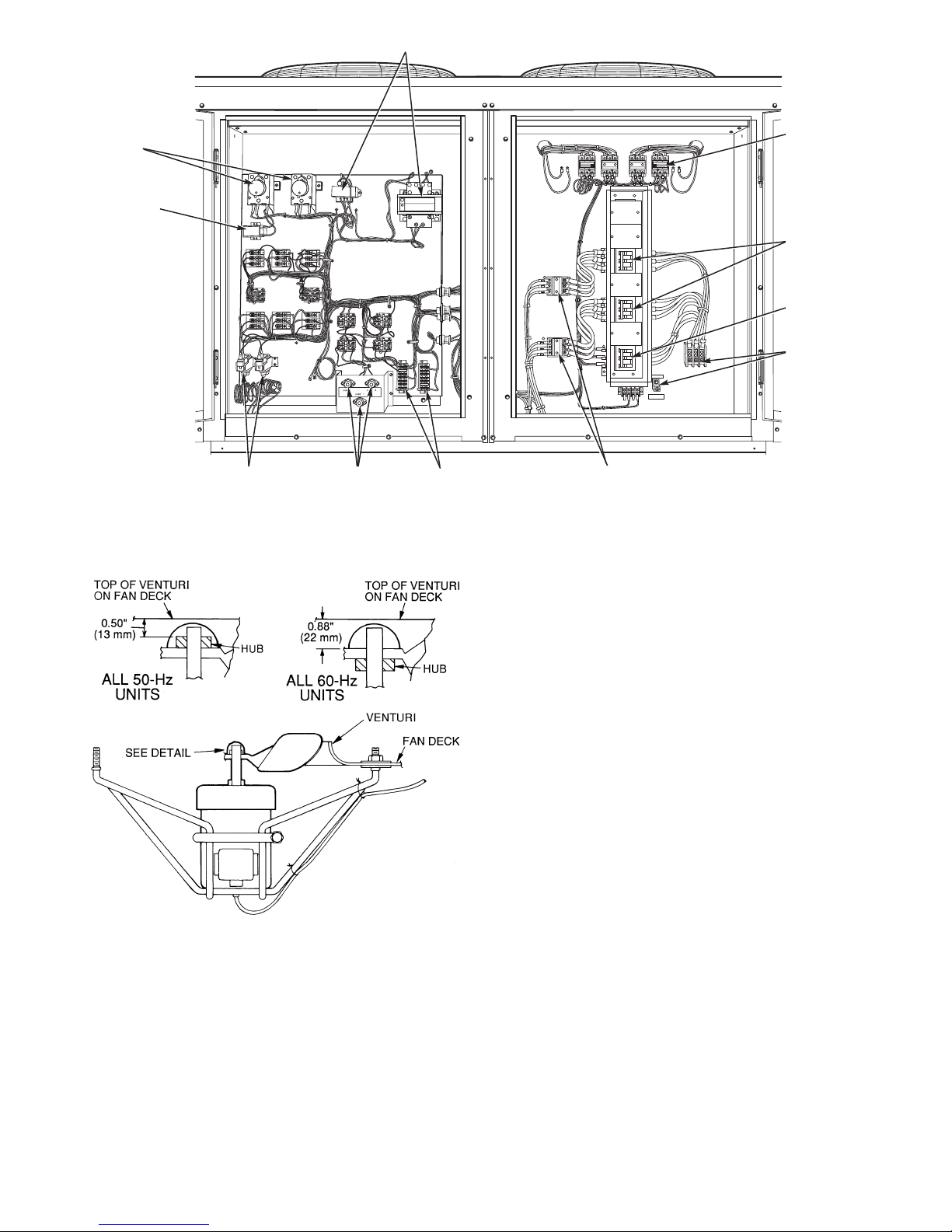
RequiredCompressor Modification for 38AH044084 Optional Single-Circuit Units, When CompressorA1 is Out —
To maintain unit operation, compressor no.1 mustbeoperable.Ifitis not operable, the following
temporary modifications must be made to keep the unit
running:
1. Change the oil pressure switch connections from com-
pressor A1 to compressor A2.
2. Connect compressor A2 into the Time Guardt circuit as
compressor A1 was originally.
3. Open compressor A1 circuit breaker.
NOTE: Make sure the crankcase heaters are energized when
compressors are off.
FAN CONTACTORS
COMPRESSOR
CIRCUIT
BREAKERS
FAN CIRCUIT
BREAKER
TERMINAL
BLOCKS
TIMERS
TIME-DELAY
RELAY
OIL PRESSURE
SWITCHES
FUSE
HOLDERS
COMPRESSOR
CONTACTORS
TERMINAL
BLOCKS
TRANSFORMERS
Fig. 48 — Unit Control Box
NOTE: Fan rotation is clockwise when viewed from top of unit.
Fig. 49 — Condenser Fan Adjustment
51
Page 52
Compressor Removal — Access to the pump end
of the compressor is from the compressor side of the unit.
Access to the motor end of the compressor is from the inside
of the unit. All compressors can be removed from the compressor side of the unit.
IMPORTANT:All compressor mounting hardwareand
support brackets removed during servicing mustbe reinstalled prior to start-up.
1. Disconnect power to unit; lockout power to compressor.
2. Close suction and discharge service valves.
3. Relieve refrigerant pressure into a refrigerant recovery
system.
4. Remove:
a. Fan-cycling pressure switch (FCPS)
b. High-pressure switch
c. Low-pressure switch
d. Oil-pressure switch
e. Discharge gas temperature switch.
5. Disconnect power wires at terminal box and disconnect
conduit.
6. Disconnect wires from crankcase heater.
7. Disconnect service valves from compressor.
NOTE: On 38AH044-084 optional single-circuit units and
units with 2 compressors per circuit, disconnect both oil
equalizer lines located on the motor barrel and on the oil
pump sump.
8. Units 38AH044-084, 124, and 134:
a. Remove 4 large screws securing compressor mount-
ing pan to unit base rail.
b. Slide compressor (on mounting pan) to outside of unit
frame; support and/or lower to ground.
c. Unbolt compressor from mounting pan and remove.
9. Units 38AH094, 104:
a. Remove4largescrewssecuringcompressortothecom-
pressor rails.
b. Lift compressor off mounting bolts and remove.
CompressorReplacement — Perform the following:
1. Reverse procedure in Compressor Removal section to end
of Step 4.
2. Reinstall service valves and safety switches, and tighten
to torques as listed:
Torque
Compressor(s)
Tighten discharge valves to —
20-25 ft-lbs ( 27- 34 N-m) 06E-250
80-90 ft-lbs (109-122 N-m) 06E-265,275,299
Tighten suction valves to —
80- 90 ft-lbs (109-122 N-m) 06E-250
90-120 ft-lbs (122-163 N-m) 06E-265,275,299
Tighten the following fittings as specified —
60 ft-lbs (81 N-m) Discharge Gas Thermostat
120 in.-lbs (13.5 N-m) High-Pressure Switch, Fan-
Cycling Pressure Switch
120 in.-lbs (13.5 N-m) Low-Pressure Switch
3. Leak-check and evacuate system, reclaim refrigerant.
4. Recharge system per pre-start-up and start-up sequences.
Recheck oil levels.
5. Energize crankcase heater for 24 hours prior to restart of
system.
OIL CHARGE — (Refer to Table 3A, 3B, 4A, or 4B.) All
units are factory charged with oil. Acceptable oil level for
each compressor is from
1
⁄8to1⁄3of sight glass (see Fig. 29,
page 38).
When additional oil or a complete charge is required, use
only Carrier-approved compressor oil.
Approved oils are:
Petroleum Specialties, Inc. — Cryol 150A(factoryoil charge)
Texaco, Inc. — Capella WF-32-150
Witco Chemical Co. — Suniso 3GS
COMPRESSOR
OIL REQUIRED
Pts L
06E-250 17 8.0
06E-265 21 9.9
06E-275 21 9.9
06E-299 19 9.0
Do not reuse drained oil, and do not use any oil that has
been exposed to atmosphere.
Adjust oil level in accordance with Start-Up, Preliminary
Oil Charge, page 38.
52
Page 53
TROUBLESHOOTING
PROBLEM SOLUTION
COMPRESSOR DOES NOT RUN
Contactor Open
1. Power off. 1. Restore power.
2. Fuses blown in field power circuit. 2. After finding cause and correcting, replace with correct
size fuse.
3. No control power. 3. Check secondary fuse(s); replace with correct type and
size. Replace transformer if primary windings receiving
power.
4. Thermostat circuit open. 4. Check thermostat setting.
5. Multi-function timer not operating. 5. Check timer for proper operation; replace if defective.
6. Compressor circuit breaker tripped. 6. Check for excessive compressor current draw. Reset
breaker; replace if defective.
7. Safety device lockout circuit active. 7. Reset lockout circuit at thermostat or circuit breaker.
8. Low-pressure switch open. 8. Check for refrigerant undercharge, obstruction of indoor
airflow, or whether compressor suction shutoff valve is
fully open. Make sure liquid line solenoid valve(s) is
open.
9. High-pressure switch open. 9. Check for refrigerant overcharge, obstruction of outdoor
airflow, air in system or whether compressor discharge
valve is fully open. Be sure outdoor fans are operating
correctly.
10. Discharge gas temperature switch open. 10. Check for open condition. Allow for reset. Replace if
defective.
11. Loose electrical connections. 11. Tighten all connections.
12. Compressor stuck. 12. See 06E compressor service literature.
Contactor Closed
1. Compressor leads loose. 1. Check connections.
2. Motor windings open. 2. See 06E compressor service literature.
3. Single phasing. 3. Check for blown fuse. Check for loose connection at
compressor terminal.
COMPRESSOR STOPS ON HIGH-PRESSURE SWITCH
Outdoor Fan On
1. High-pressure switch faulty. 1. Replace switch.
2. Airflow restricted. 2. Remove obstruction.
3. Air recirculating. 3. Clear airflow area.
4. Noncondensables in system. 4. Purge and recharge as required.
5. Refrigerant overcharge. 5. Purge as required.
6. Line voltage incorrect. 6. Consult power company.
7. Refrigerant system restrictions. 7. Check or replace filter drier, expansion valve, etc. Check
that compressor discharge valve is fully open.
Outdoor Fan Off
1. Fan slips on shaft. 1. Tighten fan hub setscrews.
2. Motor not running. 2. Check power and capacitor.
3. Motor bearings stuck. 3. Replace bearings.
4. Motor overload open. 4. Check overload rating. Check for fan blade obstruction.
5. Motor burned out. 5. Replace motor.
COMPRESSOR CYCLES ON LOW-PRESSURE SWITCH
Indoor-Air Fan Running
1. Filter drier plugged. 1. Replace filter drier.
2. Expansion valve power head defective. 2. Replace power head.
3. Low refrigerant charge. 3. Add charge. Check low-pressure switch setting.
Airflow Restricted
1. Coil iced up. 1. Check refrigerant charge.
2. Coil dirty. 2. Clean coil fins.
3. Air filters dirty. 3. Clean or replace filters.
4. Dampers closed. 4. Check damper operation and position.
Indoor-Air Fan Stopped
1. Electrical connections loose. 1. Tighten all connections.
2. Fan relay defective. 2. Replace relay.
3. Motor overload open. 3. Power supply.
4. Motor defective. 4. Replace motor.
5. Fan belt broken or slipping. 5. Replace or tighten belt.
53
Page 54
TROUBLESHOOTING (cont)
PROBLEM SOLUTION
COMPRESSOR STOPS ON OIL PRESSURE SWITCH
1. Oil level too low or too high. 1. Check oil level requirements; adjust oil level until sight
glass is filled
1
⁄8to1⁄3when running.
2. Compressor is short cycling. 2. Check for
a) Thermostat location and operation.
b) Safety device lockout circuit operation.
c) End-of-cycle control and timer operation.
d) Low-pressure switch and relay operation.
3. Crankcase heater off. 3. Check relay operation; replace crankcase heater(s), if
defective.
4. Low refrigerant charge. 4. Adjust charge as required.
5. Refrigerant floodback. 5. Adjust TXV superheat.
6. Evaporator coil is blocked or iced. 6. Check and correct as required.
7. Evaporator fan not operating. 7. Check and correct as required.
8. Distributor and/or TXV too large. 8. Check sizing at design conditions; change if incorrect
for current application.
9. Suction riser too large. 9. Check line sizing at minimum design condition; change
piping if incorrect.
10. Defective oil pressure switch. 10. Check switch for proper operation; check capillary lines
for plugged lines.
11. Plugged oil pump inlet screen. 11. Clean oil pump screen.
12. Faulty oil pump drive segment. 12. Replace drive segment.
13. Worn oil pump. 13. Replace bearing head assembly.
14. Worn compressor bearings. 14. Replace compressor; see 06E service instructions.
COMPRESSOR RUNNING BUT COOLING INSUFFICIENT
Suction Pressure Low
1. Refrigerant charge low. 1. Add refrigerant.
2. Head pressure low. 2. Check refrigerant charge.
Check outdoor-air fan thermostat settings.
3. Air filters dirty. 3. Clean or replace filters.
4. Expansion valve power head defective. 4. Replace power head.
5. Indoor coil partially iced. 5. Check low-pressure setting.
6. Indoor airflow restricted. 6. Remove obstruction.
Suction Pressure High
1. Unloaders not functioning. 1. Check unloader adjustments.
Check unloader setting.
2. Compressor valve defective. 2. See 06E compressor service literature.
3. Heat load excessive. 3. Check for open doors or windows in vicinity of fan coil.
UNIT OPERATES TOO LONG OR CONTINUOUSLY
1. Low refrigerant charge. 1. Add refrigerant.
2. Control contacts fused. 2. Replace control.
3. Air in system. 3. Purge and evacuate system.
4. Partially plugged expansion valve or filter drier. 4. Clean or replace.
SYSTEM IS NOISY
1. Piping vibration. 1. Support piping as required.
2. Compressor noisy. 2. Check valve plates for valve noise. Replace compressor
if bearings are worn.
COMPRESSOR LOSES OIL
1. Leak in system. 1. Repair leak.
2. Crankcase heaters not energized during shutdown. 2. Check wiring and relays. Check heater and replace if
defective.
3. Improper interconnecting piping design. 3. Check piping for oil return. Replace if necessary.
FROSTED SUCTION LINE
1. Expansion valve admitting excess refrigerant. 1. Adjust expansion valve.
HOT LIQUID LINE
1. Shortage of refrigerant due to leak. 1. Repair leak and recharge.
2. Expansion valve opens too wide. 2. Adjust expansion valve.
FROSTED LIQUID LINE
1. Restricted filter drier. 1. Remove restriction or replace.
COMPRESSOR WILL NOT UNLOAD
1. Defective unloader. 1. Replace unloader.
2. Defective capacity control solenoid valve (if used). 2. Replace valve.
3. Miswired capacity control liquid line solenoid (if used). 3. Rewire correctly.
4. Weak, broken, or wrong valve body spring. 4. Replace spring.
COMPRESSOR WILL NOT LOAD
1. Miswired capacity control liquid line solenoid (if used). 1. Rewire correctly.
2. Defective capacity control solenoid valve (if used). 2. Replace valve.
3. Plugged strainer (high side). 3. Clean or replace strainer.
4. Stuck or damaged unloader piston or piston ring(s). 4. Clean or replace the necessary parts.
Copyright 1998 Carrier Corporation
Manufacturer reserves the right to discontinue, or change at any time, specifications or designs without notice and without incurring obligations.
Book 1
Tab 3a
PC 111 Catalog No. 563-704 Printed in U.S.A. Form 38AH-15SI 54 10-98 Replaces: 38AH-14SI
Page 55
START-UP CHECKLIST
A. Preliminary Information
OUTDOOR:MODELNO. SERIALNO.
INDOOR: AIR HANDLER MANUFACTURER
MODEL NO. SERIAL NO.
ADDITIONAL ACCESSORIES
B. Pre-Start-Up
OUTDOOR UNIT
IS THERE ANY SHIPPING DAMAGE? (Y/N)
IF SO, WHERE:
WILL THIS DAMAGE PREVENT UNIT START-UP? (Y/N)
CHECK POWER SUPPLY. DOES IT AGREE WITH UNIT? (Y/N)
HAS THE GROUND WIRE BEEN CONNECTED? (Y/N)
HAS THE CIRCUIT PROTECTION BEEN SIZED AND INSTALLED PROPERLY? (Y/N)
ARE THE POWER WIRES TO THE UNIT SIZED AND INSTALLED PROPERLY? (Y/N)
HAVE COMPRESSOR HOLDDOWN BOLTS BEEN LOOSENED? (Y/N)
CONTROLS
ARE THERMOSTAT(S) AND INDOOR FAN CONTROL WIRING
CONNECTIONS MADE AND CHECKED? (Y/N)
ARE ALL WIRING TERMINALS (including main power supply) TIGHT? (Y/N)
HAVE CRANKCASE HEATERS BEEN ENERGIZED FOR 24 HOURS? (Y/N)
INDOOR UNIT
HAS WATER BEEN PLACED IN DRAIN PAN TO CONFIRM PROPER DRAINAGE? (Y/N)
ARE PROPER AIR FILTERS IN PLACE? (Y/N)
HAVE FAN AND MOTOR PULLEYS BEEN CHECKED FOR PROPER ALIGNMENT? (Y/N)
DO THE FAN BELTS HAVE PROPER TENSION? (Y/N)
PIPING
ARE LIQUID LINE SOLENOID VALVES LOCATED AT THE EVAPORATOR COILS AS REQUIRED? (Y/N)
HAVE LEAK CHECKS BEEN MADE AT COMPRESSORS, CONDENSERS, EVAPORATORS,
TXVs (Thermostatic Expansion Valves) SOLENOID VALVES, FILTER DRIERS, AND FUSIBLE PLUGS
WITH A LEAK DETECTOR? (Y/N)
LOCATE, REPAIR, AND REPORT ANY LEAKS.
HAVE ALL COMPRESSOR SERVICE VALVES BEEN FULLY OPENED (BACKSEATED)? (Y/N)
ARE THE COMPRESSOR OIL SIGHT GLASSES SHOWING ABOUT1⁄2FULL? (Y/N)
CHECK VOLTAGE IMBALANCE
LINE-TO-LINE VOLTS: AB V AC V BC V
(AB + AC + BC)/3 = AVERAGE VOLTAGE = V
MAXIMUM DEVIATION FROM AVERAGE VOLTAGE = V
VOLTAGE IMBALANCE = 100 X (MAX DEVIATION)/(AVERAGE VOLTAGE) = %
IF OVER 2% VOLTAGE IMBALANCE, DO NOT ATTEMPT TO START SYSTEM!
CALL LOCAL POWER COMPANY FOR ASSISTANCE.
CL-1
Page 56
C. Start-Up
CHECK EVAPORATOR FAN SPEED AND RECORD.
CHECK CONDENSER FAN SPEED AND RECORD.
AFTER AT LEAST 10 MINUTES RUNNING TIME, RECORD THE FOLLOWING MEASUREMENTS:
COMP A1 COMP A2 COMP B1 COMP B2
OIL PRESSURE
SUCTION PRESSURE
SUCTION LINE TEMP
DISCHARGE PRESSURE
DISCHARGE LINE TEMP
ENTERING CONDENSER AIR TEMP
LEAVING CONDENSER AIR TEMP
EVAP ENTERING AIR DB TEMP
EVAP ENTERING AIR WB TEMP
EVAP LEAVING AIR DB TEMP
EVAP LEAVING AIR WB TEMP
COMPRESSOR AMPS (L1)
COMPRESSOR AMPS (L2)
COMPRESSOR AMPS (L3)
CHECK THE COMPRESSOR OIL LEVEL SIGHT GLASSES; ARE THE SIGHT GLASSES SHOWING
OIL LEVEL AT1⁄8TO1⁄3FULL? (Y/N)
NOTES:
----------------------------------------------------------------------------------------
CUT ALONG DOTTED LINE CUT ALONG DOTTED LINE
Copyright 1998 Carrier Corporation
Manufacturer reserves the right to discontinue, or change at any time, specifications or designs without notice and without incurring obligations.
Book 1
Tab 3a
PC 111 Catalog No. 563-704 Printed in U.S.A. Form 38AH-15SI CL-2 10-98 Replaces: 38AH-14SI
 Loading...