

Page 1
HEATING & COOLING
38AH024-034
Air-Cocled Condensing Units
50/60 Hz
Installation, Start-up and Service
Instructions
CONTENTS
Page
SAFETY CONSIDERATIONS .. .
BEFORE INSTALLATION
Rigging .............................................................. 1
Placing Unit ....................................................... 1
Mounting Unit
Compressor Mounting
INSTALLATION
Refrigerant Piping Connections
Solenoid Drop Refrigerant Control
Filter Drier and Moisture Indicator
Receiver
Piping Procedure ............................................... 5
Power Supply
Power Wiring ..................................................... 7
PRE-START-UP ................................................ 14
System Check
Leak Test and Dehydration............................... 14
Preliminary Charge
START-UP....................................................... 14-16
Preliminary Checks
Preliminary Oil Charge
Start Unit
Adjust Refrigerant Charge
Check Compressor Oil Level
Final Checks..................................................... 15
SEQUENCE OF OPERATION
Single Air Handler —
2-Stage Cool Thermostat ............................... 17
Two Air Handlers —
Two 2-Stage Cool Thermostats
(One Per Air Handler)
Restart
Causes of Complete Unit Shutdown
SERVICE ....................................................... 18-20
Access for Servicing .......................................... 18
Fan Adjustment
Oil Charge
Liquid Shutoff/Charging Valve
Capacity Control, Suction Pressure-
Capacity Control, Electrically Operated
Oil Pressure Safety Switch (OPS)
Compressor Protection
High-Pressure Switches
Low-Pressure Switches
Winter Start Control ........................................... 20
Head Pressure Control
TROUBLESHOOTING.....................................21-23
START-UP CHECKLIST
..............................................................
Actuated Unloaders
Unloaders (Variable Air Volume
Factory-Installed Option Units)
....................................................
.......................................
..............................................
............................................................
....................................................
...................................................
...........................................
...........................................
......................................
...........................................................
....................................
.................................................
.........................................................
.......................................
.....................................
...................................
....................................
.....................................
.....................
.............................
................................
.........................
.....................
......................
................................
............................
.........................
.................
..........................
......................
....................
CL-1, CL-2
1
1-5
5
5
5-13
5
5
5
5
7
14
14
14
14
14
15
15
17
17
17
17
18
18
18
18
18
18
18
18
18
20
SAFETY CONSIDERATIONS
Installing, starting up, and servicing air-conditioning equip
ment can be hazardous due to system pressures, electrical
components, and equipment location (roofs, elevated struc
tures, etc.)
Only trained, qualified installers and service mechanics
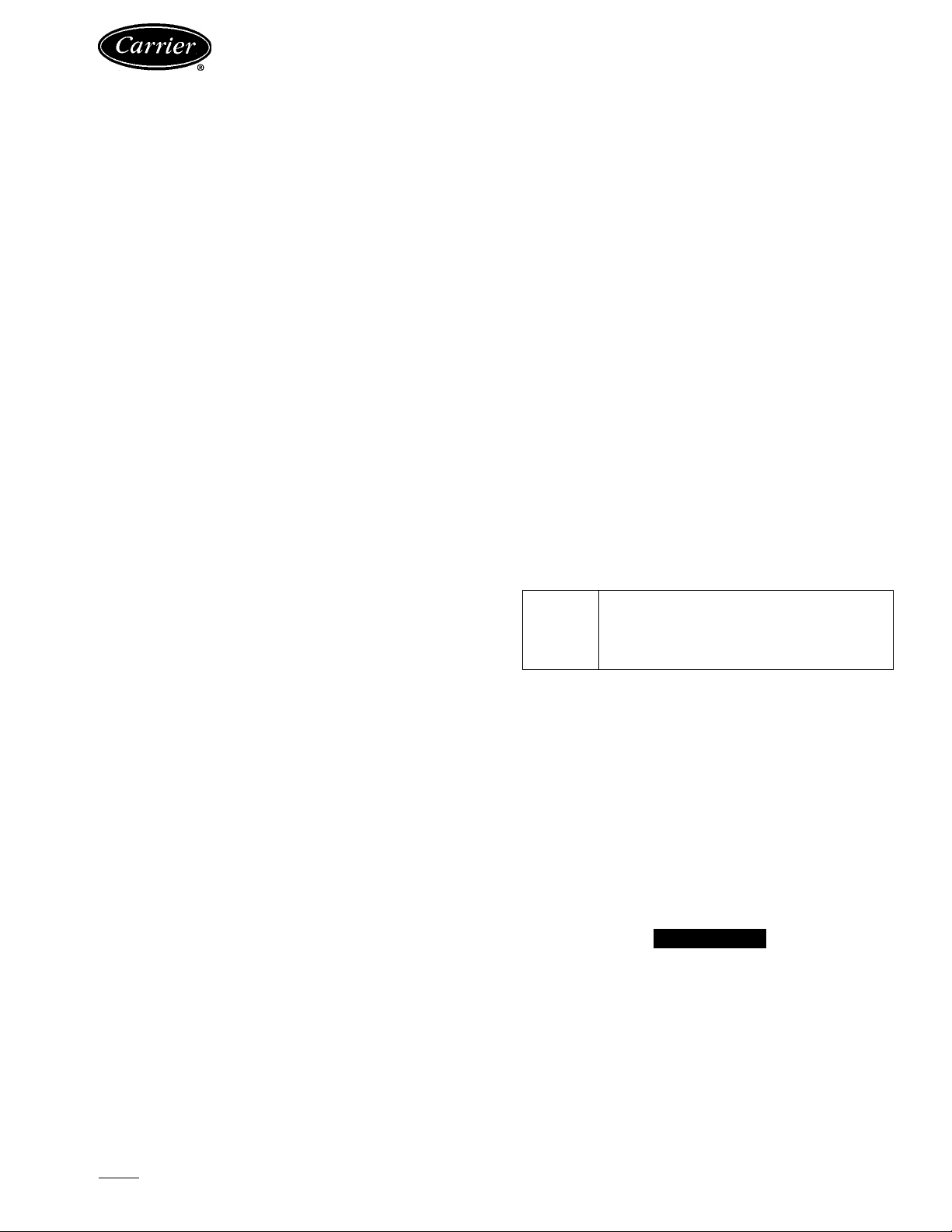
should install, start up, and service this equipment (Fig. 1).
Untrained personnel can perform basic maintenance func
tions such as cleaning coils. All other operations should be
performed by trained service personnel.
When working on the equipment, observe precautions in
the literature and on tags, stickers, and labels attached to
the equipment.
• Follow all safety codes.
• Wear safety glasses and work gloves.
• Keep quenching cloth and fire extinguisher nearby when
brazing.
• Use care in handling, rigging, and setting bulky
equipment.
• See Table lA or IB for Physical Data.
S ilii
¿5
ELECTRIC SHOCK HAZARD
Open all remote disconnects before ser
vicing this equipment.
BEFORE INSTALLATION
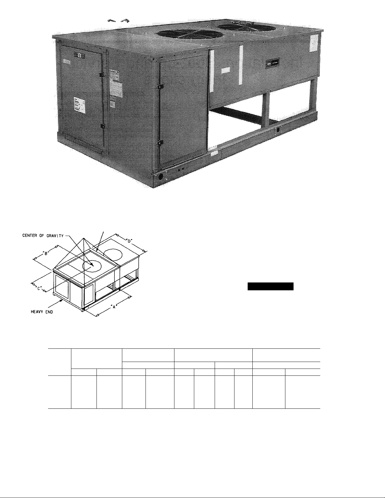
Rigging — Preferred method is with spreader bars from
above the unit. Use 2-in. (50 mm) OD pipe or hooks in lift
ing holes. Rig with 4 cables and spreader bars. All panels
must be in place when rigging. See rigging label on unit for
details concerning shipping weights, distance between lift
ing holes, center of gravity, and spreader bar dimensions.
See Fig. 2.
If overhead rigging is not possible, place condensing unit
on skid or pad for rolling or dragging. When rolling, use
minimum 3 rollers. When dragging, pull the pad. Do not
apply force to the unit. When in final position, raise from
above to lift unit off pad.
A CAUTION
All panels must be in place when rigging. Do not fork
units if no skid is supplied. If unit has skid, truck from
sides only.
Placing Unit — There must be 4 ft (1200 mm) for ser
vice and for unrestricted airflow on all sides of unit, and a
minimum of 8 ft (2440 mm) clear air space above unit. For
multiple units, allow 8 ft (2440 mm) separation between
units for airflow and service.
Manufacturer reserves the right to discontinue, or change at any time, specifications or designs without notice and without incurring obligations.
Book 11 PC 111 Catalog No 563-739 Printed in U.S A Form 38AH-7SI Pg 1 4-93 Replaces: New
Tab 3a
Page 2
UNIT
38AH
024
024C
028
028C
034
034C
3/4 IN. Cl9 MM) NOTCHES
IN END OF SPREADERS
MAX SHIPPING
WEIGHT
lbs
2240
2403
2300
2463
2360
2577
kgs in.
1018
1092
1045
1120
1073
1171
Fig. 1 - Model 38AH (Size 024 Shown)
NOTES:
1. Use 2 in OD {50 mm) pipe or hooks in lifting holes
2. Rig with 4 cables and spread with two ‘D’ long and two ‘A’ long 2
X 4 in. (50 X 100 mm) or equal.
3. Run the rigging cables to a central suspension point so that the
angle from the horizontal is not less than 45 degrees
4 Shipping weights include skid
All panels must be in place with rigging.
NOTICE TO RIGGERS
LIFTING HOLES
‘A’
mm in.
81
2057
CENTER OF GRAVITY
‘B’ ‘C’ ‘D’
40 0
43.0
39 3
42.3
41 0
44 0
mm
1016
1092
997
1073
1041
1118
in.
32.8
A CAUTION
DISTANCE BETWEEN
RIGGING CABLES
mm in. mm
832
73 5
1867
Fig. 2 — Rigging Label
Page 3
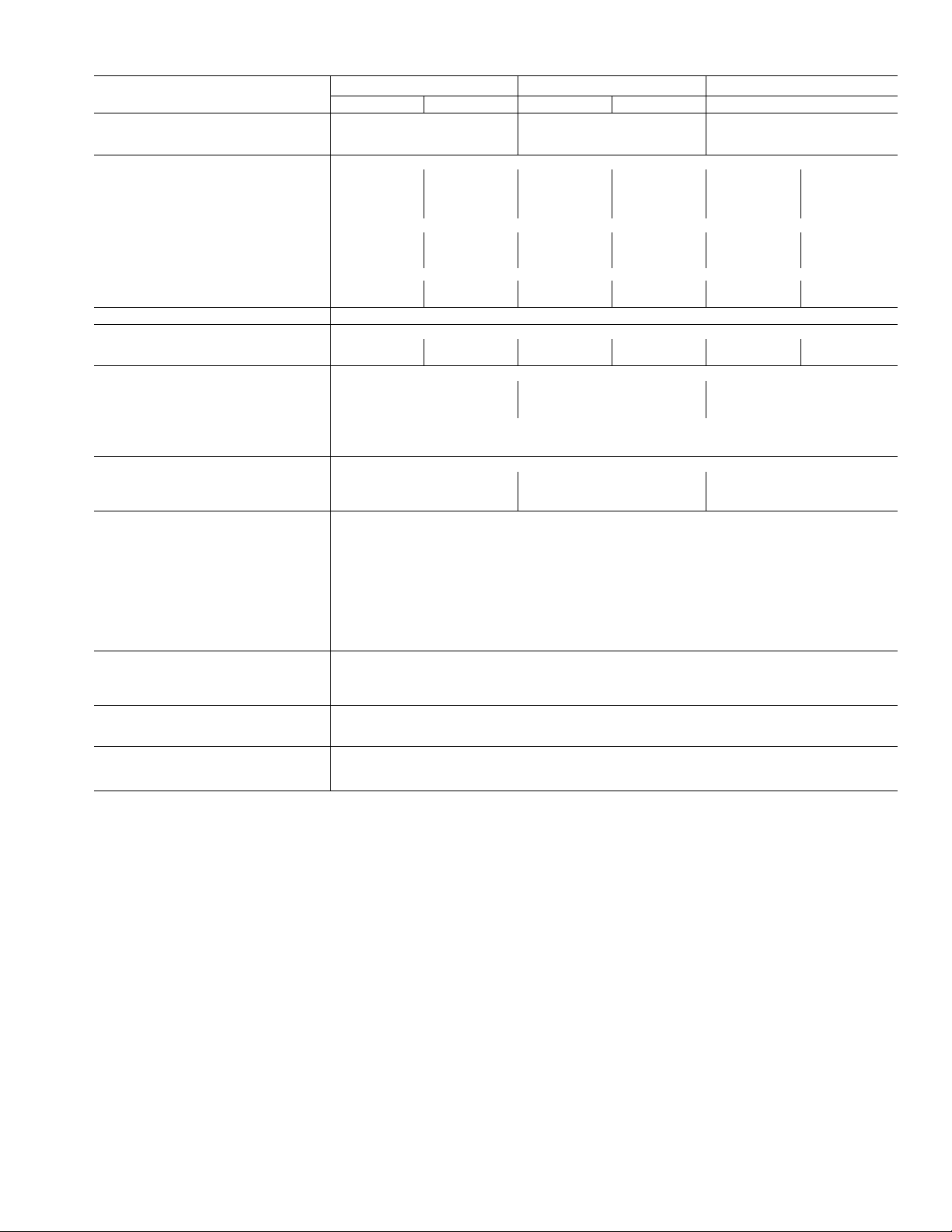
Table 1A — Physical Data — English
6
66*
33t
76
58
024
6
1750 1750
1450 1450
__
—
—
—
UNIT 38AH
OPERATING WEIGHT (lb)
With Alurninum-FIn Coil 1760 1820
With Copper-Fin Coil 1923
COMPRESSOR
Type
Quantity Cylinders (ea)
Speed (rpm) — 60 Hz
Capacity Steps
(FIOP or Асу) - %
Unloader Setting (psig)
— Load
— Unload
- 50 Hz
- %
- %
Circuit 1 Circuit 2 Circuit 1
06DH824 06DA824 06DH328 06DA328
1750
1450
100 100 100 100
OIL CHARGE PER CIRCUIT (Pt)
REFRIGERANT, TYPE**
Shipping Charge (lb)
Operating Charge, Typical (lb)
CONDENSER FANS
Quantity...Dia (in.)
Nominal Hp
Nominal Airflow (cfm) 16,700
Speed (rpm) — 60 Hz
Watts (ea) - 50/60 Hz
CONDENSER COIL
Rows...Fins/in.
Total Face Area (sq ft)
- 50 Hz
Storage Cap. (Ib)tt
CONTROLS
Pressurestat (psig)
High Pressure
Cutout
Cut-in
Low Pressure
Cutout
Cut-in
Oil Pressure
Cutout (Diff)
Cut-in (Diff)
FAN CYCLING CONTROLS
No. 2 Fan:
Temp Close (F)
Temp Open (F)
PRESSURE RELIEF
Location
Temp (F)
CONNECTIONS (Sweat) (ea ckt)
Suction — in. OD
3 3 3
20 20 20 20
2..
30
1 0
2.. 19
39 20 39 20 39.20
37 7
Liquid — in. OD
LEGEND
Diff — Differential
FlOP — Factory-Installed Option
VAV — Variable Air Volume
'Standard unit — single suction pressure-actuated unioader on compressor no 1
tVAV FiOP — doubie eiectrically actuated unloaders on compressor no 1
"With 25 ft of interconnecting piping
ttCondenser 80% full of liquid R-22 at 120 F
028
Circuit 2 Circuit 1 Circuit 2
1982
Reciprocating Semi-Hermetic
6 6
66*
33t
Factory
76
58
1750
1450
—
—
Installed
—
— 58
10
R-22
Propeller Type — Direct Driven
Enhanced Copper Tubes, Aluminum Lanced Fin
2 30 2. .30
1 0 1.0
16,700 15,700
1140
950
1550
2
3 3 3
19
37.7 56.6
± 7
426
320 ± 20
27
± 3
44 ± 5
Manual Reset
60
8.8
70 ± 3
60 ± 3
Liquid Line, Suction Line, Compressor
Fusible Plug
210
1%
%
034
1880
2097
06DH328 06DA537
6 6
1750 1750
1450
100 100
66*
33t
76
1450
—
—
—
—
25 25
3.. 17
Page 4
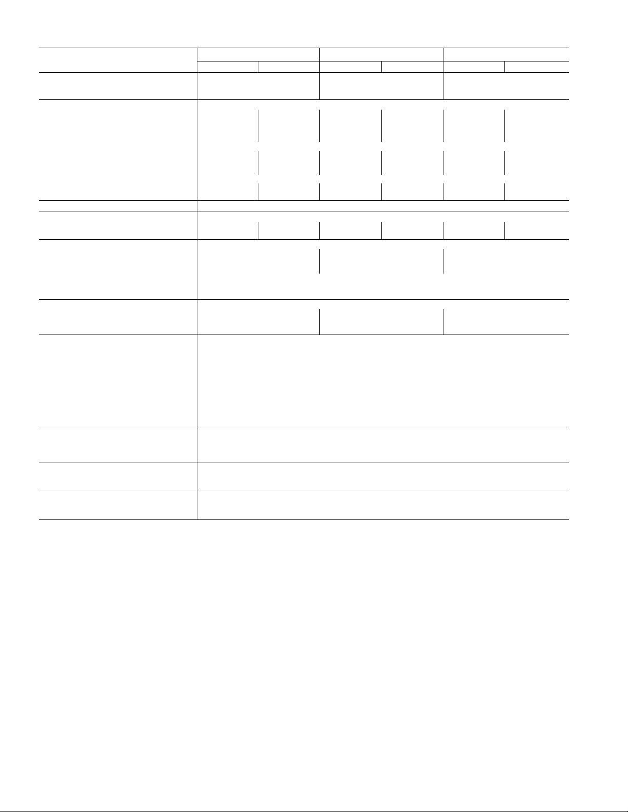
Table IB — Physical Data — SI
UNIT 38AH
OPERATING WEIGHT (kg)
With Aluminum-Fin Coii
With Copper-Fin Coii
COMPRESSOR
Type
Quantity Cyiinders (ea)
Speed (r/s) — 60 Hz
Capacity Steps
(FlOP or Асу) - %
Unloader Setting (kPa)
— Load
— Unioad
- 50 Hz
- %
- %
Circuit 1
06DH824
29.2
24.3 24 3 24 3 24.3
100 100 100 100
024 028
Circuit 2 Circuit 1 Circuit 2
798 3
872 3
06DA824 06DH328
6 6
66*
33t
524
400
29.2 29.2
—
—
—
— 400
OiL CHARGE PER CIRCUIT (L)
REFRIGERANT, TYPE**
Shipping Charge (kg)
Operating Charge, Typicai (kg)
CONDENSER FANS
Quantity...Dia (mm)
Nominal Hp
Nominal Airflow (L/s)
Speed (r/s) — 60 Hz
Watts (ea) — 50/60 Hz
CONDENSER COIL
Rows...Fins/m
- 50 Hz
Total Face Area (sq m)
Storage Cap. (kg)tt
CONTROLS
Pressurestat (kPa)
High Pressure
Cutout
Cut-in
Low Pressure
Cutout
Cut-in
Oil Pressure
Cutout (Diff)
Cut-in (Diff)
FAN CYCLING CONTROLS
No. 2 Fan;
Temp Close (C)
Temp Open (C)
PRESSURE RELIEF
Location
Temp (C)
CONNECTIONS (Sweat) (ea ckt)
Suction — in. OD
Liquid — in. OD
1 36
9.1 9.1
2 ..762
7870
2 ..748
174
1 36 1.36 1.36
1.0
Enhanced Copper Tubes, Aluminum Lanced Fin
3.64 3 64
LEGEND
Diff — Differential
Flop — Factory-Installed Option
VAV — Variable Air Volume
‘Standard unit — single suction pressure-actuated unloader on compressor no. 1
tVAV FlOP — double electrically actuated unloaders on compressor no 1
“With 7.6 m of interconnecting piping
ttCondenser 80% full of liquid R-22 at 48.8 C.
825 6
899.0
Reciprocating Semi-Hermetic
6
66*
33t
Factory
524
06DA328
Installed
6
29 2
_
—
—
4.73
R-22
9 1 9.1
Propelier Type — Direct Driven
2 762
1.0
7870
19
16
1550
2
748
174
2937 ± 48
2206 ± 138
± 21
186
± 34
303
Manuai Reset
41.4
60.7
21 1 ± 1.6
± 1.6
156
Liquid Line, Suction Line, Compressor
Fusible Plug
99
1%
%
Circuit 1
06DH328
6
29.2
24.3
100
66*
33t
524
400
1 36
11.4
034
853 0
951.2
2...762
1.0
7400
3 670
3.64
26.0
Circuit 2
06DA537
6
29 2
24.3
100
—
—
—
—
1.36
11.4
Page 5
Mounting Unit — When unit is in proper location, use
of mounting holes in base rails is recommended for secur
ing unit to supporting structure, or for mounting unit on
vibration isolators if required. Fasteners for mounting unit
are field supplied. Be sure to mount unit level to ensure
proper oil return to compressors.
Compressor Mounting — As shipped, compressor
is held down by 4 bolts. After unit is installed, loosen each
bolt until the snubber washer can be moved with finger pres
sure. See Fig. 3.
SNUBBER FLANGED
WASHER
NEOPRENE
SNUBBER
COMPRESSOR FOOT
ISOLATION SPRING
Fig. 3 — Compressor Mounting
INSTALLATION
Refrigerant Piping Connections — Line sizes de
pend on length of piping required between condensing unit
and evaporator. See Table 2A or 2B. It is important to con
sider liquid lift and compressor oil return. Refer to Part 3 of
Carrier System Design Manual for line sizing information,
and Fig. 4 for recommended piping details.
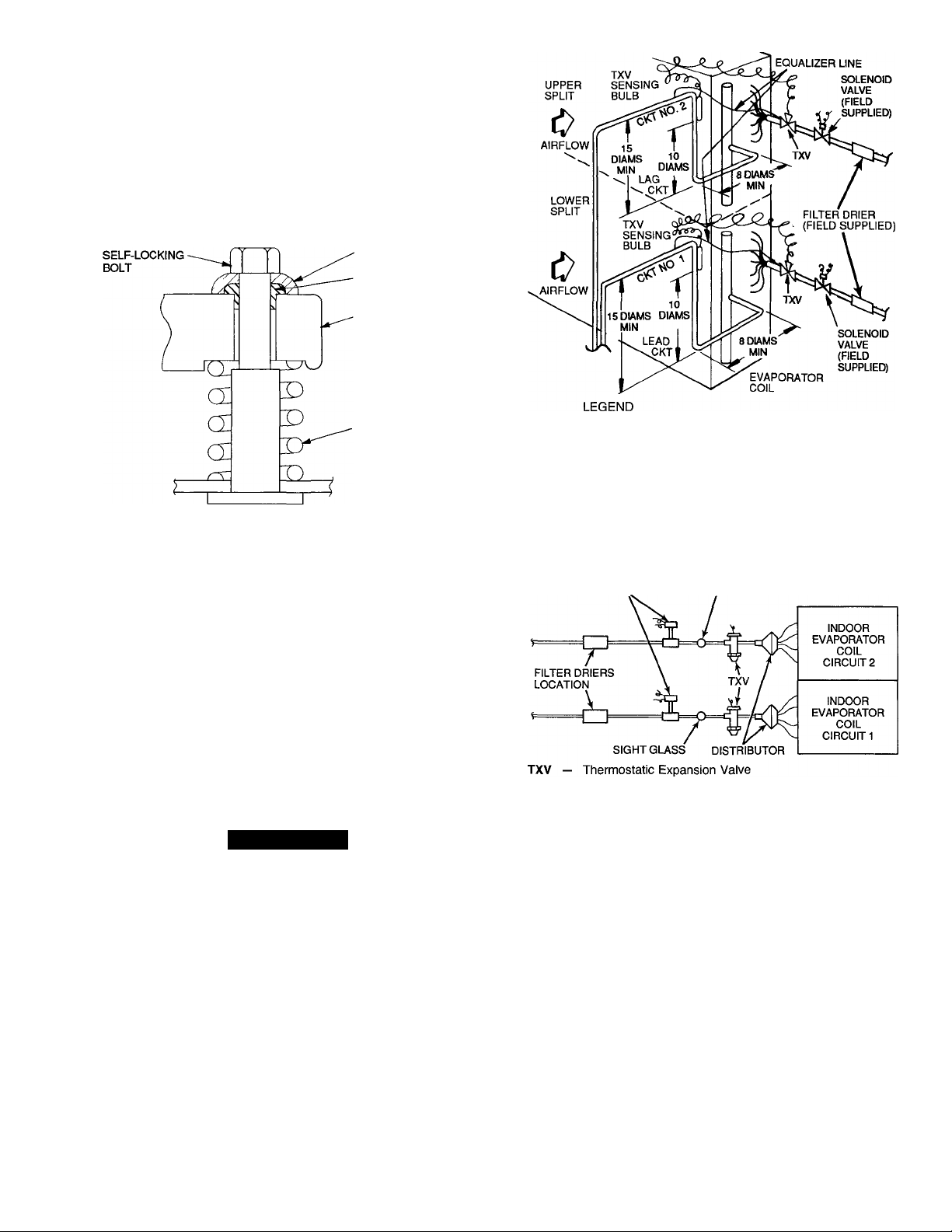
Solenoid Drop Refrigerant Control — All units
are factory wired to operate on solenoid drop refrigerant
control. A field-supplied liquid line solenoid valve must be
installed in the liquid line ahead of the indoor coil. See
Fig. 5. Wires from solenoid valve do not need to be in con
duit as coil voltage is 24 v (class 2 circuit).
A WARNING
Failure to properly install liquid line solenoid at the in
door unit as described, without Carrier authorization,
may VOID warranty.
Filter Drier and Moisture Indicator — Every unit
should have a filter drier and a sight glass (moisture indi
cator) field installed. Select the filter drier for maximum
unit capacity and minimum pressure drop. Figure 5 shows
recommended locations of filter drier(s) and sight glass(es).
Complete the refrigerant piping from the evaporator to the
condenser before opening the liquid and suction lines at the
condensing unit.
Receiver — No receiver is provided with the unit; it is
recommended that one not be used.
Piping Procedure — Do not remove run-around pipe
from suction and liquid line stubs until piping connections
TXV — Thermostatic Expansion Vaive
NOTES:
1. Lower section is first on and last off.
2. For more complete piping information, refer to Carrier System
Design Manual, Part 3, or E20-II refrigerant piping computer
program
Fig. 4 — Suction Line Piping to Unit with
2-Section Coil Split
fieLd-supplied
SOLENOID VALVE
SIGHT GLASS
Fig. 5 — Liquid Line Solenoid Valve,
Filter Drier(s), and Sight Glass Locations
are ready to be made. Pass nitrogen or other inert gas through
piping while brazing, to prevent formation of copper oxide.
Install field-supplied thermostatic expansion valve (TXV)
in liquid line ahead of each evaporator section.
SUCTION PIPING AT EVAPORATOR AND TXV BULB
LOCATION (See Fig. 5) — The purpose of these recom
mendations is to achieve good mixing of the refrigerant leav
ing the evaporator suction header for proper sensing by the
TXV bulb.
1. A minimum of two 90 degree elbows must be installed
upstream of the expansion valve bulb location.
2. The TXV sensing bulb should be located on a vertical
riser where possible. If a horizontal location is neces
sary, secure the bulb at approximately the 4 o’clock
position.
Copy continued on page 7.
Page 6
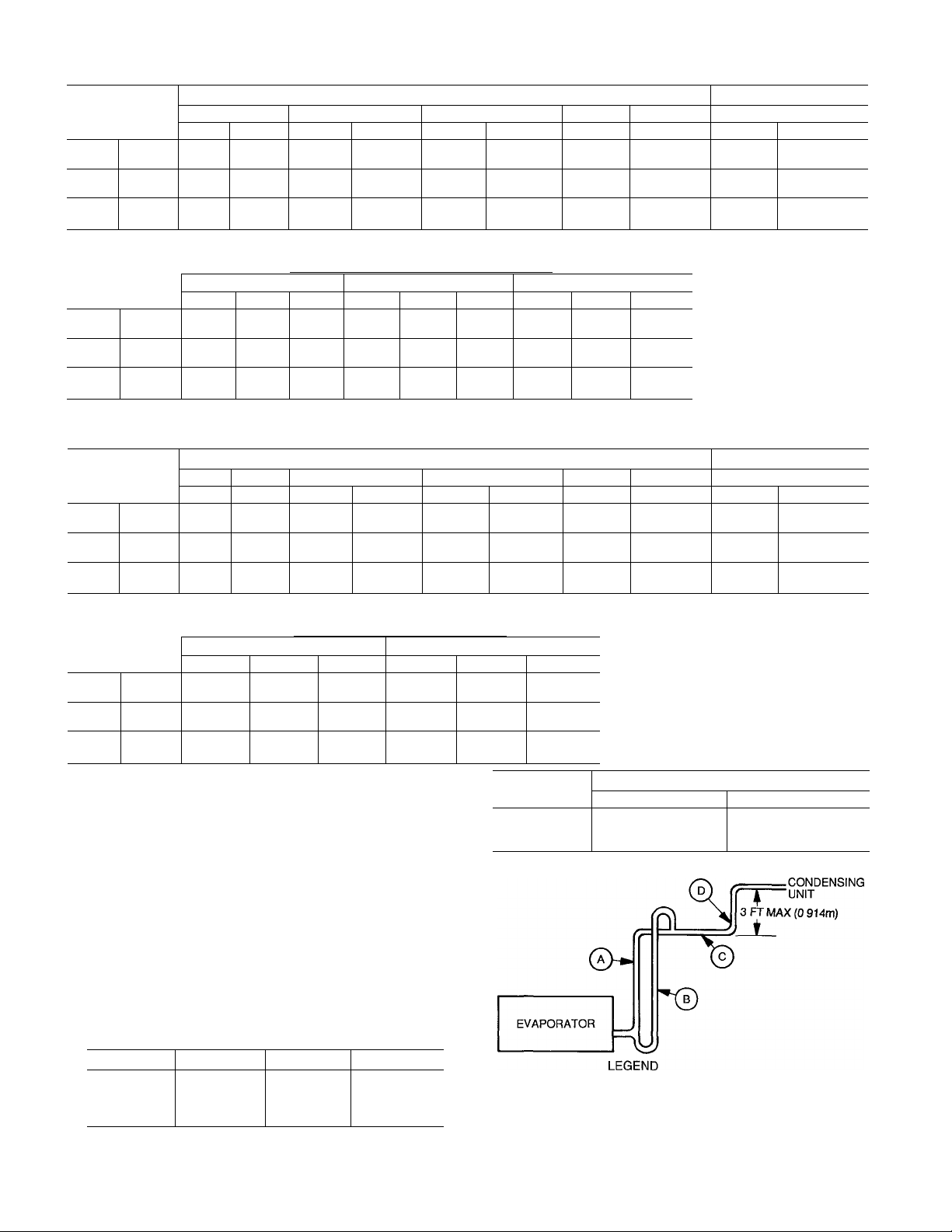
Table 2A — Refrigerant Piping Sizes — 60 Hz
SINGLE SUCTION RISERS
LENGTH OF INTERCONNECTING PIPING FOR EACH CIRCUIT - ft
UNIT 38AH
024
028
034
Ckt 1
Ckt2
Ckt 1
Ckt 2
Ckt 1
Ckt 2
0-25 (0-7.6)
L
V2 1Ve
V2 1Ve
Vz
V2
Vz
Vz 1%
s
1У8 %
1У8 %
1У8 %
25-50 (7.6-15.2) 50-75 (15.2-22.9) 75-100
L S L s L
% 1% %
% 1% %
1% %
13/8
13/8
% 1% У8
DOUBLE SUCTION RISERS
LENGTH OF INTERCONNECTING PIPING - ft (m)
UNIT 38AH
024
028
034
Ckt 1
Ckt 2
Ckt 1
Ckt 2
Ckt 1
Ckt 2
50-75 (15.2-22.9)
A
_ _ —
—
__
— —
1Уе
В С
—
_
13/8
- —
—
_
“
15/8
— — —
75-100 (22.9-30.5)
A
1Ув
1У8
1Уе
1Уе
1У8
В С
13/в
13/8 13/8
13/8
13/8
13/8
Table 2B — Refrigerant Piping Sizes — 50 Hz
SINGLE SUCTION RISERS
LENGTH OF INTERCONNECTING PIPING FOR EACH CIRCUIT - ft
UNIT 38АН
0-25
(0-7.6)
L s
024
028
034
Ckt 1
Ckt 2
Ckt 1
Ckt 2
Ckt 1 Vz V/a
Ckt 2 Vz V/s
У2
У2
Vz
V2
1У8 3/e
1У8 3/8
1У8
1Va
DOUBLE SUCTION RISERS
LENGTH OF INTERCONNECTING PIPING - ft (m)
UNIT 38AH 75-100 (22.9-30.5)
A
024
028
034
Ckt 1
Ckt 2
Ckt 1
Ckt 2
Ckt 1 1У8
Ckt 2
LEGEND
L — Liquid Line
S — Suction Line
‘Double suction riser required if evaporator is below condensing
unit and 2 unloaders are used
tDouble suction riser required if evaporator is below condensing
unit and compressor is equipped with 2 unloaders. Note the only
time circuit no. 2 may be equipped with 2 unloaders is if it is serv
ing its own air handler and the unit does not require low ambient
operation (Motormaster® III control).
“Double suction riser required if evaporator is below condensing
unit and compressor has one or more unloaders
NOTES:
1. All line sizes are inches OD.
2. Standard unit comes with one pressure-operated unloader on cir
cuit no. 1. If unit serves one air handler, an additional unloader
may be field installed on circuit no 1 compressor only. If the unit
serves 2 separate air handlers and low-ambient operation is re
quired (Motormaster III control), each circuit’s compressor may
be equipped with only one unloader.
3 Equivalent line sizes in mm are as follows;
in. mm in.
У2
3/8 15.9
У8 22.2
1У8 28.6
1У8
1У8
1У8
1У8
1У8
12.7
25-50 (7.6-15.2) 50-75 (15.2-22.9) 75-100
L S L
13/8
13/8
%
3/s
3/8
3/8
13/8
13/8
13/8
13/8
В c A
13/8
13/e
13/8
13/8
13/8 13/8 13/8
13/8 13/8 13/e
13/8
13/8
13/8
15/e
mm
13/8 34 9
13/8 41.3
2Ув 54 0
1У8
1У8
1У8
IVe
13/8
13/8
13/8
%
%
13/8
13/8*
15/8
13/в
13/8 13/8 13/8
13/8 13/8 13/8
13/8 13/8
_
1Уз
1V8
13/в
s L
3/8
Vs
3/8
3/8
Vs
3/8
100-200 (30.5-61.0)
13/8
13/8
13/8
13/8
13/8
13/8
в c
13/8 13/8
13/8 13/8
13/8
13/8
13/8
13/8
UNIT 38AH
(g) — Suction Riser without Trap
(g) — Suction Riser with Trap
— Suction Line to Condensing Unit
— Use Single Suction Pipe Diameter Shown for 75 ft (22 9 m)
^ Interconnecting Pipe in Table Above
%
5/e
Ve
У8
У8
У8
100-200 (30.5-61.0)
А В
13/8
13/8
13/8
13/а
3/8
3/8
%
3/8
У8
Vs
13/8
13/8
2У8
2Ув
024
028
034
(m)
22.9-30.5) 100-200 (30.5-61.0)
У8
У8
L
s
13/8*
13/et
Vb
Vs
Vs
Vs
2Ув**
2У8**
2Уа**
21/8t
S
13/8*
13/8t
13/8*
13/et
13/8*
13/8
С
15/s
13/8
2У8
2У8
2У8
2Уа
(m)
22.9-30.5) 100-200 (30.5-61.0)
У8
L
s
13/8*
Vs
Vs
Vs
Vs
Vs
13/et
13/8**
13/8**
2У8*
2yet
S
13/8*
13/et
13/8*
13/et
15/8*
13/8
MAXIMUM LIQUID LIFT PER CIRCUIT
ft m
76
73
100
23.2
22.2
30.5
Page 7
3. Size the suction line from the evaporator through the
riser for high velocity. Suction piping for the high
velocity section should be selected for about 0.5° F
(0.3° C) frietion loss. If a 2° F (1.1° C) loss is allowed
for the entire suction line, 1.5° F (0.8° C) is left for the
balance of the suction line and it should be sized on that
basis. Check that the high-velocity sizing is ade
quate for oil return up the riser.
If an oil return connection at the bottom of this suction
header is supplied with an evaporator, this connection must
be teed-in ahead of first mixing elbow. When the condens
ing unit is below the evaporator, the riser at the evaporator
does not have to extend as high as the top level of a given
evaporator circuit. After a 15-diameter riser has been pro
vided, the suction line may elbow down immediately.
SAFETY RELIEF — A fusible plug is located on unit liq
uid line before the liquid valve. Other fusible plugs are
located on the compressor(s) and on the suction line(s).
VAV (Variable Air Volume) APPLICATIONS — Field-
supplied suction line accumulators (one per circuit)
(Replacement Components Division, Carrier Part
No. KH73LZ001) are required for VAV applications in
outdoor units.
A WARNING
Failure to install accumulator in outdoor unit VAV ap
plications may VOID warranty.
Power Supply — Electrical characteristics of available
power supply must agree with unit nameplate rating. Sup
ply voltage must be within limits shown in Table 3.
IMPORTANT: Operating unit on improper supply volt
age, or with excessive phase imbalance, constitutes
abuse and may affect Carrier warranty. See Unbal
anced 3-Phase Supply Voltage, page 8.
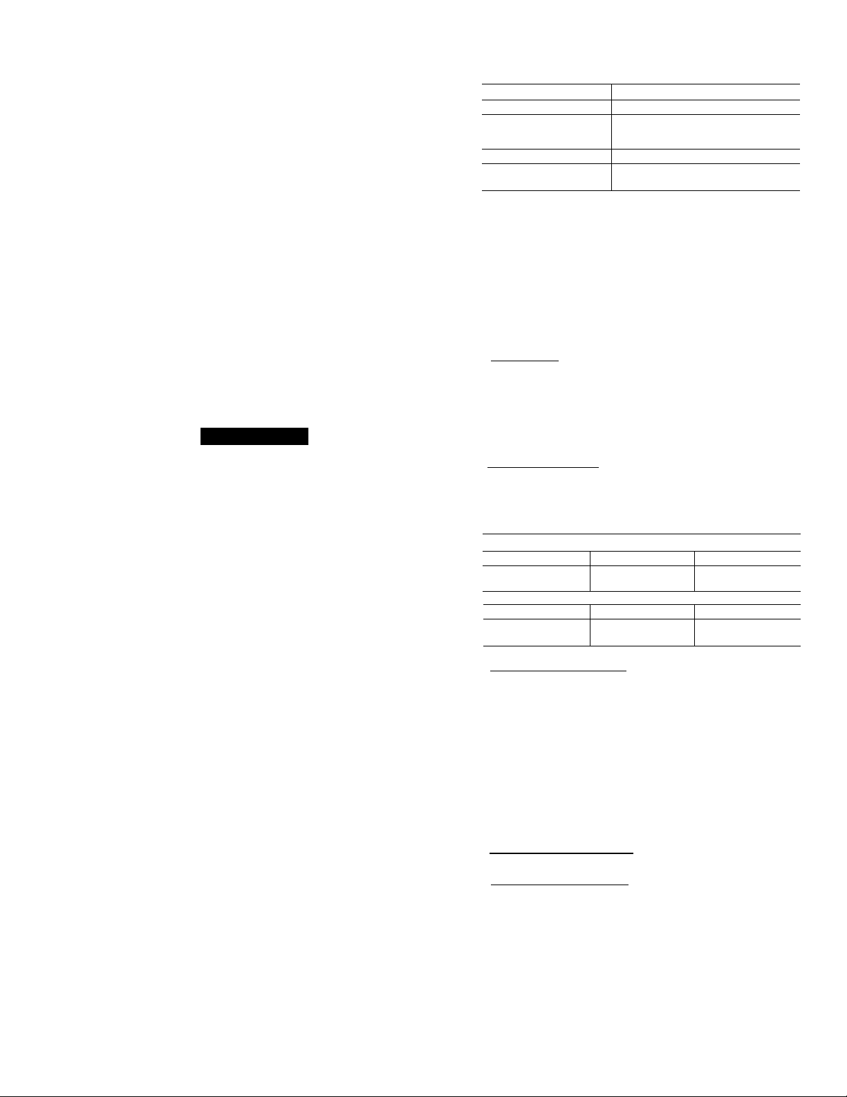
4. Maximum field wire sizes allowed by lugs on terminal
block are as follows:
V-PH-HZ
208/230-3-60
380-3-60
460-3-60
575-3-60
230-3-50
346-3-50
400-3-50
WIRE SIZE
350 kcmil (177.90 sq mm)
2/0 AWG (67 42 sq mm)
350 kcmil (177.90 sq mm)
2/0 AWG (67.42 sq mm)
5. Terminals for field power supply are suitable for cop
per, copper-clad aluminum, or aluminum conductors.
Insulation must be rated 167 F (75 C) minimum.
CONDENSER FANS — The fans must rotate counter
clockwise when viewed from above. If necessary, correct
direction of fan rotation by interchanging any 2 power
input wires at disconneet switch. Affix crankcase heater
decal (located in installer’s packet) to unit disconnect
switch.
FIELD CONNECTIONS
1. Main Power — Bring wires from the fused disconnect
switch through hole in bottom rail of unit to control box
(Fig. 6) and connect to terminals
11
13
12
on line side of terminal block TBl (see Fig. 7 or 8). To
comply with NEC Article 440-14, the disconnect must
be located within sight from and readily accessible from
the unit.
2.
24-v Control Power — Units have single point power
connections. Control circuit is directly connected inter
nally to unit. Maximum 24-v control circuit is 3.2 amps.
NOTE; For wire runs, use the following sizes of insu
lated wire;
Ft
0-50
No 18 AWG No 16 AWG No 14 AWG
35 C Min 35 C Min 35 C Min
0-15.2 15.2-22.9
0 82 sq mm 1.30 sq mm 2 08 sq mm
35 C Min 35 C Min 35 C Min
50-75
Over 75
Over 22.9
Power Wiring — All power wiring must comply with
applicable local and national codes. Install field-supplied
branch circuit fused disconnect(s) per NEC (National Eleetrical Code [U.S.A. Standard]) of a type that can be locked
OFF or OPEN. Disconnect(s) must be within sight from
and readily accessible from unit in compliance with NEC
Article 440-14.
GENERAL WIRING NOTES
1. A crankcase heater is wired in the eontrol cireuit so it is
always operable as long as power supply disconnect is
on, even if any safety device is open or unit stop-start
switch is off. It is protected by a 5-amp circuit breaker
in control power.
2. The power circuit field supply disconnect should never
be open except when unit is being serviced or is to be
down for a prolonged period. When operation is re
sumed, crankcase heater should be energized for 24 hours
before start-up. If unit is to be shut down for a pro
longed period, it is recommended that the suction and
discharge valves be closed to prevent an excessive ac
cumulation of refrigerant in the compressor oil.
3. Power entry is at compressor end only.
3. Control Circuit Interlock — An airflow switch may be
installed in the indoor air handler to prevent unit from
running when indoor air is not flowing. This switch
(Carrier part no. HR81JE001) is available from Service
Parts Center, or equivalent can be field supplied. This
should be electrically interlocked in the control circuit
as shown on the label diagram affixed to the access panel
on end of unit. Note that for a single air handler with
constant volume controls (those shown in Fig. 7 and 8),
the airflow switch must be used in combination with a
relay having 2 sets of normally open contacts (Carrier
part no. HN61KK040 or equivalent). For wiring, see
unit label diagram on inside of unit access door.
4. ModuPanel™ Connections — Refer to Fig. 9 and 10 for
field connections.
5. Transformer Connections — See unit wiring label diagram, notes 1 and 2, located behind compressor com
partment end access door.
IMPORTANT: Ensure power to the crankcase
heater is always on (except when servicing the
unit). If circuit breakers inside unit shut down
the compressor and condenser fans, crankcase heater
remains on.
Page 8
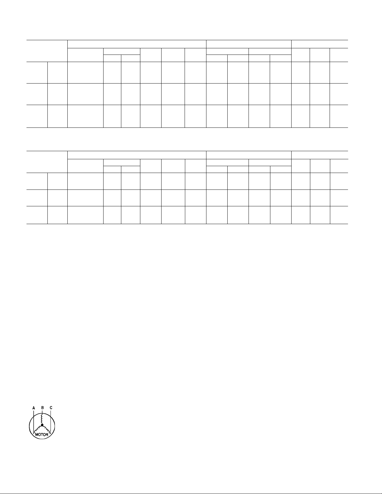
Table 3 — Electrical Data
60 HERTZ
UNIT 38AH
500
024
028
034
024 300 346
028
034
200
600
too
500
200
600 460
100 575
500
200
600
100
UNIT 38AH
800 230
900 400
800
300 346
900
800
300
900
Volts
3 Ph, 60 Hz
208/230
380
460
575
208/230
380
208/230
380
460
575
Volts
3 Ph, 50 Hz
230
400
230
346
400
UNIT COMPRESSOR
Supplied*
Min Max
187 254 100 8 125
342 418 61 8 80
414 508 50.3 60
632
518
254 110.5 150
187
342 418
414 508
632 47.1
518
254
187
342 418 77.0 110 256 8
414 508 65.8 90
632
518
MCA
42 1
135 5 175
MOCP
(Fuse)
50
67.2
55.9
53 3 70 193.8
90
70
60
ICF
408.4 39.3 39.3 198 198 2
193.8
204.2 196 196
168.4
468.4
215 8
234 2 22 1 22 1
188.8 19.7
506.4 43.6 63.6
340.2 22.1 30.0 114
50 HERTZ
UNIT COMPRESSOR
Supplied*
Min Max
254 101 2 125
198
311 380
342
400
198
311 380
342 400
198
311
342 400 65.1 90
MCA
254
254 135.9 175
380 78 1 110
1109 150
MOCP
(Fuse)
62.8 80 194.8 24 0
46.5 60 204 0 180
68.2
55.7
90
70
ICF
268.8 39.3 39.3
298 8 43.6
216.8
234 0
355 8 43.6 63 6 143
257.8 26.4 34.3 104 145 2 4.4 1
240 0 22 1 30 0 114
RLA LRA
Ckt 1
24 0
15.7
43.6
26 4 26 4
26.4 34 3 104
17.9 22 9
Ckt 1
26.4 26.4
22 1 22 1
Ckt 2 Cktl
24.0
157
43 6
19 7
RLA LRA
Ckt 2
24.0
18.0
43.6
Ckt 1 Ckt 2
FAN MOTORSt
Ckt 2
93 93
99 99
79 79
228 228
104 104
114 114
91
228 266
91 36
128 128
143 143 2
104 104 2
114 114 2 30
145
120
93 93
99 99
200
120
Qty
91
Qty
FLA
(ea)
6.2
2 39
2 3 1
2 3.4
2 62
2
39
2
3 1
3.4
2
2 62
2 39
2
3.1
2 34
FAN MOTORSt
FLA
(ea)
2 6.4
2 44 1
2
3.0
64
44 1
2 6.4
2 30
Hp
1
1
1
Hp
LEGEND
FLA — Full Load Amps
IGF — Maximum Instantaneous Current Flow during starting (the
LRA — Locked Rotor Amps
MCA — Minimum Circuit Amps (complies with National Electrical Code
MOCP — Maximum Overcurrent Protection
RLA — Rated Load Amps
point in the starting sequence where the sum of the LRA for
the starting compressor, plus the total RLA for all running com
pressors, plus the total FLA for all running fan motors is
maximum)
[NEC], Section 430-24) (U.S.A Standard)
UNBALANCED 3-PHASE SUPPLY VOLTAGE - Never
operate a motor where a phase imbalance in supply voltage
is greater than 2%. Use the following formula to determine
the percent voltage imbalance:
% Voltage Imbalance
— 100 max voltage deviation from average voltage
average voltage
Example: Supply voltage is 240-3-60.
AB = 243 V
BC =236 V
AC =238 V
Average Voltage =
243 -F236 -F238
= 239 V
’Units are suitable for use on electrical systems where volt
age supplied to unit terminals is not below or above listed
minimum and maximum limits
tAII fans are protected by a single circuit breaker.
Determine maximum deviation from average voltage:
(AB) 243 -239 =4 V
(BC) 239 -236 =3 V
(AC) 239 - 238 = 1 V
Maximum deviation is 4 v.
Determine percent voltage imbalance:
% Voltage Imbalance = 100 x
■ 1.1%
4
239
This amount of phase imbalance is satisfactory as it is
below the maximum allowable 2%.
IMPORTANT: Contact your local electric utility com
pany immediately if the supply voltage phase imbal
ance is more than 2%.
Page 9

CKTNO. 1
HINGED ACCESS DOOR
CKT NO 1COMPR
if''
FIELD CONTROL CIRCUIT WIRING
[22] 7/8' DIA (2)
CONTROL BOX
[22] 7/8 DIA
VAV CONTROL
[63-92] 2 l/2'-3 5/8 DIA
FIELD MAIN POWER SUPPLY
LEGEND
VAV — Variable Air Volume
NOTES;
1 There must be 4 ft [1220 mm] for ser
vice and for unrestricted airflow on all
sides of unit.
2 There must be 8 ft [2440 mm] clear
air space above unit
3. “C” is the package number indicates
copper coils
4 Dimensions in [ ] are in millimeters
5 The approximate operating weight of
the unit is shown below
6. Certified dimension drawing available
on request.
UNIT
38AH
024
024C
028
028C
034
034C
[63-92]
2 1/2"-3 5/8" DIA
FIELD POWER
ENTRY AND UFTING
CORNER WEIGHT - lbs [kg]
“1”
631.6
[286.5]
666 5
[302.3]
658.7
[298.8]
693.0
[314 3]
667 0
[302.5]
718 3
[325.8]
“2”
577.6
[262.0]
609 5
[276.5]
602.4
[273.3]
633 8
[287 5]
610 0
[276 7]
656.8
[297.9]
263 1
[119 3]
309.0
[140.2]
267 0
[121.1]
313.0
[142.0]
[130 7]
[156.4]
“3”
288.0
344.8
“4”
287.7
[130.5]
337 9
[153.3]
291 9
[132 4]
342 2
[155.2]
315.0
[142.9]
377.0
[171.0]
[22]
7/8' DIA (2)
FIELD CONTROL
POWER ENTRY
CENTER OF
GRAVITY^
A Dim.
in.
[mm]
40.0
[1016]
43.0
[1092]
39.3
[997]
42.3
[1073]
41 0
[1041]
44.0
[1117]
[22] 7/8 DIA
VAV
POWER ENTRY
B Dim.
in.
[mm]
32.8
[832]
TOTAL
UNIT
lb [kg]
1760
[798 3]
1923
[872.3]
1820
[825 6]
1982
[899 0]
1880
[853.0]
2097
[951.2]
10'-7 13/15'
SIDE VIEW
Fig. 6 — Dimensional Drawing — Units 38AH024, 028, 034
Page 10

3-WIRE COM BUS
! TO OTHER COMMUNICATING
f THERMOSTATS
0 o o o o o
1 2 1 2 FAN R.V.
COOL HEAT
TSR-01 RELAY PACK (MAXIMUM CONTACT
LOAD IS 1 AMP AT 24 V) (SEE NOTE 3.)
LEGEND
AUTO
C
CB
COM
GND
IFC
LLS
NEC
R.V.
TB
TC
Automatic Changeover
Contactor, Compressor
Circuit Breaker
Common
Ground
Indoor-Fan Contactor
Liquid Line Solenoid
National Electrical Code
(U.S.A. Standard)
Reversing Valve
Terminal Block
Thermostat, Cooling
Field Accessory Wiring
Field Control Wiring
Factory Wiring
Field Power Wiring
Indicates Common Potential;
Does Not Indicate Wiring
CARRIER COMMUNICATING
TEMP MONITOR
THERMOSTAT
(MODEL MS(T)OIES)
HEAT 2
HEAT1
COOL 2
COOL1
24 VAC (COMMON)
24 VAC (R)
THERMOSTAT*
o[^o[^o[^
CB5
24 V
TB2
[H
[C]
—
--[yT]
r
S
ra
—
-d]
—
--d]
--En]
S 1 ll
~Cr]
CB4
24 V
CB3
115 V t (ON 380-V UNITS. TB IS 230 V)
(346, 380,
400 V ONLY)
TB3
Illsi 1-
ICOMh
IlFClh
fCOMh
1 as2|--
ICOMh
1IFC2 1
ICOMi
1 1'
“1
11
1
'
( 1
ll
J_L,
■“I
_
“I
I
___
1
LLS1 (24 V)*
*Use thermostat wiring shown here for single air-handler
applications.
tCB3 protects control circuit at the following unit voltages:
CONTROL CIRCUIT
PROTECTED AT:
(V-Ph-Hz)
115-1-60
230-1-60
230-1-50
**For a single air handler, LLS valve no. 1 is to be used on the lower
(no. 1) evaporator circuit. The LLS valve no. 2 is to be used on the
upper (no. 2) evaportor circuit.
ttOnly one indoor-fan contactor is required on single air-handler
applications. Use Carrier accessory part no. 40RR900181 for indoor-
fan confacfor.
UNIT (V-Ph-Hz)
208/230-3-60
460-3-60
575-3-60
380-3-60
230-3-50
346-3-50
400-3-50
NOTES:
1. CB4 protects TB3 circuit; CBS protects TB2 circuits.
2. LLS1 and LLS2 are field supplied.
3. TB2 and TB3 are in 24-v circuits.
4. On the TSR-01 Relay Pack, the outside-air sensor, supply-air
sensor, and direct expansion coil sensor are available as
options.
Fig. 7 — Typical Wiring Schematic — Unit 38AH with Single Air Handler
I
Iz^j-i
TB1
ELD POWER SUPPLY
NEC DISCONNECT J
2 1/2” (63 mm) DIA HOLE
3 5/8" (92 mm) DIA HOLE
OR
Page 11

TSR-01 RELAY PACK (MAXIMUM CONTACT
LOAD IS 1 AMP AT 24 V) (SEE NOTE 3.)
TO OTHER COMMUNICATING
THERMOSTATS
CARRIER COMMUNICATING
TEMP MONITOR
THERMOSTAT
{MODEL MS(T)OIES)
FAN
HEAT 2
-----
HEAT1
------
COOL 2
8 0 COOL 1
1 |I®1 24 VAC
^111^—24 VAC —
----------
------------------
24 VAC — —
(COMMON)
FAN
-------
HEAT 2 —
HEAT1 —
COOL2 -
COOL1- -
(COMMON)
1
*CB3 protects control circuit at the following unit voltages;
THERMOSTAT NO. 1
CONTROL CIRCUIT
PROTECTED AT:
(V-Ph-Hz)
115-1-60 460-3-60
230-1-60 380-3-60
230-1-50
UNIT (V-Ph-Hz)
208/230-3-60
575-3-60
230-3-50
346-3-50
400-3-50
fuse Carrier accessory part no. 40RR900181 for indoor-
fan contactor.
"Install LLS valve no. 1 on the liquid line of the air handler
controlled by the 38AH circuit no. 1 thermostat. Install
LLS valve no. 2 on the liquid line of the air handler con
trolled by the 38AH circuit no. 2 thermostat.
NOTES:
1. Capacity control solenoid and liquid line (solenoid drop
refrigerant control) valves are field supplied.
2. CB4 protects TBS circuit; CBS protects TB2 circuit.
3. On the TSR-01 Relay Pack, the outside-air sensor, supplyair sensor, and direct expansion coll sensor are avail
able as options.
TSR-01 RELAY PACK (MAXIMUM CONTACT
LOAD IS 1 AMP AT 24 V) (SEE NOTE 3.)
3-WIRE COM BUS
TO OTHER COMMUNICATING
THERMOSTATS
CARRIER COMMUNICATING
TEMP MONITOR
THERMOSTAT
(MODEL MS(T)OIES)
Fig. 8 — Typical Wiring Schematic — Unit 38AH with 2 Air Handlers
R.V.
TB
Automatic Changeover
LEGEND
Contactor, Compressor
Circuit Breaker
Capacity Control Solenoid
Common
Ground
Indoor-Fan Contactor
Liquid Line Solenoid
National Electrical Code
^.S.A. Standard)
Reversing Valve
Terminal Block
Thermostat, Cooling
Field Accessory Wiring
Field Control Wiring
Factory Wiring
Field Power Wiring
Indicates Common
Potential; Does Not
Indicate Wiring
Page 12

LLSV CONTROL SCHEMATIC 124 VI
AFS — Airflow Switch LLSV
C — Contactor, Compressor LOR
CB — Circuit Breaker LPS
CLO — Compressor Lock-Out OPS
COM — Common PL
COTP — Compressor Overcurrent Protection SOLR
CR — Control Relay STAT
DISC — Disconnect TB
HPS — High-Pressure Switch TGD
IPC — Indoor-Fan Contactor TRAN
IPR — Indoor-Fan Relay U
kcmil — thousand circular mils VA
LLS — Liquid Line Solenoid VAV
NOTES TO FIG. 9 AND 10
Factory wiring is in accordance with National Electrical Code (NEC)
(U.S A. Standard) Field modifications or additions must be in com
pliance with all applicable codes
Wiring for field power supply must be rated 75 C minimum. Use
copper, copper-clad aluminum, or aluminum conductors Maxi
mum incoming wire size for main terminal block (TB1) is 350 max
kcmil (230 v). All other voltages 2/0 AWG (American Wire Gage)
maximum
Terminal blocks TB2, TB3, and TB4 are for external field control
connections Control connections are to be class 2 wiring.
Field-supplied components connected to TB3 (e.g., LLS1 and
LLS2) cannot exceed 75 va total inductive load at 24 vac, so that
Fig. 9 — Typical Wiring Schematic — VAV ModuPaner
One Dual-Circuit Condensing Unit with Air Handler
LEGEND
Liquid Line Solenoid Valve
Lock-Out Relay
Low-Pressure Switch
Oil Pressure Switch
Plug Assembly
Solenoid Relay
Thermostat
Terminal Block
Time Guard® Device
Transformer
Unloader (Solenoid)
Volt-Ampere
Variable Air Volume
TRAN1 does not become overloaded The air handler auxiliary
motor starter contacts must have a minimum rating of 30 va at
24 vac The airflow switch must have minimum contact rating of
125 va at 24 vac.
5. Replacement of factory wires must be with type 105 C wire or its
equivalent
6. Field-supplied liquid line solenoid valves installed at the evapo
rator are required on circuits no. 1 and 2 on all units
7. ModuPanel control is wired for one air handler only Re
move wire between TB2-2 to TB2-7 for ModuPanel control
applications
12
I I Terminal Block Connection
^—> Marked Terminal
Unmarked Terminal
O
Unmarked Splice
Field Accessory Wiring
Factory Wiring
Field Control Wiring
Field Power Wiring
Indicates Common Potential;
Does Not Represent Wiring
Page 13

( "
AFR
AFS
C
CB
CLO
COM
COTP
CR
DISC
HPS
IPC
IPR
kcmil
LLS
___
Airflow Relay
—
Airflow Switch
—
Contactor, Compressor
—
Circuit Breaker
—
Compressor Lock-Cut
—
Common
—
Compressor Cvercurrent Protection
—
Control Relay
—
Disconnect
—
High-Pressure Switch
—
Indoor-Fan Contactor
—
Indoor-Fan Relay
___
thousand circular mils
Liquid Line Solenoid
-
—
LLSV
LOR
LPS
OPS —
PL
SOLR
STAT
TB
TGD
TRAN
U
VA
VAV
Liquid Line Soienoid Valve I I
Lock-Out Reiay
—
Low-Pressure Switch ^ >
—
Oii Pressure Switch
Plug Assembly O
—
Solenoid Relay
—
Thermostat
—
Terminal Block
—
Time Guard® Device
—
Transformer
—
Unloader (Solenoid)
—
Volt-Ampere
—
Variable Air Volume
—
---------
__
______
______
______
Fig. 10 — Typical Wiring Schematic — VAV ModuPaner
Two Dual-Circuit Condensing Units
with Air Handler
13
Terminal Block Connection
Marked Terminal
Unmarked Terminal
^
Unmarked Splice
Field Accessory Wiring
Factory Wiring
Field Control Wiring
Field Power Wiring
Indicates Common Potential,
Does Not Represent Wiring
Page 14

PRE-START-UP
IMPORTANT: Before beginning Pre-Start-Up or
Start-Up, review Start-Up Checklist at the back of this
book. The Checklist assures proper start-up of a unit
and provides a record of unit condition, application
requirements, system information, and operation at ini
tial start-up.
A CAUTION
Do not attempt to start the condensing unit, even
momentarily, until the following steps have been com
pleted. Compressor damage may result.
System Check
1. Check all air handler(s) and other equipment auxiliary
components. Consult the manufacturer’s instructions re
garding any other equipment connected to the condens
ing unit. If unit has field-installed accessories, be sure
all are properly installed and correctly wired. If used,
airflow switch must be properly installed. See Fig. 9
or 10.
2. Backseat (open) compressor suction and discharge valves.
Now close valves one turn to allow refrigerant pressure
to reach test gages.
3. Open liquid line service valves.
4. Check tightness of all electrical connections.
5. Compressor oil level should be visible in sight glass.
Adjust the oil level as required. No oil should be
removed unless the crankcase heater has been ener
gized for at least 24 hours. See Service section. Oil
Charge on page 18.
6. Be sure unit is properly leak checked, dehydrated, and
charged. See Preliminary Charge, below.
7. Electrical power source must agree with nameplate
rating.
8. Crankcase heater must be firmly locked into compres
sor crankcase. Be sure crankcase is warm (heater must
be on for 24 hours before starting compressor).
9. Fan motors are 3-phase. Check rotation of fans during
first start-up check. Fan rotation is counterclockwise
as viewed from top of unit. If fan is not turning
counterclockwise, reverse 2 of the power wires.
10. Be sure compressor floats freely on the mounting springs
and that snubber washers can be moved with finger pres
sure. See Compressor Mounting, page 5, and Fig. 3
for loosening compressor bolts.
Leak Test and Dehydration — Leak test the entire
refrigerant system using soap bubbles and/or an electric
leak detector. Evacuate and dehydrate entire refrigerant sys
tem by use of methods described in GTAC II, Module 4,
System Dehydration.
Preliminary Charge — Refer to GTAC II, Module 5,
Charging, Recovery, Recycling, and Reclamation for charg
ing methods and procedures. Charge each system with R-22
by the liquid charging method (through liquid service valve)
on the high side. See approximate refrigerant charge in
Table 1A or IB. Charge according to the values in the Charg
ing Chart, Eig. 11, page 16.
START-UP
Compressor crankcase heaters must be on for 24 hours
before start-up. To energize the crankcase heaters, set the
space thermostat above the ambient so there will be no de
mand for cooling. Close the field disconnect and turn on
the fan circuit breakers. Leave the compressor circuit break
ers off/open. The crankcase heaters are now energized.
After the heater has been on for 24 hours, the unit can be
started. If no time has elapsed since the preliminary charge
step has been completed, it is unnecessary to wait the
24-hour period.
Preliminary Checks
1. Ensure that compressor service valves are backseated.
2. Verify that each compressor floats freely on its mount
ing springs.
3. Check that electric power supply agrees with unit name
plate data.
4. Verify that compressor crankcase heaters are securely in
place.
5. Check that compressor crankcase heaters have been on
at least 24 hours.
6. Note that compressor oil level is visible in the sight glass.
7. Recheck for leaks using same procedure as previously
outlined in Pre-Start-Up section. Leak Test and De
hydration, this page.
8. If any leads are detected, evacuate and dehydrate as pre
viously outlined in Pre-Start-Up section. Leak Test and
Dehydration, this page.
Preliminary Oil Charge — Each compressor is fac
tory charged with oil (see Table lA or IB). When oil is
checked at start-up, it may be necessary to add or remove
oil to bring it to the proper level. One recommended oil
level adjustment method is as follows:
ADD OIL — Close suction service valve and pump down
crankcase to 2 psig (14 kPa). (Low-pressure switch must be
jumpered.) Wait a few minutes and repeat until pressure re
mains steady at 2 psig (14 kPa). Remove oil fill plug above
the bull’s-eye, add oil through plug hole, and replace plug.
Run compressor for 20 minutes and check oil level.
NOTE: Use only Carrier approved compressor oil. Ap
proved sources are:
Petroleum Specialties Inc
Texaco, Inc......................................................Capella WF-32
Witco Chemical Co...............................................Suniso 3GS
Do not use oil that has been drained out, or oil that has
been exposed to atmosphere.
REMOVE OIL — Pump down compressor to 2 psig
(14 kPag). Loosen the Ut-in. (6.4 mm) pipe plug at the com
pressor base and allow the oil to seep out past the threads
of the plug.
NOTE: The crankcase will be slightly pressurized. Do not
remove the plug, or the entire oil charge will be lost.
Small amounts of oil can be removed through the oil pump
discharge connection while the compressor is running.
.....................................
Cryol 150A
Start Unit — The field disconnect is closed, the fan cir
cuit breaker is closed and the space thermostats are set above
ambient so that there is no demand for cooling. Only the
crankcase heaters will be energized.
i
14
Page 15

Next, close the compressor circuit breakers and then re
set space thermostat TCI below ambient so that a call for
stage one cooling is ensured. If compressor does not start,
set thermostat lower.
NOTE: Do not use circuit breakers to start and stop the
compressor except in an emergency.
If 38AH is connected to a single 2-stage cooling thermo
stat (one fan coil), start-up of circuit no. 1 compressor will
be delayed from one second to 5 minutes from the time the
call for cooling is initiated (see Fig. 12). TC2 (thermostat
contacts 2) close l'/2° F (0.7° C) lower than TCI. After
these contacts close, start up of circuit no. 2 compressor
will be delayed from one second to 5 minutes from the time
the call for cooling is initiated (see Fig. 12).
A CAUTION
Never charge liquid into the low-pressure side of sys
tem. Do not overcharge. During charging or removal
of refrigerant, be sure indoor-fan system is operating.
Adjust Refrigerant Charge
NOTE: Actual start-up and all refrigerant charge modifica
tions should be done only under supervision of a qualified
refrigeration mechanic.
With all fans operating, adjust the refrigerant charge in ac
cordance with the unit charging charts located on the inside
of the control box doors and in Fig. 11.
Measure pressure at the liquid line service valve, being
sure Schrader depressor is used if required. Also, measure
liquid line temperature as close to the liquid service valve
as possible. Add charge until the pressure and temperature
conditions of the charging chart curve are met. If liquid
pressure and temperature point fall above curve, add charge.
If liquid pressure and temperature point fall below curve,
reduce the charge until the conditions match the curve.
If the sight glass is cloudy, check refrigerant charge again.
Ensure all fans are operating. Also ensure maximum
allowable liquid lift has not been exceeded. If charged per
chart and if the sight glass is still cloudy, check for a plugged
filter drier or a partially closed solenoid valve. Replace or
repair, as needed.
Check Compressor Oil Level — After adjusting the
refrigerant charge, allow each circuit to run fully loaded for
20 minutes. Running oil level should be within view of the
crankcase sight glass. Stop the compressors at the field power
supply disconnect and check the crankcase oil level. Add
oil only if necessary to bring the oil into view in the sight
glass. If oil is added, run the circuit for an additional 10
minutes, then stop and check oil level. If the level remains
low, check the piping system for proper design for oil re
turn; also, check the system for leaks.
If the initial check shows too much oil (too high in the
sight glass) remove oil to proper level. See Preliminary Oil
Charge, page 14, for proper procedure for adding and re
moving oil.
When the above checks are complete, repeat the proce
dure with the unit operating at minimum load conditions.
For this minimum load check, operate each circuit’s com
pressor individually and unloaded to minimum step.
Unload the compressor(s) by turning the control set point
adjustment nut counterclockwise until the adjustment nut
stops. The unloader is now at 0 psig (0 kPag) set point. If
electric actuated unloaders are installed, energize the sole
noid to unload the compressor.
Return unloader to original setting after checks are
complete.
Final Checks — Ensure all safety controls are operat
ing, control panel covers are on, and the service panels are
in place.
15
Page 16

500
500 1000 1500 2000 2500
NOTE: All outdoor fans must be operating
Fig. 11 - Units 38AH024-034 Charging Chart, 50/60 Hz (Circuits No. 1 and 2)
1000 1500 2000
LIQUID PRESSURE AT LIQUID VALVE (kPag)
UNITS 38AH024 AND 028
LIQUID PRESSURE AT LIQUID VALVE (kPag)
UNIT 38AH034
2500
TIME DELAY TIMING SEQUENCE
U
---------------— 1 SEC
1 V///////////////////22Z.
TIME GUARD® I
RUNNING TIME
--------------------------------------
----------------
DEVICE (CIRCUITS NO 1 AND 2)
—
-180 SEC-
DENOTES CLOSED CONTACTS
--------------------
RUNNING TIME
ACCESSORY WINTER-START KIT
(CARRIER PART NO. 38AE900021)
Fig. 12 — Timer Sequence Chart
16
►
5 MIN
---------
Page 17

SEQUENCE OF OPERATION
Single Air Handler, 2-Stage Cool Thermostat
— At start-up, the thermostat calls for first-stage cooling
(TCI closes) and with all safety devices satisfied, circuit
no. 1 control relay (CRl) closes, deenergizing the crank
case heater at compressor no. 1. The indoor-fan motor starts
immediately, and the liquid line solenoid valve (LLSV) for
solenoid drop refrigeration control on circuit no. 1 opens.
Outdoor-fan motor no.l and compressor no. 1 start after
one second. Fan no. 2 starts if the outdoor ambient is above
60 F (15.6 C).
On standard units, compressor no. 1 operates either fully
loaded or at one step of unloading depending on the suction
pressure, which in turn is dependent on the evaporator load
conditions. As cooling demand increases, TC2 of the 2-stage
thermostat energizes control relay no. 2. CR2 deenergizes
the crankcase heater at compressor no. 2 and brings on com
pressor no. 2 after one second. The LLSV for solenoid drop
refrigerant control (circuit no. 2) opens as soon as CR2 is
energized. On standard units, compressor no. 2 operates
fully loaded.
As cooling demand is satisfied, thermostat contacts TC2
break and deenergize CR2 which then deenergizes compres
sor no. 2 and energizes its crankcase heater. The LLSV on
circuit no. 2 closes, preventing refrigerant migration back
to compressor no. 2 during the off cycle. If the space tem
perature continues to decrease, stage 1 thermostat contacts
TCI break and deenergize CRl. Immediately after CRl is
deenergized, compressor no. 1 shuts off and its crankcase
heater is energized. The LLSV on circuit no. 1 closes, pre
venting refrigerant migration back to compressor no. 1
during the off cycle. Outdoor-fan motors no. 1 and 2 de
energize as soon as CRl is deenergized.
NOTE: If thermostat fan switch is in the auto position, the
indoor fan will cycle on and off as the thermostat calls for
cooling (or heating). If the fan switch is in the continuous
position, the fan will run as long as the outdoor unit is pow
ered up.
Two Air Handlers — Two 2-Stage Cool Ther
mostats (One Per Air Handler) — At start-up of
circuit no. 1, the thermostat controlling circuit no. 1 calls
for first stage of cooling when thermostat contact TCI closes.
If all safety devices are satisfied, circuit no. 1 control relay
CRl energizes which deenergizes the crankcase heater in
side compressor no. 1. The indoor-fan motor on the circuit
no. 1 fan coil starts immediately, and the main liquid line
solenoid valve (LLSV) for solenoid drop refrigerant control
on circuit no. 1 opens. Outdoor-fan motor no. 1 and com
pressor no. 1 start after one second. Fan no. 2 starts if the
outdoor ambient is above 60 F (15.6 C).
On standard units, compressor no. 1 operates either fully
loaded or at one step of unloading depending on the suction
pressure, which in turn is dependent on the evaporator load
conditions. As cooling demand increases, TC2 of the 2-stage
thermostat energizes the capacity control LLSV resulting in
full activity of the evaporator surface. The fully active
evaporator surface will raise the suction pressure until the
pressure-operated capacity control valve setting is ex
ceeded, so that the compressor becomes fully loaded.
The thermostat controlling circuit no. 2 calls for first stage
of cooling when thermostat contact TC2 closes. Assuming
all safety devices are satisfied, circuit no.2 control relay
CR2 energizes, which deenergizes the crankcase heater in
side compressor no. 2. The indoor-fan motor on circuit
no. 2 fan coil starts immediately, and the main LLSV for
solenoid drop refrigerant control on circuit no. 2 opens. Com
pressor no. 2 starts after one second. The outdoor fans are
already running if circuit no. 1 is running. If circuit no. 1 is
not running when thermostat no. 2 calls for cooling, the
outdoor fans are off. In this situation, outdoor-fan motor
no. 1 starts when compressor no. 2 starts. Outdoor-fan mo
tor no. 2 comes on if the outdoor ambient is above 60 F
(15.6 C).
As cooling demand is satisfied at thermostat no. 1 or 2
(whichever comes first), contacts TC2 break, and the ca
pacity control LLSV on that circuit is deenergized. This
prevents refrigerant flow through the upper (circpit no. 1 or
2) evaporator section causing the suction pressure to drop
and the compressor on that circuit to unload.
NOTE; Circuit no. 2 does not have a factory-installed un
loader. If desired, one must be added in the field.
As the space temperature drops further, the space ther
mostat contacts TCI open which will deenergize control re
lay CRl or CR2. Immediately after CRl or CR2 is deen
ergized, the compressor CRl or CR2 control is shut off and
its crankcase heater is energized. The LLSV on that circuit
closes, preventing refrigeration migration back to the com
pressor during the off cycle. Outdoor-fan motors no. 1 and
2 are deenergized only if the space thermostats for both cir
cuits no. 1 and 2 are not calling for cooling.
NOTE; If thermostat fan switch is in the auto position, the
indoor fan will cycle on and off as the thermostat calls for
cooling (or heating). If the fan switch is in the continuous
position, the fan will run as long as the outdoor unit is pow
ered up.
Restart — Manual reset of the 24-v control circuit is nec
essary if unit shutdown is caused by automatic reset de
vices (including COTP [compressor overcurrent protection]
and HPS [high-pressure switch]) or if shutdown is caused
by manual reset devices (including OPS [oil pressure switch]
and compressor circuit breaker protection). To restart the
unit when COTP or HPS has tripped {after COTP and HPS
have reset automatically), open and then close the thermo
stat contacts. Opening and then closing thermostat contacts
interrupt and reapply 24-v power to the compressor lockout
(CLOl and CL02) which resets the devices.
It is necessary to manually reset the compressor circuit
breaker and OPS at the unit if either of these safeties should
shut down the unit.
IMPORTANT: If either OPS trips, it must be reset
first before making and breaking the thermostat con
tacts to reset CLOl and CL02. If this procedure is
not followed, the CLOl and CL02 cannot reset.
If the LPS (low-pressure switch) is not closed, the call
for cooling is interrupted and the Time Guard® device is
activated. This deenergizes control relay(s) (CRl or CR2)
and deenergizes the compressor for a 5-minute time period.
At the end of this 5-minute period, if the LPS is closed, the
compressor restarts. If the system is low on charge, LPS
cannot reset and the unit will stay off on this safety.
Causes of Complete Unit Shutdown:
• interruption of supplied power
• open compressor overtemperature protection (COTP)
• compressor electrical overload protection (CB1 or CB2)
• open high-pressure or low-pressure safety switches
• open oil pressure switch
17
Page 18

SERVICE
A CAUTION
I Tum off all power to unit before proceeding.
Access for Servicing (See Fig. 13)
COMPRESSOR SECTION — The compressor compart
ment has 2 side doors and one front door for servicing, pro
viding access to compressors, all components of the refrig
eration system, electrical controls, and control box. After
opening the front door an inner cover must be removed for
access to control box.
OIL PRESSURE SAFETY SWITCH - Switch is reset by
opening either access door on either side of the unit. Circuit
no. 1 oil pressure safety switch is reset by opening the side
access door on the left side of the unit (as viewed from the
compressor end). Circuit no. 2 oil pressure safety switch is
reset by opening the side access door on the right side of
the unit. Circuit no. 1 liquid line service valve is located
directly below circuit no. 1 oil pressure switch. Circuit
no. 2 liquid line service valve is located directly below cir
cuit no. 2 oil pressure switch.
CONDENSER SECTION — Condenser-fan motors and fans
can be serviced by removal of outlet grilles or side panels.
If a fan motor is serviced, be sure the wire fan guard is in
place over each fan before starting unit. See Fig. 14 for
proper fan adjustment. Tighten fan hub securely on motor
shaft with setscrew which bears against the key. Be sure to
replace Permagum and rubber cap over end of motor shaft
to protect against moisture causing fan to rust on shaft. Re
check rotation of fan(s) after service work on motors.
Fan Adjustment (See Fig. 14)
Oil Charge — Compressors are factory charged with oil
as follows:
COMPRESSOR
06D824
06D328
06D537
When additional oil or a complete charge is required, use
only Carrier-approved compressor oil:
Petroleum Specialities
Texaco, Inc......................................................Capella WF-32
Witco Chemical Corp
IMPORTANT: Do not use drained oil or use oil that
has been exposed to atmosphere. Refer to GTAC II,
Module 5; Charging, Recovery, Recycling, and Rec
lamation for procedures to add oil. To remove excess
oil. Isolate the compressor by use of the service valves,
slowly relieve the internal pressure, and then use the
oil drain plug at the bottom of the compressor to re
move the excess oil.
..........................................
..........................................
AMOUNT
pints (liters)
10 (4.73)
10 (4.73)
10 (4.73)
________
Cryol 150A
Suniso 3GS
CONTROL SET POINT — The control set point (cylin
der load point) is adjustable from 0 to 85 psig (0 to
586 kPa). To adjust, turn control set point adjustment nut
(Fig. 15) clockwise to its bottom stop. In this position,
set point is 85 psig (0 to 586 kPa). Then tum adjustment
counterclockwise to desired control set point. Every full
turn counterclockwise decreases set point by 7.5 psig
(51.7 kPa).
PRESSURE DIFFERENTIAL - The pressure differential
(difference between cylinder load and unload points) is ad
justable from 6 to 22 psig (41 to 15.2 kPa). To adjust, tum
pressure differential adjustment screw (Fig. 15) counter
clockwise to its backstop position. In this position, differ
ential is 6 psig (41 kPa). Then, tum adjustment clockwise
to desired pressure differential. Every full turn clockwise
increases differential by 1.5 psig. (10.34 kPa).
Capacity Control, Electrically Operated Unload
ers (Variable Air Volume, Factory-Installed
Option Units) — Each controls 2 cylinders. Electric
unloaders are not field adjustable. Circuit no. 1 compressor
on this factoiy-installed option has 2 electric unloaders. For
service, replace any failed solenoid.
Oil Pressure Safety Switch (OPS) — In the con
trol circuit, switch stops the compressor and unit, if proper
oil pressure differential is not established at start-up or main
tained during operation. If OPS stops the unit, determine
the cause and correct before restarting unit. Failure to do so
will constitute abuse. Equipment failure due to abuse may
void the warranty.
Compressor Protection
CIRCUIT BREAKER — Calibrated trip manual reset, am
bient compensated, magnetic breaker protects against
motor overload and locked rotor conditions.
COMPRESSOR OVERTEMPERATURE PROTECTION
(COTP) — A thermostat installed on compressor motor wind
ing reacts to excessively high winding temperatures and shuts
off the compressor.
TIME GUARD® Control — Control prevents compressor
from short cycling. See Sequence of Operation.
CRANKCASE HEATERS — Heaters minimize absorption
of liquid refrigerant by oil in crankcase during brief or ex
tended shutdown periods. The control circuit is maintained
if compressor fan motor circuit breakers are turned off. The
main disconnect must be on to energize crankcase heater.
IMPORTANT: Never open any switch or disconnect
that deenergizes the crankcase heaters unless unit is
being serviced or is to be shut down for a prolonged
period. After a prolonged shutdown on a service job,
energize the crankcase heaters for 24 hours before start
ing the compressor.
High-Pressure Switches — Switches have fixed,
nonadjustable settings. Switches are mounted on the
compressors.
Liquid Shutoff/Charging Valve — Valve is lo
cated inside the compressor compartment and is provided
with Vi-in. flare connection for field charging.
Capacity Control, Suction Pressure — Actu
ated Unloaders — Each controls 2 cylinders. Unload
ers are factory set (see Table lA or IB) but may be field
adjusted.
Low-Pressure Switches — Switches have fixed, non
adjustable settings. The switches are mounted on the
compressors.
TO CHECK — Slowly close liquid shutoff valve and allow
compressor to pump down. Do not allow compressor pump
down below 2 psig (13.8 kPa). Compressor should shut down
when suction pressure drops to cutout pressure in Table 4,
and should restart when pressure builds up to cut-in pres
sure shown.
18
Page 19

06D COMPRESSOR WITH PAN
OIL PRESSURE SWITCH AND LIQUID LINE SERVICE
VALVE LOCATIONS
CIRCUIT NO 1 CIRCUIT NO. 2
Fig. 13 — 38AH Unit with Access Panels Removed
19
Page 20

TOP OF FAN ORIFICE
FILL HOLE IN FAN HUB
CONTROL
SET POINT
ADJUSTMENT
-NUT
PROP LOCATION
60 Hz
38AH024-034
50 Hz
38AH024-034
“A” in. (mm)
3.5 (89)
4.3 (109)
Fig. 14 — Location of Prop on Motor Shaft
from Outside of Orifice Ring
Table 4 — Pressure Switch Settings, psig (kPa)
HIGH PRESSURE
Cutout Cut-in Cutout
426 ± 7 320 ± 20
(2937 ± 48) (2206 ± 138) 186 ± 21) (303 ± 34)
LOW PRESSURE
Cut-in
27 ± 3 44 ± 5
Winter Start Control — Purchase accessory Carrier
part no. 38AE900021 for winter start control.
Head Pressure Control — Control allows system to
operate at full capacity under low ambient temperature
conditions.
FAN CYCLING — These 38AH units have standard pro
vision for fully automatic intermediate-season head pres
sure control through condenser fan cycling. Fan no. 2 is
cycled by an outdoor-air thermostat which responds to out
door ambient temperature. The thermostat is loeated in the
PRESSURE
DIFFERENTIAL
ADJUSTMENT
SCREW
BYPASS
PISTON RING
BYPASS PISTON
DIFFERENTIAL SCREW
SEALING CAP
(CAP MUST BE REPLACED
TO PREVENT REFRIGERANT LEAKAGE)
POWER HEAD
VALVE BODY
Fig. 15 — Capacity Control Valve
lower divider panel between the compressor compartment
and condenser section. Through a hole in the panel, the
sensing element is exposed to air entering the no. 1 fan
compartment. Fan no. 1 is non-cycling. Table 5 shows the
operating settings of the air temperature switch.
Table 5 — Fan Cycling Controls
CONTROL BY
Temp — F (C)
NOTE: See Fig. 6 for fan arrangement.
SWITCH OPENS
60 ± 3 (15 6 ± 1.7) 70 ± 3 (21.1 ± 1.7)
SWITCH CLOSES
20
Page 21

TROUBLESHOOTING
PROBLEM
COMPRESSOR DOES NOT RUN
Contactor Open
1. Power off.
2. Fuses blown in field power circuit.
3. No control power.
4. Thermostat circuit open.
5. Time Guard® II device not operating.
6. Compressor circuit breaker tripped.
7. Safety device lock-out circuit active.
8. Oil pressure switch tripped.
9. See oil pressure switch section.
10. High-pressure switch open.
11. Compressor overtemperature switch open.
12. Loose electrical connections.
13. Compressor stuck.
Contactor Closed
1. Compressor leads loose.
2. Motor windings open.
3. Single phasing.
COMPRESSOR STOPS ON HIGH-PRESSURE
SWITCH
Outdoor Fan On
1. High-pressure switch faulty.
2. Reversed fan rotation.
3. Airflow restricted.
4. Air recirculating.
5. Noncondensables in system.
6. Refrigerant overcharge.
7. Line voltage incorrect.
8. Refrigerant system restrictions.
Outdoor Fan Off
1. Fan slips on shaft.
2. Motor not running.
3. Motor bearings stuck.
4. Motor overload open.
5. Motor burned out.
COMPRESSOR CYCLES ON LOW-PRESSURE
SWITCH
Indoor-Air Fan Running
1. Compressor suction service valve partially
closed.
2. Liquid line solenoid valve(s) fails to open.
3. Filter drier plugged.
4. Expansion valve power head defective.
5. Low refrigerant charge.
SOLUTION
1. Restore power.
2. After finding cause and correcting, replace with correct size
fuse.
3. Check secondary fuse(s); replace with correct type and size.
Replace transformer if primary windings receiving power.
4. Check thermostat setting.
5. Check Time Guard 11 devices.
6. Check for excessive compressor current draw. Reset breaker;
replace if defective.
7. Reset lock-out circuit at thermostat or circuit breaker.
8. See oil pressure switch section.
9. Check for refrigerant undercharge, obstruction of indoor air-
flow, or whether compressor suction shutoff valve is fully open.
Make sure liquid line solenoid valve(s) is open.
10. Check for refrigerant overcharge, obstruction of outdoor airflow, air in system, or whether compressor discharge valve is
fully open. Be sure outdoor fans are operating correctly.
11. Check for open condition. Allow for reset. Replace if defective.
12. Tighten all connections.
13. See 06D compressor service literature.
1. Check connections.
2. See 06D compressor service literature.
3. Check for blown fuse. Check for loose connection at compres-
sor terminal.
1. Replace switch.
2. Confirm rotation, correct if necessary.
3. Remove obstruction.
4. Clear airflow area.
5. Purge and recharge as required.
6. Purge as required.
7. Consult power company.
8. Check or replace filter drier, expansion valve, etc. Check that
compressor discharge service valve is fully open.
1. Tighten fan hub setscrews.
2. Check power and capacitor.
3. Replace bearings.
4. Check overload rating. Check for fan blade obstruction.
5. Replace motor.
1. Open valve fully.
2. Check liquid line solenoid valve(s) for proper operation.
Replace if necessary.
3. Replace filter drier.
4. Replace power head.
5. Add charge. Check low-pressure switch setting.
21
Page 22

TROUBLESHOOTING (cont)
PROBLEM
COMPRESSOR CYCLES ON LOW-PRESSURE
SWITCH (cont)
Airflow Restricted
1. Coil iced up.
2. Coil dirty.
3. Air filters dirty.
4. Dampers closed.
Indoor-Air Fan Stopped
1. Electrical connections loose.
2. Fan relay defective.
3. Motor overload open.
4. Motor defective.
5. Fan belt broken or slipping.
COMPRESSOR STOPS ON OIL PRESSURE
SWITCH
1. Oil level too low or too high.
2. Compressor is short cycling.
3. Crankcase heater off.
4. Low refrigerant charge.
5. Refrigerant floodback.
6. Evaporator coil is blocked or iced.
7. Evaporator fan not operating.
8. Distributor and/or TXV too large.
9. Suction riser too large.
10. Defective oil pressure switch.
11. Plugged oil pump inlet screen.
12. Faulty oil pump drive segment.
13. Worn oil pump.
14. Worn compressor bearings.
COMPRESSOR RUNNING BUT COOLING
INSUFFICIENT
Suction Pressure Low
1. Refrigerant charge low.
2. Head pressure low.
3. Air filters dirty.
4. Expansion valve power head defective.
5. Indoor coil partially iced.
6. Indoor airflow restricted.
Suction Pressure High
1. Unloaders not functioning.
2. Compressor valve defective.
3. Heat load excessive.
SOLUTION
1. Check refrigerant charge.
2. Clean coil fins.
3. Clean or replace filters.
4. Check damper operation and position.
1. Tighten all connections.
2. Replace relay.
3. Power supply.
4. Replace motor.
5. Replace or tighten belt.
1. Check oil level requirements; adjust oil level until within
view of sight glass when running.
2. Check for
a. Thermostat location and operation.
b. Safety device lockout circuit operation.
c. Low-pressure switch operation.
3. Check relay operation; replace crankcase heater(s), if
defective.
4. Adjust charge as required.
5. Adjust TXV superheat.
6. Check and correct as required.
7. Check and correct as required.
8. Check sizing at design conditions; change if incorrect for
current application.
9. Check line sizing at minimum design condition; change
piping if incorrect.
10. Check switch for proper operation; check capillary lines for
plugged lines.
11. Clean oil pump screen.
12. Replace drive segment.
13. Replace bearing head assembly.
14. Replace compressor; see 06D service instructions.
1. Add refrigerant.
2. Check refrigerant charge.
Check outdoor-air fan thermostat settings.
3. Clean or replace filters.
4. Replace power head.
5. Check low-pressure setting.
6. Remove obstruction.
1. Check unloader adjustments.
Check unloader setting.
2. See 06D compressor service literature.
3. Check for open doors or windows in vicinity of fan coil
22
Page 23

TROUBLESHOOTING (cont)
PROBLEM
UNIT OPERATES TOO LONG OR CONTINUOUSLY
1. Low refrigerant charge.
2. Control contacts fused.
3. Air in system.
4. Partiaily plugged expansion valve or filter drier.
SYSTEM IS NOISY
1. Piping vibration.
2. Compressor noisy.
COMPRESSOR LOSES OIL
1. Leak in system.
2. Crankcase heaters not energized during shutdown.
3. Improper interconnecting piping design.
FROSTED SUCTION LINE
Expansion valve admitting excess refrigerant.
HOT LIQUID LINE
1. Shortage of refrigerant due to leak.
2. Expansion valve opens too wide.
FROSTED LIQUID LINE
1. Restricted filter drier.
2. Liquid line solenoid valve partially closed.
COMPRESSOR WILL NOT UNLOAD
1. Defective unloader.
2. Defective capacity control solenoid valve (if used).
3. Miswired capacity control liquid line solenoid (if used).
4. Weak, broken, or wrong valve body spring.
COMPRESSOR WILL NOT LOAD
1. Miswired capacity control liquid line solenoid (if used).
2. Defective capacity control solenoid valve (if used).
3. Plugged strainer (high side).
4. Stuck or damaged unloader piston or piston ring(s).
SOLUTION
1. Add refrigerant.
2. Replace control.
3. Purge and evacuate system.
4. Clean or replace.
1. Support piping as required.
2. Check valve plates for valve noise. Replace compressor if
bearings are worn.
1. Repair leak.
2. Check wiring and relays. Check heater and replace if
defective.
3. Check piping for oil return. Replace if necessary.
Adjust expansion valve.
1. Repair leak and recharge.
2. Adjust expansion valve.
1. Remove restriction or replace.
2. Replace valve.
1. Replace unloader.
2. Replace valve.
3. Rewire correctly.
4. Replace spring.
1. Rewire correctly.
2. Replace valve.
3. Clean or replace strainer.
4. Clean or replace the necessary parts.
23
Page 24

A. Preliminary Information
OUTDOOR: MODEL NO.
INDOOR: AIR HANDLER MANUFACTURER .
MODEL NO.
ADDITIONAL ACCESSORIES.
_________________
B. Pre-Start-Up
OUTDOOR UNIT
IS THERE ANY SHIPPING DAMAGE? ,
IF SO, WHERE:
____________________
START-UP CHECKLIST
SERIAL NO.
SERIAL NO.
(Y/N).
WILL THIS DAMAGE PREVENT UNIT START-UP? (Y/N)
CHECK POWER SUPPLY. DOES IT AGREE WITH UNIT? (Y/N)
HAS THE GROUND WIRE BEEN CONNECTED? (Y/N)______________
HAS THE CIRCUIT PROTECTION BEEN SIZED AND INSTALLED PROPERLY? (Y/N)
ARE THE POWER WIRES TO THE UNIT SIZED AND INSTALLED PROPERLY? (Y/N)
HAVE COMPRESSOR HOLDDOWN BOLTS BEEN LOOSENED (Snubber washers are snug, but not tight)?
(Y/N)
_____
______________
______________
______
______
CONTROLS
ARE THERMOSTAT(S) AND INDOOR FAN CONTROL WIRING
CONNECTIONS MADE AND CHECKED? (Y/N)
ARE ALL WIRING TERMINALS (including main power supply) TIGHT? (Y/N)
HAVE CRANKCASE HEATERS BEEN ENERGIZED FOR 24 HOURS? (Y/N)
_____________
INDOOR UNIT
HAS WATER BEEN PLACED IN DRAIN PAN TO CONFIRM PROPER DRAINAGE?
ARE PROPER AIR FILTERS IN PLACE? (Y/N)
HAVE FAN AND MOTOR PULLEYS BEEN CHECKED FOR PROPER ALIGNMENT?
DO THE FAN BELTS HAVE PROPER TENSION? (Y/N)______________
HAS CORRECT FAN ROTATION BEEN CONFIRMED? (Y/N)
_____________
______________
(Y/N) _
(Y/N)
PIPING
ARE LIQUID LINE SOLENOID VALVES LOCATED AT THE EVAPORATOR COILS AS REQUIRED? (Y/N)
HAVE LEAK CHECKS BEEN MADE AT COMPRESSORS, CONDENSERS, EVAPORATORS,
TXVs (Thermostatic Expansion Valves) SOLENOID VALVES, FILTER DRIERS, AND FUSIBLE PLUGS
WITH A LEAK DETECTOR? (Y/N)
LOCATE, REPAIR, AND REPORT ANY LEAKS___________________________________________________________
HAVE ALL COMPRESSOR SERVICE VALVES BEEN FULLY OPENED (BACKSEATED)? (Y/N)
HAVE LIQUID LINE SERVICE VALVES BEEN OPENED? (Y/N)
IS THE OIL LEVEL IN EACH COMPRESSOR CRANKCASE VISIBLE IN THE COMPRESSOR SIGHT GLASSES?
(Y/N)______
____________
________________
______________
CHECK VOLTAGE IMBALANCE
LINE-TO-LINE VOLTS: AB
(AB -h AC + BC)/3 = AVERAGE VOLTAGE = ____________
MAXIMUM DEVIATION FROM AVERAGE VOLTAGE =
VOLTAGE IMBALANCE = 100 X (MAX DEVIATION)/(AVERAGE VOLTAGE) = _
IF OVER 2% VOLTAGE IMBALANCE, DO NOT ATTEMPT TO START SYSTEM!
CALL LOCAL POWER COMPANY FOR ASSISTANCE.
________
V
AC BC
_____
V
CL-1
V
Page 25

C. Start-Up
CHECK EVAPORATOR FAN SPEED AND RECORD.
CHECK CONDENSER FAN SPEED AND RECORD.
AFTER AT LEAST 10 MINUTES RUNNING TIME, RECORD THE FOLLOWING MEASUREMENTS:
COMP A1
OIL PRESSURE
SUCTION PRESSURE
SUCTION LINE TEMP
DISCHARGE PRESSURE
DISCHARGE LINE TEMP
ENTERING CONDENSER AIR TEMP
LEAVING CONDENSER AIR TEMP
EVAP ENTERING-AIR DB (dry bulb) TEMP
EVAP ENTERING AIR WB (wet bulb) TEMP
EVAP LEAVING AIR DB TEMP
EVAP LEAVING AIR WB TEMP
COMPRESSOR AMPS (L1/L2/L3)
CHECK THE COMPRESSOR OIL LEVEL SIGHT GLASSES; ARE THE SIGHT GLASSES SHOWING
OIL LEVEL IN VIEW? (Y/N)_____________
NOTES:
/
/
/
COMP B1
/
CL-2
Page 26

PACKAGED SERVICE TRAINING
Our packaged service training programs provide an excellent way to increase your knowledge of the
equipment discussed in this manual. Product programs cover:
• Unit Familiarization
• Installation Overview
A large selection of product, theory, and skills programs is available. All programs include a video
cassette and/or slides and a companion booklet. Use these for self teaching or to conduct full training
sessions.
For a free Service Training Material Catalog (STM), call 1-800-962-9212. Ordering instructions are
included.
• Maintenance
• Operating Sequence
Copyright 1993 Carrier Corporation
Book 11 PC 111 Cataiog No 563-739 Printed in U.S A Form 38AH-7SI Pg 24 4-93 Replaces: New
Tab 3a
Manufacturer reserves the right to discontinue, or change at any time, specifications or designs without notice and without incurring obiigations.
 Loading...