

Page 1
38AF
HEATING & COOLING
Air-Cooled Condensing Units
Installation, Start-Up and Service Instructions
SAFETY CONSIDERATIONS
Installing and servicing air conditioning equipment
can be hazardous due to system pressure and electrical
components. Only trained and qualified service personnel
should install or service air conditioning equipment.
Untrained personnel can perform basic maintenance,
such as cleaning and replacing filters. All other opera
tions should be performed by trained service personnel.
When working on air conditioning equipment, observe
precautions in literature and on tags and labels attached
to unit.
Follow all safety codes. Wear safety glasses and work
gloves. Use quenching cloth for brazing operations.
Have fire extinguisher available. Read these instruc
tions thoroughly. Consult local building codes and
National Electrical Code (NEC) for special installation
requirements.
A WARNING
Before installing or servicing system, always turn off
main power to system. There may be more than one
disconnect switch. Turn off accessory heater power if
applicable. Electrical shock can cause personal injury.
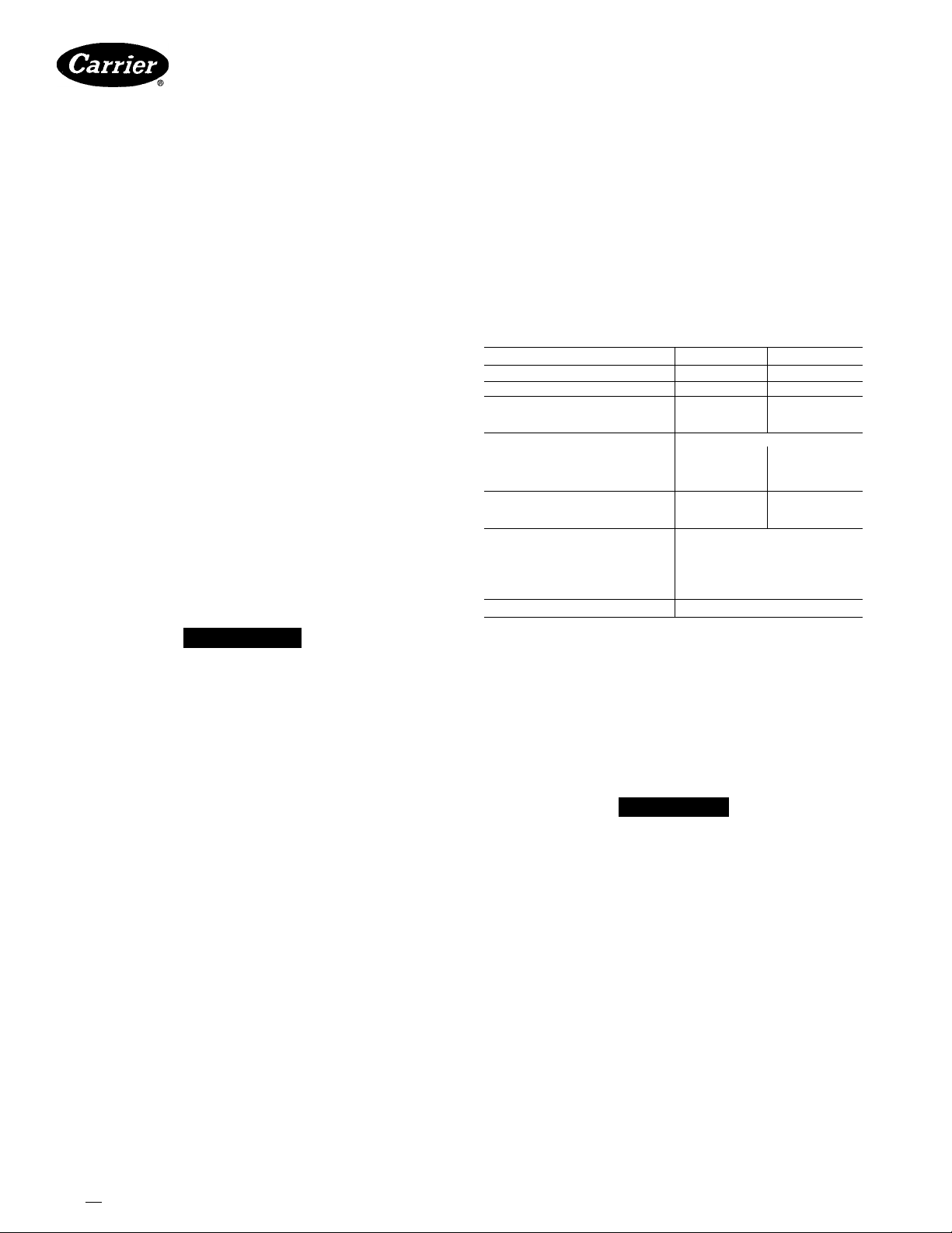
UNIT 38AF
OPER WEIGHT (lb)
REFRIGERANT*
COMPRESSOR
Oil (pts)
Crankcase Heater Watts
CONDENSER AIR FAN
Number...Rpm
Diameter (in.)
Motor Hp (NEMA)
Nominal Cfm Total
CONDENSER COIL
Face Area (sq tt)
Storage Capacity (lb)f
CONTROLS
Pressurestat Settings
FUSIBLE PLUG
*Unit is factory supplied with holding charge only.
tStorage capacity of condenser coil with coil 80% full of liquid R-22
at 124 F
Table 1 — Physical Data
007 008
300 400
22 22
46 8 0
40
Propeller; Direct Drive
1 1075 1 1075
22 22
'/2 v?
3500 4300
108
168 18 0
High Cutout
Cut-in
Low Cutout
Cut-In
426 ± 7 psig
320 ± 20 psig
27 ± 4 psig
67 ± 7 psig
200 F
40
17 7
INSTALLATION
Step 1 — Complete Pre-Installation Checks
UNCRATE UNIT — Remove unit packaging except for
the top skid assembly and wood bumpers, which should
be left in place until after unit is rigged into place.
INSPECT SHIPMENT — File claim with shipping com
pany if shipment is damaged or incomplete.
CONSIDER SYSTEM REQUIREMENTS
• Consult local building codes and National Electrical
Code (NEC) for special installation requirements.
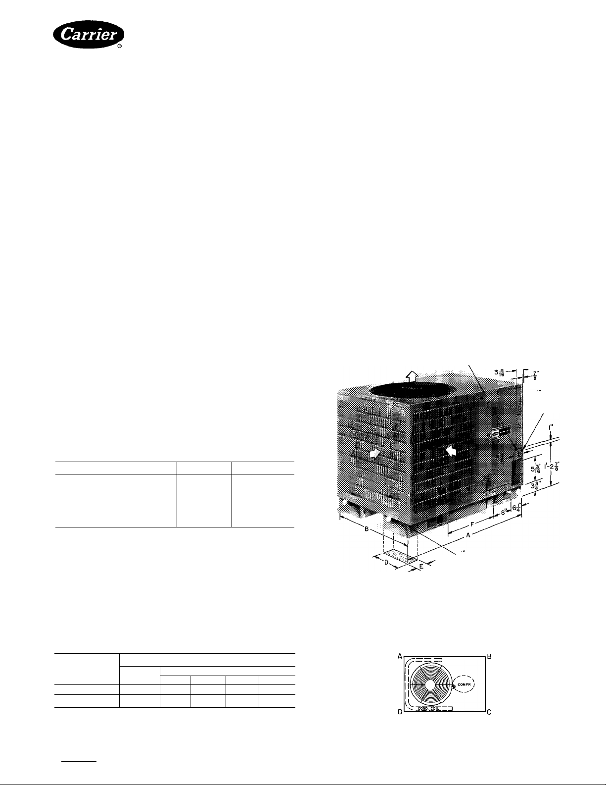
• Allow sufficient space for airflow clearance, wiring,
refrigerant piping, and servicing unit. See Fig. 1.
• Locate unit so that condenser airflow is unrestricted
on all sides and above. Refer to Fig. 1.
• Unit may be mounted on a level pad directly on base
channels or mounted on raised pads at support points.
See Table 2 for weight distribution based on recom
mended support points.
NOTE: If vibration isolators are required for a parti
cular installation, use data in Table 2 to make proper
selection.
Manufacturer reserves the right to discontinue, or change at any time, specifications or designs without notice and without Incurring obligations.
BookM |4 PC111 Catalog No 563-852 PrintedinUSA Form38AF-1SI Pg 1 4-85 Replaces: New
Tab I3al2a
For replacement items use Carrier Specified Parts
Step 2 — Rig and Mount the Unit
A CAUTION
Be sure unit panels are securely in place prior to
rigging.
RIGGING — These units are designed for overhead
rigging only. Traverse base channels are provided with
1 -1 / 2 in. rigging holes that are located 1 -3/ 4 in. from each
end. Rig with top skid packaging assembly and wood
bumper strips in place to prevent unit damage by rigging
cable. As further protection for coil faces, plywood sheets
may be placed against sides of unit, behind cables. Run
cables to a central suspension point so that angle from the
horizontal is not less than 45 degrees. Raise and set unit
down carefully.
If it is necessary to roll unit into position, mount unit
on longitudinal rails, using a minimum of 3 rollers. Apply
force to rails, not unit. If unit is to be skidded into posi
tion, place it on a large pad and drag it by the pad. Do not
apply any force to unit.
Raise from above to lift unit from rails or pad when
unit is in final position.
Page 2
38AF
HEATING & COOLING
Step 3 — Complete Refrigerant Piping
Connections
SIZE REFRIGERANT LINES — Consider length of
piping required between condensing unit and evaporator,
amount of liquid lift, and compressor oil return. See
Table 3 and also refer to Part 3 of Carrier System Design
Manual for design details and line sizing. Refer to evap
orator installation instructions for additional information.
USE FILTER DRIER AND MOISTURE INDICATOR
— The filter drier is factory supplied. Moisture indicator
(sight glass) is a field-installed option and should be
installed just after liquid line shutoff valve. Do not use a
receiver; there is none provided with unit and one should
not be used.
MAKE PIPING CONNECTIONS — Remove block-off
in corner post and unsweat caps from liquid and suction
lines.
NOTE: Unit is shipped with R-22 holding charge. System
pre.ssure must be relieved before unsweating caps.
Pass nitrogen or other inert gas through piping while
brazing to prevent formation of copper oxide.
Install field-supplied thermostatic expansion valve(s)
to evaporator section. If 2 thermostatic expansion valves
are installed for 2-step cooling, install field-supplied
liquid line solenoid valve ahead of the second expansion
valve.
Air-Cooled Condensing Units
PROVIDE SAFETY RELIEF —A fusible plug is located
in unit liquid line. Do not cap this plug. If local code;
requires additional safety devices, install as directed.
Step 4 — Complete Electrical Connections
POWER WIRING — Unit is factory wired for voltage
shown on nameplate. Provide adequate fused disconnect
switch within sight of unit, readily accessible, but out of
reach of children. Provision for locking switch open (ofO
is advisable to prevent power from being turned on while
unit is being serviced. Disconnect switch, fuses, and field
wiring must comply with National Electrical Code and
local code requirements.
Route power wires through opening in unit side panel
and connect in unit control box as shown on unit label
diagram and Fig. 2. Unit must be grounded.
Affix crankcase heater warning sticker to unit dis
connect switch.
CONTROL CIRCUIT WIRING — Control voltage is
24 volts. See Fig. 3 and unit label diagram for fieldsupplied wiring details. Route control wires through
opening in unit side panel to connection in unit con
trol box.
if" HOLE FIELD POWER SUPPLY
DIMENSIONS (ft-in.)
UNIT 38AF 007 008
Length A 2-9
Width
Height
Base Rail Width D 0-10'/2
Minimum Support
Lift opening
separation
NOTE Units may be installed with any one side, except compressor access
side, within one ft of wall or other airflow obstruction as long as remaining
sides have at least 3 ft clearance Compressor side access is always 3 feet
Units may be located side by side with a minimum of 3ft between units
Allow at least a 5-ft clearance above the unit
B 2-9 2- 8Va
c 2-8
E 0-4 0- 4
F
1- 0’/4
4- 0%
2-11 '/s
O-IO'/j
1-10
Fig. 1 — Dimensions (ft-in.)
Table 2 — Weight Distribution
WEIGHT (lb)
UNIT 38AF
007 300
008 410
Oper
Wt
A B C
54
75
Support Point
78 100
116
D
68
133 86
LEFT
l-b rigging HOLE (8)
REAR
RIGHT
i HOLE
CONTROL
POWER
FRONT
TOP VIEW
Manufacturer reserves the right to discontinue, or change at any time, specifications or designs without notice and without incurring obligations.
Book 11 14 PC111 Catalog No 563-852 PrintedInUSA Form38AF-1SI Pg2 4-85 Replaces: New
Tab |3al2a
For replacement items use Carrier Specified Parts
Page 3

38AF
HEATING A COOLING
Table 3 — Liquid Line Data
MAX
UNIT 38AF
007
008
NOTE: Values shown are for units operating at 45 F saturated suction
and 95 F entering air
3-PHASE
CONN TO
DISCONNECT
PER N E C
NOTE: Pigtail connections can use copper or aluminum wire Factorysupplied connectors must be used when aluminum wire is used
ALLOWABLE
LIQUID
LIFT (it)
70
70
___________________________
-GROUND LEAD
. SPLICE CONNECTIONS
FIELD WIRING
FACTORY WIRING
Max Allowable
Pressure Drop
LIQUID LINE
(psi)
7
7
------
GROUNDING LUG
3-PHASE COND UNIT
Max Allowable
Temp Loss
(F)
2
2
YEL-
BLK-
-BLU -
Fig. 2 — Line Power Connections
JUMPER
TERMINAL
BLOCK
UNIT
CONTROL
BOX
Air-Cooled Condensing Units
Table 4 — Electrical Data (3-Ph/60-Hz)
UNIT FAN
38AF
007
008
FLA — Full Load Amps
ICF — Maximum Instantaneous Current Flow
LRA — Locked Rotor Amps
MCA — Minimum Circuit Amps per NEC Section 430-24
MOCP — Maximum Overcurrent Protection
RLA — Rated Load Amps (compressor)
•Units are suitable for use on electrical systems where voltage supplied
to the unit terminals is not below or above the listed limits
tFan motor is single phase
j230 volts
Volts
Nameplate
208-230
460 414
575 518 666
208-230
460 414 528
575 518 666 76 188 25 2 9Í
Supplied*
Min Max
187
187
ICF
253 140 36 3 60 29
71
528
58
253 186 44 4
93
MOCP
MCA
(Fuse)
166 25
14.9
20 9
20
60 29
25 1 5
FLAT
Before starting unit, crankcase heaters must be on for '
24 hours to be sure all refrigerant is out of the oil. To
energize crankcase heaters, proceed as follows; set space
thermostat above ambient so there will be no demand for
cooling. Close field disconnect. The crankcase heaters '
are now energized.
Evacuate and Dehydrate entire refrigerant system
by either of the methods described in Carrier Standard
Service Techniques Manual, Chapter 1, Section 1-7.
Charge System — Refer to Carrier Standard
Service Techniques Manual, Chapter 1, Section 1-8.
Using liquid charging method and charging by weight
procedure, charge to a clear sight glass. After proper
charge has been determined, indicate this amount on
unit’s aluminum informative plate section entitled
“Refrig./System R-22.”
To Start Unit — Assuring that crankcase heater has
been on for 24 hours and field disconnect is closed, set
room thermostat below ambient. Unit compressor will
start after a 15-second delay.
COM
PRESSOR
RLA LRA
26 7 137
1 5 12 1 69
2.9t 9.6 55
32 5 183
152 91
124
73
SERVICE
Crankcase Heater prevents refrigerant migration and
compressor oil dilution during shutdown when com
Fig. 3 — Remote Thermostat Wiring
pressor is not operating. If crankcase heater is daenergized for more than 6 hours, both compressor service
valves must be closed.
START-UP
Preliminary Checks
1. Check that all internal wiring connections are tight
and that all barriers, covers and panels are in place.
2. Field electrical power source must agree with unit
nameplate rating.
3. All service valves must be open.
4. Crankcase heaters must be firmly seated into com
pressor crankcase.
Condenser Fan is supported by a reinforced wire
guard to which the fan motor is bolted.
Figure 4 shows proper mounted fan position.
Lubrication
FAN MOTORS have permanently sealed, lubricated
bearings. Do not oil.
COMPRESSOR also has its own oil supply.
CONDENSER FAN ADJUSTMENT (Fig. 4) — Shut
off unit main power supply. Remove condenser fan
assembly (grille, motor, motor cover and fan) and loosen
fan hub setscrews. Adjust fan height as shown in Fig. 4.
Leak Test entire refrigerant system by pressure method
described in Carrier Standard Service Techniques
Manual, Chapter 1, Section 1-6. Use R-22 at approxi
mately 25 psig backed up with an inert gas to a total
pressure not to exceed 245 psig.
Manufacturer reserves the right to discontinue, or change at any time, specifications or designs without notice and without incurring obligations.
Book 11 14 PC111 Catalog No 563-852 PrintedinUSA Form38AF-1SI Pg3 4-85 Replaces: New
Tab I3al2a
For replacement items use Carrier Specified Parts.
Tighten setscrews and replace fan assembly.
Cleaning Coils ^ Coils can be cleaned with a vacuum
cleaner, washed out with water, blown out with com
pressed air, or brushed (do not use wire brush). Fan
motors are drip proof but not waterproof.
Page 4

38AF
1
HEATING A COOLING
Clean coil annually or as required by location or out
door air conditions. Inspect coil monthly, and clean as
required. Fins are not continuous through coil sections.
Dirt and debris may pass through first section, become
trapped between the row of fins and restrict condenser
airflow. Use a flashlight to determine if dirt or debris
has collected between coil sections. Clean coil as follows:
1. Turn off unit power.
2. Disconnect fan motor leads. Note position of leadsfor
reconnection.
3. Remove screws holding top cover in place. Do not
remove fan motor or orifice.
4. Remove top cover assembly from unit (see Fig. 5).
Be especially careful not to damage coil fins.
5. Using a water hose, or other suitable equipment, flush
down between the sections of coil to remove dirt and
debris.
6. Clean the remaining surfaces in the normal manner.
,7. Reposition outer coil sections. Reinstall top cover
assembly. Make certain fan motor leads are in com
pressor compartment before replacing screws. Care
must be taken to prevent damage to coil fins.
8. Reconnect fan motor leads.
9. Replace all screws.
Air-Cooled Condensing Units
MOTOR
Fig. 4 — Condenser Fan Adjustment
OUTLET
NOTE: Top cover must come off
Fig. 5 — Pivot and Support Top Cover
Manufacturer reserves the right to discontinue, or change at any time, specifications or designs without notice and without Incurring obligations.
Book|1 |4 PC111 Catalog No 563-852 PrintedinUSA Form38AF-1Sl Pg4 4-85 Replaces: New
Tab l3al2a
For replacement items use Carrier Specified Parts.
Page 5

38AF
HEATING & COOLING
TROUBLESHOOTING GUIDE
COMPRESSOR DOES NOT RUN
Contactor Open
Power off — restore power.
Fuses blown — replace with correct fuses after finding
cause and correcting.
Transformer dead — replace transformer if primary
windings are receiving power.
Thermostat circuit open — check thermostat setting.
Circuit breaker tripped — check for excessive com
pressor current draw (140% FLA maximum allowable).
Low-pressure switch open — check for refrigerant under
charge or obstruction of indoor airflow.
High-pressure switch open — check for refrigerant over
charge or obstruction of outdoor airflow.
Connections loose — tighten all connections.
Compressor stuck — see compressor service literature.
Compressor motor thermostat open — check for exces
sive motor temperature.
Contactor Closed
Compressor leads loose — check connections.
Motor windings open — see compressor service
literature.
Single phasing — replace blown fuse.
COMPRESSOR CYCLES ON
HIGH-PRESSURE SWITCH
Condenser Fan On
High-pressure switch faulty — replace switch.
Airflow restricted — remove obstruction.
Air recirculating — clear airflow area.
Noncondensables in system — purge and recharge as
required.
Refrigerant overcharge — purge as required.
Line voltage incorrect — consult power company.
Refrigerant system restrictions — check or replace filter
drier, expansion valve, etc.
Condenser Fan Off
Fan slips on shaft — tighten fan hub setscrews.
Motor not running — check power and capacitor.
Motor bearings stuck — replace bearings.
Motor overload open — check overload rating. Check for
fan blade obstruction.
Motor burned out — replace motor.
Air-Cooled Condensing Units
COMPRESSOR CYCLES ON
LOW-PRESSURE SWITCH
Evaporator Air Fan Running
Filter drier plugged — replace filter drier.
Expansion valve power head defective — replace power
head.
Low refrigerant charge — add charge. Check low-
pressure switch setting.
Airflow Restricted
Evaporator coil iced up — check refrigerant charge.
Evaporator coil dirty — clean coil fins.
Indoor air filter dirty — clean or replace filters.
Indoor air dampers closed — check damper operation
and position.
Evaporator Air Fan Stopped
Electrical connections loose — tighten all connections.
Fan relay defective — replace relay.
Motor overload open — power supply.
Motor defective — replace motor.
Fan belt broken or slipping — replace or tighten belt.
COMPRESSOR RUNS BUT
COOLING INSUFFICIENT
Suction Pressure Low
Refrigerant charge low — add refrigerant.
Head pressure low — check refrigerant charge. Check
condenser air fan thermostat settings.
Indoor air filters dirty — clean or replace filters.
Expansion valve power head defective — replace power
head.
Evaporator coil partially iced — check low-pressure
setting.
Evaporator airflow restricted — remove obstruction.
Suction Pressure High
Compressor valves defective — see compressor service
literature.
Heat load excessive — check for open doors or windows.
Manufacturer reserves the right to discontinue, or change at any time, specifications or designs without notice and without incurring obligations.
Book|l |4 PC111 Catalog No 563-852 PrintedinUSA Form38AF-1SI Pg5 4-85 Replaces; New
Tab 13a12a
For reolacement items use Carrier Soecitied Parts
Page 6

38AF
HEATING & COOLING
Air-Cooled Condensing Units
Manufacturer reserves the right to discontinue, or change at any time, specifications or designs without notice and without incurring obiigations.
Book 11 14 PC111 Catalog No 563-852 PhntedinUSA Form38AF-1SI Pg6 4-85 Replaces: New
For renlacement Items use Carrier Specified Parts.
 Loading...