

Page 1
38AE
012,014,016
HEATING & COOLING
Air-Cooled Condensing Units
Installation, Start-Up and Service Instructions
50 and 60 Hz
INSTALLATION
Step 1 — Complete Pre-Installation Checks
UNCRATE UNIT — Remove unit packaging except for
the top skid assembly, which should be left in place until
after the unit is rigged into place.
INSPECT SHIPMENT — File claim with shipping com
pany if shipment is damaged or incomplete.
CONSIDER SYSTEM REQUIREMENTS
• Consult local building codes and National Electrical Code
(NEC, U.S.A.) for special installation requirements.
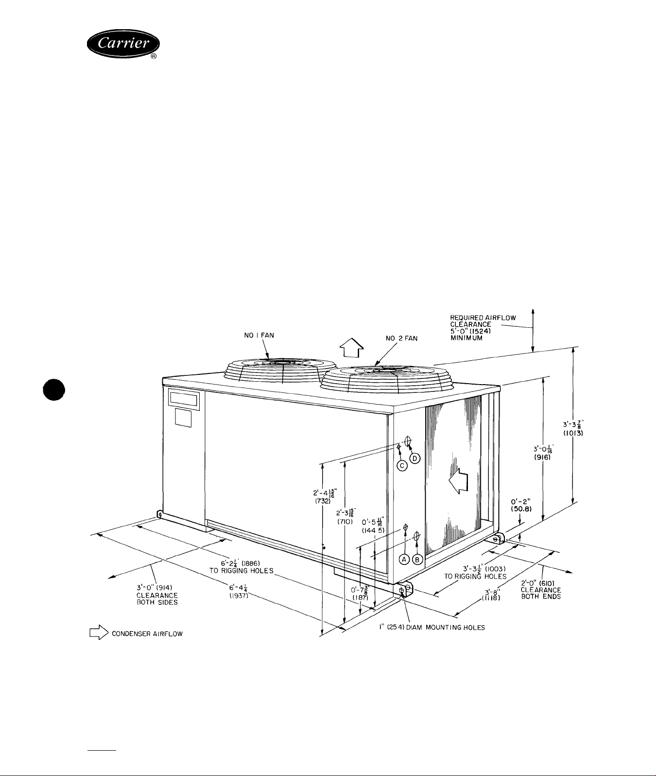
• Allow sufficient space for airflow clearance, wiring, re
frigerant piping, and servicing unit. See Fig. 1. See
Fig. 2 for unit component locations.
• Locate unit so that outdoor coil (condenser) airflow is
unrestricted on all sides and above.
• Unit may be mounted on a level pad directly on the base
channels or mounted on raised pads at support points.
See Table 2 for weight distribution based on recom
mended support points.
NOTE: If vibration isolators are required for a particular
installation, use the data in Table 2 to make the proper
selection.
A — 1V4 in. (32) diam. knockout for %-in. (16) ODM liquid line connection
B — 1%in (44 5)diam knockout for 1’/a in (28 6) (38AE012); 1%in (35) suction line connection (38AE014,016)
C — %-in (22.2) diam knockout for control power
D — 2-in (50 8) diam knockout for unit power
LEGEND
Certified dimension drawings are available on request.
NOTES:
1
SERVICE AREAS - Allow 3 ft (914) on both
sides and 2 ft (610) on both ends of unif for
servicing
Dimensions in parentheses are in (mm)
Fig. 1 - Physical Data and Dimensions (ft-in.)
Manufacturer reserves the right to discontinue, or change at any time, specifications or designs without notice and without incurring obligations.
Book|1 |1 PC 111 Catalog No 533-816 Printed in U S.A. Form 38AE-17SI Pg 1 4-92 Replaces: 38AE-10SI
Tab 3a 2a
Page 2
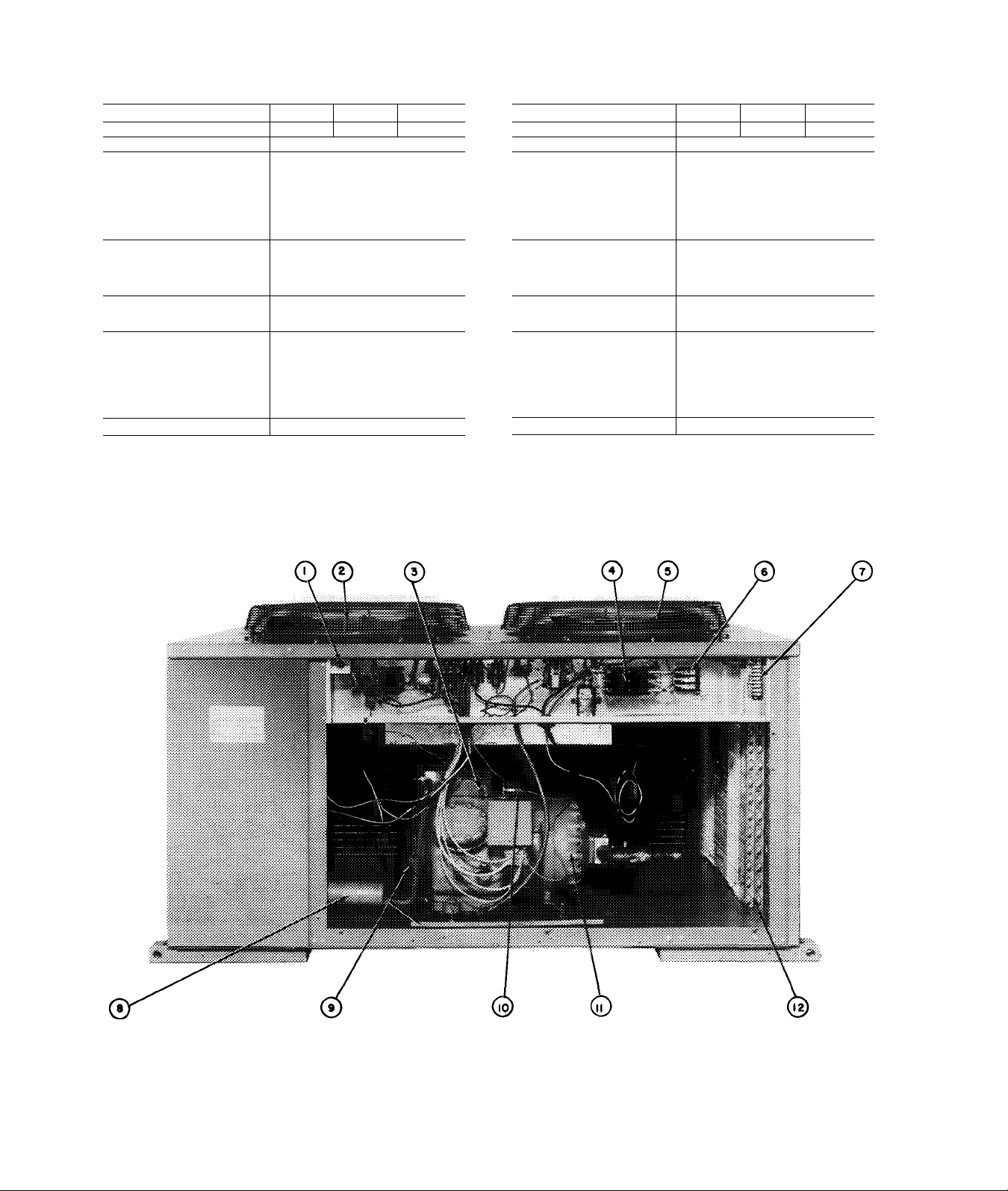
Table 1 — Physical Datrf^
ENGLISH
UNIT 38AE 012 014
OPERATING WEIGHT (lb)
REFRIGERANT (lb)‘ 22
COMPRESSOR
Model No.
Oil (pt)
Crankcase Heater Watts
Unloader Setting (pslg)
Load
Unload
OUTDOOR-AIR FANS
No. ...Rpm
Diameter (in.)
Motor Hp
Nominal Cfm Total
OUTDOOR COIL
Face Area (sq ft)
Storage Capacity (lb)t
CONTROLS
Pressurestat Settings (pslg)
High Cutout
Cut-in
Low Cutout
Cut-in
FUSIBLE PLUG
NEMA — National Electrical Manufacturing Association
‘Unit is factory supplied with holding charge only.
tStorage capacity is measured at liquid saturated temperatures of 125 F for
38AE012; 123 F for 38AE014; and 130 F for 38AE016
732 779
Reciprocating, Hermetic, 6 Cylinder;
06DD824 1 06DD328 I 06DD537
27 2
1750 Rpm
10
75
70 ± 1
60 ± 2
Axial Flow, Direct Drive
2 1075
24
V2
8800
29.2
40.3
395 ± 10
295 ± 10
29 ± 4
200 F
016
789
39 8
SI
UNIT 38AE
OPERATING WEIGHT (kg) 333 354
REFRIGERANT (kg)*
COMPRESSOR
Model No.
Oil (L)
Crankcase Heater Watts
Unloader Setting (kPa)
Load
Unload
OUTDOOR-AIR FANS
No. ...Rps
Diameter (mm)
Motor Hp
Nominal L/s Total
OUTDOOR COIL
Face Area (sq m)
Storage Capacity (kg)f
CONTROLS
Pressurestat Settings (kPa)
High Cutout
Cut-in
Low Cutout
Cut-in
FUSIBLE PLUG
NEMA — National Electrical Manufacturing Association
‘Unit is factory supplied with holding charge only
tStorage capacity is measured at liquid saturated temperatures of 51 7 C for
38AE012; 50 6 C for 38AE014; and 54 4 C for 38AE016
012 014
10
Reciprocating, Hermetic, 6 Cylinder;
06DD824 1 06DD328 | 06DD537
124
29.2 Rps
4.73
75
483 ± 6 9
414 ±13 8
Axial Flow, Direct Drive
2...17.9
610
1/2
4153
2.71
183 18.1
2724 ± 68 9
2034 ± 68 9
200 ± 27.6
414 ± 0
93 3 C
016
359
103
Low-Voltage Fuse
1 2 - No. 1 Fan
High-Pressure Switch
3 -
4 - Circuit Breakers
5 — No. 2 Fan
6 — Terminai Biock 1 (Unit Power)
7 — Terminal Block 2 (Control Power)
8 — Muffler
Fig. 2 — Component Locations
LEGEND
— Hot Gas Bypass Piping Stub (%-in ODM)
9
— Low-Pressure Switch
10
— Compressor
11
— Wraparound Coil
12
Page 3
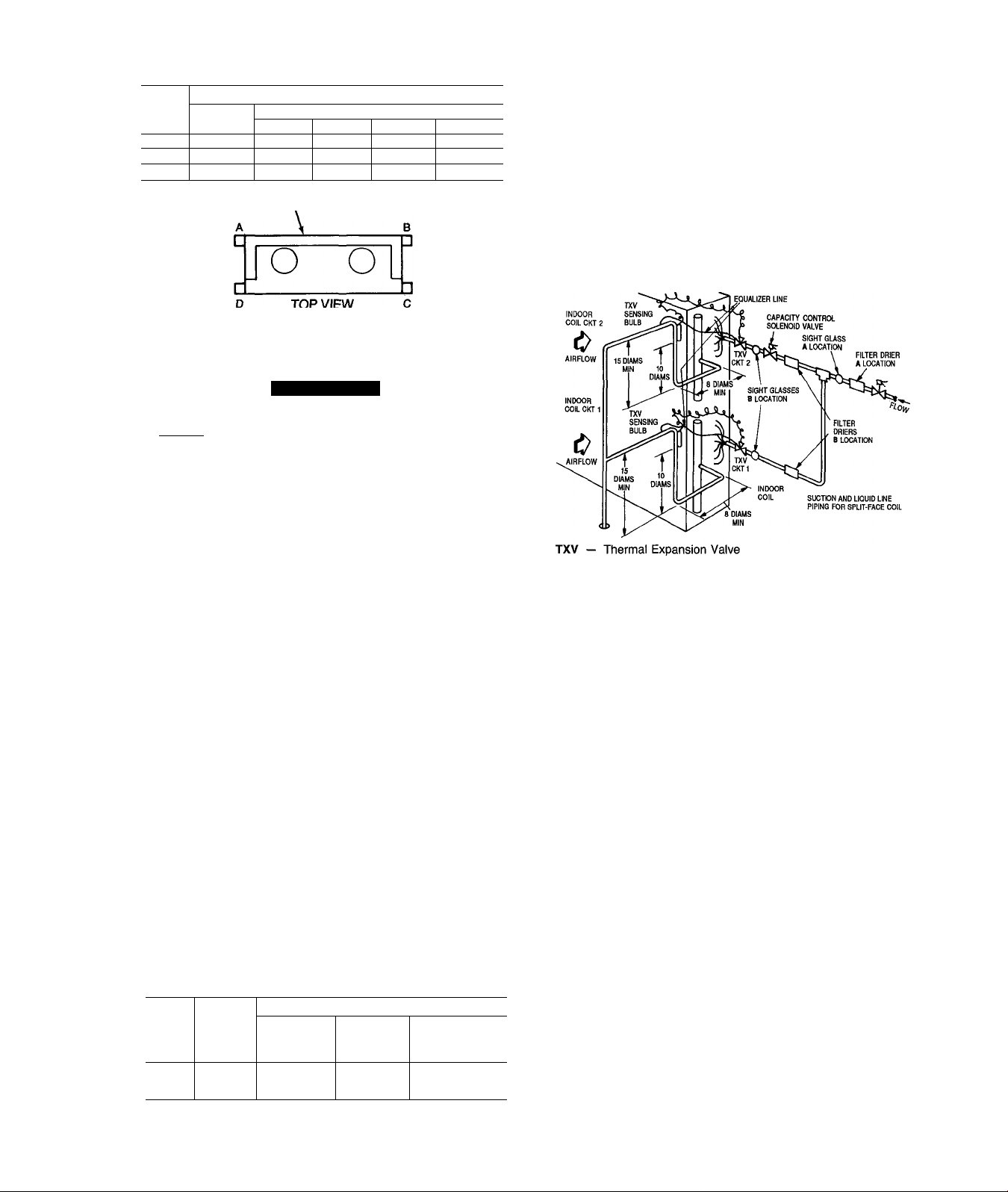
Table 2 — Weight Distribution
UNIT
38AE
r
012
014
016
Oper
Wt
732 (333) 142 (65)
779 (354)
789 (359) 143 (65)
WEIGHT - lb (kg)
Support Point
A B C
138 (63) 225 (102)
143 (65)
140 (64) 247 (112)
143 (65) 250 (114)
COIL
D
227(103)
249 (113)
253 (115)
INSTALL FILTER DRIER(S) AND MOISTURE INDICATOR(S) — Every unit should have a filter drier and liquidmoisture indicator (sight glass). In some applications, de
pending on space and convenience requirements, it may be
desirable to install 2 filter driers and sight glasses. One fil
ter drier and sight glass may be installed at A locations in
Fig. 3. Or, 2 filter driers and sight glasses may be installed
at B locations.
Select the filter drier for maximum unit capacity and min
imum pressure drop. Complete the refrigerant piping from
indoor unit to outdoor unit before opening the liquid and
suction lines at the outdoor unit.
TOP VIEW
Step 2 — Rig and Mount the Unit
A CAUTION
Be sure unit panels are securely in place prior to
rigging.
RIGGING — These units are designed for overhead rig
ging only. For this purpose, the transverse base channels
extend beyond the sides of the unit, with holes provided in
end plates to attach cables or hooks. Rig with top skid pack
aging assembly in place to prevent unit damage by the rig
ging cable. As further protection for the coil faces, plywood
sheets may be placed against the sides of the unit, behind
the cables. Run the cables to a central suspension point so
that the angle from the horizontal is not less than 45 de
grees. Raise and set the unit down carefully.
If it is necessary to roll the unit into position, mount the
unit on longitudinal rails, using a minimum of 3 rollers.
Apply force to the rails, not the unit. If the unit is to be
skidded into position, place it on a large pad and drag it by
the pad. Do not apply any force to the unit.
Raise from above to lift unit from the rails or pad when
unit is in final position.
COMPRESSOR MOUNTING — As shipped, the compres
sor is held tightly in place by self-locking bolts. Before
starting unit, loosen self-locking boits until the
flanged washer is stiil snug but can be moved side
ways with finger pressure. Do not remove ship
ping bolts.
Step 3 — Complete Refrigerant Piping
Connections
SIZE REFRIGERANT LINES - Consider the length of
piping required between outdoor unit and indoor unit (evap
orator), the amount of liquid lift, and compressor oil re
turn. See Table 3 and also refer to Part 3 of Carrier System
Design Manual for design details and line sizing. Refer to
indoor installation instructions for additional information.
Table 3 - Liquid Line Data
MAX
UNIT
38AE
*lnlet and outlet.
NOTE: Figures shown are for units operating at 45 F (7.2 C) saturated suction
and 95 F (35 C) entering air
ALLOW.
LIQUID
LIFT
ft(m)
52 (15 8) 7 (48.3)
012
67 (20.4) 7 (48 3)
014
016
82 (25) 7 (48 3)
Max Allow.
Press. Drop
psig (kPa)
LIQUID LINE
Max Allow.
Temp
Loss
•F (”C)
2(1 1) %
2(1 1)
2(1 1)
Filter Drier and
Sight Glass
Flare Conn.*
in. (mm)
Ye
Ys
Fig. 3
INSTALL LIQUID LINE SOLENOID VALVE - SOLE
NOID DROP — It is recommended that a solenoid valve
be placed in the main liquid line (see Fig. 3) between con
densing unit (38AE) and fan coil (40RR, 40RE). This valve
prevents refrigerant migration (which causes oil dilution) to
the compressor during the off cycle at low outdoor ambient
temperatures. The solenoid should be wired in parallel with
the compressor contactor coil. This means of electrical con
trol is referred to as solenoid drop control.
INSTALL LIQUID LINE SOLENOID VALVE (OP
TIONAL) - CAPACITY CONTROL - If 2-step cooling
is desired, place a solenoid valve in the location shown in
Fig. 3.
DO NOT USE A RECEIVER — No receiver is provided
with the unit. It is recommended that one NOT be used.
MAKE PIPING CONNECTIONS - Do not remove plas
tic dust plugs from suction and liquid line stubs in the com
pressor compartment until piping connections are ready to
be made. Pass nitrogen or other inert gas through piping
while brazing to prevent formation of copper oxide.
Install field-supplied thermostatic expansion valve(s) to
indoor section. If 2 thermostatic expansion valves are in
stalled for 2-step cooling, install field-supplied liquid line
solenoid valve ahead of the second expansion valve.
Locations of Sight Glass(es)
and Filter Drier(s)
Page 4
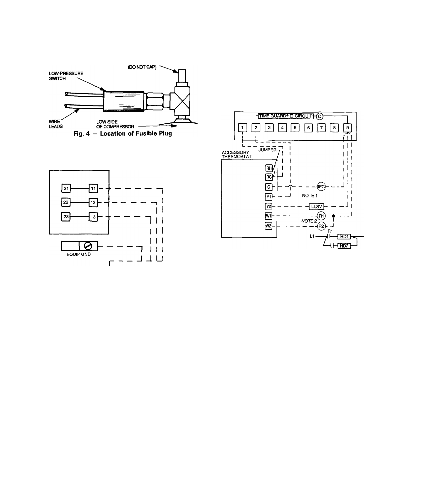
PROVIDE SAFETY RELIEF — A fusible plug is located
on the compressor crankcase (Fig. 4). Do not cap this plug.
If local code requires additional safety devices, install them
as directed.
FUSIBLE PLUG
TERMINAL BOARD (JB^) IN
38AE CONTROL BOX
Route power wires through opening in unit end panel to
connection in unit control box as shown on unit label dia
gram and Fig. 5. Unit must be grounded.
Affix crankcase heater warning sticker to unit disconnect
switch.
CONTROL CIRCUIT WIRING - Control voltage is 24 v.
See Fig. 6 and unit label diagram for field-supplied wiring
details. Route control wires through opening in unit end
panel to connection in unit control box.
TERMINAL BOARD (TB2) IN 38AE CONTROL BOX
I DISCONNECT PER NEC, USA. |
I_______________________________I
LEGEND
EQUIP GND — Equipment Ground
NEC — National Electrical Code
----------
Field Wiring
Fig. 5 - Main Power Supply Wiring
Step 4 - Complete Electrical Connections
POWER WIRING — Unit is factory wired for voltage shown
on nameplate. Provide adequate fused disconnect switch within
sight from unit and readily accessible from unit, but out of
the reach of children. Lock switch open (off) to prevent
power from being turned on while unit is being serviced.
Disconnect switch, fuses, and field wiring must comply with
national and local code requirements.
LEGEND
C
HD IFC LLSV R -
----------
----------NOTES:
1. Combination LLSV plus IFC va should not exceed 30 va.
2. Do not exceed 5 va (24 vac) per coil.
3. If va values shown in Notes 1 and 2 must be exceeded,
Compressor Contactor
Heating Device
Indoor-Fan Contactor
Liquid Line Solenoid Valve
Relay
Field Wiring
Factory Wiring
accessory relay transformer package 38AE900001.
R2
Fig. 6 “ Remote Thermostat Wiring
L2
use
Page 5

Table 4 - Electrical Data
(3 Ph/60 Hz)
UNIT
UNIT
38AE
012
Model
501
201
601
101
501
201
601
101
501
201
601
101
Nameplate
208-230 187
208-230 187 253
208-230 187 253 87 5
Volts
Supplied*
Min Max 1
380 342
460
575
380 342 418
460
575 518
380
460
575 518
414 528 29 1
518 660
414 528 31 7
342 418 49 3
414 528 40 7 124
253 62.5
418 35.0
660
660
MCA
22.8 67 35 157
69.3 199
38 0
25.6 73
33 0
ICF
178
101 50
112 60 26 5
274 125
153 80
100
MOCP
(Fuse)
100 43 6
81 40
100 49 3
84
50
40 17.9
60
50
(3 Ph/50 Hz)
UNIT
UNIT
38AE
FLA — Full Load Amps (Fan Motors)
ICF — Maximum Instantaneous Current Flow during start-up (LRA of compressor plus total FLA of fan motors)
kW — Total Fan Motor Input (kilowatts)
LRA — Looked Rotor Amps
MCA — Minimum Circuit Amps per NEC (U S.A ), Section 430-24
MOCP — Maximum Overcurrent Protection (amps)
RLA — Rated Load Amps (Compressor)
•Units are suitable for use on electrical systems where voltage supplied to the unit terminals is not below or above
the listed limits
Model
803 230
903 400 342
803 230
903 400 342 457 34 0 89 50
803
903
Name-
plate
230
400
Volts
Min
198
198
198
342
Supplied*
MCA
Max
264
457
264
264 66 9
457
47 5 134 75
31 4 80 50
51 0
43 0
ICF
149 75
206 100
121
MOCP
(Fuse)
COMPR FAN MOTORS (Single Phase)
RLA
32 9
20.0
35 7
22 1
47 9
29 3
LRA
170
93
77
62
191
104
69
266
145
120
96
COMPR
LRA
128 29 35
74 2.9 3.5
143
83 29 3.5
200 2.9 35
115
RLA
24 0
20.0
22 1 80
63 6
36.0
29 3
23 8
60
Total
Fans
FLA (ea)
Fan No.
4.3
4.3
23
1.8
43
43
23
1.8
43
43
2.3
1.8
FAN MOTORS
230 V (Single Phase)
Total
Fans
2
37
37
1 9
1.8
37
37
1 9
1.8
37
37
1 9
1 8
FLA (ea)
Fan No.
1 2
29
29
kW
3.5
35
START-UP
Evacuate and Dehydrate the entire refrigerant sys
tem by either of the methods described in Carrier Standard
Service Techniques Manual, Chapter 1, Section 1-7.
Leak Test the entire refrigerant system by the pressure
method described in Carrier Standard Service Techniques
Manual, Chapter 1, Section 1-6. Use R-22 at approxi
mately 25 psig (172.4 kPa) backed up with an inert gas to
a total pressme not to exceed 245 psig (1689 kPa).
Before starting the unit, the crankcase heaters must be
on for 24 hours to be sure all the refrigerant is out of the
oil. To energize the crankcase heaters, proceed as follows.
1. Set the space thermostat above ambient so there will be
no demand for cooling.
2. Close the field disconnect.
3. Turn the fan circuit breaker on. Leave the compressor
circuit breakers off. The crankcase heaters are now
energized.
Before Starting Unit check the following:
1. Compressor oil level must be at least within sight in the
compressor sight glass. Add oil if necessary (see Table
1 and Oil Charge section).
2. Compressor holddown bolts must be snug, but not tight.
Refer to Compressor Mounting section and tag on com
pressor foot.
3. All internal wiring connections must be tight; all barri
ers and covers must be in place.
4. Electrical power source must agree with unit nameplate
rating.
5. All service valves must be open.
6. Crankcase heater must be firmly locked into the com
pressor crankcase.
Page 6

Preliminary Charge — Refer to Carrier Standard Serv
ice Techniques Manual, Chapter 1, Section 1-8. By the liq
uid charging method and charging by weight procedure, charge
the units with approximately the following amounts of R22: 38AE012, 22 lb (10 kg); 38AE014, 23 lb (10.5 kg);
38AE016, 23 lb (10.5 kg). See Table 5.
Table 5 — Charging Data (R-22)
REFRIGERANT CHARGE - lb (kg)
UNIT
Required Charge
38AE
012
014 4.8 (2.2)
016
Above Clear
Sight Glass
3.0 (1.4) 22 (10)
3 4 (1 5) 23 (10.5)
Outdoor Unit
Total Charge
(Approx)
23 (10.5) 123 (50.6)
CONDENSING
TEMP
DURING
CHARGING - F (C)
125 (51.7)
130 (54.4)
Start the Unit — The field disconnect is closed, the
fan circuit breaker is closed, and the space thermostat is set
above ambient temperature so that there is no demand for
cooling. Only the crankcase heaters are energized. After
the heaters have been on for 24 hours, the unit can be started.
Close the compressor circuit breakers, and then reset the
space thermostat below ambient temperature, so that a call
for cooling is ensured.
Energize Branch Circuit — Set room thermostat above
ambient temperature. Close field disconnect switch. Be sure
that compressor crankcase heaters are operating. Allow crank
case heaters to operate a minimum of 24 hours before start
ing unit.
To Start Unit set room thermostat below ambient. Af
ter starting unit, there will be a delay of at least 3 seconds
before compressor starts.
Oil Charge (see Table 1) —Allow unit to run for about
20 minutes. Stop unit and check compressor oil level. Add
oil only if necessary to bring oil into view in sight glass.
Use only Carrier-approved compressor oil. Approved oils
are:
Witco Chemical Corp.............................................Suniso 3GS
Texaco, Inc
Petroleum Specialties Co.........................................Cryol 150
.....................................................................
WF32
Do not reuse drained oil or use any oil that has been ex
posed to atmosphere. Procedures for adding or removing
oil are given in Carrier Standard Service Techniques Man
ual, Chapter 1, Refrigerants.
If oil is added, run unit for additional 10 minutes. Stop
unit and check oil level. If level is still low, add oil only
after determining that piping system is designed for proper
oil return and that the system is not leaking oil.
On demand for additional cooling capacity, the second
stage (TC2) of the cooling thermostat closes, energizing a
field-supplied liquid line solenoid valve (LLS) which opens.
This increases the suction pressure, causing the compressor
to operate at higher capacity.
When fan switch is set at AUTO., the indoor-air fan cy
cles with the compressor. When the switch is set at CONT,
the indoor-air fan runs continuously.
At shutdown, the Time Guard® II timer prevents the com
pressor from restarting for approximately 5 minutes.
In addition, a field-supplied solenoid valve wired in par
allel with the compressor contactor coil, shuts off the liquid
line to prevent refrigerant migration back to the compressor
during the off cycle.
Heating — The heating thermostat (TH) energizes a field-
supplied relay which operates heating controls and ener
gizes the indoor-fan relay. When the fan switch is set at
AUTO., the indoor-air fan cycles with the heating control.
The indoor-air fan runs continuously when the fan switch is
set at CONT.
Fan Cycling is employed for head pressure control. The
no. 2 fan responds to liquid line pressure, cycling on at ap
proximately 257 psig (1772 kPa) and off at approximately
126 psig (869 kPa).
Winter Start Control (If Required) — install Ac
cessory Package 38AE900021.
SERVICE
Capacity Control — A suction pressure-actuated un
loader controls 2 cylinders and provides capacity control.
Unloaders are factory set (see Table 1), but may be field
adjusted:
CONTROL SET POINT (cylinder load point) is adjustable
from 0 to 85 psig (586 kPa). To adjust, turn control set
point adjustment nut (Fig. 7) clockwise to its bottom stop.
In this position, set point is 85 psig (586 kPa). Then, turn
adjustment counterclockwise to desired control set point.
Every full turn counterclockwise decreases set point by 7.5
psig (51.7 kPa).
PRESSURE DIFFERENTIAL (difference between cylinder
load and unload points) is adjustable from 6 to 22 psig (41.4
to 152 kPa). To adjust, turn pressure differential adjust
ment screw (Fig. 7) counterclockwise to its back stop po
sition. In this position, differential is 6 psig (41.4 kPa).
Then, turn adjustment clockwise to desired pressure differ
ential. Every full turn clockwise increases differential by
1.5 psig (10.3 kPa).
Check Operation of all safety controls. Replace all
service panels. Be sure that control panel cover is closed
tightly.
OPERATING SEQUENCE
Cooling — When the first stage (TCI) of the cooling
thermostat closes, the timer starts. After approximately 3
seconds, the timer activates the compressor and fan motor
no. 1 contactor. When the liquid pressure builds to approx
imately 257 psig (1772 kPa), fan motor no. 2 is energized.
Page 7

Head Pressure Control by means of/an cycling is a
standard feature of 38AE012-016 units. The no. 2 fan cy
cles in response to changes in liquid pressure. The switch
cycles the fan off at 126 ± 4 psig (869 ± 28 kPa) as pres
sure decreases, and cycles back on at 257 (-1-5, -0) psig
(1772 [-f 103, -0] kPa).
CONTROL
SET POINT
ADJUSTMENT
NUT
PRESSURE
DIFFERENTIAL
ADJUSTMENT
SCREW
VALVE BODY
BYRASS
PISTON
Winter-Start Control (If Required) - install Ac
cessory Package 38AE900021.
Crankcase Heater prevents refrigerant migration and
compressor oil dilution during shutdown whenever com
pressor is not operating. It is wired into the control circuit,
cycling with the compressor, off when compressor is run
ning, and on when compressor cycles off.
Both compressor service valves must be closed when
ever crankcase heater is deenergized for more than 6 hours.
The crankcase heater is operable as long as the control cir
cuit is energized.
Outdoor Fans — Each fan is supported by a formed-
wire mount bolted to the fan deck and covered with a wire
guard. The exposed end of the motor shaft is covered with
a rubber boot. In case a fan motor must be repaired or re
placed, be sure the rubber boot is put back on when the fan
is reinstalled and be sure the fan guard is in place before
starting the unit. Figure 9 shows the proper position of the
mounted fan. Fan motors have permanently lubricated
bearings.
DIFFERENTIAL SCREW'
SEALING CAP
(CAP MUST BE REPLACED
TO PREVENT REFRIGERANT LEAKAGE)
Fig. 7 — Compressor Capacity Controi Unloader
Time Guard® II Circuit provides for a delay of ap
proximately 5 minutes before restarting compressor after shut
down from safety device action.
On start-up, the Time Guard II timer causes a delay of
approximately 3 seconds after thermostat closes.
On compressor shutdown, the timer recycles for approx
imately 5 minutes. During this time, the compressor cannot
restart.
Refer to Fig. 8 and to label diagram on unit.
TIME DELAY TIMING SEQUENCE
----------
T1-T2
RUNNING TIME
p«
------
3SEC
-------------------------
wimmmmmmimiri.
----------
»■
5 MIN
»■
WIA DENOTES CLC6ED CONTACTS
Fig. 8 — Timer Sequence Chart
Lubrication
FAN MOTORS have sealed lubrication bearings. No pro
visions for lubrication are made.
COMPRESSOR has its own oil supply. Loss of oil due to a
leak in the system should be the only reason for adding oil
after the system has been in operation. See Oil Charge
section.
Page 8

Cleaning Coils — The coils can be cleaned with a vac
uum cleaner, washed out with water, blown out with com
pressed air, or brushed (do not use wire brush). Fan motors
are drip-proof but not waterproof.
Clean outdoor coil annually or as required by location or
outdoor air conditions. Inspect coil monthly, and clean as
required. Fins are not continuous through coil sections; dirt
and debris may pass through first section, become trapped
between the 2 rows of fins (38AE012) or 3 rows of fins
(38AE014, 016) and restrict outdoor airflow. Use a flash
light to determine if dirt or debris has collected between
coil sections. Clean coil as follows:
1. Turn off unit power.
2. Remove screws holding rear comer posts and top cover
in place. Pivot top cover up 12 to 18 in. (305 to 457
mm) and support with a rigid support. See Fig. 10.
3. Remove clips securing tube sheets together at the return
bend end of the coil. Carefully spread the ends of the
coil rows apart by moving the outer sections. See
Fig. 11.
4. Using a water hose, or other suitable equipment, flush
down between the sections of coil to remove dirt and
debris.
5. Clean the remaining surfaces in the normal manner.
6. Reposition outer coil sections.
7. Reinstall clips which secure tube sheets.
8. Replace top cover and rear comer posts.
Fig. 10 — Pivot and Support Top Cover
RIGID
SUPPORT
Page 9

TROUBLESHOOTING
PROBLEM SOLUTION
COMPRESSOR DOES NOT RUN
Contactor Open
1. Power off
2. Fuses blown in field power circuit 2 After finding cause and correcting, repiace with correct size
3. Transformer dead 3. Replace transformer if primary windings are receiving power.
4. Thermostat circuit open 4. Check thermostat setting.
5. Time Guard® il circuit defective
6. Circuit breaker tripped
7. Low-pressure switch open
8. High-pressure switch open
9. Loose electrical connections
10. Compressor stuck 10. See 06D compressor service literature.
11. Compressor motor thermostat open 11. Check for excessive motor temperature.
Contactor Closed
1. Compressor leads loose
2. Motor windings open
3. Single phasing
COMPRESSOR CYCLES ON HIGH-PRESSURE SWITCH
Outdoor Fan On
1. High-pressure switch faulty
2. Airflow restricted
3. Air recirculating
4. Noncondensables in system
5. Refrigerant overcharge 5. Purge as required
6. Line voltage incorrect
7. Refrigerant system restrictions
Outdoor Fan Off
1. Fan slips on shaft
2. Motor not running
3. Motor bearings stuck
4. Motor overload open
5. Motor burned out
COMPRESSOR CYCLES ON LOW-PRESSURE SWITCH
Indoor-Air Fan Running
1. Filter drier plugged
2. Expansion valve power head defective
3. Low refrigerant charge
Airflow Restricted
1. Coil iced up
2. Coil dirty
3. Air filters dirty
4. Dampers closed
Indoor-Air Fan Stopped
1. Electrical connections loose
2. Fan relay defective
3. Motor overload open
4. Motor defective
5. Fan belt broken or slipping
1. Restore power
fuse.
5. Repiace Time Guard ii circuit.
6. Check for excessive compressor current draw aiiowabie (140%
FLA maximum).
7. Check for refrigerant undercharge, obstruction of indoor airflow,
or whether compressor suction shutoff valve is fully open Make
sure liquid line solenoid (if used) is open.
8. Check for refrigerant overcharge, obstruction of outdoor airflow,
air in system, or whether compressor discharge valve is fully
open. Be sure outdoor fan(s) is operating
9. Tighten all connections.
1. Check connections.
2 See 06D compressor service literature.
3. Replace blown fuse
1 Replace switch.
2 Remove obstruction.
3. Clear airflow area.
4 Purge and recharge as required.
6. Consult power company
7. Check or replace filter drier, expansion valve, etc.
1 Tighten fan hub setscrews.
2. Check power and capacitor.
3. Replace bearings
4. Check overload rating. Check for fan blade obstruction
5. Replace motor.
1. Replace filter drier.
2. Replace power head.
3 Add charge. Check low-pressure switch setting
1. Check refrigerant charge
2. Clean coil fins.
3. Clean or replace filters.
4 Check damper operation and position.
1 Tighten all connections.
2. Replace relay.
3. Power supply
4. Replace motor.
5. Replace or tighten belt
Page 10

TROUBLESHOOTING (cont)
PROBLEM SOLUTION
COMPRESSOR RUNNING BUT COOLING INSUFFICIENT
Suction Pressure Low
1. Refrigerant charge low
2. Head pressure low
3. Air filters dirty
4. Expansion valve power head defective
5. Indoor coll partially iced
6. Indoor airflow restricted
Suction Pressure High
1. Compressor valve defective
2. Head load excessive
UNIT OPERATES TOO LONG OR CONTINUOUSLY
1. Low refrigerant charge
2. Control contacts fused
3. Air in system
4. Partially plugged expansion valve or filter drier
SYSTEM IS NOISY
1. Piping vibration
2. Compressor noisy
COMPRESSOR LOSES OIL
1. Leak in system
2. Crankcase heaters not energized during shutdown
3. Improper interconnecting piping design
FROSTED SUCTION LINE
1. Expansion valve admitting excess refrigerant
HOT LIQUID LINE
1. Shortage of refrigerant due to leak
2. Expansion valve opens too wide
FROSTED LIQUID LINE
1. Restricted filter drier
COMPRESSOR WILL NOT UNLOAD
1. Defective unloader
2. Defective capacity control solenoid valve (if used)
3. Miswired capacity control liquid line solenoid (if used)
4. Weak, broken, or wrong valve body spring
COMPRESSOR WILL NOT LOAD
1. Miswired capacity control liquid line solenoid (if used)
2. Defective capacity control solenoid valve (if used)
3. Plugged strainer (high side)
4. Stuck or damaged unloader piston or piston ring(s)
1. Add refrigerant
2. Check refrigerant charge.
Check outdoor-air fan thermostat settings.
3 Clean or replace filters.
4. Replace power head.
5. Check low-pressure setting.
6. Remove obstruction.
1. See 06D compressor service literature.
2 Check for open doors or windows in vicinity of fan coil.
1. Add refrigerant.
2. Replace control.
3. Purge and evacuate system.
4. Clean or replace.
1. Support piping as required.
2. Check valve plates for valve noise Replace compressor if bear
ings are worn
1. Repair leak.
2. Check wiring and relays Check heater and replace if defective.
3 Check piping for oil return. Replace if necessary.
1. Adjust expansion valve.
1. Repair leak and recharge.
2. Adjust expansion valve.
1. Remove restriction or replace.
1 Replace unloader.
2 Replace valve.
3 Rewire correctly.
4. Replace spring
1. Rewire correctly.
2. Replace valve.
3 Clean or replace strainer.
4 Clean or replace the necessary parts
10
Page 11

Page 12

f
Copyright 1992 Carrier Corporation
Manufacturer reserves the right to discontinue, or change at any time, specifications or designs without notice and without incurring obligations.
Book! 1 II PC 111 Catalog No. 533-816 Printed in U S A. Form 38AE-17Si Pg 12 4-92 Repiaces: 38AE-10Si
Tab 3a 2a
 Loading...