

Page 1
Carrier
Instaitation, Start-Up
at|d Service Instructions
Air-Cooled Condensing Units
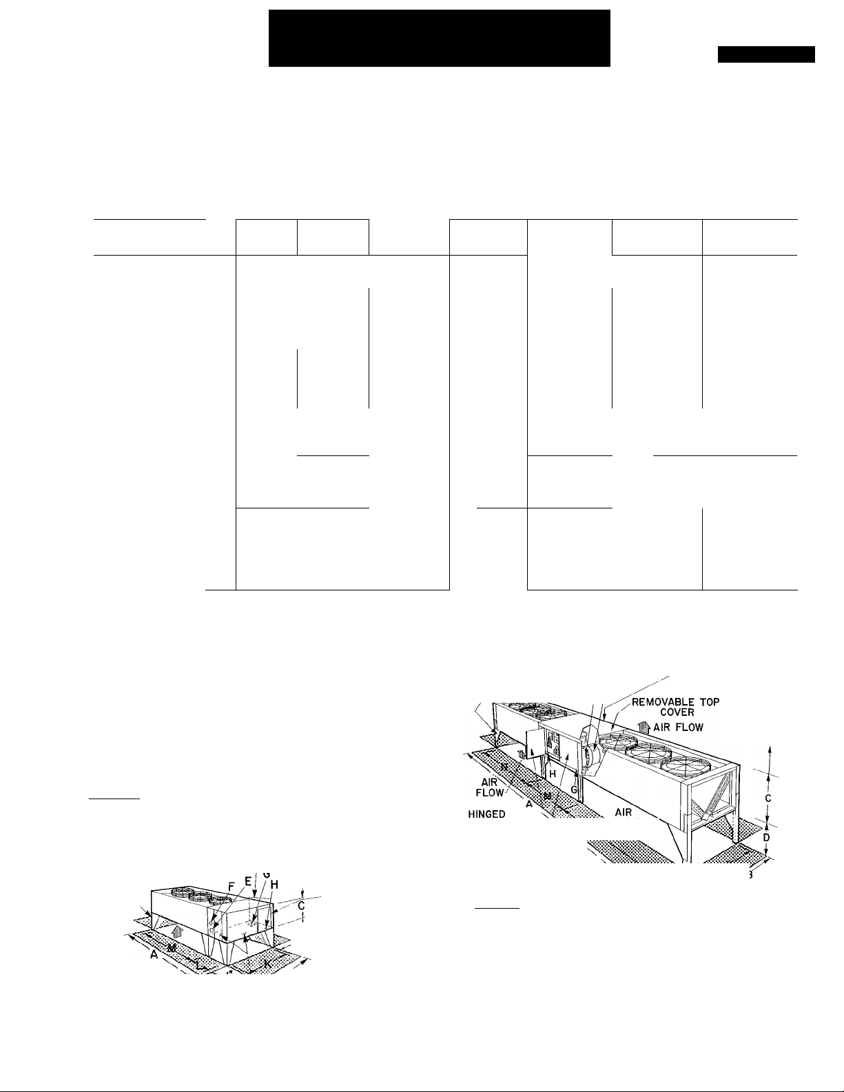
Table 1 — Dimensions
024 thru 084
38AD
024 028
DIMENSIONS (ft-in
Length
Width
Height w/o Legs
Leg Height
Mtg Holes
Corner Legs
Middle Legs
CONNECTIONS (in
Suction (ODM)
Liquid (ODM) %
OPENINGS (in.)
Suction
Liquid
Control (4 holes)
Power
*Unit 38AB084 has two suction connections
.)
A
В
C
D 1-0 or 2-0 1 —6 or 2—2
0- 1У2
li
( J
Ik
3- 8V4
0- OVe
3-10
L
M
N
- -
)
E
F
1- %
G
H
3~
38AD
11У4
2-
4Ve
0- 1У2
3- 8У4
0- 0%
3-10
1- У
13-0
3-3Ve
9-4Уа
1-Ув
2-У
Ув
З-Ув
12
38AD
044
-10%
- 2
1 - 8
2
-У
5
- 7У
2
-У
- 7У
3
- 7Уб
-юу
8
2-У
V
38AD
034
4-ЮУ4 6 - ОУ4
3- 1У 3
0- ly
4- 7У4
0- оу
4- 8У 5
4 5
1- У4
2
1-У
5
ЗВАВ
054
24-4
3-11У
2- 4У
Ì —4 ог 2—0 1-6
0- 1Уб
3- 8У
0- ОУв
3-10
2-У4
1
З-У4
38АВ
064 084
4-1ОУ4
3-
Г/в
ОГ 2—2
0-
4-
7У
ОУв
0-
r/i6
1 _8 ог 2-4
4- 8У
9
-4У
-ЗУ4
5
-5У
9
2
-Ve*
1
38АВ
24-4
6- ОУ4
3- 1Ув
0- ly
5- 9У4
0- ОУв
5-10У
(2)5
3
%
(2) ЗУ
REMOVABLE HINGED CONTROL
TOP COVER g|4, BOX DOOR
\0NLY) REQUIRED OVERHEAD
AIRFLOW# \^'; / /
_ _____
_ |H o"U
GUSSET
\ ^^si|^4-0"(B0TH SIDES)
38AD024
028, 034
4-0-Ny/ REMOVABLE
(BOTH SIDES)^ END PANELS
HINGED ACCESS DOOR-
CONTROL BOXi
AIR FLOW
GUSSET
38AD044
A..'- -’ll —
------------
(BOTH SIDES) end panels
REQUIRED OVERHEAD
AIR SPACE
8-0"
HINGED POWER
BOX DOOR
?
4'-0"(B0TH SIDES)
^removable
GUSSET '‘t
CONTROL \,
BOX COVERS \
38AB054,
064,084
• AIR FLOW THRU
Fig. 1 — Dimensions
AIR FLOW
CONDENSER
BOTTOM PANEL
OPENING
E F
(BOTH SIDES)
Certified dimension drawings are available on request
REMOVABLE REAR
m SPACE FOR SERVICE
PANEL
4'-0"
(BOTH SIDES)
AND AIR FLOW
REQUIRED
OVERHEAD
AIR SPACE
8'-0"
©Carrier Corporation 1972
Form 38AD-6SI
Page 2
Lift unit at points G,H, J, and K (Fig. 2). Use
eyebolts and washers supplied in parts package. Do
not sling unshielded unit Skidded unit may be
slung, provided sling does not contact unit sides.
Do not roll unskidded unit on pipes or wooden
pilings.
COM PR
SECTION
4-
4 ^
COIL 1
Ml SECTION 1
f j
r A -
“! . p
COIL
SECTION
COIL
SECTION
COMPR
SECTION :
^ -
Erect UnifeusMf^legs and gussets attached to unit
base skid(s) or frame. Adjust all corner legs to
desired height before attaching to unit.
38AD024,028,034 AND 044 UNITS - Block up
or suspend unit. With field-supplied bolts, bolt
corner leg and angle gusset to each corner of unit.
Bolt two center legs to bottom of unit where
compressor and coil sections meet. Lower unit.
38AB054,064 AND 084 UNIT - Block up or
suspend compressor (with coil) section. Bolt corner
leg and angle gusset to each corner at coil end. Bolt
two center legs to compressor end. Allow one set
of holes to project out past compressor section.
Bolt two center legs to bottom of unit where
compressor and coil sections meet. Lower unit.
Block up or suspend coil (only) section. Bolt
two corner legs and angle gussets to coil return
bend end. Butt coil (only) section against com
pressor compartment, allowing cod to rest on leg
projections. Remove top cover on compressor
compartment and bolt sections together at legs and
sides.
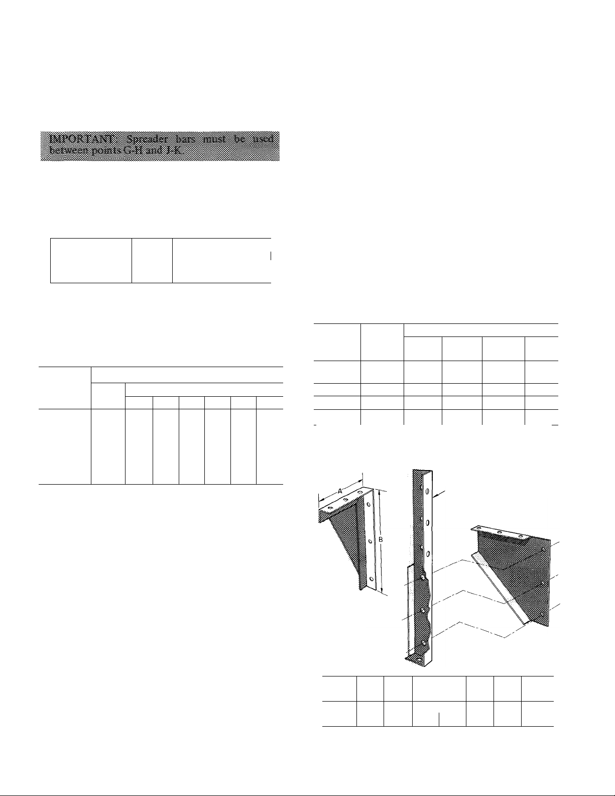
Table 3 — Legs and Gussets Provided
Fig. 2 — Weight Distribution and Lifting Points
Table 2 — Weight Distribution
WEIGHT (lb)
UNIT
38AD024
38AD028
38AD034
38AD044
38AB054
38AB064
38AB084
Total
1750 175
1900
2300
3200
3145 180
3830 245
4960 327
178 178 521
263 263 767
359
A B C D E
Leg Location
175 575
359 770
605 607
712 714
913 327
913
125
575
565
767 120 120
810 441
181
244
125
207 251
461
-
F
-
-
-
SKID REMOVAL
Remove the four bolts (each section) holding
top frame in place and lift frame from unit
(38AD024 thru 044 and 38AB054,064 units).
Compressor (with coil) Section — Raise and block
up one side of unit 8 inches. Remove the three
exposed hold-down bolts from base skid. Lower
unit and repeat on opposite side.
Coil (only) Section (38AB054,064 and 084) —
Raise and block up one end of unit 8 inches.
Remove the two exposed hold-down bolts from
base skid. Lower unit and repeat on opposite end.
ERECTING AND INTEGRATING ONE UNIT
Position Units 38AD028,044 and 38AB054,
064,084 so air flow is unrestricted on all sides and
on top (Fig. 1).
38AD024,034: any side except compressor end
may be installed against a wall if high leg setting is
used and other three sides are unrestricted.
Place 38AB and 38AD units on high leg setting if
accessory damper is used.
QUANTITY
38AB 38AD
024,028
-
-
054,064
084
‘Parts packages in units contain all mounting fasteners required
for attaching legs and gussets
CENTER LEG
A(in.)
B(in.)
‘Only 044 units use one-piece legs
034
044
38AD
024
16
24 24
Corner
Leg
- - 4 -
-
38AD
38AD 38AD
028 034 044
16 18 0
Center
Leg
4
4
4
CORNER LEG
26 20
Angie
Gusset
2
2
-
38AB
054 064
16
24
Fig. 3 — Legs and Gussets
Parts
Pkg*
4
- 1
4 1
ANGLE
GUSSET
38AB 38AB
084
18
26 28
20
1
1
Page 3
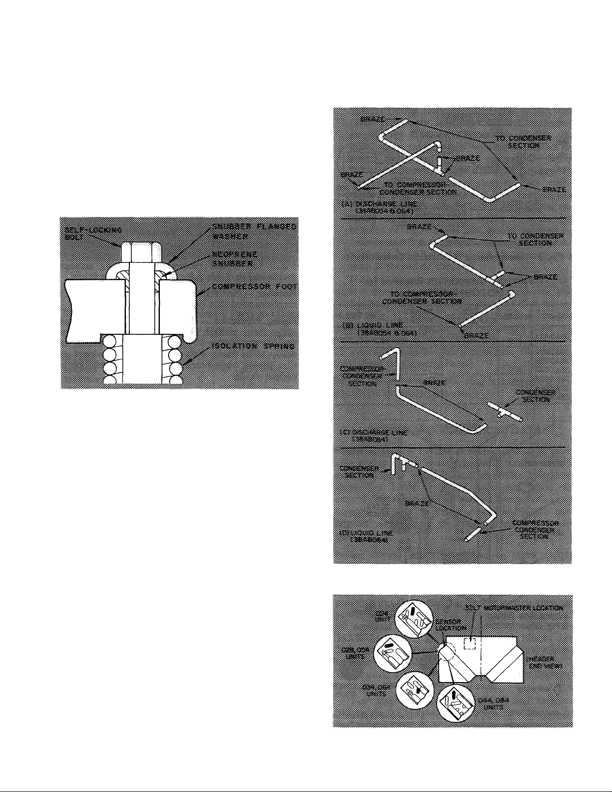
Compressor Mounting
38AD024,028,034 UNITS - As shipped, com
pressor is held down by special self-locking bolts
and plain lockwashers. After unit is installed,
remove the self-locking bolts one at a time and
reassemble with flanged washers and neoprene
snubbers as shown in Fig. 4. Special flanged wash
ers and neoprene snubbers are shipped in a cloth
bag tied to one of the compressor feet. Tighten all
four bolts. Then, loosen each until the flanged
washer can be moved sidewise.
38AD044, 38AB054,064 AND 084 UNITS (com
pressors are mounted on a common support
channel) — Remove the four shipping bolts from
mounting channels prior to start-up.
208- and 230-volt units, outdoor fan motor no. 1
(OFMj), located nearest the compressor, may be
used with MOTORMASTER without modification.
For 460- and 575-volt units, refer to Tabled for
field-supplied components needed with
MOTORMASTER.
Fig. 4 — Compressor Mounting
(38AD024,028 and 034)
Fan Thermostat — Route the thermostat control
bulb and capillary (located in compressor section)
thru grommeted hole in compressor section base
pan. Do not kink capillary. Position bulb in inlet
air stream and secure to inlet air flange adjacent to
compressor section. Use clamp and screw provided
in parts package.
If accessory head pressure control damper
section is used, secure bulb to air inlet side of
damper. Use hole in damper frame.
Integrate Unit (38AB054,064 and 084 only) —
Connect refrigerant piping between the two sec
tions, using materials furnished with unit. Arrange
discharge and liquid lines as shown in Fig. 5 and
braze as indicated.
Electrically connect unit control box and junc
tion box on coil (only) section by using flexible
fan conduit furnished in the unit. Use the mating,
quick-connect, polarized plugs furnished in the two
sections to make the wire connections.
Motormaster® (32 Series) Head Pressure Controller
— Refer to MOTORMASTER Instructions shipped
with this accessory, plus the following information.
Control box and sensor location is shown in
Fig. 6.
Electrical connections are shown in Fig. 7.
Refer to unit label diagram as required. On 200-,
Fig. 5 — Refrigerant Connections
Fig. 6 - MOTORMASTER Control Box
and Sensor Location
Page 4
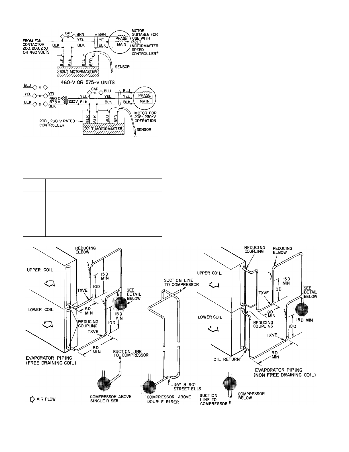
*Use 230-vo)t controller with 200-,208- or 230-volt motors
Fig. 7 — Motormaster® Electrical Connections
Table 4 — Components Required for
MOTORMASTER Use
UNIT MODEL
38AD024
38AD028
38AD034
38AD044
38AB054
38AB064
38AB084
600
100
600
100
RUN
CAPACITOR
HC96LH020
HC96LH030
TRANS
FORMER
HT01AH951
HT01AH959
HT01AH952
HT01AH954
MOTOR
HC46VL220or
HC46VL221
HC52TE230
REFRIGERANT PIPING
Refrigerant Line Sizes will depend on length of
piping required between condensing unit and evap
orator. Consideration must be given to liquid lift
and to compressor oil return. Refer to Part 3 of
Carrier System Design Manual for line sizing
information and Fig. 8 for recommended piping
details.
Single Pumpout Control — All units are factory
wired to operate on single pumpout control and
require a field-supplied liquid line solenoid valve,
sized for minimum pressure drop, to be installed
immediately ahead of each expansion valve. If unit
is to be used with a chiller, wiring modifications
may be necessary. Refer to 38AB Application
Data, Chilled Water Applications.
Refrigerant Drier and Moisture Indicator — A
filter-drier(s) and a liquid-moisture indicator are
shipped with unit for field installation. Refer to
Fig. 9 for typical recommended piping arrange
ments and to Table 5 for physical data on driers.
Receiver — No receiver is provided with unit. It is
recommended that one not be used.
Piping Procedure — Do not remove plastic dust
plugs from suction and liquid line stubs in com
pressor compartment until piping connections are
ready to be made. Pass nitrogen or other inert gas
thru piping while brazing, to prevent formation of
copper oxide.
NOTES
1 Lower split first on, last off
T7T
2 D as used in 8D etc, indicates the pipe diameter size as a measure of length
3 TXVE indicates Thermostatic Expansion Valve Equalizer Connection
Fig. 8 — Typical Piping Connections for Face Split Coils
Page 5

Fig. 9 — Recommended Filter-Drier(s)
and Sight Glass Locations
Table 5 — Filter-Drier Replacement Parts and Data
FILTER-DRIER
UNIT
38AD024
38AD028 KH43LE12) 2
38AD034
38AD044 KH49EA030
38AB054 KH49EA120 1
38AB064
38AB084 KH49EA040
* Replaceable cores only
Part No, Qty
KH43LE123
KH43LE121
KH49EA120
Conn.
Size
1
2
1
1
1
Replacement
Part No.
Same
=/s
%
%
iVs
iVs KH29EZ050*
iVs KH29EZ050*
Some
Same
KH29EZ050* 2
KH29EZ050* 2
Core
Qty
riser must be at least 15 pipe diameters high
and the bulb should be fastened 10 pipe
diameters above the preceding elbow.
3. Size the suction line from near evaporator thru
the 15 diameter long riser for high velocity.
Enter the suction pipe sizing charts in Carrier
System Design Manual at corrected design tons
(each evaporator split) and 80 feet equivalent
length (for 2° loss). Choose the smaller size
pipe, when reading falls between two sizes on
chart. Since the selection of suction piping
recommended for high velocity is approxi
mately 20 ft equivalent length, this sizing
method will result in about 0.5° friction loss
for that section. If a 2° loss is allowed for the
entire suction line, this leaves 1.5° for the
balance of suction line and should be sized on
that basis. This high-velocity sizing should be
adequate for oil return up the 15 diameter long
riser. It should be checked.
If an oil return connection at the bottom of the
suction header is supplied with an evaporator, this
connection must be teed in ahead of first mixing
elbow (Fig. 8). When the compressor is below the
evaporator, the riser at the evaporator does not
have to extend as high as the top level. After the
15 diameter riser has been provided, the suction
0
0
0
may elbow down immediately.
Safety Relief — A fusible plug is located on unit
liquid line before liquid valve.
2
3
WIRING AND ELECTRICAL DATA
Install field-supplied thermostatic expansion
valve in liquid line ahead of each evaporator
section. For two-step cooling, the solenoids used
must be wired to be opened by control from a
two-step thermostat
For example; two solenoids may be used with
three TXV’s — one of the solenoids serving a liquid
line feeding two of the TXV’s. When three
solenoids are used with three TXV’s, two of the
solenoids must be tied in parallel with the thermo
stat to serve the one liquid line feeding the two
TXV’s. The third solenoid operates independently
for the other step of cooling.
Suction Piping at Evaporator and TXV Bulb
Location
The purpose of these recommendations is to
achieve good mixing of the refrigerant leaving the
evaporator suction header for proper sensing by
the TXV bulb.
1. A minimum of two 90° elbows must be
installed upstream of the expansion valve bulb
location.
2. The thermal bulb must be strapped to a vertical
riser following the second elbow of item 1. This
Power Supply — Electrical characteristics of avail
able power supply must agree with unit nameplate
rating. Supply voltage must be within tolerances
shown in Table 6. Phase unbalance must not
exceed 2%. Operation of unit on improper supply
voltage or with excessive phase unbalance con
stitutes abuse and is not covered by Carrier
Warranty.
Power Wiring — All power wiring must comply
with applicable local and national codes. Install a
field-supplied branch circuit disconnect switch of a
type that can be locked “Off’ or “Open.” Run
power wires from the disconnect switch thru the
power opening (H on Fig. 1) on unit and connect
to terminal block just inside the opening. On
38AB084, there are two terminal blocks (on
208-volt and 230-volt units only). Each is limited
to 350 MCM maximum wire size (see Table 7).
These units are provided with two power openings
to accommodate two conduit runs.
For access to power opening and terminal
blocks on 38AD044, unlatch the two latches on
the outer hinged door and swing open outer door.
Remove screws on barrier panel and remove barrier
to expose wiring.
Page 6

Table 6 — Electrical Data (3-Phase, 60-Hz)
f
Shaded values are LRA drawn by first winding of
part-winding start units (not standard on 38AB054,064,
but may be field modified) See Note 1 Larger value is
total LRA.
FLA — Full Load Amps
ICF — Maximum Instantaneous Current Flow (sum of LRA of
LRA Locked Rotor Amps
MWA — Minimum Wire Amps per NEC, Section 430-24 Values
*Units are suitable for use on electrical systems where voltage
tUnits 38AB084 (208-, 230-volt only) have two power connections
last compressor to start and FLA of all other motors in
unit, and control circuit current)
based on maximum of 1% voltage drop in line.
supplied to the unit terminals is never below or above the listed
limits
Maximum wire size is 350 MCM each
*
On 38AD024 thru 034 units, power terminal
block is in the control box. Remove the outer
panel and remove the no. 10 screw on the door.
Swing open door, remove screws on barrier panel
and remove barrier panel. On 38AB054,064 and
084 units, remove two screws holding hinged sheet
metal barrier and swing open barrier.
Condenser fans must rotate clockwise when
viewed from above. If necessary, correct direction
of fan rotation by interchanging any two power
input wires at disconnect switch.
NOTES
1 Dual compressor units have a 4- to 12-second delay between
first- and second-compressor start-up Units are supplied with
either across-the-line or part-winding start, depending on unit
size and voltage Refer to Electrical Data table Where two LRA
values are shown, units are part-winding start, (all others are
across-the-line)
2 Units have factory-installed circuit breakers and/or pullout fuses
that meet NEC requirements for branch circuit over-current
protection and in-sight disconnect Consult local codes
3 Maximum Incremental Current Inrush during start-up is LRA
drawn by first winding of part-winding start unit (shaded area)
or across-the-line LRA of largest compressor when part-winding
start is not available
4 Fans no 1 and 4 have single-phase speed control motors on 208-
and 230-volt units
5 Units 38AB054 and 064 which have two contactors, can be
converted to part-winding start by addition of two time-delay
relays (Carrier part no FIN67SK001 for 208- and 230-volt units,
or no HN67SK002 for 460-and 575-volt units) Two additional
contactors are also required with 460- and 575-volt units to be
wired same as other part-wind compressors
Affix crankcase heater decal to unit disconnect
switch.
Control Circuit Wiring — Internal control voltage
on 38AD units is 115 volts. Internal control
voltage on 208- and 230-volt 38AB units is the
same as unit voltage. On 460- and 575-volt 38AB
units, it is 115 volts. All control circuit wiring must
comply with applicable local and national codes.
Remote control wiring must enter unit control box
thru control opening (G on Fig. 1) and connect to
terminal block inside the control box.
772
Page 7

Table 7 — Maximum Field Wire Sizes
UNIT
38AD
38 A B
CT — Compression Terminal (attached to terminal block)
TB — Terminal Block (with integral compression terminal)
SIZE
024,028,034
044
054,064
084
VOLTS
(60-Hzy
208
230
460
575
460
575
208
230
208
230
460
575
All 6 AWG to 350 MCM-
WIRE SIZE CONN.
6 AWG to 350 MCM
14 AWG to 2/0
6 AWG to 350 MOV!
6 AWG to 350 MCM
6 AWG to 3/0
TB
CT
TB
CT
CT
TB
&[1]--
[E--
0--
------------
lEh
E
--------------------------------
CR — Control Relay TC — Thermostat, Cooling
LLS — Liquid Line Solenoid
TB — Terminal Board (at unit) *Field Supplied
J<d_
TC2*
TWO STEP COOLING
38AB054, 064 AND 084
LEGEND
--"fea--
---------
Field Wiring
T
I
-I -
Fig. 10 — Control Circuit Wiring with Line Voltage
(115, 208- or 230-volt) Thermostat
, J
LINE VOLTAGE REMOTE CONTROL - Install
field-supplied line voltage thermostat(s) as shown
in Fig. 10 for two-step cooling. Wire liquid line
solenoid as shown.
LOW-VOLTAGE REMOTE CONTROL - Install
field-supplied accessories as shown in Fig. 11 or
Fig. 12 for either two-step cooling or two-step
cooling, one-step heating. Wire liquid line solenoids
as shown.
START-UP
Preliminary Checks
1. Compressor oil level must be visible at sight
glass in each compressor crankcase. Add oil if
necessary.
2. Each compressor must float freely on its
mounting springs.
3. All internal wiring connections must be tight,
and all barriers and covers must be in place.
Toggle switches for units 38AB054.,064 and 084
must be in “On” position.
4. Electrical power source must agree with unit
nameplate rating.
5. All service valves must be open.
6. Fan cycling thermostat sensing bulb must be in
air stream under fan no. 1.
7. Crankcase heater must be firmly locked into
the compressor crankcase.
Leak Test the entire refrigerant system by the
Pressure Method described in the Carrier Standard
Service Techniques Manual, Chapter 1, Section 1-6.
Use R-22 at approximately 25 psig backed up with
an inert gas to a total pressure not to exceed 245
psig.
Evacuate and Dehydrate the entire refrigerant
system by either of the methods described in the
Carrier Standard Service Techniques Manual,
Chapter 1, Section 1-7.
l-2i
38AB,054,064. 0^
SDRl
CR)
-----
---------------
•SDRir^
L-ll]
------
AHA — Adjustable Heat
cc — Cooling Compensator
CR — Control Relay
HD — Heating Device
IFR
IMS
LLS — Liquid Line Solenoid
R — Relay (Accessory)
SDR — Solenoid Dropping Relay *Field Supplied
Anticipator
— Indoor Fan Relay
— Indoor Motor Starter
(i^
—@k3^-
THERMOSTAT HHOTATOTZ
SUBBASE HH93AZ080
LEGEND
SR — Solenoid Relay
TB -- Terminal Board
TC — Thermostat, Cooling
TH — Thermostat, Heating
— Factory Wired
■ - Field Wired
-1 Terminal Board Conn.
n
at Unit
Fig. 11 — Control Circuit Wiring with
24-Volt Accessories (38AB Units Only)
—-ii
772
Page 8

CONTROL POWER AT 38AD UNIT
tll5-l-60 VOLT t
CR — Control Relay
HD — Heating Device
IFC — Indoor Fan Contactor
IFR — Indoor Fan Relay
LLS — Liquid Line Solenoid
R — Heating Relay (field-supplied 24-volt sealed coil, 10VA
SDR — Solenoid Dropping Relay
TB
TC
TH
--------------
------------^Jumper removed only when separate 24-volt power sources are
fTo control heating device and provide automatic indoor fan
maximum rating)
— Terminal Board
— Thermostat, Cooling
— Thermostat, Heating
Factory Wiring
Field Wiring
available for heating and cooling
operation on heating
Fig. 12 — Control Circuit Wiring with 24-Volt
Accessories (38AD units only)
Preliminary Charge — Refer to Carrier Standard
Service Techniques Manual, Chapter 1, Section 1-8,
for charging methods and procedures mentioned
below.
Charge system with approximately 25 lb of R-22
(75 lb for 38AD044, 38AB054,064 and 084 units)
by the Liquid Charging Method and Charging by
Weight Procedure.
Energize the Branch Circuit, set space thermostat
above ambient. Close field disconnect switch and
turn on unit circuit breakers. Be sure compressor
crankcase heater(s) is operating. Allow crankcase
heater(s) to operate a minimum of 24 hours before
starting unit.
To Start Unit, set space thermostat below ambient,
to ensure circuit operation. On 38AD044 and
38AB084, push control circuit reset button(s).
After starting unit, there will be a delay of about
' 15 seconds (12 seconds on 38AD044 and
38AB084) before first compressor starts.
Charging System
1. Block condenser coils to maintain 125 F con
densing temp at 280 psig, then add additional
charge to clear sight glass. (If long liquid lines
or vertical lifts greater than 25 ft are used, a
liquid line sight glass should be installed at
condensing unit and used for charging
purposes.)
2. After sight glass has cleared, additional charge
must be added per Table 8, to flood subcooler
circuits in condensers.
After Charging the System, allow unit to run for
about 20 minutes. Stop unit and check compressor
oil level. Add oil only if necessary to bring oil into
view in sight glass. If oil is added, run unit for
additional 10 minutes. Stop unit and check oil
level. If level is again low, add oil only after
determining that piping system is designed for
proper oil return and that the system is not leaking
oil. Check the operation of all safety controls.
Replace all service panels. Be sure that control
panel door is closed tightly.
Table 8 — Charging Data (R-22)
REFRIG CHG (lb)
UNIT
38AD024
38AD028
38AD034 7 99
38AD044 15
38AB054
38AB064 10
38AB084
*For maximum system capacity without receiver
fAt 120 F condensing temp with condenser 80% full of
liquid
NOTE
Values shown do not include charging requirements for
cooling coils and piping
Sub-cooler
Coil*
8
8
12
21
REFRIG
STORAGE
CAP. (Ib)t
70
77
161
154
198
322
SERVICE
Capacity Control is by either one or two suction
pressure actuated unloaders. Each controls two
cylinders. Unloaders are factory set (see Table 9)
but may be field adjusted. No. 1 unloader is on
cylinder bank on same side of compressor as
terminal box.
CONTROL SET POINT (cylinder load point) is
adjustable from 0 to 85 psig. To adjust, turn
control set point adjustment nut (Fig. 13) clock
wise to its bottom stop. In this position, set point
is 85 psig. Then, turn adjustment counterclockwise
to desired control set point. Every full turn
counterclockwise decreases set point by 7.5 psig.
PRESSURE DIFFERENTIAL (difference between
cylinder load and unload points) is adjustable from
6 to 22 psig. To adjust, turn pressure differential
adjustment screw (Fig. 13) counterclockwise to its
back stop position. In this position, differential is 6
psig. Then, turn adjustment clockwise to desired
pressure differential. Every full turn clockwise
increases differential by 1.5 psig.
772
Page 9

Table 9 — Physical Data
UNIT
OPER WT (lb)
REFRIGERANT
Oper Chg (lb)*
COMPRESSOR
Number
Model
Cylinders 4 4
Oil (pt)
Crankcase Htr
Pro tection
Cap. Control
No. 1
Load
Unload
No. 2 Unioader Settings (psig)
Load
Unload
COND FANS
Number
Rpm
Diam (in.)
Motor Hp (ea)
Cfm
COND COIL
Sections
Face (sq ft) 35 4 39 0
Capacity (lb)t 70 77
ELEC CONTROLS
Pre^surestat Dual
, Cutout
High ^ ^ .
Cut-in
, Cutout
Low ^ ^ .
Cut-in
Pressurestat Capacity Control
Cutout
Cut-in
Pressurestat
Cutout
Thermostat
No. 1
No. 2
Thermostat
PRESS. RELIEF
DISCHARGE LINE
CHECK VALVE
38AD024
1750
28 0 30 5
1
0ÓED250 06EE266
14
76 78
58 60
-
3 3 3 3
1140 1140
26 30 30 30
18,200
1
— —
- -
38AD028
1900 2300 ' 3200 3145 3830
1
14 19
Solid State &. Ckt Bkr Thermotector & Ckt Bkr
76 76
58 58
1
25,200 28,200
1
29 Psig
44 Psig 45 Psig
1 1
38AD034
35 5
1
06EE275
6
78
60 66
1140
1
1 2
49 6 60 4 78 0
99
38AD044 38AB054 38AB064
R-22
66 0
Reciprocating Hermetic — 1750 rpm
2
06EA
250
5 Psi Above Suction Pressure
Opens
06ED
4 4
14
Suction Pressure Cylinder Unioader(s
Unloader Settings (ps
88
Axic 1 Flow;
1 140
31,000
161
Time Guard Circuit**
29 Psig 29 Psig
57 Psig
87 Psig
1 Pressure Contro
Oi
Fan Cycling
Opens, 70 F;
Opens, 57 F;
Discharge Line
290 F; Closes, 210 F
Fusibl
2
06EA
250
14
1 25 Watts
Direct Drive
Plafe Fins; 3-rowt
375 Psig
275 Psig
Closes, 75 F
Closes, 62 F
e Plug
57 0
2
06EE
250
4
14
-
-
-
-
275
6
19
g)
79
66
76
58
6
1140
30
50,400
154 198 322
1
2
71
0
2
06EA
275
6
19
~
-
-
-
06EE
275
6
19
79
66
76
58
S
1140 1 140
30 30
56,400
2
99 2
63 Psig
57 Psig
87 Psig
2
38AB084
4960
132 0
06EA
299
6
19
Solid State
& Ckt Bkr
-
-
_
-
62,000
120 8
2
06EE
299
6
19
79
66
76
58
6
2
2
■*Approximate charge for maximum system capacity Holding charge
factory supplied with all units
fUnit 38AD044 and 38AB084 have 4 row coil
Time Guard Circuits
BASIC FUNCTIONS OF TIME GUARD CIRCUIT
on all units provide for normal (12 to 15 sec)
momentary delays after the thermostat closes and
before compressor(s) start. The circuit also pro
vides for a longer delay (4 min 45 sec to 5 min
30 sec) in the event of thermostat short cycling or
momentary power failure.
^Storage capacity at 120 F condensing temp with condenser 80%
full of liquid
**Short-cycle protection
38AD024 THRU 044 UNITS
In addition to the basic functions, timers in
these units provide additional delays for oil
pressure switch bypass (40 sec), winter start
provision (150 sec) bypass of low-pressure switch
and part-winding start (1 sec), if used.
772
Page 10

38AB084UNIT
Timers in this unit provide basic function, plus
40 sec bypass for oil failure switch and 1 sec delay
to accomplish part-winding start.
For specific sequence for each unit, refer to
Timing Charts in Fig. 14.
CONTROL
SET POINT
ADJUSTMENT
NUT
PRESSURE
DIFFERENTIAL
ADJUSTMENT
SCREW
VALVE BODY
BYPASS
PISTON
Control Circuit Reset
38AD024 THRU 044 AND 38AB084 - Control
circuit locks out on these units in the event of oil
pressure loss, excessive motor temperatures, or
excessive discharge temperatures Reset is
accomplished by pushing reset button(s) in unit
control box.
38AB054 AND 064 — Loss of oil pressure or
excessive motor temperatures cause control circuit
lock out on these units Reset is accomplished by
pushing reset button on oil failure safety
switch(es). All other safety controls on each unit
are automatic reset, with restart accomplished
through unit timers.
Oil Pressure Safety Control (OPS) for each com
pressor will stop unit if oil pressure differential is
not established or maintaineci at either compressor.
If OPS stops unit, determine and correct the
cause (such as loss of compressor oil or flooded
compressor) before restarting unit. Failure to do so
will constitute abuse. Equipment failure due to
abuse is not covered by the Warranty To restart
unit, push manual reset button in unit control box
(except 38AB054 and 064 units). Reset button is
on OPS on 38AB054 and 064.
i BBi :
1 €10
AMI
ÇÂÂ2~
)BB|
1BB2
DIFFERENTIAL SCREW'
SEALING CAP
(CAP MUST BE REPLACED
TO PREVENT REFRIGERANT LEAKAGE)
Fig. 13 — Capacity Control Valve
)^l2SECî2 —H
■
1 h—1 SEC m.5
H
-----
1 h—5SEC i2
) EEi i i
1 1— ^
--------------------
ri
38AD024 THRU 044 UNITS
-4-45 SEC
38AB054 THRU 064 UNITS
NOTE- BLACK INDICATES CLOSED CONTACTS
38AB084 UNITS
Fig. 14 — Timing Charts
40 SEC î 5
-5MIN----------------------
F—2-6 SEC
i
Compressor Motor Protection on 38AD024 thru
^ 044 and 38AB084 consists of three temperature
sensors (one for each phase) embedded in the
motor windings, and solid state modules in unit
control box.
Sensors are part of a temperature bridge. If a
motor winding overheats, the bridge circuit will
unbalance and a silicone-controlled rectifier in the
module will de-energize a relay which opens a set
of normally open contacts in the module and stops
the compressor.
If one sensor fails, it can be jumped with a
i
75-ohm, 2-watt resistor. When checking or testing
module, do not apply more than 6 volts across
sensor terminals. Many test instruments exceed this
voltage rating; check before using.
If a component in a module fails on 38AD024
thru 044, the entire module must be replaced. On
38AB084, the transformer is external to the
module and may be replaced separately. Replace
transformer with a Carrier specified balanced
transformer.
To restart compressor after shutdown due to
motor protection trip, push control circuit reset
button in unit control box.
Safety Relief — All 38AB,AD units are protected
against excessive pressure by a fusible plug inserted
in the liquid line.
^ Winter Start Control — On 38AB units (not
necessary on 38AD units because the timer
supplies this function), install a liquid line pressurestat (Carrier part no. HK02AB026) and evaporator
freeze-up protector (defrost thermostat, Carrier
part no. HH22UA025).
38AD control circuits incorporate a 150 sec
onds timed bypass of the low-pressure switch to
in
Page 11

allow unit to start under low-ambient conditions.
An evaporator freezestat must also be installed in
series with the control thermostat(s) to prevent
coil freeze-up (See lower part of Fig 15 — EDT
Wiring section.)
LIQUID LINE PRESSURESTAT - Connect to
system liquid line service valve port. Connect
switch into control circuit as shown on unit label
diagram or in Fig. 15. Pressurestat is set to cutout
at 5 psig with a differential of 10 psig. Do not
change setting
DEFROST THERMOSTAT - Position switch so
that moisture cannot enter switch insulator. Install
control with approximately 2 in. of top of thermo
stat capillary passing thru lower part of evaporator
cod and with remainder of capillary inserted
between fins on entering air side of coil. Connect
thermostat electrical contacts into indoor cooling
thermostat circuit or in series with compressor
holding coil.
Thermostat is set to cut out at 25 F and cut in
at 55 F. Contact rating is 16 amps and 230 volts.
As evaporator coil frosts, cod fin temperature
drops to thermostat cutout setting, and stops
compressor. Evaporator fans keep running to
defrost cod with room air. As indoor coil defrosts,
fin temperature will rise to thermostat cut-in
setting. Compressor starts when cooling is required.
NOTE. Use a defrost thermostat on all systems
operating with outdoor temperatures below 45 F.
Fan Adjustment — When replacing a fan, adjust fan
until top surface of hub plate is below the top of
the orifice ring as indicated in Fig. 16. Then,
tighten both setscrews, located over the keyway of
the fan hub of the motor shaft. Seal recessed area
of fan hub bore with Permagum to prevent rusting.
Fig. 15 — Unit Wiring Changes for
Winter Start Control
Lubrication
FAN MOTORS have permanently lubricated bear
ings. No provisions for lubrication are made.
COMPRESSOR has its own od supply. Loss of oil
due to a leak in the system should be the only
reason for adding oil after the system has been in
operation.
To Add or Remove Compressor Od
1.
Stop compressor and close suction service valve.
Pump down compressor to 2 psig. Stop com
pressor and close discharge shutoff valve.
Relieve crankcase pressure by disconnecting
2.
line, at compressor, which goes to low-pressure
connection of od safety switch.
3.
Add oil thru oil filter connection.
4.
Remove od thru drain plug in bottom cover.
Remove small amounts of od thru od discharge
connection with compressor running.
3»^ A
...............................
i Fan
............
roft
L " '
38AD034
3SAD044
38aS«54
38A8iSii4
Fig. 16 — Fan Adjustment
11
Page 12

i
For replacement items use Carrier Specified Parts.
Manufacturer reserves the right to change any product specifications without notice.
CARRIER AIR CONDITIONING COMPANY • SYRACUSE, NEW YORK
Tab 4 Form 38AD-6S1 Supersedes 38AD-5SI Printed in U.S.A. 37 3 4-72 Codes B and MS Catalog No. 533-860
 Loading...