

Page 1

Carrier
Start-Ito cmd
Senrìce Instructions
5 ü
Heat Pump - Outdoor Unit
Table 1 — Physical Data
'~oig
; 1750 Rpm
06DA537
Direct Drive
13 Per Incl
о D
5
15_^
65+3
272
178
016
22
45
6
10
75 ^
3
1 120
22
%
13,000
26 2
51
364
264
29
54
70
75
57
62
UNIT 38ЛС ___ _ ___,
OPERAJJNG WЕЮH]!,(I
REFRIGERANT
Ope rating Charge (lb)*
’comp'ressor'''^"
Model
Cyl inders
Oil (pts)
Crankcase Heater (watts)
Outdoor FANS
Number
Rpm; 60-Hertz 1 120
Diameter (in.) 22
Motor hp
OUTDOOR COIL
Face Area (sq ft)
Capacity (lb)t ^
PRESSURESTAT
(Cut-in (psig)
Low
(Cut-in (pstg)
Liquid Line
Cutout (psig)
Cut-in (psig)
Thermostat^
Defrost
n- u I- jOpens (F)
Discharge
Fan Cycling
*Approximate charge with 25 feet of interconnecting piping
Use appropriate charging charts for actual charging of unit
tRefrigerant storage capacity at 120 F condensing temperature
with condenser 80 percent full of liquid
(Closes (F)
No. (F)
N.. 3 lÿ'"- <■=>
oses (F)
lens (F)
oses (F)
012.....
890 ____ _
500 '
_36 _
Recip Herme
06DA337
6
10
_ 75 ^
Propel I
2
кз
_
___
__
Plate Fins;
18 4
32
320
245
42
60
65
3-Rc
17
45 + 3
INITIAL START-UP
Evacuate and Dehydrate the entire refrigerant
system by either of the methods described in
Carrier Standard Service Techniques Manual.
Leak Test entire refrigerant system by Pressure
Method described in Carrier Standard Service
Techniques Manual. Use refrigerant specified for
unit at approximately 25 psig backed up with an
inert gas to a total pressure not to exceed 250 psig.
Before Starting Unit, check the following:
1. Compressor oil level must be at least within
sight in compressor oil sight glass. Add oil if
necessary.
2. Compressor hold-down bolts must be snug but
not tight. Refer to installation instructions or
tag on compressor foot.
3. All internal wiring connections must be tight;
all barriers and covers must be in place.
4. Electrical power source must agree with unit
nameplate rating.
5. All service valves must be open.
6. Fan cycling thermostat (head pressure control)
sensing bulb must be in air flow under fan no. 1.
7. Crankcase heater must be firmly locked into
compressor crankcase.
Energize Branch Circuit — Close field disconnect
switch to energize compressor crankcase heater.
Make sure room thermostat is set in a manner to
prevent unit(s) from starting at this time.
Heating/Cooling Thermostat (HH03AT064) has an
adjustable heat anticipator for both first- and
second-stage heating circuits.
SETTINGS — Set adjustment lever for first-stage
anticipator at 0.24 (left-hand side). Set adjustment
lever for second-stage anticipator (right-hand side)
as follows:
One Strip Heater - 0.21
Two Strip Heaters — 0.42
Three Strip Heaters — 0.63
Outdoor Thermostat — Refer to 40RT strip heater
Installation Instructions for details on adjustments
of this thermostat (if used).
To Start Unit — After compressor crankcase heater
has been on for at least 3 hours set room
thermostat so unit will start on desired cycle.
On initial start of 38AC016, unit should be run
for 20 minutes on heating cycle so any con
taminants will be collected in larger drier.
HEATING — Place thermostat selector to “Heat”
and set temperature selector above room ambient.
COOLING — Place thermostat selector to “Cool”
and set temperature selector below room ambient.
To Charge System — Refer to Carrier Standard
Service Techniques Manual, Chapter 1, for charging
methods and procedures mentioned below. Refer
to charging charts as applicable.
1. Be sure to use the correct refrigerant (see
charging chart).
2. Regulate refrigerant drum valve to maintain
suction pressure at 49 psig on 38AC012 and 80
psig on 38AC016 while charging.
©Carrier Corporation 1969
Form 38AC-2SS
Page 2
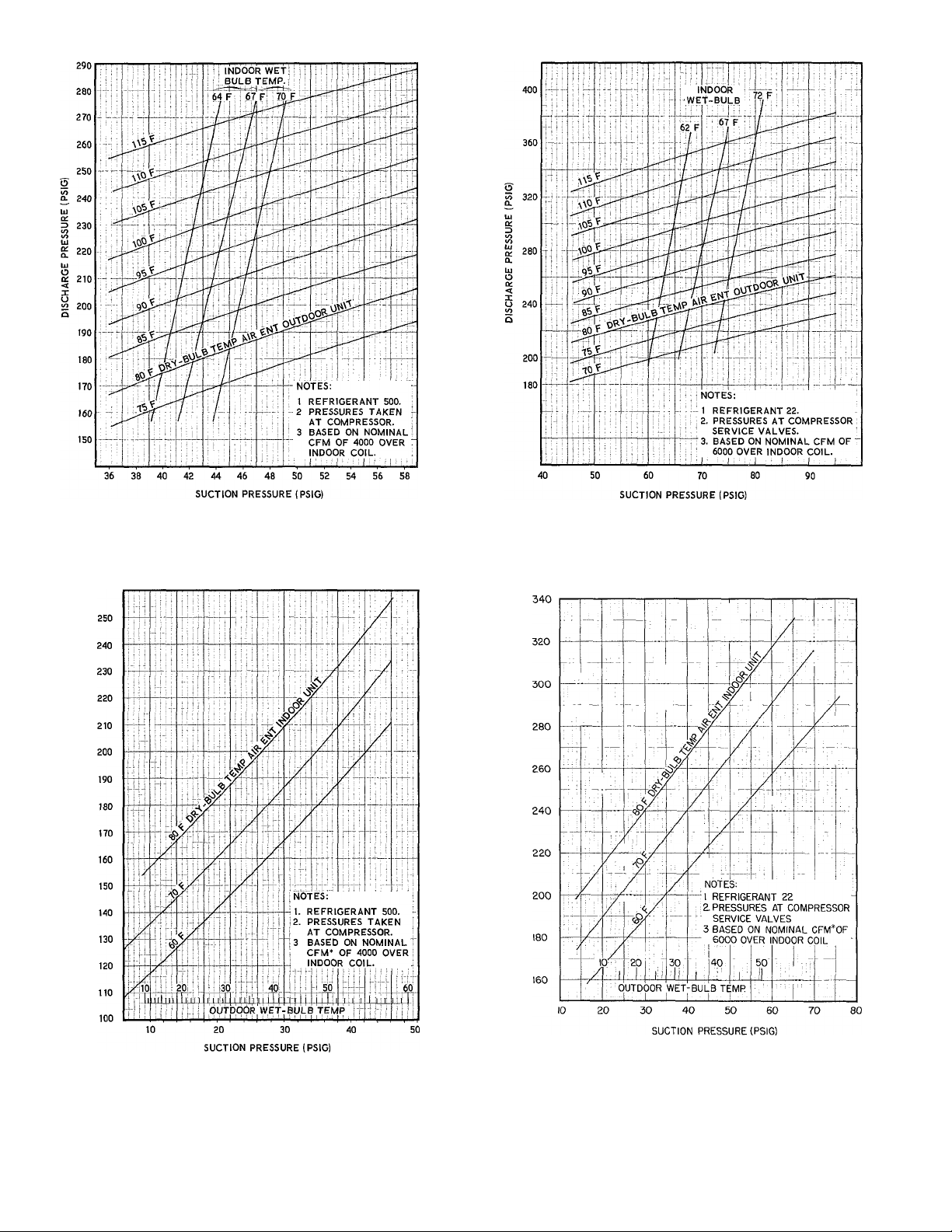
COOLING CYCLE
Oi
Ill
O
Q.
o
V)
O
38AC012 with 40RT012 Indoor Unit
38AC016 with 40RT016 Indoor Unit
HEATING CYCLE
38AC012with 40RT012 Indoor Unit
‘Minimum cfm that will allow the unitsto operate at 80 F indoor return air and 65 F
operating efficiency of system and reduce operating costs
Fig. 1 - Charging Charts
38AC016 with 40RT016 I ndoor Unit
wb outdoor air on heating cycle. Higher air quantities increase
2
Page 3

NOTE: Do not depend on sight glass when
charging unit. Use the charging chart. ■
3. Allow system to operate for about 20 minutes.
Take temperature and pressure readings and
check values with the charging chart.
After Charging System, allow unit to run for about
20 minutes. Stop unit and check compressor oil
level. Add oil only if necessary to bring oil into
view in sight glass. If oil is added, run unit for
additional 10 minutes. Stop unit and check oil
level. If level is again low, add oil only after
determining that piping system is designed for
proper oil return and that system is not leaking oil.
Check operation of all safety controls. Replace all
service panels. Be sure that control panel door is
closed tightly.
SERVICE
Defrost Control, consisting of a defrost timer and a
defrost thermostat, interrupts normal system
heating operation if enough frost forms on outdoor
coil to impair overall unit performance. Defrost
control simultaneously stops outdoor fans and
de-energizes reversing valve solenoid to return
system to cooling cycle (outdoor unit as con
denser; indoor unit as evaporator). Defrost cycle is
90 minutes for 38AC012 and 60 minutes for
38AC016.
For the heat pump to defrost, two conditions
are necessary:
1. Defrost timer contacts must be closed.
2. Refrigerant temperature from outdoor unit
must be cold enough (43± 3 F) to cause defrost
thermostat contacts to close.
Liquid Line Low-Pressure Control (LLP) is con
nected in liquid line to work with compressor
internal thermostat and discharge thermostat to
provide loss-of-charge protection during the heating
cycle. Control is mounted in control box.
With a high side leak, pressure gradually
decreases until low pressure control stops the
compressor.
With a low side leak there will always be some
pressure in the liquid line. However, compressor
motor temperature will increase because of in
sufficient suction gas cooling. This causes internal
thermostat or discharge line thermostat to actuate
and stop compressor. When compressor stops,
system pressure equalizes and contacts on pressure
control open. The compressor cannot restart until
leak is repaired and system recharged.
Low-Pressure Control (LP) is a single-pole switch
connected into the refrigerant system at com
pressor suction connection and into 24-volt control
circuit. Control provides loss-of-charge protection
and freeze-up protection during cooling cycle and
is inoperative during heating cycle. See Table 1 for
pressure settings.
Head Pressure Control (Fan-Cycling Thermostat) —
A feeler bulb in the outdoor coil inlet airstream
senses temperature of air entering coil to control
no. 2 fan on 38AC012 and no. 2 and 3 fans on
38AC016. Open and close temperatures are shown
in Table 1.
Accessory Motormaster^M head pressure con
trol for no. 1 fan (if used) allows operation at
lower ambients. See accessory instructions.
Time Guard Circuit for compressor causes a
5-minute delay before restarting compressor after
shutdown for any reason. On starting, the Time
Guard Timer causes a delay of 15 seconds after
thermostat closes before compressor will start. On
compressor shutdown, the timer recycles for 4
minutes 45 seconds. During this time the com
pressor cannot restart.
Safety Relief — A rupture disc in the accumulator
and a relief valve in the compressor provides
pressure relief under abnormal temperature and
pressure conditions.
Electric Resistance Crankcase Heater is inserted
into the compressor crankcase. It is operated from
the normally closed contacts of the holding relay
and is automatically energized when the com
pressor stops. This heater keeps crankcase warm to
prevent oil dilution by refrigerant and ensures good
lubrication and minimizes loss of oil during
start-up.
If power to unit has been off for an extended
period of time, energize crankcase heater at least 3
hours prior to starting compressor.
Compressor Section — Remove top and end panel
for access to this section. Additional access to
expansion valve, distributor and coil piping is
available by removing inboard fan, motor-support
panel assembly and coil end baffle between com
pressor section and coil section. Remove fan and
motor-support panel assembly by removing six
sheet metal screws, three cap screws and dis
connecting fan cable at control box. Then remove
coil end baffle.
Fan Adjustment — Turn unit power off. Remove
fan guard and loosen fan hub setscrew. Adjust fan
until surface of hub is 3/8 in. below top of venturi
rim as shown in Fig. 3. Then, tighten setscrew on
flat of motor shaft. Seal fan hub recess with
permagum to prevent hub from rusting to motor
shaft.
Lubrication
OUTDOOR FAN MOTORS have sealed bearings.
No provisions are made for lubrication.
COMPRESSOR has its own oil supply. Loss of oil
due to a leak in the system should be the only
reason for adding oil after system has been in
operation.
To Add or Remove Compressor Oil — Refer to
Carrier Standard Service Techniques Manual,
Chapter 1.
Page 4

38AC016 WITH 40RT016
Heating Cycle
9 Hot gas from compressor flows thru muffler to reversing
valve
o Hot gas is directed to header on indoor coils. In these coils
hot gas is condensed to a liquid This liquid flows out thru
feeder tubes to the distributors where it passes thru the side
outlet TXV B and B-| are closed because of high equalizing
pressure
o Liquid flows thru check valve C proceeding to outdoor unit.
O Liquid flows thru filter-drier, TXV (A), distributor, and
feeder tubes into outdoor coil where it is evaporated into a
vapor (Entire outdoor coil is an evaporative surface during
this cycle )
0
Cool vapor from outdoor coil subcooler is pulled thru check
valve A and meets with gas flowing from remainder of
outdoor coil (check valve B closed).
0 Cool vapor flows thru reversing valve where it is directed to
accumulator and into compressor suction valve to repeat
cycle.
38AC PIPING LEGEND
HEATING CYCLE 0
COOLING CYCLE @ ~i
COMPRESSOR
----------
SOLENOID OPERATED
REVERSING VALVE
(SOLENOID ENERGIZED ON HEATING
DE-ENERGIZED ON COOLING)
Cooling Cycle
JA;! Hot gas from compressor flows thru muffler to reversing
valve
i®) Hot gas is directed to header on outdoor coil (check valve A
closed)
Header directs hot gas to individual coil circuits where it is
condensed to liquid.
Liquid out of outdoor coil makes 180 degree turn in
distributor and flows thru tubes to and thru subcooler. TXV
(A) is closed because of high equalizing pressure.
Subcooled liquid flows thru check valve B and toward indoor
unit
i":'i Liquid continues thru filter-drier, expansion valve B and
B-) into distributors and into indoor coils Check valve C is
closed.
Cool vapor flows out of indoor coil back to reversing valve
where it is directed to accumulator and then to compressor
suction valve to repeat cycle.
38AC012 WITH 40RT012
These combinations follow the same basic diagram with two
exceptions
There is only one coil on the indoor unit and therefore only
one expansion valve. Also the 40RT012 is provided with a
subcooling coil which performs two functions
On heating cycle it is full of liquid which tends to balance the
refrigerant charge while providing subcooling.
On cooling cycle a check valve prevents liquid refrigerant
from entering the subcooler coil; this portion has vapor only.
Fig. 2 — Heat Pump Cycle (Heating and Cooling)
MOISTURE INDICATOR
SIGHT GLASS
Page 5

Table 2 — Electrical Data (3-Ph, 60-Hz)
UNIT
MODEL
38AC
012
38AC
016
FLA — Full Load Amps
FU — Fuse (max allowable amps; dual element)
ICF — Maximum Instantaneous Current Flow (during start-up:
LRA
NDSV
WSA
*Unit 38AC012 has two; Unit 38AC016 has three
VOLTS NDSV
^■ 430
208
550
230
640
430
540
640
sum of LRA for compressor plus FLA for all other motors
in the unit)
— Locked Rotor Amps
— Nominal Distribution System Voltage (Application Range)
Motors and controls will operate satisfactorily 10 percent
above and 10 percent below NDSV
— Wire Sizing Amps per NEC Tables 310-12 thru 310-15
Values are sums of 125 percent of FLA of compressor plus
F LA of all other motors in the unit
220^240165 5
460
440-480;^30 9
208'
230 1220-230181 7
460 440-480)39 0
WSAÍ ICF
208 172 6
208 ”|90’^'
197 ó
178 6
89.5
273 'S
249 8
125 7
FU
s'?
75
35
100
90
45
COMPR_
FLA LRÁ
50 C
191
45 0
172
86
22.2
64 C
266'
58 0
240
29.0
12c
FANS*
FLA,fe£)
3 2
3.2
1.6
3 2
3 2
1 6
TROUBLESHOOTING GUIDE
HEATING AND COOLING CYCLE
Compressor Will Not Run (Contactor Open)
Power off — restore power.
Transformer defective — replace transformer.
Thermostat defective — clean or replace ther
mostat.
Control relay defective — clean contacts or
replace coil.
Compressor contactor defective -- clean con
tacts or replace coil.
Holding relay defective — clean contacts or
replace coil.
Timer motor or switch defective — replace
timer.
Electrical connections loose — check and
tighten all electrical connections
Pressurestat open — check setting or replace if
defective.
Reversing valve relay defective — replace relay.
Compressor Will Not Run (Contactor Closed)
Disconnect switch open or fuse(s) blown —
restore power or replace fuses.
Compressor leads loose — tighten connections.
Compressor motor windings open ^ replace
compressor motor.
Compressor seized — check compressor
bearings.
Compressor Cycles on Protective Device
Compressor is hot — replace broken valves or
head gaskets. Check reversing valve positioning.
Overload defective — replace overload.
Line voltage outside allowable limits or 3-phase
imbalance — request assistance from power
company.
High load condition — check system charge
andjor purge noncondensables.
Compressor Cycles on High Pressure Switch
Refrigerant overcharge — purge until charge is
correct. See charging chart
Noncondensables in system — purge and
recharge.
Discharge line restricted — remove restriction.
Reversing valve damaged — replace or repair
reversing valve.
Fan cycling on overload — check fan motor
capacitor, fan motor compressor leads or fan
relay.
Filter or coils dirty — clean or replace filter.
Clean coils.
HEATING CYCLE (INSUFFICIENT HEATING)
Compressor Runs (Low Suction and Low Head
Pressure; Outdoor Fan Stopped)
Defrost relay defective — replace relay.
Outdoor fan motor leads loose — tighten motor
connections
Fan motor protection open — replace motor.
Fan motor burned out — replace motor.
Page 6

Compressor Runs (Low Suction and Low Head
Pressure; Outdoor Fan Running)
Suction valve partially closed — open valve.
Filter-drier restricted — replace filter-drier.
Expansion valve restricted or clogged — replace
expansion valve and filter-drier.
Indoor check valve defective — replace check
valve.
System undercharged — add refrigerant; see
charging chart.
Outdoor coil dirty — clean coil.
Outdoor coil heavily frosted — check defrost
circuit electrical connections. Check physical
contact between defrost thermostat sensing
bulb and liquid line. Replace defrost relay,
defrost thermostat, defrost timer or reversing
valve.
Compressor Runs (High Suction Pressure and Low
Superheat)
Compressor flooding — check position and/or
seal of outdoor check valve. Check expansion
valve operation.
Outdoor check valve leaking or backwards —
replace check valve.
Outdoor expansion valve stuck open — replace
expansion valve.
Electric Resistance Strip Heater Not Operating
Outdoor thermostat defective — check capillary
tubing for pinches Check to be sure sensing
bulb senses true outdoor temperature.
Outdoor thermostat set too low - reset
thermostat.
Heater relay or contactor defective — replace
relay or contactor
Fuses blown — replace fuses
Fuse link open — replace fuse link.
Heater element broken — replace element.
Overtemperature thermostat defective or open
— replace overtemperature thermostat or check
air flow over heater element enclosure.
Defective room thermostat second stage —
replace thermostat assembly.
COOLING CYCLE (INSUFFICIENT COOLING)
Compressor Cycles on High Pressure Switch
Outdoor air restricted or recirculating — clean
debris from coils or fans Remove shrubbery or
foliage. Install baffles to improve air flow.
Outdoor fan stopped — check fan power,
operation of fan relay or defrost relay. Replace
defective or damaged parts.
Compressor Cycles on Low Pressure Switch
(Indoor Fan Stopped)
Indoor fan motor or relay defective — replace
motor or relay. Check motor protection.
Electrical connections loose — check and
tighten all connections.
Fan belt sUps or is broken — adjust belt tension
or replace belt.
Compressor Cycles on Low Pressure Switch
(Indoor Fan Running)
Indoor air coil iced up — check expansion valve
and refrigerant charge.
Refrigerant charge low — add charge; see
charging chart.
Expansion valve closed or plugged ^ clean or
replace expansion valve.
Filter-drier restricted — replace filter-drier.
Outdoor check valve restricted or backwards —
replace check valve.
Compressor Runs (Low Suction Pressure)
Coil frosted — clean or replace air filter.
Ducts restricted — clean ductwork.
Dampers partially closed — adjust dampers
correctly.
Refrigerant charge low — add charge; see
charging chart.
Liquid line restricted — replace filter-drier if
restricted. Replace expansion valve power
element if defective. Replace outdoor check
valve if stuck.
Compressor Runs
(High Suction; Low Head Pressure)
Reversing valve hung up or leaks internally —
replace reversing valve.
Compressor valves or head gasket defective —
replace valves or gasket.
Compressor Runs
(High Suction Pressure; Low Superheat)
Compressor flooding — check position and/or
seal of indoor check valve. Check expansion
valve operation.
Indoor expansion valve stuck open — replace
expansion valve.
Manufacturer reserves the right to change any product specifications without notice.
CARRIER AIR CONDITIONING COMPANY • SYRACUSE, NEW YORK
Tab 12 Form 38AC-2SS Supersedes 38AC-1SS Printed in U S A. 4-69 Codes B and MS Catalog No 533-806
 Loading...