

Page 1
Programmable Thermostat
Am
COOL
HEAT
AUTO
BACK LIT
LIQUID
CRYSTAL
DISPLAY
MODE
BUTTON
FAN
BUTTON
HEAT/COOL INDICATOR
RED = HEAT
GREEN = COOL
UP AND DOWN
ARROW BUTTONS
Mo
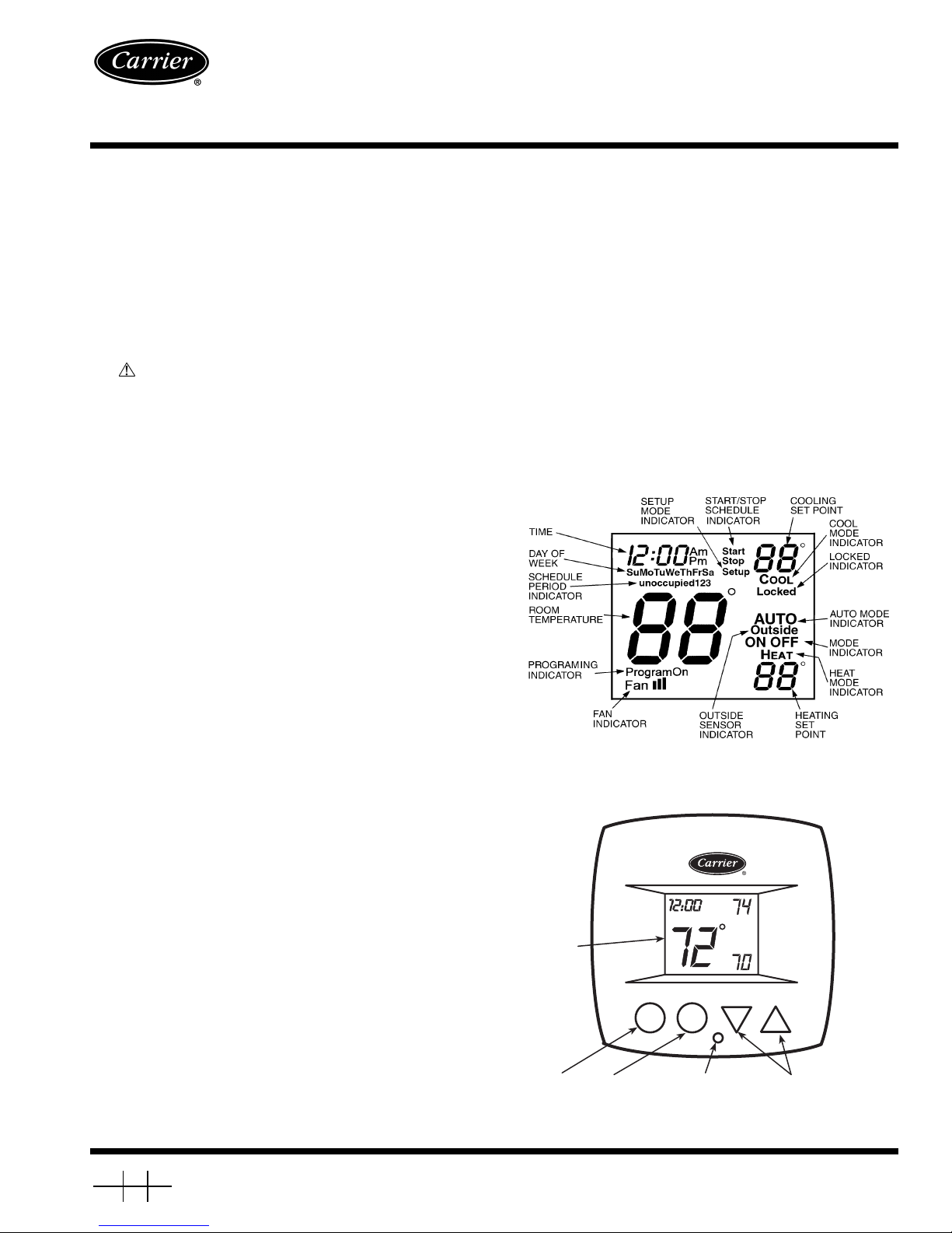
Fig. 1 — Thermostat Display
Fig. 2 — Thermostat Front Panel Buttons
Owner’s Manual
Part Number 33CSSP2-FC
33CS
Fan Coil
SAFETY CONSIDERATIONS
Read and follow manufacturer instructions carefully. Follow all local electrical codes during installation. All wiring
must conform to local and national electrical codes. Improper
wiring or installation may damage thermostat.
Recognize safety information. This is the safety al ert symbol . When the safety alert symbol is present on equipment
or in the instruction manual, be alert to the potential for personal injury.
Understand the sig nal words DANGER, WAR NING, and
CAUTION. These words are used with the safety alert symbol.
DANGER identifies the most se rious hazards which will re sul t
in severe personal injury or death. WA RNING signifies a haz ard which could result in personal injury or death. CAUTION
is used to identify unsafe practices which would result in minor
personal injury or property damage.
GENERAL
The fan coil programmable thermostats are wall-mounted
or unit-mounted, low-voltage thermostats which maintain
room temperature by controlling the operation of a fan coil
unit. Separate heating and cooling set points, auto-changeover
capability, 2 or 4-pipe configurability, and single or dual set
point options allow for greater flexibility.
All thermos tats allow up to 4 time/temper ature settings t o
be programmed per 24-hour period. Each thermostat stores
programs for 7 independent days. Batteries are not required.
During power interruption the internal NEVERLOST™ memory stores configuration settings for an unlimited time while
the clock continues to run for at least 48 hours.
The thermostat can be configured to accept several different
equipment configurations, including 2 or 4 pipe operation.
The temperature display range of the thermostat is 35 to
99 F (2 to 36 C).
NOTE: The thermostat is factory-configured fo r use in 4-pipe
applications. The advanced setup must be performed to configure the thermostat for use with 2-pipe applications.
Heat or Cool Indicator —
A Heat or Cool indicator is
located on the bottom middle cover of the thermostat. See
Fig. 2. The light will be red if the thermostat is in Heating
mode. The light will be green if the thermostat is in Cooling
mode.
Thermostat Front Panel Buttons —
The thermostat has buttons on the front cover which are used to raise or
lower the desired set point and change the current mode. See
Fig. 2.
SET POINT BUTTONS — The UP ARROW and DOWN
ARROW buttons will raise or lower the current desired temperature set point.
OPERATION
Thermostat Display —
ed in the center of the thermostat. See Fig. 1. The following
information can be displayed on the screen:
• time
• day of week
• mode (OFF, HEAT, COOL, Program On, or AUTO)
• fan setting (auto, low, medium, or high)
• room temperature
• desired temperature
• setup indicator
• lock indicator
• programm i ng indicator s
• schedule indicators
• outside sensor indicator
Book 1 4
Ta b 1 1 a 1 3 a
Manufacturer reserves the right to discontinue, or change at any time, specifications or designs without notice and without incurring obligations.
PC 111 Catalog No. 533-30004 Printed in U.S.A. Form 33CS-18SO Pg 1 6-03 Replaces: 33CS-15SO
The thermostat display is loca t-
Page 2

FAN BUTTON — The fan button determines fan operation.
The fan can be set to Auto, Off, Low, Medium, or High.
MODE BUT TON — The Mode button selects the operating
mode of the thermostat. The mode can be set to Heat, Cool,
Auto, or Off.
NOTE: Certain modes may be locked out by the type of application or the reading of the changeover sensor.
Set Clock —
The
Set Clock function allows the user to
change the time and day displayed on the thermostat. Press and
hold the Mode and Fan buttons at the same time for 2 seconds
until the display changes. The display will show the Setup annunciator. The current time will blink on and off. Press the UP
ARROW and DOWN ARROW buttons until the correct time
is shown. Hold down the buttons to quickly move through the
time display. The AM and PM annunciators will automatically
change. To scroll through by hours instead of minutes, hold
down the Fan button while pressing UP ARROW or DOWN
ARROW. To ensure the schedules are properly followed, make
sure that AM or PM is correct for the ti me chosen. When t he
correct time is shown, press the Mode button to modify the day
of the week. The current day will blink on and off. Press the UP
ARROW and DOWN ARROW buttons until the correct day is
shown. Press the and hold the Mode and Fan buttons at the
same time agai n to ex it the Set Cl ock mode.
Program Thermostat Schedules —
Before programming the thermostat, plan the thermostat daily schedule.
The schedule is divided into 7 days (Monday through Sunday).
Each day has from 2 to 4 time periods (Occupied 1, Occupied
2, Occupied 3, Unoccupied) depending on the configuration of
the thermostat. Each occupied time period has a start time, stop
time, heating set point, and cooling set point. The unoccupied
time period has a heating set point and a cooling set point. The
unoccupied time period is active whenever an occupied tim e
period is not active. Fill in Table 1 as an aid to programming
the daily schedules.
PROGRAMMING MOD E — To program the daily schedules, perform the following procedure:
1. Enter Programming mode by pressing and holding the
Mode and UP ARROW buttons. The Occupied 1 annunciator will appear on the thermostat display. Use the UP
ARROW and DOWN ARROW buttons to set the
maximum number of Occupied periods for each day. The
thermostat can be set to 1, 2, or 3. After the number of
Occupied periods has been selected, press the Mode
button. See Fig. 3.
2. The cooling set point for Occupied 1 will be displayed.
Use the UP ARROW and DOWN ARROW buttons to
raise or lower the cooling set point until the desired temperature is shown. The range of acceptable values is 35 to
99 F (2 to 36 C). Press the Mode button to continue. See
Fig. 3.
3. The heating set point for Occupied 1 will be displayed.
Use the UP ARROW and DOWN ARROW buttons to
raise or lower the heating set point until the desired temperature is shown. The range of acceptable values is 35 to
99 F (2 to 36 C). Press the Mode button to continue. See
Fig. 3.
4. The cooling set point for Unoccupied will be displayed.
Use the UP ARROW and DOWN ARROW buttons to
raise or lower the cooling set point until the desired temperature is shown. The range of acceptable values is 35 to
99 F (2 to 36 C) or ‘‘OF’’ (no unoccupied cooling). To
configure the Unoccupied Cooling set point to OF, press
the DOWN ARROW button until 35 F (2 C) is displayed.
Press the DOWN ARROW button again to display OF.
Press the Mode button to continue.
5. The heating set point for Unoccupied will be displayed.
Use the UP ARROW and DOWN AR ROW buttons to
raise or lower the heating set point until the desired temperature is shown. The range of acceptable values is 35 to
99 F (2 to 36 C). Press the Mode button to continue.
6. The day of the week will be shown. Use the UP ARROW
and DOWN ARROW buttons to change the day of the
week until the desired starting day is shown. Possible
choices are Mo (Monday) through Su (Sunday). Press the
Mode button when the desired day is shown.
7. The Start Time for Occupied 1 will be displayed. Use the
UP ARROW and DOWN ARROW buttons to raise or
lower the time until the desired Start Time is shown.
Press the Mode button to continue. See Fig. 4.
8. The Stop Time for Occupied 1 will be displayed. Use the
UP ARROW and DOWN ARROW buttons to raise or
lower the time until the desired Stop Time is s hown. Press
the Mode button to continue.
9. The On/Off icon will be displayed. Use the UP ARROW
to turn the Occupied 1 period ON for this day. Use the
DOWN ARROW to turn the Occupied 1 period OFF for
this day.
10. Repeat Steps 2 through 9 to program the remaining
schedule for Occupied periods 2 and 3.
11. The Copy command can be used to copy the previous
day’s schedule if the schedules are the same. The copy
command becomes available after all t he occupied periods are programmed in a day. Use the UP ARROW to
change the copy command to YES. Use the DOWN
ARROW to change the copy command to NO. Press the
Mode button when the choice has been made. See Fig. 5.
If NO was selected, the schedule will automatically
change to the next day and the user must e nter the occupied and unoccupied schedules for that day.
NOTE: Occupied 1 schedule heating and cooling set
points are the same for each day. Occupied 2 and 3 set
points may be set to different values for each day of the
week.
If YES was selected, the schedule will be copied to the
next day. The schedule copy may be repeated until Sunday is reached. The Sunday schedule cannot be copied to
Monday.
12. After all the times and set points for each day have been
entered, press and hold the Mode and UP ARROW
buttons to exit Programming mode.
NOTE: The thermostat will continue to follow the schedule
until a new one is entered.
If only one occupied schedule is selected, the Occupied 2
and 3 schedules are skipped. If the start time is set later in the
day than the stop time, the program will run from midnight of
that day to th e stop time an d then from the start ti me to midnight. If the same start and stop times are programmed for an
occupancy schedule, the thermostat will be in Occupied mode
for 24 hours. If one occupied period starts or stops within another occupied period, the lower numbered schedule has priority. F or example, if schedule Occupied 3 is running for 24 hours
and Occupied 2 schedule comes on from 1 to 3 PM, the set
points from Occupied 2 are in effect from 1 to 3 PM.
OVERRIDING THE SCHEDULE — The schedule can be
overridden by pressing the UP or DOWN ARROW buttons to
change the desired temperature. The thermostat will use the
new set point until the next scheduled time period starts.
2
Page 3
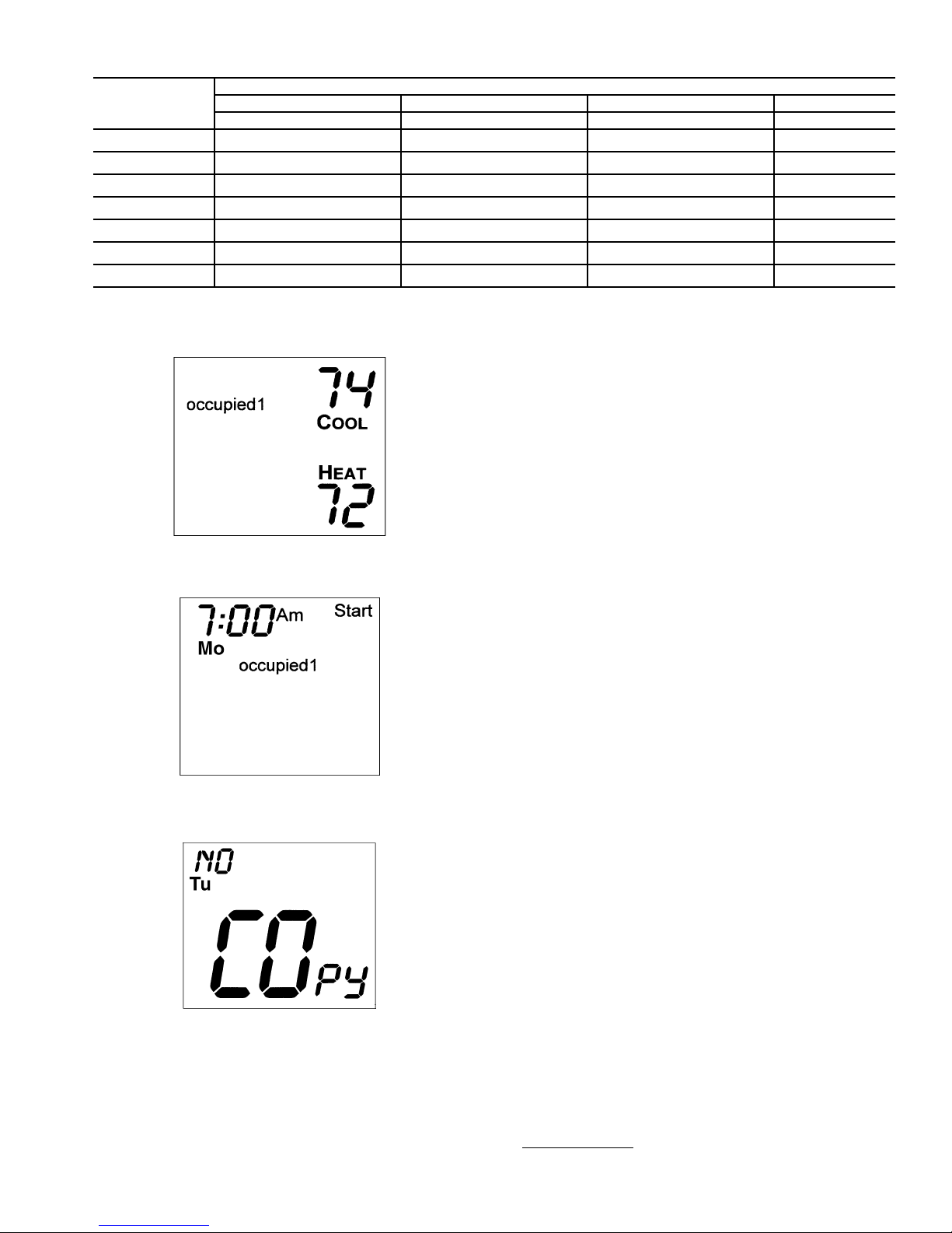
Table 1 — Daily Schedule Planner
DAY
OF THE
WEEK
Monday
Tuesday
Wednesday
Thursday
Friday
Saturday
Sunday
NOTE: The cooling temperature set point must be higher than the heating temperature set point. (The temperature difference may be changed in
the advanced set up configuration by the installer.)
Occupied 1 Occupied 2 Occupied 3 Unoccupied
Start / Stop / Heat / Cool Start / Stop / Heat / Cool Start / Stop / Heat / Cool Heat / Cool
/// /// /// /
/// /// /// /
/// /// /// /
/// /// /// /
/// /// /// /
/// /// /// /
/// /// /// /
SCHEDULE
NOTE: If the Single Set Point mode is configured by the
installer, there will be only one set point for both heating and
cooling.
Four-Pipe Operation —
The Mode button selects the
operating mod e of th e the rmos tat. If OFF is se lected, the thermostat will not enter Heating or Cooling mode. If HEAT is selected, the thermostat will only enter Heating mode (if the
room temperature is below the heating set poi nt). If COOL is
selected, the thermostat will only enter Cooling mode (if the
room temperature is above the cooling set point). If AUTO is
selected, the thermostat w ill enter Heating or Cooling mode
based on the room temperature and the heating and cooling set
Fig. 3 — Setting Occupied 1 Set Points
points. If Program On is selected, the thermostat will follow the
occupied schedule.
Two-Pipe Operation
NOTE: The thermostat default is 4-pipe operation. The thermostat must be configured for 2-pipe operation.
HEAT O NLY — When the thermostat is configured for Heat
Only operation, only Heat, Program On, and Off modes can be
selected.
COOL ON LY — When the thermostat is configured for Cool
Only operation, only Cool, Program On, and Off modes can be
selected.
HEAT/COOL WITH CHANGEOVER SENSOR — When
the thermostat is configured for operation with a changeover
Fig. 4 — Start Time Display
Fig. 5 — Copy Command Display
Select Desired Temperature —
The UP and DOWN
ARROW buttons are used to adjust the heating and cooling set
points. Pressing the UP and DOWN ARROW buttons in Auto
mode will adjust both the heating and cooling set points. Pressing the UP and DOWN ARROW buttons in either Heat or
Cool mode will adjust only the heating or cooling set point.
sensor, all the modes are available for operation. If the water
temperature is changed during the year, the thermostat will automatically lock out the incorrect mode. Heat or Cool modes
may not be available, depending on water temperature.
TOTAL OR AUXILIARY ELECTRIC HEAT — The Mode
button selects the operating mode of the thermostat. If OFF is
selected, the thermostat will not enter Heating or Cooling
mode.
If HEAT is selected, t he thermos tat wi ll only ente r Heati ng
mode (if room temperature is below the heating set point). For
total electric heat, a call for heat will activate the electric heater.
For auxiliary electric heat, a call for heat will either activate the
electric heater (if chilled wat er is in the coil), or open the coil
valve (if hot wate r is i n the coil) .
If COOL is selected, the thermostat will only enter Cooling
mode (if room temperature is above the cooling set point and
chilled wat er is in th e coil ).
If AUTO is selected, Heating or Cooling mode based on the
room temperature and the heating and cooling set points.
NOTE: Certain modes may be locked out by the type of application or the reading of the changeover sensor.
Auto-Changeover
— When the thermostat mode is set to
AUTO, the thermostat will provide automatic changeover from
3
Page 4

Heating to Cooling mode and Cooling to Heating mode when
required. The t he rmo sta t w il l au tom a tical ly s w itc h to m ai ntai n
the desired temperature setting. The thermostat does not need
to be manually changed from heating to cooling or cooling to
heating operation.
NOTE: It is recommended that auto-changeover mode not be
used if the outdoor temperature is consistently lower than 50 F
(10 C) or greater than 80 F (27 C). In thes e cas es, select H eating or Cooling mode only.
Fan Operation —
eration. When only the Fan icon is shown, the fan is in “Auto”
mode and will run continuously (unless thermostat mode is set
to Off or thermostat is in unoccupied mode and heating or cooling are not active). The thermostat will increase or decrease the
fan speed based on temperature demand.
Fan operation can also be set to always run at Low, Medium, or High speeds. To set fan operation at Low speed, press
the Fan button until one bar is shown next to the Fan icon. The
fan will run continuously at Low speed (unless thermostat
mode is set to Off or thermostat is in unoccupied mode and
heating or cooling are not active).
To set fan operation at Medium speed, press the Fan button
until two bars are shown next to the Fan icon. The fan will run
continuously at Medium speed (unless thermostat mode is set
to Off or thermostat is in unoccupied mode and heating or cooling are not active).
T o set fan operation at High speed, press the Fan button until three bars are shown next to the Fan icon. The fan will run
continuously at High speed (unless thermostat mode is set to
Off or thermostat is in unoccupied mode and heating or cooling
are not active).
Keypad Lock —
mostat, the front panel buttons can be disabled. To disable or
lock the keypad, press and hold the Mode button. While holding down the Mode button, press the UP and DOWN ARROW
buttons simultaneously. The ‘‘Locked’’ icon will appear on the
display .
The thermostat is unlocked by performing the sam e procedure. Press and hold the Mode button. While holding down the
Mode button, press the UP and DOWN ARROW buttons simultaneously. The ‘‘Locked’’ icon will be removed from the
display .
Clock Backup —
mostat internal clock will continue to keep proper time for a
minimum of 48 hours without external power or batteries.
The Fan button is used to select fan op-
T o prevent unauthorized use of the ther-
In the event of a power loss, t he ther-
Minimum Heat/Cool Temperature Difference —
lowed to be set any closer to each other than the value set by
the installer. The minimum temperature difference is enforced
during Auto mode and Program On operation.
The heating and cooling set points will not be al-
Single Set Point Operation —
is configured for single set point operation, the display on the
thermostat will change. Instead of displaying current room
temperature, the large number shown will be the user set point.
This set point is used for both heating and cooling. Press and
hold the Mode button for 2 seconds to display the room temperature. Press any button to return to the normal display.
Dual Set Point Operation —
configured for dual set point operation, there are separa te heat
and cool set points. The adjustable set point range is 35 to 99 F
(2 to 36 C). When the thermostat is in Heat or Cool mode, the
set points can be adjusted to any temperature within the operating range.
When the thermostat is in Auto mode, the thermos tat will
not allow the Cool set point to be lower than the Heat set point.
The thermostat will also use the programmed Deadband value
(configured by installer) to determine the minimum difference
between the Heat and Cool set points. If the Deadband is set for
6 degrees, the Cool set point cannot be set within 6 F of the
Heat set point.
When entering Auto mode from Heat or Cool modes, the
Heat and Cool set points will remain spread apart by the sam e
amount when the set points are adjusted. For example, if the
Cool set point is 80 F (adjusted in Cool mode) and the Heat set
point is 70 F (adjusted in Heat mode), then when entering Auto
mode, both set points would be adjusted by the same amount
when the UP and DOWN ARROW buttons are pressed. Therefore, if the DOWN ARROW was pressed 5 times, the Cool set
point would be 75 F and the Heat set point would be 65 F.
To adjust the set points individually, enter the Heat or Cool
modes first.
Outside Sensor —
2 seconds to display outside temperature (if optional outdoor
sensor is wired to thermostat). Press any button to return to normal operation.
Locking Cover —
screws is provided with the thermostat. The locking cover can
be used to keep the thermostat set points and configurations
from being changed. A special tool is required to remove the
cover.
Press and hold the Fan button for
A locking cover with tamper-proof
Dry Contact Switch/External Control —
contact switch is provided to allow an external device to force
the thermostat into Occupied 1. When the thermostat is forced
into Occupied 1 via the dry contact closure, the Occupied 1
icon will blink each second.
In some cases, the dry contact switch may be configured to
disable the fan, heating, and cooling from a condensate overflow switch. In those applications, the fan coil unit will be deactivated when the switch is energized.
When the ther mo st at
When the thermostat is
A dry
4
Page 5
5
Page 6

6
Page 7

Page 8

Copyright 2003 Carrier Corporation
Manufacturer reserves the right to discontinue, or change at any time, specifications or designs without notice and without incurring obligations.
Book 1 4
Ta b 1 1 a 1 3 a
PC 111 Catalog No. 533-30004 Printed in U.S.A. Form 33CS-18SO Pg 8 6-03 Replaces: 33CS-15SO
 Loading...